

Sony KDL-22BX32, KDL-32BX326, KDL-32BX42, KDL-32BX32, KDL-40BX42 Service Manual
...
SERVICE MANUAL
LCD Digital Color TV
AZ2-TK Chassis
9-883-856-01
Version Date Subject
1.0 1/13/2011 No revisions or updates are applicable at this time.
ORIGINAL MANUAL ISSUE DATE: 1/2011
HISTORY INFORMATION FOR THE FOLLOWING MANUAL:
SERVICE MANUAL
LCD Digital Color TV
AZ2-TK Chassis
9-883-856-01
Self Diagnosis
Supported model

MODEL LIST
MODEL COMMANDER DESTINATION MODEL COMMANDER DESTINATION
KDL-22BX325 RM-YD066 CHILE
KDL-22BX325 RM-YD066 VENEZUELA
KDL-32BX325 RM-YD066 CHILE
KDL-32BX325 RM-YD066 VENEZUELA
KDL-32BX326 RM-YD066 CHILE
KDL-32BX326 RM-YD066 VENEZUELA
KDL-32BX425 RM-YD066 CHILE
KDL-40BX425 RM-YD066 CHILE
KDL-40BX425 RM-YD066 VENEZUELA

KDL-22BX325/32BX325/32BX326/32BX425/40BX425 i
TABLE OF CONTENTS
Warnings and Cautions ..................................................................................................................................................................1
Safety-Related Warning ..................................................................................................................................................................2
Safety Check-Out ............................................................................................................................................................................3
Self Diagnosis Functions ...............................................................................................................................................................5
Specications..................................................................................................................................................................................9
SEC 1. Disassembly/Part Number Information ..........................................................................................................................11
1-1. Table-Top Stand Assembly Removal ............................................................................................................................. 11
1-2. Rear Cover and Speakers Removal ..............................................................................................................................12
1-2-1. KDL-22BX325 Only ................................................................................................................................................................. 12
1-2-2. KDL-32BX325/32BX326/32BX425/40BX425 Only.................................................................................................................. 13
1-3. A Board, LIPS22/GT32/GT40 (Power) Board and LCD Panel Removal .......................................................................14
1-3-1. KDL-22BX325 Only ................................................................................................................................................................. 14
1-3-2. KDL-32BX325/32BX326/32BX425 Only ................................................................................................................................. 15
1-3-3. KDL-40BX425 Only ................................................................................................................................................................. 16
1-4. Cleaning the LCD Panel Assembly................................................................................................................................17
1-5. Screw Legend................................................................................................................................................................17
1-6. Connectors ...................................................................................................................................................................17
1-6-1. KDL-22BX325 Only ................................................................................................................................................................. 17
1-6-2. KDL-32BX325/32BX326/32BX425/40BX425 Only.................................................................................................................. 17
1-7. Accessories and Packing ..............................................................................................................................................18
1-8. Miscellaneous ................................................................................................................................................................18
1-9. Remote Commander .....................................................................................................................................................18

KDL-22BX325/32BX325/32BX326/32BX425/40BX425 ii
1-10. Wire Dressing Diagrams ................................................................................................................................................19
1-10-1. KDL-22BX325 Only ................................................................................................................................................................. 19
1-10-2. KDL-32BX325/32BX326 Only ................................................................................................................................................. 20
1-10-3. KDL-32BX425 Only ................................................................................................................................................................. 21
1-10-4. KDL-40BX425 Only ................................................................................................................................................................. 22
SEC 2. Service Adjustments ........................................................................................................................................................23
SEC 3. Diagrams ...........................................................................................................................................................................24
3-1. Circuit Boards Location .................................................................................................................................................24
3-1-1. KDL-22BX325 Only ................................................................................................................................................................. 24
3-1-2. KDL-32BX325/32BX326/32BX425/40BX425 Only.................................................................................................................. 24
3-2. Block Diagram ...............................................................................................................................................................25
KDL-22BX325/32BX325/32BX326/32BX425/40BX425 1
CAUTION
These servicing instructions are for use by qualifi ed service personnel only. To reduce the risk of electric shock, do not perform any servicing
other than that contained in the operating instructions unless you are qualifi ed to do so.
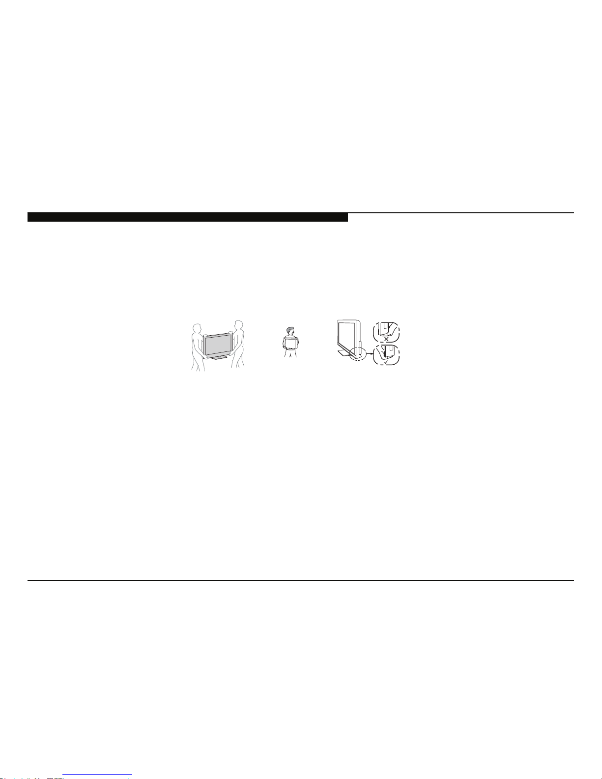
CARRYING THE TV
WARNINGS AND CAUTIONS
• Disconnect all cables when carrying the TV.
• Carry the TV with the adequate number of people; larger size TVs require two or more people.
• Correct hand placement while carrying the TV is very important for safety and to avoid
damage.
KDL-22BX325 Only
KDL-32BX325/32BX326/32BX425/40BX425 Only
WARNING!!
An isolation transformer should be used during any service to avoid possible shock hazard, because of live chassis. The chassis of this
receiver is directly connected to the AC power line.
! SAFETY-RELATED COMPONENT WARNING!!
Components identifi ed by shading and ! mark on the exploded views are critical for safe operation.
Replace all components with Sony parts whose part numbers appear as shown in this manual or in supplements published by Sony. It is
essential that all critical parts be replaced only with the part number specifi ed in this manual to prevent electric shock, fi re, or other hazard.
Circuit adjustments that are critical for safe operation are identifi ed in this manual.
Follow these procedures whenever critical components are replaced or improper operation is suspected.
NOTE: Do not modify the original design without obtaining written permission from the manufacturer or you will void the original parts and
labor guarantee.
KDL-22BX325/32BX325/32BX326/32BX425/40BX425 2
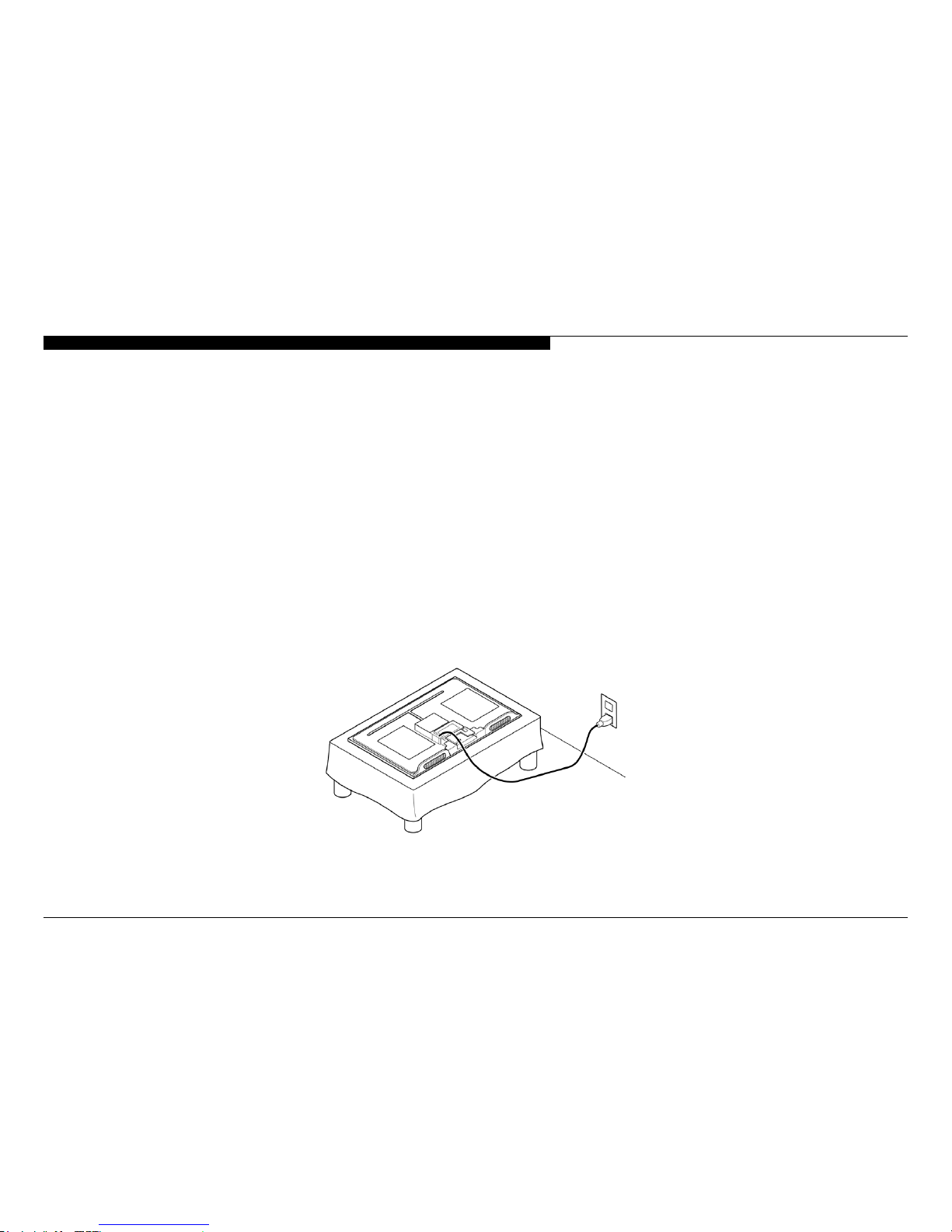
USE CAUTION WHEN HANDLING THE LCD PANEL
When repairing the LCD panel, be sure you are grounded by using a wrist band.
When installing the LCD panel on a wall, the LCD panel must be secured using the 4 mounting holes on the rear cover.
1) Do not press on the panel or frame edge to avoid the risk of electric shock.
2) Do not scratch or press on the panel with any sharp objects.
3) Do not leave the module in high temperatures or in areas of high humidity for an extended period of time.
4) Do not expose the LCD panel to direct sunlight.
5) Avoid contact with water. It may cause a short circuit within the module.
6) Disconnect the AC power when replacing the backlight (CCFL) or inverter circuit.
SAFETY-RELATED WARNING
(High voltage occurs at the inverter circuit at 650Vrms.)
7) Always clean the LCD panel with a soft cloth material.
8) Use care when handling the wires or connectors of the inverter circuit. Damaging the wires may cause a short.
9) Protect the panel from ESD to avoid damaging the electronic circuit (C-MOS).
10) During the repair, DO NOT leave the Power On for more than 1 hour while the TV is face down on a cloth.
KDL-22BX325/32BX325/32BX326/32BX425/40BX425 3
After correcting the original service problem, perform the following safety checks before releasing the set to the customer:
SAFETY CHECK-OUT
1. Check the area of your repair for unsoldered or poorly soldered connections.
Check the entire board surface for solder splashes and bridges.
2. Check the interboard wiring to ensure that no wires are “pinched” or touching
high-wattage resistors.
3. Check that all control knobs, shields, covers, ground straps, and mounting
hardware have been replaced. Be absolutely certain that you have replaced
all the insulators.
4. Look for unauthorized replacement parts, particularly transistors, that were
installed during a previous repair. Point them out to the customer and
recommend their replacement.
5. Look for parts which, though functioning, show obvious signs of deterioration.
Point them out to the customer and recommend their replacement.
6. Check the line cords for cracks and abrasion. Recommend the replacement
of any such line cord to the customer.
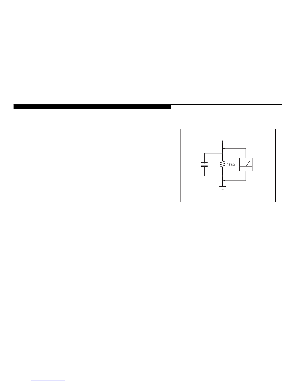
7. Check the antenna terminals, metal trim, “metallized” knobs, screws, and
all other exposed metal parts for AC leakage. Check leakage as described
below.
To Exposed Metal
Parts on Set
0.15 µF
Earth Ground
AC
Voltmete
r
(0.75V)
Figure A. Using an AC voltmeter to check AC leakage.
KDL-22BX325/32BX325/32BX326/32BX425/40BX425 4
SAFETY CHECK-OUT
LEAKAGE TEST
The AC leakage from any exposed metal part to earth ground and from all
exposed metal parts to any exposed metal part having a return to chassis, must
not exceed 0.5 mA(500 microamperes). Leakage current can be measured by
any one of three methods.
1. A commercial leakage tester, such as the Simpson 229 or RCA WT-540A.
Follow the manufacturers’ instructions to use these instructions.
2. A battery-operated AC milliampmeter. The Data Precision 245 digital
multimeter is suitable for this job.
3. Measuring the voltage drop across a resistor by means of a VOM or batteryoperated AC voltmeter. The “limit” indication is 0.75 V, so analog meters
must have an accurate low voltage scale.
The Simpson’s 250 and Sanwa SH-63TRD are examples of passive VOMs
that are suitable. Nearly all battery-operated digital multimeters that have a
2 VAC range are suitable (see Figure A).
HOW TO FIND A GOOD EARTH GROUND
A cold-water pipe is a guaranteed earth ground; the cover-plate retaining screw
on most AC outlet boxes is also at earth ground.
If the retaining screw is to be used as your earth ground, verify that it is at
ground by measuring the resistance between it and a cold-water pipe with an
ohmmeter. The reading should be zero ohms.
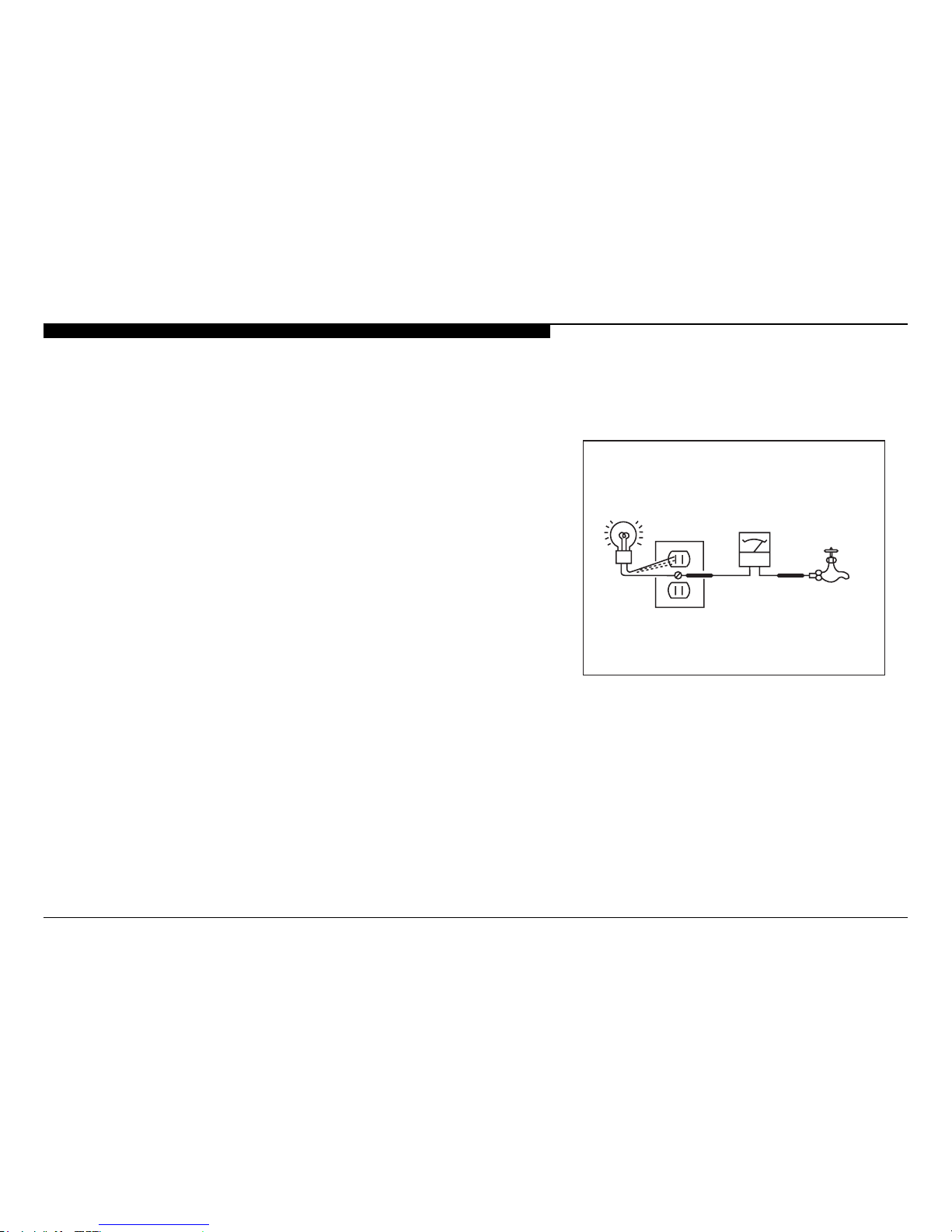
If a cold-water pipe is not accessible, connect a 60-to 100-watt trouble-light (not
a neon lamp) between the hot side of the receptacle and the retaining screw.
Try both slots, if necessary, to locate the hot side on the line; the lamp should
light at normal brilliance if the screw is at ground potential (see Figure B).
Trouble Light
AC Outlet Box
Ohmmeter
Cold-water Pipe
Figure B. Checking for earth ground.

KDL-22BX325/32BX325/32BX326/32BX425/40BX425 5
SELF DIAGNOSIS FUNCTIONS
SELF DIAGNOSIS FUNCTION
The units in this manual contain a self-diagnostic function. If an error occurs, the STANDBY LED will automatically begin to ash. The number
of times the LED ashes translates to a probable source of the problem. A denition of the STANDBY LED ash indicators is listed in the
instruction manual for the user’s knowledge and reference. If an error symptom cannot be reproduced, the remote commander can be used to
review the failure occurrence data stored in memory to reveal past problems and how often these problems occur.
DIAGNOSTIC TEST INDICATORS
When an error occurs, the STANDBY LED will ash a set number of times to indicate the possible cause of the problem. If there is more than
one error, the LED will identify the rst of the problem areas.
Result for all of the following diagnostic items are displayed on screen.
If the screen displays a “0”, no error has occurred .
Self Diagnosis
Supported model
Number of times
Standb
y
LED blinks
Diagnostic Item Possible Causes Possible Location
NA RGB_SEN RGB Sensor ACK Error NA
2 MAIN_POWER
Main Power
Over Voltage Protection
LIPS22 (Power) Board (KDL-22BX325 Only)
GT32 (Power) Board (KDL-32BX325/32BX326/32BX425 Only)
GT40 (Power) Board (KDL-40BX425 Only)
AUD_PROT Audio Error Detection
DC_ALERT DTT Error
4 BALANCER Panel Balancer Error NA
TCON ERR TCON Error
HFR ERR HFR Error
P_ID_ERR Panel ID NVM Error
PANEL_POWE Panel Error
6 BACKLITE Backlight Error
LCD Panel
LIPS22 (Power) Board (KDL-22BX325 Only)
GT32 (Power) Board (KDL-32BX325/32BX326/32BX425 Only)
GT40 (Power) Board (KDL-40BX425 Only)
7 TEMP_ERR Temperature Error A Board
3
5
A Board
TCON Control MT Board
LVDS Connection
 Loading...