

Sony KDL-32BX405, KDL-40BX405 Schematic
HISTORY INFORMATION FOR THE FOLLOWING MANUAL:
MANUAL DE SERVIÇO
AZ1-L Chassis
ORIGINAL MANUAL ISSUE DATE: 2/2010
Version Date Subject
1.1 5/2010 Alteração dos códigos das Placas Fonte
LCD Digital Color TV
9-888-298-01

Self Diagnosis
Supported model
MANUAL DE SERVIÇO
Versão 1.1
AZ1-L Chassis
LCD Digital Color TV
9-888-298-01

LISTA DE MODELOS
MODEL COLOR COMMANDER DESTINATION MODEL COLOR COMMANDER DESTINATION
KDL-32BX305 BLACK RM-YD047 BRAZIL
KDL-40BX405 BLACK RM-YD047 BRAZIL

TABLE OF CONTENTS
Speci¿ cations..................................................................................................................................................................................1
Warnings and Cautions ..................................................................................................................................................................3
Safety-Related Warning ..................................................................................................................................................................4
Safety Check-Out ............................................................................................................................................................................5
Self Diagnosis Functions ...............................................................................................................................................................7
SEC 1. Disassembly/Part Number Information ..........................................................................................................................11
1-1. Table-Top Stand Assembly Removal ............................................................................................................................11
1-2. Rear Cover, H2LS Board, and Vesa Bracket Removal ............................................................................................... 12
1-3. HLR Board and Loudspeakers Removal ..................................................................................................................... 13
1-4. G2LE/G2HE (Power) Board, BAL Board, and LCD Panel ........................................................................................... 14
1-5. Cleaning the LCD Panel .............................................................................................................................................. 15
1-6. Screw Legend .............................................................................................................................................................. 15
1-7. Connectors .................................................................................................................................................................. 16
1-7-1. KDL-32BX305 Only ............................................................................................................................................................. 16
1-7-2. KDL-40BX405 Only ............................................................................................................................................................. 16
1-8. Accessories & Packing ................................................................................................................................................ 17
1-9. Miscellaneous .............................................................................................................................................................. 17
1-10. Remote Commander ................................................................................................................................................... 17
SEC 2. Service Adjustments ........................................................................................................................................................18
2-1. Accessing Service Adjustment Mode .......................................................................................................................... 18
2-1-1. Viewing the Service Menus ................................................................................................................................................. 19
2-1-2. Using the Remote Commander to View or Change Service Data ....................................................................................... 20
KDL-32BX305/40BX405 i

TABLE OF CONTENTS
2-2. Adjustments After Replacing the BAL Board or LCD Panel ......................................................................................... 20
2-2-1. Updating the Software ......................................................................................................................................................... 20
2-2-2. Selecting the Model ............................................................................................................................................................. 21
2-2-3. Setting the Destination ......................................................................................................................................................... 22
2-2-4. Selecting the TV Color ......................................................................................................................................................... 22
2-2-5. Verifying the Model and Panel Information .......................................................................................................................... 23
2-2-6. Reconnecting All Cables ...................................................................................................................................................... 24
2-3. White Balance Adjustments ......................................................................................................................................... 24
2-4. Resetting the TV to Factory Condition ......................................................................................................................... 25
2-4-1. Resetting the TV to Factory Condition Using Service Mode ................................................................................................ 25
SEC 3. Diagrams ...........................................................................................................................................................................26
3-1. Circuit Boards Location ............................................................................................................................................... 26
3-2. Block Diagram ............................................................................................................................................................. 27
KDL-32BX305/40BX405 ii

ESPECIFICAÇÕES
Sistema
Sistema de televisão Analógico: NTSC/PAL-M/PAL-N
Cobertura de canais VHF: 2-13
Sistema do painel Painel LCD (tela de cristal líquido)
Potência de saída dos alto
falantes
Digital: SBTVD-T
UHF: 14-69
CATV: 1-125
10 W + 10 W
Tomadas de entrada/saída
CABLE/ANTENNA Terminal de antena externa de 75 ohms para entradas RF
VIDEO IN 1/2/3 VIDEO / AUDIO
COMPONENT IN 1/2 YP
HDMI IN 1/2/3/4 HDMI: Vídeo: 480i, 480p, 576i, 576p, 720p, 1080i, 1080p, 1080/24p
HEADPHONE Minitomada estéreo
AUDIO OUT 500 mVrms (típico)
DIGITAL AUDIO OUT
(OPTICAL)
PC/HDMI 4 AUDIO IN Minitomada estéreo
LAN
USB/DLNA Consulte o i-Manual para obter informações sobre o formato suportado.
*1 Para conexões LAN, utilize um cabo Category 7 10BASE-T/100BASE-TX (não fornecido).
BPR (Vídeo componente) / Formato de sinal: 480i, 480p, 576i, 576p, 720p, 1080i, 1080p / AUDIO
HDMI: Áudio: Linear de dois canais PCM 32, 44.1 e 48 kHz, 16, 20 e 24 bits, Dolby Digital
AUDIO (HDMI IN 4)
Sinal óptico PCM/Dolby Digital
BGR ocigólana ,sonip 51 ed bus-DNI CP
Conector 10BASE-T/100BASE-TX (A velocidade da conexão pode ser diferente dependendo do ambiente da
rede. A taxa e a qualidade de comunicação de 10BASE-T/100BASE-TX não estão garantidas nesta TV.)*
Informações sobre marcas
registradas
Macintosh é uma marca comercial
licenciada da Apple Inc., registrada nos
E.U.A. e em outros países.
Blu-ray Disc é uma marca comercial.
“
BRAVIA” e , S-Force e são
marcas comerciais ou marcas registradas da
Sony Corporation.
“
PS3” é uma marca comercial da Sony
Corporation e/ou Sony Computer
Entertainment Inc.
Este TV incorpora a tecnologia HighDefinition Multimedia Interface (HDMI™).
HDMI, o logotipo HDMI e High-Definition
Multimedia Interface são marcas comerciais
ou marcas registradas da HDMI Licensing,
LLC.
Astro TV é um software desenvolvido pela
TQTVD Software Ltda que implementa a
norma de interatividade do Sistema
Brasileiro de TV Digital “Ginga” ABNT
NBR-15606
1
KDL-32BX305/40BX405 1
SPECIFICATIONS
Nome do modelo KDL- 32BX305
40BX405
Alimentação e outros
Requisitos de alimentação 110-220 V AC, 60 Hz
Consumo de energia
em uso
2
em DAM*
(Você pode escutar um estalo durante o download, mas isto é normal.)
Tamanho da tela (cm)
(polegadas medidas diagonalmente)
Resolução do monitor
Alto falante (mm)
Full range com caixa acústica (2)
Dimensões com pedestal (mm) 996 × 635 × 250 804 × 532 × 220
sem pedestal (mm) 996 × 598 × 99
padrão de furo para
montagem na parede (mm)
tamanho do parafuso para
montagem na parede (mm)
Peso com pedestal (kg) 15,6 10,7
sem pedestal (kg) 13,6 9,2
Acessórios fornecidos
Acessórios opcionais Cabos de conexão / Kit de cinto de segurança / Suporte de montagem de parede
*2 Download Acquisition Mode (DAM) (modo de aquisição de download) é utilizado para atualizações de software.
• A disponibilidade dos acessórios opcionais depende do estoque.
• Projeto e especificações técnicas sujeitos a alterações sem prévio aviso.
Consulte “Verificando os acessórios” (página 5).
Aprox. 102
40 polegadas
1.920 pontos (horizontal)
× 1.080 linhas (vertical)
M6 (comprimento: veja a página 14 para detalhes.)
15 W
1.366 pontos (horizontal) ×
45 × 130
W 311W 551
AC V 022 moc W 2,0 euq sonem e AC V 721 moc W 21,0 euq soneMybdnats me
Aprox. 80
31,5 polegadas
(classe 32)
768 linhas (vertical)
804 × 497 × 96
002 × 002003 × 003
KDL-32BX305/40BX405 2
WARNINGS AND CAUTIONS
CAUTION
These servicing instructions are for use by quali ed service personnel only. To reduce the risk of electric shock, do not perform any servicing
other than that contained in the operating instructions unless you are quali ed to do so.
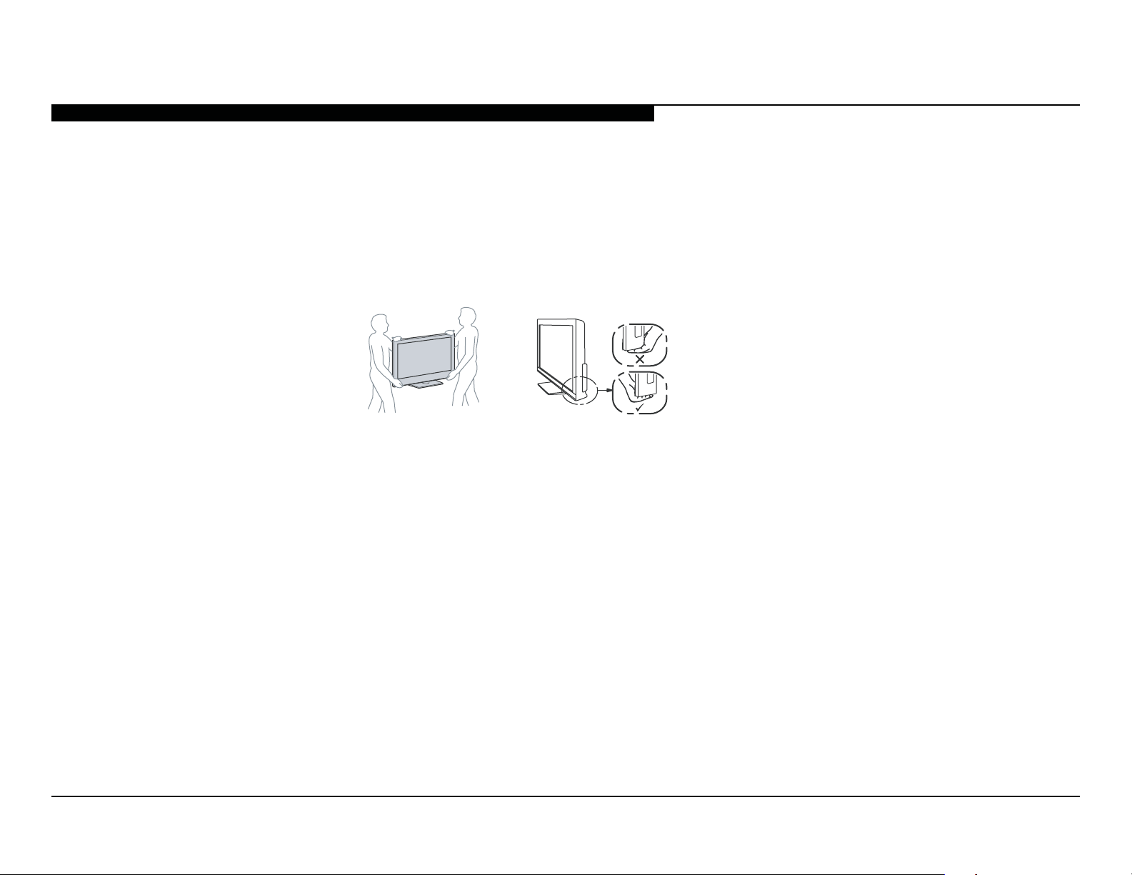
CARRYING THE TV
• Carry the TV with the adequate number of people; larger size TVs require two or more people.
• Correct hand placement while carrying the TV is very important for safety and to avoid
damage.
WARNING!!
An isolation transformer should be used during any service to avoid possible shock hazard, because of live chassis. The chassis of this
receiver is directly connected to the AC power line.
! SAFETY-RELATED COMPONENT WARNING!!
Components identi ed by shading and ! mark on the exploded views are critical for safe operation.
Replace all components with Sony parts whose part numbers appear as shown in this manual or in supplements published by Sony. It is
essential that all critical parts be replaced only with the part number speci ed in this manual to prevent electric shock, re, or other hazard.
Circuit adjustments that are critical for safe operation are identi ed in this manual.
Follow these procedures whenever critical components are replaced or improper operation is suspected.
NOTE: Do not modify the original design without obtaining written permission from the manufacturer or you will void the original parts and
labor guarantee.
KDL-32BX305/40BX405 3

SAFETY-RELATED WARNING
USE CAUTION WHEN HANDLING THE LCD PANEL
When repairing the LCD panel, be sure you are grounded by using a wrist band.
When installing the LCD panel on a wall, the LCD panel must be secured using the 4 mounting holes on the rear cover.
1) Do not press on the panel or frame edge to avoid the risk of electric shock.
2) Do not scratch or press on the panel with any sharp objects.
3) Do not leave the module in high temperatures or in areas of high humidity for an extended period of time.
4) Do not expose the LCD panel to direct sunlight.
5) Avoid contact with water. It may cause a short circuit within the module.
6) Disconnect the AC power when replacing the backlight (CCFL) or inverter circuit.
(High voltage occurs at the inverter circuit at 650Vrms.)
7) Always clean the LCD panel with a soft cloth material.
8) Use care when handling the wires or connectors of the inverter circuit. Damaging the wires may cause a short.
9) Protect the panel from ESD to avoid damaging the electronic circuit (C-MOS).
KDL-32BX305/40BX405 4

SAFETY CHECK-OUT
After correcting the original service problem, perform the following safety checks before releasing the set to the customer:
1. Check the area of your repair for unsoldered or poorly soldered connections.
Check the entire board surface for solder splashes and bridges.
2. Check the interboard wiring to ensure that no wires are “pinched” or touching
high-wattage resistors.
3. Check that all control knobs, shields, covers, ground straps, and mounting
hardware have been replaced. Be absolutely certain that you have replaced
all the insulators.
4. Look for unauthorized replacement parts, particularly transistors, that were
installed during a previous repair. Point them out to the customer and
recommend their replacement.
0.15 F
To Exposed Metal
Parts on Set
AC
Voltmeter
(0.75V)
5. Look for parts which, though functioning, show obvious signs of deterioration.
Point them out to the customer and recommend their replacement.
6. Check the line cords for cracks and abrasion. Recommend the replacement
of any such line cord to the customer.
7. Check the antenna terminals, metal trim, “metallized” knobs, screws, and
all other exposed metal parts for AC leakage. Check leakage as described
below.
Figure A. Using an AC voltmeter to check AC leakage.
Earth Ground
KDL-32BX305/40BX405 5
 Loading...