

Sony kdf 37h1000 schematic
HISTORY INFORMATION FOR THE FOLLOWING MANUAL:
SERVICE MANUAL
MODEL NAME REMOTE COMMANDER DESTINATION
KDF-37H1000
RM-YD014 US/CND
LA-5
CHASSIS
ORIGINAL MANUAL ISSUE DATE: 4/2007
:UPDATED ITEM
☛
REVISION DATE SUBJECT
4/2007 No revisions or updates are applicable at this time.
4/2007 Corrected Reference numbers for Fan and Fan Damper. Replaced page 71.
5/2007 Updated Self Diagnostic displays to include Lamp error. Replaced pages 8 & 9.
Added PN for 2P Connector Assembly (Thermal Fuse). Replaced pages 15 & 72.
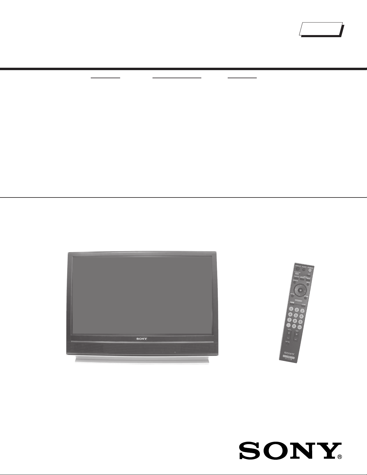
LCD PROJECTION TELEVISION
9-883-746-03
Self Diagnosis
Supported model
SERVICE MANUAL
MODEL NAME REMOTE COMMANDER DESTINATION
KDF-37H1000
RM-YD014 US/CND
LA-5
CHASSIS
9-883-746-03
KDF-37H1000 RM-YD014
LCD PROJECTION TELEVISION

KDF-37H1000
TABLE OF CONTENTS
SECTION TITLE PAGE SECTION TITLE PAGE
Specifi cations ................................................................................. 4
Warnings and Cautions .................................................................. 6
Safety Check-Out ........................................................................... 7
Self-Diagnostic Function ................................................................. 8
SECTION 1: DISASSEMBLY ............................................................... 10
1-1. Overview .............................................................................. 10
1-2. HAM Board Removal ............................................................11
1-3. Screen Frame Removal ........................................................11
1-3-1. Rear Cover Removal ..................................................11
1-3-2. Diffusion Plates (Screens) and
Screen Frame Assembly Removal .......................... 12
1-3-3. Diffusion Plates (Screens) Tape Method ................. 12
1-4. HB Board and Speaker Removal ......................................... 13
1-5. HCM Board Removal ........................................................... 13
1-6. Lamp Removal ..................................................................... 14
1-7. Lamp Duct Removal ............................................................. 15
1-8. Fan Exhaust Duct Removal ................................................. 16
1-9. Optical Unit Block Removal .................................................. 17
1-10. Chassis Remvoal ................................................................. 18
Wire Dressing ....................................................................... 19
SECTION 2: CIRCUIT ADJUSTMENTS .............................................. 32
2-1. Using the Remote Commander for Electrical Adjustments .. 32
2-2. Accessing Service Adjustment Mode ................................... 32
2-3. Viewing the Service Menus .................................................. 32
2-4. Using the Remote Commander to View Service Data ......... 33
2-4-1. Changing Service Data ............................................ 33
2-4-2. Exiting Service Mode ............................................... 33
2-5. Updating the Model Information when
Replacing the BM Board ...................................................... 33
2-5-1. Verifying Model Information ..................................... 34
2-6. Adjusting the Horizontal and vertical Settings ...................... 34
2-7. Resetting the Lamp .............................................................. 34
2-8. Verifying Service Data Changes .......................................... 34
2-9. Resetting to Factory Defaults ............................................... 35
SECTION 3: DIAGRAMS ..................................................................... 36
3-1. Circuit Boards Location ........................................................ 36
3-2. Printed Wiring Boards and
Schematic Diagrams Information ......................................... 36
3-3. Block Diagrams .................................................................... 38
Signal Flow Block Diagram .................................................. 38
Connection Diagram ............................................................ 39
3-4. Schematics and Supporting Information .............................. 40
BM Board Schematic Diagram (1 of 12) .............................. 40
BM Board Schematic Diagram (2 of 12) .............................. 41
BM Board Schematic Diagram (3 of 12) .............................. 42
BM Board Schematic Diagram (4 of 12) .............................. 43
BM Board Schematic Diagram (5 of 12) .............................. 44
BM Board Schematic Diagram (6 of 12) .............................. 45
BM Board Schematic Diagram (7 of 12) .............................. 46
BM Board Schematic Diagram (8 of 12) .............................. 47
BM Board Schematic Diagram (9 of 12) .............................. 48
BM Board Schematic Diagram (10 of 12) ............................ 49
BM Board Schematic Diagram (11 of 12) ............................. 50
BM Board Schematic Diagram (12 of 12) ............................ 51
G Board Schematic Diagram (1 of 2) ................................... 54
G Board Schematic Diagram (2 of 2) ................................... 55
HAM Board Schematic Diagram .......................................... 58
HB Board Schematic Diagram ............................................. 60
HCM Board Schematic Diagram .......................................... 62
S Board Schematic Diagram ................................................ 64
T Board Schematic Diagram ................................................ 65
U Board Schematic Diagram ................................................ 66
3-5. Semiconductors ................................................................... 69
SECTION 4: EXPLODED VIEWS ........................................................ 70
4-1. Screen Frame and Mirror Assemblies .................................. 70
4-2. Chassis and Optical Block Assembly ................................... 71
4-3. Connectors ........................................................................... 72
SECTION 5: ELECTRICAL PARTS LIST ............................................ 73
KDF-37H1000
APPENDIX A: ENCRYPTION KEY COMPONENTS ..........................A-1
APPENDIX A: REPLACING THE LAMP ............................................B-1
3
SPECIFICATIONS
p
)
p
b
a
KDF-37H1000
Power Requirements
Power Consumption (W)
In Use (Max)
In Standby
Inputs/Outputs
120V, 60Hz
200W
Less than 0.8W
HDMI IN 1/2
Video - 480i, 480p, 720p, 1080i, 1080p, PC timing
Audio - Two channel linear PCM 32, 44.1 and 48 kHz,
16, 20, and 24 bit
Audio - (HDMI IN 2 only) 500 mVrms
(100% modulation) Impedance:47 kilo ohms
Video (IN) 1/2/3
Video
1 total Y: 1.0 Vp-p, 75ohms unbalanced,
sync negative
S Video (IN)
1 total (4-pin mini DIN)
Y: 1Vp-p, 75ohms unbalanced, sync negative
C: 0.286Vp-p (Burst signal), 75ohms
Audio (IN)
500 mVrms (100% modulation)
Impedance:47 kilo ohms
Component In 1/2/3
) (Component Video)
(Y, P
B/CB
Y: 1.0 Vp-p, 75 ohms unbalanced, sync negative
:
0.7 Vp-p, 75 ohms;
P
B
PR: 0.7 Vp-p, 75 ohms
Audio (IN)
500 mVrms (100% modulation)
Impedance:47 kilo ohms
Audio Out
500 mVrms (100% modulation) Up to 2 Vrms at the
maximum volume setting (Varies with input level)
Digital Audio Optical Output (PCM/Dolby Digital)
Optical Rectangular
KDF-37H1000
eaker Output(W
S
S
eaker Dimension
Dimensions (W x H x D)
Mass
Trademark Information
As an ENERGY STAR® Partner, Sony
Corporation has determined that this product
meets the ENERGY STAR
®
guidelines for
energy efficiency.
ENERGY STAR
®
is a U.S. registered mark.
Blu-ray Disc is a trademark.
“BRAVIA” and , BRAVIA ENGINE EX, “XMB”
and “XrossMediaBar”, S-Force, BRAVIA Theatre Sync, , DM
BRAVIA Internet Video Link Ready and “PS3” are trademarks
or registered marks of Sony Corporation and/or
Sony Computer Entertainment Inc.
KDF-37H1000
12W + 12W
mm 65 x 130 mm
in
2
9/16
x 5
1/8
in
mm 899 x 663 x 342 mm
in
35
7/16
x 26
1/8
x 13
1/2
in
kg 20 kg
lbs 44.2 lbs
This TV is manufactured under license from Dol
Laboratories. “Dolby” and the double-D symbol
trademarks of Dolby Laboratories.
This TV incorporates High-
™
(HDMI
) technology. HDMI, the HDMI logo and HighDefinition Multimedia Interface are trademarks or
registered trademarks of HDMI Licensing LLC.
x
,
Macintosh is a trademark licensed to Apple Computer, Inc.,
registered in the U.S.A and other countries.
Definition Multimedia Interface
Design and specifi cations are subject to change without notice.
4

Television system
American TV standard, NTSC
ATSC Compliant 8VSB, ATSC (8VSB terrestrial)
ANSI/SCTE 07 2000, QAM on cable
Channel coverage
Terrestrial 2-69/ Cable TV: 1-125 (analog)
Terrestrial 2-69/ Cable TV: 1-135 (digital)
Screen Size (measured diagonally)
37 inches
Antenna
75-ohm external antenna terminal for VHF/UHF
Projection System
3 LCD Panels, 1 lens projection system
LCD Panel System
LCD (Liquid Crystal Display) Panel
KDF-37H1000
LCD Panel
0.73 inch TFT LCD panel (1,280 x 720 pixels)
Projection Lens
High Performance, large diameter hybrid lens F2.4
Lamp
100W, XL-2500 Ultra High Pressure Lamp
Supplied Accessories
Remote Commander RM-YD014
Two Size AA (R6) Batteries
Operating Instructions
Quick Setup Guide
Warranty Card
Online Registration Card
Optional Accessories
Connecting Cables
Lamp
XL-2500 Ultra High Pressure Lamp
KDF-37H1000
5
KDF-37H1000
WARNINGS AND CAUTIONS
CAUTION
These servicing instructions are for use by qualifi ed service personnel only. To reduce the risk of electric shock, do not perform any servicing other
than that contained in the operating instructions unless you are qualifi ed to do so.
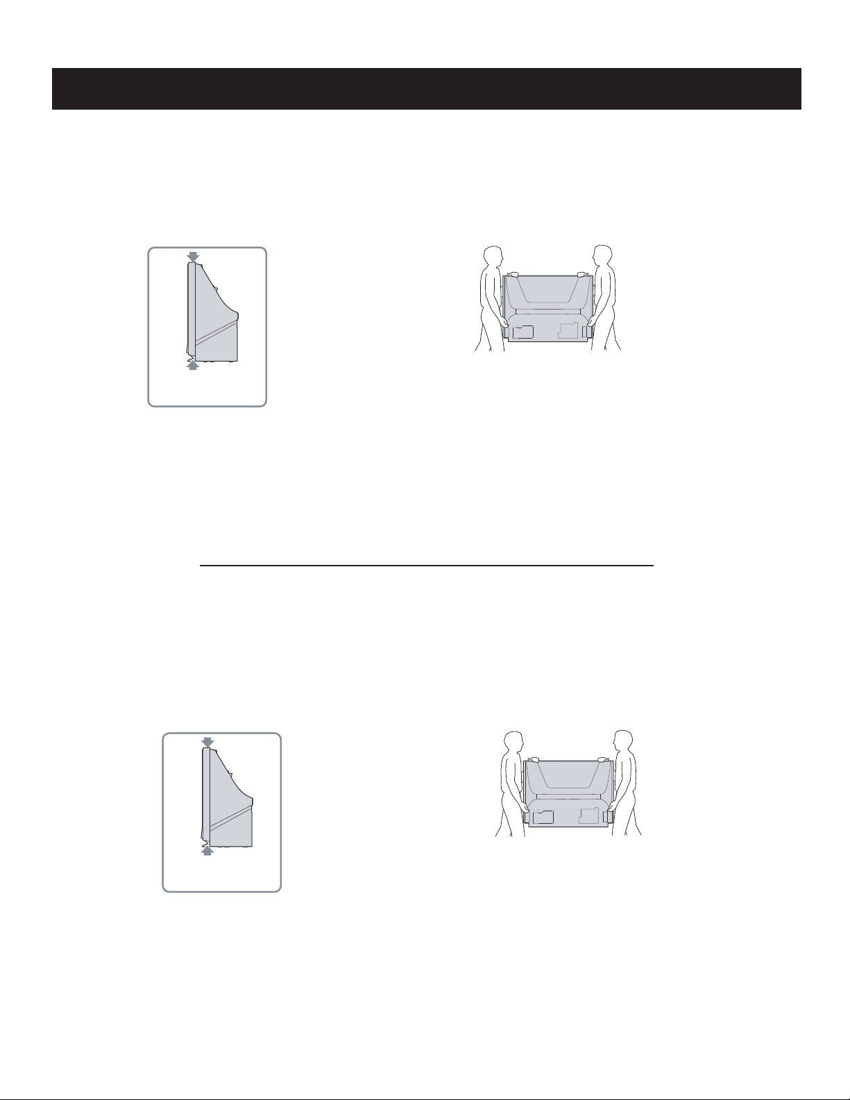
CARRYING THE TV
Carrying the TV requires at least two people. Do not hold
by the pedestal or the front panel of the TV. Doing so may
cause these parts to break off.
When moving the TV, place one hand in the hole on the
lower portion of the TV while grasping the top with the other
hand, as shown in the illustration below.
Do not grasp the
pedestal or the front
panel of the TV.
If you have connected cables and cords, be sure to
unplug them before moving the TV.
WARNING!!
An isolation transformer should be used during any service to avoid possible shock hazard, because of live chassis. The chassis of this receiver is
directly connected to the AC power line.
! SAFETY-RELATED COMPONENT WARNING!!
Components identifi ed by shading and ! mark on the schematic diagrams, exploded views, and in the parts list are critical for safe operation. Replace
these components with Sony parts whose part numbers appear as shown in this manual or in supplements published by Sony. Circuit adjustments that
are critical for safe operation are identifi ed in this manual. Follow these procedures whenever critical components are replaced or improper operation is
suspected.
ATTENTION!!
Ces instructions de service sont à l’usage du personnel de service qualifi é seulement. Pour prévenir le risque de choc électrique, ne pas faire
l’entretien autre que celui contenu dans le Mode d’emploi à moins que vous soyez qualifi é faire ainsi.
TRANSPORTER LE TÉLÉVISEUR
Le transport du téléviseur doit être effectué par au
moins deux personnes. Ne tenez pas le téléviseur
par son socle ni par le panneau avant. Ces pièces
risqueraient de se détacher.
Lorsque vous déplacez le téléviseur, placez une
main dans l’orifice de la partie inférieure du
téléviseur tout en tenant la partie supérieure de
l’autre main, comme illustré ci-dessous.
Ne tenez pas le
téléviseur par son socle
ni par le panneau avant.
Afi n d’eviter tout risque d’electrocution provenant d’un chássis sous tension, un transformateur d’isolement doit etre utilisé lors de tout dépannage. Le
chássis de ce récepteur est directement raccordé à l’alimentation du secteur.
Si vous avez branché les câbles et les cordons
d’alimentation, veillez à les débrancher avant de
déplacer le téléviseur.
! ATTENTION AUX COMPOSANTS RELATIFS A LA SECURITE!!
Les composants identifi es par une trame et par une marque ! sur les schemas de principe, les vues explosees et les listes de pieces sont d’une
importance critique pour la securite du fonctionnement. Ne les remplacer que par des composants Sony dont le numero de piece est indique dans le
present manuel ou dans des supplements publies par Sony. Les reglages de circuit dont l’importance est critique pour la securite du fonctionnement
sont identifi es dans le present manuel. Suivre ces procedures lors de chaque remplacement de composants critiques, ou lorsqu’un mauvais
fonctionnement suspecte.
KDF-37H1000
6
SAFETY CHECK-OUT
KDF-37H1000
After correcting the original service problem, perform the following
safety checks before releasing the set to the customer:
1. Check the area of your repair for unsoldered or poorly soldered
connections. Check the entire board surface for solder splashes and
bridges.
2. Check the interboard wiring to ensure that no wires are “pinched” or
touching high-wattage resistors.
3. Check that all control knobs, shields, covers, ground straps, and
mounting hardware have been replaced. Be absolutely certain that
you have replaced all the insulators.
4. Look for unauthorized replacement parts, particularly transistors,
that were installed during a previous repair. Point them out to the
customer and recommend their replacement.
5. Look for parts which, though functioning, show obvious signs of
deterioration. Point them out to the customer and recommend their
replacement.
6. Check the line cords for cracks and abrasion. Recommend the
replacement of any such line cord to the customer.
7. Check the B+ and HV to see if they are specifi ed values. Make sure
your instruments are accurate; be suspicious of your HV meter if sets
always have low HV.
8. Check the antenna terminals, metal trim, “metallized” knobs, screws,
and all other exposed metal parts for AC leakage. Check leakage as
described below.
Leakage Test
The AC leakage from any exposed metal part to earth ground and
from all exposed metal parts to any exposed metal part having a
return to chassis, must not exceed 0.5 mA (500 microamperes).
Leakage current can be measured by any one of three methods.
1. A commercial leakage tester, such as the Simpson 229 or RCA
WT-540A. Follow the manufacturers’ instructions to use these
instructions.
2. A battery-operated AC milliampmeter. The Data Precision 245
digital multimeter is suitable for this job.
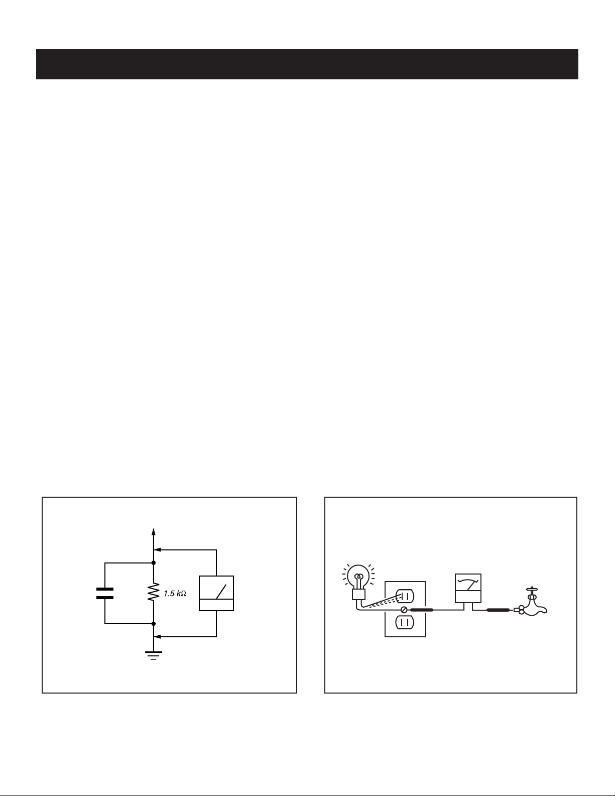
3. Measuring the voltage drop across a resistor by means of a VOM
or battery-operated AC voltmeter. The “limit” indication is 0.75
V, so analog meters must have an accurate low voltage scale.
The Simpson’s 250 and Sanwa SH-63TRD are examples of
passive VOMs that are suitable. Nearly all battery-operated digital
multimeters that have a 2 VAC range are suitable (see Figure A).
How to Find a Good Earth Ground
A cold-water pipe is a guaranteed earth ground; the cover-plate
retaining screw on most AC outlet boxes is also at earth ground. If the
retaining screw is to be used as your earth ground, verify that it is at
ground by measuring the resistance between it and a cold-water pipe
with an ohmmeter. The reading should be zero ohms.
If a cold-water pipe is not accessible, connect a 60- to 100-watt
trouble- light (not a neon lamp) between the hot side of the receptacle
and the retaining screw. Try both slots, if necessary, to locate the hot
side on the line; the lamp should light at normal brilliance if the screw
is at ground potential (see Figure B).
0.15 μF
Figure A. Using an AC voltmeter to check AC leakage. Figure B. Checking for earth ground.
KDF-37H1000
To Exposed Metal
Parts on Set
Earth Ground
AC
Voltmeter
(0.75V)
Trouble Light
AC Outlet Box
Ohmmeter
Cold-water Pipe
7
KDF-37H1000
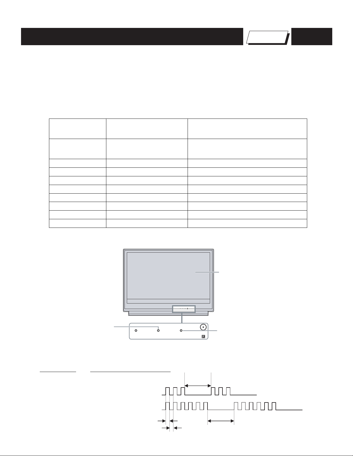
SELF-DIAGNOSTIC FUNCTION
The units in this manual contain a self-diagnostic function. If an error occurs, the POWER/STANDBY will automatically begin to fl ash. The number of
times the LED fl ashes translates to a probable source of the problem. A defi nition of the POWER/STANDBY fl ash indicators is listed in the instruction
manual for the user’s knowledge and reference. If an error symptom is diffi cult to reproduced use the Remote Commander to display the record that is
stored at the internal NVM to specify the cause of the failure.
Diagnostic Test Indicators
When an error occurs, the POWER/STANDBY will fl ash a set number of times to indicate the possible cause of the problem. If there is more than
one error, the POWER/STANDBY will identify the fi rst of the problem areas. If the errors occur simultaneously, the one that corresponds to the fewest
fl ashes is identifi ed fi rst.
Results for all of the following diagnostic items are displayed on screen. (No error has occurred if the screen displays a “0”.)
Self Diagnosis
Supported model
Number of times
LED indicator
flashes Diagnosis Item Probable Cause
Lamp not seated properly
☛
1 Lamp Error
(Note: The lamp LED will flash red when
this error occurs, not the Power LED)
2 OVP 10.5V is high on B Board
3 LowB Error 10.5V is low on B Board
4 Not Used in this model
5 HV Detect Ballast is not working
6 Lamp Cover/ Lamp Position The Lamp cover is not closed securely.
7 Temp Error High Temperature or sensor connection
8 Audio Error DC error on U Board
9 Fan Error Fan is not working properly
DISPLAY OF POWER/STANDBY OR LAMP LED FLASH COUNT
Screen
TIMER LAMP POWER
Flashes red for Lamp error
TIMER LAMP POWER
Flashes red for all except Lamp error
- 4 Flash is not used for self-diagnosis
-Example
Diagnosis
LowB Error
Number of times LED Flashes
LED OFF
3.0sec
3 times
Lamp Cover 6 times
KDF-37H1000
LED ON : 0.3sec
LED OFF : 0.3sec
LED OFF
3.0sec
8
KDF-37H1000
RELEASING THE POWER/STANDBY LED FLASH
Unplug the power cord from the outlet to temporarily stop the POWER/STANDBY lamp from fl ashing.
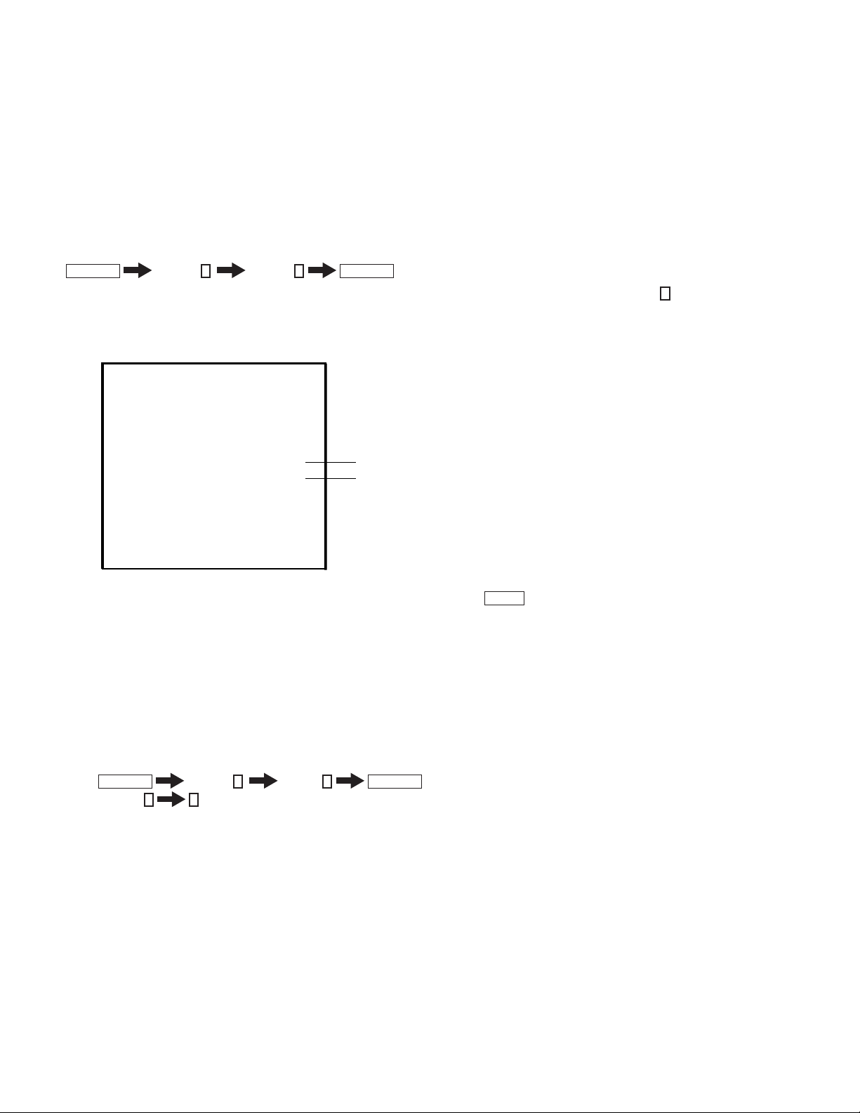
Self-Diagnostic Screen Display
For failures that are diffi cult to reproduce, or accompany occasional power off and/or picture mute, the Self-Diagnostic screen display is useful to
specify the cause.
VIEWING THE SELF-DIAGNOSTIC SCREEN
1. TV must be in standby mode. (Power off).
2. Press the following buttons on the Remote Commander within a second of each other:
DISPLAY
NOTE: This differs from the method of accessing service mode which is Volume
Sample Self-Diagnostic Screen Display
☛
Channel
1 : LAMP_ERR 0
2 : OVP 0
3 : LowB-ERROR 0
5:
6:
7 : TEMP-ERROR
8 : AUDIO-ERROR 0
9 : FAN-ERROR 0
5
Volume -
SELF CHECK
HV DETECT
LAMP_COVER 1
0
0
POWER
+
"1" is displayed when an error is detected one or more times
"0" is displayed when no error has been detected
Name: KDF-37H1000
Serial: XXXXXXXXXX
NOTE: To refresh the Self Check menu when all the items are not displayed, press
3. Proceed to Viewing the Self-Diagnostic Errors.
JUMP
on the Remote Commander.
CLEARING THE SELF-DIAGNOSTIC SCREEN
The self-diagnostic results displayed on the screen are not cleared automatically, therefore you should always check the self-diagnostic screen during
repairs. When you have completed the repairs, clear the self-diagnostic screen to reset the results to “0”.
Note: The self-diagnostic function will not be able to detect any subsequent faults after completion of the repairs unless the Self-Diagnostic
result display is cleared to reset the results to “0”.
1. If the Self-Diagnostic screen is already displayed, proceed to step 3. If not, Power off (Set to Standby mode).
2. Press
3. Press Channel 8
The status resets to 0.
4. To exit the Self-Diagnostic screen, turn the power off.
DISPLAY
Channel
0
5
Volume -
POWER
KDF-37H1000
9
1-1. OVERVIEW
TOOLS NEEDED
Long Phillips Screwdriver
Needle Nose Pliers
Small Flathead Screwdriver or Jewelers Screwdriver
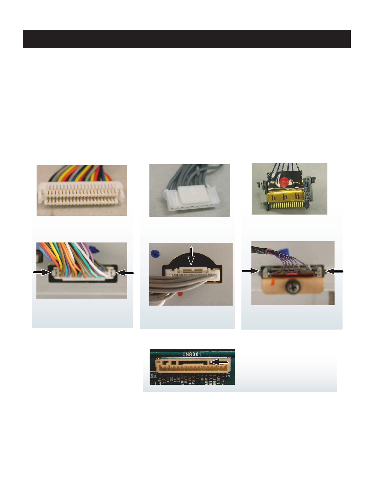
The connectors in this chassis have been redesigned to ensure they are securely fasten to the boards. Please review the illustrations below.
Use caution not to rock the Type 2 or Type 3 connectors when removing or reinstalling to avoid breaking the solder leads off the
Printed Circuit Boards.
KDF-37H1000
SECTION 1: DISASSEMBLY
TYPE 1
LIFT ONE SIDE AT A TIME
BY PUSHING TAB IN WITH
SMALL SCREWDRIVER
TYPE 2
SQUEEZE DOWN ON
TAB TO RELEASE
TYPE 3
SQUEEZE LOCKING TAB
TOWARDS CONNECTOR
BEFORE PULLING FREE
CAUTION! IF THE TYPE 2 FEMALE
CONNECTOR HAS A SLOT (AS SHOWN)
MAKE SURE THE LOCK TAB SEATS INSIDE
THIS SLOT.
KDF-37H1000
10
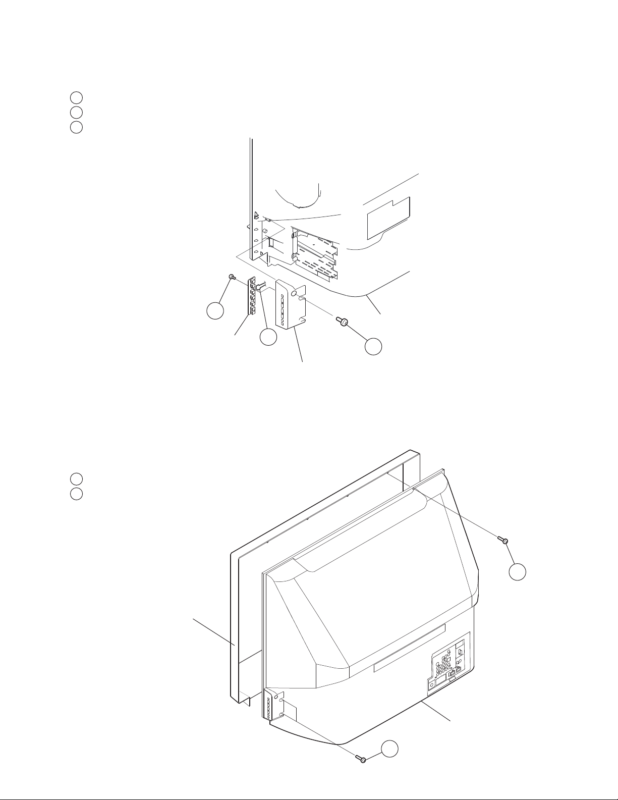
1-2. HAM BOARD REMOVAL
1
Remove one screw, +BVTP2 4X16
2
Disconnect a connector from HAM board
3
Remove 2 screws for HAM board removal,
+BVTP 3x12 TYPE2
KDF-37H1000
3
HAM PWB
1-3. SCREEN FRAME REMOVAL
All of the components of this model can be reached by removing the Screen Frame Assembly.
Caution:
When removing the Rear Cover or the Screen Frame
dust particles.
1-3-1. REAR COVER REMOVAL
1
Remove 10 screws, +BVTP2 4x16
2
Remove 4 screws from side brackets, +BVTP2 4x16
Rear Cover
2
1
Control Botton
Bracket
Assembly, be sure to clean the mirror and Diffusion Plate(s) to remove any
1
Screen Frame Assembly
KDF-37H1000
Rear Cover
2
11
KDF-37H1000
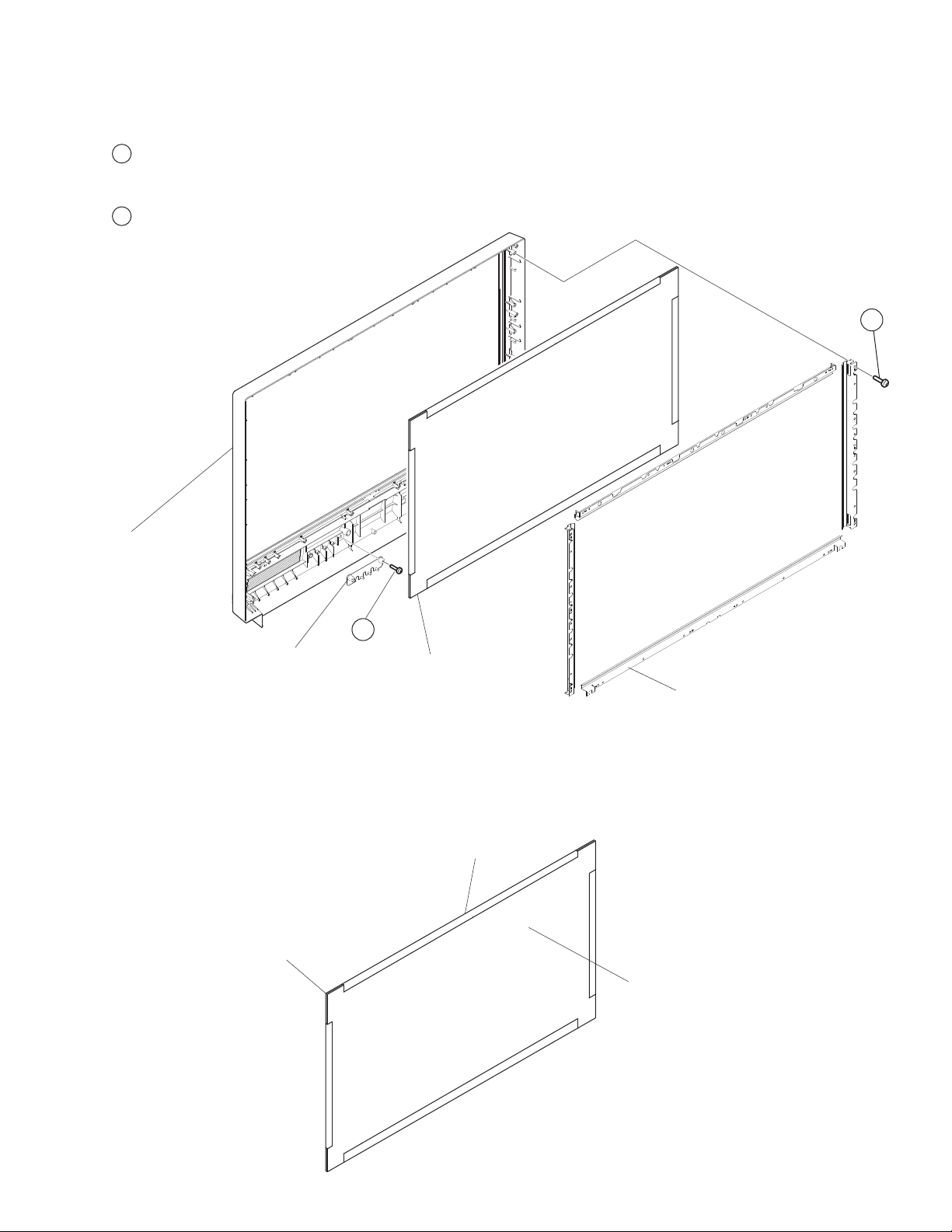
1-3-2. DIFFUSION PLATES (SCREENS) AND SCREEN FRAME ASSEMBLY REMOVAL
1
Remove 4 screws, +BVTP2 4x16
(3 screws on each side to remove the side brackets,
and 4 screws on the top and bottom brackets.)
2
Remove 1 screw, +BVTP 3x12, to remove Light Guide.
NOTE: The Light Guide is not included with the
Screen Frame Assembly.
1
Screen Frame Assembly
1-3-3. DIFFUSION PLATES (SCREENS) TAPE METHOD
NOTE: The following diagram illustrates the taping method when replacing the diffusion Plates.
For Part Numbers refer to the Exploded View section of this manual.
Light Guide
Diffusion Plate
(Lenticular - Front side)
2
Diffusion Plates
Screen Holder
Black Acetate Tape
Diffusion Plate
(Frensnel - Rear side)
KDF-37H1000
12
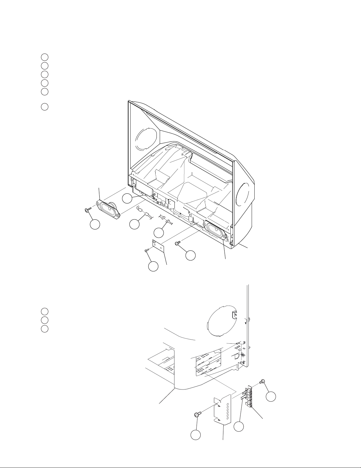
1-4. HB BOARD AND SPEAKER REMOVAL
1
Remove 5 screws from separator, +BVTP2 4x16
2
Disconnect connectors from HB board
3
Disconnect connectors from Speakers
4
Lift tabs and slide out separator unit.
5
Remove 2 screws for HB board removal,
+BVTP 3x12 TYPE2 IT-3
6
Remove 4 screws from speakers,
+BWTP2 4x16
Speaker
KDF-37H1000
6
1-5. HCM BOARD REMOVAL
1
Remove one screw, +BVTP2 4X16
2
Disconnect connectors from HCM board
3
Remove 2 screws for HCM board removal,
+BVTP 3x12 TYPE2
4
3
2
Rear Cover
1
HB PWB
5
Speaker
KDF-37H1000
3
Rear Cover
HC PWB
2
1
HC Bracket
13
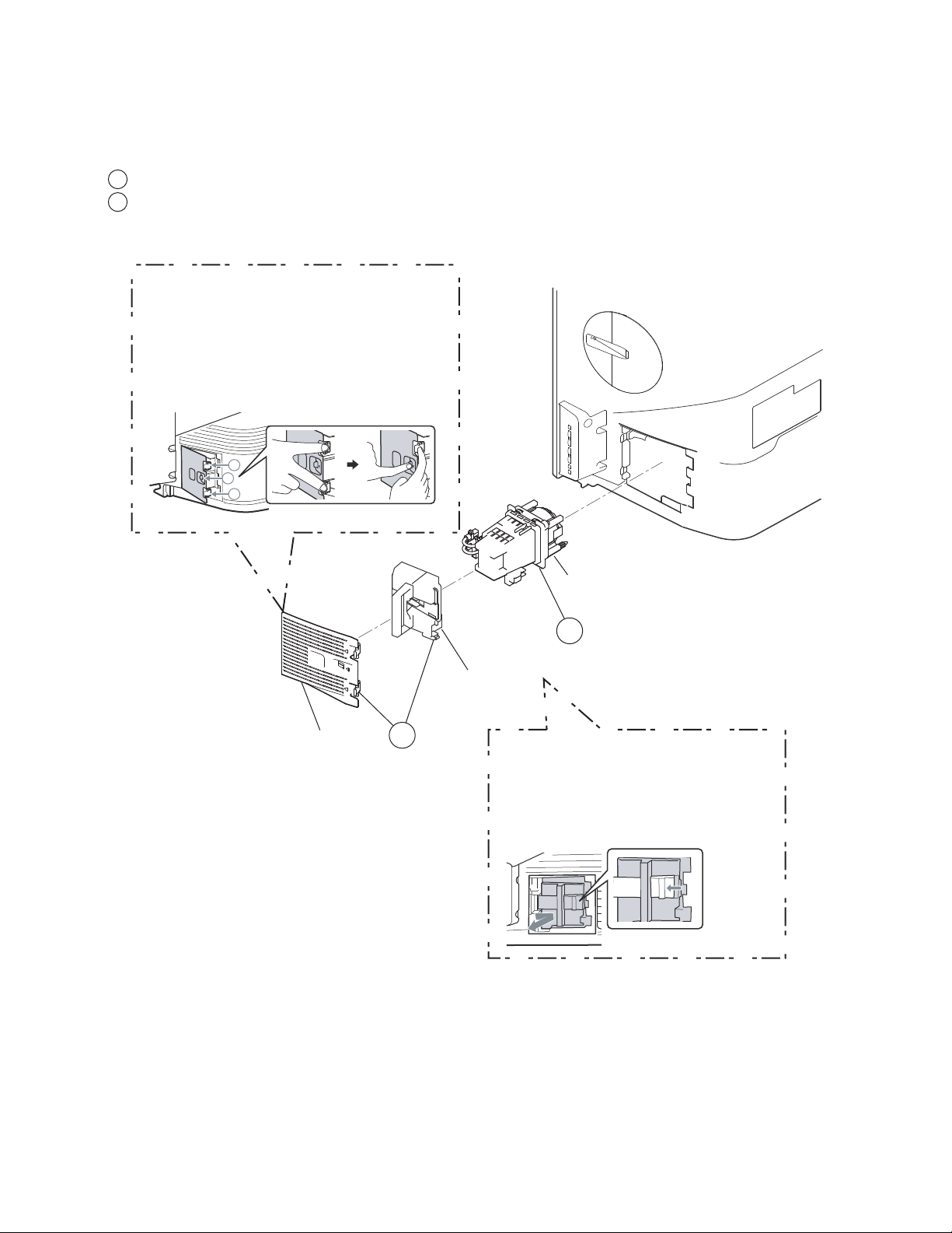
1-6. LAMP REMOVAL
For detailed instructions, refer to “Replacing the Lamp” in the Appendix section of this manual
1
Remove the Lamp Door and the Lamp Cover
2
Pull the lamp out of the TV
Using equal force, press both hooks (marked
by 1) towards the TV screen in the direction
the arrows are pointing.
While pressing the two hooks (marked by 1),
push the center lever (marked by 2) towards
the TV screen and pull the Lamp Cover towards
you. The lamp cover should come off easily.
1
2
1
KDF-37H1000
Lamp Cover
Lamp Block
2
Lamp Door
1
Remove the Lamp Door.
Holding the door knob, press the door lever
toward the door knob in the direction the
arrow is pointing. Then, pull the lamp door
out of the TV towards you.
KDF-37H1000
14
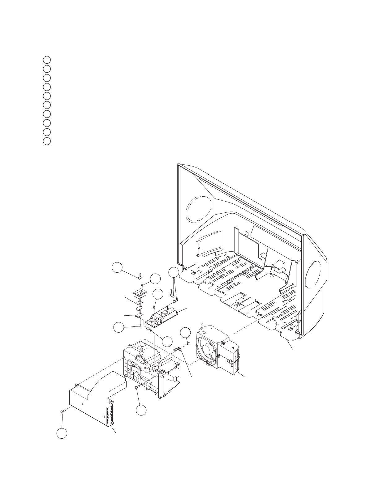
1-7. LAMP DUCT REMOVAL
1
Disconnect 4 connector joints (not shown)
2
Remove 2 screws, +BVTP2 4x16
3
Disconnect a connector from fuse box
4
Remove one screw, +BVTP 3x12 TYPE2 IT-3
5
Remove one screw, +BVTP 3x12 TYPE2 IT-3
6
Remove one screw, +BVTP 3x12 TYPE2 IT-3
7
Remove one screw, +BVTP 3x12 TYPE2 IT-3
8
Disconnect 2 connectors
9
Disconnect 2 connectors
10
☛
Disconnect 1 connector (Thermal Fuse)
KDF-37H1000
3
8
4
S PWB
Fuse Sheet
Fuse Plate
7
Power Board
5
9
10
☛
T PWB
Rear Cover
Fan and Exhaust ducts
6
2
Duct, Intake
KDF-37H1000
15
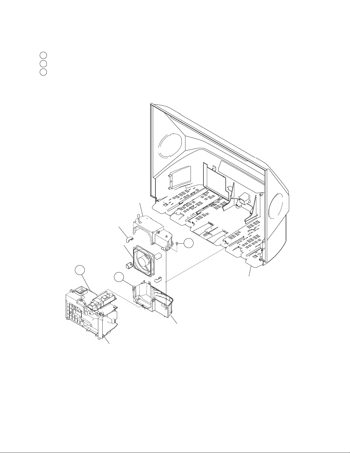
1-8. FAN EXHAUST DUCT REMOVAL
1
Release hook from Lamp Duct
2
Remove 2 screws, +BVTP2 4X16
3
Release three hooks to separate upper and lower duct
Caution:
When replacing the DC Fan be sure to remove any dust particles.
KDF-37H1000
Fan Cushion
1
Exhaust Duct(U)
Fan
3
Lamp Duct
2
Rear Cover
Exhaust Duct(L)
KDF-37H1000
16
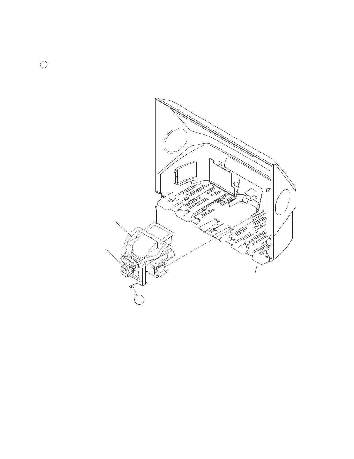
1-9. OPTICAL UNIT BLOCK REMOVAL
Use caution not to damage the lens when removing the Optical Unit Block Assembly
1
Remove 2 screws, +BVTP2 4x16
Caution:
When replacing the Optics Unit Block
Assembly be sure to remove any dust particles.
KDF-37H1000
Optical Unit
Block Assembly
If necessary,
gently cut the foam
above the connector cable
to detach from the
Optical Unti Block
Assembly.
NOTE: The connector is
NOT included with the
Optical Block Assembly.
Rear Cover
1
KDF-37H1000
17
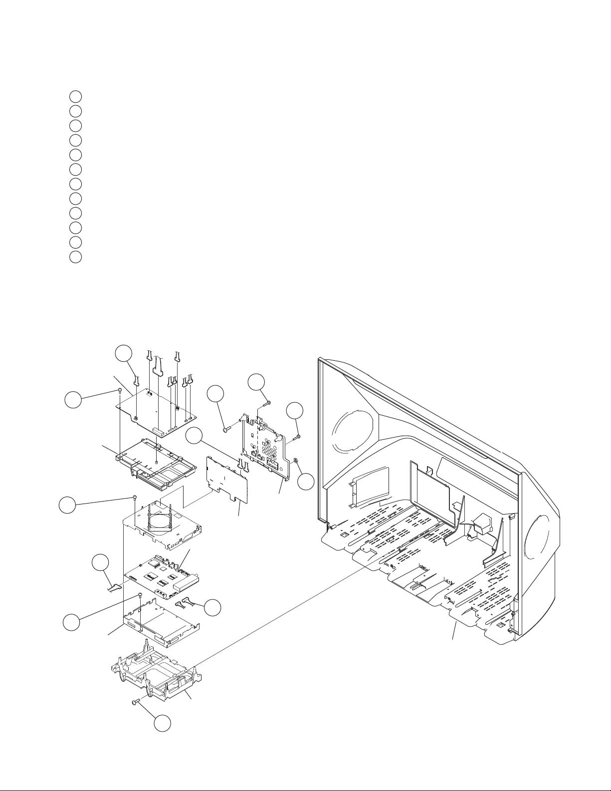
1-10. CHASSIS REMVOAL
1
Disconnect 8 connectors from G board
2
Disconnect a lead wire connector from B board
3
Disconnect 2 connectors from B board
4
Remove 2 screws, +BVTP2 4x16
5
Remove one screw, +BVTP 3x12 TYPE2 IT-3
6
Remove 3 screws, +PSW M3X8
7
Remove 6 screws, +BVTP 3x12 TYPE2 IT-3
8
Disconnect 2 connectors from U board
9
Remove 2 screws, SPECIAL (+PW 4X30)
10
Remove2 screws, +PSW M3X8
11
Remove 2 screws, +BVTP 3x12 TYPE2 IT-3
12
Remove 1 washer hexagon nut from tuner
Caution:
When replacing any part of the chassis be sure to remove any dust particles and clean the mirror
KDF-37H1000
.
G Board
7
G Bracket
6
5
B-Shield
1
10
9
11
8
12
Terminal
Bracket
U Board
B Board
2
3
Rear Cover
KDF-37H1000
Main Base
4
18
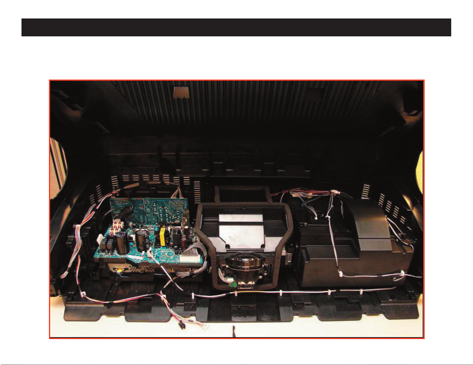
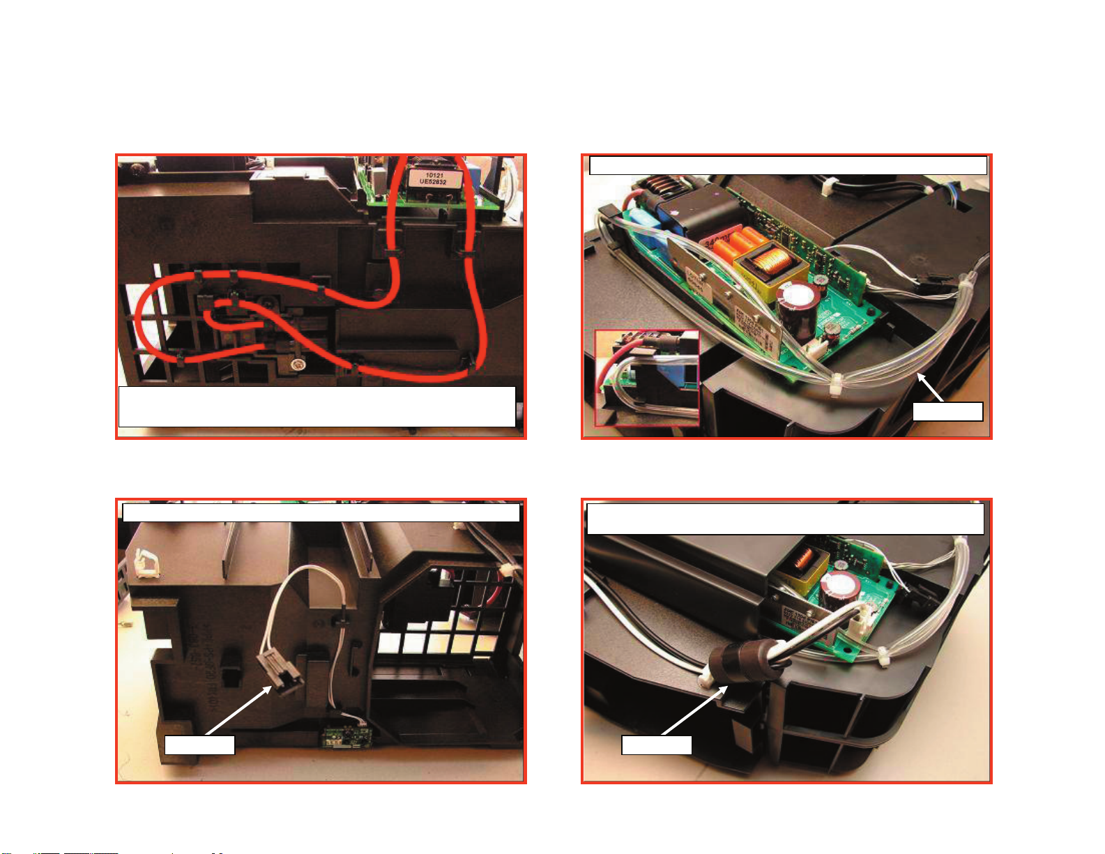
WIRE DRESSING
COMPLETE INTERNAL WIRE DRESSING
KDF-37H1000
KDF-37H1000
19
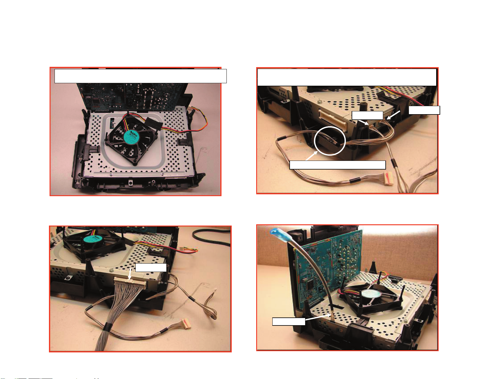
B BLOCK ASSEMBLY
KDF-37H1000
After installing Fan add Himelon Tape as shown below
Install 8P IRIS and 9P HB joint connector assy and wire dress
as shown
191003515
191003514
Wire dress into hook on Main Bracket
KDF-37H1000
191003507
191003507
20
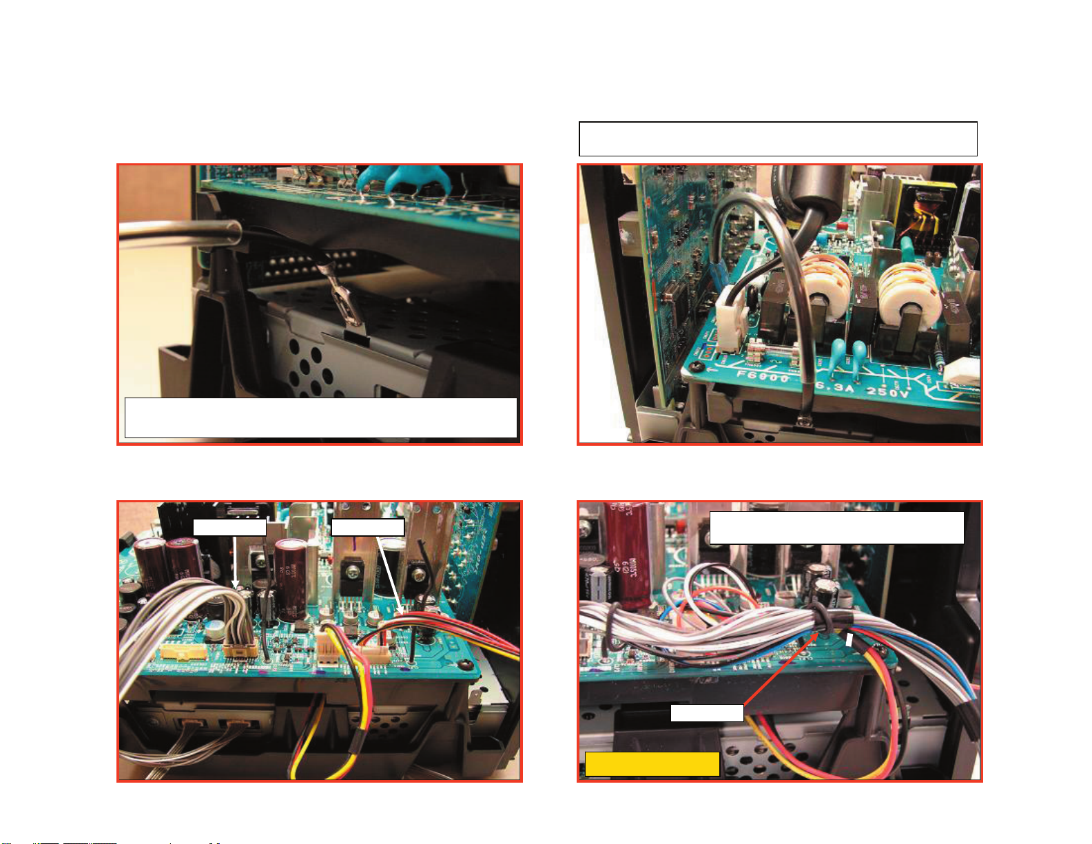
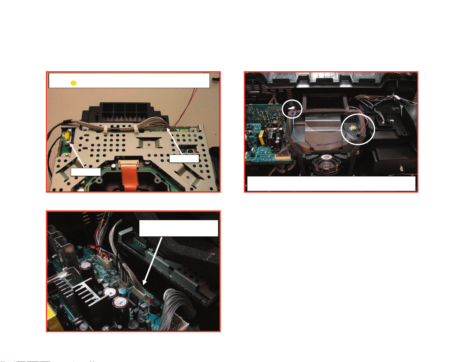
CHASSIS ASSEMBLY
Before Installing [G] Board it may be necessary to bend tab slightly in
order to properly install [G] board.
KDF-37H1000
Lighting ground should be behind AC cord. UL Tube should be located
on [G] board side of connection as shown below
KDF-37H1000
191003519 191003520
ONLY Wire dress 3P Fan Connector to wire
holder on (1) side of wire as shown below.
Wire Pin
CRITICAL FOR EMI
21
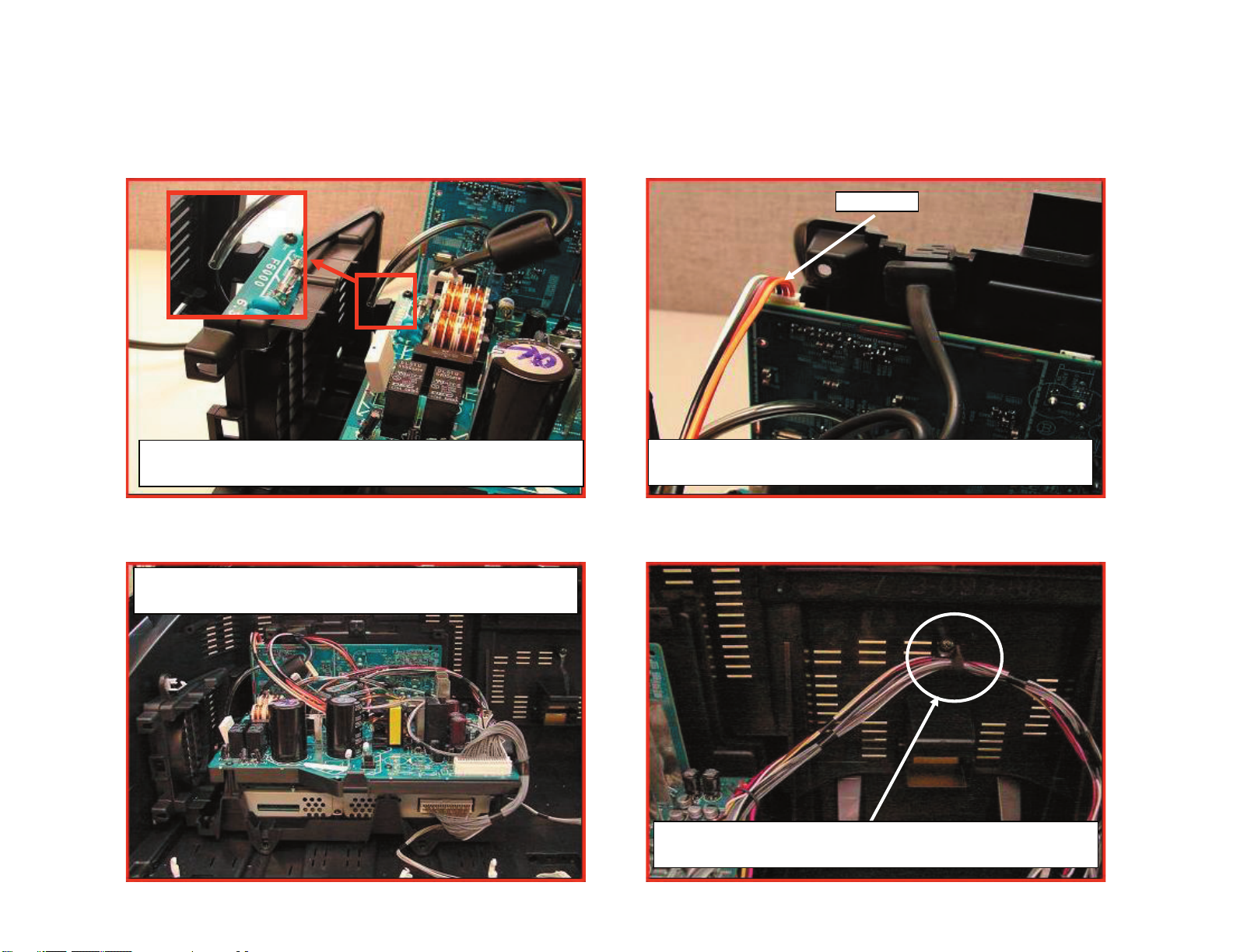
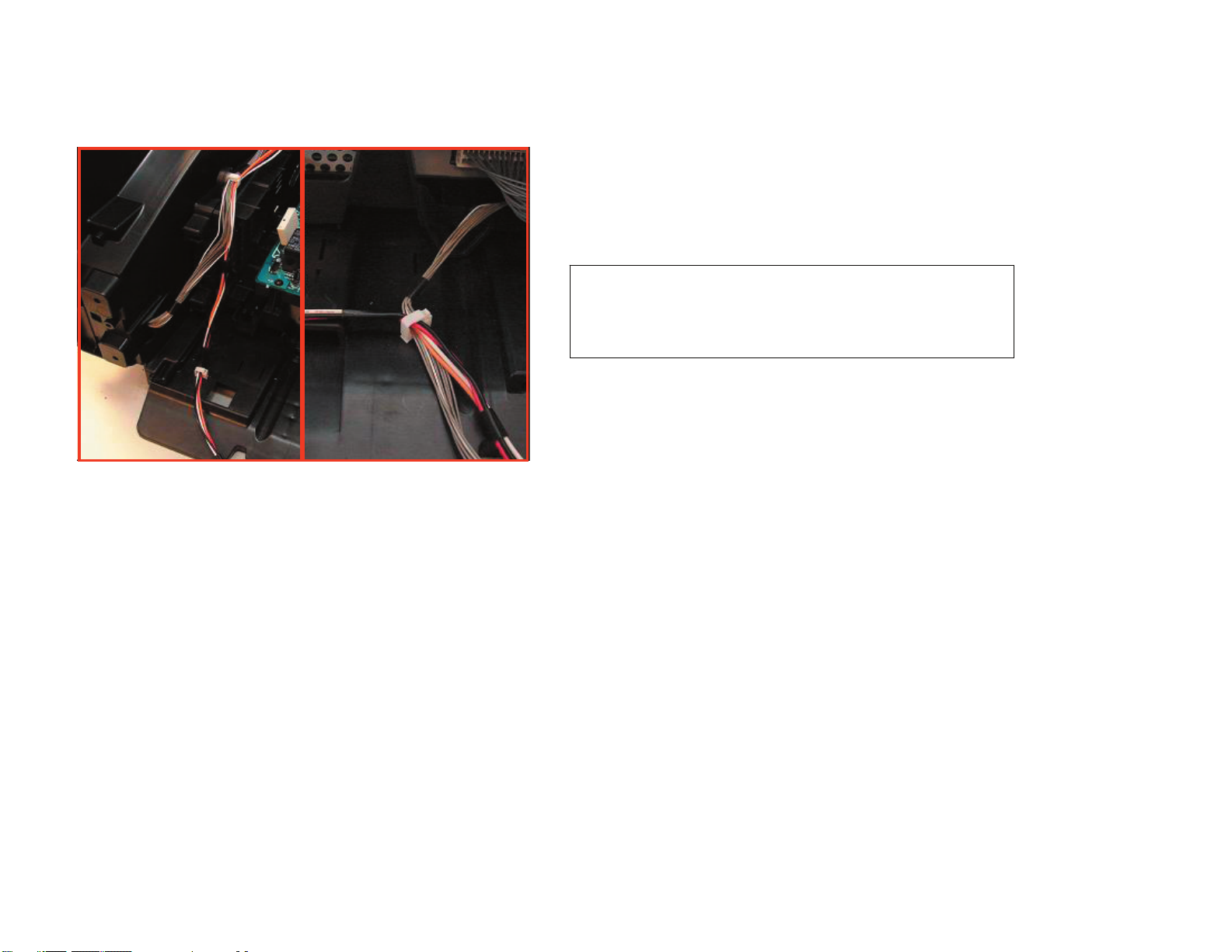
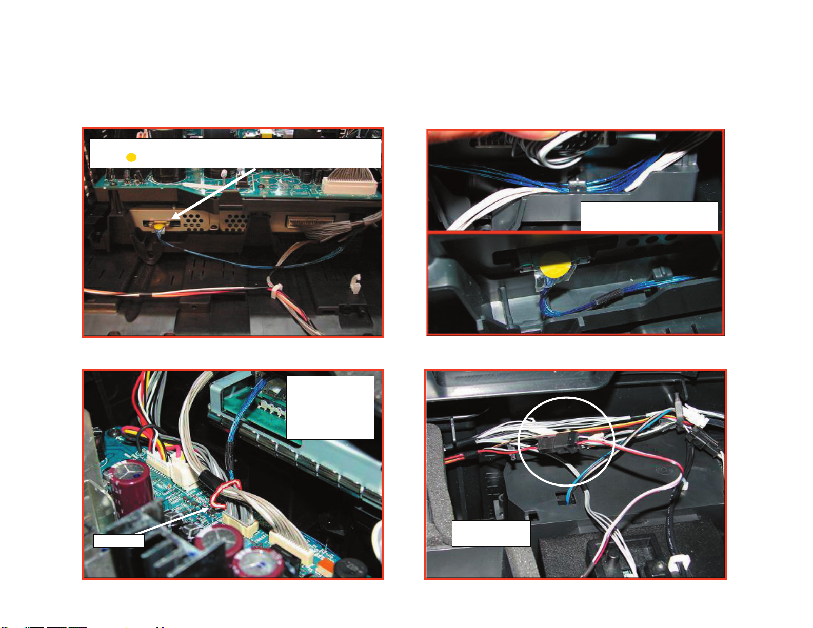
CHASSIS ASSEMBLY (CONTINUED)
KDF-37H1000
191003512
Lighting Ground should be inside of Fan Bracket as shown
Install Chassis Assy to Rear Cabinet
KDF-37H1000
Install 4P Speaker Connector Assy to [U]
Route and Dress 9P and 20P Connecto r Assy to Rear Cabinet as
shown above.
22
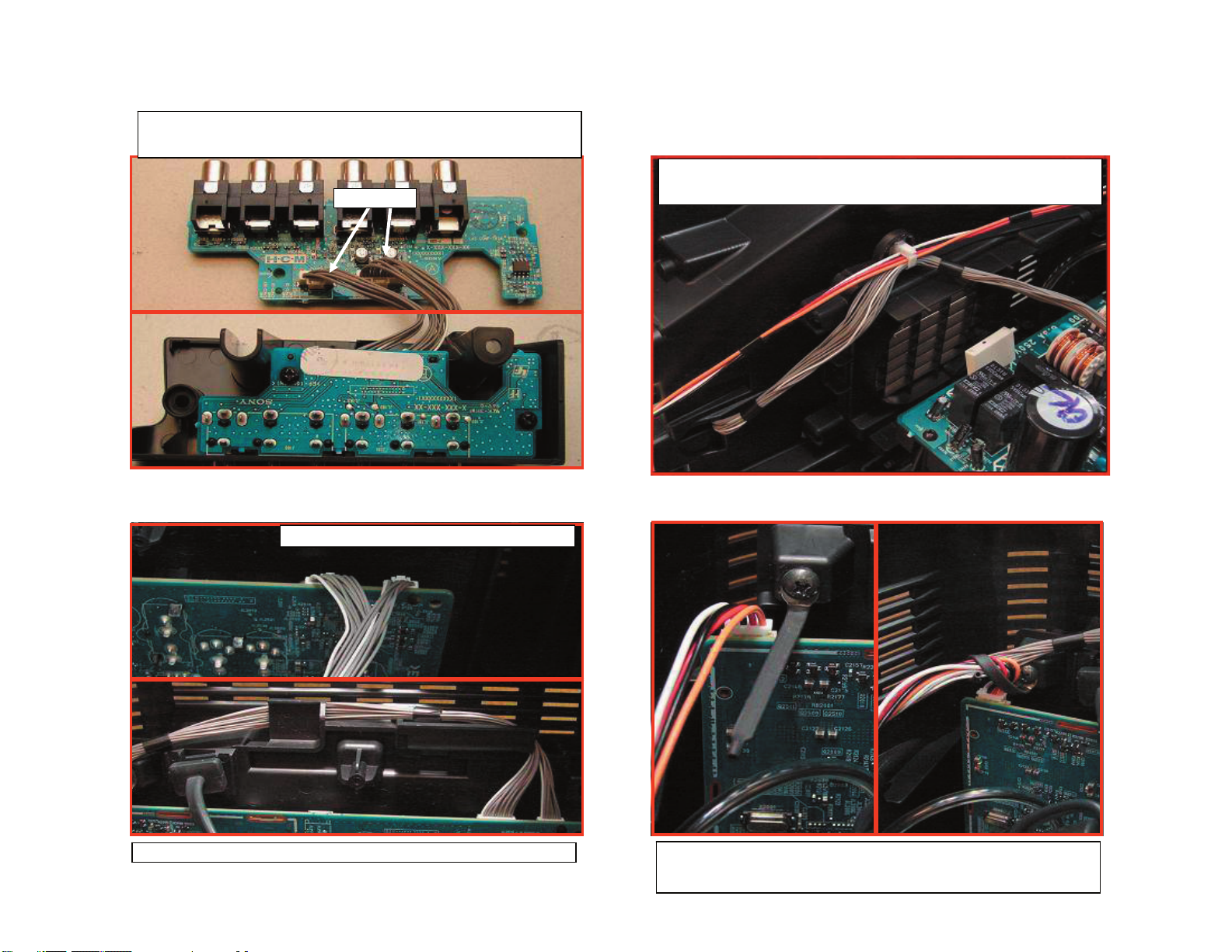
()
CHASSIS ASSEMBLY (CONTINUED)
HCM connector assy must be installed to [HCM] board before
installing board to HC Bracket
191003507
KDF-37H1000
After Installing HC Bracket w/ [HCM] board to Rear Cabinet Route
HCM connector Assy and 4P Speaker Conn Assy to Fan Bracket.
After Installing Route above terminal bracket as shown above.
KDF-37H1000
Install 8P/12P Connector from [HCM] to [U]
Wire Dress 4P Speaker Connector and 12P/8P HC connector assy to
wire holder. Bend wire Holder as necessary to take up "slack" in
cables.
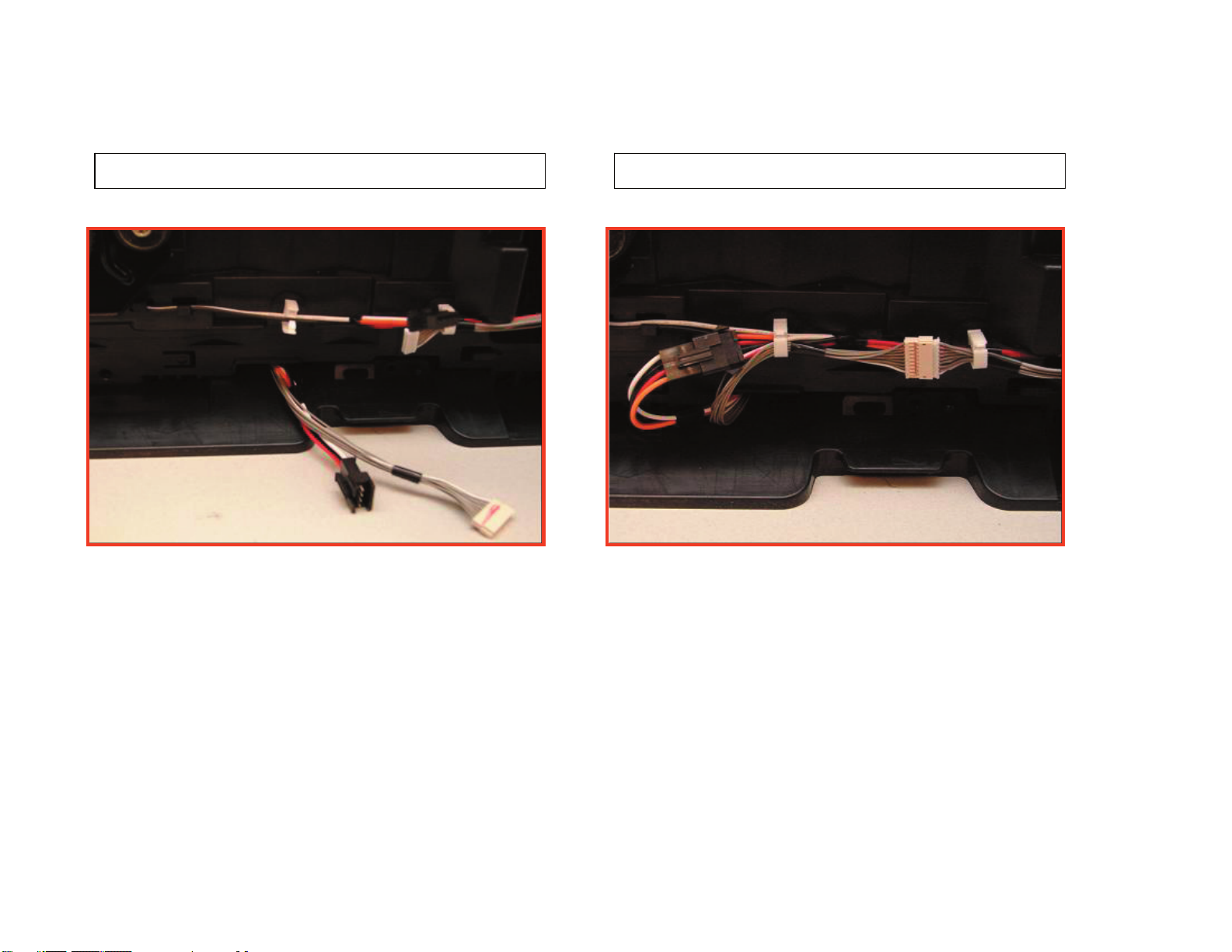
23
SPEAKER WIRE ASSEMBLY
Fig. 1 Fig. 2
KDF-37H1000
Route 4P Speaker to Wire Holder as shown in Fig 1.
Then Route 4P Speaker and 9P [HB] connectors to wire holder shown
in fig.2
KDF-37H1000
24
SPEAKER WIRE ASSEMBLY AND HB BOARD
KDF-37H1000
When Installing Seperator Block Assy ensure that the Speaker and
[HB] Connectors are not pinched and routed as below.
After connecting 9P[HB] and 4P Speaker Connector wire dress to
Holder Wire as shown below
KDF-37H1000
25
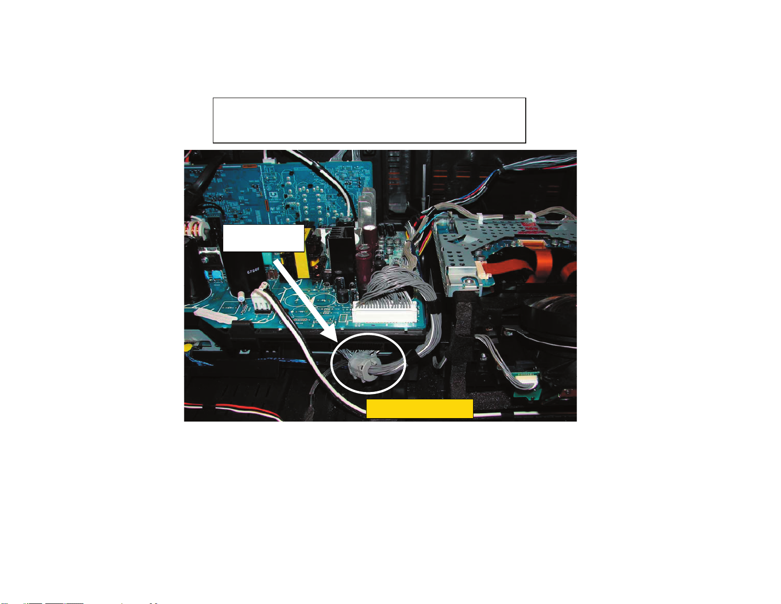
FERRITE CORE INSTALLATION
KDF-37H1000
Install Ferrite Core ZCAT2017-0930 Sony P/N 1-500-484-21 to the
following connector assys as shown below
Ferrite Core
p/n 1-500-484-21
KDF-37H1000
CRITICAL FOR EMI
26
POWER SUPPLY BLOCK (BALLAST)
Lamp Connector from Ballast MUST be kept from Crossing. Please
follow above wire dressing.
KDF-37H1000
Route 7P Ballast Control Conn Assy as shown below.
191003518
T BOARD
Route 7P Ballast Control Conn Assy as shown below.
KDF-37H1000
S BOARD
Install 3P Ballast Power as shown below and wire dress to Holder
Wire.
191003517 191003509
27

DUCT BLOCK ASSEMBLY
Wired Dress 3P
Ballast Power to
hooks on Duct Block
as shown to the right.
KDF-37H1000
Install Duct Block Assy to Rear Cabinet and Route 3P Ballast power
Connector as shown to Holder Wire on Rear Cabinet
Ensure 9P ballast
Connector is wire
dressed as shown to
the right
KDF-37H1000
Connect 9P Ballast/2P thermal sensor/3P [T] and 3P Duct Blk Fan
Connector and dress to wire holders as shown. Do Not close
Completely wire holders.
28
OPTICAL UNIT BLOCK ASSEMBLY
Install 21P LVDS and 15P[C] to [G] as shown below. Yellow
Sticker should be facing towards center of [C] board.
183391311
KDF-37H1000
191003517
When Installing Optical Block use caution not to pinch 15P, 21P LVDS
and 3P Fan Connector.
KDF-37H1000
Install 15P Connector from
Optical Blk to [G]
29
OPTICAL UNIT BLOCK ASSEMBLY (CONTINUED)
Install 21P LVDS Connector from Optical Blk to [BM]. Yellow Sticker
should be facing Up.
KDF-37H1000
Wire Dress LVDS Cable to
bottom hooks of Main Bracket
Wire PIn
KDF-37H1000
Dress 15P/21P
LVDS and 20P
Connectors using
Wire Pin on [G]
board as shown
Install 3P Optical
Block Fan
30
 Loading...