

Page 1
HISTORY INFORMA TION FOR THE FOLLOWING MANUAL:
SERVICE MANUAL
ORIGINAL MANUAL ISSUE DATE: 4/2013
Version Date Subject
1.0 4/2013 Original manual issue.
RB1FS CHASSIS
Segment: FS-L/FS-M
LCD TV
9-888-529-01
Page 2

SERVICE MANUAL
Segment: FS-L/FS-M
RB1FS CHASSIS
LCD TV
9-888-529-01
Page 3

MODEL LIST
MODEL COLOR COMMANDER DEST.
KD-55X9000A Black RM-SD017 CHINA
RMF-SD004
KD-65X9000A Black RM-SD017 CHINA
RMF-SD004
MODEL COLOR COMMANDER DEST.
KD-55/65X9000A(CH)
3
Page 4

WARNINGS AND CAUTION S - ENGLISH
CAUTION
These servicing instructions are for use by qualified service personnel only.
To reduce the ri sk o f ele ct ri c sho c k, d o not perfo r m a ny se rvi ci ng other than tha t c ont ai ned in t he o p er at ing ins tr ucti o ns unless you are qualified to do so.
WARNING!!
An isolation transformer should be used during any service to avoid possible shock hazard, because of live chassis.
The chassis of this receiver is directly connected to the ac power line.
CARRYING THE TV
Be sure to follow these guidelines to protect your pro perty and avoid causing serious injury.
• Carry the TV with an adequate number of people; larger size TVs require two or more people.
• Correct hand placement while carrying the TV is very important for safety and to avoid damages.
SAFETY-RELATED COMPONENT WARNING!!
Components identified by shading and ! mark on the schematic diagrams, exploded views, and in the parts list are critical for safe operation. Replace these components with Sony
parts whose part numbers appear as shown in this manual or in supplements published by Sony. Circuit adjustments that are critical for safe opera tion are identified in this manual.
Follow these procedures whenever critical components are replaced or improper operation is suspected.
KD-55/65X9000A(CH)
4
Page 5

USE CAUTION WHEN HANDLING T HE LCD PANEL
When repa ir ing the LCD p a nel, b e sure you ar e gro und ed b y using a wrist b and .
When repa ir ing the LCD p a nel o n the wall, the LCD panel must b e sec ure d using the 4 mounting ho le s o n the re ar c ove r .
1) Do not press on the panel or frame edge to avoid the risk of electric shock.
2) Do not scratch or press on the panel with any sharp objects.
3) Do not leave the module in high temper atures or in areas of high humidity for an extended p eriod of time.
4) Do not expose the LCD panel to direct sunlight.
5) Avoid contact with water. It may cause a short circuit within the module.
6) Disconnect the AC power when replacing the backlight (CCFL) or inverter circuit. (High voltage occurs at the inverter circuit at 650Vrms.)
7) Always clean the LCD panel with a soft cloth material.
8) Use care when handling the wires or connectors of the inverter circuit. Damaging the wires may cause a short.
9) Protect the panel from ESD to avoid damaging the electronic circuit (C-MOS).
10) It is recommended not to exceed 1 hour of Power-On nor Burn-in period with LCD panel face do wn condition, in repair activity.
WARNINGS AND C AUT IO NS
KD-55/65X9000A(CH)
5
Page 6

SAFETY CHECK-OUT
After correcting the original service problem, perform the following safety checks before releasing the set to the customer:
1. Check the area of your repair for unsoldered or poorly soldered connections. Check the entire board surface for solder splashes and bridges.
2. Check the interboard wiring to ensure that no wires are “pinched” or touching high-wattage resistors.
3. Check that all control knobs, shields, covers, ground straps, and mounting hardware have been replaced. Be absolutely certain that you have replaced all the insulators.
4. Look for unauthorized replacement parts, particularly transistors, that were installed during a previous repair. Point them out to the customer and recommend their replacement.
5. Look for par ts which, though functio ning, show ob vio us signs of d e ter io r at io n. P oi nt them out to the custo mer and recommend their replacement.
6. Check the line cords for cracks and abrasion. Recommend the replacement of any such line cord to the customer.
7. Check the antenna terminals, metal trim, “metallized” knobs, screws, and all other exposed metal parts for AC leakage. Check leakage as described below.
8. For safety reasons, repairing the Power board and/or Inv ert er board is prohibited.
KD-55/65X9000A(CH)
6
Page 7
Leakage Test
The AC leakage from any exposed metal part to earth ground and from all exposed m etal parts to any exposed
metal part having a return to chassis, must not exceed 0.5 mA (500 microamperes).
Leakage current can be m easured by any one of three m ethod s.
1. A commercial leakag e tester, such as the Simpson 229 o r RC A WT-540A. Follow the manufacturers’
instructions to use these instructions.
2. A battery-operated AC milliampm ete r. The Data Precision 245 digital m ultim eter is suitable fo r this job.
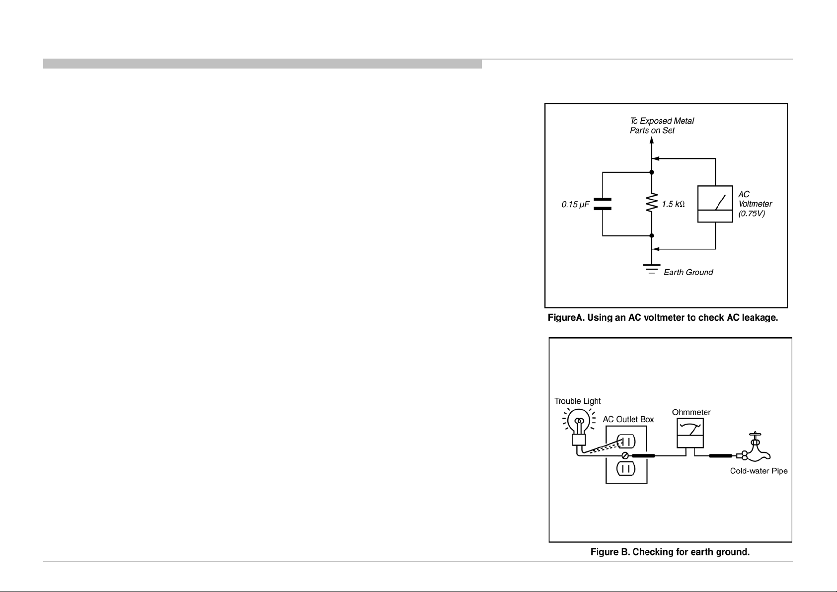
3. Measuring the voltage d rop across a resistor by means of a VOM or battery -operated AC voltmeter. The
“limit” indication is 0.75 V, so analog meters must have an accurate low voltage scale.
The Simpson’s 250 and Sanwa SH-63TRD are examples of passive VO Ms that are suita bl e. Nearly all
battery-operated dig ital multim eters that have a 2 VAC range are suitable (see Figure A).
How to Find a Good Earth Ground
A cold-water pipe is a guaranteed earth ground; the cover-plate retaining screw on most AC outlet boxes is also
at earth ground.
If the retaining screw is to be used as your earth ground, verify that it is at ground by measuring the resistance
between it and a cold-water pipe with an ohmmeter. The reading should be zero ohms.
If a cold-water pipe is not accessible, connect a 60- to 100-watt trouble- light (not a neon lamp) between the hot
side of the receptacle and the retaining screw. Try both slots, if necessary, to locate the hot side on the line; the
lamp should light at normal brilliance if the screw is at ground potential (see Figure B).
SAFETY CHECK-OUT
KD-55/65X9000A(CH)
7
Page 8
SELF DIAGNOSIS FUNCTION
The units in this manual c ontain a self-diagnostic function. If an error occ urs, the Smart Core Red LED will automatically b egin to flash.
The number of times the LED flashes translates to a probable source of the problem.
A definition of the Smart Core Red LED flash indicators is listed in the instruction manual for the user’s knowledge and reference.
If an error symptom cannot be reproduced, the remote commander can be used to review the failure occurrence data stored in memory to reveal past problems and how often these
problems occur.
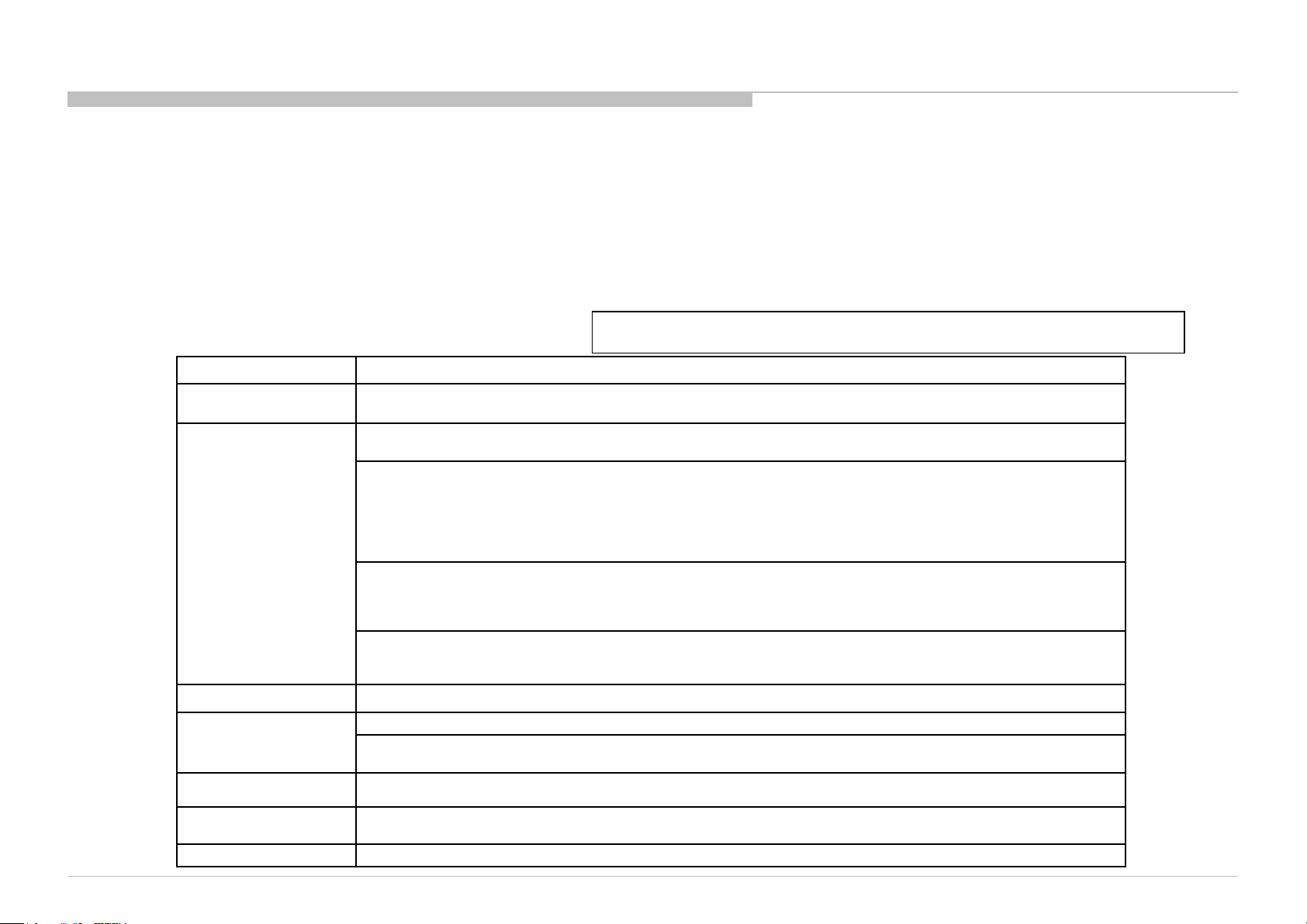
DIAGNOSTIC TEST INDICATORS
When an error occurs, the Smart Core Red LED will flash a set number of times to indicate the possible cause of the problem.
If there is more than one error, the LED will identify the first of the problem areas.
Result for all of the following diagnostic items are displayed on screen.
If the screen displays a “0”, no error has occurred .
RED LED blinking count Detection Items
2x
3x
4x <L/P> LED driver failure/LED voltage protection [LD_ERR]
5x
<G/B> Main 12V failure [MAIN_POWE]
* This failure is not saved.
<B> Main 5.0/3.3/1.8/1.0/ 1.1V failure [DC_ALERT]
* 5.0/1.0V failures are not saved.
<B/S> Audio amp. protection [AUD_PROT]
<B> HDMI equalizer/switch I2C NACK [HDMI_EQ] * There is Temp. sensor on the same I2C bus
<C> HDMI switch/equalizer I2C communication monitoring. [HDMI_EQCX]
<B> Tuner or demodulator I2C NACK [TU_DEMOD]
<B> AFE device I2C NACK [AFE_I2C]
<B> AFE device SPI NACK [AFE_SPI] * only for AEP,CH
<B> Scorpio VBO Tx Lock monitoring. [SC_OUT_ERR]
<B> VBO Lock monitoring between Ayu2 and Scorpio. [SC_ERR]
<B> Scorpio SPI Flash read error detection. [SC_ERR]
<B> Scorpio device I2C communication error detection. [SC_ERR]
<B> DDR-PHY DLL ready error detection for FRC. [FRCD_I2C]
<B> DRAM initial sequence done error detection for FRC. [FRCD_I2C]
<B> FRC device I2C communication error detection. [FRCD_I2C]
<P/T/G/B> Panel ID EEPROM I2C NACK (Also panel power failure is a suspect) [P_ID_ERR]
<T> TCON device I2C NACK [TCON_ERR]
<T> TCON device Initialization failure [TCON_ERR]
<G>: Power supply board, <B>: Main board, <T>: Tcon board, <L>: LED driver (LD) board
<P>: Panel module , <S>: Speaker, <A>: Power Adapter, <C>: CX board
KD-55/65X9000A(CH)
6x <G/T/P/B> Backlight converter OVP[BACKLITE]
7x
8x Software Error (Also the main board’s memory or CAM module is a suspect)
Over temperature protection [TEMP_ERR]
<B> Temp. sensor I2C NACK [TEMP_ERR] * There is HDMI Eq on the same I2C bus.
8
Page 9
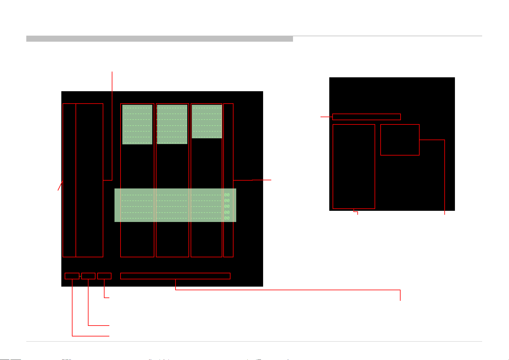
[SELF DIAGNOSTIC SCREEN DISPL AY]
SELF DIAGNOSIS FUNCTION
Smart Core
Red LED
blinking count
Error item name
SELF CHECK
002 MAIN_POWE ------------ ------------ ------------ 00
003 AFE_I2C ------------ ------------ ------------ 00
003 DC_ALERT ------------ ------------ ------------ 00
003 AUD_PROT ------------ ------------ ------------ 00
003 HDMI_EQ ------------ ------------ ------------ 00
003 TU_DEMOD ------------ ------------ ------------ 00
003 AFE_SPI ------------ ------------ ------------ 00
003 SC_OUTERR ------------ ------------ ------------ 00
003 SC_ERR ------------ ------------ ------------ 00
003 FRCD_I2C ------------ ------------ ------------ 00
003 HDMI_EQCX ------------ ------------ ------------ 00
004 VLED ------------ ------------ ------------ 00
004 LD_ERR ------------ ------------ ------------ 00
005 TCON_ERR 120823132523 ------------ ------------ 01
005 P_ID_ERR ------------ ------------ ------------ 00
005 PCON_ERR ------------ ------------ ------------ 00
005 TG_ERR ------------ ------------ ------------ 00
006 BACKLITE ------------ ------------ ------------ 00
007 TEMP_ERR ------------ ------------ ------------ 00
007 FAN_ERR ------------ ------------ ------------ 00
008 VPC_WDT ------------ ------------ ------------ 00
008 MEPS_WDT ------------ ------------ ------------ 00
008 HOST_WDT ------------ ------------ ------------ 00
008 STBY_WDT ------------ ------------ ------------ 00
008 AFE_WDT ------------ ------------ ------------ 00
010 EMIT_ERR ------------ ------------ ------------ 00
00081-00671-00088 00000000000000000570-00000000000000000132
Format of error timestamps
YYMMDDhhmmss (in UTC)
Example:
120823132523 -> Aug 23 2012 13:25:23 UTC
* Only when time is set, an error timestamp is saved.
*Following error is invalid in FSML.
FAN_ERR
EMIT_ERR
PCON_ERR
Error
timestamp
for last
recorded
error
Error
timestamp
for second
last
recorded
error
Error
timestamp
for 3rd last
recorded
error
Error count
MAC address
of Wi-Fi USB
dongle*1.
*1
1. When no Wi-Fi USB dongle is connected, NA is displayed.
2. If you insert/disconnect Wi-Fi USB Dongle during Self Diagnosis
- Alternatively, you can re-display Self D iagnosis D isplay t o update the
Model Name :
Serial Number :
Package Number : PKG0.651JPA
Device ID : B0:00:01:67:BB:33
Wired Mac : 3C:07:71:46:86:6D
Wireless Mac : N/A
USB dongle : N/A
<MAIN> <EXT>
DM0.651JPA WF:3.0.0.1023
WF0.430W00AA WF:--------
DF3.011W00AA FD:-.--YM1.010W00AA BT:1.2.14.940
M5.001C
(DM0.651JPA) <FS>
DD2.050W00AA EFR:03.00.00.14
PK2.050W00AA DNC:----------AM0.650JP DNI:---------- DNF:----MID:072DB8A1
PID:0F060040 SCF:20.01
PNL:T550QVD02.0 SYE:
Main CPU
information
External module
information
Display, press <1> -> <4> on remote commander to refresh Mac
address displayed on “USB dongle”.
information.
KD-55/65X9000A(CH)
Panel operation time by hour
Panel Operation Time is recorded every 30 min, but T otal Oper ation Time is recorded every 1 hr.
Therefore, the panel op. time might become lar ger t han the total op. time.
Boot count
Total operation time by hour
Count of writing to NAND device:
As vfat partition– As ext4 partition
9
Page 10
SELF DIAGNOSIS FUNCTION
SELF-DIAGNOSTIC SCREEN DISPLAY
For errors with symptoms such as “power sometimes shuts off” or “screen sometimes goes out” that cannot be confirmed, it is possible to bring up past occurrences of failure for
confirmation on the screen:
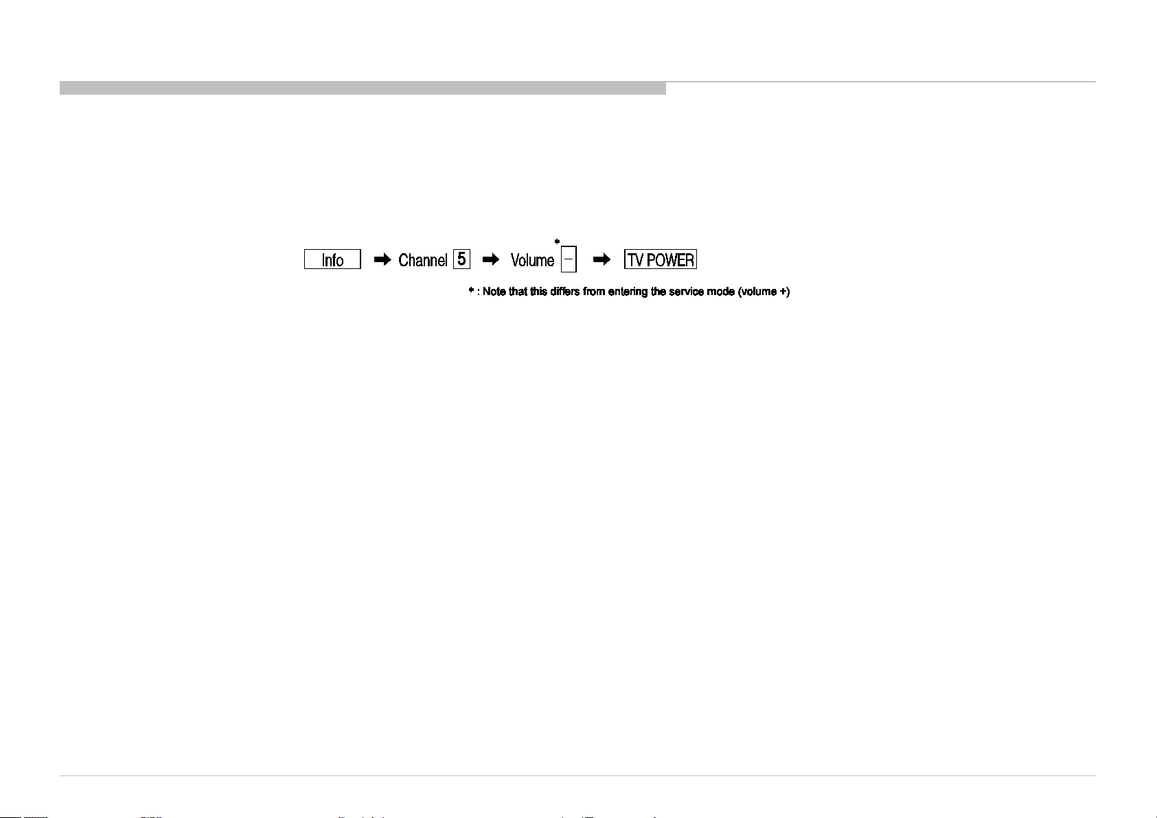
[To Bring Up Screen Test]
In standby mode, press buttons on the remote commander sequentially in rapid succession as shown below:
Since the diagnostic results displayed on the screen are not automatically cleared, always check the self-diagnostic screen.
After you have completed the repairs, clear the result display to “0”.
Clearing the Self Check Diagnostic List
1. Error history and Error count : Press the Channel 8 => Channel 0 .
2. Panel operation time : Press the Channel 7 => Channel 0 .
Exiting the Self-diagnostic screen
To exit the Self Diagnostic screen, turn off the power to the TV by pressing the POWER button on the remote or the POWER button on the TV.
KD-55/65X9000A(CH)
10
Page 11

SEC 1. DISASSEMBLY
• There are clutch in the yellow frame[ ]. Therefore please be careful in the case of the disassembly or assembly of parts.
KD-55/65X9000A(CH)
11
Page 12
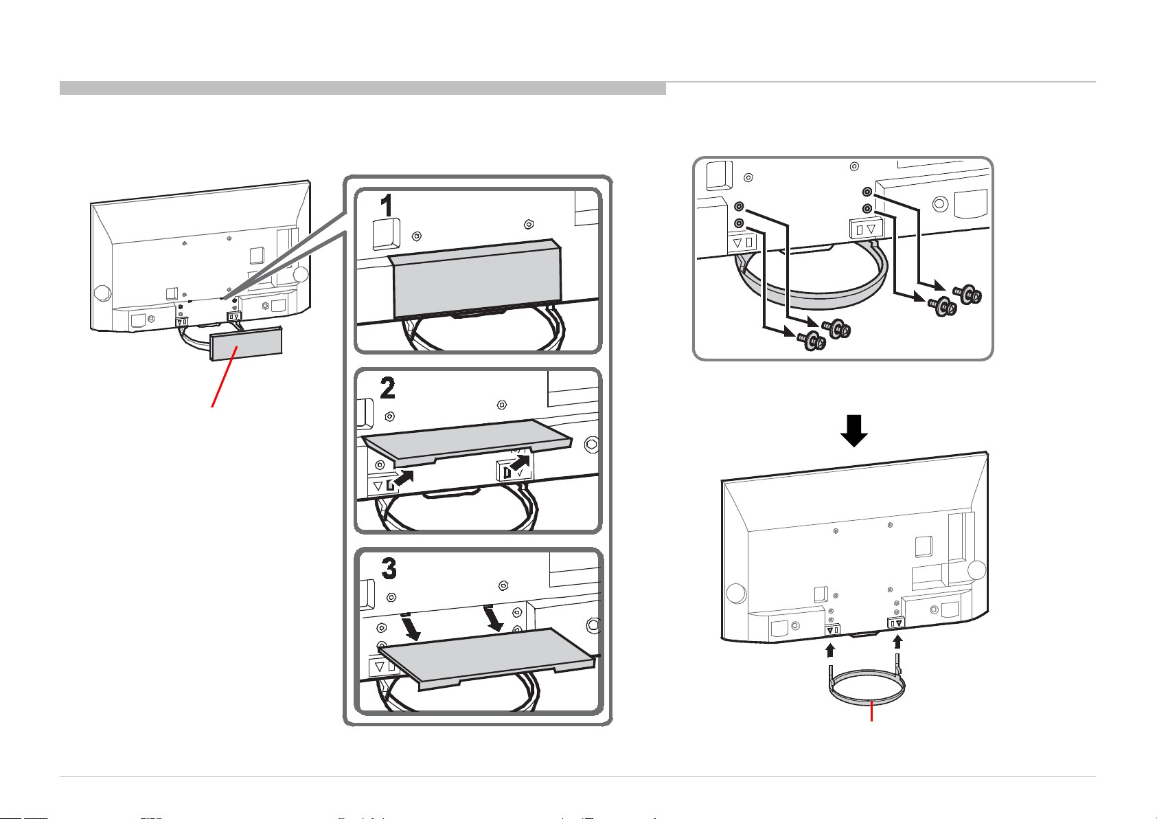
1-1. KD-55X9000A
COVER, UNDER (L CCT) AND STAND BLOCK
COVER, UNDER (L CCT)
Part Number: 4-454-665-01
DISASSEMBLY
4 Screws (SCREW, +PSW M5X12) P/N: 2-580-607-01
KD-55/65X9000A(CH)
STAND BLOCK
12
Page 13
1-1. KD-55X9000A
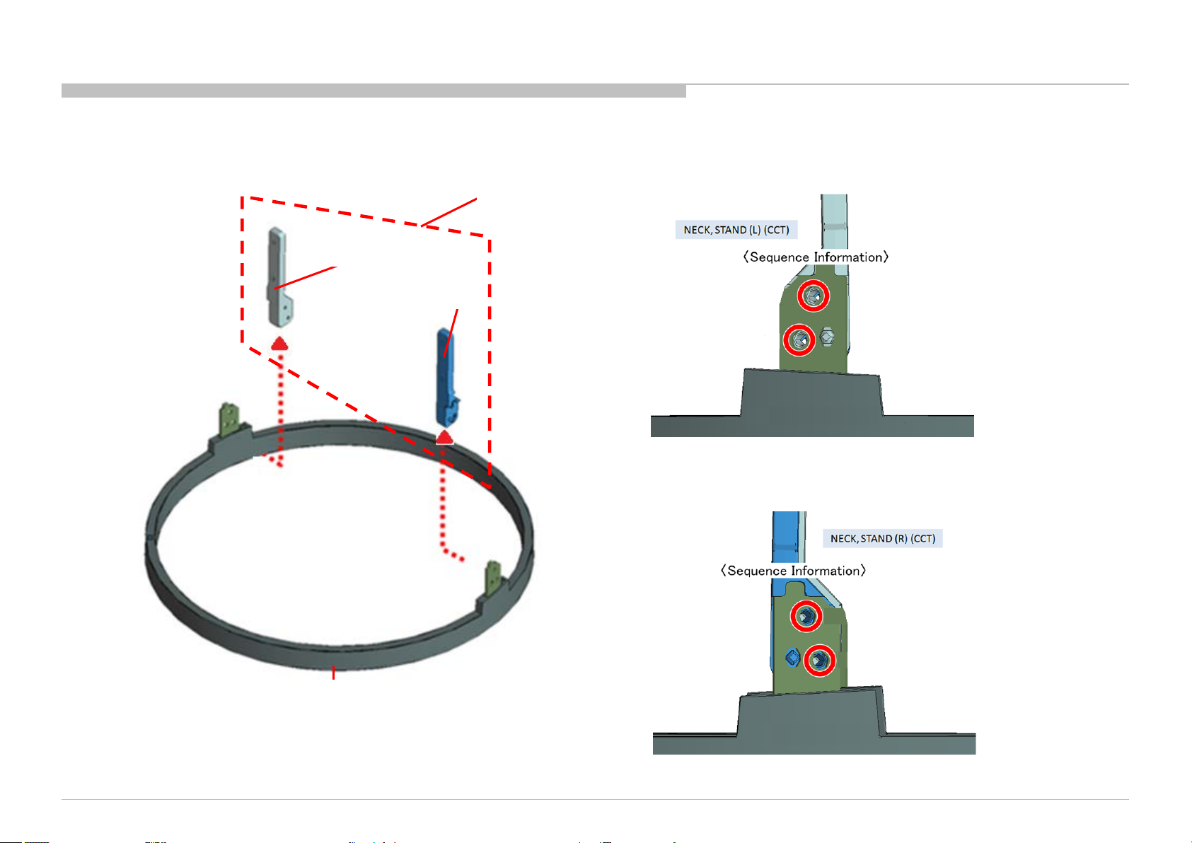
NECK, STAND (CCT) A AND STAND (CCT) A
NECK, STAND (L) (CCT)
NECK, STAND (R) (CCT)
DISASSEMBLY
NECK, STAND (CCT) A
Part Number: 4-462-872-01
2 Screws (SCREW, +PSW M5X12) P/N: 2-580-607-01
KD-55/65X9000A(CH)
STAND (CCT) A
Part Number: 4-454-672-01
2 Screws (SCREW, +PSW M5X12) P/N: 2-580-607-01
13
Page 14
1-1. KD-55X9000A
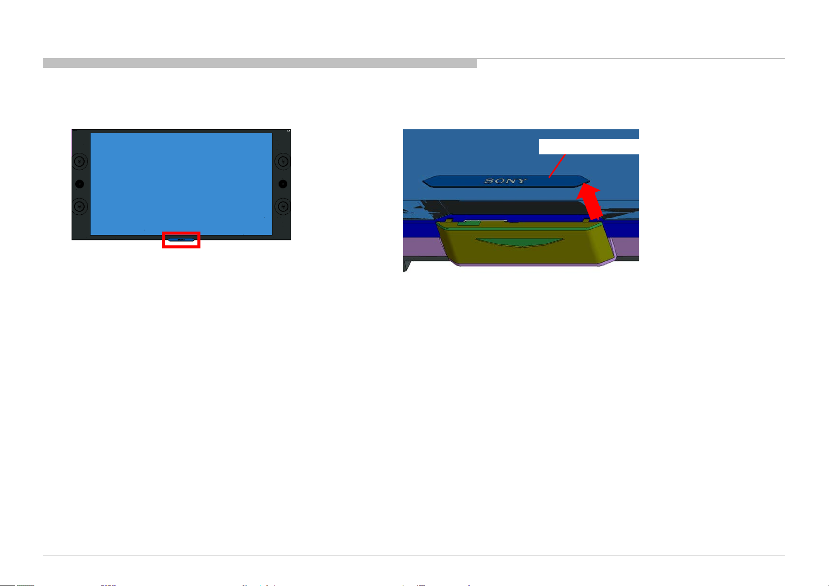
PANEL ORNAMENT, SC (CCT ) A
DISASSEMBLY
PANEL ORNAMENT, SC (CCT) A
KD-55/65X9000A(CH)
14
Page 15
1-1. KD-55X9000A
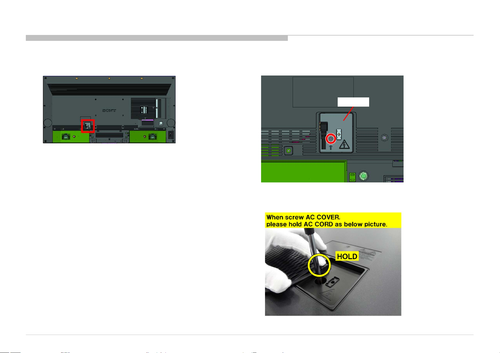
AC COVER
DISASSEMBLY
AC COVER
1 Screw (SCREW, +PSW M3X6 W12) P/N: 4-256-393-01
KD-55/65X9000A(CH)
15
Page 16
1-1. KD-55X9000A
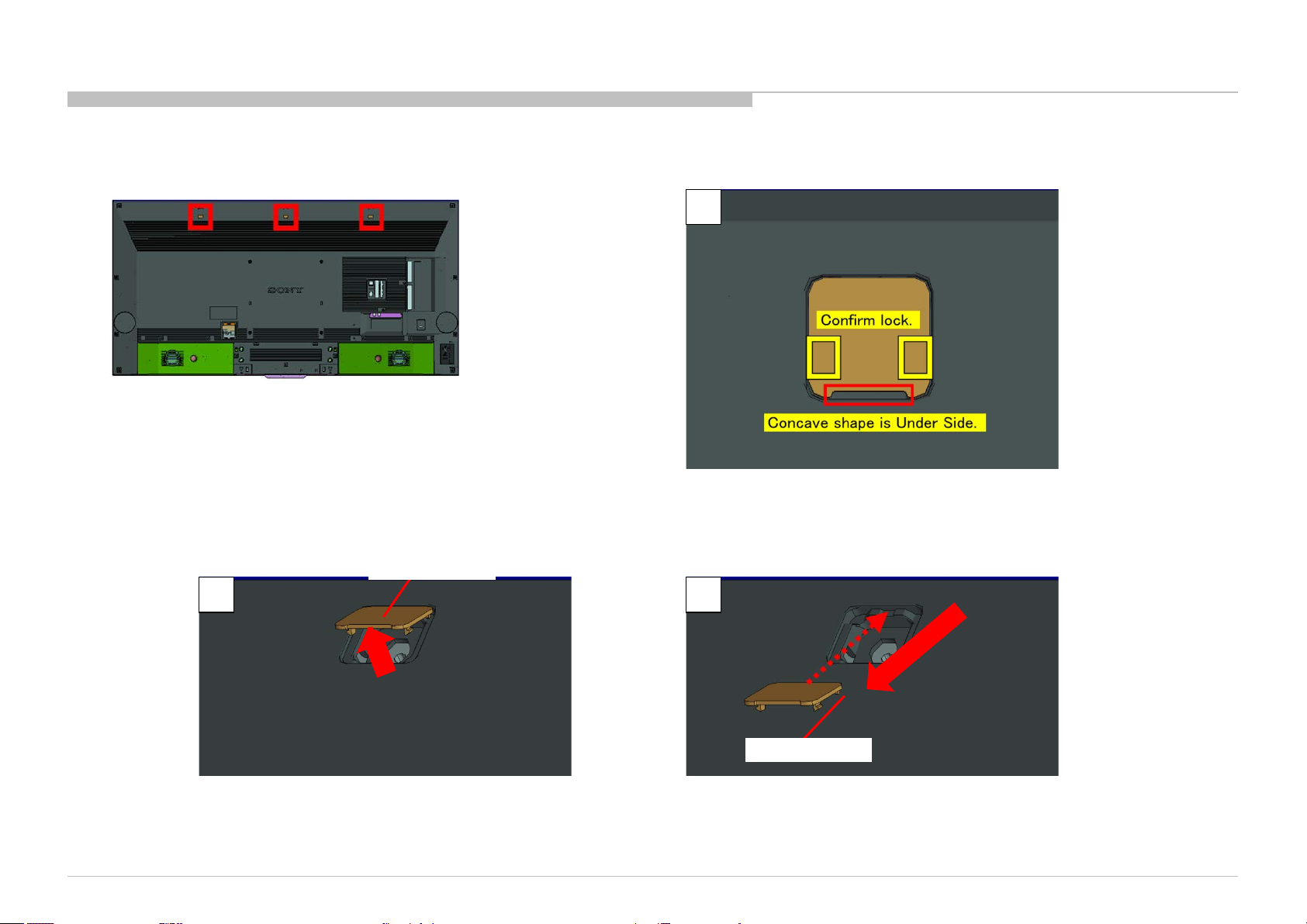
CCT CAP SCREW
DISASSEMBLY
1
KD-55/65X9000A(CH)
CCT CAP SCREW
2 3
CCT CAP SCREW
16
Page 17
1-1. KD-55X9000A
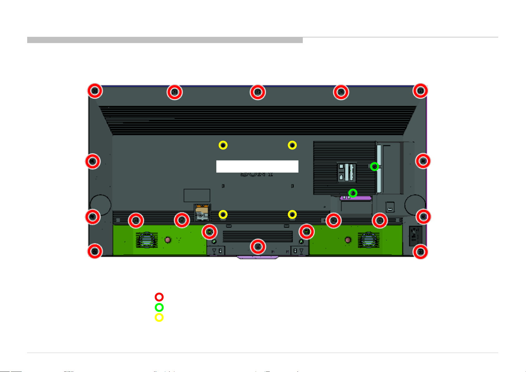
REAR COVER (L CCT) A
DISASSEMBLY
REAR COVER (L CCT) A
KD-55/65X9000A(CH)
18 Screws (SCREW, +PSW M3X 6 STEP) P/N: 4-457-815-02
2 Screws (SCREW +BVTP 3X10 TYPE2 IT-3) P/N: 7-685-647-79
4 Screws (SCREW, ORNAMENTAL M6X12) P/N: 4-268-126-02
17
Page 18
1-1. KD-55X9000A
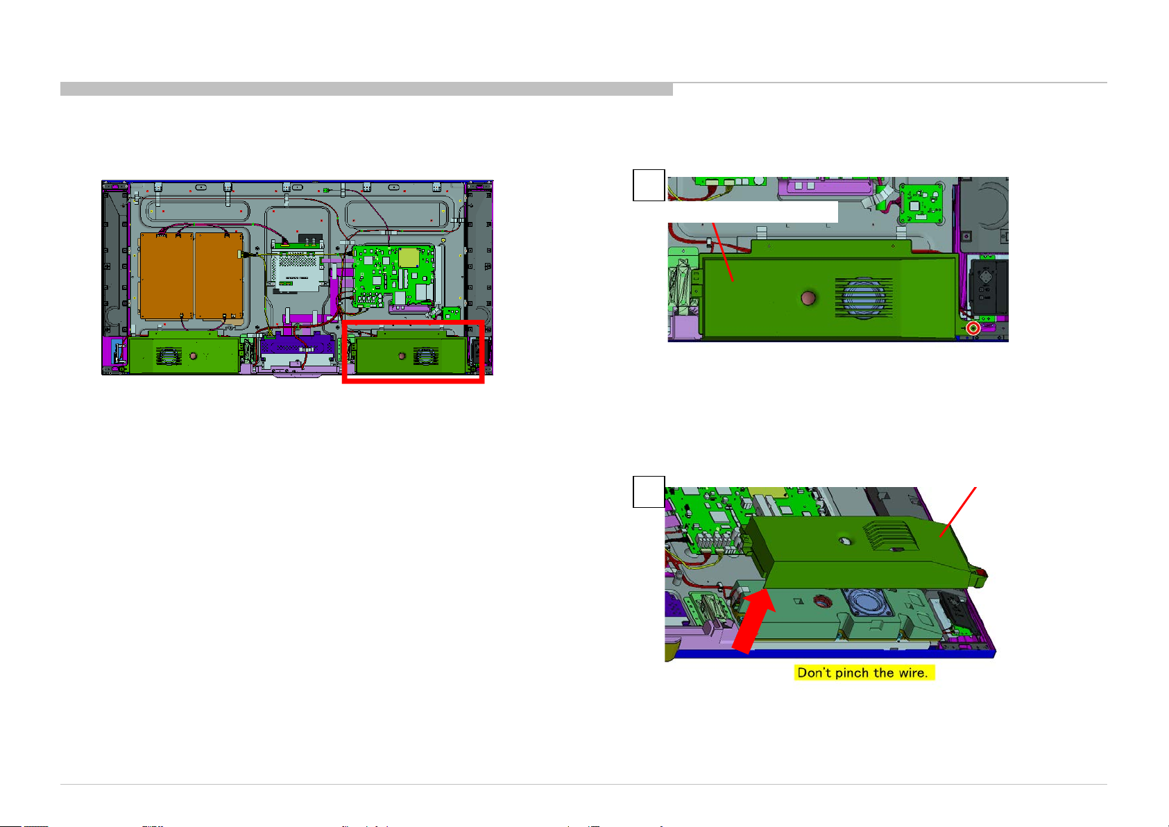
COVER, WOOFER (L) (CCT)
DISASSEMBLY
1
COVER, WOOFER (L) (CCT)
1 Screw (SCREW, +PSW M3X6 W12) P/N: 4-256-393-01
COVER, WOOFER (L) (CCT)
2
KD-55/65X9000A(CH)
18
Page 19
1-1. KD-55X9000A
COVER, WOOFER (R) (CCT)
DISASSEMBLY
1
COVER, WOOFER (R) (CCT)
1 Screw (SCREW, +PSW M3X6 W12) P/N: 4-256-393-01
COVER, WOOFER (R) (CCT)
KD-55/65X9000A(CH)
2
19
Page 20
1-1. KD-55X9000A
BRACKET, NECK (CCT)
DISASSEMBLY
1
6 Screws (SCREW, +PSW M4X10) P/N: 4-159-298-01
2
KD-55/65X9000A(CH)
BRACKET, NECK (CCT)
20
Page 21
1-1. KD-55X9000A
BRACKET, UNDER (CCT)
DISASSEMBLY
1
1 Screw (SCREW +BVTP 3X10 TYPE2 IT-3) P/N: 7-685-647-79
KD-55/65X9000A(CH)
2
BRACKET, UNDER (CCT)
21
Page 22
1-1. KD-55X9000A
CONNECTOR ASSY AND FFC
CONNECTOR ASSY 28P
Part Number: 1-910-107-75
FLEXIBLE FLAT CABLE 20P
Part Number: 1-910-107-78
DISASSEMBLY
FLEXIBLE FLAT CABLE 41P (FSL)
Part Number: 1-846-699-11
KD-55/65X9000A(CH)
HARNESS ASSY (MAIN)
Part Number: 1-910-107-76
LEAD WIRE WITH CONNECTOR 51P
Part Number: 1-846-697-11
CONNECTOR ASSY 3P
Part Number: 1-910-107-83
FLEXIBLE FLAT CABLE 51P (FSL)
Part Number: 1-846-698-11
22
Page 23
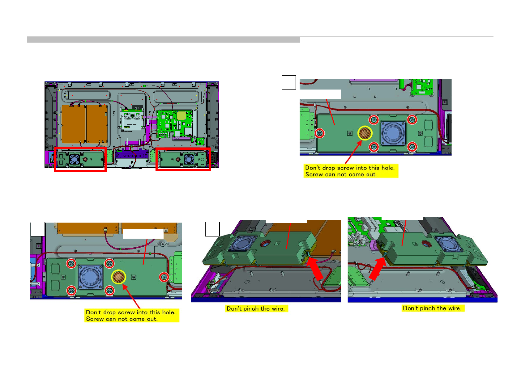
1-1. KD-55X9000A
SP BOX ASSY
DISASSEMBLY
1
SP BOX ASSY
5 Screws (SCREW, +PSW M3X6 W12) P/N: 4-256-393-01
2 3
5 Screws (SCREW, +PSW M3X6 W12) P/N: 4-256-393-01
KD-55/65X9000A(CH)
SP BOX ASSY
SP BOX ASSY
SP BOX ASSY
23
Page 24
1-1. KD-55X9000A
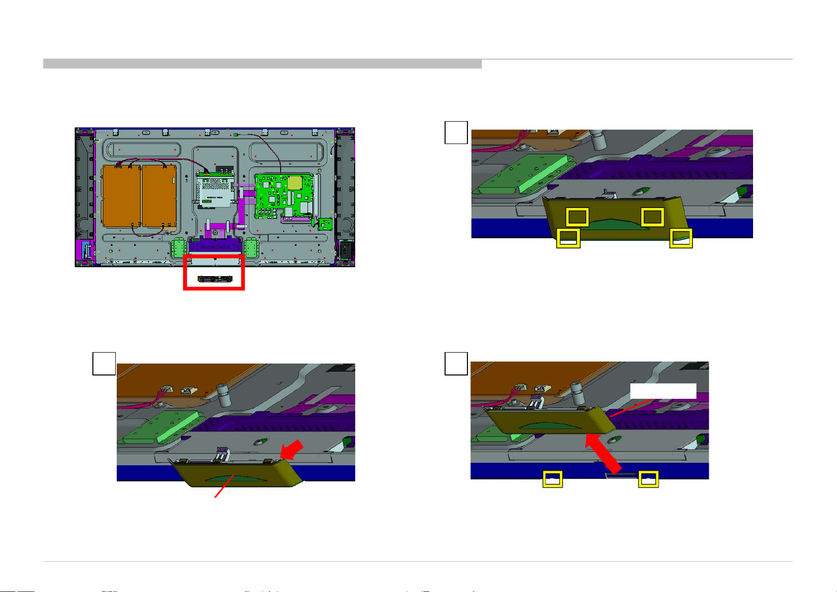
SMART CORE
DISASSEMBLY
1
KD-55/65X9000A(CH)
3 2
SMART CORE
SMART CORE
24
Page 25
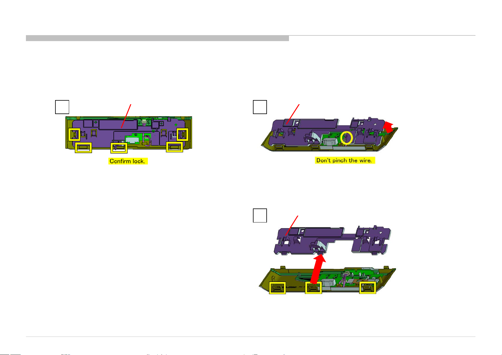
1-1. KD-55X9000A
LID,SC(CCT) A
1 2
DISASSEMBLY
LID,SC(CCT) A LID,SC(CCT) A
KD-55/65X9000A(CH)
3
LID,SC(CCT) A
25
Page 26
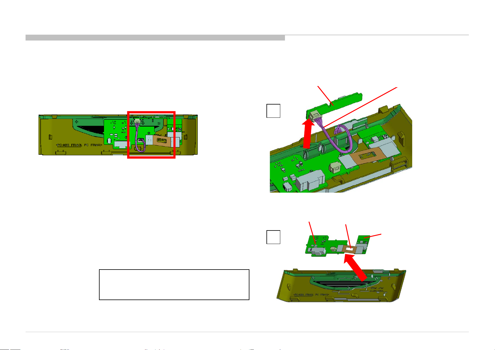
1-1. KD-55X9000A
HIF BOARD, HSF-LM BOARD, BLUETOOTH MODULE AND FPC-BT
DISASSEMBLY
1
HSF-LM BOARD
2
HIF BOARD
CONNECTOR ASSY 5P
Part Number: 1-910-107-74
FPC-BT
BLUETOOTH MODULE
KD-55/65X9000A(CH)
Note:
FPC-BT is not reusable.
Please replace FPC-BT to new one if FPC-BT is removed
from HSF-LM BOARD or BLUETOOTH MODULE.
26
Page 27
1-1. KD-55X9000A
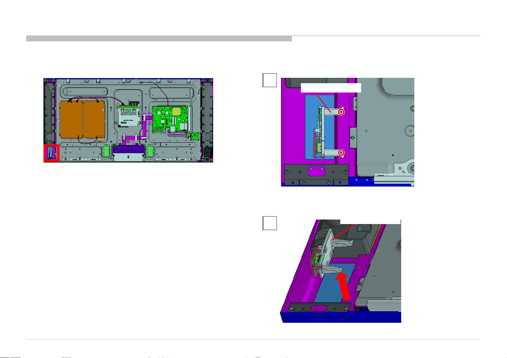
WLAN MODULE ASS Y
DISASSEMBLY
1
WLAN MODULE ASSY
2 Screws (SCREW (+PSW) (M3X6)) P/N: 2-990-421-41
KD-55/65X9000A(CH)
2
WLAN MODULE ASSY
27
Page 28
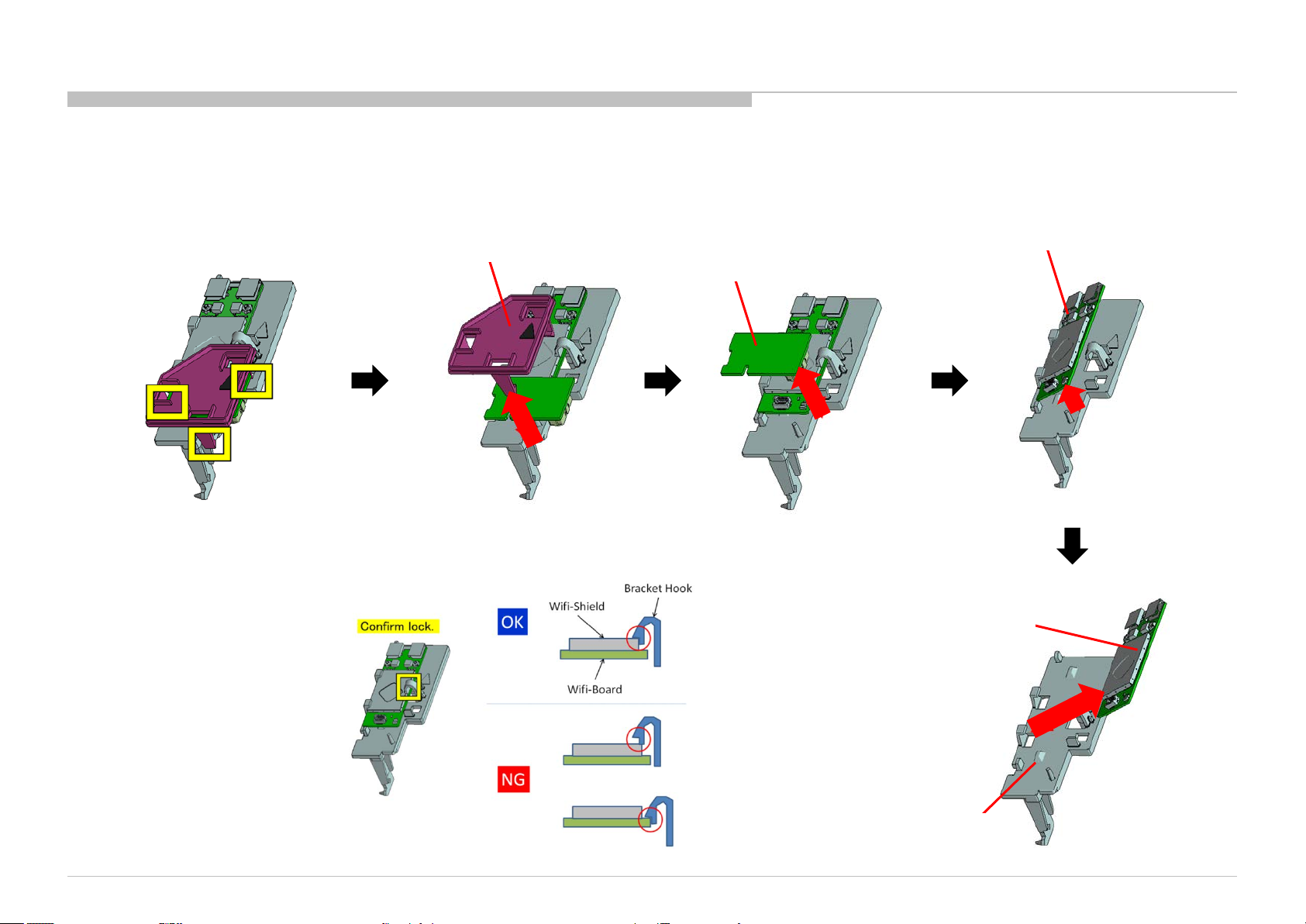
1-1. KD-55X9000A
COVER,MODULE(CCT) A, HW BOARD, WLAN MODULE AND BRACKET, MODULE (CCT)
DISASSEMBLY
COVER,MODULE(CCT) A
WLAN MODULE
HW BOARD
WLAN MODULE
KD-55/65X9000A(CH)
BRACKET, MODULE (CCT)
28
Page 29
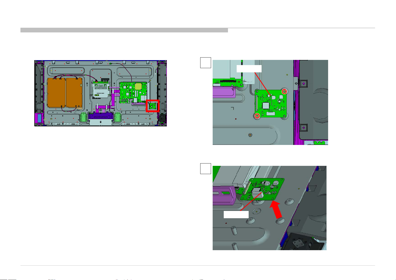
1-1. KD-55X9000A
CX BOARD
DISASSEMBLY
1
CX BOARD
2 Screws (SCREW (+PSW) (M3X6)) P/N: 2-990-421-41
KD-55/65X9000A(CH)
2
CX BOARD
29
Page 30
1-1. KD-55X9000A
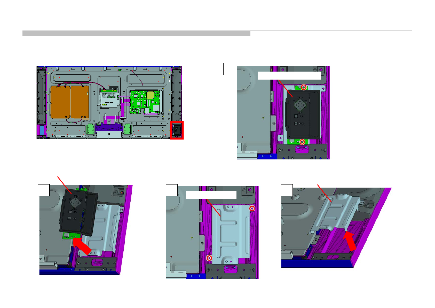
SWITCH UNIT (HUS -F WW) AND BRACKET, HUS(CCT)
SWITCH UNIT (HUS-F WW)
DISASSEMBLY
1
SWITCH UNIT (HUS-F WW)
2 Screws (SCREW (+PSW) (M3X6)) P/N: 2-990-421-41
BRACKET, HUS(CCT)
2 3 4
KD-55/65X9000A(CH)
BRACKET, HUS(CCT)
2 Screws (SCREW (+PSW) (M3X6)) P/N: 2-990-421-41
30
Page 31

1-1. KD-55X9000A
BRACKET, UNDER (MOLD) AND BRACKET SIDE (MOLD CCT)
DISASSEMBLY
KD-55/65X9000A(CH)
BRACKET SIDE (MOLD CCT)
BRACKET, UNDER (MOLD)
31
Page 32

1-1. KD-55X9000A
BAF BOARD
DISASSEMBLY
1
13 Screws (SCREW (+PSW) (M3X6)) P/N: 2-990-421-41
BAF BOARD
2
KD-55/65X9000A(CH)
BAF BOARD
32
Page 33

1-1. KD-55X9000A
SHEET, THERMAL (BAF) AND GASKET(BAF)
DISASSEMBLY
KD-55/65X9000A(CH)
SHEET, THERMAL (BAF)
33
Page 34

1-1. KD-55X9000A
TS BOARD
DISASSEMBLY
1
TS BOARD
1 Screw (SCREW (+PSW) (M3X6)) P/N: 2-990-421-41
TS BOARD
KD-55/65X9000A(CH)
2
34
Page 35

1-1. KD-55X9000A
CONNECTOR ASSY AND HERNESS ASSY
DISASSEMBLY
CONNECTOR ASSY, 3P
Part Number: 1-846-714-11
HARNESS ASSY (G-LD)
Part Number: 1-910-107-77
KD-55/65X9000A(CH)
35
Page 36

1-1. KD-55X9000A
G7 BOARD AND G6 BOARD
DISASSEMBLY
1
2
G7 BOARD
5 Screws (SCREW (+PSW) (M3X6)) P/N: 2-990-421-41
G6 BOARD
G6 BOARD
G7 BOARD
KD-55/65X9000A(CH)
G6 BOARD
5 Screws (SCREW (+PSW) (M3X6)) P/N: 2-990-421-41
36
Page 37

1-1. KD-55X9000A
SHEET, INSULATION (CCT L)
DISASSEMBLY
1
SHEET, INSULATION (CCT L)
2
KD-55/65X9000A(CH)
SHEET, INSULATION (CCT L)
37
Page 38

1-1. KD-55X9000A
TAPE 95
DISASSEMBLY
KD-55/65X9000A(CH)
38
Page 39

1-1. KD-55X9000A
COVER, SP (L) (CCT) ASSY
DISASSEMBLY
1
COVER, SP (L) (CCT) ASSY
12 Screws (SCREW +PSW 3X10) P/N: 7-682-949-09
2 Screws (SPACER(SP-RC), HEX) P/N: 4-457-814-02
COVER, SP (L) (CCT) ASSY
KD-55/65X9000A(CH)
2 3
COVER, SP (L) (CCT) ASSY
39
Page 40

1-1. KD-55X9000A
COVER, SP (R) (CCT) ASSY
DISASSEMBLY
1
12 Screws (SCREW +PSW 3X10) P/N: 7-682-949-09
2 Screws (SPACER(SP-RC), HEX) P/N: 4-457-814-02
3 2
COVER, SP (R) (CCT) ASSY
COVER, SP (R) (CCT) ASSY
COVER, SP (R) (CCT) ASSY
KD-55/65X9000A(CH)
40
Page 41

1-1. KD-55X9000A
LOUD SPEAKER (80MM)
DISASSEMBLY
LOUD SPEAKER (80MM)
KD-55/65X9000A(CH)
41
Page 42

1-1. KD-55X9000A
LOUD SPEAKER (18MM)
1 2
DISASSEMBLY
KD-55/65X9000A(CH)
LOUD SPEAKER (18MM)
LOUD SPEAKER (18MM)
2 Screws (SCREW +BVTP 3X10 TYPE2 IT-3) P/N: 7-685-647-79
42
Page 43

1-1. KD-55X9000A
BRACKET,TW (CCT)
DISASSEMBLY
1 2
2 Screws (SCREW (+PSW) (M3X6)) P/N: 2-990-421-41
KD-55/65X9000A(CH)
BRACKET,TW (CCT)
BRACKET,TW (CCT)
43
Page 44

1-1. KD-55X9000A
MOUNTED PWB (NETWORK)
DISASSEMBLY
1
MOUNTED PWB (NETWORK)
2 Screws (SCREW (+PSW) (M3X6)) P/N: 2-990-421-41
MOUNTED PWB (NETWORK)
2 3
KD-55/65X9000A(CH)
MOUNTED PWB (NETWORK)
44
Page 45

1-1. KD-55X9000A
LOUD SPEAKER (80MM)
DISASSEMBLY
LOUD SPEAKER (80MM)
KD-55/65X9000A(CH)
45
Page 46

1-1. KD-55X9000A
LOUD SPEAKER (18MM)
1 2
DISASSEMBLY
LOUD SPEAKER (18MM)
2 Screws (SCREW +BVTP 3X10 TYPE2 IT-3) P/N: 7-685-647-79
KD-55/65X9000A(CH)
LOUD SPEAKER (18MM)
46
Page 47

1-1. KD-55X9000A
BRACKET,TW (CCT)
DISASSEMBLY
1 2
KD-55/65X9000A(CH)
BRACKET,TW (CCT)
BRACKET,TW (CCT)
2 Screws (SCREW (+PSW) (M3X6)) P/N: 2-990-421-41
47
Page 48

1-1. KD-55X9000A
MOUNTED PWB (NETWORK)
DISASSEMBLY
1
MOUNTED PWB (NETWORK)
2 Screws (SCREW (+PSW) (M3X6)) P/N: 2-990-421-41
MOUNTED PWB (NETWORK)
2 3
KD-55/65X9000A(CH)
MOUNTED PWB (NETWORK)
48
Page 49

1-1. KD-55X9000A
LOUD SPEAKER( P ASS IVE RADI AT O R )
LOUD SPEAKER(PASSIVE RADIATOR)
DISASSEMBLY
KD-55/65X9000A(CH)
49
Page 50

1-1. KD-55X9000A
BRACKET,SP (CCT)
2 3
DISASSEMBLY
1
BRACKET,SP (CCT)
BRACKET,SP (CCT)
BRACKET,SP (CCT)
KD-55/65X9000A(CH)
50
Page 51

1-1. KD-55X9000A
ORNAMENT,SP (CCT)
DISASSEMBLY
KD-55/65X9000A(CH)
1 2
ORNAMENT,SP (CCT)
ORNAMENT,SP (CCT)
51
Page 52

1-1. KD-55X9000A
ORNAMENT,SP (CCT)
DISASSEMBLY
ORNAMENT,SP (CCT)
KD-55/65X9000A(CH)
1 2
ORNAMENT,SP (CCT)
52
Page 53

1-1. KD-55X9000A
LCD PANEL
DISASSEMBLY
LCD PANEL
6 Screws (SCREW, +PSW M4X10) P/N: 4-159-298-01
KD-55/65X9000A(CH)
53
Page 54

1-1. KD-55X9000A
WIRE DRESSING-1
2
3
DISASSEMBLY
1 2
1
3
KD-55/65X9000A(CH)
54
Page 55

1-1. KD-55X9000A
WIRE DRESSING-2
DISASSEMBLY
KD-55/65X9000A(CH)
55
Page 56

1-1. KD-55X9000A
WIRE DRESSING-3
BAF Board
DISASSEMBLY
CX Board
BAF Board
KD-55/65X9000A(CH)
CX Board
56
Page 57

1-2. KD-65X9000A
COVER, UNDER (M CCT) AND STAND BLOCK
COVER, UNDER (M CCT)
Part Number: 4-454-666-01
DISASSEMBLY
KD-55/65X9000A(CH)
STAND BLOCK
57
Page 58

1-2. KD-65X9000A
NECK, STAND (CCT) A AND STAND (CCT) A
NECK, STAND (L) (CCT)
NECK, STAND (R) (CCT)
DISASSEMBLY
NECK, STAND (CCT) A
Part Number: 4-462-872-01
2 Screws (SCREW, +PSW M5X12) P/N: 2-580-607-01
KD-55/65X9000A(CH)
STAND (CCT) A
Part Number: 4-454-672-01
2 Screws (SCREW, +PSW M5X12) P/N: 2-580-607-01
58
Page 59

1-2. KD-65X9000A
PANEL ORNAMENT, SC (CCT ) A
DISASSEMBLY
PANEL ORNAMENT, SC (CCT) A
KD-55/65X9000A(CH)
59
Page 60

1-2. KD-65X9000A
AC COVER
DISASSEMBLY
AC COVER
1 Screw (SCREW, +PSW M3X6 W12) P/N: 4-256-393-01
KD-55/65X9000A(CH)
60
Page 61

1-2. KD-65X9000A
CCT CAP SCREW
DISASSEMBLY
1
KD-55/65X9000A(CH)
3 2
CCT CAP SCREW
CCT CAP SCREW
61
Page 62

1-2. KD-65X9000A
REAR COVER (M CCT) A
DISASSEMBLY
REAR COVER (M CCT) A
KD-55/65X9000A(CH)
18 Screws (SCREW, +PSW M3X 6 STEP) P/N: 4-457-815-02
2 Screws (SCREW +BVTP 3X10 TYPE2 IT-3) P/N: 7-685-647-79
4 Screws (SCREW, ORNAMENTAL M6X12) P/N: 4-268-126-02
62
Page 63

1-2. KD-65X9000A
COVER, WOOFER (L) (CCT)
DISASSEMBLY
1
COVER, WOOFER (L) (CCT)
1 Screw (SCREW, +PSW M3X6 W12) P/N: 4-256-393-01
KD-55/65X9000A(CH)
2
COVER, WOOFER (L) (CCT)
63
Page 64

1-2. KD-65X9000A
COVER, WOOFER (R) (CCT)
DISASSEMBLY
1
COVER, WOOFER (R) (CCT)
1 Screw (SCREW, +PSW M3X6 W12) P/N: 4-256-393-01
KD-55/65X9000A(CH)
2
COVER, WOOFER (R) (CCT)
64
Page 65

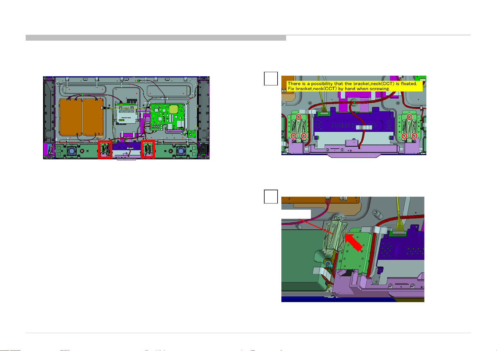
1-2. KD-65X9000A
BRACKET, NECK (CCT)
DISASSEMBLY
1
6 Screws (SCREW, +PSW M4X10) P/N: 4-159-298-01
KD-55/65X9000A(CH)
2
BRACKET, NECK (CCT)
65
Page 66

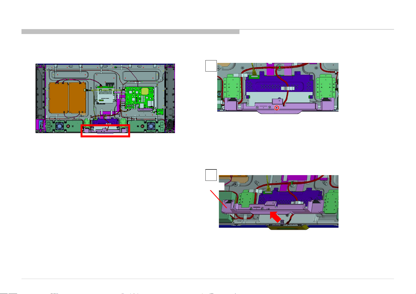
1-2. KD-65X9000A
BRACKET, UNDER (CCT)
DISASSEMBLY
1
1 Screw (SCREW +BVTP 3X10 TYPE2 IT-3) P/N: 7-685-647-79
KD-55/65X9000A(CH)
2
BRACKET, UNDER (CCT)
66
Page 67

1-2. KD-65X9000A
CONNECTOR ASSY AND FFC
CONNECTOR ASSY 28P
Part Number: 1-910-107-79
HARNESS ASSY (MAIN)
Part Number: 1-910-107-80
FLEXIBLE FLAT CABLE 20P
Part Number: 1-910-107-82
LEAD WIRE WITH CONNECTOR 51P
Part Number: 1-846-697-11
DISASSEMBLY
FLEXIBLE FLAT CABLE 41P (FSM)
Part Number: 1-846-701-11
FLEXIBLE FLAT CABLE 51P (FSM)
Part Number: 1-846-700-11
KD-55/65X9000A(CH)
CONNECTOR ASSY 3P
Part Number: 1-910-107-84
67
Page 68

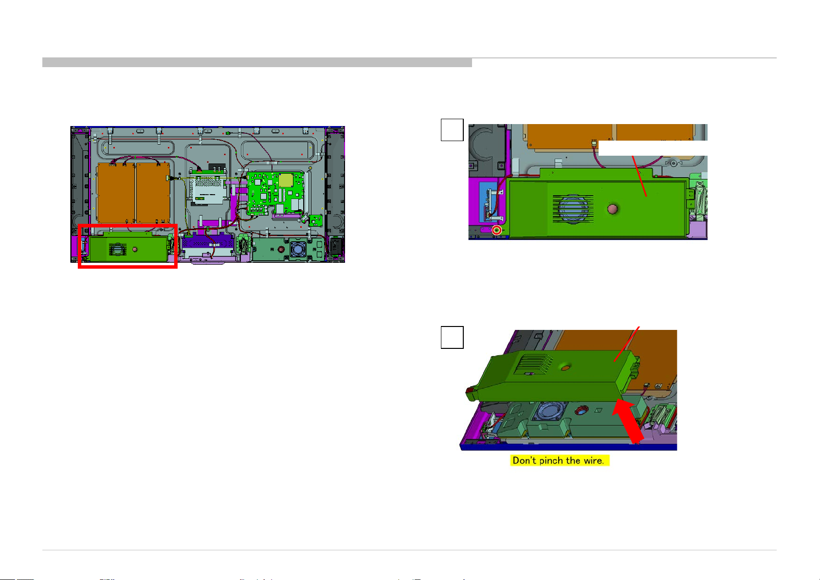
1-2. KD-65X9000A
SP BOX ASSY
DISASSEMBLY
1
SP BOX ASSY
5 Screws (SCREW, +PSW M3X6 W12) P/N: 4-256-393-01
2 3
5 Screws (SCREW, +PSW M3X6 W12) P/N: 4-256-393-01
KD-55/65X9000A(CH)
SP BOX ASSY
SP BOX ASSY
SP BOX ASSY
68
Page 69

1-2. KD-65X9000A
SMART CORE
DISASSEMBLY
1
KD-55/65X9000A(CH)
3 2
SMART CORE
SMART CORE
69
Page 70

1-2. KD-65X9000A
LID,SC(CCT) A
1 2
DISASSEMBLY
LID,SC(CCT) A LID,SC(CCT) A
KD-55/65X9000A(CH)
LID,SC(CCT) A
3
70
Page 71

1-2. KD-65X9000A
HIF BOARD, HSF-LM BOARD, BLUETOOTH MODULE AND FPC-BT
DISASSEMBLY
1
2
HSF-LM BOARD
HIF BOARD
CONNECTOR ASSY 5P
Part Number: 1-910-107-74
FPC-BT
BLUETOOTH MODULE
KD-55/65X9000A(CH)
Note:
FPC-BT is not reusable.
Please replace FPC-BT to new one if FPC-BT is removed
from HSF-LM BOARD or BLUETOOTH MODULE.
71
Page 72

1-2. KD-65X9000A
WLAN MODULE ASS Y
DISASSEMBLY
1
WLAN MODULE ASSY
2 Screws (SCREW (+PSW) (M3X6)) P/N: 2-990-421-41
KD-55/65X9000A(CH)
WLAN MODULE ASSY
2
72
Page 73

1-2. KD-65X9000A
COVER,MODULE(CCT) A, HW BOARD, WLAN MODULE AND BRACKET, MODULE (CCT)
DISASSEMBLY
COVER,MODULE(CCT) A
WLAN MODULE
HW BOARD
WLAN MODULE
KD-55/65X9000A(CH)
BRACKET, MODULE (CCT)
73
Page 74

1-2. KD-65X9000A
CX BOARD
DISASSEMBLY
1
CX BOARD
2 Screws (SCREW (+PSW) (M3X6)) P/N: 2-990-421-41
KD-55/65X9000A(CH)
2
CX BOARD
74
Page 75

1-2. KD-65X9000A
SWITCH UNIT (HUS -F WW) AND BRACKET, HUS(CCT)
DISASSEMBLY
1
SWITCH UNIT (HUS-F WW)
2 3 4
BRACKET, HUS(CCT)
SWITCH UNIT (HUS-F WW)
2 Screws (SCREW (+PSW) (M3X6)) P/N: 2-990-421-41
BRACKET, HUS(CCT)
KD-55/65X9000A(CH)
2 Screws (SCREW (+PSW) (M3X6)) P/N: 2-990-421-41
75
Page 76

1-2. KD-65X9000A
BRACKET, UNDER (MOLD) AND BRACKET SIDE (MOLD CCT)
DISASSEMBLY
KD-55/65X9000A(CH)
BRACKET SIDE (MOLD CCT)
BRACKET, UNDER (MOLD)
76
Page 77

1-2. KD-65X9000A
DISASSEMBLY
BAF BOARD
BAF BOARD
1
13 Screws (SCREW (+PSW) (M3X6)) P/N: 2-990-421-41
2
KD-55/65X9000A(CH)
BAF BOARD
77
Page 78

1-2. KD-65X9000A
SHEET, THERMAL (BAF) AND GASKET(BAF)
DISASSEMBLY
KD-55/65X9000A(CH)
SHEET, THERMAL (BAF)
78
Page 79

1-2. KD-65X9000A
TS BOARD
1 1
DISASSEMBLY
TS BOARD
1 Screw (SCREW (+PSW) (M3X6)) P/N: 2-990-421-41
KD-55/65X9000A(CH)
TS BOARD
2
79
Page 80

1-2. KD-65X9000A
CONNECTOR ASSY AND HERNESS ASSY
DISASSEMBLY
CONNECTOR ASSY, 3P
Part Number: 1-846-714-11
HARNESS ASSY (G-LD)
Part Number: 1-910-107-81
KD-55/65X9000A(CH)
80
Page 81

1-2. KD-65X9000A
G8 BOARD AND G6 BOARD
DISASSEMBLY
1
2
G8 BOARD
5 Screws (SCREW (+PSW) (M3X6)) P/N: 2-990-421-41
G6 BOARD
G6 BOARD
G8 BOARD
KD-55/65X9000A(CH)
G6 BOARD
5 Screws (SCREW (+PSW) (M3X6)) P/N: 2-990-421-41
81
Page 82

1-2. KD-65X9000A
SHEET, INSULATION (CCT M)
DISASSEMBLY
1
SHEET, INSULATION (CCT M)
KD-55/65X9000A(CH)
2
SHEET, INSULATION (CCT M)
82
Page 83

1-2. KD-65X9000A
TAPE 95
DISASSEMBLY
KD-55/65X9000A(CH)
83
Page 84

1-2. KD-65X9000A
COVER, SP (L) (CCT) ASSY
DISASSEMBLY
1
COVER, SP (L) (CCT) ASSY
12 Screws (SCREW +PSW 3X10) P/N: 7-682-949-09
2 Screws (SPACER(SP-RC), HEX) P/N: 4-457-814-02
COVER, SP (L) (CCT) ASSY
KD-55/65X9000A(CH)
3 2
COVER, SP (L) (CCT) ASSY
84
Page 85

1-2. KD-65X9000A
COVER, SP (R) (CCT) ASSY
DISASSEMBLY
1
12 Screws (SCREW +PSW 3X10) P/N: 7-682-949-09
2 Screws (SPACER(SP-RC), HEX) P/N: 4-457-814-02
3 2
COVER, SP (R) (CCT) ASSY
COVER, SP (R) (CCT) ASSY
COVER, SP (R) (CCT) ASSY
KD-55/65X9000A(CH)
85
Page 86

1-2. KD-65X9000A
LOUD SPEAKER (80MM)
DISASSEMBLY
LOUD SPEAKER (80MM)
KD-55/65X9000A(CH)
86
Page 87

1-2. KD-65X9000A
LOUD SPEAKER (18MM)
1 2
DISASSEMBLY
KD-55/65X9000A(CH)
LOUD SPEAKER (18MM)
LOUD SPEAKER (18MM)
2 Screws (SCREW +BVTP 3X10 TYPE2 IT-3) P/N: 7-685-647-79
87
Page 88

1-2. KD-65X9000A
BRACKET,TW (CCT)
DISASSEMBLY
1 2
2 Screws (SCREW (+PSW) (M3X6)) P/N: 2-990-421-41
KD-55/65X9000A(CH)
BRACKET,TW (CCT)
BRACKET,TW (CCT)
88
Page 89

1-2. KD-65X9000A
MOUNTED PWB (NETWORK)
DISASSEMBLY
1
MOUNTED PWB (NETWORK)
2 Screws (SCREW (+PSW) (M3X6)) P/N: 2-990-421-41
MOUNTED PWB (NETWORK)
MOUNTED PWB (NETWORK)
2 3
KD-55/65X9000A(CH)
89
Page 90

1-2. KD-65X9000A
LOUD SPEAKER (80MM)
DISASSEMBLY
LOUD SPEAKER (80MM)
KD-55/65X9000A(CH)
90
Page 91

1-2. KD-65X9000A
LOUD SPEAKER (18MM)
1 2
DISASSEMBLY
LOUD SPEAKER (18MM)
2 Screws (SCREW +BVTP 3X10 TYPE2 IT-3) P/N: 7-685-647-79
KD-55/65X9000A(CH)
LOUD SPEAKER (18MM)
91
Page 92

1-2. KD-65X9000A
BRACKET,TW (CCT)
DISASSEMBLY
BRACKET,TW (CCT)
1
2 Screws (SCREW (+PSW) (M3X6)) P/N: 2-990-421-41
KD-55/65X9000A(CH)
2
BRACKET,TW (CCT)
92
Page 93

1-2. KD-65X9000A
MOUNTED PWB (NETWORK)
DISASSEMBLY
1
MOUNTED PWB (NETWORK)
2 Screws (SCREW (+PSW) (M3X6)) P/N: 2-990-421-41
MOUNTED PWB (NETWORK)
2 3
KD-55/65X9000A(CH)
MOUNTED PWB (NETWORK)
93
Page 94

1-2. KD-65X9000A
LOUD SPEAKER( P ASS IVE RADI AT O R )
LOUD SPEAKER(PASSIVE RADIATOR)
DISASSEMBLY
KD-55/65X9000A(CH)
94
Page 95

1-2. KD-65X9000A
DISASSEMBLY
BRACKET,SP (CCT)
2 3
BRACKET,SP (CCT)
1
BRACKET,SP (CCT)
BRACKET,SP (CCT)
KD-55/65X9000A(CH)
95
Page 96

1-2. KD-65X9000A
ORNAMENT,SP (CCT)
DISASSEMBLY
KD-55/65X9000A(CH)
1 2
ORNAMENT,SP (CCT)
ORNAMENT,SP (CCT)
96
Page 97

1-2. KD-65X9000A
ORNAMENT,SP (CCT)
DISASSEMBLY
ORNAMENT,SP (CCT)
KD-55/65X9000A(CH)
1 2
ORNAMENT,SP (CCT)
97
Page 98

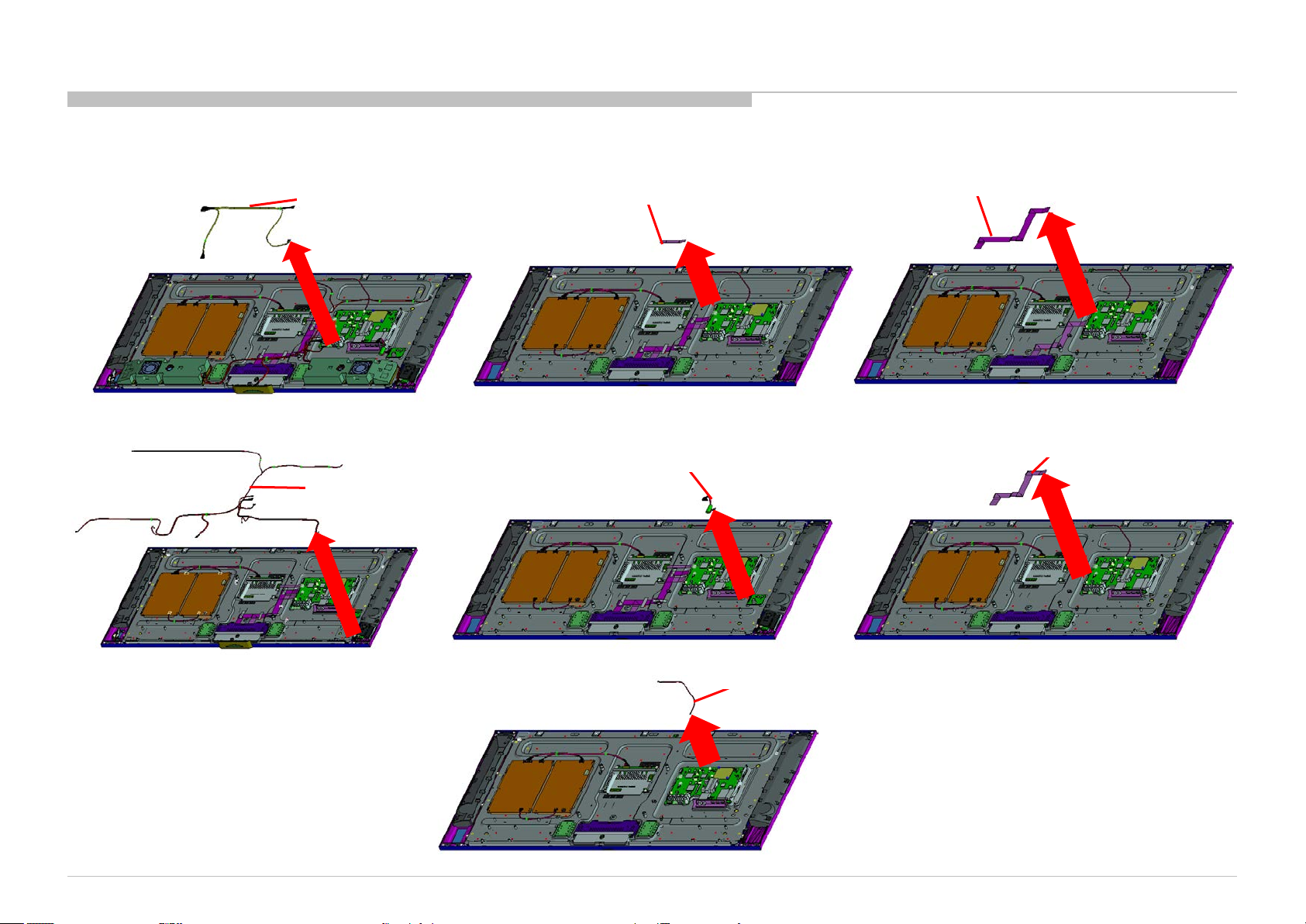
1-2. KD-65X9000A
WIRE DRESSING-1
DISASSEMBLY
1 2
1
3
2
3
KD-55/65X9000A(CH)
98
Page 99

1-2. KD-65X9000A
WIRE DRESSING-2
DISASSEMBLY
KD-55/65X9000A(CH)
99
Page 100

1-2. KD-65X9000A
WIRE DRESSING-3
BAF Board
DISASSEMBLY
CX Board
BAF Board
KD-55/65X9000A(CH)
CX Board
100
 Loading...