

Page 1
4-102-730-21(1)
Sony Corporation http://www.sony.net
Printed in U.S.A.
KD-34XBR960
Operating Instructions
© 2004 Sony Corporation
Page 2
WARNING
To reduce the risk of fire or shock hazard, do not expose the TV to
rain or mois ture.
CAUTION
RISK OF ELECTRIC SHOCK
DO NOT OPEN
ATTENTION
RISQUE DE CHOC ELECTRIQUE,
NE PAS OUVRIR
PRECAUCION
RIESGO DE CHOQUE ELECTRICO
NO ABRIR
CAUTION: TO REDUCE THE RISK OF ELECTRIC SHOCK,
DO NOT REMOVE COVER (OR BACK).
NO USER-SERVICEABLE PARTS INSIDE.
REFER SERVICING TO QUALIFIED SERVICE PERSONNEL.
This symbol is intended to alert the user to the
presence of uninsulated “dangerous voltage”
within the product’s enclosure that may be of
sufficient magnitude to constitute a risk of
electr ic shock to persons.
This symbol is intended to alert the user to the
presence of important operating and maintenance
(servicing) instructions in the literature
accompanying the appliance.
CAUTION
TO PREVENT ELECTRIC SHOCK, MATCH WIDE BLADE OF
PLUG TO WIDE S LOT, FULLY INSERT.
CAUTION
When usi ng TV games, computer s, and similar products with y our
TV, keep the brightness and contrast functions at low settings. If a
fixed (non-moving) pattern is left on the screen for long periods of
time at a high brightness or contrast setting, the image can be
permanently imprinted onto the screen. Continuously watching
the same program can cause the imprint of station logos onto the
TV screen. These types of imprints are not covered by your
warranty because they are the result of misuse.
Warning
The CRT in this product employs a protective film on the face. This
film must not be removed as it serves a safety function and
removal will increase the risk of serious injury.
Note on Caption Vision
This television receiver provides display of television closed
captioning in accordance with §15.119 of the FCC rules.
Note on Cleaning the TV
Clean the TV with a soft, dry cloth. Never use strong solvents such
as thinner or benzine, which might damage the finish of the
cabinet.
Note to CATV System Installer
This reminder is provided to call the CATV system installer ’s
attention to Article 820-40 of the National Electrical Code (NEC)
that provides guidelines for proper grounding and, in particular,
specifies that the cable ground shall be connected to the grounding
system of the building, as close to the point of cable entry as
practical.
Use of this television receiver for other than priv ate viewing of
programs broadcast on UHF or VHF or transmitted by cable
companies for the use of the general public may require
authorization from the broadcaster/cable company and/or
program owner.
NOTIFICATION
This equipment has been tested and found to comply with the
limits for a Class B digital device pursuant to Part 15 of the FCC
Rules. These limits are designed to provide reasonable protection
against harmful interference in a residential installation. This
equipment generates, uses, and can radiate radio frequency energy
and, if not installed and used in accordance with the instructions,
may cause harmful interference with radio communications.
However, there is no guarantee that interference will not occur in a
particular installation. If this equipment does cause harmful
interference to radio or television reception, which can be
determined by turning the equipment off and on, the user is
encouraged to try to correct the interference by one or more of the
following measures:
❑ Reorient or relocate the receiving antennas.
❑ Increase the separation between the equipment and receiver.
❑ Connect the equipment into an outlet on a circuit different
from that to which the receiver is connected.
❑ Consult the dealer or an experienced radio/TV technician for
help.
You are cautioned that any changes or modifications not
expressly approved in this manual could void your authority
to operate this equipment.
Installing
To prevent internal heat buildup, do not block the ventilation
❑
openings.
❑ Do not install the TV in a hot or humid place, or in a place
subject to excessive dust or mechanical vibration.
❑ The AC power cord is attached to the rear of the TV with
hooks. Do not attempt to remove the cord from these hooks.
Doing so could cause damage to the TV.
Owner’s Record
The model and serial numbers are provided on the front of this
instruction manual and at the rear of the TV. Refer to them
whenever you call upon your Sony dealer regarding this product.
Note
This digital television is capable of receiving analog basic, digital
basic and digital premium cable television programming by direct
connection to a cable system providing such programming. A
security card provided by your cable operator is required to view
encrypted digital programming. Certain advanced and interactive
digital cable services such as video-on-demand, a cable operator's
enhanced program guide and data-enhanced television services
may require the use of a set-top box. For more information call
your local cable operator.
This television also includes a QAM demodulator which should
allow you to receive unscrambled digital cable television
programming via subscription service to a cable service provider.
Availability of digital cable television programming in your area
depends on the type of programming and signal provided by your
cable service provider.
1
Page 3
IMPORTANT SAFEGUARDS
For your protection, please read thes e instructions completely, and
keep this manual for future reference.
Carefully observe and comply with all warnings, cautions and
instructions placed on the set, or described in the operating
instructions or service manual.
WARNING
To guard against injury, the following basic safety precautions
should be observed in the installation, use, and servicing of the set.
Use
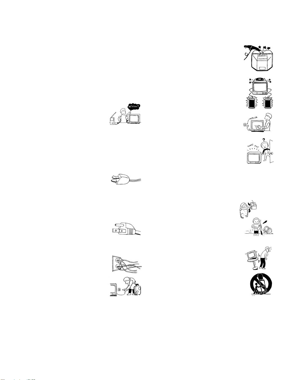
Power Sources
This set should be operated only from the type
of power source indicated on the serial/model
plate. If you are not sure of the type of electrical
power supplied to your home, consult your
dealer or local power company. For those sets
designed to operate from batt ery power, refer
to the operating instructions.
Grounding or Polarization
This set is equipped with a polarized AC power cord plug (a plug
having one blade wider than the other), or with a three-wire
grounding type plug (a plug having a third pin for grounding).
Follow the instructions below:
For the set with a polarized AC power cord plug
This plug will fit into the power outlet only one
way. Thi s is a safe ty fe ature. If you are unab le to
insert the plug fully into the outlet, try reversing
the plug. If the plug should s till fail to fit, conta ct your elect rician to
have a suitable outlet installed. Do not defeat the safety purpose of
the polarized p lug by forcing it in.
Alternate Warning
For the set with a three-wire grounding type AC plug
This plug will only fit into a grounding-type
power outlet. This is a safety feature. If you are
unable to insert the plug into the outlet, contact
your electrician to have a suitable outlet installed.
Do not defeat the safety purpose of the grounding plug.
Overloading
Do not overload wall outlets, extension cords or
convenience receptacles beyond their capacity,
since this can result in fire or electric shock.
Always turn the set off when it is not to be
used. When the set is left unattended and
unused for long periods of time, unplug it
from the wall outlet as a precaution against
the possibility of an internal malfunction that
could create a fire hazard.
Do not disconnect the antenna or the power cord during a heavy
storm. Lightning may strike while you are holding the cable or
cord, causing serious injury. Turn off your TV and wait for the
weather to improve.
Memory Stick
To protect small children from injury from Memory Stick Media,
remove all Memory Stick media from the TV’s Memory Stick slot
and store it in a safe location when it is not in use.
Object and Liquid Entry
Never push objects of any kind into the set
through the cabinet slots as they may touch
dangerous voltage points or short out parts that
could result in a fire or electric shock. Never spill
liquid of any kind on the set.
Attachments
Do not use attachments not recommended by the
manufacturer, as they may cause hazards.
Do not place any objects, especially heavy objects,
on top of the set. The object may fall from the set,
causing injury.
Cleaning
Unplug the set from the wall outlet before
cleaning or polishing it. Do not use liquid
cleaners or aerosol cleaners. Use a cloth lightly
dampened with water for cleaning the exterior
of the set.
If a snapping or popping sound from a TV set is
continuous or frequent while the TV is operating,
unplug the TV and consult your dealer or service
technician. It is normal for some TV sets to make
occasional snapping or popping sounds,
particularly when being turned on or off.
Installation
Always use two or more people to lift or move the set. The set is
heavy and the bottom surface is flat. Serious injury can result from
trying to move the set by yourself alone, or from unsteady
handling. Inst all the set on a stable, level surface.
Water and Moisture
Do not use power-line operated sets near
water — for example, near a bathtub,
washbowl, kitchen sink, or laundry tub, in a
wet basement, or near a swimming pool, etc.
Accessories
Do not place the set on an unstable cart, stand,
tripod, bracket, table or shelf. The set may fall,
causing serious injury to a child or an adult, and
serious damage to the set. Us e only a cart or stand
recommended by the manufacturer for the
specific model of TV. Any mounting of the
product should follow the manufacturer’s
instructions, and should use a mounting
accessory recommended by the manufacturer. An
appliance and cart combination should be moved
with care. Quick stops, excessive force, and
uneven surfaces may cause the appliance and cart
combination to overturn.
Disconnect all cables and cords from the set before attempting to
move the set.
Do not allow children or pets to climb up onto, or push against, the
set. The set may fall, causing serious injury.
2
Page 4
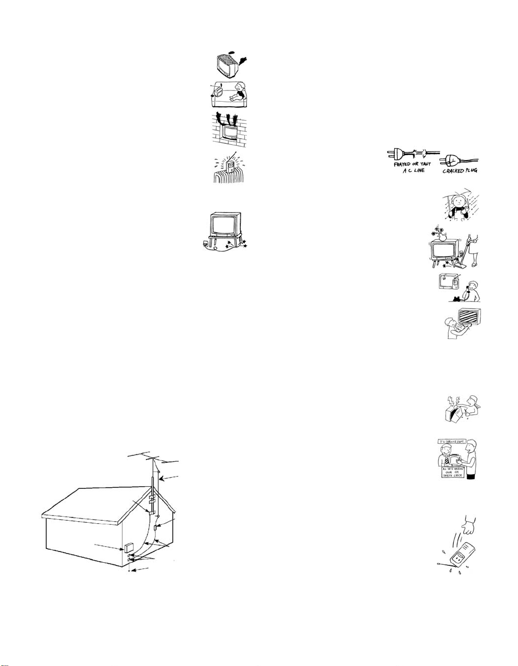
Ven til ati on
The slots and openings in the cabinet and in the
back or bottom are provided for necessary
ventilation. To ensure reliable operation of the set,
and to protect it from overheating, these slots and
openings must never be blocked or covered.
❑ Never cover the slots and openings with a
cloth or other materials.
❑ Never block the slots and openings by
placing the set on a bed, sofa, rug or other
similar surface.
❑ Never place the set in a confined space, such
as a bookcase, or built-in cabinet, unless
proper ventilation is provided.
❑ Do not place the set near or over a radiator
or heat register, or where it is exposed to direct sunlight.
Power Cord Protection
Do not allow anything to rest on or roll over the
power cord, and do not place the set where the
power cord is subject to wear or abuse.
Antennas
Outdoor Antenna Grounding
If an outdoor antenna is installed, follow the precautions below. An
outdoor antenna system should not be located in the vicinity of
overhead power lines or other electric light or power circuits, or
where it can come in contact with such power lines or circuits.
WHEN INSTALLING AN OUTDOOR ANTENNA SYSTEM,
EXTREME CARE SHOULD BE TAKEN TO KEEP FROM
CONTACTING SUCH POWER LINES OR CIRCUITS AS
CONTACT WITH THEM IS ALMOST INVARIABLY FATAL.
Be sure the antenna system is grounded so as to provide some
protection against voltage surges and built-up sta tic charges.
Section 810 of the National Electrical Code (NEC) in USA and
Section 54 of the Canadian Electrical Code in Canada provide
information with respect to proper grounding of the mast and
supporting structure, grounding of the lead-in wire to an antenna
discharge unit, size of grounding conductors, location of antenna
discharge unit, connection to grounding electrodes, and
requirements for the grounding electrode.
Antenna Grounding According to the National
Electrical Code, ANSI/NFPA 70
Antenna lead-in wire
Ground clamp
Antenna discharge unit
(NEC Section 810-20)
Electric service
equipment
NEC: National Electrical Code
Ground ing conductors
(NEC Section 810-21)
Ground clamps
Power service grounding electrode
system (NEC Art 250 Part H)
Lightning
For added protection for this television receiver during a lightning
storm, or when it is left unattended and unused for long periods of
time, unplug it from the wall outlet and disconnect the antenna.
This will prevent damage to the receiver due to lightning and
power line surges.
Service
Damage Requiring Service
Unplug the set from the wall outlet and refer servicing to q ualified
service personnel under the following conditions:
❑ When the power cord or plug
is damaged or frayed.
❑ If liquid has been spilled into
the set or objects have fallen into the
product.
❑ If the set has been exposed to rain or
water.
❑ If the set has been subject to excessive
shock by being dropped, or the cabinet
has been damaged.
❑ If the set does not operate normally when
following the operating instructions.
Adjust only those controls that are
specified in t he oper ating instructions.
Improper adjustment of other controls
may result in damage and will often
require extensive work by a qualified
technician to restore the set to normal
operation.
❑ When the set exhibits a distinct change in performance, it
indicates a need for service.
Servicing
Do not attempt to service the set y ourself since
opening the cabinet may expose you to dangerous
voltage or other hazards. Refer all servicing to
qualified service personnel.
Replacement Parts
When replacement parts are required, be sure the
service technician certifies in writing that he has
used replacement parts specified by the
manufacturer that have the same characteristics as
the original parts.
Unauthorized substitutions may result in fire, electric shock or
other hazards.
Safety Check
Upon completion of any service or repairs to the
set, ask the service technician to perform routine
safety checks (as specified by the manufacturer) to
determine that the set is in safe operating
condition, and to so certify. When the set reaches
the end of its useful life, improper disposal could
result in a picture tube implosion. Ask a qualified
service technician to dispose of the set.
3
Page 5

Trademark Information
WOW, TruSurround and the symbol are trademarks of SRS
Labs, Inc. WOW and TruSurround technology are incorporated
under license from SRS Labs, Inc.
Manufactured under license from Dolby
Labora tories Licensing Corporation. Dolby
and the double-D symbol are trademarks of
Dolby Laboratories Licensing Corporation.
Manufactured under license from BBE Sound, Inc. Licensed by BBE
Sound, Inc. under USP4638258, 5510752 and 5736897. BBE and BBE
symbol are registered trademarks of BBE Sound, Inc.
This TV incorporates High-Definition
Multimedia Interface (HDMI™)
High-Definition Multimedia Interface are trademarks or registered
trademarks of HDMI Licensing LLC.
CableCARD™ is a trademark of Cable Television Laboratories, Inc.
Wega, FD Trinitron, Steady Sound, Digital Reality Creation,
CineMotion, Memory Stick, Memory Stick Duo, Memory Stick
PRO, Memory Stick PRO Duo, MagicGate, Super Fine Pitch, MID,
Clear Edge, Twin View, ClearEdge VM and HD Detailer are
trademarks of Sony Corporation. i.LINK is a trademark of Sony
Corporation and used only to designate that a product contains an
IEEE 1394 connector. All products with an i.LINK connector may
not communicate with each other.
technology. HDMI, the HDMI logo and
4
Page 6

Contents
Introducing the FD Trinitron Wega
Overview ....................................................................................................... 9
Presenting the FD Trinitron Wega ............................................................... 9
Package Contents.............................................................................. 9
Features ............................................................................................ 9
Setting Up the TV
Overview .....................................................................................................13
About the AC Power Cord............................................................... 13
TV Controls and Connectors.......................................................................14
Front Panel .....................................................................................14
Rear Panel ....................................................................................... 15
Basic Connections: Connecting a Cable or Antenna.................................17
About Using CableCARD .................................................................17
Cable or Antenna Only ....................................................................18
Cable and Antenna Only .................................................................19
Cable Box and Cable Only ............................................................... 20
Cable Box Only ................................................................................ 21
Connecting Optional Equipment ...............................................................22
Making Video Connections ..............................................................23
About Using S VIDEO ...................................................................... 23
VCR and Cable ................................................................................24
VCR and Cable Box .........................................................................26
Two VCRs for Tape Editing ..............................................................28
Satellite Receiver.............................................................................. 30
Satellite Receiver and VCR ...............................................................32
DVD Player with Component Video Connectors...............................34
DVD Player with S VIDEO and Audio Connectors ............................. 36
Camcorder ......................................................................................37
Audio Receiver ................................................................................38
DVI-Equipped Device .......................................................................39
HDMI-Equipped Device .................................................................... 40
Connecting a Device with an Optical IN Connector .................................41
Using the CONTROL S Feature ...................................................................42
Using CableCARD ........................................................................................43
About Using CableCARD .................................................................43
Activating CableCARD Service ......................................................... 43
Removing the CableCARD ...............................................................44
Setting Up the Channel List .......................................................................45
Using Initial Setup ............................................................................ 45
5
Page 7

Using the Remote Control
Overview .....................................................................................................47
Inserting Batteries.......................................................................................47
Button Descriptions ....................................................................................48
Programming the Remote Control ............................................................51
Using the Features
Overview .....................................................................................................53
Watching TV ................................................................................................54
Using the Program Guide ........................................................................... 55
Using the Scrolling Index ...........................................................................57
Using Screen Mode .....................................................................................58
Using Twin View .........................................................................................60
Using Favorite Channels .............................................................................63
Using the Freeze Function..........................................................................65
Using Other Equipment with Your TV Remote Control...........................66
Outside Panel ..................................................................................48
Inside Panel .....................................................................................50
Using Additional Program Guide Options.........................................56
Factors Affecting Scrolling Index ......................................................57
Using Screen Mode with Standard Definition (480i/480p) Sources ...58
Using Screen Mode with High-Definition (720p/1080i) Sources........59
Displaying Twin Pictures .................................................................. 60
Factors Affecting Twin View ............................................................ 60
Activating the Picture ......................................................................61
Changing the Picture Size ................................................................62
Using the Channel Menu ................................................................. 63
Using the Favorite Channels Guide .................................................. 64
All Equipment..................................................................................66
Operating a VCR .............................................................................66
Operating a Satellite Receiver ..........................................................66
Operating a Cable Box.....................................................................67
Operating a DVD Player ...................................................................67
Operating a DVD/VCR Combination Unit .........................................68
Using the Memory Stick Viewer
About Memory Stick ................................................................................... 69
Inserting and Removing a Memory Stick .................................................. 72
Using the Memory Stick Index ...................................................................74
Viewing Photos ........................................................................................... 76
Other Info SETUP WelcomeSETUP SETUPSETUP
6
Features ..........................................................................................69
Memory Stick Compatibility ............................................................. 70
Memory Stick Functionality ..............................................................70
File Compatibility .............................................................................71
Trademark Information .................................................................... 71
Inserting a Memory Stick ................................................................. 72
Removing a Memory Stick ............................................................... 73
Using the Memory Stick Index ......................................................... 75
Photo Controls ................................................................................ 76
Photo Menu Bar Options ................................................................. 77
Using Zoom and Pan .......................................................................78
Using Rotate....................................................................................78
Page 8

Using i.LINK
Using the Menus
Playing Movies ............................................................................................ 79
Movie Controls................................................................................79
Movie Menu
Bar Options ..............................................................................80
Memory Stick Index Menu Bar Options .................................................... 81
Slide Show Menu Options ...............................................................81
Contents Menu Options ..................................................................82
Memory Stick Menu ........................................................................82
Notes on Using Memory Stick Media ........................................................83
About DCF File Names ..................................................................... 83
Memory Stick Precautions................................................................84
About i.LINK ................................................................................................85
Using i.LINK Cables.......................................................................... 85
Connecting i.LINK Devices ...............................................................86
Selecting an i.LINK Device ..........................................................................88
Using the i.LINK Control Panel...................................................................89
Notes About Controlling i.LINK Devices ...........................................90
i.LINK Setup ................................................................................................. 91
Notes on i.LINK................................................................................91
Overview .....................................................................................................93
Navigating Through Menus .......................................................................93
Using the Video Menu................................................................................94
Using the Audio Menu ...............................................................................97
Using the Screen Menu .............................................................................. 99
Using the Channel Menu ..........................................................................100
Using the Parent Menu............................................................................. 102
Using the Setup Menu..............................................................................105
Using the Applications Menu...................................................................108
Welcome SETUP Other InfoSETUP SETUPSETUP
Other Information
Overview ...................................................................................................111
Glossary ..................................................................................................... 112
Contacting Sony ........................................................................................ 113
Troubleshooting........................................................................................113
Twin View .................................................................................... 113
Remote Control .............................................................................114
CableCARD ...................................................................................114
Channels .......................................................................................115
Memory Stick ................................................................................116
Audio ............................................................................................117
Video ............................................................................................118
General ......................................................................................... 118
Specifications ............................................................................................ 120
Optional Accessories................................................................................. 121
Index .......................................................................................................... 123
7
Page 9

Page 10

Introducing the FD Trinitron Wega
Overview
This chapter describes the contents of the package in which the TV is
shipped and provides an overview of the features of your Wega TV.
Presenting the FD Trinitron Wega
The FD Trinitron Wega (pronounced VAY-GAH) is characterized by
outstanding contrast, uncompromising accuracy, and corner-tocorner detail.
You will recognize the superiority of Wega technology almost
immediately. The first thing you will probably notice is minimal glare
from the flat picture tube. This flat-screen technology improves
picture detail without distortion, unlike conventional curved screens.
The FD Trinitron delivers outstanding image detail not only at the
screen center, but also at the corners — so you can enjoy a bright,
clear picture from any location in a room.
Package Contents Along with your new Trinitron TV, the packing box contains a
remote control and two AA (R6) batteries. These items are all you
need to set up and use the TV.
Features Some of the features that you will enjoy with your new TV include:
❑ Built-in Digital Television Receiver: Yo u can w a tch d i g i t al
television programs and enjoy the improved audio/video quality
offered by these programs. With high-definition signal reception,
you can watch TV signals broadcast in HDTV for the clearest
possible broadcast picture.
9
Page 11

❑ CableCARD slot: Provides cable subscribers with access to
digitally encrypted cable channels — without the need for a settop box — that will enable you to receive not only standard
definition but also high definition television. The CableCARD,
which is provided by your cable TV company, is inserted into the
TV’s rear panel CableCARD slot. After the service is activated
with your cable TV company, the card replaces the need for a
separate set-top box. (Check with your cable TV company about
CableCARD service details, limitations, pricing, and availability.
For more information about CableCARD in this manual, see
pages 17 and 43.)
❑ Wide Screen Mode: Watch conventional 4:3 aspect ratio
broadcasts in wide screen (16:9) mode.
❑ Super Fine Pitch CRT: Created especially for displaying high
resolution pictures, the new Super Fine Pitch CRT — along with a
new electron gun and high intensity luminescent phosphor —
improves image resolution, providing the highest picture quality
reproduction from corner to corner.
❑ DRC
®
(Digital Reality Creation) Multifunction V1: Unlike
conventional line doublers, the DRC Multifunction feature
replaces the signal’s NTSC waveform with the near-HD
equivalent, while doubling the number of vertical and horizontal
lines. This results in four times the density for quality sources,
such as DVD, satellite, and digital camcorders. The Video Menu
allows you to select interlaced, progressive, or CineMotion™
output. The DRC Palette option lets you customize the level of
detail (Reality) and smoothness (Clarity) to create up to three
custom palettes.
❑ Scrolling Index: Lets you select programs from a series of
preview windows that scroll along the right side of the screen.
❑ Twin Vi e w
™
: Using the Multi-Image Driver (MIDX), Twin View
allows you to watch two programs side by side, with the ability
to zoom in one picture. You can watch pictures from two different
sources (1080i, 720p, 480p, and 480i) simultaneously. (Only the
left Twin View window can display 1080i, 720p, and 480p
sources.)
❑ Favorite Channels: Allows you to preview and select from 16 of
your favorite channels.
❑ ClearEdge VM
™
Velocity Modulation: Sharpens picture
definition by enhancing vertical lines.
❑ Steady Sound
®
: Equalizes volume levels so there is consistent
output between programs and commercials.
SETUP SETUP WelcomeSETUP SETUPSETUP
❑ Memory Stick
and movie (MPEG1) files that are stored on Memory Stick media.
®
Viewer: Lets you watch digital photo (JPEG)
10
Introducing
Page 12

❑ Component Video Inputs: Offers the best video quality for DVD
(480p, 480i), and digital set-top box (HD1080i, 720p) connections.
❑ HD Detailer
™
: Wideband video amplifier has a high bandwidth
frequency rating, which allows it to send more video information
to the screen, resulting in finer picture quality, especially for HD
sources.
❑ CineMotion
™
: Reverse 3-2 pulldown processing provides
optimal picture quality for film-based sources (media originally
shot in 24 frames-per-second format).
❑ Parental Control: V-Chip technology allows parents to block
unsuitable programming from younger viewers.
❑ HDMI (High-Definition Multimedia Interface): Provides an
uncompressed, all-digital audio/video interface between this TV
and any HDMI-equipped audio/video component, such as a settop box, DVD player, and A/V receiver. HDMI supports
enhanced, or high-definition video, plus two-channel digital
audio.
❑ i.LINK: Provides a secure digital interface to other digital home
entertainment devices. i.LINK allows for the secure transfer of
copyright-protected high-definition content between these
devices and your digital television.
Welcome SETUP SETUPSETUP SETUPSETUP
11
Page 13

Page 14
Setting Up the TV
Overview
This chapter includes illustrated instructions for setting up your TV.
Topi c Page(s)
TV Controls and Connectors 14-16
Basic Connections: Connecting a Cable or Antenna 17-21
Connecting Optional Equipment
VCR and Cable
VCR and Cable Box
Two VCRs for Tape Editing
Satellite Receiver
Satellite Receiver and VCR
DVD Player with Component Video Connectors
DVD Player with S VIDEO and Audio Connectors
Camcorder
Audio Receiver
DVI-Equipped Device
HDMI-Equipped Device
Connecting a Device with an Optical IN Connector 41
Using the CONTROL S Feature 42
Using CableCARD 43
Setting Up the Channel List 45
24
26
28
30
32
34
36
37
38
39
40
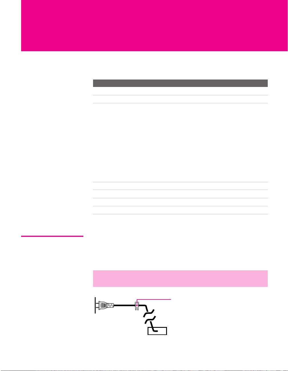
About the AC Power Cord
The AC power cord is attached to the rear of the TV with a hook. Use
caution when removing the AC plug from its holder. Gently slide the
plug upward to remove it from the hook. Once removed, the AC
power plug should automatically disengage from its stored location.
✍ Do not plug in the AC power cord until you have made all other
connections.
You can detac h
the cord from
this hook
AC power cord
13
Page 15
TV Controls and Connectors
Front Panel
I.LINK
1
2
S VIDEO
3
VIDEO 2 INPUT
L(MONO) -– AUDIO – R
VIDEO
4
6
5
i.LINK
MENU
7
8
9
TV/VIDEO
q;
VOLUME
+
CHANNEL
_
qa
PRO
qs
STD/DUO
qd
qf
i.LINK
STAND BY
qg
TIMER/
STAND BY
qh
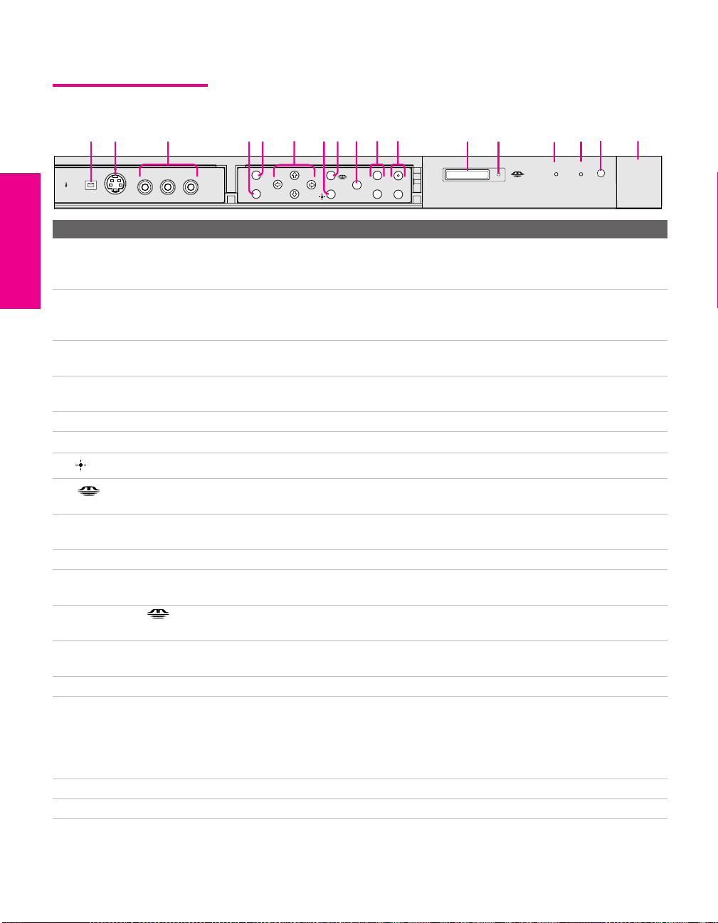
Item Description
1 i.LINK Connects to the i.LINK jack on your i.LINK-compatible portable device.
Provides a secure digital connection between your TV and your i.LINKcompatible portable device, such as a digital video camcorder.
2 S VIDEO
VIDEO 2 INPUT
Connects to the S VIDEO OUT jack on your camcorder or other video
equipment that has S VIDEO. Provides better picture quality than composite
video (3).
3 VIDEO/L(MONO)-AUDIO-R
VIDEO 2 INPUT
Connects to the composite A/V output jacks on your camcorder or other video
equipment.
4 MENU Press to display the Menu. Press again to exit from the Menu. For details, see
“Using the Menus” on page 93.
5 i.LINK Press to display the i.LINK Control Panel. For details, see page 89.
Vv B b Press Vv B b to move the TV’s on-screen cursor.
6
7
Press to select an item in the TV’s Menu.
8 Press to display the Memory Stick Menu. For details, see “Using the Memory
Stick Viewer” on page 69.
9 TV/VIDEO Press repeatedly to cycle through the video equipment connected to the TV’s
video inputs.
0 -VOLUME + Press to adjust the volume.
qa -CHANNEL+ Press to scan through channels. To scan quickly through channels, press and
hold down either CHANNEL button.
qs PRO STD/DUO Memory Stick insertion slot. For details, see “Inserting and Removing a Memory
Stick” on page 72.
qd Memory Stick LED When lit, indicates that the Memory Stick is being read. (Do not remove the
Memory Stick when the indicator is lit.)
qf i.LINK STAND BY LED When lit in orange, indicates that i.LINK Standby is on. For details, see page 106.
qg TIMER/STAND BY LED Blinks when the TV is turned on, then shuts off when the picture is displayed. If
the LED blinks continuously, this may indicate the TV needs service (see
“Contacting Sony” on page 113). When lit, indicates one of the timers is set.
When the timer is set, this LED will remain lit even if the TV is turned off. For
details, see page 108.
qh Infrared Receiver (IR) Receives IR signals from the TV’s remote control.
SETUP SETUP SETUPSETUP SetupSETUP
qj POWER Press to turn on and off the TV.
qj
POWER
14
Page 16
Rear Panel
1
2
SETUP Setup SETUPSETUP SETUPSETUP
qs
3
4
5
6
7
qa
q;
9
8
15
Page 17

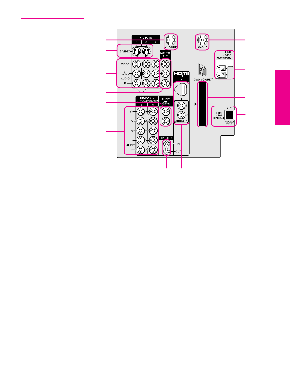
Jack Description
1 VHF/UHF RF input that connects to your VHF/UHF antenna or cable box.
2 S VIDEO IN 1/3 Connects to the S VIDEO OUT jack of your VCR or other video equipment that has
S VIDEO. S VIDEO provides better picture quality than either composite video (3)
or VHF/UHF (1) connections.
3 VIDEO IN 1/3/4
VIDEO/L(MONO)
-AUDIO-R
4 MONITOR OUT Lets you record the program you are watching to a VCR. When two VCRs are
5 AUDIO OUT (VAR/FIX) Connects to the left and right audio input jacks of your audio or video equipment.
6 HD/DVD IN 5/6
(1080i/720p/480p/480i)
7 CONTROL S
IN/OUT
8 HDMI
(VIDEO 7 IN)
9 DIGITAL AUDIO OPTICAL
OUTPUT
(DOLBY DIGITAL PCM)
0 CableCARD Slot Provides cable subscribers with access to digitally encrypted cable channels —
qa i.LINK
(2 inputs)
qs Cable RF input that connects to your cable signal.
Connect to the composite A/V output jacks on your VCR or other video
component. A fourth component A/V input jack (VIDEO 2) is located on the front
panel of the TV. This video connection provides better picture quality than the
VHF/UHF (1) connection.
connected, you can use the TV as a monitor for tape-to-tape editing (not available
with digital channels or with 480i, 480p, 720p, or 1080i when the input is set to
VIDEO 5, 6, or 7).
You can use these outputs to listen to your TV’s audio through your stereo system.
Connect to your DVD player’s or digital set-top box’s component video (Y, P
and audio (L/R) jacks. Component video provides better picture quality than 1,
2, or 3).
Allows the TV to receive (IN) and send (OUT) remote control signals to other Sony
infrared-controlled audio or video equipment that has the CONTROL S function.
HDMI (High-Definition Multimedia Interface) provides an uncompressed, alldigital audio/video interface between this TV and any HDMI-equipped
audio/video component, such as a set-top box, DVD player, and A/V receiver.
HDMI supports enhanced, or high-definition video, plus two-channel digital audio.
Connect to the optical audio input of an audio component that is Dolby* Digital and
PCM compatible.
without the need for a set-top box — that will enable you to receive not only
standard definition but also high definition television. The CableCARD, which is
provided by your cable TV company, is inserted into this slot. After the service is
activated with your cable TV company, the card replaces the need for a separate settop box. Check with your cable TV company about CableCARD service details,
limitations, pricing, and availability. For more information, see page 43.
Connects to the i.LINK jack on your i.LINK-compatible device. Provides a secure
digital connection between your TV and your i.LINK-compatible device.
B, PR)
* Dolby and the double-D symbol are trademarks of Dolby Laboratories Licensing Corporation.
SETUP SETUP SETUPSETUP SetupSETUP
16
Page 18

Basic Connections: Connecting a Cable or Antenna
The way in which you will connect your TV varies, depending on
how your home receives a signal (cable, cable box, antenna) and
whether or not you plan to connect a VCR.
If You Are Connecting See Page
Cable or Antenna Only
❏ No cable box or VCR
Cable and Antenna Only
❏ No cable box or VCR
Cable Box and Cable Only
❏ Cable box unscrambles only some
channels (usually premium channels)
❏ No VCR
Cable Box Only
❏ Cable box unscrambles all channels
❏ No VCR
If you are connecting a VCR
❑
See the connections described on pages 24 and 26.
18
19
20
21
About Using CableCARD
If you are planning to use a separate cable box for digital cable TV services, you may be able
to receive programming using this TV with the CableCARD instead — except in the following
circumstances:
SETUP Setup SETUPSETUP SETUPSETUP
❑ Your cable TV company does not provide CableCARD service in your viewing area.
❑ You want to access your cable TV company’s interactive or advanced features (such as
video-on-demand or, in some cases, pay-per-view). At this time, these services require a
bidirectional link, which are only available through the use of a separate set-top box.
CableCARD is currently a unidirectional device only, and cannot provide these advanced
services.
Check with your cable TV company for CableCARD service details, limitations, pricing, and
availability, all of which are determined by your cable TV company — not Sony. For
information on installing and activating CableCARD, see “Using CableCARD” on page 43.
17
Page 19
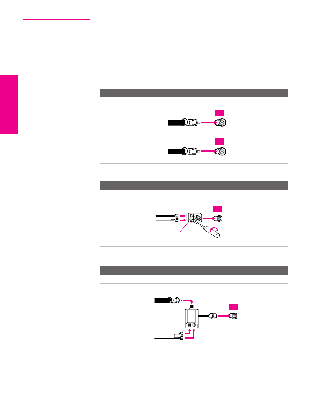
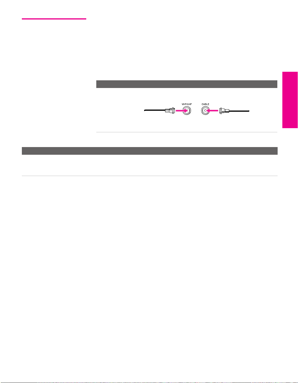
Cable or Antenna Only
For best results, use one of the following connections if you are connecting a
cable or an antenna and you:
❑
Do not need a cable box to unscramble channels. (If you have a
cable box, see pages 20-21.)
❑ Do not intend to connect a VCR. (If you have a VCR, see pages 24
and 26.)
The connection you choose depends on the cable type you have in
your home, as described below.
75-ohm coaxial cable (usually found in newer homes)
Cable Type Connect As Shown
VHF Only or
combined
VHF/UHF
75-ohm
coaxial
cable
TV
VHF/UHF
Cable
75-ohm
coaxial
cable
300-ohm twin lead cable (usually found in older homes)
Cable Type Connect As Shown
VHF Only or
UHF Only or
300-ohm twin
lead cable
TV
CABLE
TV
combined
VHF/UHF
Antenna connector
(not supplied)
75-ohm coaxial and 300-ohm twin lead cable (found in some homes)
Cable Type Connect As Shown
VHF and UHF
75-ohm
coaxial cable
VHF/UHF
TV
U/V mixer
(not supplied)
300-ohm twin
SETUP SETUP SETUPSETUP SetupSETUP
lead cable
VHF/UHF
18
Page 20
Cable and Antenna Only
For best results, use this connection if you:
❑
Have a cable and an antenna.
(This is convenient if you are using a separate rooftop antenna to
receive additional channels that are not provided by your cable
TV company.)
❑ Do not have a cable box or VCR. (If you have a cable box, see
pages 20 to 21. If you have a VCR, see pages 24 and 26.)
Cable Type Connect As Shown
Cable TV (CATV)
and Antenna
Notes on Using This Connection
To Do This ... Do This ...
Switch the TV’s input
between the cable and
antenna
Press ANT to switch back and forth between the TV’s VHF/UHF and CABLE
inputs.
SETUP Setup SETUPSETUP SETUPSETUP
Antenna cable CATV cable
19
Page 21
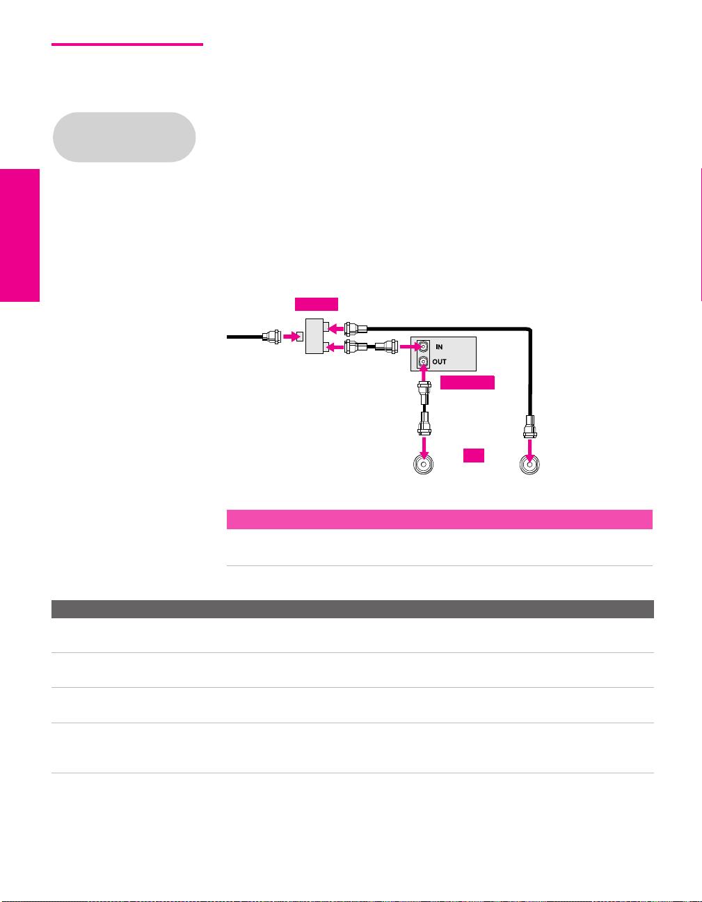
Cable Box and Cable Only
Before connecting a cable
box, see “About Using
CableCARD” on page 17.
For best results, use this connection if:
❑
Your cable TV company scrambles some channels, such as
premium channels (which requires you to use a cable box), but
does not scramble all channels.
❑ You do not have a VCR. (If you have a VCR, see pages 24 and 26.)
With this connection you can:
❑
Use the TV remote control to change channels coming through
the cable box to the TV’s VHF/UHF input jack. (You must first
program the remote control for your specific cable box; see
“Programming the Remote Control” on page 51.)
❑ Use the TV remote control to change channels coming directly
into the TV’s CABLE input. (The TV’s tuner provides a better
signal than the cable box.)
Splitter
CATV cable
Coaxial cable
Coaxial cable
About Using This Connection with Dual Picture (Twin View, etc.) Features
With this connection, you can use all the dual picture features for unscrambled channels
coming directly into the TV’s CABLE input jack.
Notes on Using This Connection
To Do This ... Do This ...
Use the cable box Tune the TV to the channel the cable box is set to (usually channel 3 or 4)
and then use the cable box to switch channels.
Set up the TV remote control
to operate the cable box
Activate the remote control to
operate the cable box
Switch
the TV’s input
between the cable box and
cable
Program the remote control. See “Programming the Remote Control” on
pages 51-52.
Press SAT/CABLE FUNCTION.
Press ANT to switch back and forth between the TV’s VHF/UHF (scrambled
channels) and CABLE (unscrambled) inputs.
Coaxial cable
Cable box
VHF/UHF
TV
CABLE
SETUP SETUP SETUPSETUP SetupSETUP
20
Page 22
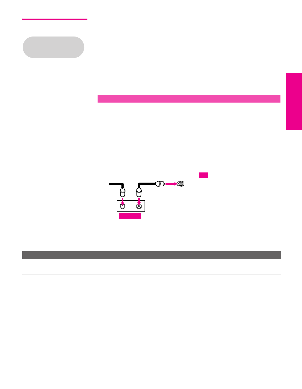
Cable Box Only For best results, use this connection if:
❑
Your cable TV company scrambles all channels, which requires
Before connecting a cable
box, see “About Using
CableCARD” on page 17.
you to use a cable box.
❑ You do not have a VCR. (If you have a VCR, see pages 24 and 26.)
With this connection you can:
❑
Use the TV remote control to change channels coming through
the cable box to the TV’s VHF/UHF jack. (You must first
program the remote control for your specific cable box.)
About Using This Connection with Dual Picture (Twin View, etc.) Features
With this connection, all channels come into the TV through your cable box and only one
unscrambled signal is sent to the TV, so you cannot use the dual picture features.. If
some of your channels are scrambled, but others are not, consider using the “Cable Box
and Cable” connection on page 20 instead.
To connect the cable box
1 Connect the CATV cable to the cable box’s input jack.
2 Use a coaxial cable to connect the cable box’s output jack to the
TV’s VHF/UHF jack.
CATV
cable
12
Coaxial cable
VHF/UHF
SETUP Setup SETUPSETUP SETUPSETUP
TV
IN
Cable box
OUT
3 Run Auto Program, as described in “Setting Up the Channel List”
on page 45.
Notes on Using This Connection
To Do This ... Do This ...
Use the cable box Tune the TV to the channel the cable box is set to (usually channel 3 or 4)
and then use the cable box to switch channels.
Set up the TV remote control
to operate the cable box
Activate the remote control to
operate the cable box
Program the remote control. See “Programming the Remote Control” on
pages 51.
Press SAT/CABLE FUNCTION.
21
Page 23

Connecting Optional Equipment
Use the directions in this section to connect the following optional
equipment:
If You Are Connecting See Page
VCR and Cable 24
VCR and Cable Box 26
Two VCRs for Tape Editing 28
Satellite Receiver 30
Satellite Receiver and VCR 32
DVD Player with Component Video
Connectors
DVD Player with S VIDEO and Audio
Connectors
Camcorder 37
Audio Receiver 38
DVI-Equipped Device 39
HDMI-Equipped Device 40
34
36
SETUP SETUP SETUPSETUP SetupSETUP
22
Page 24
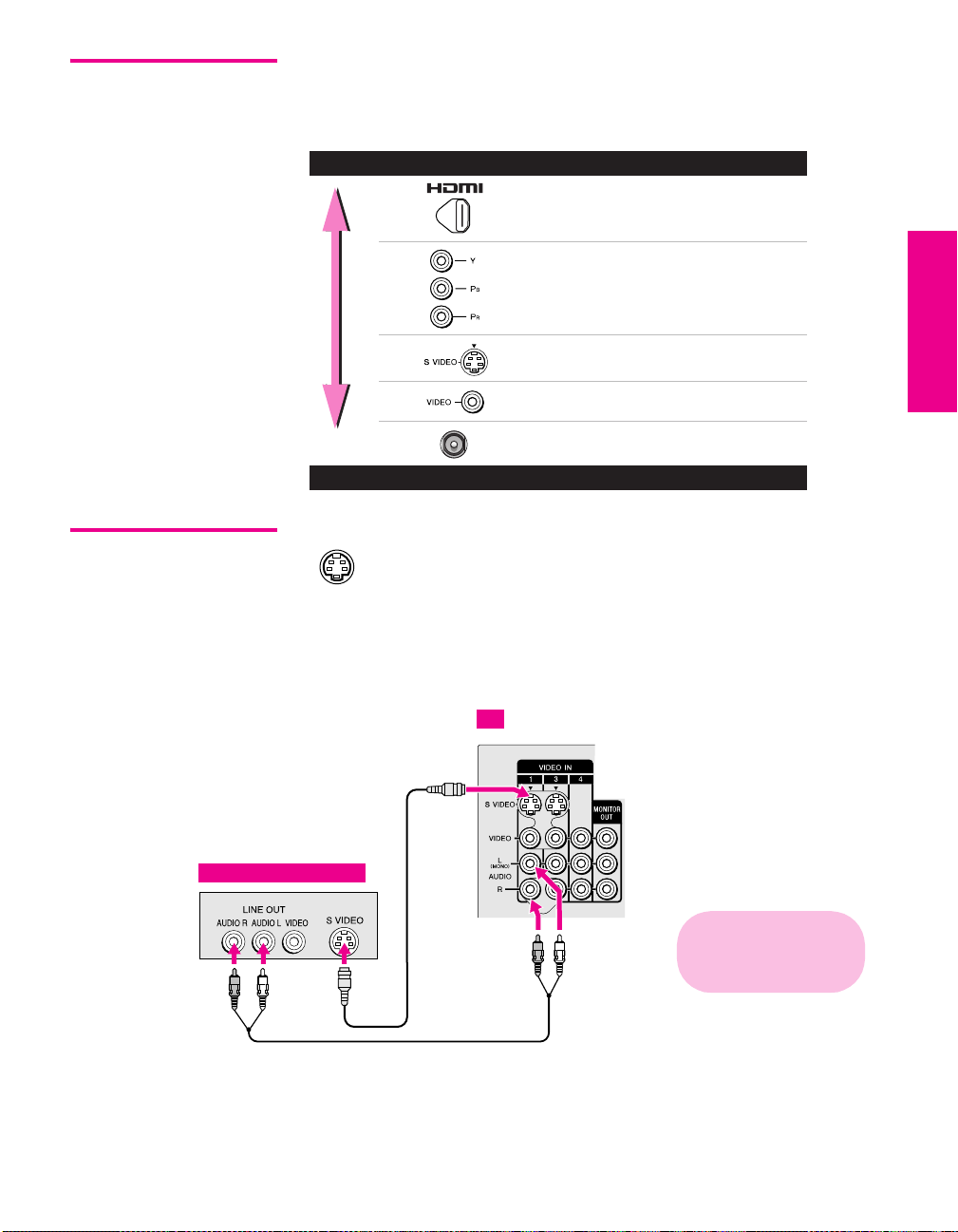
Making Video Connections
Your TV includes several types of video inputs. When connecting
your TV, use the inputs that are available on your components that
provide the best video performance, as described below.
Best Video Performance
HDMI (High-Definition
Multimedia Interface)
Component video
S VIDEO
Composite video
RF/Coaxial
Good Video Performance
SETUP Setup SETUPSETUP SETUPSETUP
About Using
SVIDEO
Example of an S VIDEO Connection
S VIDEO
Equipment with S VIDEO
If the optional equipment you are connecting has an S VIDEO
jack (shown at left), you can use an S VIDEO cable for
improved picture quality (compared to an A/V cable).
Because S VIDEO carries only the video signal, you also need
to connect audio cables for sound, as shown below.
TV
cable
Cables are often
color-coded to connectors.
Connect red to red,
white to white, etc.
Audio cable
23
Page 25
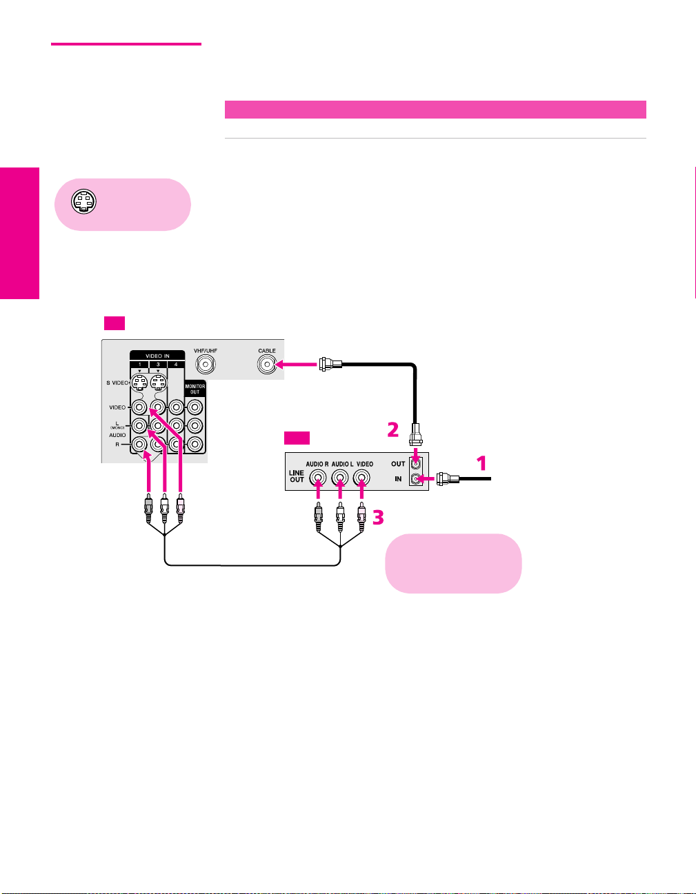
VCR and Cable For best results, use this connection if:
❑
Your cable TV company does not require you to use a cable box.
About Using This Connection with Dual Picture (Twin View, etc.) Features
With this connection, you can use all the dual picture features.
To connect the VCR and cable
Using
S VIDEO jacks?
See page 23.
1 Connect the CATV cable to the VCR’s VHF/UHF input jack.
2 Use a coaxial cable to connect the VCR’s VHF/UHF output jack
to the TV’s CABLE jack.
3 Use an A/V cable to connect the VCR’s A/V output jacks to the
TV’s A/V input jacks.
4 Run Auto Program, as described in “Setting Up the Channel List”
on page 45.
TV
Coaxial cable
VCR
CATV cable
A/V cable
Cables are often
color-coded to connectors.
Connect red to red,
white to white, etc.
SETUP SETUP SETUPSETUP SetupSETUP
24
Page 26

Notes on Using This Connection
To Do This ... Do This ...
Watch the VCR Press TV/VIDEO repeatedly to select the VCR input (VIDEO 1 in the
illustration).
Watch cable channels Press TV/VIDEO repeatedly to select the cable input (CABLE in the
illustration).
Set up the TV remote control
to operate the VCR
Activate the TV remote
control to operate the VCR
Control VCR functions with
the TV remote control
Label video inputs to easily
identify equipment connected
to the TV
If you have a non-Sony VCR, you must program the remote control. See
“Programming the Remote Control” on pages 51-52.
Open the outside cover, as shown on page 50. Then set the A/V slide switch
to the position you programmed for the VCR.
See “Operating a VCR” on page 66.
See the instructions for setting up Video Labels on page 105.
SETUP Setup SETUPSETUP SETUPSETUP
25
Page 27

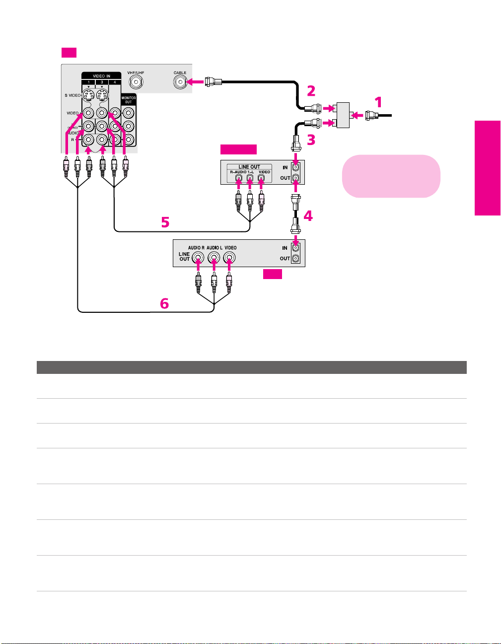
VCR and Cable Box For best results, use this connection if:
❑
Your cable TV company scrambles some channels, such as
Before connecting a cable
box, see “About Using
CableCARD” on page 17.
premium channels (which requires you to use a cable box), but
does not scramble all channels.
About Using This Connection with Dual Picture (Twin View, etc.) Features
With this connection, you can use all the dual picture features.
With this connection you can:
❑
Use the TV remote control to change channels coming through
the cable box. (You must first program the remote control for
your specific cable box; see “Programming the Remote Control”
on page 51.)
❑ Use the TV remote control to change channels coming directly
into the TV’s CABLE jack. (The TV’s tuner provides a better
signal than the cable box.)
❑ Record channels coming through the cable box and channels
coming directly into the TV.
To connect a VCR and cable box, you need:
❑
A splitter, which is a small, inexpensive device that you can
purchase at your local electronics store.
❑ Four coaxial cables.
❑ Two A/V cables or two S VIDEO cable with audio cables.
To connect the VCR and cable box
1 Connect the CATV cable to the single (input) jack of the splitter.
2 Use a coaxial cable to connect one of the splitter’s two output
jacks to the TV’s CABLE jack.
3 Use a coaxial cable to connect the splitter’s other output jack to
the cable box’s input jack.
4 Use a coaxial cable to connect the cable box’s output jack to the
VCR’s RF input jack.
5 Use an A/V cable to connect the cable box’s A/V output jacks to
Using
S VIDEO jacks?
See page 23.
the TV’s A/V input jacks.
6 Use an A/V cable to connect the VCR’s A/V output jacks to the
TV’s A/V input jacks.
7 Run Auto Program, as described in “Setting Up the Channel List”
on page 45.
SETUP SETUP SETUPSETUP SetupSETUP
26
Page 28
TV
A/V cable
A/V cable
Coaxial
cable
Cable box
Coaxial
cable
VCR
Splitter
(not supplied)
Cables are often
color-coded to connectors.
Connect red to red,
white to white, etc.
Coaxial
cable
CATV
cable
SETUP Setup SETUPSETUP SETUPSETUP
Notes on Using This Connection
To Do This ... Do This ...
Watch cable (unscrambled)
channels
Watch cable box (scrambled)
channels
Press TV/VIDEO repeatedly to select the cable input (CABLE in the
illustration).
Press TV/VIDEO repeatedly to select the cable box input (VIDEO 3 in the
illustration). Use the cable box to change channels.
Watch the VCR Press TV/VIDEO repeatedly to select the VCR input (VIDEO 1 in the
illustration).
Set up the TV remote control
to operate the cable box or
If you have a non-Sony VCR, you must program the remote control. See
“Programming the Remote Control” on pages 51-52.
VCR
Activate the remote control to
operate the cable box or VCR
For the cable box, press SAT/CABLE FUNCTION. For the VCR, open the outside
cover, as shown on page 50. Then set the A/V slide switch to the position
you programmed for the VCR.
Control specific cable box and
See “Operating a Cable Box” on page 67 and “Operating a VCR” on page 66.
VCR functions with the TV
remote control
Label video inputs to easily
See the instructions for setting up Video Labels on page 101.
identify equipment connected
to the TV
27
Page 29
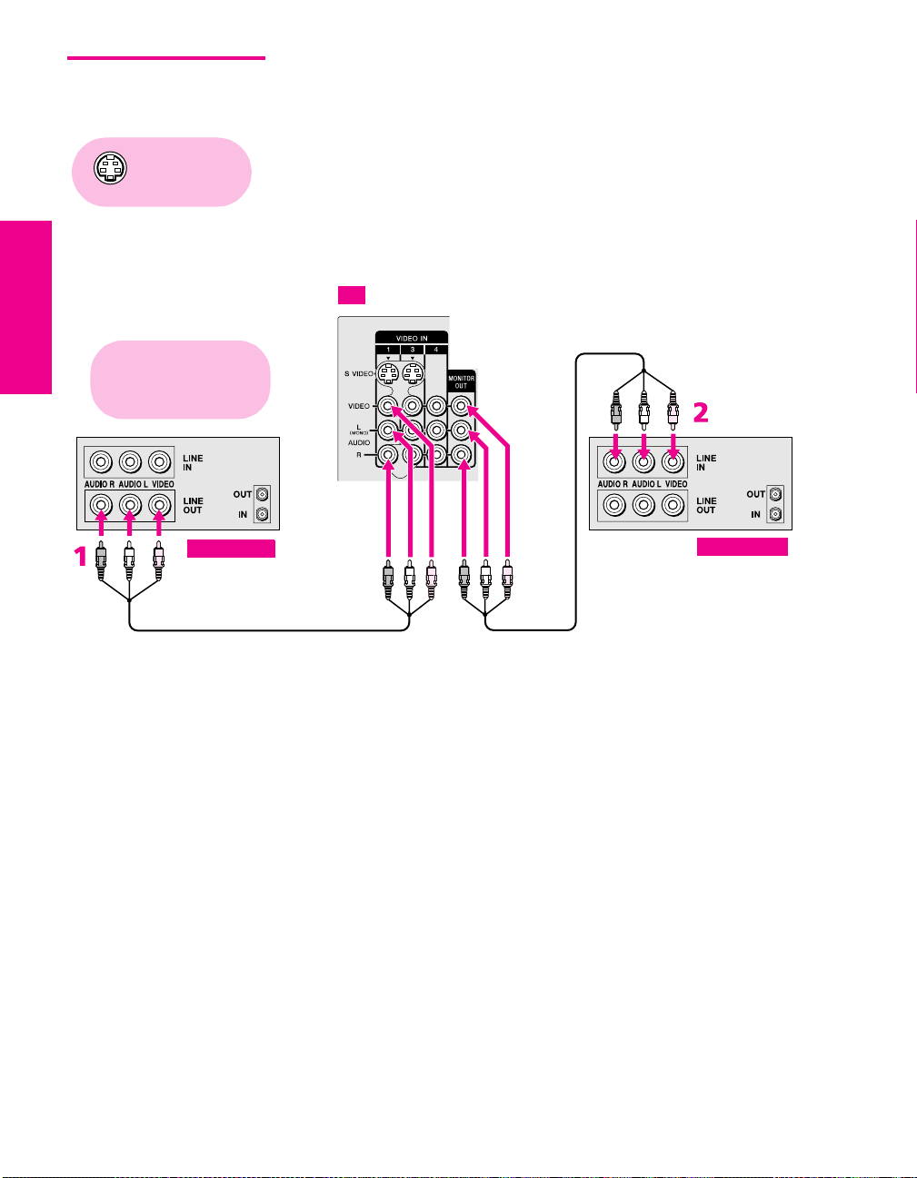
Two VCRs for Tape Editing
Connecting two VCRs lets you record from one VCR to the other. By
connecting them as shown below, you can view (monitor) what is
being recorded.
Using
S VIDEO jacks?
See page 23.
Cables are often
color-coded to connectors.
Connect red to red,
white to white, etc.
Playback VCR
A/V cable
To connect two VCRs for tape editing
1 Use an A/V cable to connect the playback VCR’s A/V output
jacks to the TV’s A/V input jacks.
2 Use an A/V cable to connect the recording VCR’s A/V input
jacks to the TV’s MONITOR OUT jacks.
TV
Recording VCR
A/V cable
SETUP SETUP SETUPSETUP SetupSETUP
28
Page 30

Notes on Using This Connection
To Do This ... Do This ...
View (monitor) what is being
recorded
Set up the TV remote control
to operate the VCR(s)
Activate the TV remote
control to operate the VCR(s)
Control VCR functions with
the TV remote control
Label video inputs to easily
identify equipment connected
to the TV
Press TV/VIDEO repeatedly to select the VCR input (VIDEO 1 in the
illustration above).
If you have a non-Sony VCR, you must program the remote control. See
“Programming the Remote Control” on pages 51-52.
Open the outside cover, as shown on page 50. Then set the A/V slide switch
to the position you programmed for the VCR.
See “Operating a VCR” on page 66.
See the instructions for setting up Video Labels on page 105.
SETUP Setup SETUPSETUP SETUPSETUP
29
Page 31

Satellite Receiver To connect a satellite receiver
1 Connect the satellite antenna cable to the satellite receiver’s
Using
S VIDEO jacks?
See page 23.
satellite input jack.
2 Use an A/V cable to connect the satellite receiver’s A/V output
jacks to the TV’s A/V input jacks.
3 Connect a CATV cable from your cable or antenna to the TV’s
CABLE jack.
4 Run Auto Program, as described in “Setting Up the Channel List”
on page 45.
TV
A/V cable
Satellite receiver
CATV cable
Satellite antenna
cable
Cables are often
color-coded to connectors.
Connect red to red,
white to white, etc.
SETUP SETUP SETUPSETUP SetupSETUP
30
Page 32

Notes on Using This Connection
To Do This ... Do This ...
Watch the satellite receiver Press TV/VIDEO repeatedly to select the satellite receiver input
(VIDEO 1 in the illustration).
Set up the TV remote control to operate the
satellite receiver
Activate the TV remote control to operate
the satellite receiver
Control satellite receiver functions with the
TV remote control
Label video inputs to easily identify
equipment connected to the TV
If you have a non-Sony satellite receiver, you must program
the remote control. See “Programming the Remote Control”
on pages 51-52.
Press SAT/CABLE FUNCTION.
See “Operating a Satellite Receiver” on page 66.
See the instructions for setting up Video Labels on page 105.
SETUP Setup SETUPSETUP SETUPSETUP
31
Page 33

Satellite Receiver and VCR
Using
S VIDEO jacks?
See page 23.
To connect a satellite receiver and VCR
1 Connect the CATV cable to the single (input) jack of the splitter.
2 Use a coaxial cable to connect one of the splitter’s two output
jacks to the TV’s CABLE jack.
3 Use a coaxial cable to connect the splitter’s other output jack to
the satellite receiver’s VHF/UHF input jack.
4 Connect the satellite antenna cable to the satellite receiver’s
satellite input jack.
5 Use a coaxial cable to connect the satellite receiver’s VHF/UHF
output jack to the VCR’s VHF/UHF input jack.
6 Use an A/V cable to connect the satellite receiver’s A/V output
jacks to the TV’s A/V input jacks.
7 Use an A/V cable to connect the VCR’s A/V output jacks to the
TV’s A/V input jacks.
8 Run Auto Program, as described in “Setting Up the Channel List”
on page 45.
CATV
cable
Splitter
(not supplied)
TV
A/V cable
Coaxial
cable
Satellite antenna
Coaxial
cable
Satellite receiver
Coaxial
cable
cable
Cables are often
color-coded to connectors.
Connect red to red,
white to white, etc.
VCR
SETUP SETUP SETUPSETUP SetupSETUP
A/V cable
7
32
Page 34

Notes on Using This Connection
To Do This ... Do This ...
Watch the satellite receiver Press TV/VIDEO repeatedly to select the VCR input (VIDEO 3 in the
illustration).
Watch the VCR Press TV/VIDEO repeatedly to select the input to which the VCR is connected
(VIDEO 1 in the illustration).
Set up the TV remote control
to operate the satellite
receiver or VCR
Activate the TV remote
control to operate the satellite
receiver or VCR
Control satellite receiver and
VCR functions with the TV
remote control
Label video inputs to easily
identify equipment connected
to the TV
If you have a non-Sony VCR or satellite receiver, you must program the
remote control. See “Programming the Remote Control” on pages 51-52.
For the satellite receiver, press SAT/CABLE FUNCTION. For the VCR, open the
outside cover, as shown on page 50. Then set the A/V slide switch to the
position you programmed for the VCR.
See “Operating a Satellite Receiver” on page 66 and “Operating a VCR” on
page 66.
See the instructions for setting up Video Labels on page 105.
SETUP Setup SETUPSETUP SETUPSETUP
33
Page 35

DVD Player with Component Video Connectors
For best results, use this connection if your DVD player has
component video (Y, P
To connect a DVD player with component video connectors
B, PR) jacks.
1 Use three separate component video cables to connect the DVD
player’s Y, P
the TV.
B and PR jacks to the Y, PB and PR jacks (VIDEO 5) on
✍ The Y, PB and PR jacks on your DVD player are sometimes labeled Y,
C
B and CR, or Y, B-Y and R-Y. If so, connect the cables to like colors.
2
Use an audio cable to connect the DVD player ’s audio output
jacks to the TV’s VIDEO 5 audio input jacks.
Component video cables
DVD player
TV
Cables are often
color-coded to connectors.
Connect red to red,
white to white, etc.
Audio cable
SETUP SETUP SETUPSETUP SetupSETUP
34
Page 36

Notes on Using This Connection
To Do This ... Do This ...
Watch the DVD player Press TV/VIDEO repeatedly to select the DVD input (VIDEO 5 in the
illustration).
Set up the TV remote control
to operate the DVD player
Activate the TV remote
control to operate the DVD
player
Control DVD functions with
the TV remote control
Label video inputs to easily
identify equipment connected
to the TV
If you have a non-Sony DVD player, you must program the remote control.
See “Programming the Remote Control” on pages 51-52.
Open the outside cover, as shown on page 50. Then set the A/V slide switch
to the position you programmed for the DVD player.
See “Operating a DVD Player” on page 67.
See the instructions for setting up Video Labels on page 105.
✍ You cannot record the signal from any equipment connected into the Y, PB,
P
R jacks.
SETUP Setup SETUPSETUP SETUPSETUP
35
Page 37

DVD Player with S VIDEO and Audio Connectors
Use this connection if your DVD player does not have component
video (Y, P
To connect a DVD player with A/V connectors
B, PR) jacks.
1 Use an audio cable to connect the DVD player’s audio output
jacks to the TV’s audio input jacks.
2 Use an S VIDEO cable to connect the DVD player’s S VIDEO
jack to the TV’s S VIDEO jack.
TV
DVD player
Notes on Using This Connection
To Do This ... Do This ...
Watch the DVD player Press TV/VIDEO repeatedly to select the DVD input (VIDEO 1 in the
illustration).
Set up the TV remote control
to operate the DVD player
Activate the TV remote
control to operate the DVD
player
Control DVD functions with
the TV remote control
Label video inputs to easily
identify equipment connected
to the TV
If you have a non-Sony DVD player, you must program the remote control.
See “Programming the Remote Control” on pages 51-52.
Open the outside cover, as shown on page 50. Then set the A/V slide switch
to the position you programmed for the DVD player.
See “Operating a DVD Player” on page 67.
See the instructions for setting up Video Labels on page 105.
S VIDEO
cable
Audio cable
Cables are often
color-coded to connectors.
Connect red to red,
white to white, etc.
SETUP SETUP SETUPSETUP SetupSETUP
36
Page 38

Camcorder For easy connection of a camcorder, the TV has front A/V input jacks.
If you prefer, however, you can connect the camcorder to the TV’s
rear A/V input jacks.
✍ If your camcorder is equipped with an i.LINK jack, you can connect it using
Using
S VIDEO jacks?
See page 23.
TV
I.LINK
S VIDEO
i.LINK instead of the A/V inputs. See “Using i.LINK” on page 85.
To connect a camcorder
1 Use A/V cables to connect the camcorder’s A/V output jacks to
the TV’s A/V input jacks.
VIDEO 2 INPUT
L(MONO) -– AUDIO – R
VIDEO
Cables are often
color-coded to connectors.
Connect red to red,
white to white, etc.
A/V cable
SETUP Setup SETUPSETUP SETUPSETUP
Camcorder
To A/V ou tp u t
If you have a mono camcorder, connect its audio output jack to the
TV’s L MONO audio jack.
Notes on Using This Connection
To Do This ... Do This ...
Watch the camcorder Press TV/VIDEO repeatedly to select the camcorder input (VIDEO 2 in the
illustration).
Label video inputs to easily
identify equipment connected
to the TV
See the instructions for setting up Video Labels on page 105.
37
Page 39

Audio Receiver For improved sound quality, you may want to play the TV’s audio
through your stereo system.
To connect an audio system
1 Use an audio cable to connect the TV’s audio output jacks to the
audio receiver ’s line input jacks.
TV
Cables are often
color-coded to connectors.
Connect red to red,
white to wh ite.
Audio cable
To line input
Receiver
2 Using the TV’s Audio Menu, set the Speaker option to Off. Then set
the
Audio Out option to Fixed or Variable, depending on how you want
to control the volume. For details, see “Using the Audio Menu”
on page 97.
3 Turn on the audio receiver, and then set the receiver’s line input
to the jack into which you connected the TV.
SETUP SETUP SETUPSETUP SetupSETUP
38
Page 40
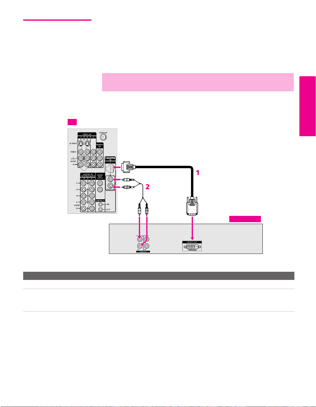
DVI-Equipped Device
TV
If you have a device, such as an HDTV receiver, that has DVI (Digital
Video Interface) output, use the following connection.
To connect a device that has DVI OUT:
1 Use an HDMI-to-DVI cable to connect the device’s DVI OUT jack
to the TV’s HDMI IN jack.
✍ You can purchase HDMI cables (or cable adapters) at your local electronics
store.
2 Use an audio cable to connect the device’s audio output jacks to
the TV’s HDMI analog audio input jacks.
HDMI-to-DVI cable
Audio cable
SETUP Setup SETUPSETUP SETUPSETUP
HDTV Receiver
Note on Using This Connection
To Do This ... Do This ...
Watch the DVI device Press TV/VIDEO repeatedly to select the VIDEO 7 input.
Label video inputs to easily
identify equipment connected
to the TV
See the instructions for setting up Video Labels on page 105.
39
Page 41

HDMI-Equipped Device
TV
If you have a device, such as an HDTV receiver, that has a High-
Definition Multimedia Interface (HDMI), use the following
connection.
To connect a device that has HDMI OUT:
1 Use the HDMI cable that came with your device to connect the
device’s HDMI OUT jack to the TV’s HDMI IN jack.
✍ HDMI cables transmit both audio and video signals. (Separate audio cables
are not necessary.) You can purchase HDMI cables at your local electronics
store.
HDMI cable
Note on Using This Connection
To Do This ... Do This ...
Watch the HDMI device Press TV/VIDEO repeatedly to select the VIDEO 7 input.
Label video inputs to easily
identify equipment connected
to the TV
See the instructions for setting up Video Labels on page 105.
SETUP SETUP SETUPSETUP SetupSETUP
40
HDTV Receiver
Page 42
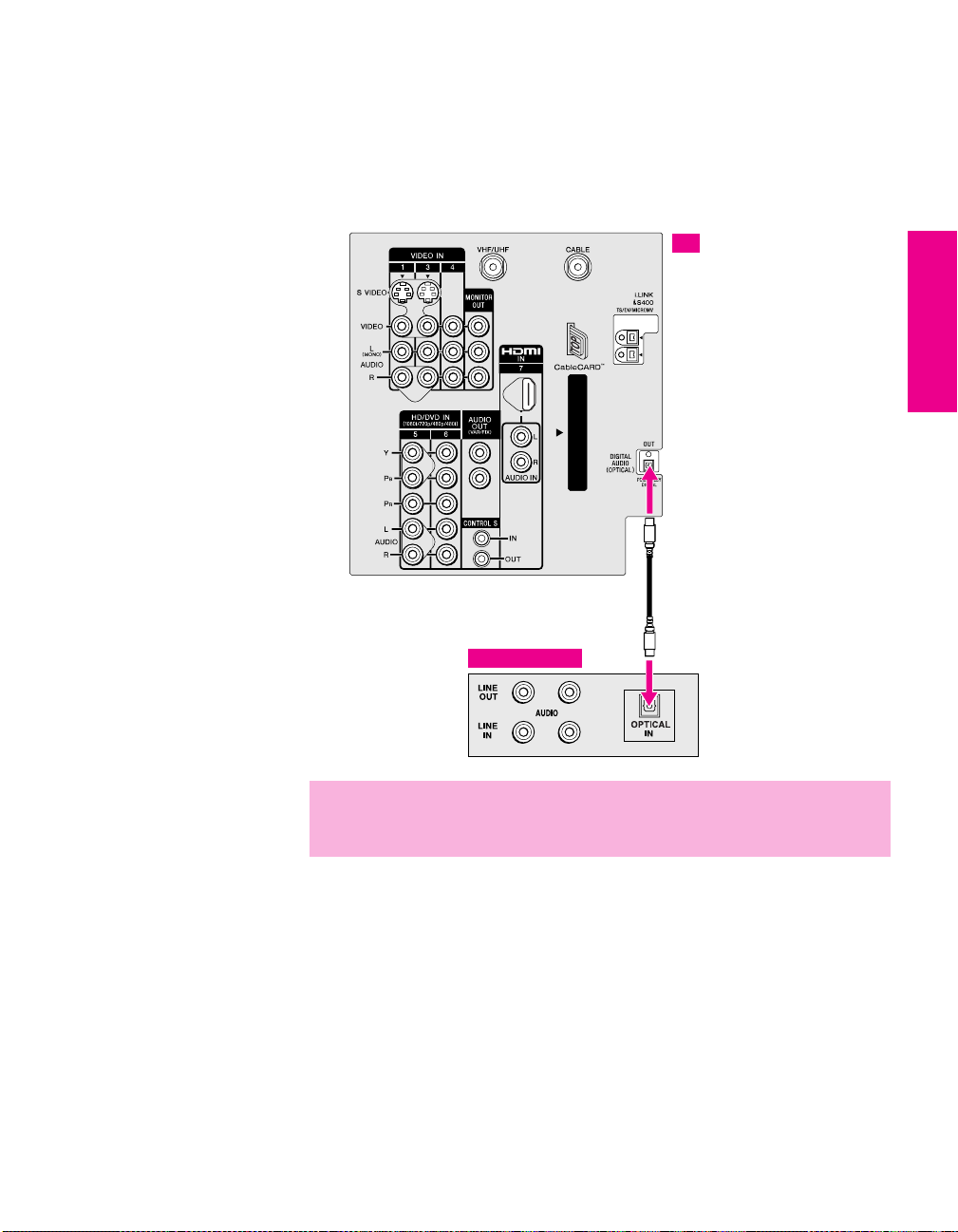
Connecting a Device with an Optical IN Connector
You can use the TV’s DIGITAL AUDIO OPTICAL output jack to
connect an audio device that is Dolby Digital and PCM compatible,
such as an audio amplifier.
❑ Using an optical cable, connect the TV’s DIGITAL AUDIO
OPTICAL output jack to the device’s audio optical input jack.
TV
Optical audio cable
SETUP Setup SETUPSETUP SETUPSETUP
Audio Amplifier
✍ Because all equipment does not output digital audio, you should also
connect the TV’s analog audio output jacks to the amplifier’s analog audio
input jacks, as described on page 38.
41
Page 43
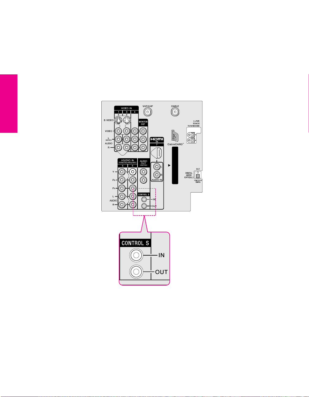
Using the CONTROL S Feature
CONTROL S allows you to control your system and other Sony
equipment with one remote control. In addition to allowing you to
control multiple devices with one remote control, the CONTROL S
feature allows you to always point your remote control at your TV,
instead of having to point it at the other equipment, which might be
hidden or out of direct line of sight.
Use CONTROL S IN to send signals to the TV.
Use CONTROL S OUT to send signals to connected equipment.
SETUP SETUP SETUPSETUP SetupSETUP
42
Page 44
Using CableCARD
CableCARD provides cable subscribers with access to digitally
encrypted cable channels — without the need for a set-top box — that
will enable you to receive not only standard definition but also high
definition television. The CableCARD, which is provided by your
cable TV company, is inserted into the TV’s rear panel CableCARD
slot. After the service is activated with your cable TV company, the
card replaces the need for a separate set-top box.
About Using CableCARD
If you are planning to use a separate cable box for digital cable TV services, you may be able
to receive programming using this TV with the CableCARD instead — except in the following
circumstances:
❑ Your cable TV company does not provide CableCARD service in your viewing area.
❑ You want to access your cable TV company’s interactive or advanced features (such as
video-on-demand or, in some cases, pay-per-view). At this time, these services require a
bidirectional link, which are only available through the use of a separate set-top box.
CableCARD is currently a unidirectional device only, and cannot provide these advanced
services.
Check with your cable TV company for CableCARD service details, limitations, pricing, and
availability, all of which are determined by your cable TV company — not Sony.
Activating CableCARD Service
Before you can use CableCARD service, you need to insert the
CableCARD (supplied by your cable TV company) and activate the
service, as described below:
SETUP Setup SETUPSETUP SETUPSETUP
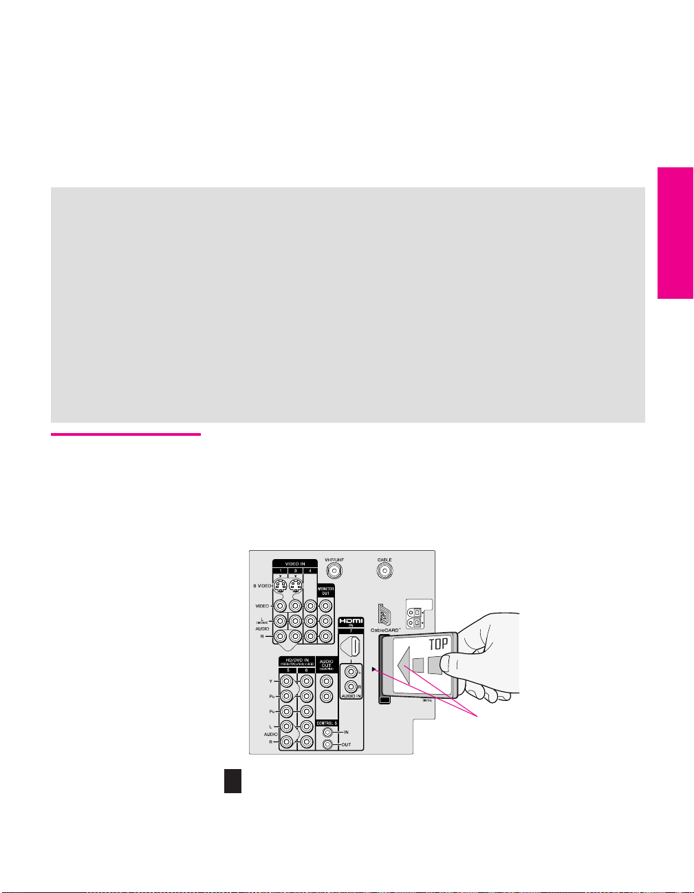
1 Turn off the TV.
2 Insert the CableCARD into the TV’s CableCARD slot.
Top of CableCARD is on same
side as indicator on slot
CAUTION: Inserting the CableCARD incorrectly may result in permanent
!
damage to the card and the TV.
43
Page 45
z
You can also access
information about your
CableCARD in the Applications
Menu (see page 109).
3 Gently push the card into the slot until it locks into place.
4 Turn on the TV. After 1-2 minutes, the CableCARD setup screen is
displayed. This screen includes information your cable TV
company will request before they can activate your service.
5 Follow the displayed instructions: Phone your cable TV
company. A representative will guide you through the activation
process.
6 After your CableCARD is activated, your cable TV company will
download the service information, including the channel list, to
the CableCARD.
After the CableCARD has acquired channels from your cable TV
company, the TV tunes to the lowest available channel.
Removing the CableCARD
In the event you want to cancel your service, contact your cable TV
company.
✍ Once the CableCARD is removed, your TV will no longer decrypt digital
cable TV programming services that require CableCARD.
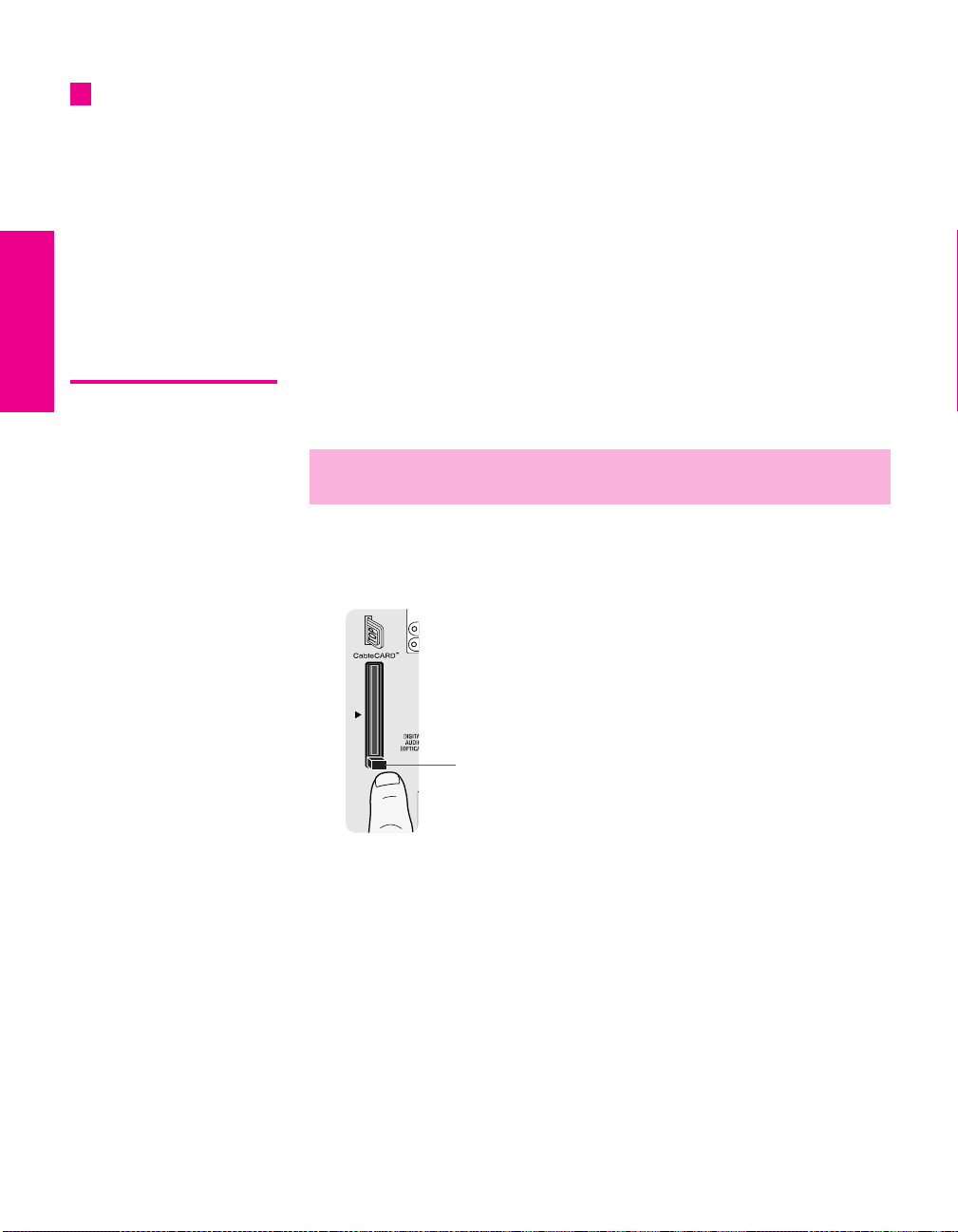
1 Turn off the TV.
2 Push the eject button on the TV’s CableCARD slot to release the
card.
Eject button
3 Pull the CableCARD straight out of the slot to remove it.
To install a different CableCARD, follow the instructions in
“Activating CableCARD Service” on page 43.
SETUP SETUP SETUPSETUP SetupSETUP
44
Page 46

Setting Up the Channel List
After you finish connecting the TV, you need to run the Initial Setup
feature, which automatically creates a list of available analog and
digital channels and lets you correct tilt and vertical correction
settings. The Initial Setup screens appear when you turn on your TV
for the first time after hooking it up.
Using Initial Setup To run Initial Setup
1 Press POWER to turn on the TV.
The Initial Setup screen appears.
2 Using the joystick on the remote control, move the highlight to
the desired language, then press to select that language.
The Tilt Correction screen appears.
z
For more details on using
Tilt Correction and Vertical
Correction, see pages 105-
106.
3 Move the joystick B b to correct any tilt of the picture. You can
choose a correction between +7 and -7.
When finished, press . The Vertical Correction screen appears.
4 Move the joystick V v to make a vertical correction to the picture.
You can choose a correction between +5 and -5. When finished,
press .
z
To exit the Tilt Correction
and Vertical Correction screens,
press the MENU button.
z
If you are using a
CableCARD, Auto Program is
disabled for the CABLE input.
5 The next screen instructs you to connect your cable/antenna.
Check that you’ve connected your signal source correctly.
To start Auto Program, move the joystick to highlight
press .
Auto Program automatically creates a list of receivable analog
and digital channels. Auto Program may take 50 minutes or more
to complete. A progress bar is displayed while the channel list is
being created.
SETUP Setup SETUPSETUP SETUPSETUP
Ye s and then
When the channel list is completed, the lowest numbered channel
is displayed.
To run Auto Program at a later time
❑
Use the Auto Program feature as described on page 100.
To add individual digital channels
Use the Digital Channel feature as described on page 100.
To reset the TV to factory settings
1 Press POWER to turn on the TV.
2 Hold down RESET on the remote control.
3 Press TV POWER on the TV. (The TV will turn itself off, then back
on.)
4 Release RESET.
45
Page 47

Page 48

Using the Remote Control
Overview
This chapter describes how to set up, program, and use the TV’s
remote control.
Topi c Page
Inserting Batteries 47
Button Descriptions
Outside Panel
Inside Panel
Programming the Remote Control 51
Inserting Batteries
1 Remove the battery cover from the remote control.
2 Insert two size AA (R6) batteries (supplied) by matching the e
and E terminals on the batteries to the diagram inside the battery
compartment.
3 Replace the battery cover.
48
50
1
2
✍ Remove the batteries to avoid damage from possible battery leakage
whenever you anticipate that the remote control will not be used for an
extended period.
Handle the remote control with care.
Avoid dropping it, getting it wet, placing it in direct sunlight, near a heater,
or where the humidity is high.
47
Page 49

Button Descriptions
Outside Panel
SETUP SETUP SETUPSETUP SETUPRemote Control
1
2
3
4
5
6
7
8
9
q;
qa
qs
qd
qf
qg
MUTING
SLEEP
i.LINK
TV/VIDEO PIC MODE
SCREEN MODE
VOL
M
MODE
RESET
FAVORITES GUIDE
CODE SET
FREEZE EXIT
SAT/CABLE
SAT/CABLE
ANT
FLIP OPEN
INDEX
MENU
E
M
O
R
Y
DRC
TV
RM-Y201
FUNCTION
K
C
I
T
S
POWER
TV
ENTER
TWIN VIEW
CH
PALETTE
DISPLAY
JUMP
Button Description
1 MUTING Press to mute the sound. Press again or press VOL+ to
qh
restore the sound.
2 SLEEP Press repeatedly until the TV displays the time in
qj
minutes (15, 30, 45, 60, or 90) that you want the TV to
remain on before shutting off automatically. To cancel
qk
press until Sleep Off appears. While the Sleep feature is
set, press once to display the remaining time. Also
ql
available in the Applications Menu (page 108).
3 i.LINK Press to display the i.LINK Control Panel. For
information on using the i.LINK Control Panel, see
page 89. Also available in the Applications Menu
(page 108).
4 TV/VIDEO Press repeatedly to cycle through the video equipment
w;
connected to the TV’s video inputs.
5 ANT Press to switch between the sources connected to the
TV’s VHF/UHF and CABLE inputs.
wa
6 Use with 0-9 and ENTER buttons to select digital
channels (for example, 2.1). For details on selecting
ws
wd
7 INDEX Press to display the Scrolling Index. For details, see
wf
wg
8 SCREEN MODE Press repeatedly to step through the Screen Mode
wh
wj
wk
digital channels, see page 54.
page 57.
settings. Also available in the Screen Menu. For
details, see pages 58 and 99.
9 MENU Press to display the Menu. Press again to exit from the
Menu. For details, see page 93.
q; VOL +/- Press to adjust the volume.
qa Move the joystick
V v B b to move the on-screen
cursor. To select an item, press the center of the
joystick ( ).
qs DRC MODE Press repeatedly to cycle through the available high-
resolution picture modes: Interlaced, Progressive,
CineMotion. Also available in the Video Menu. For
details, see “Selecting Video Options” on pages 94-95.
qd RESET Press to reset the settings to the factory defaults. See
pages 96 and 98. Also used to clear Favorite Channels
(see page 63).
qf FAVORITE S Press to display the Favorite Channels list. For details,
see page 63.
48
Page 50

Button Description
qg CODE SET Press to program the remote control to operate non-
Sony video equipment. For details, see “Programming
the Remote Control” on page 51.
qh POWER
Buttons
qj FUNCTION
Buttons
qk PIC MODE Press repeatedly to cycle through the available video
ql 0 - 9
ENTER
w; TWIN VIEW Press to turn on and off Twin View. For details, see
wa CH +/- Press to scan through channels. To scan quickly
ws MEMORY STICK Press to display the Memory Stick Menu. For details,
wd DRC PALETTE Press repeatedly to cycle through the three Custom
wf DISPLAY Press once to display the current channel number,
wg GUIDE Press to display the program guide. For details, see
wh JUMP Press to jump back and forth between two channels.
wj EXIT Press to exit the on-screen Menu or display and return
wk FREEZE Press to freeze the window picture. Press again to
SAT/CABLE: Press to turn on and off the satellite receiver
or cable box.
TV: Press to turn on and off the TV.
The indicator lights up momentarily when pressed to
show which equipment the remote control is
operating:
SAT/CABLE: Press to have the remote control operate the
satellite receiver or cable box.
TV: Press to have the remote control operate the TV.
picture modes: Vivid, Standard, Movie, Pro. Also available
in the Video Menu. For details, see “Selecting Video
Options” on page 94.
Press 0 - 9 to select a channel; the channel changes
after 3 seconds. Press ENTER to change channels
immediately.
pages 60-62.
through channels, press and hold down either CH
button.
see “Using the Memory Stick Viewer” on page 69.
Also available in the Applications Menu (page 108).
DRC Palette options. Also available in the Video
Menu. For details, see “Selecting Video Options” on
pages 94-96.
current time, and program information banner. Press
again to turn Display off.
page 55.
The TV alternates between the current channel and the
last channel that was selected.
to normal viewing.
restore the picture. For details see page 65.
SETUP SETUP SETUPRemote Control SETUPSETUP
49
Page 51

Inside Panel To access the inside panel, open the outside cover as shown.
wh
wj
wk
wl
ed
eg
ef
ea
e;
es
wg
✍ Opening the outside cover automatically switches the remote control to
operate your VCR or DVD player, depending on the position of the A/V slide
switch. For details, see page 51.
VCR and DVD buttons require that you first program the remote (page 51),
if the VCR and DVD player are not Sony brand.
MUTING
SLEEP
SAT/CABLE
POW
ER
FUNC
TION
SAT/CABLE
CODE SET
MUTING
SYSTEM
OFF
MTS/SAP
DISC MENU
SCREEN MODE
TV
TV/VIDEO PIC MODE
ANT
MP
ENTER
INDEX
N MODE
CREE
S
TW
IN
VIEW
MENU
VOL
CH
M
E
M
K
C
O
I
R
T
Y
S
MODE
PALETTE
DRC
RESET
DISPLAY
FAVORITES GUIDE
FREEZE
JUMP
EXIT
TV
R
M
-Y
20
1
POWER
SAT/CABLE
SLEEP
TV/VCR/DVD
VCR/DVD
i.LINK
SELECT
MENU
INDEX
TWIN VIEW
Button Description
SYSTEM OFF Press to turn off all Sony brand audio/video equipment
wg
at once. (May not function with older Sony equipment.)
wh
Transport
Buttons
m Rewind
N Play
z Record (press together with N)
✍ To record with i.LINK devices, press only z.
x Stop
M Fast forward
X Pause
MTS/SAP Press repeatedly to cycle through the Multi-channel TV
wj
V v B b
wk
DISC MENU Press to display the DVD Menu.
wl
TV/VCR/DVD Press to change to the VHF/UHF output of the VCR (or
e;
VCR/DVD Press to turn on and off the VCR or DVD player.
ea
i.LINK
es
AV1/2/3/DVD
Slide Switch
ed
SELECT Press to select an item in the VCR or DVD player’s
ef
MENU Press to display the DVD player setup Menu.
eg
Sound (MTS) options: Stereo, Auto SAP (Second Audio
Program), and Mono. Also available in the Audio Menu.
For details, see “Using the Audio Menu” on page 97.
Press Vv B b to move the VCR or DVD player ’s onscreen cursor.
DVD/VCR combination unit).
Use the A/V slide switch to control connected video or
i.LINK equipment. You can program one video source
for each switch position. i.LINK-connected devices are
by default set to AV 1. For details, see “Programming the
Remote Control” on page 51.
Press repeatedly to step through the Audio Effect
options. Also available in the Audio Menu. For details,
see page 97.
Menu.
SETUP SETUP SETUPSETUP SETUPRemote Control
50
Page 52

Programming the Remote Control
2
MUTING
SLEEP
TV/VCR/DVD
SYSTEM
OFF
MTS/SAP
SELECT
DISC MENU
INDEX
SCREEN MODE
MUTING
SLEEP
SAT/CABLE
i.LINK
TV/VIDEO PIC MODE
SAT/CABLE
SAT/CABLE
FUNCTION
ANT
VCR/DVD
MENU
TWIN VIEW
TV
POWER
POWER
i.LINK
The remote control is preset to operate Sony brand video equipment.
Sony Equipment Switch Position on
Remote Control
i.LINK i.LINK/AV1 901
8 mm VCR AV2 302
VHS VCR AV3 301
DVD player DVD 751
Programmable Code
Number
If you have video equipment other than Sony brand that you want to
control with the TV’s remote control, use the following procedure to
program the remote control.
✍ The equipment must have infrared (IR) remote capability in order to be used
with the remote control.
1 Turn to the list of “Manufacturer’s Codes” on page 52, and find
the three-digit code number for the manufacturer of your
equipment. (If more than one code number is listed, use the
number listed first.)
2 Open the remote control and set the A/V slide switch to i.LINK/AV1,
, AV3, or DVD. Then close the remote control.
AV2
✍ If the device that you wish to program is connected through i.LINK, you
must set the slide switch to AV1.
3 Press CODE SET.
4 Enter the three-digit manufacturer’s code number.
4
5 Press ENTER.
SETUP SETUP SETUPRemote Control SETUPSETUP
3
SCREEN MODE
VOL
MODE
RESET
CODE SET
FLIP OPEN
INDEX
MENU
M
E
M
S
O
R
Y
DRC
FAVORITES GUIDE
FREEZE EXIT
TV
RM-Y201
C
I
T
ENTER
TWIN VIEW
K
PALETTE
DISPLAY
JUMP
5
✍ You must do step 5 within 10 seconds of step 4, or you must redo
steps 3 through 5.
6 To check if the code number works, aim the TV’s remote control
CH
at the equipment and press the
with that equipment. If it responds, you are done. If not, try using
another code listed for that manufacturer.
Notes
If more than one code number is listed, try entering them one by
❑
one until you come to the correct code for your equipment.
❑ If you enter a new code number, the code number you previously
entered at that setting is erased.
❑ In some cases, you may not be able to operate your equipment
with the supplied remote control. In such cases, use the
equipment’s own remote control unit.
❑ Whenever you remove the batteries to replace them, the code
numbers may revert to the factory setting and must be reset.
POWER button that corresponds
51
Page 53

Manufacturer’s Codes
VCRs
Manufacturer Code
Sony 301, 302, 303
Admiral
(M. Ward)
Aiwa 338, 344
Audio Dynamic 314, 337
Broksonic 319, 317
Canon 309, 308
Citizen 332
Craig 302, 332
Criterion 315
Curtis Mathes 304, 338, 309
Daewoo 341, 312, 309
DBX 314, 336, 337
Dimensia 304
Emerson 319, 320, 316,
Fisher 330, 335
Funai 338
General Electric 329, 304, 309
Go Video 322, 339, 340
Goldstar 332
Hitachi 306, 304, 305, 338
Instant Replay 309, 308
JC Penney 309, 305, 304,
JVC 314, 336, 337,
Kenwood 314, 336, 332, 337
LXI (Sears) 332, 305, 330,
Magnavox 308, 309, 310
Marantz 314, 336, 337
Marta 332
Memorex 309, 335
Minolta 305, 304
Mitsubishi/
MGA
Multitech 325, 338, 321
NEC 314, 336, 337
Olympic 309, 308
Optimus 327
Orion 317
Panasonic 308, 309, 306, 307
Pentax 305, 304
Philco 308, 309
Philips 308, 309, 310
Pioneer 308
SETUP SETUP SETUPSETUP SETUPRemote Control
Quasar 308, 309, 306
RCA/
PROSCAN
327
317, 318, 341
330, 314, 336, 337
345, 346, 347
335, 338
323, 324, 325, 326
304, 305, 308,
309, 311, 312,
313, 310, 329
Manufacturer Code
Realistic 309, 330, 328,
Sansui 314
Samsung 322, 313, 321
Sanyo 330, 335
Scott 312, 313, 321,
Sharp 327, 328
Signature 2000
(M. Ward)
SV2000 338
Sylvania 308, 309, 338, 310
Symphonic 338
Ta sh i ro 3 32
Tatung 314, 336, 337
Teac 314, 336, 338, 337
Technics 309, 308
Toshiba 312, 311
Wards 327, 328, 335,
Yamaha 314, 330, 336, 337
Zenith 331
335, 324, 338
335, 323, 324,
325, 326
338, 327
331, 332
Laserdisc Players
Manufacturer Code
Sony 701
Panasonic 704, 710
Pioneer 702
DVD/VCR Combination Units
Manufacturer Code
Sony 601
Broksonic 605
JVC 604
Panasonic 609
Samsung 603
To sh i ba 60 2
i.LINK Controls
Function Code
Rewind, Play,
Fast-forward,
Record, Stop,
Pause
901
DVD Players
Manufacturer Code
Sony 751
Apex 762
General Electric 755
Hitachi 758
JVC 756
Magnavox 757
Mitsubishi 761
Oritron 759
Panasonic 753
Philips 757
Pioneer 752
RCA/Proscan 755
Samsung 758
To sh i ba 7 5 4
Zenith 760
Cable Boxes
Manufacturer Code
Sony 230
Hamlin/Regal 222, 223, 224,
225, 226
Jerrold/G. I./
Motorola
Oak 227, 228, 229
Panasonic 219, 220, 221
Pioneer 214, 215
Scientific Atlanta 209, 210, 211
Tocom 2 16 , 2 1 7
Zenith 212, 213
201, 202, 203,
204, 205, 206,
207, 208, 218
Satellite Receivers
Manufacturer Code
Sony 801
Dish Network 810
Echostar 810
General Electric 802
Hitachi 805
Hughes 804
Mitsubishi 809
Panasonic 803
RCA/
PROSCAN
Toshiba 806, 807
802, 808
52
Page 54

Using the Features
Overview
This chapter describes how to use the features of your TV.
Topi c Page
Watching TV 54
Using the Program Guide 55
Using the Scrolling Index 57
Using Screen Mode 58
Using Twin View 60
Using Favorite Channels 63
Using the Freeze Function 65
Using Other Equipment with Your TV Remote Control 66
53
Page 55

Watching TV
z
For a complete list of all
the functions of the remote
control, see pages 47-52.
To Do This ... Do This ...
Activate the remote control to
operate the TV
Turn on/off the TV Press TV POWER
Tune directly to a channel To tune to analog channels, press 0-9 and
Press TV FUNCTION
then ENTER.
For digital subchannels, press 0-9, ,
press 0-9 again, and then ENTER.
For example, to select subchannel 21.13,
press 2+1++1+3, and then press ENTER.
✍ You can also select channels using the
program guide. See pages 55 for
details.
Adjust the volume Press VOL +/-
Mute the sound Press MUTING (press again to unmute)
Alternate back and forth
between two channels
Display the current channel
number (and other information)
Switch the TV’s input to the
VCR, DVD player, or other
connected equipment
Change video and audio
options, customize the TV’s
setup, set parental controls, and
more
Switch
the TV’s input between
sources connected to the TV’s
VHF/UHF and CABLE inputs
Press JUMP
The TV alternates between the current
channel and the last channel tuned.
Press DISPLAY once to display the channel
number, current time, and channel label
(if set). Press DISPLAY again to turn Display
off.
Press TV/VIDEO repeatedly to cycle through
the video equipment connected to the
TV’s video inputs.
Press MENU to display the Menu. For
details, see “Using the Menus” on
page 93.
Press ANT to alternate between sources
connected to the TV’s VHF/UHF and
CABLE inputs.
SETUP SETUP SETUPFeatures SETUPSETUP
54
Page 56

Using the Program Guide
z
The program guide is not
available while using multipicture
functions (Twin View, Freeze,
Scrolling Index, i.LINK, Memory
Stick, or Favorite Channels).
GUIDE
Program title and
description, program
duration, time
remaining, rating
information, closed-
caption availability, etc.
Selectable channel list
The program guide lets you review program information and select
both analog and digital channels.
✍ The Program Guide cannot be displayed when the TV is tuned to one of the
video inputs or if the Channel Fix option is set to anything other than Off
(see page 100).
To display the program guide:
Press GUIDE on the TV’s remote control. The program guide appears,
with the currently selected program showing in the background.
Channel number, call
letters, etc.
✍ Program information in the guide is provided by the broadcasters. As a
result, it may sometimes include only the channel number, without a
program title or description.
SETUP SETUP SETUPSETUP SETUPFeatures
To Do This ... Do This ...
Scroll through the channel list
Select the currently displayed
channel and exit the guide
Display additional options Move the joystick b. See “Using
Exit the Guide (without
changing channels)
Move the joystick
Press .
Additional Program Guide Options” on
page 56.
Press GUIDE
V v
55
Page 57

Using Additional Program Guide Options
Move the joystick b while in the program guide’s channel list to
display the following options, which allow you to customize the
settings of the program on the currently tuned channel.
Option Description
Alternate Video
(when
available)
Alternate Audio
(when
available)
Each program has a main video stream (the video that you
see when the channel is first tuned), and may have
alternate video streams. This option allows you to switch
among these alternate video streams.
Each program has a main audio stream (the audio that you
hear when the channel is first tuned) and may have
alternate audio streams. This option allows you to switch
among these alternate audio streams (e.g., for different
languages).
SETUP SETUP SETUPFeatures SETUPSETUP
56
Page 58

Using the Scrolling Index
The Scrolling Index lets you select programs from a series of preview
windows that scroll along the right side of the screen.
1 Press INDEX.
The Scrolling Index appears, with the currently selected program
in the main (left) window, and four scrolling video pictures in the
right.
INDEX
As each picture on the right scrolls to the live preview window, it
changes briefly from a frozen video picture to a live video. The
right side continues to scroll through the entire channel list.
2 To change the direction of the scrolling, move the joystick V or v.
3 To change the speed of the scrolling, move and hold the joystick
V or v.
4 To change a frozen video picture to a live video, move the
joystick V or v to highlight the picture, then press .
5 To move the live video (from step 4 ) from the right to the main
(left) window of the Scrolling Index, press again.
SETUP SETUP SETUPSETUP SETUPFeatures
Live preview
window
To exit the Scrolling Index
❑
Press INDEX.
Factors Affecting Scrolling Index
❑ Scrolling Index does not function if you use a cable box to view all channels.
❑ Scrolling Index does not function if you are using CableCARD (see page 43).
❑ Scrolling Index does not function if parental controls are set (see page 102).
❑ Digital sources, as well as any sources connected to the VIDEO 5, VIDEO 6, VIDEO 7
inputs, display in the left window, but not in the right windows.
57
Page 59

Using Screen Mode
The Screen Mode feature lets you change the picture size for both
z
You can also access the Screen
Mode settings in the Screen Menu.
For details, see page 99.
Using Screen Mode with Standard Definition (480i/480p) Sources
Example Description
‘
SCREEN MODE
Wide Zoom
m
SCREEN MODE
Normal
m
SCREEN MODE
standard-definition (480i/480p) and high-definition (720p/1080i)
sources.
❑ Press SCREEN MODE repeatedly to toggle through the following
Screen Mode settings.
Wide Zoom enlarges the center portion of the
picture proportionately. The left and right
edges of the picture are stretched to fill the
16:9 screen.
Normal displays the 4:3 picture in its original
size. Bars are shown to fill the 16:9 screen.
Full stretches the 4:3 picture horizontally, to fill
the 16:9 screen.
Full
m
SCREEN MODE
Zoom enlarges the 4:3 picture proportionately
to fill the 16:9 screen. Some clipping may
occur. Zoom is useful for watching Letterbox
movies.
Zoom
When you change channels or inputs, the Screen Mode settings revert
to the
4:3 Default setting in the Screen Menu. To retain the current
Screen Mode setting as channels and inputs are changed, set
to
Off. For details, see page 99.
4:3 Default
SETUP SETUP SETUPFeatures SETUPSETUP
58
Page 60
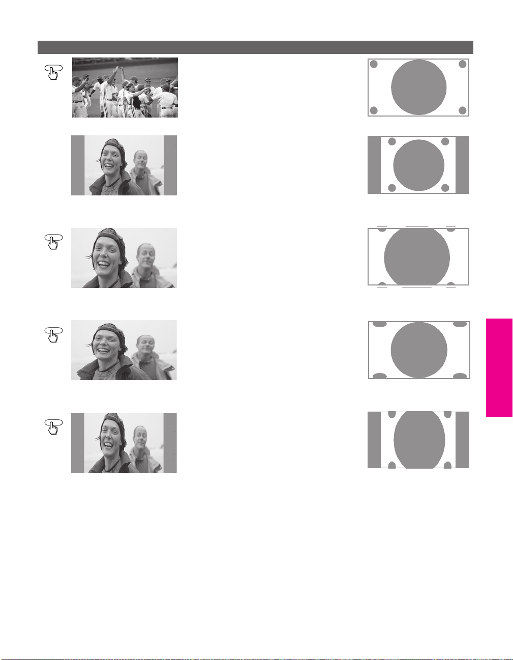
Using Screen Mode with High-Definition (720p/1080i) Sources
Example Description
SCREEN MODE
Full (native 16:9)
Full (upconverted 4:3)
m
SCREEN MODE
Zoom
m
SCREEN MODE
Full displays the picture at its original size.
If the source is a 16:9 high-definition
(720p/1080i) signal, the picture fills the
screen.
If the source is a 4:3 standard-definition
signal that has been upconverted, bars are
shown to fill the 16:9 screen.
Zoom enlarges the picture proportionately,
both vertically and horizontally. Some
clipping may occur.
Horizontal Expand stretches the picture
horizontally. Some clipping may occur.
SETUP SETUP SETUPSETUP SETUPFeatures
SCREEN MODE
Horizontal Expand
m
Vertical Expand stretches the picture
vertically. Some clipping may occur.
Vertical Expand
59
Page 61

Using Twin View
Twin View lets you see two pictures from two sources — from an
antenna, VCR, DVD, etc. — on the screen at the same time. You hear
the sound from only one of the sources at a time, but you can choose
which source’s sound is selected. You can also change the relative size
of each of the pictures.
Displaying Twin Pictures
1 Tune the TV to a working channel.
2 Press .
A second picture appears. The active picture is highlighted.
,
TWIN VIEW
,
To cancel Twin View and watch the active picture
Press or .
❑
Factors Affecting Twin View
❑ If you use a cable box to view all channels, the same channel appears in both windows of
Twin View because the cable box unscrambles only one channel at a time.
❑ If you use a cable box, you can view the cable box output in one Twin View window and
view a different source (such as a VCR or DVD player) in the second window by using the
TV/VIDEO button. For details, see “Connecting Optional Equipment” on page 22.
❑ Digital sources, as well as any sources connected to the VIDEO 5, VIDEO 6, VIDEO 7
inputs, display in the left window, but not in the right window.
❑ If you are viewing a 4:3 source and a 16:9 enhanced source (such as a DVD) side by side in
Twin View, the 4:3 source appears larger.
❑ Twin View does not display channels that are blocked by parental settings (see page 102).
SETUP SETUP SETUPFeatures SETUPSETUP
60
Page 62

Activating the Picture
To Do This ... Do This ...
You can use the B and b buttons to activate the left and right pictures
while using Twin View.
To activate the picture in
the right window
Move the joystick b.
SETUP SETUP SETUPSETUP SETUPFeatures
v
To activate the picture in
the left window
v
Move the joystick B.
Functions Available in the Active (Highlighted) Window
To Do This ... Do This ...
Tune to a channel To tune to analog channels, press 0-9 and
then ENTER.
For digital subchannels, press 0-9, ,
press 0-9 again, and then ENTER.
For example, to select subchannel 21.13,
press 2+1++1+3, and then press ENTER.
Adjust the volume Press VOL +/-
Mute the sound Press MUTING (press again to unmute)
Switch
the TV’s input between
sources connected to the TV’s
VHF/UHF and CABLE inputs
Switch
the TV’s input between
sources connected to the TV’s
A/V inputs
Change the picture size Move the joystick V or v. (For details, see
Press ANT
Press TV/VIDEO
“Changing the Picture Size” on page 62.)
61
Page 63

Changing the Picture Size
To Do This ... Do This ...
Enlarge the active picture
The zoom feature lets you vary the relative size of the left and right
pictures.
v
Move the joystick V.
Make the active picture
smaller
Move the joystick v.
When you adjust the picture sizes, the TV
memorizes the change. The next time you use the
Twin View function, the memorized sizes appear.
v
SETUP SETUP SETUPFeatures SETUPSETUP
62
Page 64

Using Favorite Channels
Using the Channel Menu
MENU
z
For details on using the
Channel Menu, see page 100.
The Favorite Channels feature lets you select programs from a list of
up to 16 favorite channels that you specify. You can create a list using
the Favorite Channel option in the Channel Menu, or by using the
Add to Favorites feature in the Favorite Channels guide.
1 Press MENU to display the Menu.
2 Move the joystick V or v to highlight the Channel icon and press
.
3 Press to select Favorite Channels.
4 Use the 0-9 and ENTER buttons to enter the channel number that
you want to assign to the Favorite Channel number. A preview of
the highlighted channel appears in the upper right of the screen.
✍ Digital channels do not display in the preview window.
Press to select that channel as a Favorite Channel.
✍ To enter digital channel numbers in step 4, use the 0-9, , and ENTER
buttons.
5 To add more channels to your favorites list, repeat step 4.
To clear a Favorite Channel, move the joystick V or v to highlight
the channel you want to clear. Press and then press
RESET.
SETUP SETUP SETUPSETUP SETUPFeatures
6 Press MENU to exit the Menu.
63
Page 65

Using the Favorite Channels Guide
FAVORITES
1 Press FAVORITES. The Favorite Channels list appears.
Preview of
highlighted
Favorite
Channel
Favorite
Channels
2 Move the joystick V or v to highlight the channel you want to
watch.
A preview of the highlighted Favorite Channel appears.
✍ Digital channels do not display in the preview window.
To add the current channel to the list of Favorite Channels,
highlight
Add to Favorites and press .
To change your Favorite Channels list, highlight
press .
3 Press to select the channel you want to watch.
Edit Favorites and
SETUP SETUP SETUPFeatures SETUPSETUP
64
Page 66

Using the Freeze Function
FREEZE
The FREEZE button allows you to temporarily capture a program’s
picture. You can use this feature to write down information such as
phone numbers, recipes, etc.
✍ The Freeze feature is not available while using Twin View.
1 When the program information you want to capture is displayed,
press
FREEZE.
2 The TV switches to Twin View mode and displays the “frozen”
picture on the right, while the current program continues on the
left.
Current
program
in progress
Call 555-1234
3 To cancel and return to normal viewing, press FREEZE (or just tune
to another channel).
Frozen
picture
SETUP SETUP SETUPSETUP SETUPFeatures
65
Page 67

Using Other Equipment with Your TV Remote Control
All Equipment
To Do This ... Do This ...
Switch the TV’s input to the
VCR, DVD player, or other
connected equipment
Set up the TV remote control to
operate non-Sony equipment
Operating a VCR
To Do This ... Press
Activate the remote control
to operate the VCR
Change channels CH +/-
Record N and z simultaneously
Play N
Stop x
Fast forward M
Rewind the tape m
Pause X
Search the picture forward
or backward
Change input mode TV/VCR
Press TV/VIDEO repeatedly to cycle
through the video equipment connected
to the TV’s video inputs.
You must program the remote control the
first time you use it. See “Programming
the Remote Control” on pages 51 to 52.
Open the outside cover, as shown on page 50.
Then set the A/V slide switch to the position
you programmed for the VCR.
M or m during playback
(release to resume normal playback)
Operating a Satellite Receiver
SETUP SETUP SETUPFeatures SETUPSETUP
66
To Do This ... Press
Activate the remote control
to operate the satellite
receiver
Tur n o n/ o f f SAT/CABLE POWER
Select a channel 0-9, ENTER
Change channels CH +/-
Back to previous channel JUMP
Display channel number DISPLAY
Display SAT Guide GUIDE
Display SAT Menu MENU
Move highlight (cursor) Move the joystick
Select item
SAT/CABLE FUNCTION
V v B b
Page 68

Operating a Cable Box
To Do This ... Press
Activate the remote control
to operate the cable box
Tur n o n/ o f f SAT/CABLE POWER
Select a channel 0-9, ENTER
Change channels CH +/-
Back to previous channel JUMP
SAT/CABLE FUNCTION
SETUP SETUP SETUPSETUP SETUPFeatures
Operating a DVD Player
To Do This ... Press
Activate the remote control
to operate the DVD
Play N
Stop x
Pause X
Step through different
tracks of the disc
Step through different
chapters of a video disc
Display the DVD player
Menu (Setup)
Display the DVD Menu DISC MENU
Move highlight (cursor)
Select item
Open the outside cover, as shown on page 50.
Then set the A/V slide switch to the position
you programmed for the DVD player.
M to step forward or m to step backward
CH+ to step forward or CH- to step backward
MENU (inside panel)
V v B b
SELECT
67
Page 69

Operating a DVD/VCR Combination Unit
To Do This ... Press
Activate the remote control
to operate the DVD/VCR
Tur n o n/ o f f VCR/DVD (power)
Switch between the DVD
player and VCR
Display the DVD menu MENU
Play N
Stop x
Pause X
Search the picture forward
or backward
Move highlight (cursor)
and select (DVD)
Record (VCR) N and z simultaneously
Change channels (VCR) CH +/- or 0-9, ENTER (using tuner)
Adjust tracking (VCR) CH +/- (during tape playback)
Open the outside cover, as shown on page 50.
Then set the A/V slide switch to the position
you programmed for the DVD or VCR.
TV/VCR/DVD
M or m during playback
V v B b
SELECT
SETUP SETUP SETUPFeatures SETUPSETUP
68
Page 70

Using the Memory Stick Viewer
About Memory Stick
Memory Stick (sold separately) is a compact, portable, and versatile
Integrated Circuit recording medium with a data capacity that makes
it perfect for portable applications, such as digital photography.
Memory Stick is specially designed for sharing digital data among
Memory Stick compatible products such as digital cameras and
digital video cameras. Because it is removable, Memory Stick can also
be used for external data storage.
The Memory Stick Viewer on your TV allows you to view files that
are stored on Memory Stick media. You can view:
❑ Digital photos (JPEG files)
❑ Movies (MPEG1 files)
You can also play slide show background music using MP3 files (or
m3u playlists) stored on your Memory Stick.
For more information about handling Memory Stick media, see
“Notes on Using Memory Stick Media” on page 83.
Features With the Memory Stick Viewer, you can:
❑ View photo (JPEG) and movie (MPEG1) files in a thumbnail
index or Slide Show
❑ Set customized Slide Show options, including transitions and
background audio
❑ Pan, zoom, and rotate photos
❑ Mark photos and set quantities of prints to be output when the
Memory Stick is inserted into your photo printer (not supplied)
❑ Lock (protect) or delete files on the Memory Stick
69
Page 71

Memory Stick Compatibility
This television is compatible with the following Sony brand Memory
Stick media types:
❑ Memory Stick Media
❑ Memory Stick Duo and PRO Duo Media
✍ The Memory Stick slot on your TV has been designed to accommodate
standard and compact versions of Memory Stick. It is not necessary to use
an adapter for Memory Stick Duo and Memory Stick PRO Duo. If you use an
adapter it may damage the adapter and Memory Stick slot.
❑ Memory Stick Media with Memory Select Function
❑ Memory Stick PRO Media
About Memory Stick PRO Media
Memory Stick PRO media features vary by and are dependent upon
the design of host hardware devices. Memory Stick PRO in this
television has been tested to support up to 1 GB media capacity and
does not support high-speed transfer, MagicGate copyright
protection technology, or access control security features.
Memory Stick Functionality
SETUP Memory Stick SETUPFeatures SETUPSETUP
Sony cannot guarantee or assure the Memory Stick functionality on
this television in the following cases:
❑ You are using non-Sony brand Memory Stick media.
❑ You are using video or audio clips that have been processed on a
computer.
❑ You are using files that were obtained from the Internet or from a
printed film processing center.
❑ The Memory Stick has been formatted on a personal computer.
Sony recommends that you back up all data stored on Memory Stick
media to avoid potential data loss. In the above two cases, in order to
avoid potential data corruption that may occur, be sure to back up
data prior to use with the TV’s Memory Stick Viewer. Sony cannot
accept responsibility in the event that data recorded to Memory Stick
media is lost or damaged. For certain non-Sony brand Memory Stick
media, you can view images, but you cannot rotate, delete or
protect/unprotect images on the television. An error message will
occur if you attempt any of these operations. This is a result of the
unique file directory structure on these particular flash memory
media and is not a malfunction of the television.
70
Page 72

File Compatibility The Memory Stick Viewer is compatible with JPEG images taken with
*
Sony digital still cameras and MPEG1
digital cameras and camcorders. In order to be viewable in the
Memory Stick Viewer, the files must have the following file name
extensions:
File Type Supported File Name Extensions
JPEG .jpg
.jpeg
MPEG1 .mpg
.mpeg
movies taken with Sony
SETUP SETUP SETUPSETUP Memory StickFeatures
Trademark Information
Memory Stick, Memory Stick Duo, Memory Stick PRO, Memory Stick
PRO Duo, and MagicGate are trademarks of Sony Corporation.
*Some variations of MPEG1 movies may not play back correctly.
71
Page 73

Inserting and Removing a Memory Stick
Inserting a Memory Stick
I.LINK
S VIDEO
VIDEO 2 INPUT
VIDEO
✍ The Memory Stick slot on your TV has been designed to accommodate
standard and compact versions of Memory Stick. It is not necessary to use
an adapter for Memory Stick Duo and Memory Stick PRO Duo. If you use an
adapter it may damage the adapter and Memory Stick slot.
1 Locate the Memory Stick slot (see page 14) and insert the
Memory Stick into the Memory Stick slot as illustrated below.
When inserted properly, it should slide in with little resistance
and click into place.
PRO
L(MONO) -– AUDIO – R
i.LINK
MENU
STD/DUO
PRO
TV/VIDEO
VOLUME
+
CHANNEL
_
STD/DUO
i.LINK
STAND BY
TIMER/
STAND BY
POWER
✍ Be sure to insert the Memory Stick in the correct direction. If the Memory
Stick is forced in the wrong way, it may become damaged.
Insert only Memory Stick media into the Memory Stick slot. Attempting to
insert other objects into the slot may damage the TV.
To remove the Memory Stick, see “Removing a Memory Stick” on
page 73.
SETUP Memory Stick SETUPFeatures SETUPSETUP
72
Page 74

Removing a Memory Stick
To remove a Memory Stick
1 Check that the Memory Stick indicator is off. (When the light is
on, this indicates that the TV is reading data from the Memory
Stick.)
✍ Removing the Memory Stick while a file is being accessed (when the
Memory Stick LED on the TV’s front panel is lit) may damage the Memory
Stick or its contents.
2 Push the Memory Stick gently into the slot, and then release it.
The Memory Stick media is ejected.
✍ Do not pull out the Memory Stick without first pushing it in; otherwise, the
TV’s locking mechanism may become damaged.
3 Pull the Memory Stick completely out of the slot.
✍ To protect small children from injury from Memory Stick Media, remove all
Memory Stick media from the TV’s Memory Stick slot and store it in a safe
location when it is not in use.
SETUP SETUP SETUPSETUP Memory StickFeatures
73
Page 75

Using the Memory Stick Index
Turn on the TV and insert a Memory Stick that contains the photo or
movie files you want to view. For details, see page 72.
✍ If the Memory Stick Index does not appear, press the MEMORY STICK button
on the remote control.
The Memory Stick Index appears, which displays thumbnail images
of the files stored on the Memory Stick.
Information about the
highlighted photo or movie
Highlighted thumbnail
Thumbnails of photos and
movies
Memory Stick Menu bar
About the Icons on the Thumbnail Images
Indicates the thumbnail is a movie (MPEG1) file instead of a photo
(JPEG) file.
Indicates the thumbnail is locked. Locked files cannot be changed
or deleted. For details, see “Protect” on page 77.
Indicates that the photo is marked to be printed.
Indicates that the photo has an associated voice memo.
SETUP Memory Stick SETUPFeatures SETUPSETUP
74
Page 76

Using the Memory Stick Index
The following describes how to use the Memory Stick Index.
To Do This ... Do This ...
Move the highlight
to a photo, voice
memo ( ), or
movie ( )
thumbnail
Display the
highlighted photo,
voice memo, or
movie file full
screen
Display the next
page of thumbnails
Display the
previous or next
page of thumbnails
Use the Memory
Stick Menu bar to
access additional
options
Move the highlight
from the Memory
Stick Menu bar back
to the thumbnails
Exit Memory Stick
Viewer
Move the joystick
Press . For details, see “Viewing Photos” on
page 76 and “Playing Movies” on page 79.
1 Move the joystick
2 Move the joystick
thumbnails.
1 Move the joystick
2 Move the joystick
3 To go to the previous page, move the joystick
To go to the next page, move the joystick
1 Move the joystick
2 Move the joystick
Contents, or Memory Stick.
3 Move the joystick V or
want to change.
For details on these options, see “Memory Stick
Index Menu Bar Options” on page 81.
1 Move the joystick
2 Move the joystick
displayed thumbnails, or
page of thumbnails.
Press the MEMORY STICK button on the remote
control.
V v B b.
v to select V.
v to display the next page of
v to select V.
B to select .
Y
v to select V.
B or b to select Slide Show,
v to select the option you
B or b to select V.
V to return to the currently
v to display the next
SETUP SETUP SETUPSETUP Memory StickFeatures
V.
v.
75
Page 77

Viewing Photos
Information about
selected photo
Selected photo
Previous/next buttons
Photo Menu bar
When you select a photo from the Memory Stick Index (described on
page 74), it displays as shown below, with the following controls.
✍ JPEGs captured using a digital video camera may appear to display motion
in full screen. This is a result of the way digital video cameras record still
images, and is not a result of a malfunction with the TV.
Photo Controls
z
When the Menu is hidden,
move the joystick
to the previous or next photo.
SETUP Memory Stick SETUPFeatures SETUPSETUP
B or b to go
To Do This ... Do This ...
Display the next or
previous file on the
Memory Stick
Hide the Photo Menu bar,
displaying only the photo
Display the hidden Photo
Menu bar
Play the JPEG voice memo
( files only)
Display the Memory Stick
Index again
Access additional options
in the Photo Menu bar
Exit Memory Stick Viewer Press the MEMORY STICK button on the remote
Highlight the (Previous/Next) button.
Then move the joystick
file, or
b to go to the next file.
With the highlight in the Photo Menu bar, move
the joystick
Move the joystick
Highlight B (Play) and then press . To pause
the voice memo, highlight X (Pause) and then
press .
Highlight Index in the Photo Menu bar and
press .
For details on the Memory Stick Index, see
page 75.
See “Photo Menu Bar Options” on page 77.
control.
v.
B to go to the previous
V.
76
Page 78

Photo Menu Bar Options
z
JPEG files that are protected
are indicated by the Lock
icon.
z
The Print Quantity feature is
also known as DPOF (Digital
Print Order Format).
The Photo Menu bar lets you access additional photo viewing
options.
To access the Photo Menu bar
1 Move the joystick B or b to select Slide Show, View, or File.
2 Press to select the desired option.
Option Description
Index Displays the Memory Stick Index, with the highlight on the
thumbnail of the currently displayed photo. For details, see
“Using the Memory Stick Index” on page 74.
Slide Show Displays the Slide Show Menu. For details, see “Slide Show
Menu Options” on page 81.
View Rotate Allows you to rotate the photo in 90 degree
increments clockwise or counterclockwise. For
details, see “Using Rotate” on page 78.
Zoom/Pan Allows you to magnify and pan across the
photo. For details, see “Using Zoom and Pan”
on page 78.
File Prote ct
Print Quantity Allows you to indicate the number of prints to
Delete Deletes the JPEG file from the Memory
Allows you to the protect the JPEG file from
any changes. When a JPEG file is protected, it
cannot be rotated or deleted. Select On or Off.
make of the specific photo when the Memory
Stick is inserted into a compatible photo
printer (not supplied).
Stick.You cannot delete a JPEG file that has
been protected (or if the Memory Stick is
locked).
SETUP SETUP SETUPSETUP Memory StickFeatures
77
Page 79

Using Zoom and Pan
To Zoom and Pan a photo
1 In the Photo Menu bar, highlight View.
2 Highlight Zoom/Pan and press .
3 Specify the zoom center point by moving the joystick; then press
to set the center.
The Zoom and Pan controls are displayed.
To Do This ... Do This ...
Zoom in (increase magnification)
or out (decrease magnification)
Pan (move the photo left,
right, up, down)
Exit the Zoom/Pan controls Highlight Exit and press .
Exit Memory Stick Viewer Press the MEMORY STICK button on the remote control.
Highlight Zoom and press V to zoom in or v to zoom out.
For help on using Zoom, press .
(You can use Pan only when the photo is magnified using Zoom.)
Highlight Pan and press . Then move the joystick
around the photo.
To stop using Pan, press .
B b V v to pan
Using Rotate To R o t ate a p h oto
1 In the Photo Menu bar, highlight View.
2 Highlight Rotate.
3 To rotate clockwise, highlight Clockwise and press .
The photo is rotated 90 degrees each time you press .
SETUP Memory Stick SETUPFeatures SETUPSETUP
78
To rotate counterclockwise, highlight
Counterclockwise and press .
Page 80

Playing Movies
Information about
selected movie
Selected movie
Enlarge button
Play/pause button
Previous/next buttons
Movie Menu bar
Movie Controls
z
The quality of the movie
when enlarged depends on the
resolution of the MPEG1 file. See
your camera’s instruction manual
for details.
When you select a movie from the Memory Stick Index (described on
page 74), it displays as shown below, with the following controls.
To Do This ... Do This ...
Enlarge the movie
window
Play the movie with the
movie controls displayed
Pause the movie Highlight X (Pause) and then press .
Display the previous or
next file on the Memory
Stick
Hide the Movie Menu
bar, displaying only the
movie
Display the hidden
Movie Menu bar
Access additional options
in the Movie Menu bar
Exit Memory Stick
Viewer
Highlight Enlarge, and then press . To d is p l ay
the movie controls again, press
movie ends, the movie controls are displayed
again.
Highlight
Highlight the (Previous/Next) button.
Then move the joystick
file, or
With the highlight in the Movie Menu bar, move
the joystick
Move the joystick
See “Movie Menu Bar Options” on page 80.
Press the MEMORY STICK button on the remote
control.
B (Play) and then press .
b to go to the next file.
v.
V.
. When the
B to go to the previous
SETUP SETUP SETUPSETUP Memory StickFeatures
79
Page 81

Movie Menu Bar Options
z
MPEG1 files that are
protected are indicated by the
Lock icon.
To access the Movie Menu bar
1 Highlight Index in the Movie Menu bar.
2 Move the joystick B or b to select Index, Slide Show, or File .
3 Select the desired option.
Option Description
Index Displays the Memory Stick Index, with the highlight on the
thumbnail of the currently displayed movie.
Slide Show Displays the Slide Show Menu. For details, see “Slide Show
Menu Options” on page 81.
File Prote ct
Delete Deletes the MPEG1 file from the Memory
Allows you to the protect the MPEG1 file from
any changes. When an MPEG1 file is
protected, it cannot be deleted. Select On or Off.
Stick.You cannot delete an MPEG1 file that has
been protected (or if the Memory Stick is
locked).
SETUP Memory Stick SETUPFeatures SETUPSETUP
80
Page 82

Memory Stick Index Menu Bar Options
Slide Show Menu Options
z
The Slide Show Menu is the
same whether you select it from
the Memory Stick Index
(page 74), Photo (page 76), or
Movie (page 79) Menus.
z
When you select Complete
List, it may take a moment to
display the list of all MP3 files.
z
Some JPEG files may take
longer to display than others,
which may make it seem longer
than the interval you selected for
Slide Advance.
You can also display file
information using the
DISPLAY button on the remote
control.
The Slide Show Menu includes the following options:
Option Description
Start Starts the Slide Show.
Music Allows you to select background audio to play during the
Slide Show.
Off No additional background audio is played
during the Slide Show. Audio that is associated
with the JPEG or MPEG1 files will play.
Play Memory
Stick
Piano (built-in) Plays the MP3 file stored in the TV’s internal
(List of MP3
Files and
Playlists)
Complete
List
Transition
Effect
Slide Advance Allows you to specify when to advance to the next slide.
File
Information
Repeat On Slide Show continuously loops.
Allows you to select an effect to be used when advancing to
the next file in the Slide Show.
Fas t Slide advances after about 3 seconds.
Medium Slide advances after about 6 seconds.
Slow Slide advances after about 12 seconds.
Manual Slide advances only after you move the
Determines whether file information is shown when the file is
displayed full screen. Select On or Off.
Off Slide Show plays once through all files and
Plays all MP3 files on the Memory Stick. The
Piano MP3 file and any MP3 file playlists are
not played.
memory.
Displays a list of all MP3 files and MP3 file
playlists found at the top level (root) of the
Memory Stick. To show additional MP3 files
stored in other folders on the Memory Stick,
select Complete List.
Displays a list of all available MP3 files.
joystick
ends.
SETUP SETUP SETUPSETUP Memory StickFeatures
B or b.
81
Page 83

Contents Menu Options
z
The Rotate function does not
change the file’s modification
date.
The Contents Menu includes the following options:
Option Description
Select Folder Allows you to select different folders to view in the
Memory Stick Viewer.
Digital Camera
Folders
Select a Folder Allows you to access individual folders
File Order Allows you to change the order in which the Memory
Stick files are displayed.
Date Order Displays files in chronological order by
Date Order Reverse Displays files in reverse chronological
Alphabetical Displays files in alphabetical order by
Filte r Allows you to selectively display specific file types
within the selected folder.
Show Photos and
Movies
Show Photos Only Displays only photo (JPEG) files.
Show Movies Only Displays only movie (MPEG1) files.
Show All Print
Marks
Selects all folders within the directories
defined by the DCF rules used by Sony
digital cameras (see page 83). JPEG and
MPEG1 files in those directories are
recognized even if they do not conform
to the DCF file naming rules.
on the Memory Stick.
modification date.
order by modification date.
filename.
Displays all readable files.
Displays all files that are marked for
printing. For details, see “Print
Quantity” on page 77.
Memory Stick Menu
SETUP Memory Stick SETUPFeatures SETUPSETUP
82
The Memory Stick Menu displays the current status of the Memory
Stick, including total capacity, used capacity, and free capacity.
Page 84

Notes on Using Memory Stick Media
About DCF File Names
Most Sony brand digital still and video cameras automatically record
still photo and movie files using DCF compliant directory and file
names.
SETUP SETUP SETUPSETUP Memory StickFeatures
If you selected the
you might want to have your digital camera’s instruction manual
handy in order to check how files and directories are organized for
your specific model of digital camera.
DCF stands for “Design Rules for Camera File Systems,” which are
specifications established by the Japan Electronic Industry
Development Association (JEIDA).
Digital Camera Folders option, as described on page 82,
83
Page 85

Memory Stick Precautions
When using Memory Stick media, follow these precautions:
❑ To avoid permanent damage to still image data, do not turn
off the TV or remove Memory Stick media from the insertion
slot while data is being read (as indicated by the Memory
Stick indicator light being on).
❑ Avoid touching the terminal of Memory Stick media or
bringing it into contact with a metal object.
❑ Do not drop, bend, or submit Memory Stick media to external
shock.
❑ Do not disassemble or modify Memory Stick media.
❑ Avoid getting liquid on Memory Stick media.
❑ Apply labels only within the designated label area.
Label Area
❑ To avoid permanent damage to still image data, do not use or
store Memory Stick media in a location subject to:
❑ High temperature (such as near a heater or inside a hot
car)
❑ High humidity
❑ Direct sunlight
❑ Corrosive substances
❑ Magnetic fields
❑ Excessive dust
❑ Static electricity or electric noise
❑ Electric surges
❑ Store and carry Memory Stick media in its original case to
ensure protection of stored data.
❑ Save a backup of stored data.
SETUP Memory Stick SETUPFeatures SETUPSETUP
84
Page 86

Using i.LINK
About i.LINK
This TV is equipped with i.LINK, which provides a secure digital
interface to other digital home entertainment devices, such as digital
VCRs, digital camcorders, set-top boxes, and other devices that also
are equipped with i.LINK. i.LINK allows for the secure transfer of
copyright-protected digital content between these devices and your
digital television.
i.LINK is a trademark of Sony Corporation and used only to
designate that a product contains an IEEE 1394 connector.
All products with an i.LINK connector may not communicate with
each other.
Using i.LINK Cables
This TV has three S400 i.LINK terminals (one in the front panel, and
two in the back panel). You can use the following i.LINK cables with
this TV:
Sony Model Length
VMC-IL4415 1.5 meters
4-pin i.LINK cable
VMC-IL4435 3.5 meters
✍ Do not use cables other than the ones listed above.
85
Page 87

Connecting i.LINK Devices
✍ Before connecting this unit to i.LINK-compatible equipment, read the
instruction manual of the i.LINK device to be connected.
To connect a digital i.LINK device (using only a digital signal)
1 Using an i.LINK cable (see page 85), connect the device’s i.LINK
jack to either of the TV’s i.LINK jacks.
To connect an i.LINK device that supports an EIA-775A connection
1 Using an i.LINK cable (see page 85), connect the device’s i.LINK
jack to either of the TV’s i.LINK jacks.
2 Using an A/V cable, connect the i.LINK device's A/V output
jacks to the TV's VIDEO 3 A/V input jacks.
✍ Only one i.LINK cable should connect the TV and any given i.LINK device.
TV
i.LINK
cable
Cables are often
color-coded to connectors.
Connect red to red,
white to wh ite.
i.LINK-equipped
Device
i.LINK SETUP SETUPi.LINK i.LINKSETUP
A/V cable (optional)
86
Page 88

Notes on Using This Connection
To Do This ... Do This ...
Set up a digital
i.LINK device
Set up an i.LINK
device that supports
an EIA-775A analog
connection
Notes on Connecting i.LINK Devices
For digital i.LINK devices (devices that require only
the i.LINK connection), no setup is necessary. The TV
automatically recognizes the device as soon as the
connection is made.
1 Connect analog A/V cables to the VIDEO 3 input
(see page 86).
2 Use the i.LINK Control Panel to activate the analog
connection to your i.LINK device (see page 91).
To connect two or more i.LINK devices, use i.LINK cables to connect
them as shown below.
A B C D E
i.LINK i.LINK i.LINK i.LINK
You can connect up to 63 i.LINK devices. However, the maximum
number of cables in any serial route is 16.
SETUP i.LINK i.LINKSETUP SETUPi.LINK
A B C D
i.LINK i.LINK i.LINK i.LINK
E
F G
i.LINK i.LINK
Do not connect i.LINK devices in a way that creates a loop.
i.LINK
A B C
i.LINK i.LINK
Connecting non-compatible devices, such as PCs or PC peripherals,
may result in malfunctions.
87
Page 89

Selecting an i.LINK Device
Before an i.LINK device can be viewed, it must first be selected via
the i.LINK Device List.
i.LINK
1 Connect the i.LINK device that you wish to operate.
✍ For instructions on connecting i.LINK devices, see page 86.
2 Press i.LINK on the remote control.
The TV (DTV), along with all devices connected by i.LINK to the
TV, appear on the Device List.
Devices that are not supported by the TV appear on the Device
List as “Other Device,” but cannot be controlled using the TV's
remote control or on-screen i.LINK Control Panel. For these
devices, use the remote control supplied with the device.
3 Move the joystick V or v to navigate among the i.LINK-connected
devices.
✍ i.LINK devices can be connected to one another and to the TV while the TV
is powered on. The Device List will automatically update to include the
newly-connected device. See page 86 for more information on connecting
i.LINK devices.
4 Press to select the desired device and display the device's
i.LINK Control Panel. Use the i.LINK Control Panel to operate
the selected device. For details, see page 89.
i.LINK SETUP SETUPi.LINK i.LINKSETUP
88
Page 90

Using the i.LINK Control Panel
After you select an i.LINK device using the Device List, the TV
displays the i.LINK Control Panel, which allows you to use the TV's
remote to control the selected i.LINK device.
1 If the i.LINK Control Panel is not already displayed, press i.LINK
on the remote control.
✍ If i.LINK is pressed while the TV is displaying an analog or digital channel
(not the i.LINK device), then the Device List will appear. Select the desired
device from the list and press to display the Control Panel.
2 Move the remote control’s joystick V v B b to navigate through
the options available in the i.LINK Control Panel.
3 Press to select a desired option.
4 Press i.LINK to exit the Control Panel and view the i.LINK device
full-screen.
✍ To exit i.LINK mode, select DTV from the Device List or press CH+/-.
SETUP i.LINK i.LINKSETUP SETUPi.LINK
The DTV window appears only if the
i.LINK Menus were entered while
watching a digital TV channel
The i.LINK Control Panel displays the signal from the TV to the left
(if available), and the signal from the currently selected device to the
right.
89
Page 91
To Do This ... Do This ...
Go to the Device List Move the joystick to highlight Back to Device List and press .
Change the audio being played
from the TV to the current selected
device, and vice versa
Play a recording from the selected
i.LINK camcorder or digital VCR
Fast-forward or rewind a recording
from the selected i.LINK camcorder
or digital VCR
Record from TV to the selected
i.LINK digital VCR
Stop a recording from the selected
i.LINK digital VCR
Turn the selected device power on
and off
Setup the selected device Move the joystick to highlight Setup and press . For more details on
Move the joystick to highlight Swap Audio and press . An icon
appears next to the window that currently has sound.
Move the joystick to highlight and press .
Move the joystick to highlight or and press .
If the (record) button is available, move the joystick to highlight
and press .
Move the joystick to highlight and press .
Move the joystick to highlight Pow er and press .
Setup, see page 91.
Notes About Controlling i.LINK Devices
❑ You can control the functions of the selected i.LINK device by using the equivalent
buttons on the TV's remote control. To program the remote control to operate i.LINK
devices, see “Programming the Remote Control” on page 51.
❑ Some options on the i.LINK Control Panel may not be available, depending on the device
being controlled.
❑ Only i.LINK-equipped digital camcorders and digital VCRs can be controlled directly
through the i.LINK Control Panel.
❑ Not all functions are supported for all i.LINK devices.
❑ If you are using a digital VCR, turn off any Auto LINC functionality of the VCR. For
details, see the digital VCR’s user manual.
i.LINK SETUP SETUPi.LINK i.LINKSETUP
90
Page 92
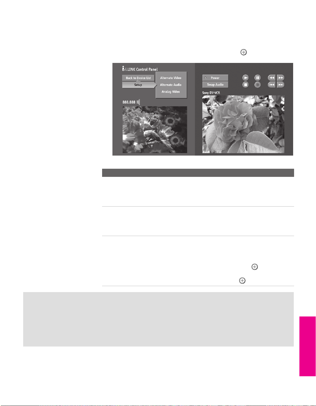
i.LINK Setup
You can use the i.LINK Control Panel to access digital setup options.
To set up the selected device:
Move the joystick to highlight Setup and press .
❑
The following options are displayed:
Option Description
Alternate Video
(when
available)
Alternate Audio
(when
available)
Analog Video The TV is able to accept an analog signal from a selected
Each program has a main video stream (the video that you
see when the channel is first tuned), and may have
alternate video streams. This option allows you to switch
among these alternate video streams.
Each program has a main audio stream (the audio that you
hear when the channel is first tuned). This option allows
you to switch among these alternate audio streams (e.g.,
for different languages).
set-top box. The set-top box must be EIA-775A compliant
and must be connected to the TV’s VIDEO 3 input. To
associate the device with the TV's analog VIDEO 3 input,
move the joystick to Analog Video and press . All EIA-
775A-compliant devices will be shown in the list. Select the
desired device from the list and press .
SETUP i.LINK i.LINKSETUP SETUPi.LINK
Notes on i.LINK
❑ The TV can act as an i.LINK repeater, so that i.LINK signals can be relayed to another
device even when the TV is powered off. To enable this feature, set the
to
On using the Setup Menu as described on page 106.
❑ Parental Control settings apply to the signal from a selected device. For more details, see
page 102.
i.LINK Standby option
91
Page 93

Page 94

Using the Menus
Overview
The Menu gives you access to the following features:
Menu Icon Description Page
z
Press MENU to enter and
exit Menus.
The Video Menu allows you to make adjustments to
your picture settings. It also allows you to customize
the Picture Mode based on the type of program you
are viewing, select Advanced Video options, and
more.
The Audio Menu Offers enhanced audio options such
as listening to second audio programming (SAP) or
customizing the Effect of the sound on your TV.
The Screen Menu allows you to make Screen Mode
adjustments and make changes to the screen’s vertical
center and size.
The Channel Menu allows you to set up a Favorite
Channels list, run the Auto Program function, label
channels, and more.
The Parental Lock Menu lets you control the viewing
of programs based on their ratings.
94
97
99
100
102
The Setup Menu provides options for setting up your
system, including selecting closed caption modes,
labeling video inputs, selecting the language and
color of the on-screen Menus, and more.
The Applications Menu lets you display the Memory
Stick Viewer, the i.LINK Control Panel, set on/off
Timers, access CableCARD and diagnostics
information, and more.
Navigating Through Menus
To Do This ... Do this...
Display the Menu Press MENU
Move through the Menus
Select an option to change Press
Select (confirm) changed setting Press or move the joystick
Exit the Menu Press MENU
Move the joystick
105
108
V v B b
B
93
Page 95

Using the Video Menu
To access the Video Menu, follow these steps:
1. Display Menu 2. Highlight 3. Press to select
MENU
To change settings, move the joystick V v B b.
Press to confirm the selection.
To exit the Menu, press
Selecting Video Options
You can also change the
Mode setting using the
PIC MODE button on the
remote control.
z
You can alter the Video
Menu settings (Picture,
Brightness, Color, etc.) for each
Mode.
MENU.
The Video Menu includes the following options:
Option Description
Mode
Customized
picture
viewing
Picture Adjust to increase picture contrast and deepen the color, or
Brightness Adjust to brighten or darken the picture.
Color Adjust to increase or decrease color intensity.
Hue Adjust to increase or decrease the green tones.
Sharpness Adjust to sharpen or soften the picture.
Color Temp.
White
intensity
adjustment
Vivid Select for enhanced picture contrast and
sharpness.
Standard Select for standard picture settings.
Movie Select to display a softer picture.
Pro Select to display a picture with minimum
enhancements.
To co ntro l how the Mode settings (Vivid, Standard, Movie, Pro) are
applied to each video input, see Mode Memory on page 96.
decrease picture contrast and soften the color.
Cool Select to give the white colors a blue tint.
Neutral Select to give the white colors a neutral tint.
Warm Select to give the white colors a red tint
(NTSC-Standard).
Menus Menus MenusSETUP SETUPSETUP
94
Page 96

You can also change the
e
DRC Mode using the DRC
MODE button on the remote
control.
You can also change the
DRC Palette using the DRC
PALETTE button on the remote
control.
Option Description
ClearEdge VM
Ve lo c i ty
Modulation
Advanced
Video
Sharpens picture definition to give every object a sharp, clean
edge. Select from High, Medium, Low, Off.
Select Program to choose among the Advanced Video options.
DRC Mode Creates a high-resolution picture with 4x
DRC Palette Allows you to customize the level of detail
Menus SETUP MenusSETUP MenusSETUP
density, for high quality sources (i.e., DVD
player, satellite receiver).
Interlaced Recommended for moving
pictures.
Progressive Recommended for still images and
text.
CineMotion Provides an optimized display by
automatically detecting film
content and applying a reverse 3/2
pulldown process. Moving
pictures will appear clearer and
more natural-looking.
(Reality) and smoothness (Clarity). You can
create up to three Custom DRC Palettes.
1 Move the joystick to highlight Custom 1,
Custom 2, or Custom 3 and then press .
The DRC palette appears.
z
For best results, adjust the
Reality by moving the joystick
v
until you are satisfied with th
level of detail. Then adjust the
Clarity by moving the joystick
b
until you have a smooth,
detailed image.
V
B
Custom 1
[25]
Reality
Clarity [ 1]
2 Move the joystick to adjust the position of
the marker ( ). As you move the higher
along the Reality axis, the picture becomes
more detailed. As you move the to the
right along the Clarity axis, the details
become more smoothly integrated with
one another.
3 To save the setting, press .
To return the Custom options to the default
factory settings, press the RESET button.
95
Page 97

Option Description
Advanced
Video
(continued)
To restore the factory default settings for Video settings:
Press RESET on the remote control when in the Video Menu.
❑
Color Axis Allows you to control the emphasis of red
tones.
Default Emphasizes red tones.
Monitor De-emphasizes red tones.
Mode Memory Allows you to control how the Mode settings
(Vivid, Standard, Movie, Pro) are applied to TV
viewing, Memory Stick viewing, i.LINK and
each video input. For details about Mode
settings, see page 94.
Off Set to Off to apply the same Mode
settings to all video inputs.
Changing inputs does not change
the Mode setting.
On Set to On to customize Mode
settings for each video input.
Changing inputs might change the
Mode setting.
Menus Menus MenusSETUP SETUPSETUP
96
Page 98

Using the Audio Menu
To access the Audio Menu, follow these steps:
1. Display Menu 2. Highlight 3. Press to select
MENU
To change settings, move the joystick V v B b.
Press to confirm the selection.
v
Menus SETUP MenusSETUP MenusSETUP
To exit the Menu, press
Selecting Audio Options
You can also change the
Effect using the button
on the inside panel of the
remote control.
MENU.
The Audio Menu includes the following options:
Option Description
Tre bl e Adjust to decrease or increase higher-pitched sounds.
Bass Adjust to decrease or increase lower-pitched sounds.
Balance Adjust to emphasize left or right speaker balance.
Steady Sound Auto Select to stabilize the volume.
Off Select to turn off Steady Sound.
✍ The Steady Sound option is not available (it is grayed out)
if the Effect option is set to TruSurround or Simulated. To
use Steady Sound, set Effect to Off.
Effect TruSurround Select for surround sound (for stereo programs
only).
Simulated Adds a surround-like effect to mono programs.
Off Normal stereo or mono reception.
MTS
Enjoy stereo,
bilingual and
mono programs
Stereo Select for stereo reception when viewing a
program broadcast in stereo.
Auto SAP Select to automatically switch the TV to second
audio programs when a signal is received. (If
no SAP signal is present, the TV remains in
Stereo mode.)
Mono Select for mono reception. (Use to reduce noise
during weak stereo broadcasts.)
✍ MTS is available only with analog programs.
97
Page 99

Option Description
Speaker On Select to turn on the TV speakers.
Off Select to turn off the TV speakers and listen to
the TV's sound only through your external
audio system speakers.
Audio Out
Easy control of
volume
adjustments
To restore the factory default settings for Treble, Bass, and Balance
Press RESET on the remote control when in the Audio Menu.
❑
This option can be set only when the Speaker option is set
to Off.
Variable The TV’s speakers are turned off, but the
volume output from your audio system can
still be controlled by the TV’s remote control.
Fix ed The TV’s speakers are turned off and the
volume output of the TV is fixed. Use your
audio receiver’s remote control to adjust the
volume through your audio system.
Menus Menus MenusSETUP SETUPSETUP
98
Page 100

Using the Screen Menu
To access the Screen Menu, follow these steps:
1. Display Menu 2. Highlight 3. Press to select
MENU
To change settings, move the joystick V v B b.
Press to confirm the selection.
v
Menus SETUP MenusSETUP MenusSETUP
To exit the Menu, press
Selecting Screen Mode Options
You can also change the
Screen Mode using the
SCREEN MODE button on the
remote control.
MENU.
The Screen Menu includes the following options:
Option Description
Screen Mode Enables you to change the picture size for both standard-
definition (480i/480p) and high-definition (720p/1080i)
sources.
For 480i/480p
sources
For 720p/1080i
sources
Screen Mode is unavailable while in Twin View.
Select from: Wide Zoom, Normal, Full, Zoom.
For details, see page 58.
Select from: Full, Zoom, Horizontal Expand,
Vertical Expand. For details, see page 59.
✍ In some cases, wide-screen programs will be shown in
aspect ratios that require the display of bars at the top
and bottom of your 16:9 screen. For more details, see
page 118.
4:3 Default Select the default Screen Mode to use for 4:3 sources.
To select a Screen Mode to use when channels or inputs are
changed, select from: Wide Zoom, Normal, Full, Zoom. For
details, see page 58.
To continue using the current Screen Mode setting when
the channel or input is changed, select Off.
Vertical Center Allows you to move the position of the picture up and
down in the window. (Available only in Wide Zoom and
Zoom modes.)
Move the joystick V or v and press to choose a
correction between +15 and -15 (Zoom mode), and +5 and
-5 (Wide Zoom mode).
Vertical Size Allows you to adjust the vertical size of the picture.
(Available only in Wide Zoom and Zoom modes.)
Move the joystick V or v and press to choose a
correction between +7 and -7.
99
 Loading...