

Page 1
IT-M704/M804
SERVICE MANUAL
Ver 1.1 2000. 07
IT-M704
SPECIFICATIONS
Power source DC 12 V from AC power adaptor
Dial signal Tone, 10 PPS (pulse) selectable
Dimensions Approx. 7
Mass Approx. 1 lb 14 oz (approx. 990 g)
Supplied accessories AC power adaptor (AC-T71) (1)
AC-T71
7/8 × 2 5/8 × 9 1/4 inches
(w/h/d)
(approx. 199 × 68.2 × 235.5 mm)
(IT-M704)
Approx. 2 lb 2 oz (approx. 1010 g)
(IT-M804)
Handset (1)
Handset cord (1)
Telephone line cords (3)
Pads (4)
Wall bracket for phone (1)
Quick sheet (1)
Assignment of using line stieker (1)
US Model
IT-M804
Design and specifications are subject to change without
notice.
4-LINE CALLER ID TELEPHONE
– 1 –
4-LINE TELEPHONE
IT-M704
IT-M804
Page 2

TABLE OF CONTENTS
1. GENERAL
1-1. IT-M704 Model ................................................................... 3
Setting up the Phone ...........................................................3
Identifying the parts ............................................................5
Making calls ........................................................................5
Receiving calls ....................................................................7
1-2. IT-M804 Model ................................................................... 8
Setting up the Phone ...........................................................8
Identifying the parts ..........................................................10
Making calls ......................................................................10
Receiving calls ..................................................................12
2. DISASSEMBLY
2-1. Cabinet (Upper) Assy........................................................13
2-2. Speaker .............................................................................. 14
2-3. Main Board ....................................................................... 14
2-4. Key Board, LCD Board (IT-M704)...................................15
2-5. Key Board, LCD Board (IT-M804)...................................15
3. TEST MODE .....................................................................16
4. ELECTRICAL ADJUSTMENT
4-1. 450 kHz Data Receiver Adjustment .................................. 18
5. DIAGRAMS
5-1. IC Pin Descriptions ...........................................................19
5-2. Block Diagram –Main (1) Section– .................................. 23
5-3. Block Diagram –Main (2) Section– .................................. 25
5-4. Block Diagram –System Control Section– .......................27
5-5. Printed Wiring Board –Main Section– .............................. 31
5-6. Schematic Diagram –Main (1/3) Section–........................ 35
5-7. Schematic Diagram –Main (2/3) Section–........................ 37
5-8. Schematic Diagram –Main (3/3) Section–........................ 39
5-9. Schematic Diagram –LCD Section (IT-M704)– ............... 41
5-10. Printed Wiring Board –LCD Section (IT-M704)– ............ 43
5-11. Printed Wiring Board –LCD Section (IT-M804)– ............ 47
5-12. Schematic Diagram –LCD Section (IT-M804)– ............... 51
5-13. Schematic Diagram –Key Section–...................................53
5-14. Printed Wiring Board –Key Section–................................ 55
5-15. IC Block Diagrams............................................................ 57
6. EXPLODED VIEWS
6-1. Cabinet (Lower) Section ...................................................60
6-2. Cabinet (Upper) Section (IT-M704) .................................. 61
6-3. Cabinet (Upper) Section (IT-M804) .................................. 62
7. ELECTRICAL PARTS LIST ....................................63
Notes on Chip Component Replacement
• Never reuse a disconnected chip component.
• Notice that the minus side of a tantalum capacitor may be dam-
aged by heat.
SAFETY-RELATED COMPONENT WARNING!!
COMPONENTS IDENTIFIED BY MARK 0 OR DOTTED LINE
WITH MARK 0 ON THE SCHEMATIC DIAGRAMS AND IN
THE PARTS LIST ARE CRITICAL TO SAFE OPERATION.
REPLACE THESE COMPONENTS WITH SONY PARTS WHOSE
P ART NUMBERS APPEAR AS SHO WN IN THIS MANUAL OR
IN SUPPLEMENTS PUBLISHED BY SONY.
– 2 –
Page 3
1-1. IT-M704 MODEL
LINE 2 PHONE
LINE 1
LINE 2 PHONE
Step 2
Setting up the phone
Do the following steps:
• Connect the phone
• Assigning station number
• Choose the dialing mode
• Enabling/disabling the line
Note on installation
Install the unit:
• on a level surface
• away from heat sources, such as radiators, airducts, and sunlight
• away from excessive moisture, extremely low temperatures, dust, mechanical
vibration, or shock
Connect the phone
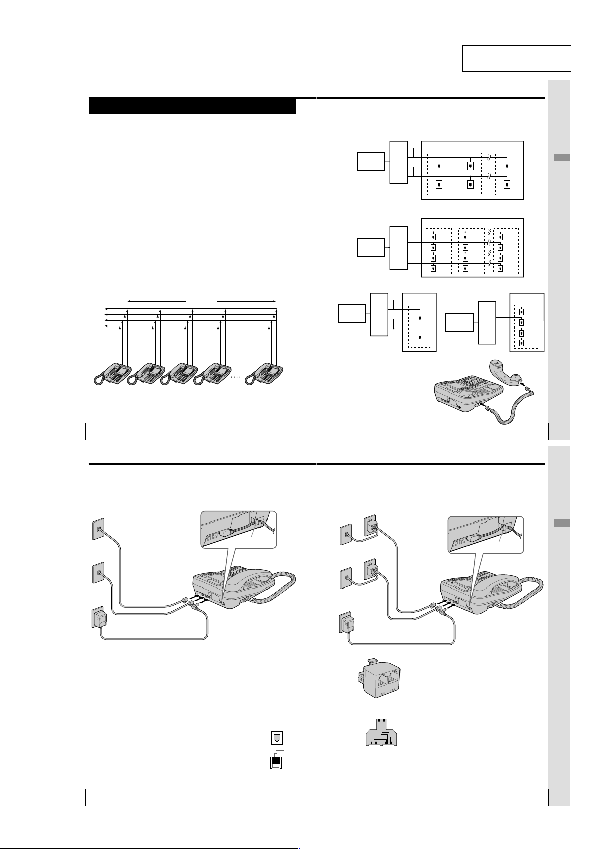
You can connect a maximum of 16 phones (IT-M704 or IT-M804) to use
your phone as an intercom phone, in addition to using as the 4-line
telephone.
To use the intercom features, you must connect all phones
(IT-M704 or IT-M804) to the LINE 1 jack correctly.
If you set the dialing mode and date and time on this phone after
connecting other phones, these settings will be set automatically to
every phone.
If you want to hang the phone on the wall, mount the phone first (see
page 44).
L1
L2
L3
L4
300 feet
SECTION 1
GENERAL
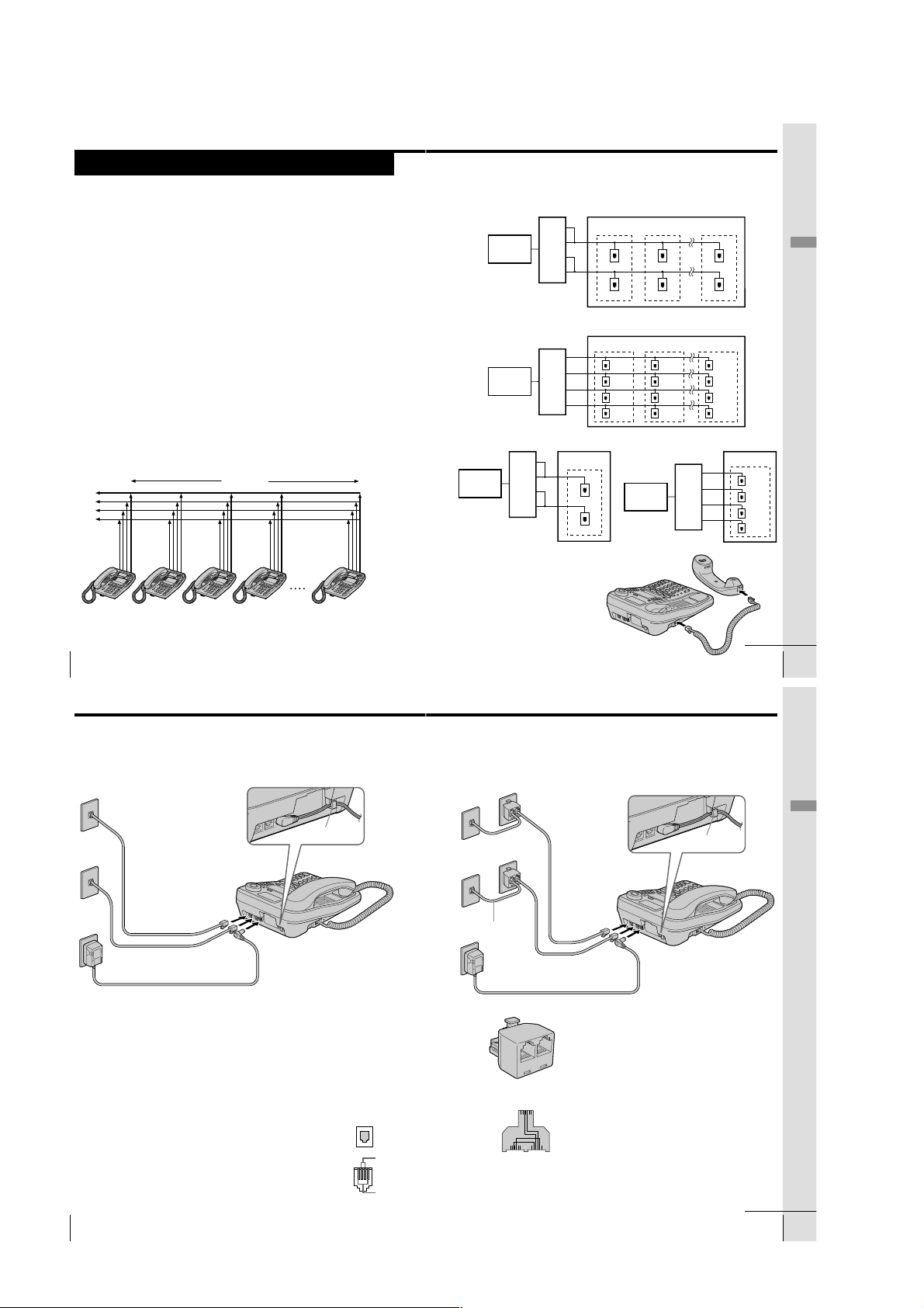
The connection method differs according to the conditions of indoor wiring.
[Wiring 1]
Conduct connections follow the procedure in “To connect the phone to two outlets having two
lines” on page 10.
[Wiring 2]
Conduct connections follow the procedure in “To connect the phone to four separate outlets” on
page 11.
[Wiring 3, 4]
When there is only one outlet for one telephone, wiring work is necessary.
Telephone
Office
Telephone
Office
Telephone
Office
Line1
Line2
Line3
Line4
Line1
Line2
Line3
Line4
Line1
Line2
Line3
Line4
This section is extracted
from instruction manual.
To a telephone To a telephone To a telephone
Line1
Line2
Line3
Line4
Line1, 2
Line3, 4
To a telephone
Telephone
Office
Line1
Line2
Line3
Line4
Line1, 2
Line3, 4
To a telephone
To a telephone
Line1, 2
Line3, 4
Line1
Line2
Line3
Line4
Getting Started
Line1, 2
Line3, 4
To a telephone
Line1
Line2
Line3
Line4
To a telephone
Line1
Line2
Line3
Line4
TEL-1 TEL-2 TEL-3 TEL-4 TEL-16
Note
If the each line is not connected correctly, you cannot use the functions of this
phone.
US
Getting Started
8
Step 2: Setting up the phone (continued)
To connect the phone to two outlets having two lines
To the telephone outlets
Line 1, 2
Line 3, 4
To an AC outlet
Tips
• If your telephone outlet is not modular, contact your telephone service
• L1 is the first phone line connected to center pair of wires. L2 is the second
US
Getting Started
10
1
Telephone line
cords (supplied)
2
AC power adaptor
(supplied AC-T71)
company for assistance.
phone line connected to outer pair of wires.
To “LINE 1/
LINE 1+2”
To “LINE 3/
LINE 3+4”
1
Connect the telephone line cords to the “LINE
1/LINE 1+2” and “LINE 3/LINE 3+4” jacks
and to the telephone outlets.
2
Connect the AC power adaptor to the DC IN
12V jack and to an AC outlet.
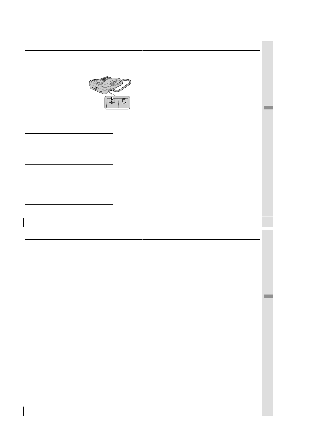
To DC IN 12V
Hook the cord.
Modular
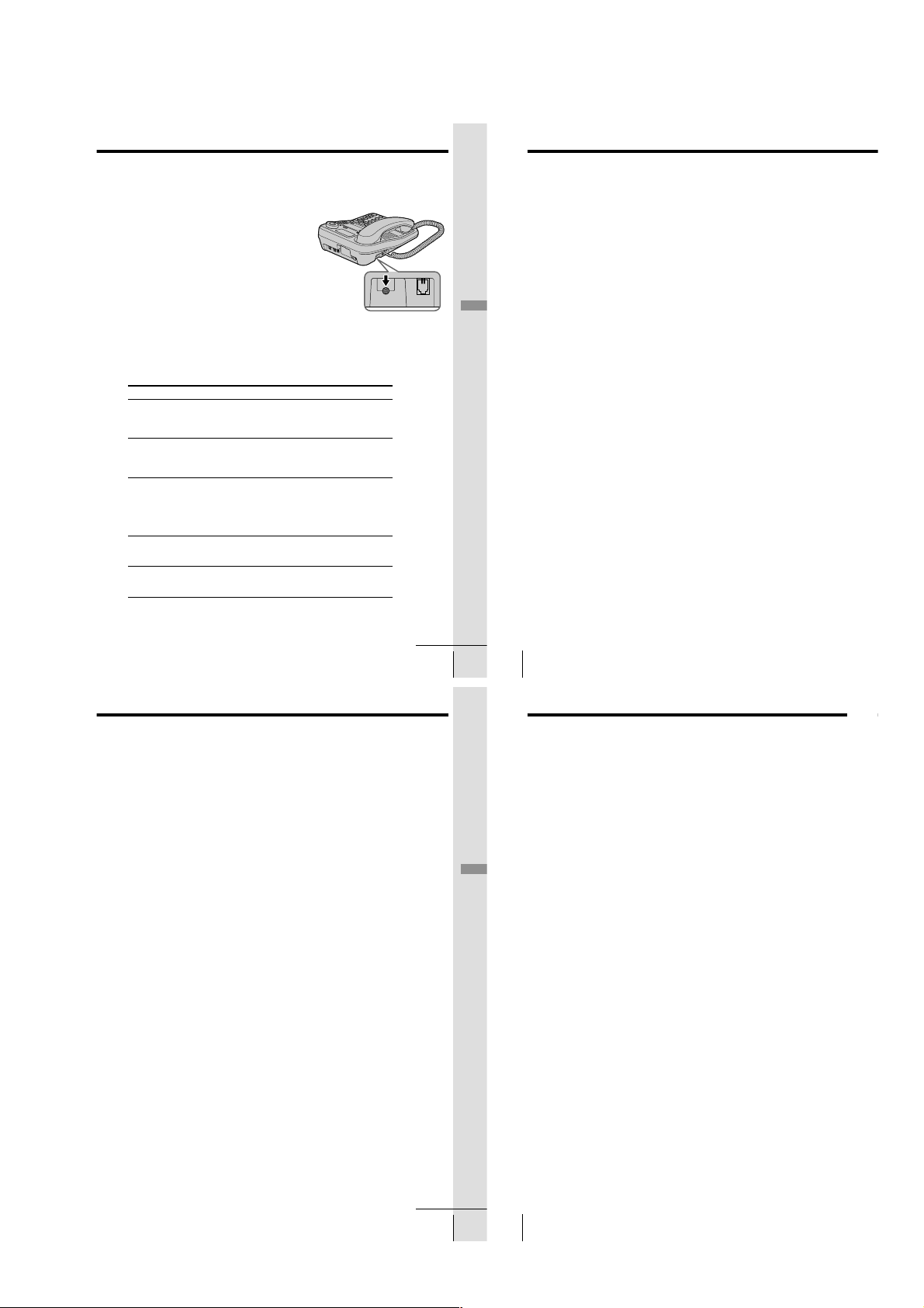
To connect the handset
Connect one end of the handset cord to
the handset and the other end to the
HANDSET jack on the phone.
To HANDSET jack
continued
Getting Started
US
9
To connect the phone to four separate outlets
If you have single line outlet, you need two Two-Line adaptors (not
supplied) to connect the phone to the four separate outlets.
To the telephone outlets
1
Two-Line adaptors
(not supplied)
Line 1
Line 2
2, 3
Telephone line
Line 3
Line 4
Telephone line
cord (not supplied)
4
AC power adaptor
(supplied AC-T71)
To an AC outlet
Two-Line adaptor
L1
L2
Two-Line adaptor
interconnection
Note
The Duplex Jack adaptor cannot be used as the adaptor, which is used in step1.
cords (supplied)
To “LINE 1/
LINE 1+2”
To “LINE 3/
LINE 3+4”
To DC IN 12V
1
Connect the Two-Line adaptors to
the line 1 and line 3 outlets.
2
Connect the telephone line cords to
the “LINE 1/LINE 1+2” and “LINE
3/LINE 3+4” jacks and to the TwoLine adaptors.
3
Connect the telephone line cords to
the Two-Line adaptors and to the
line 2 and line 4 outlets.
4
Connect the AC power adaptor to
the DC IN 12V jack and to an AC
outlet.
Hook the cord.
Getting Started
continued
Getting Started
US
11
– 3 –
Page 4
Step 2: Setting up the phone (continued)
LINE SELECTDATA
L2 L3 L4
DATA LINE SELECTDATA
L2 L3 L4
Step 2: Setting up the phone (continued)
Notes
• Conduct connections instructed on page 10 or 11 first, when
inserting battery for backup (not supplied) in case for a power
failure. If “POWER FAILURE” remains displayed when you
connect the AC power adaptor to an AC outlet for the first
time, remove the battery from the phone and unplug the AC
power adaptor, then plug it into an AC outlet.
• Use only the supplied AC-T71 AC power adaptor. Do not use
any other AC power adaptor.
• Connect the AC power adaptor to a continuous power
supply.
• Place the phone close to the AC outlet so that you can unplug
the AC power adaptor easily.
Tips
• Phones other than the IT-M704 and IT-M804 phones cannot be
connected to LINE 1 jack.
• Connection and utilization of Private Branch Exchange (PBX)
is not possible.
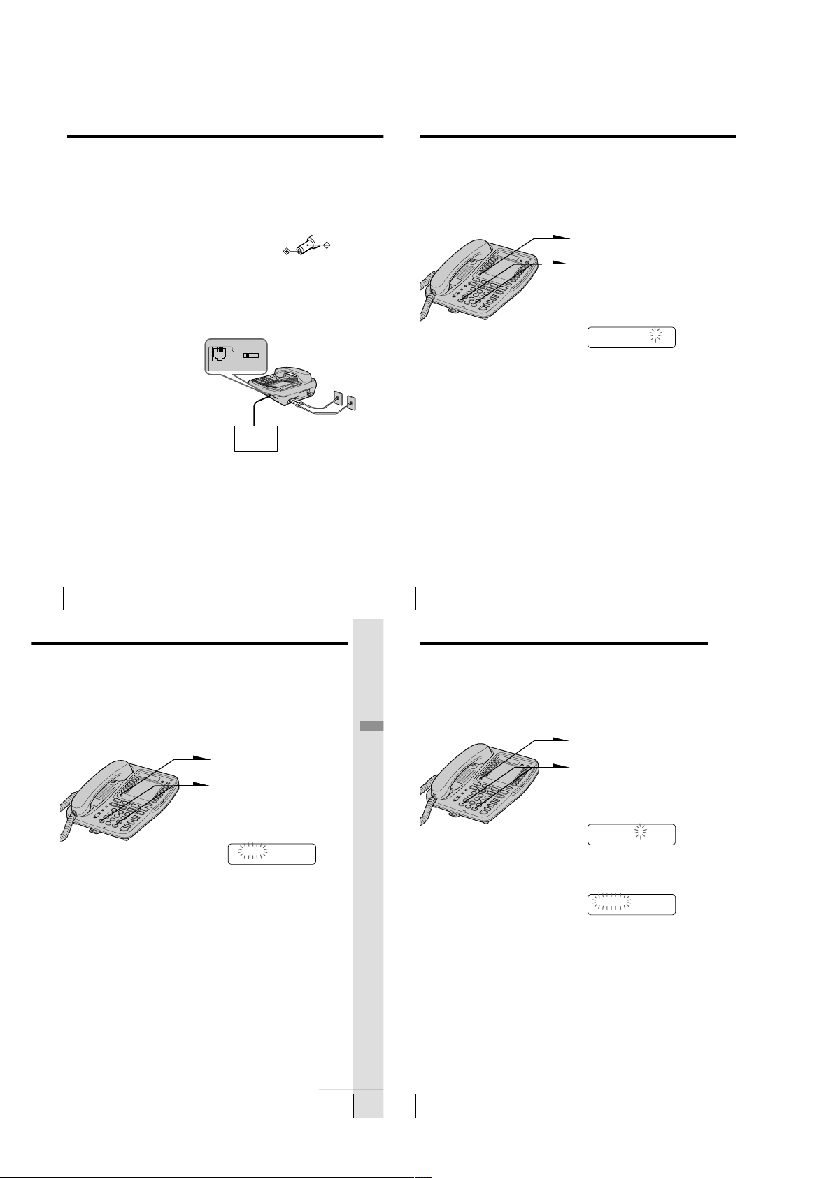
Connecting a computer or FAX
You can connect a computer or FAX, etc. to
the DATA jack.
For the line to be used for data
communication, select L2, L3 or L4 using
the DATA LINE SELECT switch.
Notes
•“LINE 2”, “LINE 3” or “LINE 4” is used for
receiving or sending computer or FAX data in
addition to making or receiving calls.
If a call comes in on the line selected with the
“call waiting” service while a computer or
FAX connected to the “DATA” jack is
receiving or sending data, that data may be
effected.
If you have data communication frequently,
we recommend that you and your callers use
the line selected for data communication only.
• Connection to ADSL devices is not possible.
• Noise may occasionally be heard on other
lines during data communication depending
on the condition of the indoor wiring.
To “DATA”
Computer
FAX
or
Polarity of the plug
To “LINE 1/LINE 1+2”
and “LINE 3/LINE 3+4”
Assigning station number
Ensure to connect all phones (IT-M704 or IT-M804) to LINE 1 jack
correctly, and then assign the station number to all phones. To confirm
the assigned station number is set correctly, make an intercom call one
another. See “Talking between the phones” on page 37.
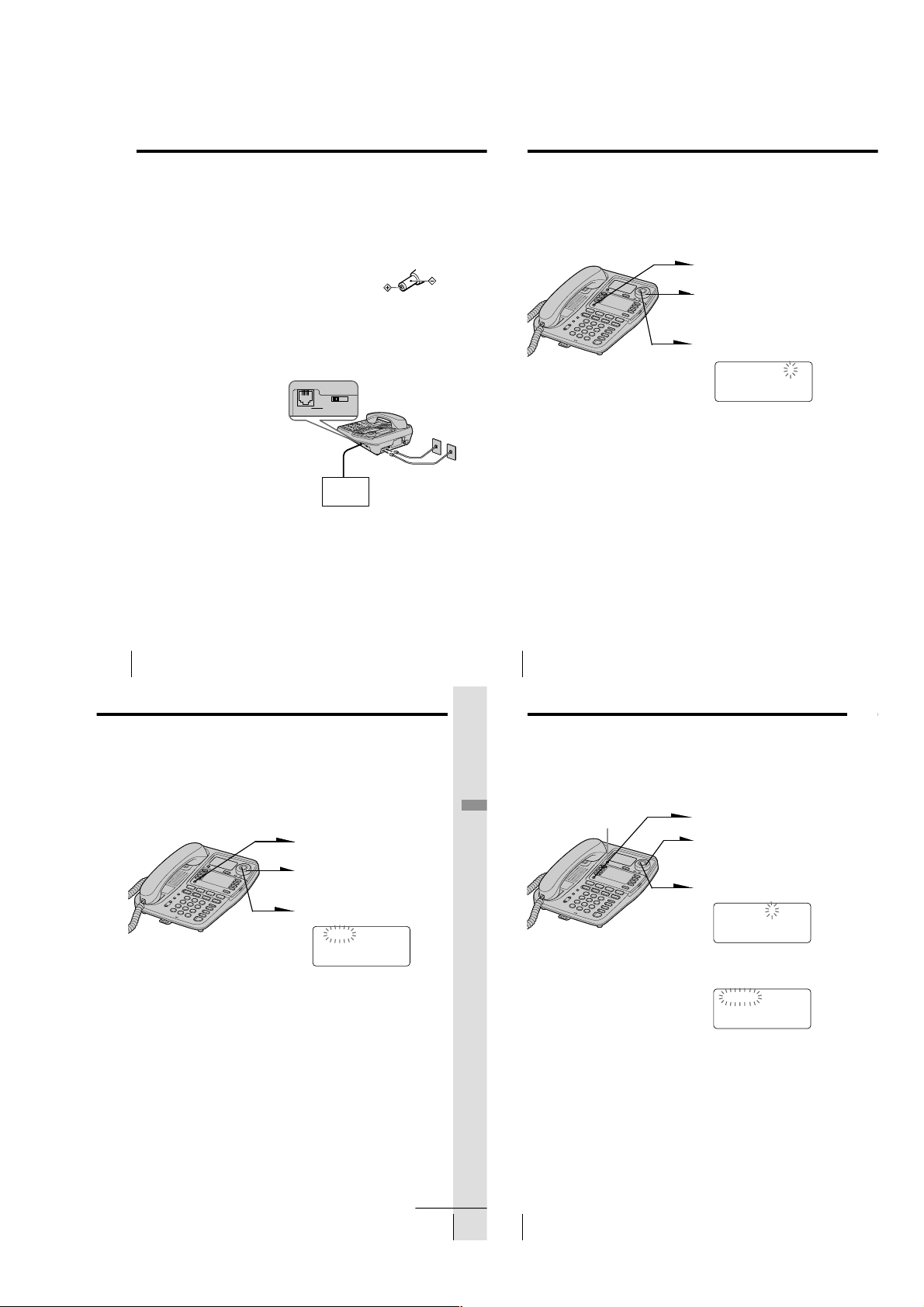
1
Press (PROGRAM).
2
Press b(*) or (#)B until
“STATION #” appears on the
display.
3
Press (PROGRAM).
STATION #=??
4
Enter the two digits station
number (01 to 16) by pressing
the dialing keys.
5
Press (PROGRAM).
You will hear a long
confirmation beep.
Note
If the number already used for other phone or a number except for 01 to 16 is
entered in step 4, “INVALID NUMBER” will be displayed. Enter the different
number.
US
Getting Started
12
Choose the dialing mode
For the telephone to work properly, select an appropriate dialing
mode (tone or pulse).
When other phones (IT-M704 or IT-M804) are connected to the LINE 1
jack, the same dialing mode is automatically set to all the phones. Be
sure to connect the phones beforehand, and set the dialing mode.
1
Press (PROGRAM).
2
Press b(*) or (#)B until
“DIAL MODE” appears on the
display.
3
Press (PROGRAM).
TONE PULSE
4
Press b(*) or (#)B to choose
the dialing mode (“TONE” or
“PULSE”), and then press
(PROGRAM).
You will hear a long
confirmation beep.
Notes
• Do not allow more than 20 seconds to elapse between each step of the
procedure.
• The dialing mode cannot be set for every line.
If you aren’t sure of your dialing system
Make a trial call with the dialing mode set to “TONE”.
If the call connects, leave the setting as is; otherwise, set to “PULSE”.
US
Getting Started
14
Step 2: Setting up the phone (continued)
Enabling/disabling the line
When you may not use all four lines, you need to disable the unused
line for the telephone to work properly.
This setting can be set up at each phone separately.
Getting Started
Note
You cannot disable the line 1.
(ERASE/CLEAR)
1
Press (PROGRAM).
2
Press b(*) or (#)B until
“DISABLE LINE” appears on
the display.
3
Press (PROGRAM).
LINE2
4
Press b(*) or (#)B to choose
the line you want to change, and
then press (PROGRAM).
ENABLE DISABLE
5
Press b(*) or (#)B to choose
“ENABLE” or “DISABLE”, and
then press (PROGRAM).
The line next to the selected line
will flash and you will hear a
long confirmation beep.
Repeat steps 4 and 5 for other
line setting, if necessary.
To end the setting, press
(ERASE/CLEAR).
continued
Getting Started
US
15
– 4 –
US
16
Getting Started
Page 5
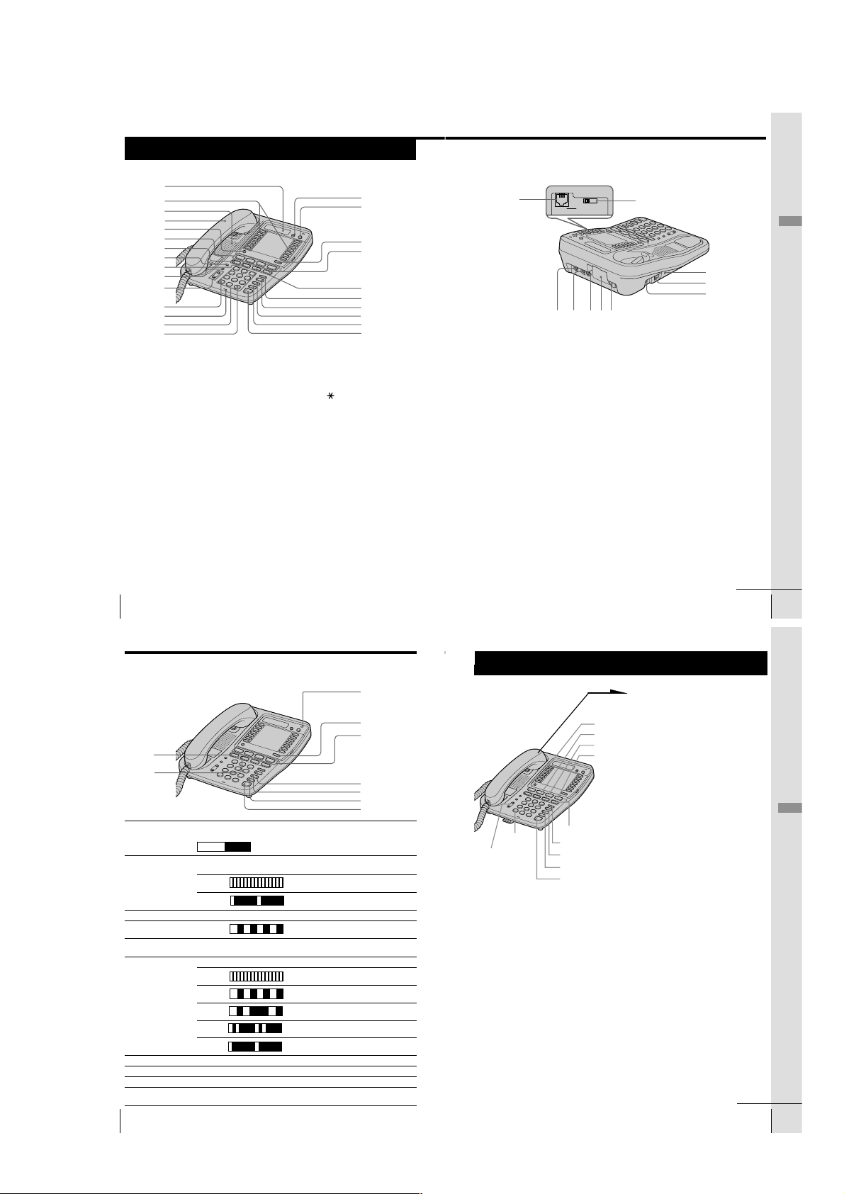
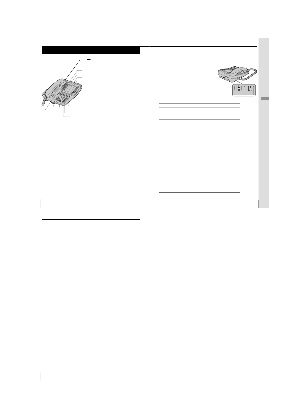
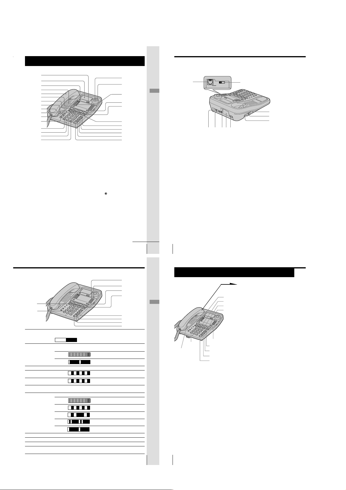
Identifying the parts
L2 L3 L4
Refer to the pages indicated in parentheses for details.
1
2
3
4
5
6
7
8
9
q;
qa
qs
qd
qf
qg
1 Display window
2 One-touch dial buttons (p. 31)
Used to store numbers on the onetouch dial.
3 Speaker
4 Handset (p. 9, 23, 28)
5 PROGRAM button
(p. 14, 31)
Used to access the menu.
6 LINE buttons (1, 2, 3, 4)
(p. 23, 28)
Lets you make or receive a call.
7 INTERCOM button (p. 37, 42)
Used to make an intercom call.
8 ALL PAGE button (p. 40)
Used to page all phones through
the speakerphone.
9 CONF (conference) button
(p. 34, 41)
Lets you talk with two parties at the
same time.
US
Getting Started
20
qh
qj
qk
ql
w;
wa
ws
wd
wf
wg
q; PAGE button (p. 39)
Used to page the other phone.
qa VOLUME +/- button (p. 24, 29)
qs TONE b button (p. 24)
Allows you to switch temporarily to
tone dialing.
qd MIC (microphone)
qf Dialing keys (p. 23)
qg # B button (p. 14)
qh ERASE/CLEAR button (p. 33, 36)
Used to erase a stored one-touch
dialing memory, end the operation
during the procedure.
qj FLASH button (p. 29)
Switches to a second call if you
have “call waiting” service, or lets
you make a new call.
qk LOWER button (p. 31)
Used to store numbers in the
second memory of a one-touch dial
button.
wh
wlwk
DATA LINE SELECTDATA
e;ea es
ql HOLD button (p. 24, 29)
Puts a call on hold.
w; TRANSFER button (p. 42)
Used to transfer a call.
wa REDIAL/PAUSE button (p. 26)
Redials the last number called,
inserts a pause in the dialing
sequence.
ws BUSY REDIAL button (p. 27)
Redials the last number called
automatically when the line is busy.
wd MUTING button (p. 24, 29)
Mutes your voice during a
conversation.
wf DO NOT DISTURB button
(p. 30)
Used to turn off the call ringing and
voice from the speaker.
wg SPEAKERPHONE (HEADSET)
button (p. 23, 24)
Used to make or receive a call
through the speakerphone or the
headset.
wj
ed
ef
eg
wh DATA jack (p. 12)
wj DATA LINE SELECT switch
(p. 12)
Used to select the line for data
communication.
wk LINE 1/LINE 1+2 jack (p. 10, 44)
wl LINE 3/LINE 3+4 jack (p. 10, 44)
e; DC IN 12V jack (p. 10)
ea Battery compartment (p. 45)
es Hook for AC power adaptor
cord (p. 10)
ed RESET button (p. 48)
ef HANDSET jack (p. 9)
eg I (HEADSET) jack (p. 24, 29)
continued
Getting Started
Getting Started
US
21
Identifying the parts (continued)
Lamp indications
eh
ej
Lamp/button Lighting pattern Status
eh INTERCOM Lights up Calling extension from your phone or
ej CONF Lights up This function is activated.
ek MESSAGES Flashes There are voice mail messages.
el LOWER Lights up Selecting the second memory of the
r; LINE 1 to 4 Lights up You are using this line.
ra BUSY REDIAL Lights up This function is activated.
rs MUTING Lights up This function is activated.
rd DO NOT DISTURB Lights up This function is activated.
rf SPEAKERPHONE Lights up Talking through the speakerphone or
(HEADSET) headset, paging or busy redialing.
US
Getting Started
22
Lights up OFF
Flashes Receiving an intercom call.
Flashes Other phone using extension.
Flashes Receiving a call.
Flashes Call being held on your phone line or
Flashes Call being held on other phone line.
Flashes Receiving a transferred call.
Flashes Line is used by other phone.
conversation available.
one-touch dial button.
transferred call being made.
Basics
Making calls
ek
el
r;
ra
rs
rd
rf
TONE b(*)
(VOLUME)
Note
If there is a line put on hold, you cannot make a call by just picking up the
handset and pressing (SPEAKERPHONE) in step 1. Press a line button that is not
used first, and then dial the phone number.
Tip
If you pick up the handset during speakerphone conversation, it will change to
handset conversation, and conversely when you press (SPEAKERPHONE)
during handset conversation, it becomes speakerphone conversation.
(HOLD)
(REDIAL/PAUSE)
(BUSY REDIAL)
(MUTING)
(SPEAKERPHONE)
(LINE 1)
(LINE 2)
(LINE 3)
(LINE 4)
1
Pick up the handset (or press
(SPEAKERPHONE)).
“=== TALK ===” appears on
the display, and then the
operation duration in hours,
minutes and seconds is
displayed.
The connected line button lights
up.
When you want to select the line
beforehand, press (LINE 1),
(LINE 2), (LINE 3) or (LINE 4).
The corresponding line button
lights up.
2
Dial the phone number.
The phone number dialed
appears on the display.
3
When you’re done talking,
replace the handset in the cradle
(or press (SPEAKERPHONE)).
The disconnected line button
goes off.
continued
Basics
Basics
US
23
– 5 –
Page 6
Making calls (continued)
HANDSET
Making calls when the headset is connected
When the TL-HD1 headset (not supplied) is connected to the I
(HEADSET) jack, you can talk through the headset.
1
Press (SPEAKERPHONE) (HEADSET).
The SPEAKERPHONE lamp lights up.
2
Dial the phone number.
3
When you’re done talking, press
(SPEAKERPHONE) (HEADSET).
The SPEAKERPHONE lamp goes off.
Notes
• If the headset is not connected, you will make a call through the
speakerphone in step 1.
• If there is a line put on hold, you cannot make a call by just pressing
(SPEAKERPHONE) (HEADSET) in step 1. Press a line button that is not used
first, and then dial the phone number.
Additional tasks
To Do this
Adjust the handset or During phone conversation, press (VOLUME)
headset volume (+) or (--). Each press of (VOLUME)(+) or (--)
Adjust the speaker volume During speakerphone conversation, press
Put a call on hold Press (HOLD). The line button on which a call is
Mute your voice Press (MUTING) to disable the microphone. The
Switch to tone dialing Press TONE b(*) after you’re connected.
temporarily The line will remain in tone dialing until
switches the handset or headset volume
between “HIGH”, “MID” (middle) and “LOW”.
(VOLUME)(+) or (--). Each press of
(VOLUME)(+) or (--) switches the speaker
volume by one of 16 levels.
put on hold will flash.
Press (LINE 1), (LINE 2), (LINE 3) or (LINE 4)
that is flashing to resume the conversation.
The corresponding line button can be pressed
on every phone.
MUTING lamp lights up. Press (MUTING) again
to cancel.
disconnected.
Notes
• When another extension connected to line is in use, the line button flashes .
• When another call comes in on the other line, the corresponding line button
flashes and two beeps are heard from the speaker, but the phone won’t ring.
(see page 30).
• If a call is put on hold for more than about three minutes, you will hear an
alarm.
Tips
• You can switch to speakerphone during conversation by pressing
(SPEAKERPHONE). Then you can replace the handset in the cradle.
To switch back to the handset, pick up the handset again.
• When you pick up the handset or press (SPEAKERPHONE), the vacant line is
automatically connected from line 1 to line 4. When neither line is in use, line
I
1 is connected.
To obtain the best speakerphone performance
• You may not be able to hear the other party’s voice in a noisy place.
Therefore, use the speakerphone in a quiet room.
• Do not bring your hand or other objects too close to the microphone
or you will hear a shrill noise (“feedback”).
• When the speaker volume is loud, or the telephone has been placed
close to a wall, you may find that the volume drops suddenly. This is
due to a circuit in the telephone designed to protect against
feedback. In such cases, lower the speaker volume slightly.
Basics
US
Basics
24
Making calls (continued)
Redialing
1
Pick up the handset (or press (SPEAKERPHONE)).
“=== TALK ===” appears on the display.
Press (LINE 1), (LINE 2), (LINE 3) or (LINE 4) to select the
line, if necessary.
The corresponding line button lights up.
2
Press (REDIAL/PAUSE) to redial the last number dialed.
The last number dialed appears on the display and is
automatically redialed.
Notes
• The last number dialed cannot be stored separately for each line. It is the very
last one you have dialed using any line.
• If the last number dialed exceeds 32 digits or if it is erased, the number
cannot be redialed.
Tip
When the redialed number exceeds 16 digits, the first 16 digits are displayed,
and then the remaining digits are displayed one by one while the displayed
numbers move from right to left across the display.
To check the last phone number dialed
When not making a call, press (REDIAL/PAUSE).
The number appears on the display for 20 seconds.
To dial the number, pick up the handset (or press (SPEAKERPHONE))
while the number is displayed.
Note
“NO DATA” will appear on the display if the last dialed number exceeds 32
digits or if it is erased.
To erase the last phone number dialed
While the phone is not in use, press (REDIAL/PAUSE) twice within 20
seconds.
The number will be erased from the memory.
Busy redialing
If the other line you called is busy, the phone will automatically redial
the last number dialed up to 10 times every 30 seconds until the call is
connected.
When not making a call, press (BUSY REDIAL).
The BUSY REDIAL lamp, MUTING lamp, SPEAKERPHONE lamp
and selected line button light up and the last number dialed appears
on the display.
Notes
• Busy redialing is canceled when you press (BUSY REDIAL), or receive or
make a call during busy redialing.
• If the last number dialed exceeds 32 digits or if it is erased, the number
cannot be redialed.
Making another call while talking
Example: Making a call on line 2 while talking on line 1
1
Press (HOLD) while talking.
The line 1 is put on hold and the LINE 1 button flashes
slowly.
2
Press (LINE 2).
3
Dial a phone number for the second party.
Now you can talk to the second party on line 2.
To disconnect line 2, press (LINE 1).
Notes
• If you do not press (HOLD) in step 1, line 1 will be disconnected.
• If a call is put on hold for more than about three minutes, you will hear an
alarm.
To talk with two parties at the same time using two lines, see “Having
a three-way conference call” on page 34.
continued
Basics
US
25
Basics
26
US
Basics
Basics
US
27
– 6 –
Page 7
Receiving calls
HANDSET
1
When you hear the phone ring;
• Pick up the handset from the
(LINE 1)
(PROGRAM)
(VOLUME)
b(*)
(#)B
(LINE 2)
(LINE 3)
(LINE 4)
(FLASH)
(HOLD)
(MUTING)
(DO NOT DISTURB)
(SPEAKERPHONE)
When calls come in on two or more lines at the same time
Press (LINE 1), (LINE 2), (LINE 3) or (LINE 4) whichever button
is flashing.
To put a call on hold or disconnect the line, see “Receiving a
call while talking” on page 30.
US
Basics
28
phone (or press
(SPEAKERPHONE)).
• Press (LINE 1), (LINE 2),
(LINE 3) or (LINE 4)
whichever button is flashing.
The SPEAKERPHONE lamp
lights up and you can talk
through the speakerphone. To
talk through the handset, pick
up it from the cradle.
The connected line button lights
up.
“=== TALK ===” appears on
the display and the display also
shows the operation duration in
hours, minutes and seconds.
2
When you’re done talking,
replace the handset in the cradle
(or press (SPEAKERPHONE)).
The disconnected line button
goes off.
Receiving calls when the headset is connected
When the TL-HD1 headset (not supplied) is connected to the I
(HEADSET) jack, you can talk through the headset.
1
When you hear the phone ring, press
(SPEAKERPHONE) (HEADSET).
or
The SPEAKERPHONE lamp lights up.
2
When you’re done talking, press
(SPEAKERPHONE) (HEADSET).
The SPEAKERPHONE lamp goes off.
Note
If the headset is not connected, you will receive a call
through the speakerphone in step 1.
Additional tasks
To Do this
Adjust the handset or During phone conversation, press (VOLUME)
headset volume (+) or (--). Each press of (VOLUME)(+) or (--)
Adjust the speaker volume During speakerphone conversation, press
Put a call on hold Press (HOLD). The line button on which a call is
Adjust the ringer volume Press (PROGRAM). Press b(*) or (#)B up
Mute your voice Press (MUTING) to disable the microphone. The
Switch to another call on Press (FLASH).
(“call waiting” service*) Press (FLASH) again to return to the first caller.
* You need to subscribe to the service from your telephone company.
switches the handset or headset volume
between “HIGH”, “MID” (middle) and “LOW”.
(VOLUME)(+) or (--). Each press of
(VOLUME)(+) or (--) switches the speaker
volume by one of 16 levels.
put on hold will flash.
Press (LINE 1), (LINE 2), (LINE 3) or (LINE 4)
that is flashing to resume the conversation.
The corresponding line button can be pressed
on every phone.
until “RING VOLUME” appears on the
display, and then press (PROGRAM). Press
b(*) or (#)B to choose “HIGH”, “MID”
(middle), “LOW” or “OFF”, and then press
(PROGRAM). You will hear (monitor) the phone
ring with the adjusted level. While the phone is
ringing, you can adjust the ringer volume by
pressing (VOLUME)(+) or (--), however, the
ringer volume cannot be set to “OFF”.
MUTING lamp lights up. Press (MUTING) again
to cancel.
I
Basics
continuedcontinued
Basics
US
29
Receiving calls (continued)
Notes
• When another phone connected to line is in use, the line button flashes
slowly.
• If a call is put on hold for more than about three minutes, you will hear an
alarm.
Using Do Not Disturb
You can turn off the outside call and intercom call ringing of all the
lines and voice from the speaker during a Page and an All Page using
this function. However, when a call comes in, “** RINGING **” will
be displayed even if this function is activated.
Making calls is available even if this function is activated.
While the phone is not in use or the phone is ringing, you can press
(DO NOT DISTURB).
The DO NOT DISTURB lamp lights up.
To cancel this function, press (DO NOT DISTURB) again.
Note
An outside call cannot be transferred to the phone with the “DO NOT
DISTURB” function activated.
Receiving a call while talking
If another call comes in while talking on the other line, the
corresponding line button will flash and two beeps will be heard from
the speaker.
Example: Receiving a call on line 2 while talking on line 1
1
Press (HOLD).
Line 1 is put on hold and the LINE 1 button flashes slowly.
2
Press (LINE 2).
Now you can talk to the other caller on line 2.
To disconnect line 2, press (LINE 1).
Note
If you do not press (HOLD) in step 1, line 1 will be disconnected.
To talk with two parties at the same time using both line 1 and line 2,
see “Having a three-way conference call” on page 34.
US
Basics
30
– 7 –
Page 8
1-2. IT-M804 MODEL
Step 2
Setting up the phone
Do the following steps:
• Connect the phone
• Assigning station number
• Choose the dialing mode
• Enabling/disabling the line
Note on installation
Install the unit:
• on a level surface
• away from heat sources, such as radiators, airducts, and sunlight
• away from excessive moisture, extremely low temperatures, dust, mechanical
vibration, or shock
Connect the phone
You can connect a maximum of 16 phones (IT-M804 or IT-M704) to use
your phone as an intercom phone, in addition to using as the 4-line
telephone.
To use the intercom features, you must connect all phones
(IT-M804 or IT-M704) to the LINE 1 jack correctly.
If you set the dialing mode, area codes and date and time on this
phone after connecting other phones, these settings will be set
automatically to every phone. Moreover, the Caller ID data can be
viewed on every connected phone.
If you want to hang the phone on the wall, mount the phone first (see
page 70).
L1
L2
L3
L4
300 feet
The connection method differs according to the conditions of indoor wiring.
[Wiring 1]
Conduct connections follow the procedure in “To connect the phone to two outlets having two
lines” on page 12.
Line1
Office
Office
Line2
Line3
Line4
Line1
Line2
Line3
Line4
Line1
Line2
Line3
Line4
Telephone
[Wiring 2]
Conduct connections follow the procedure in “To connect the phone to four separate outlets” on
page 13.
Telephone
[Wiring 3, 4]
When there is only one outlet for one telephone, wiring work is necessary.
Telephone
Office
To a telephone To a telephone To a telephone
Line1
Line2
Line3
Line4
Line1, 2
Line3, 4
To a telephone
Telephone
Office
Line1
Line2
Line3
Line4
Line1, 2
Line3, 4
To a telephone
To a telephone
Line1, 2
Line3, 4
Line1
Line2
Line3
Line4
Line1, 2
Line3, 4
To a telephone
Line1
Line2
Line3
Line4
To a telephone
Line1
Line2
Line3
Line4
Getting Started
TEL-1 TEL-2 TEL-3 TEL-4 TEL-16
Note
If the each line is not connected correctly, you cannot use the functions of this
phone.
US
Getting Started
10
Step 2: Setting up the phone (continued)
To connect the phone to two outlets having two lines
To the telephone outlets
Line 1, 2
Line 3, 4
To an AC outlet
Tips
• If your telephone outlet is not modular, contact your telephone service
• L1 is the first phone line connected to center pair of wires. L2 is the second
US
Getting Started
12
1
Telephone line
cords (supplied)
2
AC power adaptor
(supplied AC-T71)
company for assistance.
phone line connected to outer pair of wires.
To “LINE 1/
LINE 1+2”
To “LINE 3/
LINE 3+4”
1
Connect the telephone line cords to the “LINE
1/LINE 1+2” and “LINE 3/LINE 3+4” jacks
and to the telephone outlets.
2
Connect the AC power adaptor to the DC IN
12V jack and to an AC outlet.
To DC IN 12V
Hook the cord.
Modular
To connect the handset
Connect one end of the handset cord to
the handset and the other end to the
HANDSET jack on the phone.
To HANDSET jack
continued
Getting Started
US
11
To connect the phone to four separate outlets
If you have single line outlet, you need two Two-Line adaptors (not
supplied) to connect the phone to the four separate outlets.
To the telephone outlets
1
Two-Line adaptors
(not supplied)
Line 1
Line 2
2, 3
Telephone line
LINE 2 PHONE
LINE 1
cords (supplied)
To “LINE 1/
LINE 1+2”
To “LINE 3/
LINE 3+4”
To DC IN 12V
1
Connect the Two-Line adaptors to
the line 1 and line 3 outlets.
2
Connect the telephone line cords to
the “LINE 1/LINE 1+2” and “LINE
3/LINE 3+4” jacks and to the TwoLine adaptors.
3
Connect the telephone line cords to
the Two-Line adaptors and to the
line 2 and line 4 outlets.
4
Connect the AC power adaptor to
the DC IN 12V jack and to an AC
outlet.
Line 3
Line 4
Telephone line
cord (not supplied)
4
AC power adaptor
(supplied AC-T71)
To an AC outlet
Two-Line adaptor
L1
L2
Note
The Duplex Jack adaptor cannot be used as the adaptor, which is used in step1.
LINE 2 PHONE
Two-Line adaptor
interconnection
Hook the cord.
Getting Started
continued
Getting Started
US
13
– 8 –
Page 9
DATA LINE SELECTDATA
L2 L3 L4
Step 2: Setting up the phone (continued)
Step 2: Setting up the phone (continued)
Notes
• Conduct connections instructed on page 12 or 13 first, when
inserting battery for backup (not supplied) in case for a power
failure. If “POWER FAILURE” appears on the display instead
of “NO AREA CODE” when you connect the AC power
adaptor to an AC outlet for the first time, remove the battery
from the phone and unplug the AC power adaptor, then plug
it into an AC outlet.
• Use only the supplied AC-T71 AC power adaptor. Do not use
any other AC power adaptor.
• Connect the AC power adaptor to a continuous power
supply.
• Place the phone close to the AC outlet so that you can unplug
the AC power adaptor easily.
Tips
• Phones other than the IT-M804 and IT-M704 phones cannot be
connected to LINE 1 jack.
• Connection and utilization of Private Branch Exchange (PBX)
is not possible.
Connecting a computer or FAX
You can connect a computer or FAX, etc. to
the DATA jack.
For the line to be used for data
communication, select L2, L3 or L4 using
the DATA LINE SELECT switch.
Notes
•“LINE 2”, “LINE 3” or “LINE 4” is used for
receiving or sending computer or FAX data in
addition to making or receiving calls.
If a call comes in on the line selected with the
“call waiting” service while a computer or
FAX connected to the DATA jack is receiving
or sending data, that data may be effected.
If you have data communication frequently,
we recommend that you and your callers use
the line selected for data communication only.
• Connection to ADSL devices is not possible.
• Noise may occasionally be heard on other
lines during data communication depending
on the condition of the indoor wiring.
To “DATA”
Computer
FAX
or
Polarity of the plug
To “LINE 1/LINE 1+2”
and “LINE 3/LINE 3+4”
Assigning station number
Ensure to connect all phones (IT-M804 or IT-M704) to LINE 1 jack
correctly, and then assign the station number to all phones. To confirm
the assigned station number is set correctly, make an intercom call one
another. See “Talking between the phones” on page 63.
1
Press (PROGRAM).
2
Turn Jog Dial up until
“STATION #” appears on the
display.
3
Press Jog Button.
STATION #=??
4
Enter the two digits station
number (01 to 16) by pressing
the dialing keys.
5
Press Jog Button.
You will hear a long
confirmation beep.
Note
If the number already used for other phone or a number except for 01 to 16 is
entered in step 4, “INVALID NUMBER” will be displayed. Enter the different
number.
Tip
You can press (PROGRAM) instead of Jog Button in the procedure above.
US
Getting Started
14
Choose the dialing mode
For the telephone to work properly, select an appropriate dialing
mode (tone or pulse).
When other phones (IT-M804 or IT-M704) are connected to the LINE 1
jack, the same dialing mode is automatically set to all the phones. Be
sure to connect the phones beforehand, and set the dialing mode.
1
Press (PROGRAM).
2
Turn Jog Dial up until “DIAL
MODE” appears on the display.
3
Press Jog Button.
TONE PULSE
4
Turn Jog Dial to choose the
dialing mode (“TONE” or
“PULSE”), and then press Jog
Button.
You will hear a long
confirmation beep.
Notes
• Do not allow more than 20 seconds to elapse between each step of the
procedure.
• The dialing mode cannot be set for every line.
Tip
You can press (PROGRAM) instead of Jog Button in the procedure above.
If you aren’t sure of your dialing system
Make a trial call with the dialing mode set to “TONE”.
If the call connects, leave the setting as is; otherwise, set to “PULSE”.
continued
Getting Started
US
Getting Started
16
Step 2: Setting up the phone (continued)
Enabling/disabling the line
When you may not use all four lines, you need to disable the unused
line for the telephone to work properly.
This setting can be set up at each phone separately.
Getting Started
Note
You cannot disable the line 1.
Tip
US
17
You can press (PROGRAM) instead of Jog Button in the procedure above.
US
Getting Started
18
(ERASE/CLEAR)
1
Press (PROGRAM).
2
Turn Jog Dial up until
“DISABLE LINE” appears on
the display.
3
Press Jog Button.
LINE2
4
Turn Jog Dial to choose the line
you want to change, and then
press Jog Button.
ENABLE DISABLE
5
Turn Jog Dial to choose
“ENABLE” or “DISABLE”, and
then press Jog Button.
You will hear a long
confirmation beep and the line
next to the selected line will
flash on the display .
Repeat steps 4 and 5 for other
line setting, if necessary.
To end the setting, press
(ERASE/CLEAR).
– 9 –
Page 10
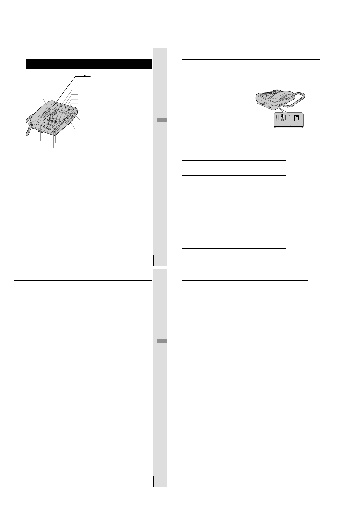
Identifying the parts
L2 L3 L4
Refer to the pages indicated in parentheses for details.
1
2
3
4
5
6
7
8
9
0
qa
qs
qd
qf
qg
qh
1 CALL WAITING/FLASH button
(p. 34, 60)
Switches to a second call if you
have “call waiting” service, or lets
you make a new call.
2 Display window (p. 37, 51)
3 ERASE/CLEAR button
(p. 40, 44, 53, 61)
Used to erase a stored one-touch
dialing and Phone Directory
memory or Caller ID data, end the
operation during the procedure.
4 Speaker
5 Handset (p. 11, 28, 33)
6 PROGRAM button
(p. 16, 37, 52)
Used to access the menu.
7 LINE buttons (1, 2, 3, 4)
(p. 28, 33)
Lets you make or receive a call.
8 INTERCOM button (p. 63, 67)
Used to make an intercom call.
9 ALL PAGE button (p. 66)
Used to page all phones through
the speakerphone.
0 CONF (conference) button
(p. 48, 67)
Lets you talk with two parties at the
same time.
qa PAGE button (p. 65)
Used to page the other phone.
qs VOLUME +/- button (p. 29, 34)
qd TONE button (p. 29)
Allows you to switch temporarily to
tone dialing.
qf MIC (microphone)
qg Dialing keys (p. 28)
qh # button (p. 58)
Used to change the number of
digits of the phone number in the
Caller ID list.
qj Jog Button (p. 16)
qk Jog dial (p. 16, 51)
qj
qk
ql
w;
wa
ws
wd
wf
wg
wh
wj
Getting Started
continued
Identifying the parts (continued)
Getting Started
ql One-touch dial buttons
w; LOWER button (p. 37)
wa HOLD button (p. 29, 34)
ws TRANSFER button (p. 68)
wd REDIAL/PAUSE button (p. 31)
wf BUSY REDIAL button (p. 32)
wg MUTING button (p. 29, 34)
US
US
Getting Started
26
25
wk
eae;
DATA LINE SELECTDATA
esed ef
(p. 37, 56)
Used to store numbers on the onetouch dial.
Used to store numbers in the
second memory of a one-touch dial
button.
Puts a call on hold.
Used to transfer a call.
Redials the last number called,
inserts a pause in the dialing
sequence.
Redials the last number called
automatically when the line is busy.
Mutes your voice during a
conversation.
wl
eg
eh
ej
wh
DO NOT DISTURB button
Used to turn off the call ringing and
voice from the speaker.
wj SPEAKERPHONE (HEADSET)
button (p. 28, 29)
Used to make or receive a call
through the speakerphone or the
headset.
(p. 35)
wk DATA jack (p. 14)
wl
DATA LINE SELECT switch
Used to select the line for data
communication.
(p. 14)
e; LINE 1/LINE 1+2 jack (p. 12, 70)
ea LINE 3/LINE 3+4 jack (p. 12, 70)
es DC IN 12V jack (p. 12)
ed Battery compartment (p. 71)
ef Hook for AC power adaptor
cord (p. 12)
eg RESET button (p. 74)
eh HANDSET jack (p. 11)
ej I (HEADSET) jack (p. 29, 34)
Lamp indications
ek
el
Lamp/button Lighting pattern Status
ek INTERCOM Lights up Calling extension from your phone or
el CONF Lights up This function is activated.
r; NEW CALL Flashes There is new data in the Caller ID list.
ra MESSAGES Flashes There are voice mail messages.
rs LOWER Lights up Selecting the second memory of the
rd LINE 1 to 4 Lights up You are using this line.
rf BUSY REDIAL Lights up This function is activated.
rg MUTING Lights up This function is activated.
rh DO NOT DISTURB Lights up This function is activated.
rj SPEAKERPHONE Lights up Talking through the speakerphone or
(HEADSET) headset, paging or busy redialing.
Lights up OFF
Flashes Receiving an intercom call.
Flashes Other phone using extension.
Flashes Receiving a call.
Flashes Call being held on your phone line or
Flashes Call being held on other phone line.
Flashes Receiving a transferred call.
Flashes Line is used by other phone.
conversation available.
one-touch dial button.
transferred call being made.
r;
ra
rs
rd
rf
rg
rh
rj
Getting Started
Basics
Getting Started
(VOLUME)
Note
If there is a line put on hold, you cannot make a call by just picking up the
handset and pressing (SPEAKERPHONE) in step 1. Press a line button that is not
used first, and then dial the phone number.
Tip
If you pick up the handset during speakerphone conversation, it will change to
handset conversation, and conversely when you press (SPEAKERPHONE)
during handset conversation, it becomes speakerphone conversation.
US
US
Basics
28
27
Making calls
TONE (*)
(HOLD)
(REDIAL/PAUSE)
(BUSY REDIAL)
(MUTING)
(SPEAKERPHONE)
(LINE 1)
(LINE 2)
(LINE 3)
(LINE 4)
1
Pick up the handset (or press
(SPEAKERPHONE)).
“=== TALK ===” appears on
the display, and then the
operation duration in hours,
minutes and seconds is
displayed.
The connected line button lights
up.
When you want to select the line
beforehand, press (LINE 1),
(LINE 2), (LINE 3) or (LINE 4).
The corresponding line button
lights up.
2
Dial the phone number.
The phone number dialed
appears on the display.
3
When you’re done talking,
replace the handset in the cradle
(or press (SPEAKERPHONE)).
The disconnected line button
goes off.
– 10 –
Page 11
Making calls when the headset is connected
I
HANDSET
When the TL-HD1 headset (not supplied) is connected to the I
(HEADSET) jack, you can talk through the headset.
1
Press (SPEAKERPHONE) (HEADSET).
The SPEAKERPHONE lamp lights up.
2
Dial the phone number.
3
When you’re done talking, press
(SPEAKERPHONE) (HEADSET).
The SPEAKERPHONE lamp goes off.
Notes
• If the headset is not connected, you will make a call through the
speakerphone in step 1.
• If there is a line put on hold, you cannot make a call by just pressing
(SPEAKERPHONE) (HEADSET) in step 1. Press a line button that is not used
first, and then dial the phone number.
Additional tasks
To Do this
Adjust the handset or During phone conversation, press (VOLUME)
headset volume (+) or (--). Each press of (VOLUME)(+) or (--)
Adjust the speaker volume During speakerphone conversation, press
Put a call on hold Press (HOLD). The line button on which a call is
Mute your voice Press (MUTING) to disable the microphone. The
Switch to tone dialing Press TONE (*) after you’re connected.
temporarily The line will remain in tone dialing until
switches the handset or headset volume
between “HIGH”, “MID” (middle) and “LOW”.
(VOLUME)(+) or (--). Each press of
(VOLUME)(+) or (--) switches the speaker
volume by one of 16 levels.
put on hold will flash.
Press (LINE 1), (LINE 2), (LINE 3) or (LINE 4)
that is flashing to resume the conversation.
The corresponding line button can be pressed
on every phone.
MUTING lamp lights up. Press (MUTING) again
to cancel.
disconnected.
Basics
Making calls (continued)
Notes
• When another extension connected to line is in use, the line button flashes.
• When another call comes in on the other line, the corresponding line button
flashes and two beeps are heard from the speaker, but the phone won’t ring.
(see page 36).
• If a call is put on hold for more than about three minutes, you will hear an
alarm.
Tips
• You can switch to speakerphone during conversation by pressing
(SPEAKERPHONE). Then you can replace the handset in the cradle.
To switch back to the handset, pick up the handset again.
• When you pick up the handset or press (SPEAKERPHONE), the vacant line is
automatically connected from line 1 to line 4. When neither line is in use, line
1 is connected.
To obtain the best speakerphone performance
• You may not be able to hear the other party’s voice in a noisy place.
Therefore, use the speakerphone in a quiet room.
• Do not bring your hand or other objects too close to the microphone
or you will hear a shrill noise (“feedback”).
• When the speaker volume is loud, or the telephone has been placed
close to a wall, you may find that the volume drops suddenly. This is
due to a circuit in the telephone designed to protect against
feedback. In such cases, lower the speaker volume slightly.
Redialing
1
Pick up the handset (or press (SPEAKERPHONE)).
“=== TALK ===” appears on the display.
Press (LINE 1), (LINE 2), (LINE 3) or (LINE 4) to select the
line, if necessary.
The corresponding line button lights up.
2
Press (REDIAL/PAUSE) to redial the last number dialed.
The last number dialed appears on the display and is
automatically redialed.
Notes
• The last number dialed cannot be stored separately for each line. It is the very
last one you have dialed using any line.
• If the last number dialed exceeds 32 digits or if it is erased, the number
cannot be redialed.
Tip
When the redialed number exceeds 16 digits, the first 16 digits are displayed,
and then the remaining digits are displayed one by one while the displayed
numbers move from right to left across the display.
To check the last phone number dialed
When not making a call, press (REDIAL/PAUSE).
The number appears on the display for 20 seconds.
To dial the number, pick up the handset (or press (SPEAKERPHONE))
while the number is displayed.
Note
“NO DATA” will appear on the display if the last dialed number exceeds 32
digits or if it is erased.
To erase the last phone number dialed
While the phone is not in use, press (REDIAL/PAUSE) twice within 20
seconds.
The number will be erased from the memory.
continued
Basics
US
29
Basics
US
Basics
30
Making calls (continued)
Busy redialing
If the other line you called is busy, the phone will automatically redial
the last number dialed up to 10 times every 30 seconds until the call is
connected.
When not making a call, press (BUSY REDIAL).
The BUSY REDIAL lamp, MUTING lamp, SPEAKERPHONE lamp
and selected line button light up and the last number dialed appears
on the display.
Notes
• Busy redialing is canceled when you press (BUSY REDIAL), or receive or
make a call during busy redialing.
• If the last number dialed exceeds 32 digits or if it is erased, the number
cannot be redialed.
Making another call while talking
Example: Making a call on line 2 while talking on line 1
1
Press (HOLD) while talking.
The line 1 is put on hold and the LINE 1 button flashes
slowly.
2
Press (LINE 2).
3
Dial a phone number for the second party.
Now you can talk to the second party on line 2.
To disconnect line 2, press (LINE 1).
Notes
• If you do not press (HOLD) in step 1, line 1 will be disconnected.
• If a call is put on hold for more than about three minutes, you will hear an
alarm.
To talk with two parties at the same time using two lines, see “Having
a three-way conference call” on page 48.
continued
Basics
US
31
US
Basics
32
– 11 –
Page 12
Receiving calls
I
HANDSET
Receiving calls (continued)
1
When you hear the phone ring;
• Pick up the handset from the
phone (or press
(SPEAKERPHONE)).
or
• Press (LINE 1), (LINE 2),
(LINE 3) or (LINE 4)
whichever button is flashing.
The SPEAKERPHONE lamp
lights up and you can talk
through the speakerphone. To
talk through the handset, pick
up it from the cradle.
The connected line button lights
up.
“=== TALK ===” appears on
the display and the display also
shows the operation duration in
hours, minutes and seconds.
2
When you’re done talking,
replace the handset in the cradle
(or press (SPEAKERPHONE)).
The disconnected line button
goes off.
(PROGRAM)
(VOLUME)
(LINE 1)
(LINE 2)
(LINE 3)
(LINE 4)
Jog Dial
Jog Button
(CALL WAITING/FLASH)
(HOLD)
(MUTING)
(DO NOT DISTURB)
(SPEAKERPHONE)
When calls come in on two or more lines at the same time
Press (LINE 1), (LINE 2), (LINE 3) or (LINE 4) whichever button
is flashing.
To put a call on hold or disconnect the line, see “Receiving a
call while talking” on page 36.
continued
Basics
Basics
US
33
Receiving calls when the headset is connected
When the TL-HD1 headset (not supplied) is connected to the I
(HEADSET) jack, you can talk through the headset.
1
When you hear the phone ring, press
(SPEAKERPHONE) (HEADSET).
The SPEAKERPHONE lamp lights up.
2
When you’re done talking, press
(SPEAKERPHONE) (HEADSET).
The SPEAKERPHONE lamp goes off.
Note
If the headset is not connected, you will receive a call
through the speakerphone in step 1.
Additional tasks
To Do this
Adjust the handset or During phone conversation, press (VOLUME)
headset volume (+) or (--). Each press of (VOLUME)(+) or (--)
Adjust the speaker During speakerphone conversation, press
volume (VOLUME)(+) or (--). Each press of
Put a call on hold Press (HOLD). The line button on which a call is
Adjust the ringer volume Press (PROGRAM). Turn Jog Dial up until “RING
Mute your voice Press (MUTING) to disable the microphone. The
Switch to another call on Press (CALL WAITING/FLASH).
(“call waiting” service*) Press (CALL WAITING/FLASH) again to return to
* You need to subscribe to the service from your telephone company.
US
Basics
34
switches the handset or headset volume
between “HIGH”, “MID” (middle) and “LOW”.
(VOLUME)(+) or (--) switches the speaker
volume by one of 16 levels.
put on hold will flash. Press (LINE 1),
(LINE 2), (LINE 3) or (LINE 4) that is flashing to
resume the conversation. The corresponding line
button can be pressed on every phone.
VOLUME” appears on the display, and then press
Jog Button. Turn Jog Dial to choose “HIGH”,
“MID” (middle), “LOW” or “OFF”, and then press
Jog Button. You will hear (monitor) the phone ring
with the adjusted level. While the phone is ringing,
you can adjust the ringer volume by pressing
(VOLUME)(+) or (--), however, the ringer volume
cannot be set to “OFF”.
MUTING lamp lights up. Press (MUTING) again
to cancel.
the first caller.
If you have subscribed to the Caller ID service including the caller name
service;
- the caller’s number and/or name appears on the display, and the date and
time are automatically set when you receive a call (see page 50).
- the ringer sound changes to a higher tone if the call matches the number
stored on one-touch dial button or in the Phone Directory (memory match
function; see page 50).
Notes
• When another phone connected to line is in use, the line button flashes
slowly.
• If a call is put on hold for more than about three minutes, you will hear an
alarm.
Using Do Not Disturb
You can turn off the outside call and intercom call ringing of all the
lines and voice from the speaker during a Page and an All Page using
this function. However, when a call comes in, “** RINGING **” will
be displayed even if this function is activated.
Making calls is available even if this function is activated.
While the phone is not in use or the phone is ringing, you can press
(DO NOT DISTURB).
The DO NOT DISTURB lamp lights up.
To cancel this function, press (DO NOT DISTURB) again.
Note
An outside call cannot be transferred to the phone with the “DO NOT
DISTURB” function activated.
Basics
Receiving calls (continued)
Receiving a call while talking
If another call comes in while talking on the other line, the
corresponding line button will flash and two beeps will be heard from
the speaker.
Example: Receiving a call on line 2 while talking on line 1
1
Press (HOLD).
Line 1 is put on hold and the LINE 1 button flashes slowly.
2
Press (LINE 2).
Now you can talk to the other caller on line 2.
To disconnect line 2, press (LINE 1).
Note
If you do not press (HOLD) in step 1, line 1 will be disconnected.
To talk with two parties at the same time using both line 1 and line 2,
see “Having a three-way conference call” on page 48.
continued
Basics
US
US
35
Basics
36
– 12 –
Page 13
SECTION 2
y
DISASSEMBLY
Note : This set can be disassemble according to the following sequence.
Set
Note : Follow the disassembly procedure in the numerical order given.
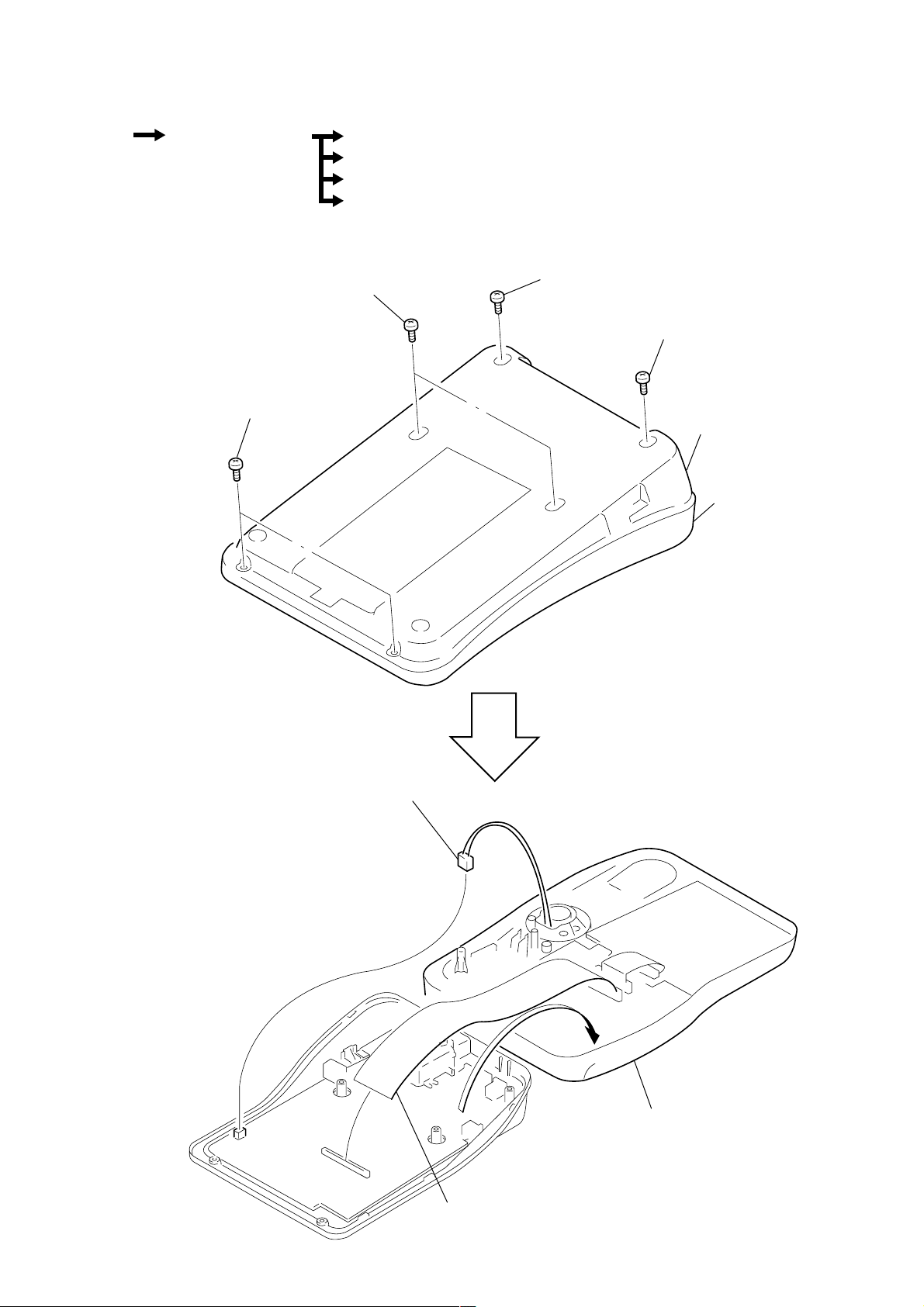
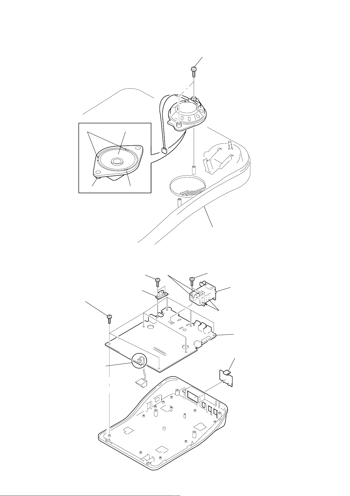
2-1. CABINET (UPPER) ASSY
Cabinet (Upper) Assy Speaker (LS1)
Main Board
Key Board, LCD Board (IT-M704)
Key Board, LCD Board (IT-M804)
3 BTP 3x10
2 BTP 3x10
1 BTP 3x10
4 BTP 3x10
cabinet (lower) assy
cabinet (upper) ass
5 CN9
6 CN6
– 13 –
7 cabinet (upper) assy
Page 14
e
2-2. SPEAKER (LS1)
1 BTP 3x8
2-3. MAIN BOARD
2 claws
holder (speaker)
5 BTP 2.6x6
4 speaker
(LS1)
3 claw
3 BTP 2.6x8
4 cover (jack)
8 claws
cabinet (upper)
2 BTP 2.6x8
9 box (battery)
0 Removal the solder.
7 claws
6 MAIN board
1 lid, battery cas
– 14 –
Page 15
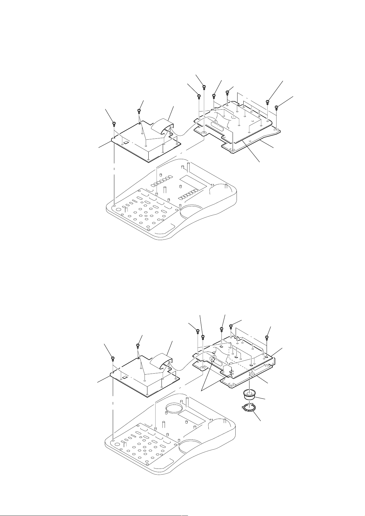
d
6
2-4. KEY BOARD, LCD BOARD (IT-M704)
4 KEY board
3 BTP 2.6x6
0 BTP 2.6x6
2 BTP 2.6x6
1 CN952
5 BTP 2.6x6
6 BTP 2.6x6
9 BTP 2.6x6
8 BTP 2.6x6
7 BTP 2.6x
qa button (one-touch)
qs LCD board
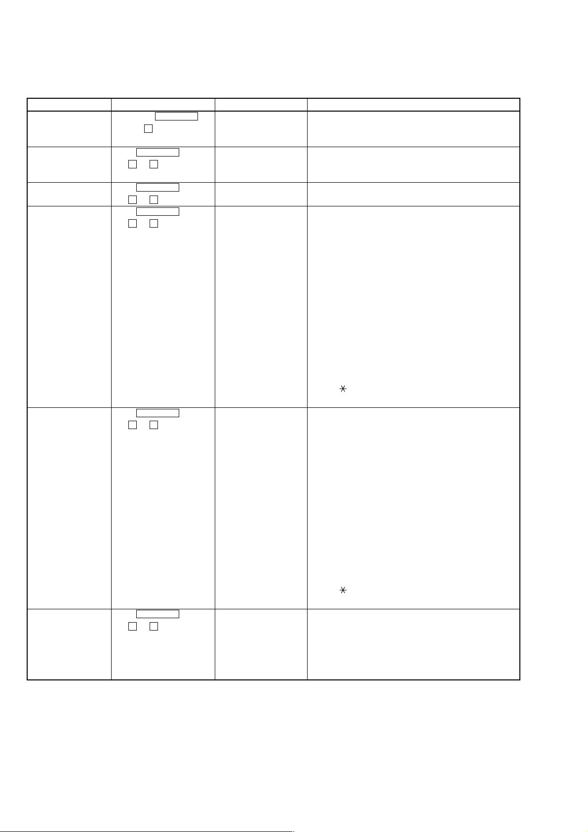
2-5. KEY BOARD, LCD BOARD (IT-M804)
2 BTP 2.6x6
3 BTP 2.6x6
4 KEY board
5 BTP 2.6x6
qa BTP 2.6x6
1 CN952
qs claws
6 BTP 2.6x6
0 BTP 2.6x6
7 BTP 2.6x6
qf LCD boar
qd chassis (M804)
9 jog (dial)
8 guide (jog)
– 15 –
Page 16
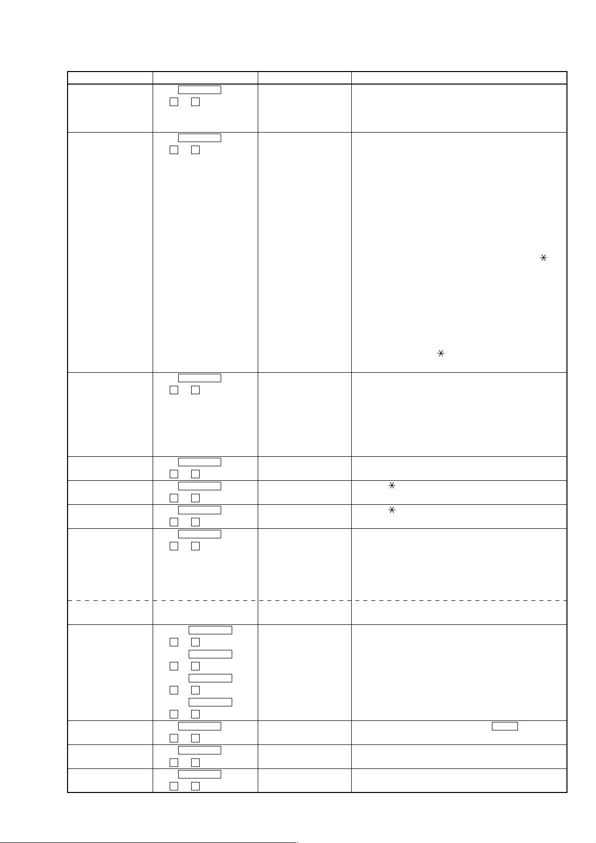
SECTION 3
TEST MODE
This set provides the Test Mode.
When servicing the set, the Test Mode should be performed according to the test items, selecting methods and procedures given below:
Test item Selecting method LCD display Procedures
1) Enter the Test Mode. Hold down PROGRAM TEST MODE Idling state in the Test Mode.
key and 5 key and turn on
the power.
2) LCD test Press PROGRAM 1 All LCD indicators ON.
t 0 t 1 key. 2 All LCD indicators OFF .
1 and 2 are repeated.
3) DATA carrier Press PROGRAM 450 kHz DATA Tx Continuous transmission of carrier signal (450 kHz).
t 0 t 2 key.
4) Intercom call test Press PROGRAM INTERCOM 321 kHz (1) Handset call
(when calling) t 0 t 3 key. (transmit frequency)/ When the handset is hooked off, the extension handset call
*1) MOD TX DATA (when transmit and reception paths are opened. The handset VR is
modulation data is sent) then active and its sound level is displayed.
(2) Headset call
When the headset plug is inserted and then the SPEAKER
press is pressed, the extension handset call transmit and
reception paths are opened. The headphone VR is then
active and its sound level is displayed.
(3) Speaker phone call
When the headset plug is removed and then the SPEAKER
key is pressed, the extension handset call transmit and
reception paths are opened. The SP VR is then active and
its sound level is displayed.
(4) Transmit modulation data ON/OFF
The key is used to start sending the transmit modulation
data. The # key is used to stop sending.
5) Intercom call test Press PROGRAM INTERCOM 281 kHz (1) Handset call
(when called) t 0 t 4 key. (transmit frequency)/ When the handset is hooked off, the extension handset call
*1) MOD TX DATA (when transmit and reception paths are opened. The handset VR
modulation data is sent) is then active and its sound level is displayed.
(2) Headset call
When the headset plug is inserted and then the SPEAKER
press is pressed, the extension handset call transmit and
reception paths are opened. The headphone VR is then
active and its sound level is displayed.
(3) Speaker phone call
When the headset plug is removed and then the SPEAKER
key is pressed, the extension handset call transmit and
reception paths are opened. The SP VR is then active and its
sound level is displayed.
(4) Transmit modulation data ON/OFF
The key is used to start to send the transmit modulation
data. The # key is used to stop to send.
6) Extension data Press PROGRAM MOD. TX DATA The extension data is equivalent to PN 9 and 127 bytes are
transmission t 0 t 5 key. (450 kHz) sent once.
*2) The data is repeatedly sent 5 sec after it has been sent.
Start to send: Hook off the handset or press the SPEAKER key.
Stop to send: Hook on the handset or press SPEAKER key.
450 kHz carrier, transmit data path is opened.
Note:
*1) Each of 4) Extension Call Test (when calling) and 5) Extension Call T est (when called) may be completed by using one set. However , one set at the calling
side and one set at the called side should be used to ensure that these tests can be completed.
*2) 6) Extension Data Transmission may be checked by one set. However, another set should be used at the called side to ensure that this transmission can be
checked.
*3) Another set must be used at the calling side so that 7) Extension Data Reception can be checked.
– 16 –
Page 17
Test item Selecting method LCD display Procedures
7) Extension data Press PROGRAM RX DATA receiving state Waiting state.
reception t 0 t 6 key. display Hook on the handset or press the SPEAKER key.
*3) LCD display: Rx OK = xxx ER = xxx
When the transmit data is received, the display is updated.
8) Key Press PROGRAM Input key: To exit this mode, press the SPK PHONE key twice.
t 0 t 7 key. Press the following buttons in sequence. When the contact is
OK for each key input, a beep sounds to inform that the input
is accepted.
When the last key is pressed, an OK sound is heard.
IT-M804:
(1) OFF HOOK and ON HOOK, (2) JOGDIAL right and left
buttons, (3) ERASE, (4) FLASH, (5) ONE TOUCH 1 to 8,
(6) PROGRAM, (7) LOWER, (8) LINE 1 to 4, (9) INTERCOM,
(10) CONF, (11) TRANSFER, (12) HOLD, (13) ALL PAGE,
(14) PAGE, (15) VOLUME UP and DOWN, (16) 1 to 9, , 0,
and #, (17) REDIAL, (18) BUSY REDIAL, (19) MUTE,
(20) DND, and (21) SPK PHONE
IT-M704:
(1) OFF HOOK and ON HOOK, (2) ERASE, (3) FLASH,
(4) ONE TOUCH 1 to 14, (5) PROGRAM, (6) LOWER,
(7) LINE 1 to 4, (8) INTERCOM, (9) CONF, (10) TRANSFER,
(11) HOLD, (12) ALL PAGE, (13) PAGE, (14) VOLUME UP
and DOWN, (15) 1 to 9, , 0, and #, (16) REDIAL, (17) BUSY
REDIAL, (18) MUTE, (19) DND, and (20) SPK PHONE
9) LED Press PROGRAM LED indicator illuminated The illuminated LED indicator switches very 500 mS.
t 0 t 8 key. and name displayed The name appears at the right of the illuminated LED indicator:
(1) NEW CALL, (2) VMWI, (3) LOWER, (4) LINE1, (5) LINE2,
(6) LINE3, (7) LINE4, (8) INTERCOM, (9) CONF,
(10) BUSY REDIAL, (11) MUTE, (12) DND, (11) SPK PHONE
and (14) OFF
These (1) to (14) LED indicators are illuminated in turn.
10) Bell Press PROGRAM Bell level display RINGER VR can be used to switch the bell level.
t 0 t 9 key. HIGH/MID/LOW/OFF Press the # key to stop the bell..
11) Ring back tone Press PROGRAM RING BACK TONE Press the key to start the ring back tone.
t 1 t 0 key. Press the # key to stop the ring back tone.
12) Key touch tone Press PROGRAM KEY TONE Press the key to start the key tone.
t 1 t 1 key. Press the # key to stop the key tone.
13) LINE connection Press PROGRAM LINE TEST When the handset is hooked off or the SPEAKER key is pressed
t 1 t 2 key. (with the privacy function released), all LINE keys (L1 to L4) are
accepted and the selected lines are all closed. This mode is active
when any of the handset, headset and speaker phone is used.
To release this mode, hook off the handset and press the
SPEAKER key.
D signal send The above test mode LINE TEST D Press ALL PAGE to turn on this mode. Press PAGE to turn off
the mode.
14) FSK detect level, L1: Press PROGRAM L1 CAS TEST (LINE1 ON)
after call incoming t 2 t 1 key.
bell, during call L2: Press PROGRAM L2 CAS TEST (LINE2 ON) Press SPEAKER PHONE to release this mode.
t 2 t 2 key.
L3: Press PROGRAM
t 2 t 3 key.
L4: Press PROGRAM
t 2 t 4 key.
15) STUTTER TONE Press PROGRAM STUTTER TEST When the stutter tone is detected with the LINE1 key held
detect level t 1 t 9 key. down, the message lamp flashes.
16) ROM VERSION Press PROGRAM The ROM version of this set is displayed.
display t 9 t 9 key.
17) Display of security Press PROGRAM SECURITY=
t 8 t 8 key. (Number of four figure)
****
Check to security code called user for phone directory.
– 17 –
Page 18

(
)
L601
Ver 1.1 2000. 07
SECTION 4
ELECTRICAL ADJUSTMENT
ELECTRICAL ADJUSTMENT
The Adjustment method was changed.
4-1. 450kHz DATA RECEIVER ADJUSTMENT
Setting :
1) Connect the oscillator to LINE1 (CN1 (pins 3 and 4)) and set the frequency to 450 kHz (Deviation = OFF).
2) Adjust the output of the oscillator so that the level meter reads out – 61 dBv.
level meter
oscillator
main board
oscilloscope
(TP70)
+
–
450kHz/
–61dBV
Deviation:off
LINE1 (CN1)
set
3
4
GND (TP71)
+
–
Procedure :
1) Turn the core of IFT1 (1
ST IFT) counterclockwise to set the core to the top position (where the core is most off). Verify that TP70 (IC804
1Pin COMP OUT) is at “HIGH” level (approx. 5 V) with the oscilloscope.
2) Slowly turn the core of IFT1 clockwise and stop to turn it at the position where TP70 is at “LOW” (approx. 0 V).
Note : These is no adjustment of IFT2.
Adjutment Location :
– main board (side B) –
L602
TP102
TP103
604
C659
R663
C661
C856
R832
4
C510
C604
TP100
L603
C640
TP112
FL801
L808
R858
C855
R866
IFT2
C884
IFT1
C828
C845
TP81
ZD601
450kHz DATA RECEIVER
ADJUSTMENT
T600
R715
TP111
L803
C803
L802
L809
E C B
IFT1
C625
TP33
C843
R876
C656
C881
Q803
R661
C812
L807
C805
C809
L804
C804C802
TP84
TP113
C883
C860
R828
C826
R830
R890
L801
TP69
TP65
R829
R882
R802
C801
C612
C820
R6
TP68
C823
C858
C844
C867
C822
Q802
E C B
C807
R803
L805
(no adjustment)
C811
C827
C806
IFT2
TP71
D806
R811
R810
31
IC807
45
C817
R879
C888
K
14 8
C808
L806
C606
R613
C611
R607
TP66
R814
R815
R813
R889
A
R816
C813
R818
C814
C816
IC802
17
TP109
R805
R804
C880
TP67
TP110TP74
20 11
IC803
1
C882
TP82
C840
C608
R612
R610
TP26
K
D801
TP70
C726
10
R11
A
C852
TP24
R857
TP46
C842
R627
TP48
TP86
C99
TP31
TP28
R883
R884
C871
R886
R885
C81
L501
C575
TP23
TP47
C545
R719
C574
R665
R740
(M804)
14 8
IC703
17
M804
R12
TP70
R714
TP71
R642
TP25
TP49
TP19
– 18 –
Page 19

SECTION 5
DIAGRAMS
5-1. IC PIN DESCRIPTIONS
• IC1 µPD78078GF-114-3BA (MAIN SYSTEM CONTROL) (MAIN BOARD)
Pin No. Pin Name I/O Pin Description
1 P120/RTP0 I Headset detection input “L” : With Headset, “H” : Without
2 P121/RTP1 O Head/Handset control output “L” : Handset, “H”: Headset
3 P122/RTP2 O H/S tone control output “H” : H/S tone out
4 P123/RTP3 I RX carrier detection input “H” : RX carrier detect
5 P124/RTP4 O LCD control and drive 4 output
6 P125/RTP5 O LCD control and drive 5 output
7 P126/RTP6 O LCD control and drive 6 output
8 P127/RTP7 O LCD control and drive 7 output
9IC— Ground pin
10 X2 — Main clock oscillation (4.5 MHz)
11 X1 — Main clock oscillation (4.5 MHz)
12 VDD — Power supply pin (+5 V)
13 XT2 — Sub clock oscillation (32.768 kHz)
14 XT1/P01 — Sub clock oscillation (32.768 kHz)
15 RESET I Reset input
16 P00/INTP0/T100 I Phone's sixteen control RX data signal input
17 P00/INTP1/T101 I Power failure detection input for AC power
18 P02/INTP2 I Busy tone/stutter tone detection input
19 P03/INTP3 O CID busy control output
20 P04/INTP4 O LCD RS control and drive output
21 P05/INTP5 O LCD RW control and drive output
22 P06/INTP6 O LCD ENABLE control and drive output
23 AVDD — Power supply pin (+5 V)
24 AVREF0 — Power supply pin (+5 V)
25 P10/ANI0 I LINE 1 INUSE detect input
26 P11/ANI1 I LINE 2 INUSE detect input
27 P12/ANI2 I LINE 3 INUSE detect input
28 P13/ANI3 I LINE 4 INUSE detect input
29 P14/ANI4 I LINE 1 RINGER detect input (Normally: “H”)
30 P15/ANI5 I LINE 2 RINGER detect input (Normally: “H”)
31 P16/ANI6 I LINE 3 RINGER detect input (Normally: “H”)
32 P17/ANI7 I LINE 4 RINGER detect input (Normally: “H”)
33 AVSS — Ground pin
34 P130/AN00 O Speaker phone volume conrtol output (Analog output)
35 P131/AN01 O Not used (Open)
36 AVREF1 I Speaker phone volume VB detect input
37 P70/SI2/RXD I RX data input
38 P71/SO2/TXD O TX data output (400 bps)
39 P72/SCK2/ACK O Sub CPU reset signal output
40 VSS — Ground pin
41 P20/SI1 I Sub CPU DO signal input
42 P21/SO1 O Sub CPU DI signal output
43 P22/SCK1 O Sub CPU clock signal output
44 P23/STB O Call ID data ANS signal output
45 P24/BUSY I Call ID data request signal input
46 P25/SI0/SDA0 O EEPROM WP signal output
47 P26/SO0/SDO0 I/O EEPROM serial data signal input/output
48 P27/SCK0/SCL O EEPROM serial clock (64 kBITS) signal output
49 P80/A0 O LINE 1 loop signal output
50 P81/A1 O LINE 2 loop signal output
51 P82/A2 O LINE 3 loop signal output
– 19 –
Page 20

Pin No. Pin Name I/O Pin Description
52 P83/A3 O LINE 4 loop signal output
53 P84/A4 O LINE 1 hold signal output
54 P85/A5 O LINE 2 hold signal output
55 P86/A6 O LINE 3 hold signal output
56 P87/A7 O LINE 4 hold signal output
57 P40/AD0 I Key matrix signal input 0
58 P41/AD1 I Key matrix signal input 1
59 P42/AD2 I Key matrix signal input 2
60 P43/AD3 I Key matrix signal input 3
61 P44/AD4 I Key matrix signal input 4
62 P45/AD5 I Key matrix signal input 5
63 P46/AD6 I Key matrix signal input 6
64 P47/AD7 I Hook switch signal input OFF HK: “L”, ON HK: “H”
65 P50/A8 O Key scan output 0/LED D1 signal output
66 P51/A9 O Key scan output 1/LED D2 signal output
67 P52/A10 O Key scan output 2/LED D3 signal output
68 P53/A11 O Key scan output 3/LED D4 signal output
69 P54/A12 O Key scan output 4/LED D5 signal output
70 P55/A13 O Key scan output 5/LED D6 signal output
71 VSS — Ground pin
72 P56/A14 O Key scan output 6/LED D7 signal output
73 P57/A15 O Key scan output 7/LED D8 signal output
74 P60 O LED expander 1 latch 1 strobe output
75 P61 O LED expander 2 latch 2 strobe output
76 P62 O Handset TX control output
77 P63 O Handset RX control output
78 P64/RD O Intercom control output
79 P65/WR O Intercom handset control output
80 P66/WAIT I Model selection input IT-M804: “L”, IT-M704: “H”
81 P67/ASTB O Power save output POWER OFF: “H”, POWER ON: “L”
82 P100/TI5/TO5 O Control data carrier (450 kHz) output
83 P101/TI6/TO6 O Intercom carrier output Calling: 321 kHz, Called: 281 kHz
84 P102 O R/H VOL1 output ON hook: Ringer volume, OFF hook: Handset volume
R/H VOL2 output ON hook: Ringer volume, OFF hook: Handset volume
VOLUME R/H VOL1 R/H VOL2
85 P103 O
86 P30/TO0 O Pulse dial signal output
87 P31/TO1 O Beep output/Ring back tone output
88 P32/TO2 O Tone generation output D0
89 P33/TI1 O Tone generation output D1
90 P34/TI2 O Tone generation output D2
91 P35/PCL O Tone generation output D3
92 P36/BUZ O Key touch tone output
93 P37 O Tone generation enable output
94 P90 O Speaker amplifier on signal output
95 P91 O Speaker phone RX control output
96 P92 O Speaker phone TX control output
97 P93 O Speaker phone MIC mute
98 P94 O Speaker IC chip disable output IC active: “L”
HI H L
MID L H
LOW H H
STD BY/OFF L L
– 20 –
Page 21

Pin No. Pin Name I/O Pin Description
99 P95 I JOG dial signal input (+)
100 P96 I JOG dial signal input (–)
• IC500 µPD78082GB-B35-3BS-MTX (SUB SYSTEM CONTROL) (MAIN BOARD) (IT-M804 ONLY)
Pin No. Pin Name I/O Pin Description
1 P12/ANI2 — Not used in this set.
2 P13/ANI3 I Call ID RX data-in LINE 1 signal input
3 P14/ANI4 O Call ID data clock LINE 1 signal output
4 P15/ANI5 I Call ID data detection LINE 1 signal input
5 P16/ANI6 I Call ID data request LINE 1 signal input
6 P17/ANI7 O Call ID mode set LINE 1 signal output
7 P72/ASCK/SCK2 I Call ID clock signal input
8 P71/TXD/SO2 O Call ID data output
9 P70/RXD/SI2 I Call ID data input
10 P101/TI6/TO6 I Call ID busy input
11 P100/TI5/TO6 O FSK/CAS select control output “H”: FSK, “L”: CAS
12 P50 I Call ID RX data-in LINE 2 signal input
13 P51 O Call ID data clock LINE 2 signal output
14 P52 I Call ID data detection LINE 2 signal input
15 P53 I Call ID data request LINE 2 signal input
16 P54 O Call ID mode set LINE 2 signal output
17 VSS — Ground pin
18 P55 I Call ID RX data-in LINE 3 signal input
19 P56 O Call ID data clock LINE 3 signal output
20 P57 I Call ID data detection LINE 3 signal input
21 P30 I Call ID data request LINE 3 signal input
22 P31 O Call ID mode set LINE 3 signal output
23 NC — Not used. (Connect to ground in this set.)
24 P32 I Call ID RX data-in LINE 4 signal input
25 P33 O Call ID data clock LINE 4 signal output
26 P34 I Call ID data detection LINE 4 signal input
27 P35/PCL I Call ID data request LINE 4 signal input
28 P36/BUZ O Call ID mode set LINE 4 signal output
29 P37 — Not used in this set.
30 P00 I LINE 1 loop detection signal input
31 P01/INTP1 O Call ID data request signal output
32 P02/INTP2 I Call ID data ANS signal input
33 P03/INTP3 I LINE 2 loop detection signal input
34 NC — Not used. (Connect to ground in this set.)
35 RESET I Reset signal input
36 VPP — Ground pin
37 X2 — System clock ocsillation pin (3.58 MHz)
38 X1 — System clock ocsillation pin (3.58 MHz)
39 VDD —
40 AVDD — Power supply pin (+ 5 V)
41 AVREF —
42 AVSS — Ground pin
43 P10/ANI0 I LINE 3 loop detection signal input
44 P11/ANI1 I LINE 4 loop detection signal input
– 21 – – 22 –
Page 22

IT-M704/M804
5-2. BLOCK DIAGRAM — MAIN (1) SECTION —
MAIN BOARD (1/3)
(MAIN(1) SECTION)
CN1
LINE1
LINE1+2
1
2
3
4
5
6
CN2
LINE3
LINE3+4
1
2
3
4
5
6
CN3
DATA
L2
L3
1
2
L4
3
4
5
6
SW2
DATA LINE SELECT
F101
F201
F301
F401
SG101
SG201
SG301
SG401
T100
RF
FILTER
T801
RF LINE
TRANSFORMER
T200
RF
FILTER
T300
RF
FILTER
T400
RF
FILTER
RING DETECT
PH101
IC505(1/4)
RECT
DB101
RING DETECT
PH201
IC505(2/4)
RECT
DB201
RING DETECT
PH301
IC505(3/4)
RECT
DB301
RING DETECT
PH401
IC505(4/4)
RECT
DB401
M804
IC101(4/4)
LOOP/CONTROL
Q905,910,RT5
RY1
M804
IC101(3/4)
LOOP/CONTROL
PH902,Q902,906
RY2
M804
IC101(2/4)
LOOP/CONTROL
PH903,Q903,907
RY3
M804
IC101(1/4)
LOOP/CONTROL
PH904,Q904,908
RY4
HOLD
RELAY
CONTROL
HOLD
RELAY
CONTROL
HOLD
RELAY
CONTROL
HOLD
RELAY
CONTROL
LIRING
LIUSE
P DIAL
450kHz
TX DATA
RX DATA
L1RING
L2RING
L3RING
L4RING
L1USE
L2USE
L3USE
L4USE
L1HD
L2HD
L3HD
L4HD
L1LP
L2LP
L3LP
L4LP
MAIN SYSTEM CONTROL
IC1(1/3)
86
P30/T00
P100/TI5/T06
82
P71/S02/TXD
38
83
P101/TI6/T06
4
P123/RTP3
P00/INTP0/T100
16
37
P70/SI2/RXD
P14/ANI4
29
P15/ANI5
30
31
P16/ANI6
P17/ANI7
32
25
P10/ANI0
26
P11/ANI1
P12/ANI2
27
P13/ANI3
28
53
P84/A4
P85/A5
54
P86/A6
55
P87/A7
56
P80/A0
49
P81/A1
50
P82/A2
51
P83/A3
52
LIHD
AF LINE
TRANSFORMER
AF LINE
LOOP/CONTROL
PH601,Q601,602
L1LP
Q2
L2RING
L2USE
L2HD
L2LP
Q3
L3RING
L3USE
L3HD
L3LP
Q4
L4RING
L4USE
H4HD
L1
L2
L3
L4
AM
MODULATOR
IC5
AM
MODULATOR
Q801,802
RX DATA
DE-MODULATOR
Q803
SYSTEM
CONTROL
C
SECTION
(Page 27)
IC807
IC801(1/2)
IFT1 IFT2
AF
AGC
26dB AMP
IC801(2/2)
RX DATA
DE-MODULATOR
450kHz DATA
RECEIVER
• Signal path
Q804
IFT1, 2
MAIN(2)
A
SECTION
(Page 25)
AMP
IC802(4/4)
DET
D802
AMP
Q805
SHOT KEY
D806
LPF AMP
IC802(2/4)
AMP
IC802(1/4)
LPF AMP
IC802(3/4)
EPI
FO
DET
D804
COMPARATOR
IC804(2/2)
MAIN(2)
B
SECTION
(Page 25)
COMPARATOR
IC804(1/2)
321/281kHz
RX CAR DET
: TX(To Tel line)
: RX(From Tel Line)
: Bell
L4LP
Q5
L1LP
L2LP
L3LP
L4LP
D
(Page 27)
SYSTEM
CONTROL
SECTION
04
– 23 – – 24 –
Page 23

5-3. BLOCK DIAGRAM — MAIN (2) SECTION —
IT-M704/M804
MAIN BOARD (2/3)
(MAIN(2) SECTION)
MAIN(1/2)
SECTION
(Page 24)
X601
3.58MHz
A
AF
DIMF
GENERATOR
IC603
TONE OUT
OSCIN
6
7
OSCOUT
MAIN(1)
SECTION
(Page 24)
14
8
MUTE
9
D0 P02/INTP2
D1
10
D2
11
D3
12
2
TEN
B
MUTE
Q617
FO
EPI
SPEECH N/W
IC601
MIC+
10
MIC-
1
7
DIMF
5
MUTE
6
MAIN SYSTEM CONTROL
IC1(2/3)
P63
P91
P62
P92
AVREF1
P94
P93
P90
P64/RD
BUSY/ST DET
18
INTHS
79
HSRXM
77
SPRX
95
HSTXM
76
SPTX
96
H/S TONE CONT
3
BEEP OUT
87
SPVB
36
SPCD
98
SPMIC MUTE
97
SPVOLCONT
34
KEY TONE
92
SPA
94
HEAD/S DET
1
HEAD/S CONT
2
INT
78
88
P32/T02
89
90
91
93
P33/TI1
P34/TI2
P35/TI3
P37
P65/WR
P122/RTP2
P31/T01
P130/ANO0
P36/BUZ
P120/RTP0
P121/RTP1
FILTER AMP
15 19
9
12
BUSY/STUTTER
TONE DETECT
5
1
2
COMPRESSOR
3 8
21
SUMMING
AMP
MUTE
D801
X602
3.58MHz
SIGIN
XTAL
XTALN
IC605
DET
EXPANDOR/COMPANDER
CMUTE
11
13
EMUTE
EXPANDOR
4
IC803
INTERCOM
HANDSET
CONTROL
Q609
HSTXM
SPTX
HSRXM
SPRX
ANALOG SWITCH
IC703
2
13
9
6
4
5
11
12
1
8
3 5
10
ANALOG SWITCH
IC806(1/2)
3
9
C
TONE CONTROL
Q616
SPEAKER PHONE
&
SP VR CONT
IC701
TAO
23
4
TLI
15
RAI
RXO
16
17
RXI
PLI
11
6
VB
CD
8
18
MUTE
VLC
19
XDI
TAI
MCI
MCO
RAO
MIC AMP
(HEADSET)
IC612
MIC AMP
(HANDSET)
IC606
4
2
22
20
21
14
Q613
REC VOLUME,
RING VR CONT
IC602
X2 X
15 13
X1
14
X0
12
X3
11
Y
Y2
2
4
Y3
Y1
5
SP ON/OFF
SWITCH
3
Q702
AMP
IC604
• Signal path
: TX(To Tel line)
: RX(From Tel Line)
Q611
Q615
SPEAKER AMP
IC702
Q614
1
2
3
4
5
1
2
1
2
CN7
HANDSET
CN5
CN9
CN10
I
HANDSET
MIC2
MIC
LS1
(SPEAKER)
: Bell
04
– 25 – – 26 –
Page 24

IT-M704/M804
5-4 BLOCK DIAGRAM — SYSTEM CONTROL SECTION —
MAIN BOARD (3/3) LCD BOARD
(SYSTEM CONTROL SECTION)
DECODER(LINE1)
1
2
5
DECODER(LINE2)
1
2
5
6
DECODER(LINE3)
1
2
5
6
DECODER(LINE4)
1
2
5
6
04
MAIN(1)
SECTION
(Page 24)
C
ANALOG SWITCH
IC806(2/2)
L1
L2
L3
L4
12
ANALOG SWITCH
12
X
OX
A
B
IC805
OZ
5
Z
OY
2
Y
OX
X
A
B
C
X501
3.58MHz
14 6
11
10
X502
3.58MHz
4
X503
3.58MHz
15
X504
3.58MHz
14
11
10
9
CAS F.S.K
IC501
XTALN
XTAL
ADP
INV
CAS F.S.K
IC502
XTALN
XTAL
ADP
INV
CAS F.S.K
IC503
XTALN
XTAL
ADP
INV
CAS F.S.K
IC504
XTALN
XTAL
ADP
INV
L4LP
L3LP
L2LP
L1LP
RXD
RXCK
DET
IRQN
MODE
RXD
RXCK
DET
IRQN
MODE
RXD
RXCK
DET
IRQN
MODE
RXD
RXCK
DET
IRQN
MODE
15
14
13
12
10
FSKSEL
15
14
13
12
10
15
14
13
12
10
15
14
13
12
10
MAIN(1)
D
SECTION
(Page 24)
C1R
C1C
C1D
C1I
C1M
L1LP
C2R
C2C
C2D
C2I
C2M
C3R
C3C
C3D
C3I
C3M
C4R
C4C
C4D
C4I
C4M
L4LP
L3LP
L2LP
M804
SUB SYSTEM CONTROL
IC500
PI3/ANI3
2
PI4/ANI4
3
PI5/ANI5
4
PI6/ANI6
5
PI7/ANI7
6
P00
30
P100/TI5/TO5
31
P50
12
P51
13
P52
14
P53
15
P54
16
18
P55
P56
19
20
P57
21
P30
22
P31
P32
24
P33
25
P34
26
P35/PCL
27
PP35/BUZ
28
44
P11/ANI1
P10/ANI0
43
P03/INTP3
33
P72/ASCK/SCK2
P71/TXD/SO2
P70/RXD/SI2
P101/TI6/TO6
P01/INTP1
P02/INTP2
RESET
SW4
(HOOK)
KI0
KI1
KI2
KI3
KI4
KI6
KI5
KS0
KS1
KS2
KS3
KS4
KS5
KS6
KS7
4.5MHz
32.768kHz
X1
X2
5
6
7
M804
EEPROM
SDA
SCL
WP
RESET
IC2
D1
D6
IC3
CN6 CN951
LCD4
LCD5
LCD6
LCD7
LCDRS
LCDRW
LCDE
SW1
RESET
VDD
KI0
KI1
KI2
KI3
KI4
KI6
KI5
KS0
KS1
KS2
KS3
KS4
KS5
KS6
KS7
CN8
9V REG
Q9
29
28
27
26
24
23
22
25
4
3
20
19
18
17
16
14
15
12
11
10
9
8
7
6
5
31
32
1
2
3
1
2
LCD4
29
LCD5
28
LCD6
27
LCD7
26
LCDRS
24
LCDRW
23
LCDE
22
RESET RESET
25
LED0
4
LED1
3
KI0
20
KI1
19
KI2
18
KI3
17
KI4
16
KI6
14
KI5
15
12
11
10
9
8
7
6
5
31
32
KS0
KS1
KS2
KS3
KS4
KS5
KS6
KS7
JOG-
JOG+
M804
DC IN 12V
M704
CN4
M704
KI4,6
KI5
!
DRY BATTERY
9V
(IEC DESIGNATION 6F22)
LED0
RESET
LED1
KS0-7
KEY MATRIX
IT-M704:
SW951-963,
965-969
IT-M804:
SW951-963
VDD
KS0
KS1
KS2
KS3
KS4
KS5
KS6
KS7
KS0
KS1
KS2
KS3
KS4
KS5
KS6
KS7
VDD
LCD DRIVE
42
VDD
LCD4
47
48
LCD5
49
LCD6
50
LCD7
LCDRS
39
LCDRW
40
41
LCDE
LED DRIVE
CLR
1
D1
3
D2
4
D3
7
D4
8
D5
13
14
D6
D7
17
D8
18
CK
11
LED DRIVE
1
CLR
3
D1
4
D2
7
D3
8
D4
13
D5
14
D6
17
D7
18
D8
11
CK
IC951
IC952
IC953
JOG+
JOG-
Q1
Q2
Q3
Q4
Q5
Q7
Q8
Q6
Q1
Q2
Q4
Q3
Q5
LINE1
2
LINE2
5
LINE3
6
LINE4
9
INT
12
SPK
16
B-DIAL
19
15
CONF
1
DND
3
MUTE
4
6
12
LED951
MESSAGE
JOG DIAL
LIQUID CRYSTAL
DISPLAY PANEL
LCD951
LED952
LOWER
SW904
M804
M804
LED953
NEW CALL
B-DIAL
KS0-7
MUTE
LINE4
LINE3
DND
SPK
INT
LINE1
CONF
LINE2
KI0-3
KEY BOARD
CN11CN952
BUSY REDIAL
1
1
2
3
4
5
6
7
8
9
10
21
I
24
12
I
19
MUTE
2
LINE4
3
LINE3
4
DND
5
SPEAKER PHONE
6
INTERCOM
7
LINE1
8
CONFERENCE
9
LINE2
10
21
KI0-3
I
24
12
KS0-7
I
19
LED
LED100-109
KEY MATRIX
SW100-115,
118-125,
127-131
MAIN SYSTEM CONTROL
IC1(3/3)
P26/S00/SD00
P27/SCKO/SCL
P25/SI0/SDI0
CICL
7
CIDO
8
CIDI
9
CIRQ
CIAN
RESET
X505
3.58MHz
M704
M804
VDD
5.4V
5.3V
CIB
B+
6V
6V
10
31
37X2
38X1
D11
D13
D2
P22/SCK1
43
P20/SI1
41
P21/SO1
42
P03/INTP3
19
P24/BUSY
45
P23/STB
4432
P72/SCK2/ASCK
3935
P66/WAIT
80
P67/ASTB
81
17
P01/INT1/T101
6V REG
Q10
M704
P124/RPT4
P125/RPT5
P126/RPT6
P127/RPT7
P05/INTP5
P06/INTP6
P47/AD7
P41/AD1
P42/AD2
P43/AD3
P44/AD4
P46/AD6
P45/AD5
P50/A8
P51/A9
P52/A10
P53/A11
P54/A12
P55/A13
P56/A14
P57/A15
P95
XT1
POWER DOWN
POWER DOWN
X2
X1
X2
47
48
46
5
6
7
8
20P04/INTP4
21
22
64
15RESET
74P60
75P61
57P40/AD0
58
59
60
61
63
62
65
66
67
68
69
70
72
73
100P96
99
10
11
13
14
9.4V
REG
IC4
DETECT
Q1
DETECT
Q6,7,8
– 27 – – 28 –
Page 25

IT-M704/M804
THIS NOTE IS COMMON FOR PRINTED WIRING
BOARDS AND SCHEMATIC DIAGRAMS.
For Schematic Diagram:
• All capacitors are in µF unless otherwise noted. pF: µµF
50 WV or less are not indicated except for electrolytics
and tantalums.
• All resistors are in Ω and 1/
specified.
f
•
• 2 : nonflammable resistor.
• C : panel designation.
Note: The components identified by mark 0 or dotted line
• U : B+ Line.
• Power voltage is dc 12 V and fed with regulated dc power
• Power voltage is dc 12 V and fed with regulated dc power
• Voltage and waveforms are dc with respect to ground
• Voltages are taken with a VOM (Input impedance 10 MΩ).
• Waveforms are taken with a oscilloscope.
• Circled numbers refer to waveforms.
• Signal path.
For Printed Wiring Boards:
• X : parts extracted from the component side.
•
•
• : carbon pattern
• b : Pattern from the side which enables seeing.
Caution:
Pattern face side: Parts on the pattern face side seen from the
(Side B) pattern face are indicated.
Parts face side: Parts on the parts face side seen from the
(Side A) parts face are indicated.
: internal component.
with mark 0 are critical for safety.
Replace only with part number specified.
supply from external power voltage jack.
supply from CN1 with 100 Ω in series (LINE1).
under no-signal (detuned) conditions.
no mark : Hook off (Talk)
( ) : Hook on
Voltage variations may be noted due to normal production tolerances.
Voltage variations may be noted due to normal production tolerances.
N : TX (To Tel Line)
O : RX (From Tel Line)
P : bell
(The other layer’s patterns are not indicated.)
: Impossible to measure
∗
z
: Through hole.
f
: internal component.
4
W or less unless otherwise
• Waveforms
1
2
3
4
5
0.1V/div 0.5µsec/div
3.58MHz
IC501
IC502
IC503
IC504
0.1V/div 0.5µsec/div
4.5MHz
IC1
0.1V/div 50msec/div
32.768kHz
IC1
0.1V/div 0.5µsec/div
3.58MHz
IC500
0.1V/div 0.5µsec/div
3.58MHz
IC605
(XTALN)
1
(XTALN)
1
(XTALN)
1
(XTALN)
1
(X2)
q;
(XT2)
qd
ej
(XTALN)
2
4Vp-p
5Vp-p
5.2Vp-p
5.4Vp-p
(X2)
4Vp-p
– 29 – – 30 –
Page 26

IT-M704/M804
5-5. PRINTED WIRING BOARD — MAIN SECTION — • Refer to page 29 for Note.
A
B
C
D
E
F
G
H
J
1
2 3 4 5 6 7 8 9 10 11 12 13 14
CN10
MAIN BOARD (SIDE A)
I
• Semiconductor
Location (SIDE A)
Ref. No. Location
C715
R737
R703
C741
C742
R736
C708
C707
24 13
112
R705
C537
C519
R738
IC701
C709
C710
C536R553
16 9
IC504
18
C544
R551
16 9
IC503
18
R552
16 9
IC502
18
R523
C518
C517R522
R728
C534
R545
R546
C535
C527
C714
R668
ECB
R631
R635
R637
R697
C525
R533
R534C526
ECB
Q613
16 9
Q616
1816
C505
IC501
18
R511
R510
C508
C516
R649
IC602
9
M804
ECB
Q617
R621R616
C849
R831
C863
C857
D603
R789
PH601
4
12
C97
7
8
C616
C654
R850
A
K
C839
R873
R851
C846
3
R611
IC601
C613
R821
C815
R817
R819
C872
R846
C848
C615
C838
R847
C836
1
14
R615
C617
D802
C850
R617
C618
C837
R853
C619
R614
R667
C868
C825
C818
R827
R822
R845
R658
C614
R877
C607
R608
R681
ECB
R659
Q609
D803
R891
C824
IC801
C886
C821
R888
Q4
R887
R806
ECB
R807
C810
R808
R27
R826
C869
14 8
17
Q801
ECB
K
D9
A
IC804
C80R863
85
4
1
R865
R864
R843
R844
R862
C853
Q805
C894
R841
R860
C892
R840
R91
R82
R84
C854
D804
ECB
R5
R83
C851
R837
R838
R848
R849
R842
R862
ZD3
R834
R839
C829
R701
C833
C847
A
A
A
K
D502
R859
C832R854
M804
D508
D507
R856
C830
ECB
Q804
K
K
IC606
R836
C660
14
85
C893
R833
R664R623
R538
C506
R509
R503
A
A
C533
R542
14 8
17
R537
R502
R515
R526
D501
D504
IC505
R514
R525
K
K
C515
R521
R543
R530
R532
R519
K
K
K
R507
C524
M804
D505
D506
A
D503
A
L605
R761
ECB
Q611
R754
R751
Q1
ECB
R14C7R17
K
R88
D4
R89
D807
K
Q9
ECB
R95
R20
A
R13
A
A
Q6
ECB
Q7
ECB
R96
Q8
ECB
R92
R19
R98
R99
C5
IC4
R15
R16
15
L3
16 9
IC806
18
16 9
IC805
18
R666
R669
R671
R641
R638
R696
C637
R636
C509R550
C610 C609R609 C605
C864
R874
C655
C841 R872
R780
D4 D-11
D9 F-7
(D501) F-10
(D502) F-9
(D503) F-10
(D504) F-10
(D505) F-10
(D506) F-10
(D507) F-9
(D508) F-9
D603 D-6
D802 C-6
D803 C-6
D804 C-8
D807 D-11
IC2 I-3
IC3 I-4
IC4 E-12
(IC501) E-4
(IC502) F-3
(IC503) E-3
(IC504) D-3
(IC505) E-10
IC601 B-6
IC602 D-4
IC606 C-9
IC701 C-3
IC801 D-7
IC804 C-7
IC805 B-5
IC806 B-5
PH101 J-7
PH201 I-7
PH601 F-6
PH902 H-7
PH903 G-7
PH904 H-6
Q1 D-12
Q4 F-7
R855
C34
C35
C36
C37
R408
R406
R414
R213
C405
R41
R208
C205
R413
C38
R214
R411
C39
C212
R314
C412
C40
R211
R206
C312
R311
R114
C105
R111
C112
R108
R113
R313
R308
R910
R306
C305
R106
EBC
R917
Q910
R29
R23
Z07
C33
C15
R37
M804
R44
R654
R90
R38
R21
85
IC3
14
C41
M704
R8
C21
R770
R32
I
04
IC2
R31
C18
C19
C8
C17R2
R942
R941
C103
PH904
4
3
12
PH101
2
1
34
R933
C303
R304
R923
C203
43
1
PH201
1
2
PH903
1
2
R207
2
PH902
R202
4
3
R104
R932
4
3
R205
R922
R921
1-673-764-
12
(12)
Q6 E-11
Q7 E-11
Q8 E-11
Q9 E-11
Q609 B-7
Q611 B-11
Q613 B-3
Q616 D-3
Q617 B-5
Q801 C-7
Q804 D-9
Q805 C-8
Q910 I-6
ZD3 B-8
ZD7 H-4
( ) : IT-M804 only
– 31 – – 32 –
Page 27

• Refer to page 29 for Note.
IT-M704/M804
• Semiconductor
Location (SIDE B)
Ref. No. Location
D1 D-12
D2 C-11
D3 D-9
D5 D-9
D6 D-11
D7 I-5
D8 H-7
D10 H-6
D11 D-9
D602 B-11
D801 D-6
D806 B-7
D910 I-6
DB101 I-7
DB201 H-8
DB301 G-8
DB401 G-6
IC1 H-4
IC5 F-5
IC101 J-5
(IC500) E-4
IC603 I-4
IC604 B-11
IC605 F-3
IC702 B-3
IC703 C-5
IC802 C-6
IC803 D-6
IC807 D-7
PH301 G-7
PH401 H-6
Q2 J-6
Q3 H-7
Q5 H-6
Q10 D-11
Q601 F-6
Q602 F-7
Q612 C-10
Q614 C-10
Q615 C-10
Q702 B-3
Q802 D-7
Q803 E-8
Q902 H-9
Q903 G-8
Q904 F-6
Q905 I-6
Q906 G-9
Q907 F-8
Q908 F-6
ZD1 C-11
ZD5 D-10
ZD6 H-6
ZD601 E-9
ZD801 H-9
ZD802 H-9
( ) : IT-M804 only
DRY BATTERY
9V
(IEC DESIGNATION 6F22)
CN4
DC IN 12V
!
CN2
LINE3/
LINE3+4
CN1
LINE1/
LINE1+2
04
234567891011121314
CN7
HANDSET
C640
C855
R866
ZD601
L602
TP112
L808
R858
C884
C828
TP81
Q907
Q903
R925
C925
DB201
14
23
C201
T100
1234
TP102
TP100
L603
FL801
IFT2
IFT1
C845
R931
R934
T600
R935
TP56
R926
R715
TP111
L803
C803
L802
L809
M804
SW1
RESET
C625
C656
TP33
C881
C843
E C B
R876
R936
C935
DB301
43
12
TP53
R201
C502
C501
C812
L807
C809
L804
C804C802
Q803
TP63
R661
TP84
TP113
C805
C860
2
3
RY2
C883
L801
PH301
C301
A
TP54
R828
C826
R830
R890
C603
K
D8
C101
TP65
R802
C801
1
4
C915
TP51
TP69
C612
R829
R882
C602
C302
R301
BCE
R25
C858
C820
Q802
R803
TP57
R302
Q3
R6
TP68
C844
C822
E C B
RY3
R326
R305
C403
DB101
43
1
C823
C867
C807
L805
R605
R327
TP1
2
R102
R101
C606
TP71
K
D806
A
R811
R810
14 8
C811
IC802
17
31
IC807
C827
45
C817
TP109
R805
R879
C888
R804
C808
C880
C806
L806
Q602 Q601
C601
R604
R606
TP62
Q904
C401
DB401
14
23
R307
R401
R402
21
R943
3
PH401
R916
TP501
4
KAA
R915
R914
R105
R404
R204
R613
C611
R607
TP66
R814
R815
R813
R889
R816
C813
R818
C814
C816
TP67
TP110TP74
20 11
IC803
1
C882
R601
Q908
R944
R945
R405
C945
TP59
TP60
R407
RY4
K
D10
ECB
RY5
TP55
D910
RY1
R107
TP82
C840
Q5
TP26
K
D801
R602
R946
TP58
TP52
Q905
BCE
Q2
C608
R612
R610
C726
10
R622
TP64
R603
ZD6
D7
K
R11
A
C852
C623
A
TP24
R857
TP46
C842
33
29
19
9
1
CN6
TP48
TP86
C99
TP83
30
20
10
2
TP8
TP5
TP31
TP28
R883
R884
C871
R627
R886
R885
C81
(M804)
R719
14 8
IC703
17
TP23
M804
TP47
R12
L501
C575
C545
C574
TP70
L1
TP72
R861
TP40
R52
IC101
TP43
R57
R80
TP7
C819
IC5
R51
R22
50
51
TP61
13
54
C96
TP6
R880
14 8
17
R665
R740
TP19
TP4
TP3
R40
60
R124
R714
R632
R642
TP25
TP49
TP20
C83
40
R618
R647
12
CN9
C711
R512
R571
C576
R97
C16
TP2
70
R79
R653
C104
TP77
RED
BLK
C731 R726
TP108
R725
C721
R717
TP107
C720
R710
C732
C740
TP27
C705
C702
C730
C646
TP90
R707
C701
TP89
TP32
C639
C635
X505
C546
3334
44
IC500
1
12
11
TP21
C628
R50
30
IC1
R59
R60
R87
80
TP79
IC603
4
X602
X2
TP42
TP73
20
81
C10
R624
R58
31
TP39
14 8
17
C645
R670
C717
4
IC702
5
R731
R706
C712
R648
C542
TP15
X501
IC605
C11
R4
R3
X1
10
90
TP80
1-673-767-
1
8
TP87
C638
R646
TP76
23
22
C13
C14
1
100
TP75
Q702
85
X601
ECB
C716
TP106
R708
TP30
C12
TP41
C713
TP22
C9
R732
R733
TP16
C626
TP104
C724
C704
TP29
TP17
R34
TP92
R711
C703
R735
(12)
C725R716
TP91
TP14
TP13
X504
TP18
C507
X502
R35
R713
CN5
TP105
12
R33
R36
TP88
C706
X503
M804
C722
1
2
1
(Page 44, 48)
RED
BLK
LCD BOARD
CN951
RED
BLK
MAIN BOARD (SIDE B)
C652
R651
R750
R699
R645
R694
TP99
85
IC604
14
C643
SW4
(HOOK)
ZD1
R643
C4
C3
F301
SG201
F101
-2
-1
L4 L3 L2
DATA LINE SELECT
C642
R644
-1
-2
C29
E C B
Q10
SW2
C649
R762
TP94
C748
D2
TP12
TP11
SG301
L302
L201
SG101
D602
R752
R773
R757
R772
C746
R756
C6
TP10
F401
L301
L102
F201
L101
TP95
C636
C644
C1
C2
D6
D1
C23
BLK
RED
L6
L2
TP35
C22
L4
L5
TP36
1
2
3
4
5
6
1
2
3
4
5
6
R30
C996
C98
L202
R26
L607
C744
BCE
C747
C745
R771
TP9
SG401
L402
T300
T200
T801
R24
R755
Q612
DATA
TP98
R628
Q615
R758
CN3
R753
BCE
C891
TP45
TP96
R662
R760
TP97
TP34
L401
R801
TP93
L606
C658
C743
BCE
TP101
Q614
C781
R782
R759
D3
D11
D5
ZD5
R508
RED
TP37
T400
M804
C522
C512
C513
L811
21345
BLK
CN8
C521
C641
R506
12
TP78
C653
C627
M804
TP38
TP44
C865
6
TP103
L604
C661
C856
C504
C530
C531
ZD801
ZD802
L810
L601
C659
R663
R832
C510
C604
M804
Q906
R924
Q902
C866
1
A
LS1
(SPEAKER)
B
C
D
E
F
G
MIC2
MIC
H
I
J
– 33 – – 34 –
Page 28

IT-M704/M804
5-6. SCHEMATIC DIAGRAM — MAIN (1/3) SECTION — • Refer to page 57 for IC Block Diagrams. Refer to page 29 for Waveforms. Refer to page 29 for Note.
(Page 37)
(Page 37)
(Page 39)
(Page 37)
(Page 39)
– 35 – – 36 –
Page 29

5-7. SCHEMATIC DIAGRAM — MAIN (2/3) SECTION — • Refer to page 57 for IC Block Diagrams. Refer to page 29 for Waveforms. Refer to page 29 for Note.
IT-M704/M804
(Page 36)
(Page 39, 40)
(Page 42, 52)
(Page 39, 40)
(Page 36)
(Page 40)
(Page 40)
– 37 – – 38 –
Page 30

IT-M704/M804
5-8. SCHEMATIC DIAGRAM — MAIN (3/3) SECTION — • Refer to page 58 for IC Block Diagrams. Refer to page 29 for Waveforms. Refer to page 29 for Note.
(Page 37, 38)
(Page 37, 38)
(Page
36)
(Page
38)
(Page
(Page 38)
36)
(Page
37, 38)
(Page 38)
– 39 – – 40 –
Page 31

5-9. SCHEMATIC DIAGRAM — LCD SECTION (IT-M704) — • Refer to page 58 for IC Block Diagrams. Refer to page 29 for Note.
IT-M704/M804
(Page 38)
(Page 54)
– 41 – – 42 –
Page 32

IT-M704/M804
5-10. PRINTED WIRING BOARD — LCD SECTION (IT-M704) — • Refer to page 29 for Note.
A
B
C
D
1
2345678910
LCD BOARD (SIDE A)
SEG1
(M1)
(M2)
LIQUID CRYSTAL DISPLAY PANEL
LCD951
COM1
SEG57
SEG40
LED951
MESSAGE
ERASE/CLEAR
FLASH
(M8)
(M9)
E
F
G
H
(M3)
(M4)
(M5)
CN951
(M6)
(M7)
PROGRAM
I
04
1 2
MAIN BOARD
CN6
(Page 34) (Page 56)
2024
1923
CN952
10
9
KEY BOARD
CN11
191933
2102032
2
1
LED952
LOWER
(M10)
(M11)
(M12)
(M13)
(M14)
1-673-767-
11
(11)
J
– 43 – – 44 –
Page 33

• Refer to page 29 for Note.
IT-M704/M804
R968
R969
R970
LCD BOARD (SIDE B)
R967
C959
10
IC953
11
1
20
C955
C952
ZD951
C951
C953
C954
R953
R952
R957
R958
R955
R956
R954
R951
2345678910
1
A
B
C
D
31
30
R964
R963
R959
R960
R961
R962
R966
C957
C960 C956
110
IC952
11
20
C958
50
51
IC951
1
100
81
80
E
F
G
H
R971
11
04
1-673-767-
(11)
I
J
– 45 – – 46 –
Page 34

IT-M704/M804
5-11. PRINTED WIRING BOARD — LCD SECTION (IT-M804) — • Refer to page 29 for Note.
A
B
C
D
1
2345678910
LCD BOARD (SIDE A)
SEG1
COM1
SEG40
LCD951
LIQUID CRYSTAL DISPLAY PANEL
SEG59
E
F
G
H
ERASE/CLEAR
FLASH
(M1)
(M2)
(M3)
(M4)
PROGRAM
I
33
32
24
23
1 2
MAIN BOARD
CN6
(Page 34) (Page 56)
CN951
CN952
KEY BOARD
CN11
1919
21020
21020
1919
LED953
LED952
LOWER
LED951
MESSAGENEW CALLCALL WAITING/
(M5)
(M6)
(M7)
(M8)
1-673-776-
11
(11)
J
– 47 – – 48 –
Page 35

• Refer to page 29 for Note.
IT-M704/M804
LCD BOARD (SIDE B)
JOG DIAL
SW960
(JOG )
R972
SW964
ROTARY
ENCODER
C955
R953
R952
ZD951
C952
R954
R951
R955
R957
R958
R956
C951
2345678910
1
A
B
1
100
81
80
30
31
C954
C953
IC951
51
50
C
D
R970
R961
R966
R962
R965
R969
R960
C957
R963
R968
10
11
R964
IC952
R959
R967
1
20
C958
10
IC953
11
C959
1
C956C960
20
E
F
G
H
R971
11
04
1-673-766-
(11)
I
J
– 49 – – 50 –
Page 36

IT-M704/M804
5-12. SCHEMATIC DIAGRAM — LCD SECTION (IT-M804) — • Refer to page 59 for IC Block Diagrams. Refer to page 29 for Note.
(Page 38)
(Page 54)
– 51 – – 52 –
Page 37

5-13. SCHEMATIC DIAGRAM — KEY SECTION — • Refer to page 29 for Note.
IT-M704/M804
(Page 41, 51)
– 53 – – 54 –
Page 38

IT-M704/M804
5-14. PRINTED WIRING BOARD — KEY SECTION — • Refer to page 29 for Note.
A
B
C
D
1
2345678910
DISPLAY BOARD
2
CN952
LED100
LINE 1
KEY BOARD
24
LED101
LINE 2
LED107LED104
CONFINTERCOM
20
1923
CN11
10
9
LED102
LINE 3
(Page 44, 48)
2
1
LED103
LINE 4
HOLDTRANSFER
• Semiconductor
Location
Ref. No. Location
LED100 C-3
LED101 C-4
LED102 C-6
LED103 C-8
LED104 D-2
LED105 H-7
LED106 F-7
LED107 D-4
LED108 G-7
LED109 F-7
E
F
G
H
PAGE
VOLUME
ALL PAGE
/TONE
1
4/GHI 5/JKL 6/MNO
7/PQRS 8/TUV 9/WXYZ
2/ABC 3/DEF
0/OPER
#
REDIAL/PAUSE
LED106
BUSY REDIAL
LED109
MUTING
LED108
DO NOT DISTURB
LED105
SPEAKER PHONE/HEADSET
I
04
1-673-765-
11
(11)
J
– 55 – – 56 –
Page 39

A
1
B
2
VSS
3
OUT
4
VCC
5
1
GAIN
IN-
IN+
4
GND
8
GAIN
7
BYPASS
6
VS
5
VOUT
2
3
5-15. IC BLOCK DIAGRAMS
• IC501, 502, 503, 504 CMX602AD4
1
XTALN
XTAL
AOP
INV
NINV
VSS
2
3
RD
4
RT
5
6
7
8
CLOCK DIVIDERS
INPUT SIGNAL
AMPLIFIER
X’tal OSC AND
BANDPASS
FILTER
POWER
SUPPLY
CIRCUITS
• IC603 KS58015DTF
VDD
TEN
VSS
OSCIN
OSCOUT
1
2
CONTROL
3
ST
GS
CIRCUIT
4
5
6
OSC
7
D/A CONVERTER
MIXING
ROW & COLUMN
TONE COUNTER
DATA LATCH
DECODER
MUTE
LOGIC
&
&
DETECTOR
TONE ALERT
DETECTOR
4
FSK
DEMOD
LEVEL
VDD
14
13
12
11
10
9
8
DATA
RETIMING
MODE
CONTROL
LOGIC
TONE OUT
NC
D3
D2
D1
D0
MUTE
• IC5 TC7SH32F-TE85L
16
VDD
15
RXD
14
RXCK
13
DET
12
IRON
ZP
11
10
MODE
VBIAS
9
• IC801 MC14007UBFEL
14
VDD
13
12
11
10
9
8
D-PA
OUTC
S-PC
GATE-C
S-NC
D-NA
D-PB
S-PB
GATE-B
S-NB
D-NB
GATE-A
VSS
1
2
3
4
5
6
7
SD
G
DS
G
SD
G
DS
G
DS
G
DS
G
• IC601 TEA1110AT/C1.518
1
LN
2
SLPE
3
REF
LOW VOLTAGE
CIRCUIT
AGC
CIRCUIT
4
NC
5
DTMF
6
MUTE
7
IR
V I
V I
ATT
V I
V I
CURRENT
REFERENCE
14
13
12
11
10
9
8
– 57 –
VCC
GAR
QR
VEE
MIC+
MICAGC
• IC702 NJM386BM (TE2)
Page 40

• IC803 KA8507BDTF
FILTER AMP
1
FO
2
FI
COMPRESSOR
3
CO
DI
AGIC
CRC
CPI-
CPI+
CB
GND
4
5
6
7
8
9
10
OUTPUT BUFFER
RECTIFIER
BYPATH
BIAS
CIRCUIT
VARIABLE
RESISTOR
CB
• IC701 MC33219ADWR2
1
CP2
2
XD1
CPT
TLO
CPR
RLO
RLI
3
4
TLI
5
6
VB
7
CT
8
CD
9
NC
10
11
12
VB
BNM
VB
BNM
VB
COMPRESSOR
MUTE
TX
TX
TX-RX
COMP
BIAS
LIMITER
SUMMING
AMP
ATTENUATOR
CONTROL
CIRCUIT
DIAL TONE
DETECTOR
SUMMING
VARIABLE
RESISTOR
AGC
TX ATTENUATOR
RX ATTENUATOR
AMP
VTH
EXPANDOR
MUTE
RECTIFIER
LOGIC
VB
VB
20
VCC
19
EO
18
ERC
17
DO
16
EPI-
15
EPI+
14
EB
13
EMUTE
12
BYPATH
11
CMUTE
VCC
24
23
TAO
22
TAI
21
MCO
20
MCI
19
VLC
18
MUTE
17
RXI
16
RXO
15
RAI
14
RAO
13
GND
• IC3 24LC08BT-SN (IT-M704)
24LC64T-I/SN (IT-M804)
1
VSS
A0
MEMORY
2
A1
A2
CONTROL
LOGIC
3
4
I/O
CONTROL
LOGIC
XDEC
I/O
HV GENERATOR
EEPROM
ARRAY
PAGE LATCHES
YDEC
SENSE AMP
R/W CONTROL
• IC604 KA8602BDTF
VCC
8
7
WP
6
SCL
5
SDA
IN+
IN-
OUT1
VCC
AMP1
1
2
3
BIAS
4
CIRCUIT
AMP2
8
RINK
7
MT
6
OUT2
5
GND
– 58 –
Page 41

• IC605 CMX-673P1
VDD VREF VSS SIGIN
8 7 6 5
VREF
• IC952, 953 MC74HC273AFEL
1
CLR
2
Q1
3
D1
R
D
QCK
20
R
D
QCK
VCC
19
Q8
18
D8
CLOCK
OSCILLATOR
AND
DIVIDERS
2 3 4
1
XTAL XTALN ENBL DET
• IC703 MC14066BF
1
IN1
OUT1
OUT2
IN2
CON2
CON3
VSS
2
3
4
5
6
7
OUT/IN IN/OUT
OUT/IN IN/OUT
IN/OUT OUT/IN
IN/OUT OUT/IN
SWA
SWD
SWB
SWC
SIGNAL
ANALYSER
CONTROL
AND
OUTPUT
LOGIC
14
13
12
11
10
9
8
LEVEL
DETECTOR
VDD
CON1
CON4
IN4
OUT4
OUT3
IN3
GND
R
4
D2
Q2
5
6
Q3
7
D3
8
D4
9
Q4
10
D
QCK
R
D
QCK
R
D
QCK
R
D
QCK
R
D
QCK
R
D
QCK
17
D7
16
Q7
15
Q6
14
D6
13
D5
12
Q5
11
CK
– 59 –
Page 42

NOTE:
• The mechanical parts with no reference
number in the exploded views are not supplied.
• Items marked “*” are not stocked since
they are seldom required for routine service.
Some delay should be anticipated
when ordering these items.
6-1. CABINET (LOWER) SECTION
SECTION 6
EXPLODED VIEWS
• -XX and -X mean standardized parts, so
they may have some difference from the
original one.
• Color Indication of Appearance Parts
Example :
KNOB, BALANCE (WHITE) ... (RED)
R
Parts Color Cabinet’s Color
• Accessories and packing materials and
hardware (# mark) list are given in
the last of this parts list.
The components identified by
R
mark 0 or dotted line with mark
0 are critical for safety.
Replace only with part number
specified.
#2
6
#3
5
10
#2
7
8
9
11
4
12
13
15
MIC2
3
Ref. No. Part No. Description Remark
1 3-035-271-01 CABINET (LOWER)
2 3-380-435-01 FOOT, RUBBER
3 3-025-343-01 HOLDER (MICROPHONE)
4 1-775-798-41 CORD, CURL
5 X-3379-092-1 HANDSET ASSY
6 3-035-282-01 COVER (JACK)
7 3-035-283-01 BOX (BATTERY)
* 8 3-703-044-26 LABEL, CAUTION
9 3-048-144-01 SHEET, RADIATION
#4
#4
1
#4
14
2
Ref. No. Part No. Description Remark
* 10 A-3622-406-A MAIN BOARD, COMPLETE (M804)
* 10 A-3622-408-A MAIN BOARD, COMPLETE (M704)
* 11 3-035-267-01 SHEET (ELECTROSTATIC)
12 3-035-284-01 LID, BATTERY CASE
13 3-035-285-01 KNOB (VOL)
14 3-046-993-01 LABEL, MODEL NUMBER (M804)
14 3-046-994-01 LABEL, MODEL NUMBER (M704)
15 3-220-502-01 LABEL, BATTERY
MIC2 1-542-260-11 MICROPHONE, ELECTRET CONDENSER (MIC)
– 60 –
Page 43

6-2. CABINET (UPPER) SECTION (IT-M704)
65
61
62
#1
66
LS1
74
64
63
#3
67
68
69
72
#3
LCD951
70
71
73
#3
52
53 (including )
51
#3
#3
#3
57
60
#3
56
(M704)
#3
#3
64 3-035-275-01 LENS (4 GANGS)
65 3-035-280-01 HOLDER (SPEAKER)
66 3-035-274-01 LENS (CONF)
67 3-035-286-01 CABINET (UPPER) (M704)
68 3-025-335-11 HANGER (H/S)
69 3-035-277-01 LEVER (HOOK)
70 3-035-288-01 WINDOW (LCD) (L) (M704)
71 3-035-265-01 SHEET (C), ADHESIVE
72 3-035-289-01 WINDOW (ONE-TOUCH) (L) (M704)
73 3-035-291-01 SHEET (ONE-TOUCH) (L) (M704)
74 3-035-262-01 SHEET
LCD951 1-803-949-11 DISPLAY PANEL, LIQUID CRYSTAL (M704)
LS1 1-529-708-11 SPEAKER (5.7cm)
59
58
#3
#3
Ref. No. Part No. Description Remark Ref. No. Part No. Description Remark
* 51 A-3622-407-A LCD BOARD, COMPLETE (M704)
52 3-035-287-01 BUTTON (ONE-TOUCH) (M704)
53 1-771-741-11 SWITCH, RUBBER KEY (ONE-TOUCH) (L)
55 1-694-665-11 CONDUCTIVE BOARD, CONNECTION
56 1-792-594-11 CABLE, FLEXIBLE FLAT
57 1-792-593-11 CABLE, FLEXIBLE FLAT
* 58 1-673-765-11 KEY BOARD
59 1-771-739-11 SWITCH, RUBBER KEY (FUNC)
60 3-035-273-01 BUTTON (FUNC)
61 3-378-855-11 BUTTON (12 KEY)
62 3-035-272-01 BUTTON (LINE)
63 3-035-269-01 BUTTON (4 GANGS)
55
#3
#3
– 61 –
Page 44

6-3. CABINET (UPPER) SECTION (IT-M804)
115
116
110
#1
128
LS1
112
111
117
118
119 120
122
123
124
125
114
126
113
LCD951
101
121
107
109
127
108
#3
102
103
106
#3
#3
105
Ref. No. Part No. Description Remark Ref. No. Part No. Description Remark
* 101 A-3622-405-A LCD BOARD, COMPLETE (M804)
102 3-025-331-01 BUTTON (JOG) (M804)
103 3-029-186-01 SPRING (JOG) (M804)
104 1-792-594-11 CABLE, FLEXIBLE FLAT
105 1-792-593-11 CABLE, FLEXIBLE FLAT
* 106 1-673-765-11 KEY BOARD
107 1-771-739-11 SWITCH, RUBBER KEY (FUNC)
108 3-035-273-01 BUTTON (FUNC)
109 3-378-855-11 BUTTON (12 KEY)
110 3-035-272-01 BUTTON (LINE)
#3
104
#3
#3
116 3-035-274-01 LENS (CONF)
117 3-035-270-01 CABINET (UPPER) (M804)
118 3-025-335-11 HANGER (H/S)
119 3-035-277-01 LEVER (HOOK)
120 3-035-278-01 WINDOW (LCD) (M804)
121 3-035-265-01 SHEET (C), ADHESIVE
122 3-035-279-01 WINDOW (ONE-TOUCH) (M804)
123 3-035-266-01 SHEET (ONE-TOUCH) (M804)
* 124 3-035-281-01 GUIDE (JOG) (M804)
125 3-025-348-01 JOG (DIAL) (M804)
#3
#3
#3
111 3-035-269-01 BUTTON (4 GANGS)
112 3-035-275-01 LENS (4 GANGS)
113 1-771-738-11 SWITCH, RUBBER KEY (ONE-TOUCH) (M804)
* 114 3-035-276-01 CHASSIS (M804)
115 3-035-280-01 HOLDER (SPEAKER)
126 3-025-332-01 ADAPTOR (DIAL) (M804)
127 1-694-665-11 CONDUCTIVE BOARD, CONNECTION
128 3-035-262-01 SHEET
LCD951 1-803-948-11 DISPLAY PANEL, LIQUID CRYSTAL (M804)
LS1 1-529-708-11 SPEAKER (5.7cm)
– 62 –
Page 45

SECTION 7
ELECTRICAL PARTS LIST
NOTE:
• Due to standardization, replacements in
the parts list may be different from the
parts specified in the diagrams or the
components used on the set.
• -XX and -X mean standardized parts, so
they may have some difference from the
original one.
• RESISTORS
All resistors are in ohms.
METAL:Metal-film resistor .
METAL OXIDE: Metal oxide-film resistor.
F:nonflammable
Ref. No. Part No. Description Remark Ref. No. Part No. Description Remark
* 1-673-765-11 KEY BOARD
**********
< CONNECTOR >
* CN11 1-784-746-11 CONNECTOR, FFC 24P
• Items marked “*” are not stocked since
they are seldom required for routine service.
Some delay should be anticipated
when ordering these items.
• SEMICONDUCTORS
In each case, u : µ, for example:
uA.. : µA.. uPA.. : µPA..
uPB.. : µPB.. uPC.. : µPC.. uPD.. : µPD..
• CAPACITORS
uF : µF
• COILS
uH : µH
C960 1-164-360-11 CERAMIC CHIP 0.1uF 16V
* CN951 1-784-794-11 CONNECTOR, FFC 33P
* CN952 1-784-785-11 CONNECTOR, FFC 24P
The components identified by
mark 0 or dotted line with mark.
0 are critical for safety.
Replace only with part number
specified.
When indicating parts by reference
number, please include the board.
< CONNECTOR >
KEY
LCD
< DIODE >
LED100 8-719-072-32 LED LT1ZS40A (LINE1)
LED101 8-719-072-32 LED LT1ZS40A (LINE2)
LED102 8-719-072-32 LED LT1ZS40A (LINE3)
LED103 8-719-072-32 LED LT1ZS40A (LINE4)
LED104 8-719-072-33 LED LT1D40A (INTERCOM)
LED105 8-719-072-31 LED LT1K40A (SPEAKER PHONE/HEADSET)
LED106 8-719-072-33 LED LT1D40A (BUSY REDIAL)
LED107 8-719-072-33 LED LT1D40A (CONF)
LED108 8-719-072-33 LED LT1D40A (DO NOT DISTURB)
LED109 8-719-072-33 LED LT1D40A (MUTING)
*************************************************************
* A-3622-405-A LCD BOARD, COMPLETE (M804)
* A-3622-407-A LCD BOARD, COMPLETE (M704)
********************
1-694-665-11 CONDUCTIVE BOARD, CONNECTION
1-771-738-11 SWITCH, RUBBER KEY (ONE-TOUCH) (M804)
1-771-741-11 SWITCH, RUBBER KEY (ONE-TOUCH) (L)
(M704)
3-025-331-01 BUTTON (JOG) (M804)
3-025-348-01 JOG (DIAL) (M804)
3-025-332-01 ADAPTOR (DIAL) (M804)
3-029-186-01 SPRING (JOG) (M804)
3-035-287-01 BUTTON (ONE-TOUCH) (M704)
* 3-035-276-01 CHASSIS (M804)
* 3-035-281-01 GUIDE (JOG) (M804)
7-685-133-19 SCREW +BTP 2.6X6 TYPE2 N-S
< CAPACITOR >
C951 1-162-966-11 CERAMIC CHIP 0.0022uF 10% 50V
C952 1-115-156-11 CERAMIC CHIP 1uF 10V
C953 1-162-966-11 CERAMIC CHIP 0.0022uF 10% 50V
C954 1-162-966-11 CERAMIC CHIP 0.0022uF 10% 50V
C955 1-115-156-11 CERAMIC CHIP 1uF 10V
C956 1-164-360-11 CERAMIC CHIP 0.1uF 16V
C957 1-162-921-11 CERAMIC CHIP 33PF 5% 50V
C958 1-164-360-11 CERAMIC CHIP 0.1uF 16V
C959 1-162-921-11 CERAMIC CHIP 33PF 5% 50V
< IC >
IC951 8-759-653-96 IC KS0068B-08
IC952 8-759-424-42 IC MC74HC273AFEL
IC953 8-759-424-42 IC MC74HC273AFEL
< LIQUID CRYSTAL DISPLAY >
LCD951 1-803-948-11 DISPLAY PANEL, LIQUID CRYSTAL (M804)
LCD951 1-803-949-11 DISPLAY PANEL, LIQUID CRYSTAL (M704)
< DIODE >
LED951 8-719-072-33 LED LT1D40A (MESSAGES)
LED952 8-719-072-33 LED LT1D40A (LOWER)
LED953 8-719-072-33 LED LT1D40A (NEW CALL)
< RESISTOR >
R951 1-216-096-00 RES-CHIP 91K 5% 1/10W
R952 1-216-017-11 RES-CHIP 47 5% 1/10W
R953 1-216-049-11 RES-CHIP 1K 5% 1/10W
R954 1-216-049-11 RES-CHIP 1K 5% 1/10W
R955 1-216-043-11 RES-CHIP 560 5% 1/10W
R956 1-216-049-11 RES-CHIP 1K 5% 1/10W
R957 1-216-049-11 RES-CHIP 1K 5% 1/10W
R958 1-216-043-11 RES-CHIP 560 5% 1/10W
R959 1-216-041-00 METAL CHIP 470 5% 1/10W
R960 1-216-041-00 METAL CHIP 470 5% 1/10W
R961 1-216-041-00 METAL CHIP 470 5% 1/10W
R962 1-216-041-00 METAL CHIP 470 5% 1/10W
R963 1-216-047-11 RES-CHIP 820 5% 1/10W
R964 1-216-029-00 METAL CHIP 150 5% 1/10W
R965 1-216-041-00 METAL CHIP 470 5% 1/10W
(M804)
R966 1-216-047-11 RES-CHIP 820 5% 1/10W
R967 1-216-047-11 RES-CHIP 820 5% 1/10W
R968 1-216-047-11 RES-CHIP 820 5% 1/10W
R969 1-216-047-11 RES-CHIP 820 5% 1/10W
R970 1-216-041-00 METAL CHIP 470 5% 1/10W
R971 1-216-029-00 METAL CHIP 150 5% 1/10W
– 63 –
Page 46

LCD MAIN
Ref. No. Part No. Description Remark Ref. No. Part No. Description Remark
R972 1-216-049-11 RES-CHIP 1K 5% 1/10W
(M804)
< SWITCH >
SW960 1-570-472-11 SWITCH, KEY BOARD (JOG) (M804)
< ROTARY ENCODER >
SW964 1-475-339-12 ENCODER, ROTARY (JOG DIAL) (M804)
< DIODE >
ZD951 8-719-069-57 DIODE UDZS-TE17-6.8B
*************************************************************
* A-3622-406-A MAIN BOARD, COMPLETE (M804)
* A-3622-408-A MAIN BOARD, COMPLETE (M704)
*********************
< CAPACITOR >
C1 1-126-941-11 ELECT 470uF 20% 25V
C2 1-126-941-11 ELECT 470uF 20% 25V
C3 1-164-004-11 CERAMIC CHIP 0.1uF 10% 25V
C4 1-126-925-11 ELECT 470uF 20% 10V
C5 1-164-004-11 CERAMIC CHIP 0.1uF 10% 25V
C6 1-126-925-11 ELECT 470uF 20% 10V
C7 1-163-021-11 CERAMIC CHIP 0.01uF 10% 50V
C8 1-109-982-11 CERAMIC CHIP 1uF 10% 10V
C9 1-164-004-11 CERAMIC CHIP 0.1uF 10% 25V
C10 1-126-925-11 ELECT 470uF 20% 10V
C11 1-162-920-11 CERAMIC CHIP 27PF 5% 50V
C12 1-162-919-11 CERAMIC CHIP 22PF 5% 50V
C13 1-162-919-11 CERAMIC CHIP 22PF 5% 50V
C14 1-162-975-11 CERAMIC CHIP 24PF 5% 50V
C15 1-164-004-11 CERAMIC CHIP 0.1uF 10% 25V
C16 1-126-925-11 ELECT 470uF 20% 10V
C17 1-163-021-11 CERAMIC CHIP 0.01uF 10% 50V
C18 1-162-927-11 CERAMIC CHIP 100PF 5% 50V
C19 1-162-927-11 CERAMIC CHIP 100PF 5% 50V
C21 1-164-004-11 CERAMIC CHIP 0.1uF 10% 25V
C97 1-164-004-11 CERAMIC CHIP 0.1uF 10% 25V
C98 1-164-004-11 CERAMIC CHIP 0.1uF 10% 25V
C99 1-164-004-11 CERAMIC CHIP 0.1uF 10% 25V
C101 1-104-514-11 MYLAR 0.22uF 10% 250V
C103 1-109-982-11 CERAMIC CHIP 1uF 10% 10V
C104 1-164-004-11 CERAMIC CHIP 0.1uF 10% 25V
C105 1-163-021-11 CERAMIC CHIP 0.01uF 10% 50V
C112 1-163-021-11 CERAMIC CHIP 0.01uF 10% 50V
C201 1-104-514-11 MYLAR 0.22uF 10% 250V
C203 1-109-982-11 CERAMIC CHIP 1uF 10% 10V
C205 1-163-021-11 CERAMIC CHIP 0.01uF 10% 50V
C212 1-163-021-11 CERAMIC CHIP 0.01uF 10% 50V
C301 1-104-514-11 MYLAR 0.22uF 10% 250V
C303 1-109-982-11 CERAMIC CHIP 1uF 10% 10V
C305 1-163-021-11 CERAMIC CHIP 0.01uF 10% 50V
C312 1-163-021-11 CERAMIC CHIP 0.01uF 10% 50V
C401 1-104-514-11 MYLAR 0.22uF 10% 250V
C403 1-109-982-11 CERAMIC CHIP 1uF 10% 10V
C405 1-163-021-11 CERAMIC CHIP 0.01uF 10% 50V
C412 1-163-021-11 CERAMIC CHIP 0.01uF 10% 50V
C501 1-102-228-00 CERAMIC 470PF 10% 500V
(M804)
C502 1-102-228-00 CERAMIC 470PF 10% 500V
(M804)
C504 1-104-664-11 ELECT 47uF 20% 10V
(M804)
C505 1-164-004-11 CERAMIC CHIP 0.1uF 10% 25V
(M804)
C506 1-162-919-11 CERAMIC CHIP 22PF 5% 50V
(M804)
C507 1-163-021-11 CERAMIC CHIP 0.01uF 10% 50V
(M804)
C508 1-162-921-11 CERAMIC CHIP 33PF 5% 50V
(M804)
C509 1-164-004-11 CERAMIC CHIP 0.1uF 10% 25V
(M804)
C510 1-104-664-11 ELECT 47uF 20% 10V
(M804)
C512 1-102-228-00 CERAMIC 470PF 10% 500V
(M804)
C23 1-162-927-11 CERAMIC CHIP 100PF 5% 50V
C29 1-163-021-11 CERAMIC CHIP 0.01uF 10% 50V
C33 1-164-004-11 CERAMIC CHIP 0.1uF 10% 25V
C34 1-162-960-11 CERAMIC CHIP 220PF 10% 50V
C35 1-162-960-11 CERAMIC CHIP 220PF 10% 50V
C36 1-162-960-11 CERAMIC CHIP 220PF 10% 50V
C37 1-162-960-11 CERAMIC CHIP 220PF 10% 50V
C38 1-162-960-11 CERAMIC CHIP 220PF 10% 50V
C39 1-162-960-11 CERAMIC CHIP 220PF 10% 50V
C40 1-162-960-11 CERAMIC CHIP 220PF 10% 50V
C41 1-162-921-11 CERAMIC CHIP 33PF 5% 50V
C80 1-163-009-11 CERAMIC CHIP 0.001uF 10% 50V
C81 1-164-004-11 CERAMIC CHIP 0.1uF 10% 25V
(M804)
C83 1-164-004-11 CERAMIC CHIP 0.1uF 10% 25V
C96 1-163-021-11 CERAMIC CHIP 0.01uF 10% 50V
C513 1-102-228-00 CERAMIC 470PF 10% 500V
(M804)
C515 1-162-919-11 CERAMIC CHIP 22PF 5% 50V
(M804)
C516 1-163-021-11 CERAMIC CHIP 0.01uF 10% 50V
(M804)
C517 1-162-921-11 CERAMIC CHIP 33PF 5% 50V
(M804)
C518 1-164-004-11 CERAMIC CHIP 0.1uF 10% 25V
(M804)
C519 1-164-004-11 CERAMIC CHIP 0.1uF 10% 25V
(M804)
C521 1-102-228-00 CERAMIC 470PF 10% 500V
(M804)
C522 1-102-228-00 CERAMIC 470PF 10% 500V
(M804)
– 64 –
Page 47

MAIN
Ref. No. Part No. Description Remark Ref. No. Part No. Description Remark
C524 1-162-919-11 CERAMIC CHIP 22PF 5% 50V
(M804)
C525 1-163-021-11 CERAMIC CHIP 0.01uF 10% 50V
(M804)
C526 1-162-921-11 CERAMIC CHIP 33PF 5% 50V
(M804)
C527 1-164-004-11 CERAMIC CHIP 0.1uF 10% 25V
(M804)
C530 1-102-228-00 CERAMIC 470PF 10% 500V
(M804)
C531 1-102-228-00 CERAMIC 470PF 10% 500V
(M804)
C533 1-162-919-11 CERAMIC CHIP 22PF 5% 50V
(M804)
C534 1-163-021-11 CERAMIC CHIP 0.01uF 10% 50V
(M804)
C535 1-162-921-11 CERAMIC CHIP 33PF 5% 50V
(M804)
C536 1-164-004-11 CERAMIC CHIP 0.1uF 10% 25V
(M804)
C537 1-164-004-11 CERAMIC CHIP 0.1uF 10% 25V
(M804)
C542 1-124-230-11 ELECT 47uF 20% 16V
(M804)
C544 1-164-004-11 CERAMIC CHIP 0.1uF 10% 25V
(M804)
C545 1-164-004-11 CERAMIC CHIP 0.1uF 10% 25V
(M804)
C546 1-162-921-11 CERAMIC CHIP 33PF 5% 50V
(M804)
C574 1-164-004-11 CERAMIC CHIP 0.1uF 10% 25V
(M804)
C575 1-164-004-11 CERAMIC CHIP 0.1uF 10% 25V
(M804)
C576 1-104-664-11 ELECT 47uF 20% 10V
(M804)
C601 1-163-017-00 CERAMIC CHIP 0.0047uF 5% 50V
C602 1-124-257-00 ELECT 2.2uF 20% 50V
C625 1-163-021-11 CERAMIC CHIP 0.01uF 10% 50V
C626 1-164-004-11 CERAMIC CHIP 0.1uF 10% 25V
C627 1-104-664-11 ELECT 47uF 20% 10V
C628 1-163-009-11 CERAMIC CHIP 0.001uF 10% 50V
C635 1-164-004-11 CERAMIC CHIP 0.1uF 10% 25V
C636 1-126-963-11 ELECT 4.7uF 20% 50V
C637 1-163-009-11 CERAMIC CHIP 0.001uF 10% 50V
C638 1-164-161-11 CERAMIC CHIP 0.0022uF 10% 100V
C639 1-164-004-11 CERAMIC CHIP 0.1uF 10% 25V
C640 1-163-037-11 CERAMIC CHIP 0.022uF 10% 25V
C641 1-163-021-11 CERAMIC CHIP 0.01uF 10% 50V
C642 1-163-003-11 CERAMIC CHIP 330PF 10% 50V
C643 1-104-665-11 ELECT 100uF 20% 10V
C644 1-126-963-11 ELECT 4.7uF 20% 50V
C645 1-164-004-11 CERAMIC CHIP 0.1uF 10% 25V
C646 1-104-664-11 ELECT 47uF 20% 10V
C649 1-104-760-11 CERAMIC CHIP 0.047uF 10% 50V
C652 1-124-242-00 ELECT 33uF 20% 25V
C653 1-163-021-11 CERAMIC CHIP 0.01uF 10% 50V
C654 1-163-019-00 CERAMIC CHIP 0.0068uF 10% 50V
C655 1-164-004-11 CERAMIC CHIP 0.1uF 10% 25V
C656 1-163-017-00 CERAMIC CHIP 0.0047uF 5% 50V
C658 1-163-017-00 CERAMIC CHIP 0.0047uF 5% 50V
C659 1-162-917-11 CERAMIC CHIP 15PF 5% 50V
C660 1-162-917-11 CERAMIC CHIP 15PF 5% 50V
C661 1-163-009-11 CERAMIC CHIP 0.001uF 10% 50V
C701 1-104-664-11 ELECT 47uF 20% 10V
C702 1-124-230-11 ELECT 47uF 20% 16V
C703 1-164-004-11 CERAMIC CHIP 0.1uF 10% 25V
C704 1-164-004-11 CERAMIC CHIP 0.1uF 10% 25V
C705 1-126-163-11 ELECT 4.7uF 20% 50V
C706 1-164-004-11 CERAMIC CHIP 0.1uF 10% 25V
C707 1-163-037-11 CERAMIC CHIP 0.022uF 10% 25V
C708 1-164-004-11 CERAMIC CHIP 0.1uF 10% 25V
C709 1-164-004-11 CERAMIC CHIP 0.1uF 10% 25V
C603 1-126-961-11 ELECT 2.2uF 20% 50V
C604 1-128-551-11 ELECT 22uF 20% 25V
C605 1-163-009-11 CERAMIC CHIP 0.001uF 10% 50V
C606 1-126-163-11 ELECT 4.7uF 20% 50V
C607 1-163-037-11 CERAMIC CHIP 0.022uF 10% 25V
C608 1-163-003-11 CERAMIC CHIP 330PF 10% 50V
C609 1-163-021-11 CERAMIC CHIP 0.01uF 10% 50V
C610 1-164-004-11 CERAMIC CHIP 0.1uF 10% 25V
C611 1-163-005-11 CERAMIC CHIP 470PF 10% 50V
C612 1-104-665-11 ELECT 100uF 20% 10V
C613 1-163-139-00 CERAMIC CHIP 820PF 5% 50V
C614 1-163-021-11 CERAMIC CHIP 0.01uF 10% 50V
C615 1-163-021-11 CERAMIC CHIP 0.01uF 10% 50V
C616 1-163-009-11 CERAMIC CHIP 0.001uF 10% 50V
C617 1-163-009-11 CERAMIC CHIP 0.001uF 10% 50V
C618 1-163-021-11 CERAMIC CHIP 0.01uF 10% 50V
C619 1-163-009-11 CERAMIC CHIP 0.001uF 10% 50V
C623 1-104-760-11 CERAMIC CHIP 0.047uF 10% 50V
C710 1-109-982-11 CERAMIC CHIP 1uF 10% 10V
C711 1-104-665-11 ELECT 100uF 20% 10V
C712 1-124-227-00 ELECT 10uF 20% 50V
C713 1-164-004-11 CERAMIC CHIP 0.1uF 10% 25V
C714 1-109-982-11 CERAMIC CHIP 1uF 10% 10V
C715 1-163-037-11 CERAMIC CHIP 0.022uF 10% 25V
C716 1-164-004-11 CERAMIC CHIP 0.1uF 10% 25V
C717 1-163-009-11 CERAMIC CHIP 0.001uF 10% 50V
C720 1-164-004-11 CERAMIC CHIP 0.1uF 10% 25V
C721 1-104-665-11 ELECT 100uF 20% 10V
C722 1-163-021-11 CERAMIC CHIP 0.01uF 10% 50V
C724 1-163-021-11 CERAMIC CHIP 0.01uF 10% 50V
C725 1-163-005-11 CERAMIC CHIP 470PF 10% 50V
C726 1-164-004-11 CERAMIC CHIP 0.1uF 10% 25V
C730 1-104-665-11 ELECT 100uF 20% 10V
C731 1-163-021-11 CERAMIC CHIP 0.01uF 10% 50V
C732 1-126-925-11 ELECT 470uF 20% 10V
C740 1-104-664-11 ELECT 47uF 20% 10V
– 65 –
Page 48

MAIN
Ref. No. Part No. Description Remark Ref. No. Part No. Description Remark
C741 1-163-003-11 CERAMIC CHIP 330PF 10% 50V
C742 1-162-960-11 CERAMIC CHIP 220PF 10% 50V
C743 1-124-242-00 ELECT 33uF 20% 25V
C744 1-164-004-11 CERAMIC CHIP 0.1uF 10% 25V
C745 1-164-004-11 CERAMIC CHIP 0.1uF 10% 25V
C843 1-104-760-11 CERAMIC CHIP 0.047uF 10% 50V
C844 1-164-505-11 CERAMIC CHIP 2.2uF 16V
C845 1-162-908-11 CERAMIC CHIP 3PF 0.25PF 50V
C846 1-163-011-11 CERAMIC CHIP 0.0015uF 10% 50V
C847 1-165-319-11 CERAMIC CHIP 0.1uF 50V
C746 1-164-004-11 CERAMIC CHIP 0.1uF 10% 25V
C747 1-109-982-11 CERAMIC CHIP 1uF 10% 10V
C748 1-163-021-11 CERAMIC CHIP 0.01uF 10% 50V
C781 1-164-344-11 CERAMIC CHIP 0.068uF 10% 25V
C801 1-163-011-11 CERAMIC CHIP 0.0015uF 10% 50V
C802 1-163-022-00 CERAMIC CHIP 0.012uF 10% 50V
C803 1-163-022-00 CERAMIC CHIP 0.012uF 10% 50V
C804 1-163-021-11 CERAMIC CHIP 0.01uF 10% 50V
C805 1-163-022-00 CERAMIC CHIP 0.012uF 10% 50V
C806 1-163-011-11 CERAMIC CHIP 0.0015uF 10% 50V
C807 1-163-011-11 CERAMIC CHIP 0.0015uF 10% 50V
C808 1-164-161-11 CERAMIC CHIP 0.0022uF 10% 100V
C809 1-163-009-11 CERAMIC CHIP 0.001uF 10% 50V
C810 1-162-915-11 CERAMIC CHIP 10PF 0.5PF 50V
C811 1-163-021-11 CERAMIC CHIP 0.01uF 10% 50V
C812 1-164-004-11 CERAMIC CHIP 0.1uF 10% 25V
C813 1-109-982-11 CERAMIC CHIP 1uF 10% 10V
C814 1-109-982-11 CERAMIC CHIP 1uF 10% 10V
C815 1-115-185-11 CERAMIC CHIP 0.033uF 10% 50V
C816 1-164-004-11 CERAMIC CHIP 0.1uF 10% 25V
C817 1-164-004-11 CERAMIC CHIP 0.1uF 10% 25V
(M804)
C817 1-165-319-11 CERAMIC CHIP 0.1uF 50V
(M704)
C818 1-162-964-11 CERAMIC CHIP 0.001uF 10% 50V
(M704)
C818 1-163-009-11 CERAMIC CHIP 0.001uF 10% 50V
(M804)
C819 1-164-004-11 CERAMIC CHIP 0.1uF 10% 25V
C820 1-163-009-11 CERAMIC CHIP 0.001uF 10% 50V
C821 1-163-009-11 CERAMIC CHIP 0.001uF 10% 50V
C822 1-163-009-11 CERAMIC CHIP 0.001uF 10% 50V
C823 1-104-664-11 ELECT 47uF 20% 10V
C824 1-104-760-11 CERAMIC CHIP 0.047uF 10% 50V
C825 1-164-161-11 CERAMIC CHIP 0.0022uF 10% 100V
C826 1-164-004-11 CERAMIC CHIP 0.1uF 10% 25V
C827 1-163-009-11 CERAMIC CHIP 0.001uF 10% 50V
C828 1-163-009-11 CERAMIC CHIP 0.001uF 10% 50V
C829 1-163-009-11 CERAMIC CHIP 0.001uF 10% 50V
C830 1-104-760-11 CERAMIC CHIP 0.047uF 10% 50V
C832 1-165-319-11 CERAMIC CHIP 0.1uF 50V
C833 1-163-021-11 CERAMIC CHIP 0.01uF 10% 50V
C836 1-163-021-11 CERAMIC CHIP 0.01uF 10% 50V
C837 1-163-131-00 CERAMIC CHIP 390PF 5% 50V
C838 1-163-017-00 CERAMIC CHIP 0.0047uF 5% 50V
C839 1-124-778-00 ELECT CHIP 22uF 20% 6.3V
C840 1-164-505-11 CERAMIC CHIP 2.2uF 16V
C841 1-165-319-11 CERAMIC CHIP 0.1uF 50V
C842 1-164-505-11 CERAMIC CHIP 2.2uF 16V
C848 1-164-505-11 CERAMIC CHIP 2.2uF 16V
C849 1-164-004-11 CERAMIC CHIP 0.1uF 10% 25V
C850 1-126-204-11 ELECT CHIP 47uF 20% 16V
C851 1-163-009-11 CERAMIC CHIP 0.001uF 10% 50V
C852 1-164-505-11 CERAMIC CHIP 2.2uF 16V
C853 1-163-009-11 CERAMIC CHIP 0.001uF 10% 50V
C854 1-164-004-11 CERAMIC CHIP 0.1uF 10% 25V
C855 1-164-004-11 CERAMIC CHIP 0.1uF 10% 25V
(M804)
C855 1-165-319-11 CERAMIC CHIP 0.1uF 50V
(M704)
C856 1-164-004-11 CERAMIC CHIP 0.1uF 10% 25V
C857 1-164-004-11 CERAMIC CHIP 0.1uF 10% 25V
C858 1-164-505-11 CERAMIC CHIP 2.2uF 16V
C860 1-163-009-11 CERAMIC CHIP 0.001uF 10% 50V
C862 1-164-004-11 CERAMIC CHIP 0.1uF 10% 25V
C863 1-163-037-11 CERAMIC CHIP 0.022uF 10% 25V
C864 1-164-004-11 CERAMIC CHIP 0.1uF 10% 25V
C865 1-102-234-00 CERAMIC 270PF 10% 500V
C866 1-115-341-51 CERAMIC 120PF 10% 500V
C867 1-164-004-11 CERAMIC CHIP 0.1uF 10% 25V
C868 1-164-161-11 CERAMIC CHIP 0.0022uF 10% 100V
C869 1-164-004-11 CERAMIC CHIP 0.1uF 10% 25V
C871 1-164-004-11 CERAMIC CHIP 0.1uF 10% 25V
C872 1-109-982-11 CERAMIC CHIP 1uF 10% 10V
C880 1-109-982-11 CERAMIC CHIP 1uF 10% 10V
C881 1-164-004-11 CERAMIC CHIP 0.1uF 10% 25V
C882 1-126-925-11 ELECT 470uF 20% 10V
C883 1-164-004-11 CERAMIC CHIP 0.1uF 10% 25V
C884 1-162-908-11 CERAMIC CHIP 3PF 0.25PF 50V
C886 1-164-004-11 CERAMIC CHIP 0.1uF 10% 25V
C888 1-163-003-11 CERAMIC CHIP 330PF 10% 50V
C891 1-162-927-11 CERAMIC CHIP 100PF 5% 50V
C892 1-162-927-11 CERAMIC CHIP 100PF 5% 50V
C893 1-162-927-11 CERAMIC CHIP 100PF 5% 50V
C894 1-162-927-11 CERAMIC CHIP 100PF 5% 50V
C915 1-126-960-11 ELECT 1uF 20% 50V
C925 1-126-160-11 ELECT 1uF 20% 50V
C935 1-126-160-11 ELECT 1uF 20% 50V
C945 1-126-160-11 ELECT 1uF 20% 50V
C996 1-163-009-11 CERAMIC CHIP 0.001uF 10% 50V
< JACK >
CN1 1-770-484-41 JACK, MODULAR (4C) 6P (LINE1/LINE1+2)
CN2 1-770-484-41 JACK, MODULAR (4C) 6P (LINE3/LINE3+4)
CN3 1-766-250-21 JACK, MODULAR (2C) 6P (DATA)
CN4 1-580-288-11 JACK, DC (POLARITY UNIFIED TYPE)
(DC IN 12V)
CN7 1-766-251-21 JACK, MODULAR (4C) 4P (HANDSET)
– 66 –
Page 49

MAIN
Ref. No. Part No. Description Remark Ref. No. Part No. Description Remark
CN10 1-794-304-11 JACK (ULTRA SMALL TYPE) (2.5) (I)
< CONNECTOR >
* CN6 1-784-794-11 CONNECTOR, FFC 33P
CN8 1-694-695-11 SNAP, BATTERY
* CN9 1-564-704-11 PIN, CONNECTOR (SMALL TYPE) 2P (SPEAKER)
< DIODE >
D1 8-719-970-02 DIODE 1SR139-400
D2 8-719-970-02 DIODE 1SR139-400
D3 8-719-970-02 DIODE 1SR139-400
D4 8-719-914-43 DIODE DAN202K
D5 8-719-970-02 DIODE 1SR139-400
D6 8-719-025-12 DIODE SB10-05A3
D7 8-719-914-43 DIODE DAN202K
D8 8-719-914-43 DIODE DAN202K
D9 8-719-914-43 DIODE DAN202K
D10 8-719-914-43 DIODE DAN202K
D11 8-719-970-02 DIODE 1SR139-400
D501 8-719-914-42 DIODE DA204K (M804)
D502 8-719-914-42 DIODE DA204K (M804)
D503 8-719-914-42 DIODE DA204K (M804)
D504 8-719-914-42 DIODE DA204K (M804)
D505 8-719-914-42 DIODE DA204K (M804)
D506 8-719-914-42 DIODE DA204K (M804)
D507 8-719-914-42 DIODE DA204K (M804)
D508 8-719-914-42 DIODE DA204K (M804)
D602 8-719-914-42 DIODE DA204K
IC2 8-759-666-08 IC RH5VL35AA-T1
IC3 8-759-454-78 IC 24LC08BT/SN (M704)
IC3 8-759-669-90 IC 24LC64T-I/SN (M804)
IC4 8-759-521-89 IC PQ20WZ5U
IC5 8-759-439-28 IC TC7SH32F-TE85L
IC101 8-759-058-50 IC XRA10324AF
IC500 8-759-687-56 IC uPD78082GB-B35-3BS-MTX (M804)
IC501 8-759-561-35 IC CMX602AD4 (M804)
IC502 8-759-561-35 IC CMX602AD4 (M804)
IC503 8-759-561-35 IC CMX602AD4 (M804)
IC504 8-759-561-35 IC CMX602AD4 (M804)
IC505 8-759-058-50 IC XRA10324AF (M804)
IC601 8-759-666-73 IC TEA1110AT/C1.518
IC602 8-759-525-25 IC BU4052BCF-E2
IC603 8-759-666-74 IC KS58015DTF
IC604 8-759-666-75 IC KA8602BDTF
IC605 8-759-642-33 IC CMX-673P1
IC606 8-759-510-71 IC BA10358F-E2
IC701 8-759-666-03 IC MC33219ADWR2
IC702 8-759-431-91 IC NJM386BM(TE2)
IC703 8-759-008-67 IC MC14066BF
IC801 8-759-677-01 IC MC14007UBFEL
IC802 8-759-058-50 IC XRA10324AF
IC803 8-759-669-89 IC KA8507BDTF
IC804 8-759-510-73 IC BA10393F-E2
IC805 8-759-677-02 IC BU4053BCF-E2 (M804)
IC806 8-759-677-02 IC BU4053BCF-E2
IC807 8-759-031-84 IC SC7S04F
D603 8-719-914-43 DIODE DAN202K
D801 8-719-914-43 DIODE DAN202K
D802 8-719-056-65 DIODE 1SS372-TE85L
D803 8-719-914-43 DIODE DAN202K
D804 8-719-056-65 DIODE 1SS372-TE85L
D806 8-719-914-43 DIODE DAN202K
D807 8-719-914-43 DIODE DAN202K
D910 8-719-914-43 DIODE DAN202K
DB101 8-719-050-65 DIODE S1ZB60
DB201 8-719-050-65 DIODE S1ZB60
DB301 8-719-050-65 DIODE S1ZB60
DB401 8-719-050-65 DIODE S1ZB60
< FUSE >
F101 1-533-713-11 FUSE (500mA/250V)
F201 1-533-713-11 FUSE (500mA/250V)
F301 1-533-713-11 FUSE (500mA/250V)
F401 1-533-713-11 FUSE (500mA/250V)
< FILTER >
FL801 1-579-890-11 FILTER, CERAMIC (50Hz)
< IC >
IC1 8-759-687-55 IC uPD78078GF-114-3BA
< IFT >
IFT1 1-435-399-11 TRANSFORMER, IF
IFT2 1-435-399-11 TRANSFORMER, IF
< COIL >
L1 1-410-993-22 INDUCTOR CHIP 1uH
L2 1-500-245-22 FERRITE BEAD INDUCTOR
L3 1-412-058-11 INDUCTOR CHIP 10uH
L4 1-500-245-22 FERRITE BEAD INDUCTOR
L5 1-500-245-22 FERRITE BEAD INDUCTOR
L101 1-500-245-22 FERRITE BEAD INDUCTOR
L102 1-500-245-22 FERRITE BEAD INDUCTOR
L201 1-500-245-22 FERRITE BEAD INDUCTOR
L202 1-500-245-22 FERRITE BEAD INDUCTOR
L301 1-500-245-22 FERRITE BEAD INDUCTOR
L302 1-500-245-22 FERRITE BEAD INDUCTOR
L401 1-500-245-22 FERRITE BEAD INDUCTOR
L402 1-500-245-22 FERRITE BEAD INDUCTOR
L501 1-410-993-22 INDUCTOR CHIP 1uH (M804)
L601 1-500-245-22 FERRITE BEAD INDUCTOR
L602 1-500-245-22 FERRITE BEAD INDUCTOR
L603 1-500-245-22 FERRITE BEAD INDUCTOR
L604 1-500-245-22 FERRITE BEAD INDUCTOR
L605 1-500-245-22 FERRITE BEAD INDUCTOR
– 67 –
Page 50

MAIN
Ref. No. Part No. Description Remark Ref. No. Part No. Description Remark
L606 1-500-245-22 FERRITE BEAD INDUCTOR
L607 1-500-245-22 FERRITE BEAD INDUCTOR
L801 1-469-186-31 INDUCTOR 82uH
L802 1-469-756-31 INDUCTOR 27uH
L803 1-469-756-31 INDUCTOR 27uH
Q805 8-729-120-28 TRANSISTOR 2SC1623-L5L6
Q902 8-729-045-65 TRANSISTOR 2SA1776TV2Q
Q903 8-729-045-65 TRANSISTOR 2SA1776TV2Q
Q904 8-729-045-65 TRANSISTOR 2SA1776TV2Q
Q905 8-729-049-82 TRANSISTOR 2SD1859TV2R
L804 1-469-756-31 INDUCTOR 27uH
L805 1-410-069-11 INDUCTOR 6.8mH
L806 1-410-069-11 INDUCTOR 6.8mH
L807 1-412-991-31 INDUCTOR 10uH
L808 1-412-991-31 INDUCTOR 10uH
L809 1-414-191-11 INDUCTOR 150uH
L810 1-414-167-11 INDUCTOR 1mH
L811 1-414-167-11 INDUCTOR 1mH
< MICROPHONE >
MIC2 1-542-260-11 MICROPHONE, ELECTRET CONDENSER (MIC)
< PHOTO REFLECTOR >
PH101 8-749-017-65 PHOTO REFLECTOR PC354NT
PH201 8-749-017-65 PHOTO REFLECTOR PC354NT
PH301 8-749-017-65 PHOTO REFLECTOR PC354NT
PH401 8-749-017-65 PHOTO REFLECTOR PC354NT
PH601 8-749-017-64 PHOTO REFLECTOR PC451T
PH902 8-749-017-64 PHOTO REFLECTOR PC451T
PH903 8-749-017-64 PHOTO REFLECTOR PC451T
PH904 8-749-017-64 PHOTO REFLECTOR PC451T
< TRANSISTOR >
Q1 8-729-026-49 TRANSISTOR 2SA1037AK-T146-R
Q2 8-729-120-28 TRANSISTOR 2SC1623-L5L6
Q3 8-729-120-28 TRANSISTOR 2SC1623-L5L6
Q4 8-729-120-28 TRANSISTOR 2SC1623-L5L6
Q5 8-729-120-28 TRANSISTOR 2SC1623-L5L6
Q6 8-729-120-28 TRANSISTOR 2SC1623-L5L6
Q7 8-729-120-28 TRANSISTOR 2SC1623-L5L6
Q8 8-729-120-28 TRANSISTOR 2SC1623-L5L6
Q9 8-729-903-46 TRANSISTOR 2SB1132-P
Q10 8-729-903-46 TRANSISTOR 2SB1132-P
Q601 8-729-045-65 TRANSISTOR 2SA1776TV2Q
Q602 8-729-049-82 TRANSISTOR 2SD1859TV2R
Q609 8-729-120-28 TRANSISTOR 2SC1623-L5L6
Q611 8-729-026-49 TRANSISTOR 2SA1037AK-T146-R
Q612 8-729-120-28 TRANSISTOR 2SC1623-L5L6
Q613 8-729-120-28 TRANSISTOR 2SC1623-L5L6
Q614 8-729-026-49 TRANSISTOR 2SA1037AK-T146-R
Q615 8-729-120-28 TRANSISTOR 2SC1623-L5L6
Q616 8-729-120-28 TRANSISTOR 2SC1623-L5L6
Q617 8-729-120-28 TRANSISTOR 2SC1623-L5L6
Q702 8-729-120-28 TRANSISTOR 2SC1623-L5L6
Q801 8-729-053-19 TRANSISTOR 2SC3648S-TD
Q802 8-729-053-16 TRANSISTOR 2SA1418S-TD
Q803 8-729-120-28 TRANSISTOR 2SC1623-L5L6
Q804 8-729-120-28 TRANSISTOR 2SC1623-L5L6
Q906 8-729-049-82 TRANSISTOR 2SD1859TV2R
Q907 8-729-049-82 TRANSISTOR 2SD1859TV2R
Q908 8-729-049-82 TRANSISTOR 2SD1859TV2R
Q910 8-729-026-49 TRANSISTOR 2SA1037AK-T146-R
< RESISTOR >
R2 1-216-097-11 RES-CHIP 100K 5% 1/10W
R3 1-216-121-11 RES-CHIP 1M 5% 1/10W
R4 1-216-105-11 RES-CHIP 220K 5% 1/10W
R5 1-216-049-11 RES-CHIP 1K 5% 1/10W
R6 1-216-049-11 RES-CHIP 1K 5% 1/10W
R8 1-216-073-00 METAL CHIP 10K 5% 1/10W
R11 1-216-089-11 RES-CHIP 47K 5% 1/10W
R12 1-216-089-11 RES-CHIP 47K 5% 1/10W
R13 1-216-061-00 METAL CHIP 3.3K 5% 1/10W
R14 1-216-057-00 METAL CHIP 2.2K 5% 1/10W
R15 1-216-049-11 RES-CHIP 1K 5% 1/10W
R16 1-216-061-00 METAL CHIP 3.3K 5% 1/10W
R17 1-216-073-00 METAL CHIP 10K 5% 1/10W
R19 1-216-073-00 METAL CHIP 10K 5% 1/10W
R20 1-218-179-11 RES-CHIP 10M 5% 1/10W
R21 1-216-089-11 RES-CHIP 47K 5% 1/10W
R22 1-216-097-11 RES-CHIP 100K 5% 1/10W
R23 1-216-073-00 METAL CHIP 10K 5% 1/10W
R24 1-216-057-00 METAL CHIP 2.2K 5% 1/10W
R25 1-216-073-00 METAL CHIP 10K 5% 1/10W
R26 1-216-057-00 METAL CHIP 2.2K 5% 1/10W
R27 1-216-073-00 METAL CHIP 10K 5% 1/10W
R29 1-216-073-00 METAL CHIP 10K 5% 1/10W
R30 1-217-666-11 SHORT 0.01 1/6W
R31 1-216-121-11 RES-CHIP 1M 5% 1/10W
R32 1-216-121-11 RES-CHIP 1M 5% 1/10W
R33 1-216-089-11 RES-CHIP 47K 5% 1/10W
R34 1-216-089-11 RES-CHIP 47K 5% 1/10W
R35 1-216-073-00 METAL CHIP 10K 5% 1/10W
R36 1-216-073-00 METAL CHIP 10K 5% 1/10W
R37 1-216-089-11 RES-CHIP 47K 5% 1/10W
R38 1-216-089-11 RES-CHIP 47K 5% 1/10W
R40 1-216-097-11 RES-CHIP 100K 5% 1/10W
R41 1-216-097-11 RES-CHIP 100K 5% 1/10W
R44 1-216-295-00 SHORT 0 (M804)
R50 1-216-017-11 RES-CHIP 47 5% 1/10W
R51 1-216-017-11 RES-CHIP 47 5% 1/10W
R52 1-216-017-11 RES-CHIP 47 5% 1/10W
R57 1-216-017-11 RES-CHIP 47 5% 1/10W
R58 1-216-017-11 RES-CHIP 47 5% 1/10W
R59 1-216-017-11 RES-CHIP 47 5% 1/10W
R60 1-216-017-11 RES-CHIP 47 5% 1/10W
– 68 –
Page 51

MAIN
Ref. No. Part No. Description Remark Ref. No. Part No. Description Remark
R79 1-216-017-11 RES-CHIP 47 5% 1/10W
R80 1-216-017-11 RES-CHIP 47 5% 1/10W
R82 1-216-049-11 RES-CHIP 1K 5% 1/10W
R83 1-216-073-00 METAL CHIP 10K 5% 1/10W
R84 1-216-055-00 METAL CHIP 1.8K 5% 1/10W
R407 1-208-291-11 RES-CHIP 4.7M 5% 1/10W
R408 1-208-291-11 RES-CHIP 4.7M 5% 1/10W
R411 1-216-121-11 RES-CHIP 1M 5% 1/10W
R413 1-216-121-11 RES-CHIP 1M 5% 1/10W
R414 1-240-913-11 RES-CHIP 3.9M 5% 1/10W
R87 1-216-017-11 RES-CHIP 47 5% 1/10W
R88 1-216-089-11 RES-CHIP 47K 5% 1/10W
R89 1-216-057-00 METAL CHIP 2.2K 5% 1/10W
R90 1-216-073-00 METAL CHIP 10K 5% 1/10W
(M704)
R91 1-216-089-11 RES-CHIP 47K 5% 1/10W
R92 1-216-073-00 METAL CHIP 10K 5% 1/10W
R95 1-216-085-00 METAL CHIP 33K 5% 1/10W
R96 1-216-061-00 METAL CHIP 3.3K 5% 1/10W
R97 1-216-295-00 SHORT 0
R98 1-216-073-00 METAL CHIP 10K 5% 1/10W
R99 1-216-063-11 RES-CHIP 3.9K 5% 1/10W
R101 1-216-089-11 RES-CHIP 47K 5% 1/10W
R102 1-216-067-00 METAL CHIP 5.6K 5% 1/10W
R104 1-216-089-11 RES-CHIP 47K 5% 1/10W
R105 1-208-291-11 RES-CHIP 4.7M 5% 1/10W
R106 1-208-291-11 RES-CHIP 4.7M 5% 1/10W
R107 1-208-291-11 RES-CHIP 4.7M 5% 1/10W
R108 1-208-291-11 RES-CHIP 4.7M 5% 1/10W
R111 1-216-121-11 RES-CHIP 1M 5% 1/10W
R113 1-216-121-11 RES-CHIP 1M 5% 1/10W
R114 1-240-913-11 RES-CHIP 3.9M 5% 1/10W
R124 1-216-308-00 METAL CHIP 4.7 5% 1/10W
R201 1-216-089-11 RES-CHIP 47K 5% 1/10W
R202 1-216-067-00 METAL CHIP 5.6K 5% 1/10W
R204 1-216-089-11 RES-CHIP 47K 5% 1/10W
R205 1-208-291-11 RES-CHIP 4.7M 5% 1/10W
R206 1-208-291-11 RES-CHIP 4.7M 5% 1/10W
R207 1-208-291-11 RES-CHIP 4.7M 5% 1/10W
R208 1-208-291-11 RES-CHIP 4.7M 5% 1/10W
R211 1-216-121-11 RES-CHIP 1M 5% 1/10W
R213 1-216-121-11 RES-CHIP 1M 5% 1/10W
R214 1-240-913-11 RES-CHIP 3.9M 5% 1/10W
R301 1-216-089-11 RES-CHIP 47K 5% 1/10W
R302 1-216-067-00 METAL CHIP 5.6K 5% 1/10W
R304 1-216-089-11 RES-CHIP 47K 5% 1/10W
R305 1-208-291-11 RES-CHIP 4.7M 5% 1/10W
R306 1-208-291-11 RES-CHIP 4.7M 5% 1/10W
R307 1-208-291-11 RES-CHIP 4.7M 5% 1/10W
R308 1-208-291-11 RES-CHIP 4.7M 5% 1/10W
R311 1-216-121-11 RES-CHIP 1M 5% 1/10W
R313 1-216-121-11 RES-CHIP 1M 5% 1/10W
R314 1-240-913-11 RES-CHIP 3.9M 5% 1/10W
R401 1-216-089-11 RES-CHIP 47K 5% 1/10W
R402 1-216-067-00 METAL CHIP 5.6K 5% 1/10W
R404 1-216-089-11 RES-CHIP 47K 5% 1/10W
R502 1-216-129-00 METAL CHIP 2.2M 5% 1/10W
(M804)
R503 1-216-129-00 METAL CHIP 2.2M 5% 1/10W
(M804)
R506 1-216-073-00 METAL CHIP 10K 5% 1/10W
(M804)
R507 1-216-097-11 RES-CHIP 100K 5% 1/10W
(M804)
R508 1-216-073-00 METAL CHIP 10K 5% 1/10W
(M804)
R509 1-216-097-11 RES-CHIP 100K 5% 1/10W
(M804)
R510 1-216-083-00 METAL CHIP 27K 5% 1/10W
(M804)
R511 1-216-117-00 METAL CHIP 680K 5% 1/10W
(M804)
R512 1-216-025-11 RES-CHIP 100 5% 1/10W
(M804)
R514 1-216-129-00 METAL CHIP 2.2M 5% 1/10W
(M804)
R515 1-216-129-00 METAL CHIP 2.2M 5% 1/10W
(M804)
R519 1-216-097-11 RES-CHIP 100K 5% 1/10W
(M804)
R521 1-216-097-11 RES-CHIP 100K 5% 1/10W
(M804)
R522 1-216-083-00 METAL CHIP 27K 5% 1/10W
(M804)
R523 1-216-117-00 METAL CHIP 680K 5% 1/10W
(M804)
R525 1-216-129-00 METAL CHIP 2.2M 5% 1/10W
(M804)
R526 1-216-129-00 METAL CHIP 2.2M 5% 1/10W
(M804)
R530 1-216-097-11 RES-CHIP 100K 5% 1/10W
(M804)
R532 1-216-097-11 RES-CHIP 100K 5% 1/10W
(M804)
R533 1-216-083-00 METAL CHIP 27K 5% 1/10W
(M804)
R534 1-216-117-00 METAL CHIP 680K 5% 1/10W
(M804)
R537 1-216-129-00 METAL CHIP 2.2M 5% 1/10W
(M804)
R538 1-216-129-00 METAL CHIP 2.2M 5% 1/10W
(M804)
R542 1-216-097-11 RES-CHIP 100K 5% 1/10W
(M804)
R543 1-216-097-11 RES-CHIP 100K 5% 1/10W
(M804)
R405 1-208-291-11 RES-CHIP 4.7M 5% 1/10W
R406 1-208-291-11 RES-CHIP 4.7M 5% 1/10W
R545 1-216-083-00 METAL CHIP 27K 5% 1/10W
(M804)
– 69 –
Page 52

MAIN
Ref. No. Part No. Description Remark Ref. No. Part No. Description Remark
R546 1-216-117-00 METAL CHIP 680K 5% 1/10W
(M804)
R550 1-216-089-11 RES-CHIP 47K 5% 1/10W
(M804)
R551 1-216-089-11 RES-CHIP 47K 5% 1/10W
(M804)
R552 1-216-089-11 RES-CHIP 47K 5% 1/10W
(M804)
R553 1-216-089-11 RES-CHIP 47K 5% 1/10W
(M804)
R571 1-216-308-00 METAL CHIP 4.7 5% 1/10W
(M804)
R601 1-216-097-11 RES-CHIP 100K 5% 1/10W
R602 1-216-053-00 METAL CHIP 1.5K 5% 1/10W
R603 1-216-049-11 RES-CHIP 1K 5% 1/10W
R604 1-215-862-11 METAL OXIDE 68 5% 1W F
R658 1-216-061-00 METAL CHIP 3.3K 5% 1/10W
R659 1-216-073-00 METAL CHIP 10K 5% 1/10W
R661 1-216-097-11 RES-CHIP 100K 5% 1/10W
R662 1-216-097-11 RES-CHIP 100K 5% 1/10W
R663 1-216-089-11 RES-CHIP 47K 5% 1/10W
R664 1-216-089-11 RES-CHIP 47K 5% 1/10W
R665 1-216-073-00 METAL CHIP 10K 5% 1/10W
R666 1-216-097-11 RES-CHIP 100K 5% 1/10W
R667 1-216-061-00 METAL CHIP 3.3K 5% 1/10W
R668 1-216-073-00 METAL CHIP 10K 5% 1/10W
R669 1-216-097-11 RES-CHIP 100K 5% 1/10W
R670 1-216-073-00 METAL CHIP 10K 5% 1/10W
R671 1-216-097-11 RES-CHIP 100K 5% 1/10W
R681 1-216-043-11 RES-CHIP 560 5% 1/10W
R694 1-216-029-00 METAL CHIP 150 5% 1/10W
R605 1-216-073-00 METAL CHIP 10K 5% 1/10W
R606 1-216-689-11 METAL CHIP 39K 0.5% 1/10W
R607 1-216-069-00 METAL CHIP 6.8K 5% 1/10W
R608 1-216-009-11 RES-CHIP 22 5% 1/10W
R609 1-216-059-00 METAL CHIP 2.7K 5% 1/10W
R610 1-216-071-00 METAL CHIP 8.2K 5% 1/10W
R611 1-216-097-11 RES-CHIP 100K 5% 1/10W
R612 1-216-089-11 RES-CHIP 47K 5% 1/10W
R613 1-216-095-00 METAL CHIP 82K 5% 1/10W
R614 1-216-059-00 METAL CHIP 2.7K 5% 1/10W
R615 1-216-099-00 METAL CHIP 120K 5% 1/10W
R616 1-216-097-11 RES-CHIP 100K 5% 1/10W
R617 1-216-061-00 METAL CHIP 3.3K 5% 1/10W
R618 1-216-089-11 RES-CHIP 47K 5% 1/10W
R621 1-216-061-00 METAL CHIP 3.3K 5% 1/10W
R622 1-216-049-11 RES-CHIP 1K 5% 1/10W
R623 1-216-025-11 RES-CHIP 100 5% 1/10W
R624 1-216-097-11 RES-CHIP 100K 5% 1/10W
R627 1-216-049-11 RES-CHIP 1K 5% 1/10W
R628 1-216-053-00 METAL CHIP 1.5K 5% 1/10W
R631 1-216-107-00 METAL CHIP 270K 5% 1/10W
R632 1-216-073-00 METAL CHIP 10K 5% 1/10W
R635 1-216-125-00 METAL CHIP 1.5M 5% 1/10W
R636 1-216-095-00 METAL CHIP 82K 5% 1/10W
R637 1-216-089-11 RES-CHIP 47K 5% 1/10W
R696 1-216-121-11 RES-CHIP 1M 5% 1/10W
R697 1-216-041-00 METAL CHIP 470 5% 1/10W
R699 1-216-009-11 RES-CHIP 22 5% 1/10W
R701 1-216-057-00 METAL CHIP 2.2K 5% 1/10W
R703 1-216-073-00 METAL CHIP 10K 5% 1/10W
R705 1-216-057-00 METAL CHIP 2.2K 5% 1/10W
R706 1-216-089-11 RES-CHIP 47K 5% 1/10W
R707 1-216-097-11 RES-CHIP 100K 5% 1/10W
R708 1-216-689-11 METAL CHIP 39K 0.5% 1/10W
R710 1-216-001-00 METAL CHIP 10 5% 1/10W
R711 1-216-295-00 SHORT 0
R713 1-216-057-00 METAL CHIP 2.2K 5% 1/10W
R714 1-216-033-00 METAL CHIP 220 5% 1/10W
R715 1-216-049-11 RES-CHIP 1K 5% 1/10W
R716 1-216-107-00 METAL CHIP 270K 5% 1/10W
R717 1-216-001-00 METAL CHIP 10 5% 1/10W
R719 1-216-073-00 METAL CHIP 10K 5% 1/10W
R725 1-216-073-00 METAL CHIP 10K 5% 1/10W
R726 1-216-065-11 RES-CHIP 4.7K 5% 1/10W
R728 1-216-083-00 METAL CHIP 27K 5% 1/10W
R731 1-216-111-00 METAL CHIP 390K 5% 1/10W
R732 1-216-095-00 METAL CHIP 82K 5% 1/10W
R733 1-216-295-00 SHORT 0
R735 1-216-066-00 METAL CHIP 5.1K 5% 1/10W
R736 1-216-105-11 RES-CHIP 220K 5% 1/10W
R638 1-216-295-00 SHORT 0
R641 1-216-081-00 METAL CHIP 22K 5% 1/10W
R642 1-216-295-00 SHORT 0
R643 1-216-017-11 RES-CHIP 47 5% 1/10W
R644 1-216-073-00 METAL CHIP 10K 5% 1/10W
R645 1-216-107-00 METAL CHIP 270K 5% 1/10W
R646 1-216-089-11 RES-CHIP 47K 5% 1/10W
R647 1-216-308-00 METAL CHIP 4.7 5% 1/10W
R648 1-216-105-11 RES-CHIP 220K 5% 1/10W
R649 1-216-061-00 METAL CHIP 3.3K 5% 1/10W
R651 1-216-049-11 RES-CHIP 1K 5% 1/10W
R653 1-216-067-00 METAL CHIP 5.6K 5% 1/10W
R654 1-216-081-00 METAL CHIP 22K 5% 1/10W
R737 1-216-069-00 METAL CHIP 6.8K 5% 1/10W
R738 1-216-097-11 RES-CHIP 100K 5% 1/10W
R740 1-216-103-00 METAL CHIP 180K 5% 1/10W
R750 1-216-121-11 RES-CHIP 1M 5% 1/10W
R751 1-216-029-00 METAL CHIP 150 5% 1/10W
R752 1-216-065-11 RES-CHIP 4.7K 5% 1/10W
R753 1-216-121-11 RES-CHIP 1M 5% 1/10W
R754 1-216-089-11 RES-CHIP 47K 5% 1/10W
R755 1-216-049-11 RES-CHIP 1K 5% 1/10W
R756 1-216-097-11 RES-CHIP 100K 5% 1/10W
R757 1-216-073-00 METAL CHIP 10K 5% 1/10W
R758 1-216-089-11 RES-CHIP 47K 5% 1/10W
R759 1-216-073-00 METAL CHIP 10K 5% 1/10W
– 70 –
Page 53

MAIN
Ref. No. Part No. Description Remark Ref. No. Part No. Description Remark
R760 1-216-097-11 RES-CHIP 100K 5% 1/10W
R761 1-216-097-11 RES-CHIP 100K 5% 1/10W
R762 1-216-037-00 METAL CHIP 330 5% 1/10W
R770 1-216-097-11 RES-CHIP 100K 5% 1/10W
R771 1-216-049-11 RES-CHIP 1K 5% 1/10W
R848 1-216-047-11 RES-CHIP 820 5% 1/10W
R849 1-216-009-11 RES-CHIP 22 5% 1/10W
R850 1-216-097-11 RES-CHIP 100K 5% 1/10W
R851 1-216-091-00 METAL CHIP 56K 5% 1/10W
R853 1-216-033-00 METAL CHIP 220 5% 1/10W
R772 1-216-101-00 METAL CHIP 150K 5% 1/10W
R773 1-216-057-00 METAL CHIP 2.2K 5% 1/10W
R780 1-216-083-00 METAL CHIP 27K 5% 1/10W
R782 1-216-073-00 METAL CHIP 10K 5% 1/10W
R789 1-216-073-00 METAL CHIP 10K 5% 1/10W
R801 1-216-049-11 RES-CHIP 1K 5% 1/10W
R802 1-216-025-11 RES-CHIP 100 5% 1/10W
R803 1-216-041-00 METAL CHIP 470 5% 1/10W
R804 1-216-065-11 RES-CHIP 4.7K 5% 1/10W
R805 1-216-097-11 RES-CHIP 100K 5% 1/10W
R806 1-216-073-00 METAL CHIP 10K 5% 1/10W
R807 1-216-105-11 RES-CHIP 220K 5% 1/10W
R808 1-216-049-11 RES-CHIP 1K 5% 1/10W
R810 1-216-081-00 METAL CHIP 22K 5% 1/10W
R811 1-216-107-00 METAL CHIP 270K 5% 1/10W
R813 1-216-041-00 METAL CHIP 470 5% 1/10W
R814 1-216-033-00 METAL CHIP 220 5% 1/10W
R815 1-216-083-00 METAL CHIP 27K 5% 1/10W
R816 1-216-083-00 METAL CHIP 27K 5% 1/10W
R817 1-216-097-11 RES-CHIP 100K 5% 1/10W
R818 1-216-093-11 RES-CHIP 68K 5% 1/10W
R819 1-216-097-11 RES-CHIP 100K 5% 1/10W
R821 1-216-081-00 METAL CHIP 22K 5% 1/10W
R822 1-216-075-00 METAL CHIP 12K 5% 1/10W
R826 1-216-075-00 METAL CHIP 12K 5% 1/10W
R827 1-216-089-11 RES-CHIP 47K 5% 1/10W
R828 1-216-025-11 RES-CHIP 100 5% 1/10W
(M704)
R828 1-216-041-00 METAL CHIP 470 5% 1/10W
(M804)
R829 1-216-097-11 RES-CHIP 100K 5% 1/10W
R830 1-216-097-11 RES-CHIP 100K 5% 1/10W
R854 1-216-025-11 RES-CHIP 100 5% 1/10W
R855 1-216-049-11 RES-CHIP 1K 5% 1/10W
R856 1-216-001-00 METAL CHIP 10 5% 1/10W
R857 1-216-089-11 RES-CHIP 47K 5% 1/10W
R858 1-216-061-00 METAL CHIP 3.3K 5% 1/10W
R859 1-216-025-11 RES-CHIP 100 5% 1/10W
R860 1-216-031-00 METAL CHIP 180 5% 1/10W
R861 1-216-073-00 METAL CHIP 10K 5% 1/10W
R862 1-216-089-11 RES-CHIP 47K 5% 1/10W
R863 1-216-081-00 METAL CHIP 22K 5% 1/10W
R864 1-216-081-00 METAL CHIP 22K 5% 1/10W
R865 1-216-113-00 METAL CHIP 470K 5% 1/10W
R866 1-216-049-11 RES-CHIP 1K 5% 1/10W
R872 1-216-069-00 METAL CHIP 6.8K 5% 1/10W
R873 1-216-081-00 METAL CHIP 22K 5% 1/10W
R874 1-216-069-00 METAL CHIP 6.8K 5% 1/10W
R876 1-216-057-00 METAL CHIP 2.2K 5% 1/10W
R877 1-216-073-00 METAL CHIP 10K 5% 1/10W
R879 1-216-041-00 METAL CHIP 470 5% 1/10W
R880 1-216-065-11 RES-CHIP 4.7K 5% 1/10W
R882 1-216-049-11 RES-CHIP 1K 5% 1/10W
R883 1-216-097-11 RES-CHIP 100K 5% 1/10W
(M704)
R884 1-216-097-11 RES-CHIP 100K 5% 1/10W
(M704)
R885 1-216-085-00 RES-CHIP 33K 5% 1/10W
R886 1-216-099-00 METAL CHIP 120K 5% 1/10W
R887 1-216-093-11 RES-CHIP 68K 5% 1/10W
R888 1-216-075-00 METAL CHIP 12K 5% 1/10W
R889 1-216-097-11 RES-CHIP 100K 5% 1/10W
R890 1-216-049-11 RES-CHIP 1K 5% 1/10W
R891 1-216-057-00 METAL CHIP 2.2K 5% 1/10W
R831 1-216-041-00 METAL CHIP 470 5% 1/10W
R832 1-216-081-00 METAL CHIP 22K 5% 1/10W
R833 1-216-073-00 METAL CHIP 10K 5% 1/10W
R834 1-216-017-11 RES-CHIP 47 5% 1/10W
R836 1-216-047-11 RES-CHIP 820 5% 1/10W
R837 1-216-083-00 METAL CHIP 27K 5% 1/10W
R838 1-216-069-00 METAL CHIP 6.8K 5% 1/10W
R839 1-216-065-11 RES-CHIP 4.7K 5% 1/10W
R840 1-216-069-00 METAL CHIP 6.8K 5% 1/10W
R841 1-216-047-11 RES-CHIP 820 5% 1/10W
R842 1-216-083-00 METAL CHIP 27K 5% 1/10W
R843 1-216-689-11 METAL CHIP 39K 0.5% 1/10W
R844 1-216-059-00 METAL CHIP 2.7K 5% 1/10W
R845 1-216-075-00 METAL CHIP 12K 5% 1/10W
R846 1-216-077-11 RES-CHIP 15K 5% 1/10W
R847 1-216-077-11 RES-CHIP 15K 5% 1/10W
R910 1-216-073-00 METAL CHIP 10K 5% 1/10W
R914 1-216-045-00 METAL CHIP 680 5% 1/10W
R915 1-216-085-00 METAL CHIP 33K 5% 1/10W
R916 1-215-862-11 METAL OXIDE 68 5% 1W F
R917 1-216-089-11 RES-CHIP 47K 5% 1/10W
R921 1-216-097-11 RES-CHIP 100K 5% 1/10W
R922 1-216-061-00 METAL CHIP 3.3K 5% 1/10W
R923 1-216-055-00 METAL CHIP 1.8K 5% 1/10W
R924 1-216-045-00 METAL CHIP 680 5% 1/10W
R925 1-216-085-00 METAL CHIP 33K 5% 1/10W
R926 1-215-862-11 METAL OXIDE 68 5% 1W F
R931 1-216-097-11 RES-CHIP 100K 5% 1/10W
R932 1-216-061-00 METAL CHIP 3.3K 5% 1/10W
R933 1-216-055-00 METAL CHIP 1.8K 5% 1/10W
R934 1-216-045-00 METAL CHIP 680 5% 1/10W
– 71 –
Page 54

MAIN
Ref. No. Part No. Description Remark Ref. No. Part No. Description Remark
R935 1-216-085-00 METAL CHIP 33K 5% 1/10W
R936 1-215-862-11 METAL OXIDE 68 5% 1W F
R941 1-216-097-11 RES-CHIP 100K 5% 1/10W
R942 1-216-061-00 METAL CHIP 3.3K 5% 1/10W
R943 1-216-055-00 METAL CHIP 1.8K 5% 1/10W
R944 1-216-045-00 METAL CHIP 680 5% 1/10W
R945 1-216-085-00 METAL CHIP 33K 5% 1/10W
R946 1-215-862-11 METAL OXIDE 68 5% 1W F
< RELAY >
RY1 1-755-378-11 RELAY
RY2 1-755-378-11 RELAY
RY3 1-755-378-11 RELAY
RY4 1-755-378-11 RELAY
RY5 1-515-640-11 RELAY (5V)
< DISCHARGE GAP >
ZD801 8-719-115-60 DIODE RD6.8JS-T1AB
ZD802 8-719-115-60 DIODE RD6.8JS-T1AB
*************************************************************
MISCELLANEOUS
***************
4 1-775-798-41 CORD, CURL
53 1-771-741-11 SWITCH, RUBBER KEY (ONE-TOUCH) (L)
(M704)
56 1-792-594-11 CABLE, FLEXIBLE FLAT
57 1-792-593-11 CABLE, FLEXIBLE FLAT
59 1-771-739-11 SWITCH, RUBBER KEY (FUNC)
104 1-792-594-11 CABLE, FLEXIBLE FLAT
105 1-792-593-11 CABLE, FLEXIBLE FLAT
107 1-771-739-11 SWITCH, RUBBER KEY (FUNC)
113 1-771-738-11 SWITCH, RUBBER KEY (ONE-TOUCH) (M804)
LS1 1-529-708-11 SPEAKER (5.7cm)
SG101 1-517-224-11 GAP, DISCHARGE
SG201 1-517-224-11 GAP, DISCHARGE
SG301 1-517-224-11 GAP, DISCHARGE
SG401 1-517-224-11 GAP, DISCHARGE
< SWITCH >
SW1 1-572-697-11 SWITCH, TACTILE (RESET)
SW2 1-571-710-41 SWITCH, SLIDE (DATA LINE SELECT)
SW4 1-692-494-11 SWITCH, HOOK (HOOK)
< TRANSFORMER >
T100 1-424-024-11 FILTER, NOISE
T200 1-424-024-11 FILTER, NOISE
T300 1-424-024-11 FILTER, NOISE
T400 1-424-024-11 FILTER, NOISE
T600 1-435-416-11 TRANSFORMER, INPUT/OUTPUT
T801 1-435-417-11 TRANSFORMER, INPUT/OUTPUT
< VIBRATOR >
X1 1-760-549-31 VIBRATOR, CRYSTAL (4.5MHz)
X2 1-579-463-11 VIBRATOR, CRYSTAL (32.768kHz)
X501 1-579-673-21 VIBRATOR, CERAMIC (3.58MHz) (M804)
X502 1-579-673-21 VIBRATOR, CERAMIC (3.58MHz) (M804)
X503 1-579-673-21 VIBRATOR, CERAMIC (3.58MHz) (M804)
LS1 1-529-708-11 SPEAKER (5.7cm)
*************************************************************
X504 1-579-673-21 VIBRATOR, CERAMIC (3.58MHz) (M804)
X505 1-579-673-21 VIBRATOR, CERAMIC (3.58MHz) (M804)
X601 1-579-673-21 VIBRATOR, CERAMIC (3.58MHz)
X602 1-579-673-21 VIBRATOR, CERAMIC (3.58MHz)
< DIODE >
ZD1 8-719-114-35 DIODE RD5.6JSB
ZD3 8-719-069-57 DIODE UDZS-TE17-6.8B
ZD5 8-719-069-58 DIODE UDZS-TE17-7.5B
ZD6 8-719-069-57 DIODE UDZS-TE17-6.8B
ZD7 8-719-069-57 DIODE UDZS-TE17-6.8B
ZD601 8-719-115-60 DIODE RD6.8JS-T1AB
– 72 –
Page 55

Wall bracket/stand for phone
Telephone line cord
Telephone line cord
AC power adaptor (AC-T71)
Quick sheet
Pads
200 201
202
203
204
205
Ref. No. Part No. Description Remark
ACCESSORIES & PACKING MATERIALS
********************************
0 200 1-418-997-11 ADAPTOR, AC (AC-T71)
201 1-775-541-11 CORD (WITH MODULAR PLUG) (LINE)
202 1-775-542-11 CORD (WITH MODULAR PLUG) (LINE)
205 3-024-017-31 CASE, WALL HOOK
203 3-035-268-01 SHEET (QUICK) (M804)
203 3-046-291-01 SHEET (QUICK) (L) (M704)
3-047-337-11 MANUAL, INSTRUCTION (ENGLISH,SPANISH)
(M704)
3-047-338-11 GUIDE, QUICK START (ENGLISH,SPANISH)
(M704)
3-047-339-11 MANUAL, INSTRUCTION (ENGLISH) (M804)
3-047-339-21 MANUAL, INSTRUCTION (SPANISH) (M804)
3-047-340-11 GUIDE, QUICK START (ENGLISH,SPANISH)
(M804)
204 3-349-947-01 FOOT, RUBBER
*************************************************************
**************
HARDWARE LIST
**************
#1 7-685-546-14 SCREW +BTP 3X8 TYPE2 N-S
#2 7-685-534-19 SCREW +BTP 2.6X8 TYPE2 N-S
#3 7-685-133-19 SCREW +BTP 2.6X6 TYPE2 N-S
#4 7-685-547-11 SCREW +BTP 3X10 TYPE2 N-S
Note) The designations of the parts in the figure are just as described in the
instruction manual.
The components identified by
mark 0 or dotted line with mark.
0 are critical for safety.
Replace only with part number
specified.
– 73 –
Page 56

IT-M704/M804
Sony Corporation
Audio Entertainment Group9-927-900-11
– 74 –
Printed in Japan ©2000. 4
2000D0411-1
Published by PE General Engineering Dept.
 Loading...