

Sony ICF-SW35 Service manual
ICF-SW35
SERVICE MANUAL
Ver 1.1 2001. 05
SPECIFICATIONS
Circuit system
FM: Super heterodyne
LW/MW/SW: Dual conversion super heterodyne
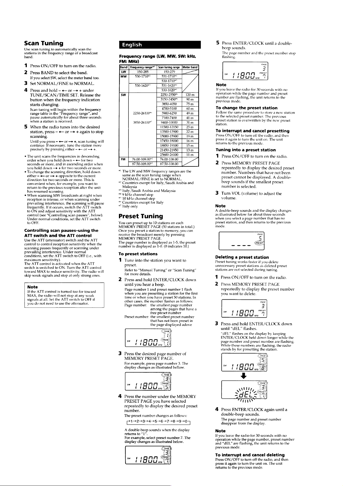
Frequency range
FM: 76.00 - 108.00 MHz
87.50 - 108.00 MHz*
SW: 2250 - 26100 kHz*
3850 - 26100 kHz*
MW: 530 - 1710 kHz
530 - 1620 kHz
LW: 150 - 285 kHz
Speaker
Approx. 66 mm (2 1/8 in.) diameter, 8 Ohms
Maximum output
240 mW (at 10 % harmonic distortion)
Output
i (headphones) jack (ø3.5 mm stereo mini jack)
16 Ohms
Power requirements
DC 4.5 V, three R6 (size AA) batteries
External power source
DC IN 4.5 V
Battery Life (approximate hours)
FM reception 17 46
SW reception 12 33
LW/MW reception 12 33
1
2
3
Sony R6 Sony LR6
(size AA) alkaline
(size AA)
US Model
Canadian Model
AEP Model
E Model
Tourist Model
Dimensions
Approx. 168 × 106 × 35 mm (W × H × D)
(6 5/8 × 4 1/4 × 1 7/16 in.) incl. projecting parts
Mass
Approx. 405 g (14.3 oz) incl. batteries
Supplied Accessories
Carrying case (1)
Short wave guide (1)
Design and specifications are subject to change without
notice.
The AC power adaptor’s operating voltage varies
depending upon the country in which it is sold.
Buy the AC power adaptor in the country you intend
to use it.
Your Sony dealer may not handle all of the above listed
optional accessories. Please ask your dealer for detailed
information on the optional accessories available in your
country.
*1 Italy, Saudi Arabia and Malaysia
*2 Countries except for Italy
*3 Italy only
9-927-687-12
2001E0400-1
© 2001. 5
FM STEREO/SW/MW/LW
PLL SYNTHESIZED RECEIVER
Sony Corporation
Personal Audio Company
Shinagawa Tec Service Manual Production Group
– 1 –

Notes on Chip Component Replacement
• Never reuse a disconnected chip component.
• Notice that the minus side of a tantalum capacitor may be
damaged by heat.
TABLE OF CONTENTS
1. GENERAL
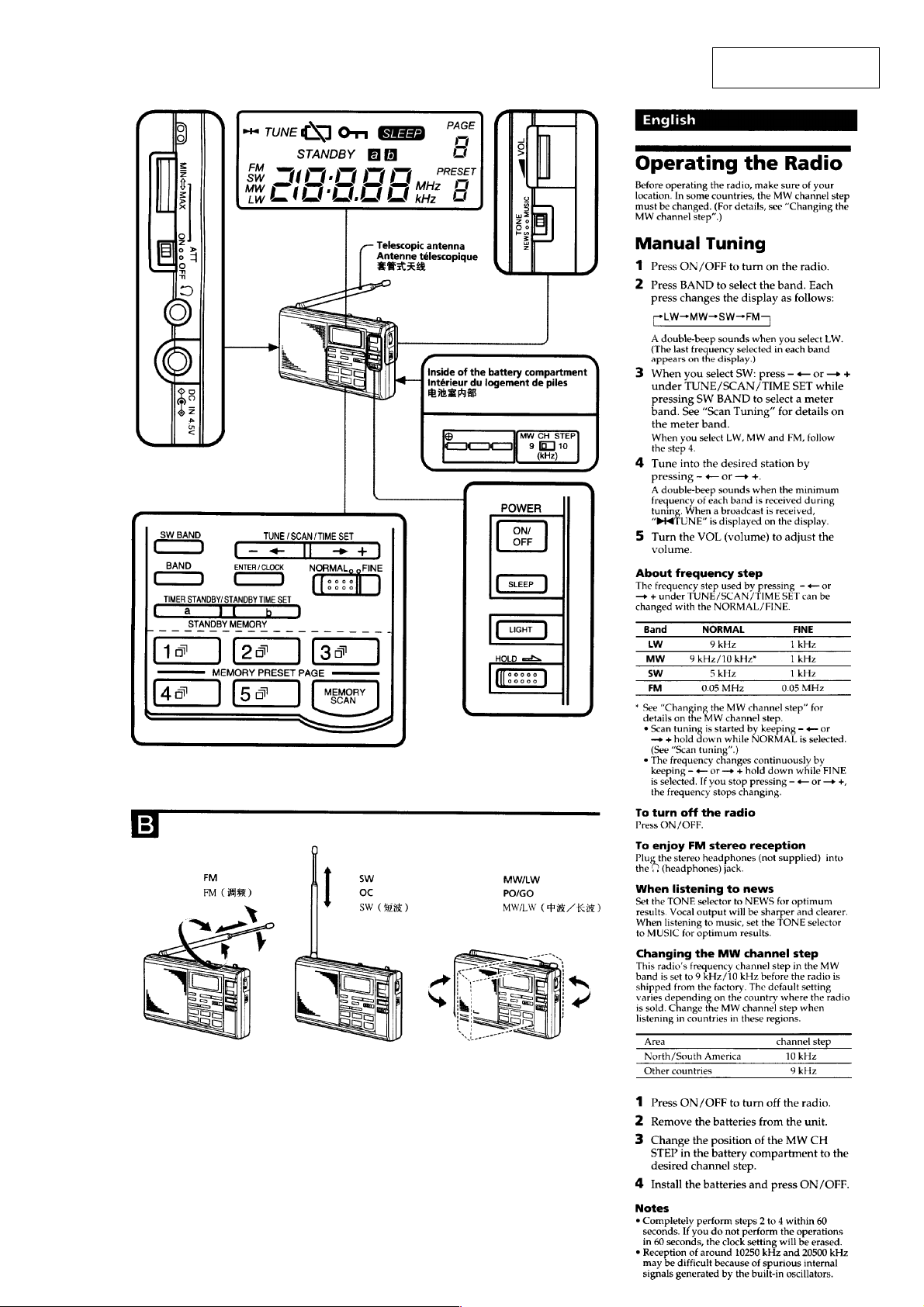
Operating the Radio................................................................. 3
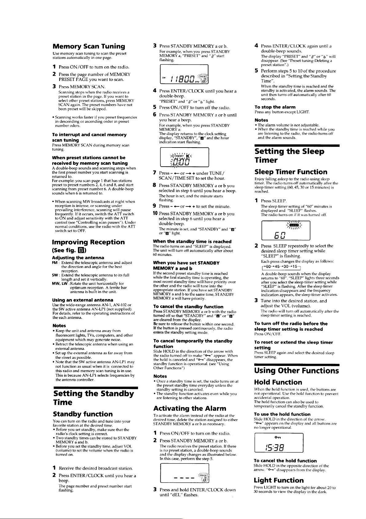
Setting the Standby Time ........................................................ 5
Setting the Sleep Timer ........................................................... 5
Using Other Functions............................................................. 5
2. DISASSEMBLY
2-1. Cabinet (Rear) ..................................................................... 6
2-2. Main Board ......................................................................... 6
2-3. Micon Board ....................................................................... 7
3. ELECTRICAL ADJUSTMENTS
FM Section .............................................................................. 8
SW/MW/LW Section............................................................... 8
FM VCO Adjustment...............................................................9
4. DIAGRAMS
4-1. IC Pin Description............................................................. 10
4-2. Block Diagram .................................................................. 11
4-3. Printed Wiring Board – Main Section – ............................ 13
4-4. Schematic Diagram – Main Section –...............................15
4-5. Printed Wiring Board – Micon Section – .......................... 17
4-6. Schematic Diagram – Micon Section –.............................19
5. EXPLODED VIEW
5-1. Cabinet Section ................................................................. 22
6. ELECTRICAL PARTS LIST.........................................23
– 2 –
SECTION 1
GENERAL
This section is extracted
from instruction manual.
– 3 –
– 4 –
– 5 –
SECTION 2
DISASSEMBLY
Note : Follow the disassembly procedure in the numerical order given.
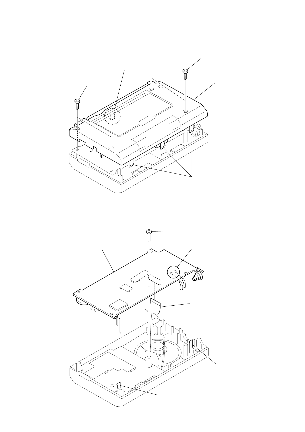
2-1. CABINET (REAR)
4 claw
1 P 3x14
2-2. MAIN BOARD
2 P 3x14
5 cabinet (rear)
3 claws
6 MAIN board
2 P 3x14
1 Removal the solder.
5 CN1
3 claw
– 6 –
4 claw
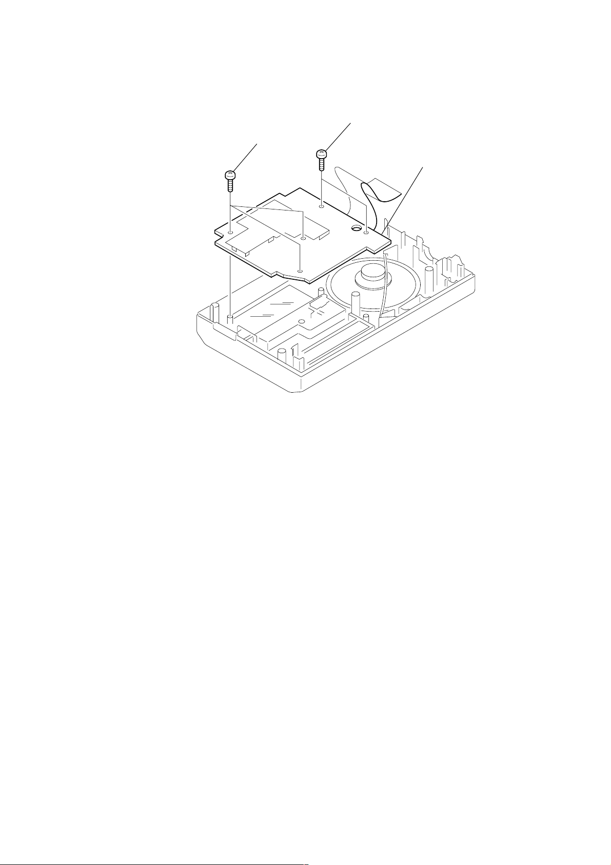
2-3. MICON BOARD
1 BTP 2x8
2 BTP 2x8
3 MICON board
– 7 –
SECTION 3
)
digital
voltmeter
TP
(VT)
ELECTRICAL ADJUSTMENTS
FM SECTION 0 dB = 1 µV
Setting:
BAND switch: FM
VOLUME: MAX
ATT: OFF
TONE: MUSIC
FM RF signal
generator
0.01µF
400Hz, 30% FM modulation
frequency deviation ±22.5kHz
Output level: as low as possible
SW/MW/LW SECTION
Setting:
BAND switch: SW or MW or LW
VOLUME: MAX
ATT: OFF
TONE: MUSIC
(SW)
AM RF signal
generator
10µF
400Hz, 30%
AM modulation
Output level: as low as possible
(MW/LW)
AM RF signal
generator
400Hz, 30%
AM modulation
Output level: as low as possible
telescopic
antenna terminal
set
telescopic
antenna terminal
set
Put the lead-wire
antenna close to
the set.
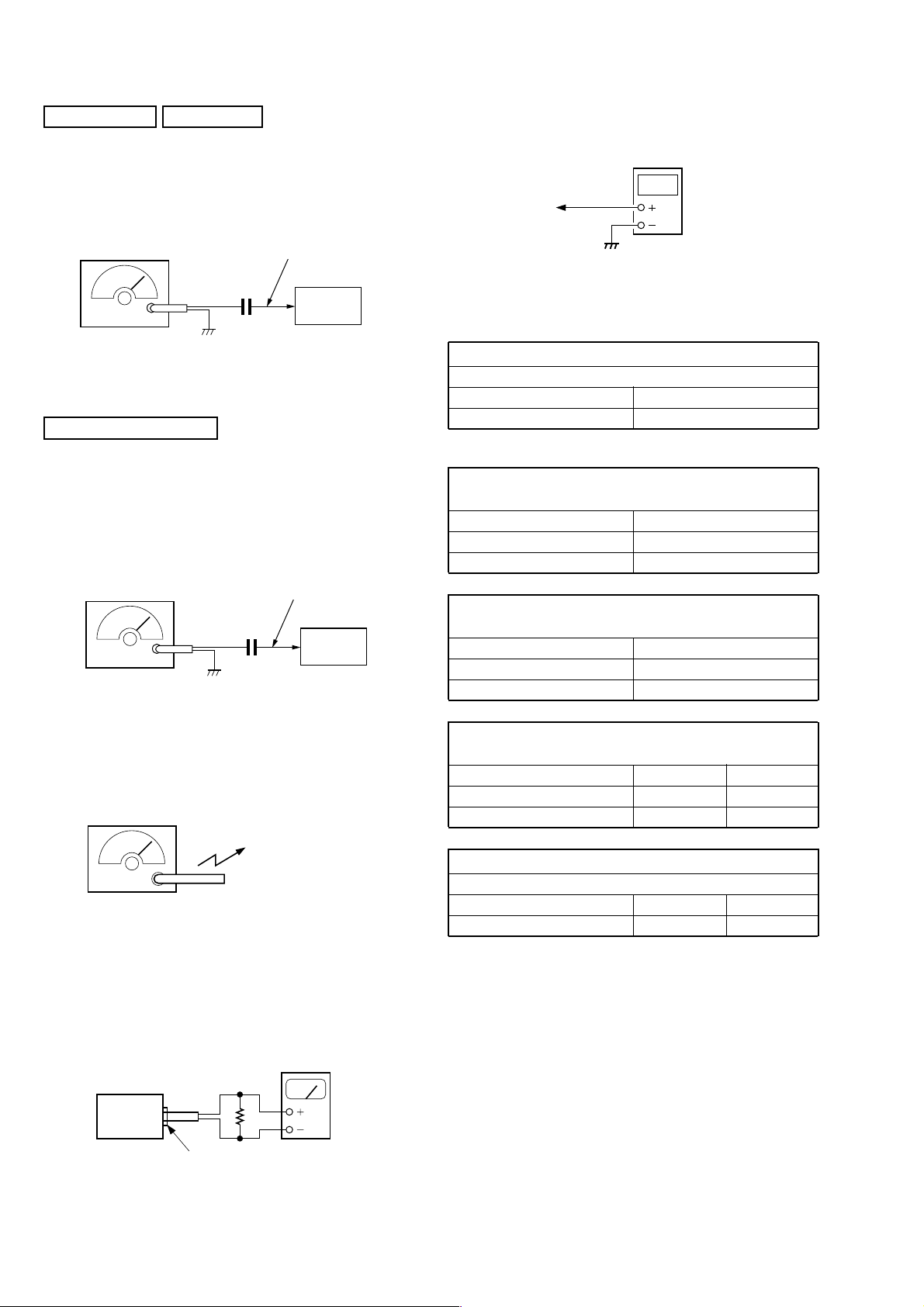
• Connecting Digital Voltmeter (FM, SW, MW and LW)
• Repeat the procedures in each adjustment several times, and the
frequency coverage and tracking adjustments should be finally
done by the trimmer capacitors.
AM IF ADJUSTMENT
Adjust for a maximum reading on level meter.
Frequency Display 11,800 kHz
Adjustment Part T1, T4
LW FREQUENCY COVERAGE
CHECK
Frequency Display 150 kHz
Reading on Digital voltmeter 1.0 - 1.3 V
Adjustment Part <confirmation>
SW FREQUENCY COVERAGE
CHECK
Frequency Display 26,100 kHz
Reading on Digital voltmeter 8.0 - 9.0 V
Adjustment Part <confirmation>
FM FREQUENCY COVERAGE
CHECK
Frequency Display 76 MHz 108 MHz
Reading on Digital voltmeter 2.8 - 4.0 V 9.5 - 11.0 V
Adjustment Part <confirmation> <confirmation>
FM TRACKING ADJUSTMENT
Adjust for a maximum reading on level meter.
Frequency Display 76 MHz 108 MHz
Adjustment Part L11 CT1
Adjustment Location: See page 9.
• Connecting Level Meter (FM, SW, MW and LW)
16 Ω
set
i jack (J1)
level meter
(range: 0.5–5 V ac
– 8 –
 Loading...