

Page 1
ICD-MS1
SERVICE MANUAL
Ver 1.1 2001.03
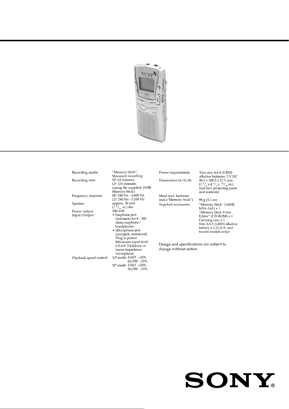
SPECIFICATIONS
US Model
Canadian Model
AEP Model
E Model
Tourist Model
9-927-624-12 Sony Corporation
2001C0500-1 Audio Entertainment Group
C 2001.3 General Engineering Dept.
MEMORY STICK IC RECORDER
Page 2
TABLE OF CONTENTS
1. SERVICING NOTES ............................................... 2
2. GENERAL ................................................................... 3
3. DISASSEMBLY ......................................................... 12
4. TEST MODE.............................................................. 16
5. DIAGRAMS
5-1. Block Diagram – MAIN Section –................................. 19
5-2. Block Diagram
– KEY CONTROL/POWER SUPPLY Section –........... 21
5-3. Printed Wiring Boards – MAIN/SW Board – ................ 23
5-4. Schematic Diagram – MAIN/SW Board – ..................... 27
5-5. Printed Wiring Board – AUDIO Board – ....................... 30
5-6. Schematic Diagram – AUDIO Board – .......................... 33
5-7. IC Pin Function Description ........................................... 39
6. EXPLODED VIEW ................................................... 43
7. ELECTRICAL PARTS LIST ............................... 45
SECTION 1
SERVICING NOTES
Notes on chip component replacement
• Never reuse a disconnected chip component.
• Notice that the minus side of a tantalum capacitor may be dam-
aged by heat.
Flexible Circuit Board Repairing
• Keep the temperature of the soldering iron around 270 ˚C dur-
ing repairing.
• Do not touch the soldering iron on the same conductor of the
circuit board. (within 3 times)
• Be careful not to apply force on the conductor when soldering
or unsoldering.
• Replacement of HD64F7198RVBP16 (IC722) used in this set
requires a special tool. Therefore, it cannot be replaced.
– 2 –
Page 3
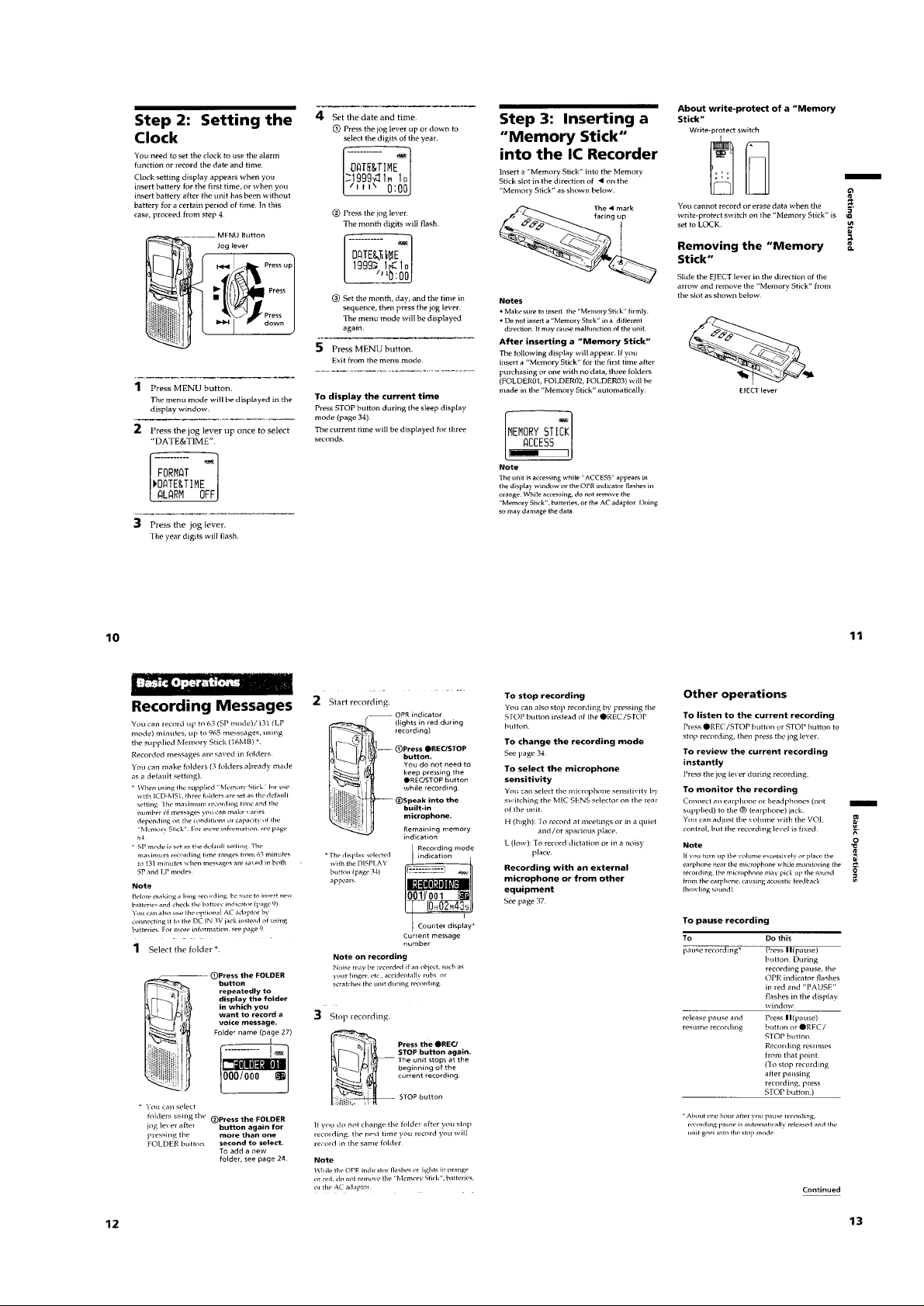
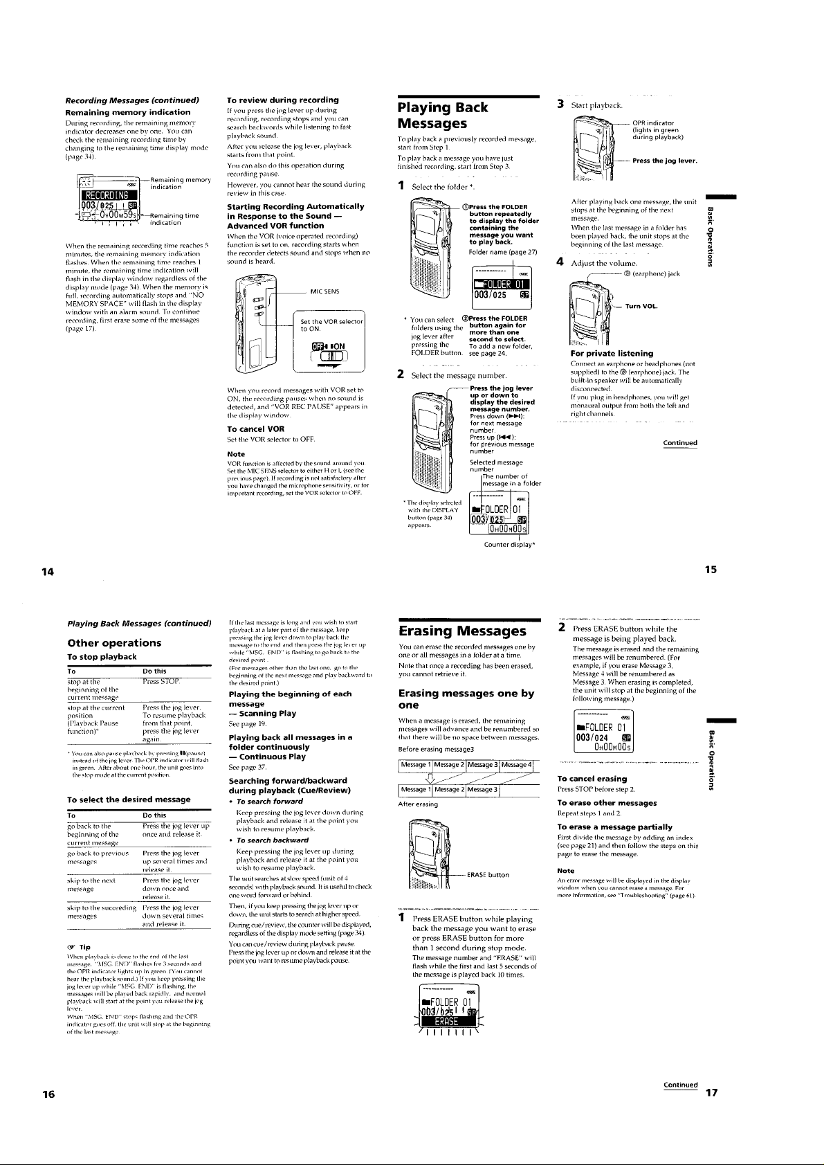
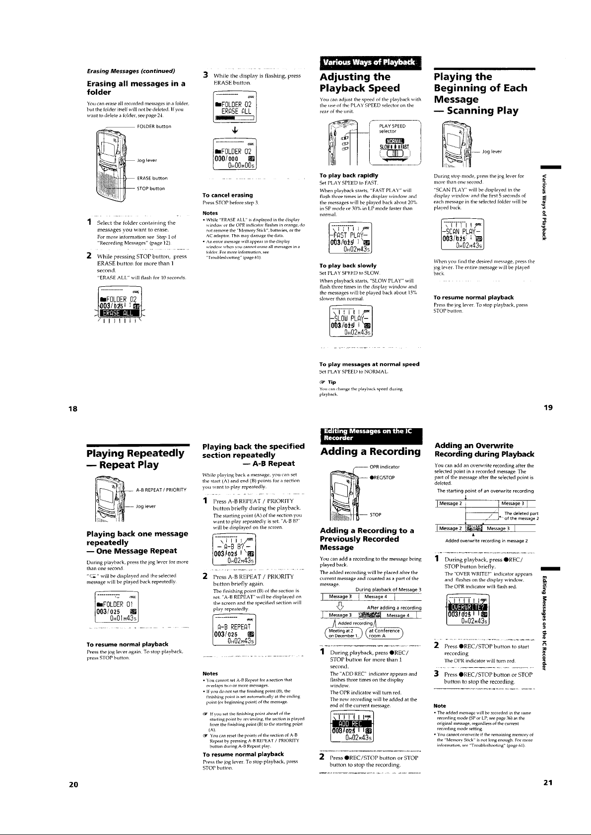
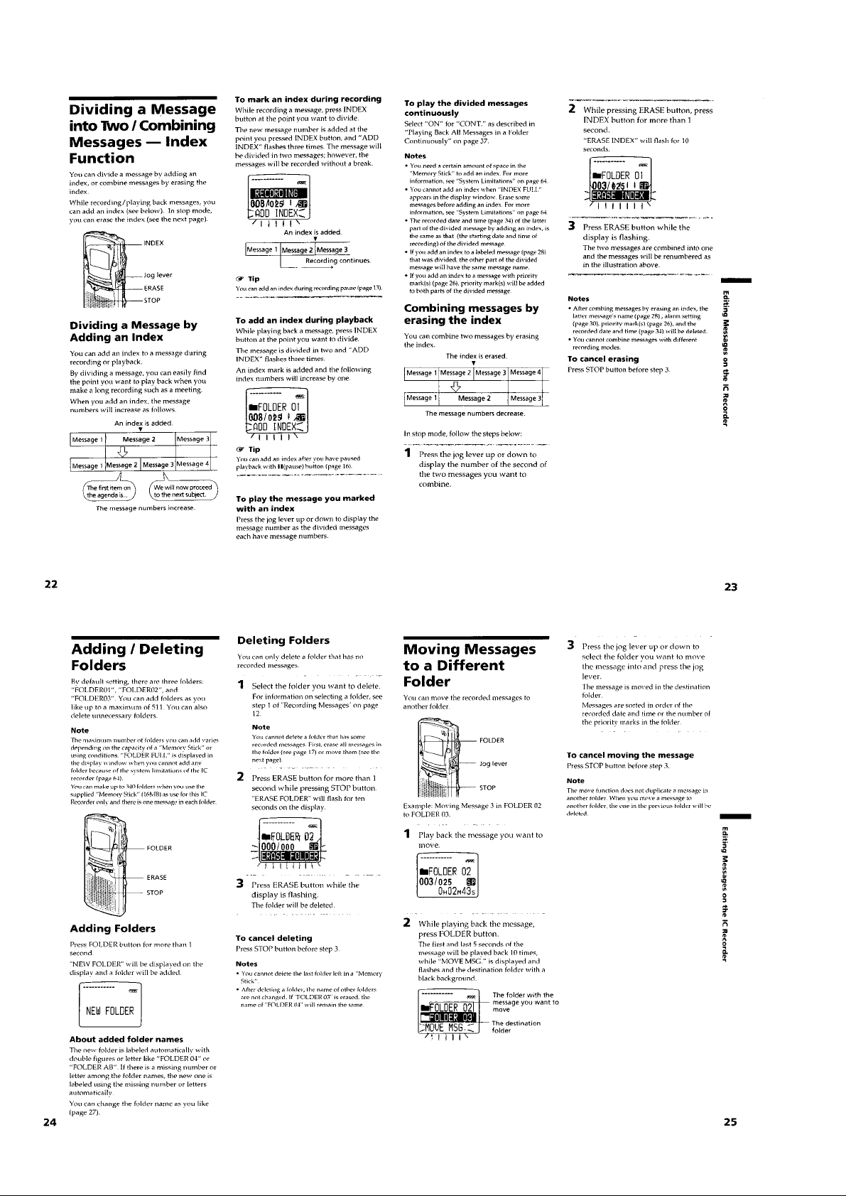
SECTION 2
GENERAL
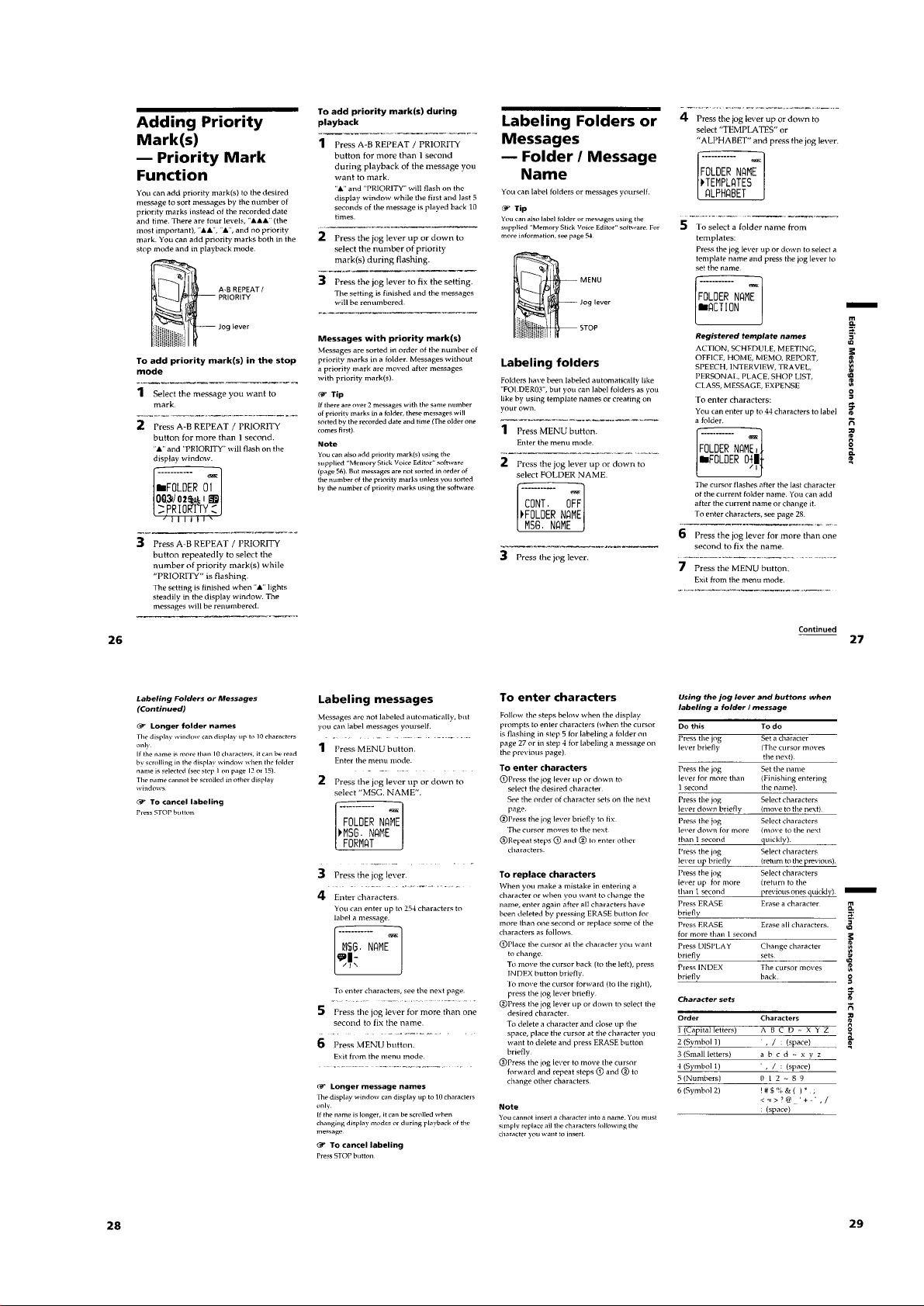
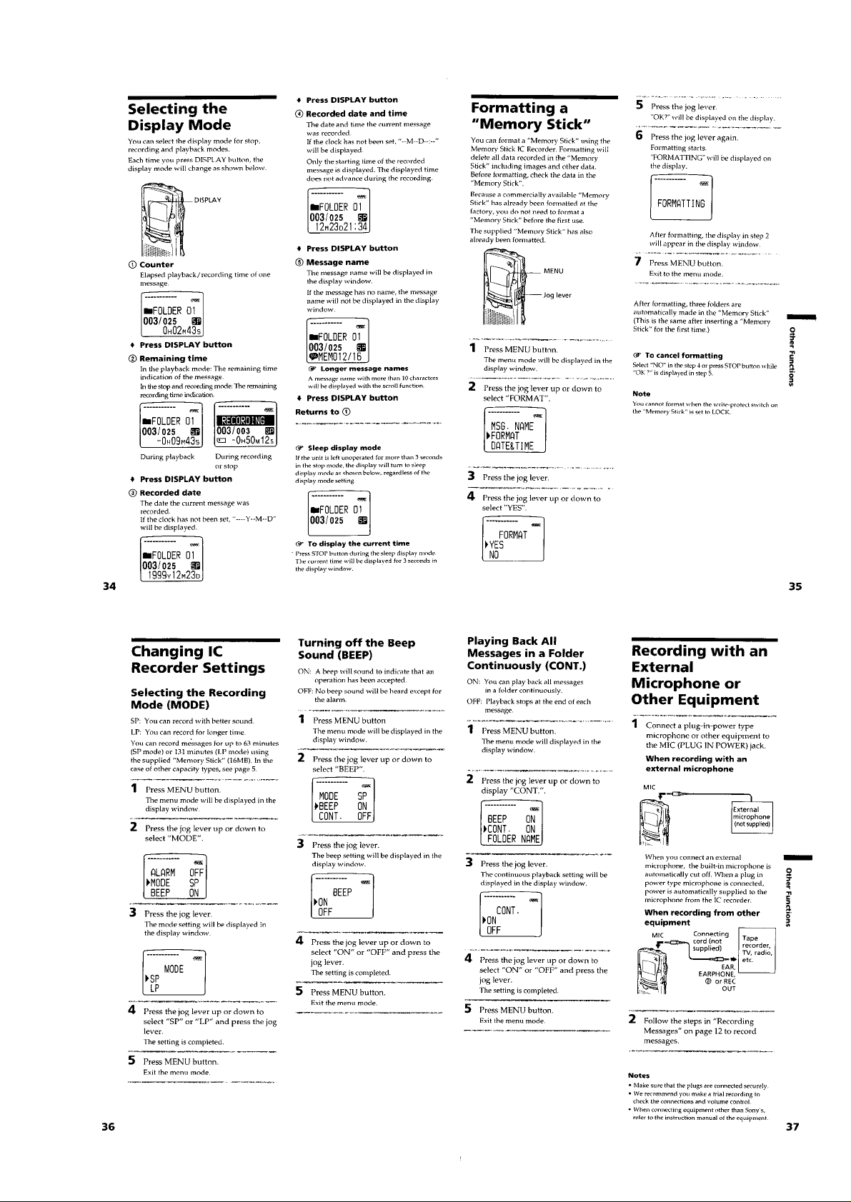
This section is extracted from
instruction manual.
– 3 –
Page 4
– 4 –
Page 5
– 5 –
Page 6
– 6 –
Page 7
– 7 –
Page 8
– 8 –
Page 9
– 9 –
Page 10

– 10 –
Page 11
– 11 –
Page 12

• This set can be disassembled in the order shown below.
SECTION 3
DISASSEMBLY
Set
Note: Follow the disassembly procedure in the numerical order given.
Lid Assy, Upper
Case Assy
Main/SW Board
Eject Mech Assy
Connector Unit, MS
“LID ASSY, UPPER”, CASE ASSY
3 tapping screw
2 Open the battery case lid.
Audio Board,
“Microphone Unit, Back Electret” (MIC161)
1 screw
(B1.7 × 12)
5 Remove two solders of the
speaker lead wires (SP161).
speaker lead wires
4 claw
fabric non woven (RE)
Note: In routing the speaker lead wires,
fix them to the positions shown in figure
using three pieces of fabric non woven (RE).
6 lid assy, upper
4 two
claws
4 two claws
fabric non woven (RE)
7 case assy
– 12 –
Page 13

MAIN/SW BOARD
e
qs LCD assy
8 SW board
7 connector
(CN722)
qd MAIN board
9 Remove two solders of the
LED back light (D720).
qa flexible board
(“indicator module, liquid crystal”)
(CN724)
0 claw
0 two claws
Note: Do not use an excessive force
when raising the MAIN board.
1 Remove two solders of th
battery terminal (+)/(–).
2 tapping screw
5 Raise the MAIN board.
4 connector (CN761)
3 claw
6 flexible board
(“connector unit, MS”) (CN723)
– 13 –
Page 14

EJECT ASSY
Note: When assembling the eject assy,
engage the slider (eject) with
the slot in the knob (eject).
slider (eject)
2 Remove the eject assy
to direction of the arrow.
1 screw
(M1.4 × 1.4)
slot
knob (eject)
“CONNECTOR UNIT, MS”
Note: Open the claw slowly with
a screwdriver,
because it is easily broken.
2 Remove the MS connector unit to
direction of the arrow A.
A
1 Open the claw.
1 Open the claw.
– 14 –
Page 15

AUDIO BOARD, “MICROPHONE UNIT, BACK ELECTRET” (MIC161)
)
Note: On installation AUDIO board, adjust S161, S761,
S763, S764 and knobs (HOLD, DBB)
7 “microphone unit, back electret” (MIC161
1 Raise the
microphone cushion.
2 claw
S764
8 AUDIO board
S161
3 guide (PWB)
S761
knob (HOLD)
three knobs (DBB)
S763
INSTALLATION BACK ELECTRET MICROPHONE UNIT (MIC161)
Note: Follow the assembly procedure in the numerical order given.
guide (PWB)
bosses
6 Remove two solders of the
back electret microphone unit
lead wires (MIC161).
5 claw
4 window (LED)
2 Install the back electret microphone
unit (MIC161), aligning with three bosses.
Note: Take care not to allow the lead wires
to ride on the
!
portion.
#
slot
boss
1 Put two lead wires
in the slot of the guide (PWB).
– 15 –
guide (PWB)
3 Let excess lead wires
through the guide (PWB)
in the arrow direction.
Page 16

SECTION 4
TEST MODE - uCOM Ver:
rabbit b1.00
TEST MODE
[Setting Method of Test Mode]
There are two different methods to set the test mode:
1 Short BP701 (TEST) on the MAIN board with a solder bridge
(connect pin <zmb of IC722 to the ground).
Then, insert the memory stick and turn on the power.
– MAIN BOARD (Side B) –
2 In the normal mode, insert the memory stick. While pressing
[STOP] and [MENU] key, Turn the [HOLD] switch.
the
[Releasing Method of Test Mode]
For test mode set with the method 1:
Turn off the power and remove the memory stick. Then, open the
solder bridge on BP701 (TEST) on the MAIN board.
For test mode set with the method 2:
Turn off the power and remove the memory stick.
[Operation in the Test Mode]
When the test mode is set, the LCD displays as shown below.
LCD display
1. Audio test
• Pressing the z key causes “SP DSP LOOP” to be displayed
on the LCD and the LED lights in red.
• Pressing the jog lever causes “LP DSP LOOP” to be displayed
on the LCD and the LED lights in green.
• Moving down the jog le ver causes “MUTE ON” to be displayed
on the LCD and the LED lights in amber.
• Moving up the jog lever causes “MUTE OFF” to be displayed
on the LCD.
• Pressing the [MENU] key causes “1.3 kHz BEEP” to be dis-
played on the LCD and a beep to sound.
• Pressing the [STOP] key causes the set to return to the state at a
setting of test mode.
JC724
4
5
IC523
1
+
C526
3
BP701 Short: Test mode
1
4
BP701
(TEST)
(
Open: Normal mode
IC723
C730
R756R711R710
1-675-564-
)
2. VOR test
• Turning the [VOR] switch ON causes “VOR TEST” to be dis-
played on the LCD, and when sounds are detected, “SOUND
!!!” is displayed on the LCD and the LED lights in red. Also,
when no sound is detected, “NO SOUND” is displayed on the
LCD and the LED goes off.
• Turning the [VOR] switch OFF causes the set to return to the
state at a setting of test mode.
3. Sleep test
• Pressing the S key causes the set to enter sleep state in one
second.
8
(When the [HOLD] switch is OFF , the LCD goes off. Also, when
ON, “SLEEPING” is displayed on the LCD.)
5
• Pressing another key causes the set to release sleep state.
4. Power supply test (stop mode)
• When power supply is a dry battery and its voltage is over 2V,
the LCD lights in green. Also when the v oltage is belo w 2V the
LED lights in red.
• When power supply is a DC power supply, the LED lights in
amber.
5. Destination switching
Pressing simultaneously the [ A-B REPEAT] key and jog lever
z
causes “for JAPAN” to be displayed on the LCD and LED lights
in green. Also, pressing simultaneously the [ A-B REPEAT] and
z
the z keys causes “for WORLD” to be displayed on the LCD
and LED lights in red.
– 16 –
Page 17

6. LCD test
• While pressing the [DISPLAY] key, move down the jog lever
causes “CONTRAST v” to be displayed on the LCD and the
contrast of LCD increases. Also, while pressing the [DISPLAY]
key, move up the jog lever causes “CONTRAST V” to be displayed on the LCD and the contrast of LCD decreases.
• LCD lights on all while the [FOLDER] key is pressed together
with the [DISPLAY] key, and “LCD TEST” is displayed on the
LCD if releasing keys. Also, LCD lights off all while the
[INDEX] key is pressed together with the [DISPLAY] key, and
“LCD TEST” is displayed on the LCD if releasing keys.
7. Menu reset
Pressing simultaneously the [STOP] and [ERASE] keys causes
the set to return to initial conditions except the destination and
contrast setting.
– 17 –
Page 18

SECTION 5
DIAGRAMS
ICD-MS1
5-1. BLOCK DIAGRAM – MAIN Section –
AIN1
3
MIC161
MIC
J161
MIC
(PLUG IN POWER)
I/01 – I/016 A0 – A16
29 – 36, 38 – 45
A/D
CONVERTER
MIC AMP
IC161
1 –8, 18 – 25, 48
S-RAM
IC727
TXON/
OFF
B. P. F./
L. P. F.
S161
MIC SENS
HIGH
LOW
AGC
IC162
XUB
ATTENUATOR
XLB
XCE1
XOE
COMPRESSOR
R/W
1128261514
ADPCM
IC164 (1/2)
PCM
GSX
1
VOR
DETECTOR
IC163
REAL
TIME
CLOCK
IC721
EEPROM
IC723
PCMSO
27
/AIRQ
/TIRQ
RESET
DATA
CLK
CE0
CE1
RDY
5-2. BLOCK DIAGRAM – KEY CONTROL/POWER SUPPLY Section –
RTCINT
SYSTEM CONTROLLER
IC722 (1/2)
PCMSI
26
DIN
17
7
6
4
5
3
8
DI
3
DO
4
SK
2
CS
1
7
6
ADPCM
EXCK
18
PDN
DEN
IS
25
15
19
21
72
71
69
68
70
149
17
1
153
87
DSPRX
XDPDN
XDDEN
TXD2
RXD2
SCK2
RTCINT1
RTCCE
XEPCS
XEPBUSY
EPRST
DSPTX
XBCK
SYNC
LMUTE
BEEPCTL
BTLSE
20
77
159
84
88
74
IC169
IR
24
ADPCM
BCLK
29
PULLUP B+
PCMRO
28
SYC
23
MCK
20
DIVIDER
IC105
LINE
MUTING
Q161
B+ SWITCH
Q167
22
PCMRI
BEEP TONE
BTL CONTROL
Q163 (1/2)
ADPCM
IC164 (2/2)
EXPANDER
+
BUFFER
Q162
SWITCH
PCM
RXON/
OFF
POWER AMP
IC168
ATTENUATOR
L. P. F.
CONVERTER
EARPHONE
MUTING
Q165
D/A
YFRO
11
(SPEAKER)
(EARPHONE)
SP161
J162
RV161
VOL
v
A
(Page 21)
Ref No.
A
(Page 20)
S1
S2
S3
S4
S5
S6
S721
S722
S723
S725
RTCINT
PANEL DESIGNATION
STOP
DISPLAY
MENU
INDEX
ERASE
FOLDER
S
REC/STOP
z
z
A-B REPEAT/ PRIORITY
(JOG)
3.3V B+
3.3V B+
SWITCHING
Q721
SWITCHING
Q723, 725
KEY
MATRIX
S1 – 6,
S721 – 723, S725
S7
MEMORY STICK
IN DETECT
S761
.
HOLD
OFF
HOLD
35 – 37 167 – 170
120
32
31
151
166
KEYIN0 – KEYIN3KEYCTL0 – KEYCTL2
WAKEUP
WAKEMSK
WAKEMSK2
MSEJ
XHOLD
SYSTEM CONTROLLER
IC722 (2/2)
PULLUP
XRST
MSPOW
154
121
42
PULLUP B+
LCD VC
3.3V
REGULATOR
RESET SIGNAL
GENERATOR
SYSTEM CONTROLLER (IC722),
S-RAM (IC727), REAL TIME CLOCK (IC721),
EEPROM (IC723), LCD, LED B+
+3V
IC728
IC726
3.3V
(MEMORY STICK B+)
3.5V
(DIVIDER (IC165) B+)
3.3V
(ADPCM (IC164) B+)
3.3V B+
+3.3V
REGULATOR
IC524
+3.3V
REGULATOR
IC523
+3.5V
REGULATOR
IC564
+3.3V
REGULATOR
IC562
VOUT
1
CHIP ENABLE
VREF &
CE
3
EEROR
AMP
D521
PWM
COMPARATOR
OSC
OUTPUT
CIRCUIT
POWER
CONTROL
IC522
EXT
BATT B+
POWER AMP
(IC168) B+
SWITCHING
REGULATOR
Q522
5
L521
89 – 92, 94, 96 – 102, 105 – 108
D0 – D15 A1 – A17
MSDIO13MSCLK11MSBS9MSINS24LCDD025LCDDI78LCDSCK
12
BS
DIO
SCLK
MEMORY STICK LCD720
05
INS
44 – 50, 52, 54 – 59, 62 – 64
SDA
LIQUID CRYSTAL DISPLAY MODULE
XLCDCS
2 76 113
CS
SCL
XLCDRST
RST
XUB
EXTAL
X721
3.7706MHz
XLB
115
XTAL
1051514
XRD
SRCS
TEST2
175
BP701
(TEST)
SHORT : TEST MODE
OPEN : NORMAL MODE
30
RDWR
147
XVORIN
D720
(LCD BACK LIGHT)
D761
OPR
– 1 (PALY : GRN)
– 2 (REC : RED)
SPOWER
MICPOW
BATT
XDCIN
41
MIC AMP (IC161), AGC (IC162),
38
173
150
BATT B+
3.3V
VOR DETECTOR (IC163) B+
+3.3V
REGULATOR
IC563
DC/DC CONVERTER
IC561
DC/DC CONVERTER
CONTROL
Q521
VOLTAGE DETECT
IC521
VOLTAGE DETECT
IC1, Q1
LINE FILTER
T1
DRY BATTERY
SIZE “AAA”
(IEC DESIGNATION R03)
2PCS. 3V
J1
DC IN 3V
+
–
VORSW
AMP ON
AMPOW
40
HPMUTE
85
HPJACK
144
LED DRIVE
Q724
– 1
LED DRIVE
Q761 (1/2)
– 2
LED DRIVE
Q761 (2/2)
160
146
145
LIGHT
GRNLED
REDLED
SWITCH
Q163 (2/2)
• SIGNAL PATH
: PLAY
: REC
S764
VOR
ON
OFF
S763
PLAY SPEED
FAST
NORMAL
SLOW
05
171
SPEED
172
– 19 –
– 20 –
– 21 –
– 22 –
Page 19

ICD-MS1
e
5-3. PRINTED WIRING BOARDS – MAIN/SW Board –
1
MAIN BOARD
A
B
C
D
2 3 4 5 6 7 8 9 10 11 12 13 14 15 16 17 18 19 20 21 22 23 24 25 26 27 28 29 30
S722
REC/STOP
S721
(SIDE A)
C746
C744
2
C761
IC726
Note on Printed Wiring Boards:
• X : parts extracted from the component side.
• Y : parts extracted from the conductor side.
f
•
: internal component.
• b : Pattern from the side which enables seeing.
MAIN BOARD
(SIDE B)
LCD720
LIQUID CRYSTAL
DISPLAY MODULE
(The other layers' patterns are not indicated.)
C747C749C753
X721
C760
C759
1
C702
3
C701
R708
JC721
89 87 84 81 78 75 71 67 63 59 56 53 50 47 45
91 88 86 82 79 76 72 68 64 60 55 51 48 44 43
94 92 90 83 77 74 70 66 62 58 54 49 46 42 40
97 95 93 85 80 73 69 65 61 57 52 41 39 38 37
100 99 98 96
103 104 102 101 29 30 32 31
107 108 106 105
111 112 110 109
115 116 114 113 17 18 20 19
119 120 118 117 13 14 16 15
122 123 121 124 8 10 11 12
125 126 127 129 140 145 149 153 157 161 168 173 5
128 130 134 137 142 146 150 154 158 162 165 171 2 4 6
131 132 136 139 143 148 152 156 160 164 167 170 174 176
133 135 138 141 144 147 151 155 159 163 166 169 172 175
C755
R704
R768
C758
* IC722
R703
R767
36 33 35 34
25 26 28 27
21 22 24 23
R702
R769
7 9
C750
R726
R764
R737
R750
FB702
R740
R741
FB701
R742
3
1
C731
R765
R730
R766
R727
R712
R723
R713
R751
R758
R757
AK
A
D721
IC721
R725 R724
CN724
122
C742
–1–3–2
C727
C737
C741
AAA
C763
C740
D722
KKK
C739
3
IC728
Q723
BCE
–1–3–2
R760
C724C726
C756
R728
C733
Q725
R732
R733
R729
C734
SDG
Q721
SDG
C735
C736
C738
D723
AAA
KKK
C728
24
R701
2
R759
1
R763
RB721RB722
1
1
R738
10
C722
R752
R721
JC723
R753
B
C
Q724
E
20
S723
A-B REPEAT/
PRIORITY
11
D720
(LCD BACK LIGHT)
K
A
D3
S4
INDEX
S6
FOLDER
Caution:
Pattern face side: Parts on the pattern face side seen from
(Side B) the pattern face are indicated.
Parts face side: Parts on the parts face side seen from
(Side A) the parts face are indicated.
• Main board is six-layer printed board.
Howev er , the patterns of intermediate-layer ha v e not been included in this diagrams.
IC722 is not replaceable
*
• Lead Layouts
surfac
Lead layout of conv entional IC CSP (chip size package)
• Semiconductor
Location
Ref. No. Location
D1 J-24
D2 H-25
D3 B-23
D521 H-6
D721 C-12
D722 D-10
D723 D-9
IC1 I-15
IC521 I-11
IC522 H-9
IC523 K-11
IC524 K-10
IC721 D-12
IC722 C-5
IC723 K-13
IC726 D-3
IC727 F-10
IC728 C-11
Q1 I-15
Q521 J-11
Q522 G-7
Q721 D-8
Q723 D-10
Q724 B-12
Q725 C-8
E
+
R706
R739
R734
R747
C704
R707
C721
+
C525
C752
+
+
R746
R744
R745
CN723
110
R735
1-675-564-
11
(11)
L521
G
S
Q522
K
D521
C524
MEMORY
STICK
D
A
C523
25
+
5
4
IC522
1
3
C527
IC727
S725
(JOG)
48
C703
R709
2
1
+
R527
Q521
R522
5
1
R528 R736
IC521
C522
R523
1C 2B 2E
1E 1B 2C
R521
C757
4
IC524
3
1
3
R525
R526
10
C521
JC724
4
5
IC523
1
3
C526
CN722
+
BP701
(TEST)
20
11
C730
R756R711R710
1-675-564-
8
5
11
(11)
1
IC723
4
SW BOARD
3
(SIDE A)
120
Q1
SDG
2
IC1
1
CN1
11
C9
10
R2
R1
S7
MEMORY STICK
IN DETECT
R6
11
1-675-563-
(11)
21
20
F
A
AUDIO BOARD
CN761
CN725
G
40
R705
C762
1
H
JC722
I
J
K
05
DRY BATTERY
SIZE “AAA”
(IEC DESIGNATION R03)
2PCS.3V
J1
DC IN 3V
+
–
C4
+
C5
STOP
(SIDE B)
+
C7
S1
C1
BP1
S3
MENU
S5
ERASE
11
1-675-563-
(11)
T1
C2
C3
R8
A
K
D1
S2
DISPLAY
A
K
D2
SW BOARD
– 23 –
– 24 –
– 25 –
– 26 –
Page 20

5-4. SCHEMATIC DIAGRAM – MAIN/SW Board – • See page 36 for Waveforms. • See page 37 for IC Block Diagrams.
ICD-MS1
Note on Schematic Diagram:
• All capacitors are in µF unless otherwise noted. pF: µµF
50 WV or less are not indicated except for electrolytics
and tantalums.
• All resistors are in Ω and 1/
specified.
• % : indicates tolerance.
f
•
• C : panel designation.
• U : B+ Line.
• Power voltage is dc 3 V and fed with regulated dc power
• Voltages and waveforms are dc with respect to ground
• Voltages are taken with a VOM (Input impedance 10 MΩ).
• Waveforms are taken with a oscilloscope.
• Circled numbers refer to waveforms.
• Signal path.
*
• The voltage and waveform of CSP (chip size package) can-
: internal component.
supply from external power voltage jack.
under no-signal conditions.
no mark : PLAY
( ) : REC
Voltage variations may be noted due to normal production tolerances.
Voltage variations may be noted due to normal production tolerances.
F : PLAY
L : REC
: Impossible to measure
∗
IC722 is not replaceable
not be measured, because its lead layout is different form
that of conventional IC.
4
W or less unless otherwise
– 27 –
– 28 –
– 29 –
Page 21

ICD-MS1
5-5. PRINTED WIRING BOARD – AUDIO Board –
• Semiconductor
Location
Ref. No. Location
D561 I-3
D562 D-11
D761 B-12
IC161 F-11
IC162 E-9
IC163 G-3
IC164 F-8
IC165 G-8
IC168 D-5
IC169 G-5
IC561 J-3
IC562 J-5
IC563 J-4
IC564 I-8
Q161 C-5
Q162 G-7
Q163 E-6
Q165 B-5
Q167 G-8
Q761 C-12
Note on Printed Wiring Board:
• Y : parts extracted from the conductor side.
• b : Pattern from the side which enables seeing.
(The other layers' patterns are not indicated.)
Caution:
Pattern face side: Parts on the pattern face side seen from
(Side B) the pattern face are indicated.
Parts face side: Parts on the parts face side seen from
(Side A) the parts face are indicated.
• AUDIO board is a six-layer printed board.
However, the patterns of intermediate-layer have not
been included in this diagram.
1
A
AUDIO BOARD
B
C
D
E
F
G
H
R771
R774
I
J
K
05
2 3 4 5 6 7 8 9 10 11 12 13
(PLUG IN POWER)
FB162
C175
3
IC162
2
R172
C174
R173
R174
C182
J161
C173
MIC
Q761
K
A
R179
D562
R772
D761
–2–1
2C
1C
2BE1B
RED
BLK
21
40
+
C170
D761
OPR
–1 (PLAY : GRN)
–2 (REC : RED)
C161
C172
R777
R776
C169
C168
R168
R169
C167
FB161
C166
R170
C162
C171
R161
+
R162
D563
20
1
R175
5
1
R164
C163
K
A
C176
3
4
R773
R189
R166
R167
1
IC161
5
+
CN761
11
1-675-565-
(11)
(SIDE A)
R778
R561
R562
S761
HOLD
HOLD
OFF
J162
v
(EARPHONE)
AUDIO BOARD
R185
S
Q165
D
G
C196
B
FASTSLOW
IC168
C
E
4
1
5
IC562
1
+
C563
C133
8
S763
PLAY SPEED
NORMAL
MIC SENS
HIGH LOW
S764
VOR
OFF ON
IC563
+
Q161
5
S161
51
4
–2
5
4
IC561
R775
–1
C561
R195
+
C565
3
3
1
C562
RV161
VOL
+
C566
+
C567
8
IC163
1
L561
AK
D561
4
2
5
R133
C131
4
3
R196
C132
R197
R131
Q163
2B E 1B
2C 1C
5
IC169
1
+
C564
R136
C188
R130
C187
4
R137
FB133FB132
C134
+
R135
R184
R134
R132
C186
C130
C199
R199
R198
3
R183
15
16 30
Q162
SP161
(SPEAKER)
(SIDE B)
FB131
C177
R177
R178
R181
R180
ECB
R186
C180
IC164
4
IC165
5
ECB
Q167
C189
5
IC564
1
BLK
RED
C179
1
3
1
C183
4
3
+
C181
11
1-675-565-
(11)
MIC161
MIC
A
MAIN BOARD
CN725
– 30 –
– 31 –
– 32 –
Page 22

5-6. SCHEMATIC DIAGRAM – AUDIO Board – • See page 36 for Waveforms. • See page 37 for IC Block Diagrams.
ICD-MS1
Note on Schematic Diagram:
• All capacitors are in µF unless otherwise noted. pF: µµF
50 WV or less are not indicated except for electrolytics
and tantalums.
• All resistors are in Ω and 1/
specified.
• C : panel designation.
• U : B+ Line.
• Power voltage is dc 3 V and fed with regulated dc power
supply from external power voltage jack.
no mark : PLAY
( ) : REC
• Voltages are taken with a V OM (Input impedance 10 MΩ).
Voltage v ariations may be noted due to normal production
tolerances.
• Waveforms are taken with a oscilloscope.
Voltage v ariations may be noted due to normal production
tolerances.
• Circled numbers refer to waveforms.
• Signal path.
F : PLAY
L : REC
– 33 – – 34 – – 35 –
4
W or less unless otherwise
Page 23

• Waveforms
– MAIN Board –
1 IC522 5 (EXT), Q522 (Gate)
2V/DIV, 2µs/DIV
3.7 Vp-p
9.8 µs
2 IC721 6 (CLK), IC722 qj (RTCCE)
2V/DIV, 500ns/DIV
4.3 Vp-p
1.3 µs
3 IC722 uj (XBCK)
2V/DIV, 500ns/DIV
4.8 Vp-p
535 ns
4 IC722 <zzb (XTAL)
1V/DIV, 100ns/DIV
3.3 Vp-p
264 ns
5 IC722 <zb. (SYNC)
2V/DIV, 50µs/DIV
3.9 Vp-p
6 Q522 (Drain)
2V/DIV, 5µs/DIV
9.8 µs
– AUDIO Board –
7 IC164 w; (MCK), IC165 4 (OUT)
2V/DIV, 50ns/DIV
71 ns
8 IC164 wk (SYC), IC165 3 (IN)
2V/DIV, 50µs/DIV
91 µs
9 IC169 2 (IN)
2V/DIV, 500ns/DIV
4.2 Vp-p
4.6 Vp-p
3.1 Vp-p
4.8 Vp-p
0 IC561 4 (LX)
2V/DIV, 2µs/DIV
6.3 µs
qa Q162 (Emitter), Q167 (Collector)
2V/DIV, 50µs/DIV
91 µs
qs Q167 (Base)
2V/DIV, 50µs/DIV
91 µs
5.6 Vp-p
3.4 Vp-p
3.9 Vp-p
• IC Block Diagrams
– MAIN Board –
IC522 XC6368A351MR
VOUT
1
VDD
2
CE
3
SOFT START,
VREF WITH
CE
+
–
ERROR
AMP
IC721 RTC4574JE-TP
VDD
1
FOUT
2
CEO
3
/AIRQ
/TIRQ
CLK
DATA
CE1
FCON
GND
4
5
6
7
8
9
32.768kHz
10
OSC
INTERRUPTS
CONTROLLER
BUS
INTERFACE
CIRCUIT
OUTPUT
CONTROLLER
DIVIDER
– AUDIO Board –
IC163 NJM2072M
INPUT
1
GAIN CONT
2
3
AMP OUT
GND
4 5
PHASE
COMPENSATION
PWM/PFM
CONTROLLER
PWM
COMPARATOR
+
–
RAMP WAVE
GENERATOR,
ALARM
REGISTER
SHIFT
REGISTER
CONTROL
REGISTER
TIMER
REGISTER
CLOCK&
CALENDER
8
7
6
OSC
VCC
OUTPUT2
OUTPUT1
RECOVERY
TIME CAP
BUFFER,
DRIVER
20
19
18
17
16
15
14
13
12
11
IC523, 524 XC62HR3102MR
NC
1
VIN
2 5
CURRENT
LIMIT
REFERENCE
VOLTAGE
+
–
EXT
5
GND
4
NC
NC
NC
NC
NC
NC
NC
NC
NC
NC
CE
OUTPUT
3
CONTROL
VOUT
VSS
4
IC164 ML7029MBZ020
GSX
1
NC
2
20kΩ
AIN–
VFRO
DG
PDN
–
3
+
NC
4
SG
5
NC
6
VA
7
NC
8
AG
9
NC
10
11
20kΩ
NC
12
NC
13
14
15
A/D
CONVERTER
REFERENCE
VOLTAGE
IC165 XC25A08510MR
CE
5
21 3
CLKINVSS VDD
CLKOUT
4
BUFFER
1/2
VCO
L.P.F.
PHASE
DETECTOR
COUNTER
D/A
CONVERTER
1/N
TXON/OFF
B. P. F./L. P. F. ATTENUATOR
ATTENUATOR
L. P. F. ATTENUATOR RXON/OFF
+
IC561 XC6371C402PR
SLOW
START
REFERENCE
VOLTAGE
PHASE
COMPARATOR
+
–
CHIP
ENABLE
VOUT
NC
1
VDD
2
CE
3
PCM
COMPRESSOR
ADPCM
PCM
EXPANDER
MCU
INTERFACE
30
VD
29
BCLK
28
SYNC
27
PCMSO
26
PCMSI
25
IS
24
IR
23
PCMRO
22
PCMRI
21
NC
20
MCK
19
DEN
18
EXCK
17
DIN
16
DOUT
VLX
LIMITER
PWM CONTROL
OSC 50/100/180kHz
BUFFER
VSS
5
LX
4
IC562 XC62HR3302MR
IC563 XC62HR3102MR
IC564 XC62HR3502MR
NC
1
VIN
2 5
CURRENT
LIMIT
+
–
VOUT
91 µs
535 ns
– 36 –
– 37 –
CE
OUTPUT
3
CONTROL
REFERENCE
VOLTAGE
VSS
4
– 38 –
Page 24

5-7. IC PIN FUNCTION DESCRIPTION
• MAIN BOARD IC722 HD64F7198RVBP16 (SYSTEM CONTROLLER)
Pin No.
1 XEPCS O Chip select signal output to the EEPROM (IC723) “L” active
2 XLCDCS O Chip select signal output to the liquid crystal display module (LCD720) “L” active
3 VCC — Power supply terminal (+3.3V)
4 PA23 O Not used (open)
5 SRCS O Chip enable signal output to the static RAM (IC727) “L” active
6 PA21 O Not used (open)
7 PA20 O Not used (open)
8 VSS — Ground terminal
9 MSINS I
10 XRD O Output enable signal output to the static RAM (IC727) “L” active
11 MSBS O Serial bus state signal output to the memory stick
12 MSDIO I/O Serial data input/output with the memory stick
13 MSCLK O Serial clock signal output to the memory stick
14 XUB O Data bite control signal output to the static RAM (IC727) “L” active
15 XLB O Data bite control signal output to the static RAM (IC727) “L” active
16 XWAIT I Not used (open)
17 RTCCE O Chip enable signal output to the real time clock (IC721) “H” active
18 PA4 O Not used (open)
19 PA0 O Not used (open)
20 DSPTX O Playback serial data output to the ADPCM (IC164)
21 DSPRX I Recording serial data input from the ADPCM (IC164)
22 VCC — Power supply terminal (+3.3V)
23 VSS — Ground terminal
24 LCDDO O Serial data output to the liquid crystal display module (LCD720)
25 LCDDI I Serial data input from the liquid crystal display module (LCD720)
26 VSS — Ground terminal
27 VCC — Power supply terminal (+3.3V)
28 PB17 O Not used (open)
29 PB16 O Not used (open)
30 RDWR O Read/write data output to the static RAM (IC727) “L”: write data , “H”: read data
31 WAKEMSK2 O X (R) sync control signal output terminal
32 WAKEMSK O X (R) sync control signal output terminal
33 VSS — Ground terminal
34 KEYCTL3 O Key send signal output to the key matrix Not used (open)
35 to 37
38 MICPOW O
39 VCC — Power supply terminal (+3.3V)
40 AMPOW O Power supply on/off control signal output to the power amplifier (IC168) “H”: power on
41 SPOWER O Power supply on/off control signal output to the ADPCM (IC164) “H”: power on
42 MSPOW O Power supply on/off control signal output to the memory stick “H”: power on
43 VSS — Ground terminal
44 to 50 A17 to A11 O Address signal output to the static RAM (IC727)
51 VSS — Ground terminal
Pin Name
KEYCTL2 to
KEYCTL0
I/O Description
Memory stick insert detection signal input terminal
“L”: memory stick in, “H”: memory stick out
O Key send signal output to the key matrix
Power supply on/off control signal output to the mic amplifier (IC161)
“H”: power on (rec mode)
– 39 –
Page 25

Pin No.
52 A10 O Address signal output to the static RAM (IC727)
53 VCC — Power supply terminal (+3.3V)
54 to 59 A9 to A4 O Address signal output to the static RAM (IC727)
60 VCC — Power supply terminal (+3.3V)
61 VSS — Ground terminal
62 to 64 A3 to A1 O Address signal output to the static RAM (IC727)
65 PC0 I Not used (open)
66 VCC — Power supply terminal (+3.3V)
67 VSS — Ground terminal
68 RXD2 I Serial reception data input from the real time clock (IC721) and EEPROM (IC723)
69 TXD2 O
70 SCK2 O
71 XDDEN O DSP control interface enable signal output to the ADPCM (IC164) “L” active
72 XDPDN O Power down control signal output to the ADPCM (IC164) “L”: power down
73 SP/LP O Filter switching signal output terminal “L”: SP mode, “H”: LP mode Not used
74 BTLSE O BTL/SE switching signal output terminal “L”: SE mode, “H”: BTL mode
75 VSS — Ground terminal
76 XLCDRST O Reset signal output to the liquid crystal display module (LCD720) “L”: reset
77 XBCK O DSP bit clock signal output to the ADPCM (IC164)
78 LCDSCK O Serial data transfer clock signal output to the liquid crystal display module (LCD720)
79 VCC — Power supply terminal (+3.3V)
80 BATTCTL I Not used
81 FWECTL O FWE control signal output terminal “L” active Connected to the FWE (pin <zz. ) in this set
82 VSS — Ground terminal
83 VCC — Power supply terminal (+3.3V)
84 LMUTE O Line muting control signal output terminal “H”: line muting on
85 HPMUTE O Muting control signal output to the earphone “H”: muting on
86 VSS — Ground terminal
87 EPRST O Reset signal output to the EEPROM (IC723) “L”: reset
88 BEEPCTL O Beep sound control signal output terminal “L”: beep sound on
89 to 92 D15 to D12 I/O Two-way data bus with the static RAM (IC727)
93 VCC — Power supply terminal (+3.3V)
94 D11 I/O Two-way data bus with the static RAM (IC727)
95 VSS — Ground terminal
96 to 102 D10 to D4 I/O Two-way data bus with the static RAM (IC727)
103 VSS — Ground terminal
104 VCC — Power supply terminal (+3.3V)
105 to 108
109 VSS — Ground terminal
110 MODE0 I Setting terminal for the CPU operational mode (fixed at “H” in this set)
111 MODE1 I Setting terminal for the CPU operational mode (fixed at “L” in this set)
112 VCC — Power supply terminal (+3.3V)
113 EXTAL I Main system clock input terminal (3.7706 MHz)
114 VSS — Ground terminal
115 XTAL O Main system clock output terminal (3.7706 MHz)
Pin Name
D3 to D0 I/O Two-way data bus with the static RAM (IC727)
I/O Description
Serial transmission data output to the ADPCM (IC164), real time clock (IC721) and EEPROM
(IC723)
Serial data transfer clock signal output to the ADPCM (IC164), real time clock (IC721) and
EEPROM (IC723)
– 40 –
Page 26

Pin No.
116 VCC — Power supply terminal (+3.3V)
117 MODE2 I Setting terminal for the CPU operational mode (fixed at “L” in this set)
118 MODE3 I Setting terminal for the CPU operational mode (fixed at “L” in this set)
119 FWE I
120 WAKEUP I Key interruption processing start signal output terminal
121 XRST I
122 VSS — Ground terminal
123 CKIO I/O Not used (open)
124 VCC — Power supply terminal (+3.3V)
125 XHSTBY I Not used (fixed at “H”)
126 XWDTOVF O Not used (open)
127 MODE4 I Setting terminal for the CPU operational mode (fixed at “L” in this set)
128 MODE5 I Setting terminal for the CPU operational mode (fixed at “L” in this set)
129 PLLVSS — Ground terminal (for PLL)
130 PLLCAP1 I Connected to the external capacitor for PLL
131 PLLCAP2 I Connected to the external capacitor for PLL
132 PLLVCC — Power supply terminal (+3.3V) (for PLL)
133 RXPROG I Not used
134 VSS — Ground terminal
135 XTAL32 O Sub system clock output terminal Not used (open)
136 EXTAL32 I Sub system clock input terminal Not used (fixed at “H”)
137 VCC — Power supply terminal (+3.3V)
138 TXPROG O Not used
139 KEYPUP O Key power control signal output terminal
140 VSS — Ground terminal
141 CK — Not used (open)
142 VCC — Power supply terminal (+3.3V)
143 VSS — Ground terminal
144 HPJACK I Earphone jack detection signal input terminal “L”: earphone in
145 REDLED O LED drive signal output terminal of the rec indicator (D761 red) “H”: LED on (rec mode)
146 GRNLED O
147 XVORIN I
148 RTCINTR I Not used
149 RTCINT1 I
150 XDCIN I DC power supply detection signal input terminal “L”: DC power supply, “H”: dry battery
151 MSEJ I
152 VSS — Ground terminal
153 XEPBUSY I Ready/busy detection signal input from the EEPROM (IC723) “L”: busy
154 PULLUP O Power supply output terminal (+3.3V)
155 PE22 O Not used (open)
156 PE23 O Not used (open)
Pin Name
I/O Description
FWE control signal input terminal “L” active
Connected to the FWECTL (pin ia) in this set
System reset signal input from the reset signal generator (IC726) “L”: reset
For several hundreds msec. after the power supply rises, “L” is input, then it changes to “H”
LED drive signal output terminal of the play indicator (D761 green)
“H”: LED on (play mode)
Detect whether audio signal is entered or not input from the VOR detection circuit (IC163)
“L”: signal is entered, “H”: signal is not entered
Alarm interruption signal and regular period interruption signal input from the real time clock
(IC721)
Memory stick insert detection signal input terminal
“L”: memory stick in, “H”: memory stick out
– 41 –
Page 27

Pin No.
0
157 PF1 O Not used (open)
158 PF2 O Not used (open)
159 SYNC O FS sync signal output to the ADPCM (IC164)
160 LIGHT O
161 VCC — Power supply terminal (+3.3V)
162 PF6 O Not used (open)
163 PF7 O Not used (open)
164 VSS — Ground terminal
165 AVSS — Ground terminal (for A/D converter)
166 XHOLD I HOLD switch (S761) input terminal “L”: HOLD on, “H”: HOLD off
167 to 17
171 VORSW I VOR switch (S764) input terminal “L”: VOR on, “H”: VOR off
172 SPEED I
173 BATT I Dry battery power supply voltage detection signal input terminal (A/D input)
174 TEST1 I Setting terminal for the test mode Not used (fixed at “H”)
175 TEST2 I Setting terminal for the test mode “L”: test mode (normally: fixed at “H”)
176 AVCC — Power supply terminal (+3.3V) (for A/D converter)
Pin Name
KEYIN3 to
KEYIN0
I/O Description
LED drive signal output terminal of the liquid crystal display module (LCD720) back light
indicator (D720) “H”: LED on
I Key return signal input from the key matrix “L” input when key pressing
PLAY SPEED select switch (S763) input terminal (A/D input)
“L”: SLOW, “M”: FAST, “H”: NORMAL
– 42 –
Page 28

SECTION 6
EXPLODED VIEWS
NOTE:
• -XX and -X mean standardized parts, so they
may have some difference from the original
one.
• Color Indication of Appearance Parts
Example:
KNOB, BALANCE (WHITE) . . . (RED)
↑↑
Parts Color Cabinet's Color
(1) UPPER LID ASSY SECTION
4
• Items marked “*” are not stocked since they
are seldom required for routine service. Some
delay should be anticipated when ordering
these items.
• The mechanical parts with no reference number in the exploded views are not supplied.
• Accessories and packing materials are given
in the last of the electrical parts list.
8
7
5
6
not supplied
6
3
SP161
1
2
Ref. No. Part No. Description Remark
1 4-217-030-11 EMBLEM (NO. 2.8), SONY
2 4-222-641-11 WINDOW (LCD)
3 4-222-642-01 SHEET (LCD), ADHESIVE
4 X-4952-427-1 LID SUB ASSY, UPPER
5 4-973-264-01 SCREW (1.7X2.5)
Ref. No. Part No. Description Remark
6 3-047-008-01 CUSHION (B)
7 3-355-424-21 SCREW, TAPPING
8 3-318-203-41 SCREW (B1.7X12), TAPPING
SP161 1-529-620-11 SPEAKER (3.6cm)
– 43 –
Page 29

56
(2) BOARD SECTION
D720
LCD720
52
51
55
not
supplied
53
57
54
58
MIC161
not supplied
65
66
67
66
68
61
62
59
60
63
64
not supplied
74
76
75
not supplied
Ref. No. Part No. Description Remark
* 51 1-675-563-11 SW BOARD
52 4-222-644-01 CUSHION (GM)
53 3-355-424-21 SCREW, TAPPING
54 4-225-239-01 KNOB (JOG)
55 A-3322-382-A MAIN BOARD, COMPLETE
56 A-3322-379-A AUDIO BOARD, COMPLETE
57 4-222-650-01 CUSHION, MICROPHONE
58 4-222-652-01 GUIDE (PWB)
59 4-222-643-01 WINDOW (LED)
60 3-905-327-31 KNOB (DBB)
not supplied
69
77
not supplied
73
72
71
Ref. No. Part No. Description Remark
67 4-222-637-01 TERMINAL (+), BATTERY
68 3-365-611-15 SCREW (M1.4X1.4)
69 4-222-639-01 TERMINAL (RELAY), BATTERY
70 1-418-736-21 CONNECTOR UNIT, MS
71 3-704-197-03 SCREW (M1.4X1.6), LOCKING
72 4-225-371-01 SPRING, TORSION (LOCK PLATE)
73 3-007-458-01 SPRING (H/B), TENSION
74 4-225-271-01 SPRING (SHUTTER), TORSION
75 4-225-269-01 SPRING (TOGGLE), TORSION COIL
76 4-225-241-01 SPACER (EP)
70
71
not supplied
78
79
61 X-4952-428-1 CASE SUB ASSY
62 4-222-657-01 LID, BATTERY CASE
63 4-222-649-01 KNOB (HOLD)
64 4-222-648-01 KNOB (EJECT)
65 4-222-638-01 TERMINAL (-), BATTERY
66 4-225-240-01 CAP (TERMINAL)
77 3-045-613-01 SPACER (SHUTTER)
78 4-225-880-01 SHEET, BLIND
79 A-3328-695-A EJECT ASSY
D720 1-517-926-11 LIGHT, LED BACK
LCD720 1-803-834-11 INDICATOR MODULE, LIQUIDCRYSTAL
MIC161 1-542-421-11 MICROPHONE UNIT, BACK ELECTRET
– 44 –
Page 30

SECTION 7
ELECTRICAL PARTS LIST
AUDIO
NOTE:
• Due to standardization, replacements in the
parts list may be different from the parts specified in the diagrams or the components used
on the set.
• -XX and -X mean standardized parts, so they
may have some difference from the original
one.
• RESISTORS
All resistors are in ohms.
METAL: Metal-film resistor.
METAL OXIDE: Metal oxide-film resistor.
F: nonflammable
Ref. No. Part No. Description Remark Ref. No. Part No. Description Remark
A-3322-379-A AUDIO BOARD, COMPLETE
**********************
4-222-650-01 CUSHION, MICROPHONE
< CAPACITOR/RESISTOR >
C130 1-115-467-11 CERAMIC CHIP 0.22uF 10% 10V
C131 1-125-838-11 CERAMIC CHIP 2.2uF 10% 6.3V
C132 1-164-934-11 CERAMIC CHIP 330PF 10% 16V
C133 1-117-720-11 CERAMIC CHIP 4.7uF 10V
C134 1-117-919-11 TANTALUM CHIP 10uF 20% 6.3V
• Items marked “*” are not stocked since they
are seldom required for routine service.
Some delay should be anticipated when ordering these items.
• SEMICONDUCTORS
In each case, u: µ, for example:
uA. . : µA. . uPA. . : µPA. .
uPB. . : µPB. . uPC. . : µPC. .
uPD. . : µPD. .
• CAPACITORS
uF: µF
• COILS
uH: µH
CN761 1-779-666-41 CONNECTOR, BOARD TO BOARD 40P
D561 8-719-073-35 DIODE RB551V-30TE-17
D562 8-719-423-35 DIODE MA8120-H
D563 8-719-017-68 DIODE MA8068-H
D761 8-719-073-33 LED CL-165HR/YG-D-T (OPR)
When indicating parts by reference
number, please include the board.
< CONNECTOR >
< DIODE >
< FERRITE BEAD >
C161 1-164-937-11 CERAMIC CHIP 0.001uF 10% 16V
C162 1-119-750-11 TANTALUM CHIP 22uF 20% 6.3V
C163 1-107-826-11 CERAMIC CHIP 0.1uF 10% 16V
C166 1-115-467-11 CERAMIC CHIP 0.22uF 10% 10V
C167 1-164-931-11 CERAMIC CHIP 100PF 10% 16V
C168 1-216-864-11 METAL CHIP 0 5% 1/16W
C169 1-164-677-11 CERAMIC CHIP 0.033uF 10% 16V
C170 1-117-919-11 TANTALUM CHIP 10uF 20% 6.3V
C171 1-164-937-11 CERAMIC CHIP 0.001uF 10% 16V
C172 1-115-156-11 CERAMIC CHIP 1uF 10V
C173 1-125-777-11 CERAMIC CHIP 0.1uF 10% 10V
C174 1-125-777-11 CERAMIC CHIP 0.1uF 10% 10V
C175 1-164-939-11 CERAMIC CHIP 0.0022uF 10% 16V
C176 1-125-926-11 TANTALUM CHIP 4.7uF 20% 6.3V
C177 1-115-467-11 CERAMIC CHIP 0.22uF 10% 10V
C179 1-125-838-11 CERAMIC CHIP 2.2uF 10% 6.3V
C180 1-115-156-11 CERAMIC CHIP 1uF 10V
C181 1-117-919-11 TANTALUM CHIP 10uF 20% 6.3V
C182 1-125-777-11 CERAMIC CHIP 0.1uF 10% 10V
C183 1-125-777-11 CERAMIC CHIP 0.1uF 10% 10V
C186 1-115-467-11 CERAMIC CHIP 0.22uF 10% 10V
C187 1-119-923-81 CERAMIC CHIP 0.047uF 10% 10V
C188 1-125-777-11 CERAMIC CHIP 0.1uF 10% 10V
C189 1-115-156-11 CERAMIC CHIP 1uF 10V
C196 1-125-777-11 CERAMIC CHIP 0.1uF 10% 10V
C199 1-125-777-11 CERAMIC CHIP 0.1uF 10% 10V
C561 1-115-156-11 CERAMIC CHIP 1uF 10V
C562 1-125-839-91 TANTALUM CHIP 47uF 20% 6.3V
C563 1-117-919-11 TANTALUM CHIP 10uF 20% 6.3V
C564 1-117-919-11 TANTALUM CHIP 10uF 20% 6.3V
C565 1-117-919-11 TANTALUM CHIP 10uF 20% 6.3V
C566 1-135-259-11 TANTALUM CHIP 10uF 20% 6.3V
C567 1-135-259-11 TANTALUM CHIP 10uF 20% 6.3V
FB131 1-469-084-21 FERRITE 1mH
FB132 1-469-084-21 FERRITE 1mH
FB133 1-469-084-21 FERRITE 1mH
FB161 1-469-084-21 FERRITE 1mH
FB162 1-469-084-21 FERRITE 1mH
< IC >
IC161 8-759-657-71 IC LMV321M7X
IC162 8-759-586-57 IC AN6123MS-TXL
IC163 8-759-701-51 IC NJM2072M
IC164 8-759-648-02 IC ML7029MBZ020
IC165 8-759-567-10 IC XC25A08510MR
IC168 8-759-648-00 IC TPA311DGNR
IC169 8-759-058-58 IC TC7S04FU (TE85R)
IC561 8-759-657-77 IC XC6371C402PR
IC562 8-759-657-74 IC XC62HR3302MR
IC563 8-759-661-66 IC XC62HR3102MR
IC564 8-759-657-73 IC XC62HR3502MR
< JACK >
J161 1-784-848-21 JACK (MIC (PLUG IN POWER)
J162 1-784-943-21 JACK (SMALL TYPE) (v)
< COIL >
L561 1-419-486-21 COIL, CHOKE 100uH
< MICROPHONE >
MIC161 1-542-421-11 MICROPHONE UNIT, BACK ELECTRET (MIC)
< TRANSISTOR >
Q161 8-729-039-57 TRANSISTOR DTC363EKT146
Q162 8-729-037-63 TRANSISTOR UN9115J- (TX).SO
– 45 –
Page 31

AUDIO MAIN
Ref. No. Part No. Description Remark
Q163 8-729-426-25 TRANSISTOR XP1212
Q165 8-729-048-59 FET XP161A1265PR
Q167 8-729-037-63 TRANSISTOR UN9115J- (TX).SO
Q761 8-729-426-25 TRANSISTOR XP1212
< RESISTOR >
R130 1-218-947-11 RES, CHIP 330 5% 1/16W
R131 1-218-985-11 RES, CHIP 470K 5% 1/16W
R132 1-218-965-11 RES, CHIP 10K 5% 1/16W
R133 1-218-979-11 RES, CHIP 150K 5% 1/16W
R134 1-218-981-11 RES, CHIP 220K 5% 1/16W
R135 1-218-990-11 SHORT 0
R136 1-218-937-11 RES, CHIP 47 5% 1/16W
R137 1-218-937-11 RES, CHIP 47 5% 1/16W
R161 1-218-961-11 RES, CHIP 4.7K 5% 1/16W
R162 1-218-949-11 RES, CHIP 470 5% 1/16W
R164 1-218-959-11 RES, CHIP 3.3K 5% 1/16W
R166 1-218-973-11 RES, CHIP 47K 5% 1/16W
R167 1-218-973-11 RES, CHIP 47K 5% 1/16W
R168 1-218-969-11 RES, CHIP 22K 5% 1/16W
R169 1-218-973-11 RES, CHIP 47K 5% 1/16W
R170 1-218-961-11 RES, CHIP 4.7K 5% 1/16W
R172 1-218-989-11 RES, CHIP 1M 5% 1/16W
R173 1-218-965-11 RES, CHIP 10K 5% 1/16W
R174 1-218-959-11 RES, CHIP 3.3K 5% 1/16W
R175 1-218-965-11 RES, CHIP 10K 5% 1/16W
R177 1-218-971-11 RES, CHIP 33K 5% 1/16W
R178 1-218-973-11 RES, CHIP 47K 5% 1/16W
R179 1-218-985-11 RES, CHIP 470K 5% 1/16W
R180 1-218-953-11 RES, CHIP 1K 5% 1/16W
R181 1-218-949-11 RES, CHIP 470 5% 1/16W
R183 1-218-990-11 SHORT 0
R184 1-218-981-11 RES, CHIP 220K 5% 1/16W
R185 1-218-953-11 RES, CHIP 1K 5% 1/16W
R186 1-218-985-11 RES, CHIP 470K 5% 1/16W
R189 1-218-965-11 RES, CHIP 10K 5% 1/16W
R195 1-218-957-11 RES, CHIP 2.2K 5% 1/16W
R196 1-218-957-11 RES, CHIP 2.2K 5% 1/16W
R197 1-218-985-11 RES, CHIP 470K 5% 1/16W
R198 1-218-973-11 RES, CHIP 47K 5% 1/16W
R199 1-218-965-11 RES, CHIP 10K 5% 1/16W
R561 1-218-945-11 RES, CHIP 220 5% 1/16W
R562 1-218-945-11 RES, CHIP 220 5% 1/16W
R771 1-218-985-11 RES, CHIP 470K 5% 1/16W
R772 1-218-945-11 RES, CHIP 220 5% 1/16W
R773 1-218-953-11 RES, CHIP 1K 5% 1/16W
R774 1-218-985-11 RES, CHIP 470K 5% 1/16W
R775 1-218-985-11 RES, CHIP 470K 5% 1/16W
R776 1-218-953-11 RES, CHIP 1K 5% 1/16W
R777 1-218-953-11 RES, CHIP 1K 5% 1/16W
R778 1-218-990-11 SHORT 0
< VARIABLE RESISTOR >
Ref. No. Part No. Description Remark
S761 1-572-922-11 SWITCH, SLIDE (. HOLD)
S763 1-692-605-31 SWITCH, SLIDE (PLAY SPEED)
S764 1-572-922-11 SWITCH, SLIDE (VOR)
**************************************************************
A-3322-382-A MAIN BOARD, COMPLETE
*********************
< CAPACITOR >
C521 1-125-777-11 CERAMIC CHIP 0.1uF 10% 10V
C522 1-125-777-11 CERAMIC CHIP 0.1uF 10% 10V
C523 1-117-920-11 TANTALUM CHIP 10uF 20% 6.3V
C524 1-117-919-11 TANTALUM CHIP 10uF 20% 6.3V
C525 1-128-964-91 TANTALUM CHIP 100uF 20% 6.3V
C526 1-125-839-11 TANTALUM CHIP 47uF 20% 6.3V
C527 1-117-920-11 TANTALUM CHIP 10uF 20% 6.3V
C701 1-164-935-11 CERAMIC CHIP 470PF 10% 16V
C702 1-164-935-11 CERAMIC CHIP 470PF 10% 16V
C703 1-117-720-11 CERAMIC CHIP 4.7uF 10V
C704 1-117-919-11 TANTALUM CHIP 10uF 20% 6.3V
C721 1-128-964-91 TANTALUM CHIP 100uF 20% 6.3V
C722 1-125-777-11 CERAMIC CHIP 0.1uF 10% 10V
C724 1-164-941-11 CERAMIC CHIP 0.0047uF 10% 16V
C726 1-164-941-11 CERAMIC CHIP 0.0047uF 10% 16V
C727 1-164-941-11 CERAMIC CHIP 0.0047uF 10% 16V
C728 1-164-941-11 CERAMIC CHIP 0.0047uF 10% 16V
C730 1-115-156-11 CERAMIC CHIP 1uF 10V
C731 1-164-505-11 CERAMIC CHIP 2.2uF 16V
C733 1-125-777-11 CERAMIC CHIP 0.1uF 10% 10V
C734 1-125-777-11 CERAMIC CHIP 0.1uF 10% 10V
C735 1-125-777-11 CERAMIC CHIP 0.1uF 10% 10V
C736 1-125-777-11 CERAMIC CHIP 0.1uF 10% 10V
C737 1-125-777-11 CERAMIC CHIP 0.1uF 10% 10V
C738 1-125-837-11 CERAMIC CHIP 1uF 10% 6.3V
C739 1-115-156-11 CERAMIC CHIP 1uF 10V
C740 1-125-837-11 CERAMIC CHIP 1uF 10% 6.3V
C741 1-125-837-11 CERAMIC CHIP 1uF 10% 6.3V
C742 1-115-156-11 CERAMIC CHIP 1uF 10V
C744 1-164-941-11 CERAMIC CHIP 0.0047uF 10% 16V
C746 1-164-505-11 CERAMIC CHIP 2.2uF 16V
C747 1-164-505-11 CERAMIC CHIP 2.2uF 16V
C749 1-164-505-11 CERAMIC CHIP 2.2uF 16V
C750 1-164-505-11 CERAMIC CHIP 2.2uF 16V
C752 1-164-505-11 CERAMIC CHIP 2.2uF 16V
C753 1-164-505-11 CERAMIC CHIP 2.2uF 16V
C755 1-164-505-11 CERAMIC CHIP 2.2uF 16V
C756 1-164-941-11 CERAMIC CHIP 0.0047uF 10% 16V
C757 1-115-156-11 CERAMIC CHIP 1uF 10V
C758 1-164-937-11 CERAMIC CHIP 0.001uF 10% 16V
C759 1-107-819-11 CERAMIC CHIP 0.022uF 10% 16V
C760 1-125-777-11 CERAMIC CHIP 0.1uF 10% 10V
C761 1-125-777-11 CERAMIC CHIP 0.1uF 10% 10V
C762 1-164-937-11 CERAMIC CHIP 0.001uF 10% 16V
C763 1-164-941-11 CERAMIC CHIP 0.0047uF 10% 16V
RV161 1-227-136-21 RES, VAR, CARBON 30K/30K ( VOL)
< SWITCH >
S161 1-572-922-11 SWITCH, SLIDE (MIC SENS)
< CONNECTOR >
* CN722 1-794-007-21 CONNECTOR, BTOB (20P)
CN723 1-573-350-11 CONNECTOR, FFC/FPC 10P
* CN724 1-793-750-21 CONNECTOR, FPC (ZIF) 22P
– 46 –
Page 32

MAIN
Ref. No. Part No. Description Remark
CN725 1-779-665-41 CONNECTOR, BOARD TO BOARD 40P
< DIODE >
D521 8-719-066-16 DIODE RB491D-T146
D721 8-719-016-74 DIODE 1SS352
D722 8-719-045-67 DIODE RB731U-T108
D723 8-719-045-67 DIODE RB731U-T108
< FERRITE BEAD >
FB701 1-409-084-21 FERRITE 1mH
FB702 1-409-084-21 FERRITE 1mH
< IC >
IC521 8-759-589-39 IC XC61AN0902MR
IC522 8-759-661-67 IC XC6368A351MR
IC523 8-759-661-66 IC XC62HR3102MR
IC524 8-759-661-66 IC XC62HR3102MR
IC721 8-759-648-04 IC RTC4574JE-TP
@ IC722 8-759-647-99 IC HD64F7198RVBP16
IC723 8-759-468-72 IC AK6420AM-E2
IC726 8-759-661-68 IC XC61FC2812MR
IC727 8-759-653-55 IC TC55V200FT1 (YEL)
IC728 8-759-657-75 IC XC62FP3001MR
< SHORT >
Ref. No. Part No. Description Remark
R709 1-218-985-11 RES, CHIP 470K 5% 1/16W
R710 1-218-985-11 RES, CHIP 470K 5% 1/16W
R711 1-218-985-11 RES, CHIP 470K 5% 1/16W
R712 1-218-990-11 SHORT 0
R713 1-218-985-11 RES, CHIP 470K 5% 1/16W
R721 1-218-985-11 RES, CHIP 470K 5% 1/16W
R723 1-218-985-11 RES, CHIP 470K 5% 1/16W
R724 1-218-953-11 RES, CHIP 1K 5% 1/16W
R725 1-218-953-11 RES, CHIP 1K 5% 1/16W
R726 1-218-977-11 RES, CHIP 100K 5% 1/16W
R727 1-218-977-11 RES, CHIP 100K 5% 1/16W
R728 1-218-990-11 SHORT 0
R729 1-218-985-11 RES, CHIP 470K 5% 1/16W
R730 1-218-977-11 RES, CHIP 100K 5% 1/16W
R732 1-218-985-11 RES, CHIP 470K 5% 1/16W
R733 1-218-977-11 RES, CHIP 100K 5% 1/16W
R734 1-218-990-11 SHORT 0
R735 1-218-990-11 SHORT 0
R736 1-218-985-11 RES, CHIP 470K 5% 1/16W
R737 1-218-990-11 SHORT 0
R738 1-218-977-11 RES, CHIP 100K 5% 1/16W
R739 1-218-990-11 SHORT 0
R740 1-218-990-11 SHORT 0
R741 1-218-990-11 SHORT 0
R742 1-218-985-11 RES, CHIP 470K 5% 1/16W
JC721 1-218-990-11 SHORT 0
JC722 1-218-990-11 SHORT 0
JC723 1-218-990-11 SHORT 0
JC724 1-216-295-00 SHORT 0
< COIL >
L521 1-419-487-21 COIL, CHOKE 47uH
< TRANSISTOR >
Q521 8-729-427-74 TRANSISTOR XP4601
Q522 8-729-048-59 FET XP161A1265PR
Q721 8-729-051-53 FET 3LP01S-TL
Q723 8-729-048-04 TRANSISTOR 3LN01S-TL
Q724 8-729-402-32 TRANSISTOR 2SD1819A-R
Q725 8-729-051-53 FET 3LP01S-TL
< RESISTOR/FERRITE BEAD >
R521 1-218-981-11 RES, CHIP 220K 5% 1/16W
R522 1-218-989-11 RES, CHIP 1M 5% 1/16W
R523 1-218-985-11 RES, CHIP 470K 5% 1/16W
R525 1-218-977-11 RES, CHIP 100K 5% 1/16W
R526 1-218-977-11 RES, CHIP 100K 5% 1/16W
R527 1-218-977-11 RES, CHIP 100K 5% 1/16W
R528 1-218-985-11 RES, CHIP 470K 5% 1/16W
R701 1-218-985-11 RES, CHIP 470K 5% 1/16W
R702 1-218-953-11 RES, CHIP 1K 5% 1/16W
R703 1-218-953-11 RES, CHIP 1K 5% 1/16W
R704 1-218-953-11 RES, CHIP 1K 5% 1/16W
R705 1-218-953-11 RES, CHIP 1K 5% 1/16W
R706 1-218-985-11 RES, CHIP 470K 5% 1/16W
R707 1-218-985-11 RES, CHIP 470K 5% 1/16W
R708 1-218-929-11 RES, CHIP 10 5% 1/16W
R744 1-218-965-11 RES, CHIP 10K 5% 1/16W
R745 1-218-965-11 RES, CHIP 10K 5% 1/16W
R746 1-218-965-11 RES, CHIP 10K 5% 1/16W
R747 1-218-965-11 RES, CHIP 10K 5% 1/16W
R750 1-218-945-11 RES, CHIP 220 5% 1/16W
R751 1-218-953-11 RES, CHIP 1K 5% 1/16W
R752 1-218-985-11 RES, CHIP 470K 5% 1/16W
R753 1-218-941-11 RES, CHIP 100 5% 1/16W
R756 1-218-985-11 RES, CHIP 470K 5% 1/16W
R757 1-218-911-11 METAL CHIP 470K 0.5% 1/16W
R758 1-218-887-11 METAL CHIP 47K 0.5% 1/16W
R759 1-218-985-11 RES, CHIP 470K 5% 1/16W
R760 1-218-989-11 RES, CHIP 1M 5% 1/16W
R763 1-218-981-11 RES, CHIP 220K 5% 1/16W
R764 1-218-953-11 RES, CHIP 1K 5% 1/16W
R765 1-218-953-11 RES, CHIP 1K 5% 1/16W
R766 1-218-953-11 RES, CHIP 1K 5% 1/16W
R767 1-218-953-11 RES, CHIP 1K 5% 1/16W
R768 1-218-953-11 RES, CHIP 1K 5% 1/16W
R769 1-218-953-11 RES, CHIP 1K 5% 1/16W
< COMPOSITION CIRCUIT BLOCK >
RB721 1-233-973-11 RES, NETWORK (CHIP TYPE) 100K
RB722 1-233-977-11 RES, NETWORK (CHIP TYPE) 470K
< SWITCH >
S721 1-771-627-21 SWITCH, TACTILE (S)
S722 1-771-627-21 SWITCH, TACTILE (z REC/STOP)
S723 1-771-827-21 SWITCH, TACTILE
(z A-B REPEAT/ PRIORITY)
S725 1-771-816-21 SWITCH, LEVER SLIDE (JOG)
– 47 –
@ Replacement of HD64F7198RVBP16 (IC722)
used in this set requires a special tool. Therefore, it cannot be replaced.
Page 33

ICD-MS1
Ver 1.1 2001.03
MAIN SW
Ref. No. Part No. Description Remark
< VIBRATOR >
X721 1-781-645-21 VIBRATOR, CERAMIC (3.7706MHz)
**************************************************************
* 1-675-563-11 SW BOARD
*********
< CAPACITOR >
C1 1-115-156-11 CERAMIC CHIP 1uF 10V
C2 1-115-156-11 CERAMIC CHIP 1uF 10V
C3 1-115-156-11 CERAMIC CHIP 1uF 10V
C4 1-115-156-11 CERAMIC CHIP 1uF 10V
C5 1-128-964-91 TANTALUM CHIP 100uF 20% 6.3V
C7 1-128-964-91 TANTALUM CHIP 100uF 20% 6.3V
C9 1-115-156-11 CERAMIC CHIP 1uF 10V
< CONNECTOR >
* CN1 1-793-993-21 CONNECTOR, BTOB 20P
< DIODE >
D1 8-719-066-16 DIODE RB491D-T146
D2 8-719-066-16 DIODE RB491D-T146
D3 8-719-423-36 DIODE MA8120-H-TX
Ref. No. Part No. Description Remark
MISCELLANEOUS
**************
70 1-418-736-21 CONNECTOR UNIT, MS
D720 1-517-926-11 LIGHT, LED BACK
LCD720 1-803-834-11 INDICATOR MODULE, LIQUIDCRYSTAL
MIC161 1-542-421-11 MICROPHONE UNIT, BACK ELECTRET
SP161 1-529-620-11 SPEAKER (3.6cm)
************************************************************
ACCESSORIES & PACKING MATERIALS
*******************************
3-043-012-01 SOFT (CD-ROM), APPLICATION
3-045-838-11 MANUAL, INSTRUCTION (ENGLISH)
3-045-838-21 MANUAL, INSTRUCTION (FRENCH)
(Canadian, AEP, E)
3-045-838-31 MANUAL, INSTRUCTION (SPANISH) (AEP, E)
3-045-838-41 MANUAL, INSTRUCTION (PORTUGUESE)
(AEP, E)
3-045-838-51 MANUAL, INSTRUCTION (GERMAN ) (AEP)
3-045-838-61 MANUAL, INSTRUCTION (DUTCH) (AEP)
3-045-838-71 MANUAL, INSTRUCTION (SWEDISH) (AEP)
3-045-838-81 MANUAL, INSTRUCTION (ITALIAN) (AEP)
3-220-787-11 MANUAL, INSTRUCTION
(GUIDE FOR VOICE RECOGNITION)
(ENGLISH) (US)
< IC >
IC1 8-759-657-76 IC XC61FC3012MR
< JACK >
J1 1-785-383-11 JACK, DC (POLARITY UNIFIED TYPE)
(DC IN 3V)
< FET >
Q1 8-729-048-04 FET 3LN01S-TL
< RESISTOR >
R1 1-218-883-11 METAL CHIP 33K 0.5% 1/16W
R2 1-218-895-11 METAL CHIP 100K 0.5% 1/16W
R6 1-216-821-11 METAL CHIP 1K 5% 1/16W
R8 1-216-837-11 METAL CHIP 22K 5% 1/16W
< SWITCH >
S1 1-771-053-21 SWITCH, KEY BOARD (STOP)
S2 1-771-053-21 SWITCH, KEY BOARD (DISPLAY)
S3 1-771-053-21 SWITCH, KEY BOARD (MENU)
S4 1-771-053-21 SWITCH, KEY BOARD (INDEX)
S5 1-771-053-21 SWITCH, KEY BOARD (ERASE)
S6 1-771-053-21 SWITCH, KEY BOARD (FOLDER)
S7 1-771-273-22 SWITCH, PUSH (MEMORY STICK IN DETECT)
3-868-147-11 MANUAL, INSTRUCTION (CHINESE, KOREAN)
(Tourist)
4-222-636-01 CASE, CARRYING
< TRANSFORMER >
T1 1-416-405-21 FILTER, CHIP EMI (COMMON MODE)
************************************************************
– 48 –
Page 34

MEMO
ICD-MS1
49
Page 35

ICD-MS1
REVISION HISTORY
Clicking the version allows you to jump to the revised page.
Also, clicking the version at the upper right on the revised page allows you to jump to the next revised
page.
Ver. Date Description of Revision
1.1 2001.03 Accessory & Packing Materials Manual, Instruction
(Guide for voice Recognition) addition (SPM-01006)
1.0 2000.02 New
50
 Loading...