

Page 1

Macro Twin Flash Kit
Operating Instructions
Manual de instruções
Manual de instrucciones
Bruksanvisning
2-889-493-21 (1)
Printed on 70% or more recycled paper
using VOC (Volatile Organic
Compound)-free vegetable oil based ink.
HVL-MT24AM
© 2006 Sony Corporation Printed in Japan
Page 2

English
Before operating the product, please read this manual thoroughly and retain it for
future reference.
WARNING
To reduce re or shock hazard, do not expose the unit to rain or moisture.
Tape over lithium battery contacts to avoid short-circuit when disposing of
batteries, and follow local regulations for battery disposal.
Keep batteries or things that could be swallowed away from young children.
Contact a doctor immediately if an object is swallowed.
Immediately remove the batteries and discontinue use if...
the product is dropped or subjected to an impact in which the interior is
exposed.
the product emits a strange smell, heat, or smoke.
Do not disassemble. Electric shock may occur if a high voltage circuit inside the
product is touched.
IMPORTANT SAFETY
INSTRUCTIONS
When using your photographic equipment, basic safety
precautions should always be followed, including the
following:
Read and understand all instructions before using.
Close supervision is necessary when any appliance is used
by or near children. Do not leave appliance unattended
while in use.
Care must be taken as burns can occur from touching hot
parts.
2
Page 3

Do not operate appliance with a damaged cord or if the
appliance has been dropped or damaged- until it has been
examined by a qualied serviceman.
Let appliance cool completely before putting away. Loop
cord loosely around appliance when storing.
To reduce the risk of electric shock, do not immerse this
appliance in water or other liquids.
To reduce the risk of electric shock, do not disassemble
this appliance, but take it to a qualied serviceman when
service or repair work is required. Incorrect reassembly
can cause electric shock when the appliance is used
subsequently.
e use of an accessory attachment not recommended by
the manufacturer may cause a risk of re, electric shock, or
injury to persons.
Batteries may become hot or explode due to improper use.
Use only the batteries specied in this instruction manual.
Do not install the batteries with the polarity (+/-) reversed.
Do not subject batteries to re or high temperatures.
Do not attempt to recharge (except for rechargeable
batteries), short or disassemble.
Do not mix, batteries of dierent types, brands or ages.
SAVE THESE INSTRUCTIONS
CAUTION
Do not touch the ashtube during operation, it may become hot
when the ash res.
3
Page 4

For customers in Europe
Disposal of Old Electrical & Electronic Equipment (Applicable
in the European Union and other European countries with
separate collection systems)
is symbol on the product or on its packaging indicates that this
product shall not be treated as household waste. Instead it shall
be handed over to the applicable collection point for the recycling
of electrical and electronic equipment. By ensuring this product
is disposed of correctly, you will help prevent potential negative
consequences for the environment and human health, which
could otherwise be caused by inappropriate waste handling of this
product. e recycling of materials will help to conserve natural
resources. For more detailed information about recycling of this
product, please contact your local Civic Oce, your household
waste disposal service or the shop where you purchased the
product.
For the customers in the U.S.A.
CAUTION
You are cautioned that any changes or modications not expressly approved in this
manual could void your authority to operate this equipment.
NOTE:
is equipment has been tested and found to comply with the limits for a Class B
digital device, pursuant to Part 15 of the FCC Rules.
ese limits are designed to provide reasonable protection against harmful
interference in a residential installation.
is equipment generates, uses, and can radiate radio frequency energy and, if
not installed and used in accordance with the instructions, may cause harmful
interference to radio communications.
However, there is no guarantee that interference will not occur in a particular
installation. If this equipment does cause harmful interference to radio or television
reception, which can be determined by turning the equipment o and on, the
user is encouraged to try to correct the interference by one or more of following
measures:
– Reorient or relocate the receiving antenna.
– Increase the separation between the equipment and receiver.
– Connect the equipment into an outlet on a circuit dierent from that to which
the receiver is connected.
– Consult the dealer or an experienced radio/TV technician for help.
4
Page 5

Table of contents
Features .......................................... 6
Name of parts ................................ 7
Preparations
Inserting batteries ....................... 11
Attachment and removal of the
macro ash controller ................ 13
Attaching the macro twin ash
....................................................... 14
Auto power ON/OFF ................. 21
Basics
Basic ash modes
(A mode/M mode) ..................... 22
Program auto ash (e basics)
....................................................... 30
Detailed operations
Manual ash (M) ........................ 32
Test ash ......................................40
Modeling ash ............................41
Wide panel ................................... 42
Diuser ........................................44
Custom setting ............................ 48
Additional
Information
Examples of macro twin ash
photography ................................ 51
Aperture range graph ................. 54
Compatibility with other
products ....................................... 56
Notes on use ................................ 57
Maintenance ................................58
Specications............................... 59
5
Page 6

Before use
For details, refer to the operating instructions supplied with your camera.
This flash is not dust-proof, splash-proof or waterproof.
Do not place this flash in the following locations
Regardless of whether this unit is in use or in storage, do not place it in any of the
following locations. Doing so may lead to a malfunction.
Placing this ash in locations subject to direct sunlight such as on dashboards or
near a heater may cause this unit to deform or malfunction.
Locations with excessive vibration
Locations with strong electromagnetism
Locations with excessive sand
In locations such as the seashore and other sandy areas or where dust clouds
occur, protect the unit from sand and dust.
is may lead to a malfunction.
Features
e macro twin ash kit provides exible lighting for macro nature photography. It
is ideal for close-up photography of owers, insects, small objects, and so on.
Freedom to change the attachment position and angle of the ashtube enables
more expressive photography.
Attaching two-length adjustable arms between the twin ash units and holders
makes it possible to change the lighting for high magnication close-up
photography.
Using the supplied diuser enables soer lighting.
e supplied wide panel expands ash coverage to a focal length of 24 mm.
Modeling ash function can check shadows before photographing.
6
Page 7
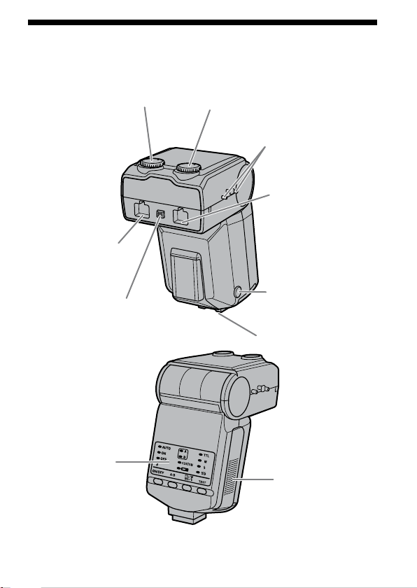
Name of parts
Macro Flash Controller
Manual-flash-control dial
(Twin flash B) (33)
Twin-flash-cord socket
(Twin flash B) (15) *
Manual-flash-control dial
(Twin flash A) (33)
Reel-attachment
points (18)
Twin-flash-cord socket
(Twin flash A) (15) *
Twin-flash-cord release
button (16)
Control panel (8)
Mounting-foot-release
button (13)
Mounting foot
Battery-chamber
door (11)
* Do not touch directly.
7
Page 8
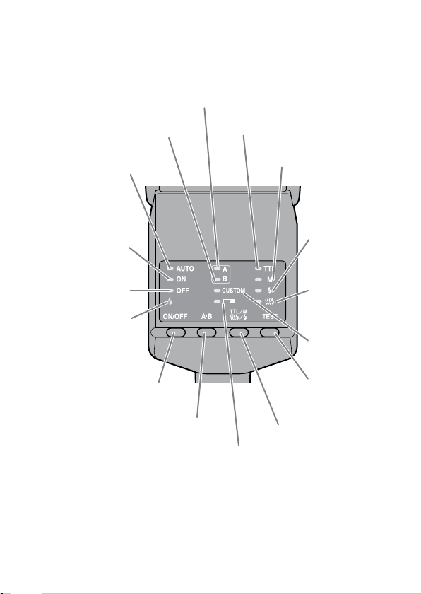
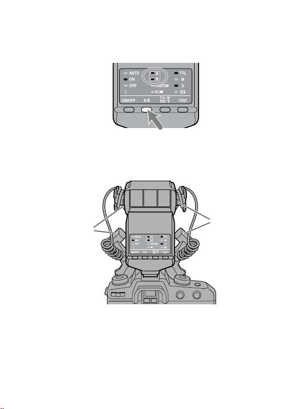
Control Panel
Twin flash A lamp (24)
Twin flash B lamp (24)
Auto lamp (31)
Flash-ON lamp (21)
Flash-OFF lamp (21)
Flash-ready lamp (25)
Flash ON/OFF button (21)
A-B button (Twin-flash A-B
selection button) (24)
TTL lamp (32)
Low-battery
lamp (12)
M (manual-flash-control)
lamp (32)
Test-flash lamp
(40)
Modeling-flash
lamp (41)
Custom lamp
(50)
TEST button (Test/
modeling flash button)
(40, 41)
TTL/M/Test button (TTL/M/
Test/Modeling flash mode
button) (32)
8
Page 9
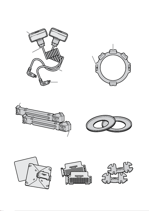
Macro Twin Flash
Twin Flash Unit*
Flashtube
Holder (14)
Shoe
Attachment
Connecting
cord
Plug
Release
tabs
Arm* (17)
Shoe
Base
Adaptor ring (14)
ø49mm, ø55mm
Diffuser* (44) Wide panel* (42) Cord reel* (18)
* Two supplied
9
Page 10
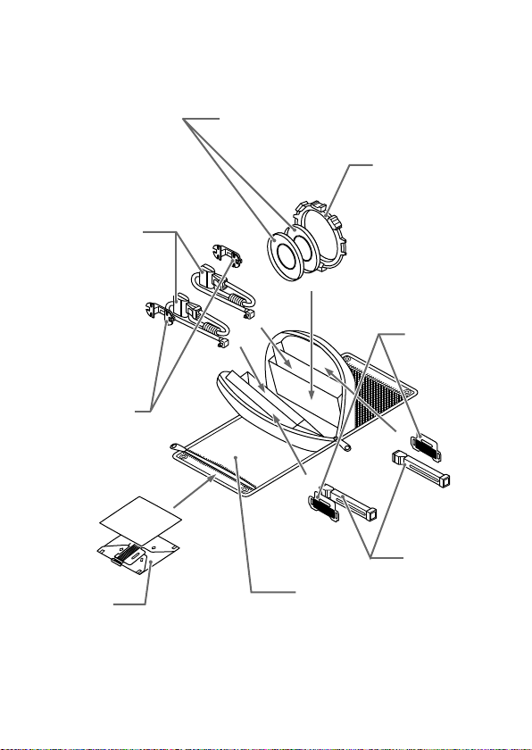
Example of storage
Adaptor ring ø49mm/ø55mm
Twin flash unit
Cord reel
Holder
Wide panel
Diffuser
10
Arm
Case
Page 11
Inserting batteries
Continued on the next page
e HVL-MT24AM may be powered by :
* Batteries are not supplied.
Four AA-size alkaline batteries
Four AA-size lithium batteries
Four AA-size rechargeable nickel-metal hydride (Ni-MH) batteries
Always ensure that rechargeable nickel-metal hydride batteries are charged in
the specied charger unit.
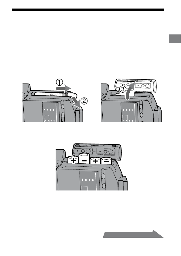
1 Open the battery-chamber door as shown.
2 Insert the batteries in the battery chamber as in the
diagram.
Preparations
3 Close the battery-chamber door.
Follow the reverse steps when opening the battery-chamber door.
e lamp on the control panel comes on. If it does not come on, press the ash
ON/OFF button.
11
Page 12
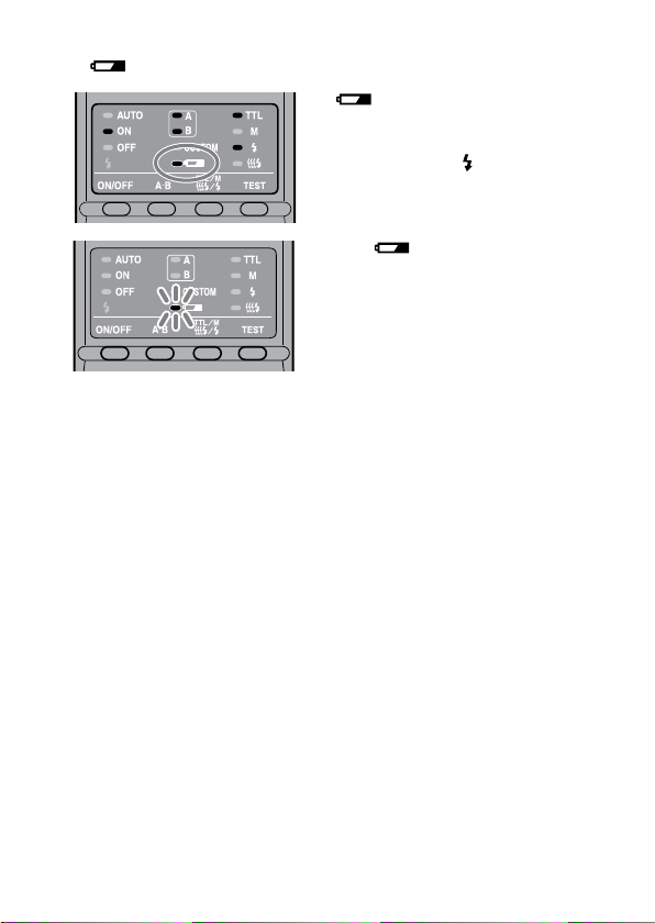
Checking Batteries
e lamp on the control panel comes on or blinks when the batteries are low.
lamp on
Changing the batteries is
recommended. e ash can still be
used in this state if (Flash-ready
lamp) on the rear of the unit is lit.
Only lamp blinking
Flash cannot be used.
Insert new batteries.
If nothing comes on when the ash ON/OFF button of the macro ash
controller is pressed, check the orientation of the batteries.
12
Page 13
Attachment and removal of the macro
1
2
flash controller
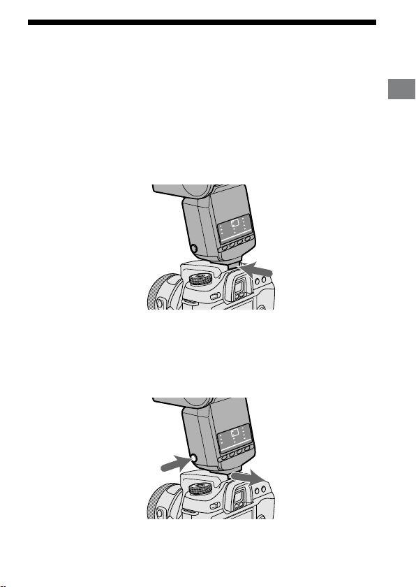
Attaching the macro flash controller to the
camera
Push the mounting foot firmly onto the camera until it stops.
e macro ash controller is locked in place automatically.
If the built-in ash in the camera is protruding, lower it before attaching the
macro ash controller.
Removing the macro flash controller from the
camera
While pressing the mounting foot release button , remove
the macro flash controller .
Preparations
13
Page 14
Attaching the macro twin flash
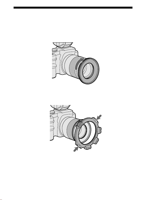
1 Screw the appropriate adaptor ring clockwise onto the
lens.
49mm and 55mm diameter adaptors are supplied.
2 While pressing the tabs on each side of the holder, place
the holder over the adaptor, and then release both tabs.
14
Page 15
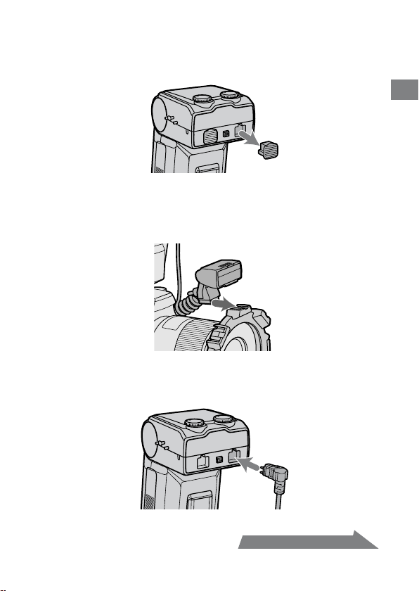
3 Remove the protective socket caps of the macro flash
Continued on the next page
controller.
For safe-keeping, place the caps in the case.
Replace caps aer use.
4 Place the twin flash unit into the shoe of one of the
holders.
Use of an arm is also possible (p. 17).
5 Insert the plug of the twin flash unit into the twin-flash-
cord socket on the macro flash controller.
Preparations
15
Page 16
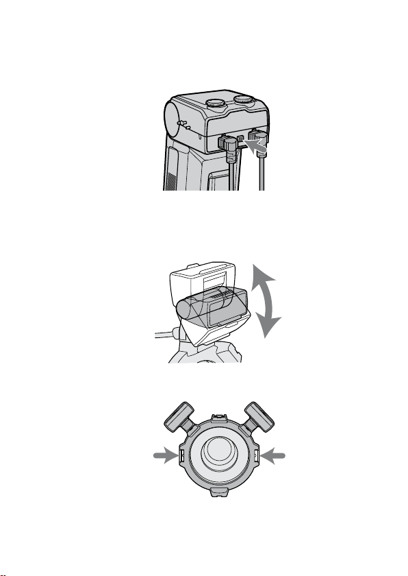
When removing the plug, press the twin flash-cord release
button on the macro flash controller and pull the plug
straight out of the socket.
Do not remove the plug by pulling on the connecting cord.
6 Adjust positions of the flashtubes as desired.
Each ashtube of the twin ash unit can be attached to any of the holder’s
four shoes.
Each ashtube of the twin ash unit can be tilted.
e holder can be rotated. Press the release tabs when removing or rotating
the holder.
16
Page 17
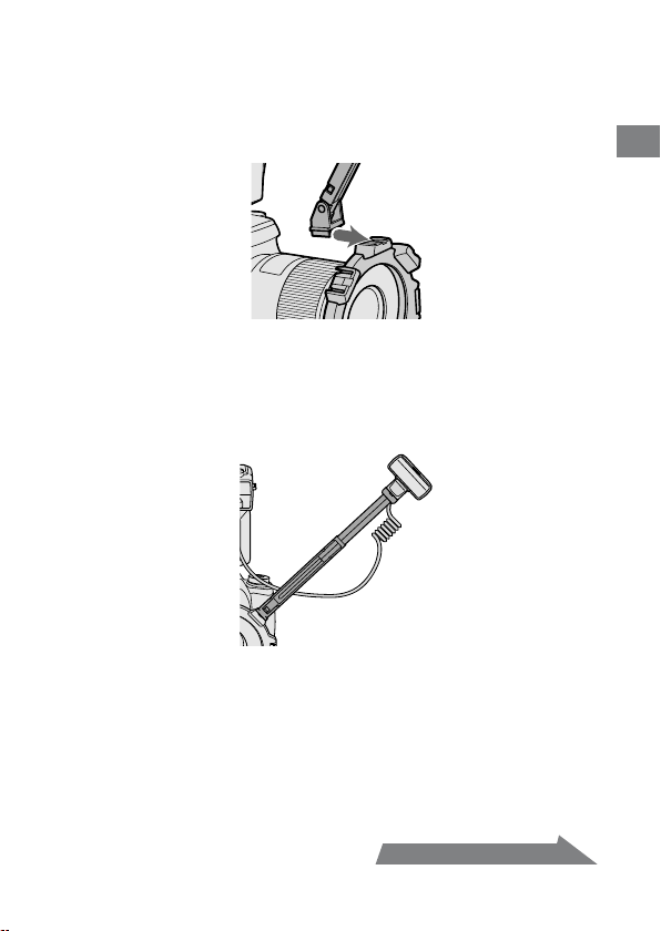
Attaching the arm
Continued on the next page
You can use an arm to position the ash unit away from the lens.
1 Attach the arm by sliding its base into one of the four
shoes on the holder.
2 Attach the flashtube of the twin flash unit to the shoe of
the arm.
3 Set the arm at either of two lengths.
Preparations
17
Page 18
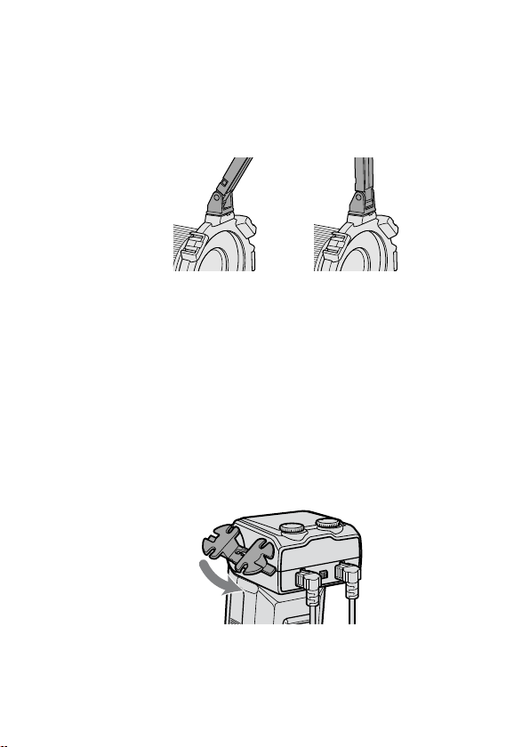
4 When changing the angle to 60° position, hold both ends
of the arm and move it so that it clicks twice into place.
e angle of the arm can be adjusted to either of two positions, 60° or 90°
position.
Although the arm can be moved past the 60° and 90° positions to prevent
breakage, only use in these two positions. Also, do not attach the two arms
in combination. Doing so may damage the arms.
60° position 90° position
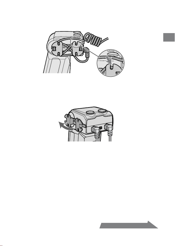
Using the cord reel
e cord reel can be attached to the side of the macro ash controller to take up
slack in the connecting cord of the twin ash unit.
Attaching the cord reel to the macro flash
controller
As illustrated, first check the up-down direction of the cord
reel, and then attach the top of the cord reel followed by the
bottom of the cord reel to the reel-attachment points on the
side of the macro flash controller.
18
Page 19
Example of taking up the connecting cord
Continued on the next page
Secure the connecting cord slack by wrapping it around the reel and using the
outer notches, as illustrated.
Removing the cord reel
Pull the bottom of the cord reel away from the macro flash
controller to remove it.
Preparations
19
Page 20
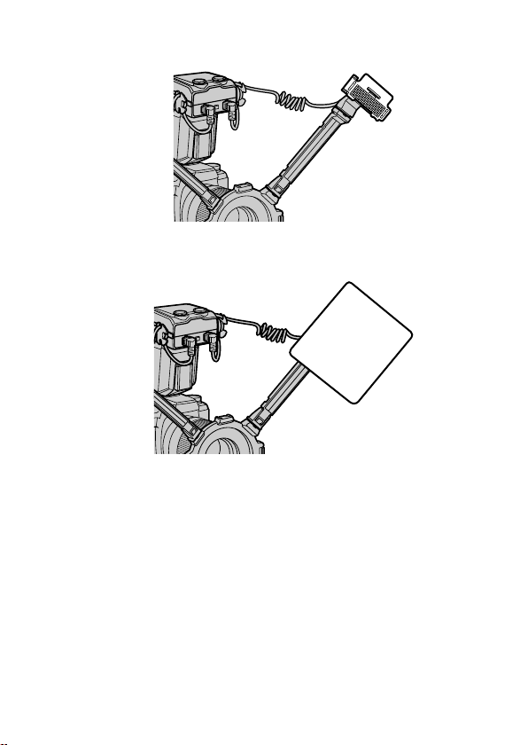
By attaching the wide panel to the ashtube, the ash coverage angle can be
increased (p. 42).
By using the diuser attached to the ashtube, strong shadows can be soened.
Always use the diuser with an arm (p. 44).
Make sure the ashtube is pointing at the subject. Do not allow the cord to get
in front of the ashtube or lens.
See page 51 for photographic examples.
If an arm is used when taking extreme close-ups with a 50mm F2.8 Macro lens,
the subject may not receive sucient lighting (p. 53).
20
Page 21
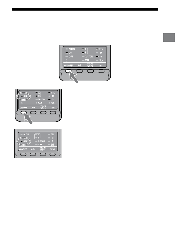
Auto power ON/OFF
Press the flash ON/OFF button on the back of the macro flash
controller.
Power of the macro ash controller comes on.
When the power of the macro ash controller
is turned on, the ash-ON lamp on the control
panel comes on.
If you press the ash ON/OFF button while the
macro ash controller is turned on, the macro
ash controller switches o and the ash-OFF
lamp on the control panel comes on.
e ash-OFF lamp goes out aer about 10
seconds.
Auto power off
If the camera or macro ash controller is not used for four minutes, the power
switches o and control panel indicators disappear automatically to save the
batteries.
You can disable auto power o or change the auto power o time by changing
the customized settings (p. 48).
Preparations
21
Page 22

Basic flash modes (A mode/M mode)
Camera’s exposure mode should be set to either A (aperture priority) mode*1, or M
(manual) mode*2.
In general close-up photography, the depth-of-eld*3 must be quite shallow,
which usually requires a smaller aperture when shooting. It is therefore better to
select A or M mode, which enable you to select the aperture.
Using a macro lens is also recommended.
In this section, the basic ash operation in A or M mode with TTL metering (TTL
lamp on) is described.
e following instructions from the next page assume that you are using one of
the following cameras and macro lenses.
Camera: A camera with A (aperture priority) mode or M (manual) mode.
Lens: 50mm F2.8 Macro
100mm F2.8 Macro
If you photograph in P mode, refer to page 30. If using a dierent lens, see the
aperture range graph on page 54.
*1 A mode: In A mode, you select the aperture and the camera
*2 M mode: You can select both aperture and shutter speed. You can select a
*3 Depth-of-eld: e range behind and in front of the subject that is sharply
automatically sets the shutter speed required for proper
exposure.
shutter speed that is slower than the camera’s sync speed.
focused. In close-up photography, this range is shallower and
the out-of-focus range is wider.
22
Page 23
1 Set the POWER switch of the camera to ON and select A or
Continued on the next page
M mode.
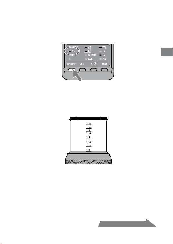
2 Press the flash ON/OFF button to turn on the flash-ON
lamp on the control panel.
3 Focus your subject and check the magnification ratio.
You can check the magnication ratio with the magnication ratio scale on
the lens. (e location of the magnication ratio scale diers depending on
the lens.)
4 When using M mode, select a shutter speed.
You cannot select the shutter speed faster than the camera’s sync speed.
Basics
5 Select the aperture.
To nd the correct aperture number, refer to pages 26 to 29.
23
Page 24
6 Select the flash.
Press the A-B button on the back of the macro ash controller to turn on the
twin ash A lamp, twin ash B lamp or both twin ash lamps. (e lit lamps
indicate which ash will go o.)
As viewed from the rear (control panel side), the A ash is connected to the le
side socket and the B ash to the right side socket.
For the eect of selecting the ash, see from page 51 to 53.
24
A flash
B flash
Page 25
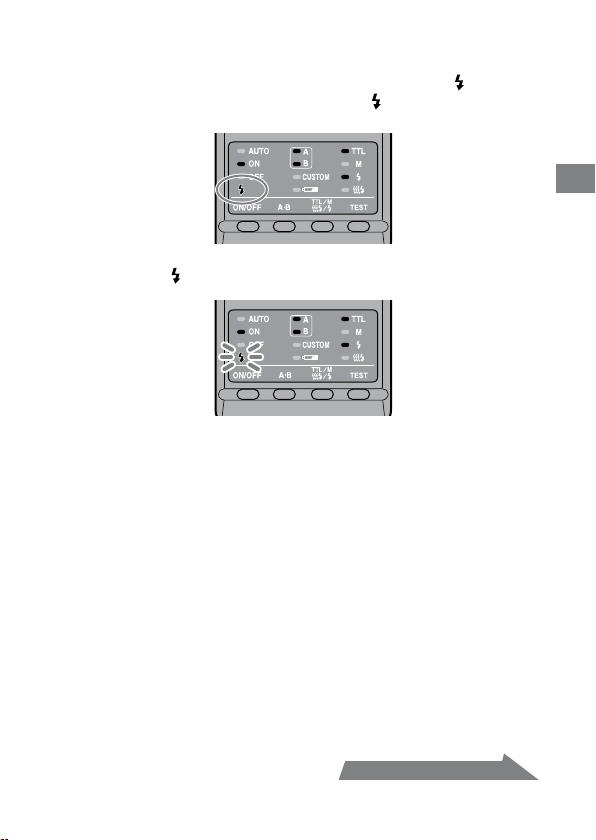
7 When the macro flash controller is charged, press the
Continued on the next page
shutter button to take a photo.
e macro ash controller is charged when the ash-ready lamp on the
control panel of the macro ash controller and the indicator in the camera
viewnder are both on.
When the correct exposure has been obtained for the photo just taken, the
ash-ready lamp on the control panel blinks.
e photo will be under-exposed if taken before charging is complete.
e use of a tripod or remote cord is recommended to reduce camera shake.
A camera-to-subject distance of less than 0.5m, and a magnication ratio of
more than 0.15X (greater than 1:7), are recommended to get the best results
from the macro ash units.
Always turn o the macro ash controller if the twin ash unit is not connected.
If the twin ash unit is not attached, but the controller is on, the camera ash
sync will be in eect and the resulting ambient exposures will be incorrect.
e camera’s AF illuminator is blocked by the adaptor ring or twin ash unit and
cannot be used for focusing.
Basics
25
Page 26

Selecting Apertures in TTL Flash
e following tables show values when ISO 100 is used without the wide panel
or diuser. For other ISO speeds, or if you use the wide panel or diuser, adjust
the aperture settings according to the tables on page 28.
e aperture ranges given in the tables are calculated values. e actual lens will
have its own usable aperture range.
Example: Using a 50mm F2.8 Macro lens when ISO 100, with a pair of
e following tables show data for certain lenses and magnication ratios. For
other lenses and magnication ratios, see page 54.
twin flash units with no arm, at a magnification ratio of 1:1
e range of acceptable apertures is calculated to be from f/4 to
f/90 (refer to the following table).
However, the lens aperture range is f/2.8 to f/32, so the actual
range possible with this lens is f/4 to f/32.
26
Page 27
Continued on the next page
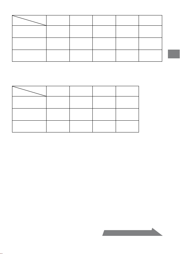
50mm F2.8 Macro (Lens aperture range : f/2.8 - f/32)
Magnication
Without arm
Arm (short)
60° position
Arm (long)
90° position
1:1 1:1.5 1:2 1:3 1:4
ratio
4 ~ 90
2.8 ~ 64
2.4 ~ 54
1.7 ~ 38
1.4 ~ 32
1 ~ 22
5.6 ~ 128
4 ~ 90
2.8 ~ 64
2 ~ 45
1.4 ~ 32
1 ~ 22
Upper set of numbers is for two twin ash units.
8 ~ 180
5.6 ~ 128
4 ~ 90
2.8 ~ 64
2 ~ 45
1.4 ~ 32
Lower set is for one twin ash unit.
5.6 ~ 128
4 ~ 90
4 ~ 90
2.8 ~ 64
2.4 ~ 54
1.7 ~ 38
100mm F2.8 Macro (Lens aperture range : f/2.8 - f/32)
Magnication
Without arm
Arm (short)
60° position
Arm (long)
90° position
1:1 1:1.5 1:2 1:3
ratio
3.5 ~ 76
2.4 ~ 54
2 ~ 45
1.4 ~ 32
1.2 ~ 27
0.85 ~ 19
Upper set of numbers is for two twin ash units.
3.5 ~ 76
2.4 ~ 54
2.8 ~ 64
2 ~ 45
1.7 ~ 38
1.2 ~ 27
Lower set is for one twin ash unit.
2.8 ~ 64
2 ~ 45
2.8 ~ 64
2 ~ 45
2 ~ 45
1.4 ~ 32
2.4 ~ 54
1.7 ~ 38
2.8 ~ 64
2 ~ 45
2 ~ 45
1.4 ~ 32
4.5 ~ 108
3.5 ~ 76
4.5 ~ 108
3.5 ~ 76
2.8 ~ 64
2 ~ 45
Basics
27
Page 28
When using other than ISO 100, or when using the wide panel
or diffuser
An additional adjustment must be applied to the previous tables.
Without wide
panel or diuser
(Exposure adjustment)
ISO 25 +2 Stop +3.5 Stop +4.5 Stop
ISO 50 +1 Stop +2.5 Stop +3.5 Stop
ISO 100 No change +1.5 Stop +2.5 Stop
ISO 200 –1 Stop +0.5 Stop +1.5 Stop
ISO 400 –2 Stop –0.5 Stop +0.5 Stop
ISO 800 –3 Stop –1.5 Stop –0.5 Stop
ISO 1600 –4 Stop –2.5 Stop –1.5 Stop
With wide panel
(Exposure adjustment)
With diuser
(Exposure adjustment)
f/stop scale
a full-stop
a half-stop
Decrease exposure Increase exposure
Using the f/stop scale
Using the f/stop scale at the le, moving
one step vertically is equal to a full-stop
change. Moving one step diagonally is
equal to a half-stop change.
Half a stop is basic for setting the
aperture in this step. When using a
0.3 stop setting camera, adjust the
aperture by a value as close as possible
to a value in the above table and use
the aperture around the f/stop scale.
For precise photography, bracketing is
recommended.
Example:
Starting at f/8, if you decrease the
exposure by a full stop, you get f/11.
If you increase by half a stop, you get
f/6.7.
28
Page 29

Selecting the aperture when using other than ISO 100, or
when using the wide panel or diffuser
1 Check the calculated acceptable aperture range under the same
condition with ISO 100 by using the table on page 27.
2 Check the additional adjustment when using other than ISO 100 or
when using the wide panel or diffuser by using the table on page 28.
3 Check the calculated acceptable aperture range by using the f/stop scale
using the results of step1 and step2.
4 Apply the result of step3 to the actual aperture range for this particular
lens and select the usable range for satisfactorily results.
Basics
Example: Using a 50mm F2.8 Macro lens, two twin flash units, no arm,
1 Check the calculated acceptable aperture range when using a 50mm F2.8 Macro
2 Check the additional adjustment when using ISO 200 and diuser by using the
Increase the aperture by +1.5 stops (refer to the table on page 28).
3 e aperture increased by +1.5 stops from f/8 is equal to f/4.5, and the aperture
4 e actual aperture range for a 50mm F2.8 Macro lens is f/2.8 - f/32, so the
magnification ratio of 1:2, and ISO 200
lens, two twin ash units, no arm, magnication ratio of 1:2, and ISO 100.
f/8 - f/180 (refer to the table on page 27)
table on page 28.
increased by +1.5 stops from f/180 is equal to f/108.
upper limit of the adjusted f/4.5 - f/108 range, i.e. f/108, is beyond the range that
can be set. e usable range for satisfactorily results is therefore f/4.5 - f/32.
29
Page 30
Program auto flash (The basics)
e procedure for P mode, including subject program selection, is the same as that
for A or M mode, except that the aperture is set automatically.
1 Set the POWER switch of the camera to ON and select P
mode.
2 Press the flash ON/OFF button to turn on flash-ON lamp on
the control panel.
3 Focus your subject and check the magnification ratio.
4 Select the flash.
5 When the macro flash controller is charged, press the
shutter button to take a photo.
30
Page 31

With some cameras, the ash will re automatically in P mode. In this case, the
auto lamp on the macro ash unit comes on and the ash may not re if the
surrounding conditions are bright.
e P mode ash program is designed for general subjects, not macro subjects.
When taking macro photos, the depth-of-eld may be very shallow. If the
aperture selected by the camera is outside the allowable range, the proper
exposure cannot be obtained (p. 26 - 29).
Basics
31
Page 32

32
Manual flash (M)
Normal TTL ash metering automatically adjusts the ash intensity to provide
the proper exposure for the subject. Manual ash provides a xed ash intensity
irrespective of the brightness of the subject and the camera setting.
In manual ash mode, the maximum ash power is when the manual ash
control is set to 1/1. Each step of the ash power level corresponds to one
aperture stop. Changing the setting by one stop, for example from 1/1 to 1/2, is
equivalent to decreasing the aperture one stop, for example from f/4 to f/5.6.
Manual ash can only be used when the camera is in the M mode. In other
modes, TTL measuring is automatically selected.
As manual ash is not aected by the reectivity of the subject, it is convenient
for use with subjects with extremely high or low reectivity.
TTL flash metering Manual flash metering
1 Select M mode on the camera.
2 Press the TTL/M/Test button to light on the M (manual-
flash control) lamp.
e modes change in the following order. (Test ash (p. 40), Modeling ash
(p. 41))
Page 33

TTL flash
Continued on the next page
Test flash
Manual flash
Test flash
TTL flash
Modeling flash
Manual flash
Modeling flash
3 Select shutter speed and aperture (p. 34 - 39).
4 Turn the appropriate manual-flash-control dial and select
the desired power level (p. 34 - 39).
When viewed from the rear (control panel side), the manual-ash-control
dial for twin ash A is on the le, and that for twin ash B is on the right.
You can select any power level setting on the upper scale from 1/1 to 1/64.
A flash B flash
In manual ash mode, if a proper exposure has been obtained, the ash-
ready lamp will not blink on the control panel aer a photo is taken.
Using customized functions, manual ash may be selected without setting
the camera in M mode. e size of the steps on the manual-ash-control
dials can also be changed from full-stop increments to half-stop increments
(p. 48).
Detailed operations
33
Page 34

34
Selecting apertures and power level in
manual flash
e following tables show the values when ISO 100 is used without the wide
panel or diuser. For other ISO speeds, or if you use the wide panel or diuser,
adjust the aperture settings according to the table on page 38. When using the
twin ash units, the data assumes that the power lever is the same for both units.
If they are set at dierent power levels, see page 37.
e aperture values given in the tables are calculated values. e actual lens will
have its own usable aperture range.
Example: Using a 50mm F2.8 Macro lens when ISO 100, with a pair
ese following tables show the apertures where the proper exposure of the
illuminated area is obtained. Actual exposure varies according to the subject’s
shape or position (p. 53). Test photographs or bracketing is recommended
especially when the subject is illuminated from side or behind.
e following tables show data for certain lenses and magnication ratios. For
other lenses and magnication ratios, see page 55.
of twin flash units with no arm, power level of 1/1, and a
magnification ratio of 1:1
e aperture is calculated at f/90 (refer to the following table).
However, the smallest actual aperture possible with this lens is
f/32.
erefore, if you set the power level to 1/1, the picture will be
overexposed.
But if you set the power level to 1/8, you will get a correct
exposure at f/32.
Page 35

50mm F2.8 Macro (Lens aperture range: f/2.8 - f/32)
Continued on the next page
Without
arm
Arm
(short)
60°
position
Arm
(long)
90°
position
Magnication ratio
Power level
1/1 90 (64) 128 (90) 180 (128) 128 (90) 108 (76)
1/2 64 (45) 90 (64) 128 (90) 90 (64) 76 (54)
1/4 45 (32) 64 (45) 90 (64) 64 (45) 54 (38)
1/8 32 (22) 45 (32) 64 (45) 45 (32) 38 (27)
1/16 22 (16) 32 (22) 45 (32) 32 (22) 27 (19)
1/32 16 (11) 22 (16) 32 (22) 22 (16) 19 (13)
1/64 11 (8) 16 (11) 22 (16) 16 (11) 13 (9.5)
1/1 54 (38) 64 (45) 90 (64) 90 (64) 108 (76)
1/2 38 (27) 45 (32) 64 (45) 64 (45) 76 (54)
1/4 27 (19) 32 (22) 45 (32) 45 (32) 54 (38)
1/8 19 (13) 22 (16) 32 (22) 32 (22) 38 (27)
1/16 13 (9.5) 16 (11) 22 (16) 22 (16) 27 (19)
1/32 9.5 (6.7) 11 (8) 16 (11) 16 (11) 19 (13)
1/64 6.7 (4.5) 8 (5.6) 11 (8) 11 (8) 13 (9.5)
1/1 32 (22) 32 (22) 45 (32) 54 (38) 64 (45)
1/2 22 (16) 22 (16) 32 (22) 38 (27) 45 (32)
1/4 16 (11) 16 (11) 22 (16) 27 (19) 32 (22)
1/8 11 (8) 11 (8) 16 (11) 19 (13) 22 (16)
1/16 8 (5.6) 8 (5.6) 11 (8) 13 (9.5) 16 (11)
1/32 5.6 (4) 5.6 (4) 8 (5.6) 9.5 (6.7) 11 (8)
1/64 4 (2.8) 4 (2.8) 5.6 (4) 6.7 (4.5) 8 (5.6)
Use aperture values inside ( ) when only one twin ash unit is used.
1:1 1:1.5 1:2 1:3 1:4
Detailed operations
35
Page 36

36
100mm F2.8 Macro (Lens aperture range: f/2.8 - f/32)
Magnication ratio
Power level
1/1 76 (54) 76 (54) 64 (45) 54 (38)
1/2 54 (38) 54 (38) 45 (32) 38 (27)
Without
arm
Arm
(short)
60°
position
Arm
(long)
90°
position
Use aperture values inside ( ) when only one twin ash unit is used.
1/4 38 (27) 38 (27) 32 (22) 27 (19)
1/8 27 (19) 27 (19) 22 (16) 19 (13)
1/16 19 (13) 19 (13) 16 (11) 13 (9.5)
1/32 13 (9.5) 13 (9.5) 11 (8) 9.5 (6.7)
1/64 9.5 (6.7) 9.5 (6.7) 8 (5.6) 6.7 (4.5)
1/1 45 (32) 64 (45) 64 (45) 64 (45)
1/2 32 (22) 45 (32) 45 (32) 45 (32)
1/4 22 (16) 32 (22) 32 (22) 32 (22)
1/8 16 (11) 22 (16) 22 (16) 22 (16)
1/16 11 (8) 16 (11) 16 (11) 16 (11)
1/32 8 (5.6) 11 (8) 11 (8) 11 (8)
1/64 5.6 (4) 8 (5.6) 8 (5.6) 8 (5.6)
1/1 27 (19) 38 (27) 45 (32) 45 (32)
1/2 19 (13) 27 (19) 32 (22) 32 (22)
1/4 13 (9.5) 19 (13) 22 (16) 22 (16)
1/8 9.5 (6.7) 13 (9.5) 16 (11) 16 (11)
1/16 6.7 (4.5) 9.5 (6.7) 11 (8) 11 (8)
1/32 4.5 (3.5) 6.7 (4.5) 8 (5.6) 8 (5.6)
1/64 3.5 (2.4) 4.5 (3.5) 5.6 (4) 5.6 (4)
1:1 1:1.5 1:2 1:3
Page 37

When twin flash units are at different power level settings
192+ 132= 361 + 169 = 530 22
Continued on the next page
e values given in the preceding tables for the twin ash units assume that both
twin ash units are set at the same ash level.
When they are set to dierent ash power levels, the aperture needed for correct
exposure can be calculated using the following equation:
Aperture*
(A ash aperture)2 + (B ash aperture)
=
Example:
Using a 100mm F2.8 Macro lens with a pair of twin flash units with no
arm, “A” flash is set at a power level of 1/8, “B” flash unit is set at 1/16, and
the magnification ratio is 1:1
e A ash aperture set at a power level of 1/8 is f/19 and the B ash aperture set
at a power level of 1/16 is f/13 (refer to the table on 36 page).
Apply these results in the above equation.
erefore, in the above example, an aperture setting of f/22 will give proper
exposure.
* When both twin ash units are used.
2
Detailed operations
37
Page 38

38
When using other than ISO 100, or when using the wide panel
or diffuser
An additional adjustment must be applied to the previous tables.
Without wide
panel or diuser
(Exposure adjustment)
ISO 25 +2 Stop +3.5 Stop +4.5 Stop
ISO 50 +1 Stop +2.5 Stop +3.5 Stop
ISO 100 No change +1.5 Stop +2.5 Stop
ISO 200 –1 Stop +0.5 Stop +1.5 Stop
ISO 400 –2 Stop –0.5 Stop +0.5 Stop
ISO 800 –3 Stop –1.5 Stop –0.5 Stop
ISO 1600 –4 Stop –2.5 Stop –1.5 Stop
With wide panel
(Exposure adjustment)
With diuser
(Exposure adjustment)
f/stop scale
a full-stop
a half-stop
Decrease exposure Increase exposure
Using the f/stop scale
Using the f/stop scale at the le, moving
one step vertically is equal to a full-stop
change. Moving one step diagonally is
equal to a half-stop change.
Half a stop is basic for setting the
aperture in this step. When using a
0.3 stop setting camera, adjust the
aperture by a value as close as possible
to a value in the above table and use
the aperture around the f/stop scale.
For precise photography, bracketing is
recommended.
Example:
Starting at f/8, if you decrease the
exposure by a full stop, you get f/11.
If you increase by half a stop, you get
f/6.7.
Page 39

Selecting the aperture when using other than ISO 100, or
when using the wide panel or diffuser
Check the calculated acceptable aperture under the same condition with
1
ISO 100 by using the table on pages 35 and 36.
Check the additional adjustment when using other than ISO 100 or
2
when using the wide panel or diffuser by using the table on page 38.
Select the calculated acceptable aperture by using the f/stop scale using
3
the results of step1 and step2.
Example: Using a 100mm F2.8 Macro lens, two twin flash units, no arm, a
1 Check the calculated acceptable aperture when using a 100mm F2.8 Macro lens,
2 Check the additional adjustment when using ISO 200 and diuser by using the
Increase the aperture by +1.5 stops (refer to the table on page 38).
3 e aperture increased by +1.5 stops from f/38 is equal to f/22.
power level of 1/4, magnification ratio of 1:1, ISO 200 with the
diffuser
two twin ash units, no arm, a power level of 1/4, magnication ratio of 1:1, and
ISO 100.
f/38 (refer to the table on page 36)
table on page 38.
Detailed operations
39
Page 40

40
Test flash
You can try one test ash before shooting. Use test ash mode when using a ash
meter in manual-ash mode.
1 Press the TTL/M/Test button to turn on the test-flash lamp
.
Each time the TTL/M/Test button is pressed to change the TTL and M lamp
be sure to check that the appropriate lamp is on. (See page 33 for the display
sequence.)
2 Press the TEST button (test/modeling flash button) .
With TTL ash metering, the test ash will re at full power when the
TEST button is pressed.
In manual ash mode, the test ash will re at the selected power level
when the TEST button is pressed. When using a ash meter, use manual
ash mode.
Page 41

Modeling flash
You can try continuous ash to check for shadows on the subject before shooting.
e ash will re for two seconds at a rate of 40 ashes per second.
1 Press the TTL/M/Test button to turn on the modeling-flash
lamp .
Each time the TTL/M/Test button is pressed to change the TTL and M lamp
be sure to check that the appropriate lamp is on. (See page 33 for the display
sequence.)
2 Press the TEST button (test/modeling flash button) .
Do not press the shutter button while the ash is in use.
e strength of shadows will dier from that during actual photography.
When using the ash in a bright place or outdoors or when using a bounce
ash, shadows are lighter so verication is more dicult.
Detailed operations
41
Page 42

42
Wide panel
e twin ash unit has a coverage of 60° horizontally and 45° vertically (equivalent
to a lens with a 35mm focal length). By attaching the wide panel, the angles are
increased to 78° horizontally and 60° vertically (equivalent to a lens with a 24mm
focal length).
With wide panel
Without wide panel
Attaching the wide panel
1 Check the front side of the wide panel.
Front side
2 Align the lower edge of the wide panel to the projection on
the side of the flashtube and press the wide panel.
Press the wide panel until it clicks into place.
Page 43

Removing the wide panel
Hold the top tab of the wide panel and remove it forwards
while pressing downward slightly.
e ash output is reduced when using the wide panel. See page 28 for TTL ash
metering and page 38 for manual ash metering.
Detailed operations
43
Page 44

44
Diffuser
Strong shadows can be soened by attaching the diuser to the ashtube. Always
use the diuser with an arm to prevent it appearing in the image.
Example:
With diffuser Without diffuser
Using the diffuser
1 Unclip the panel from the diffuser.
This side cannot be
detached.
Page 45

2 As illustration, slide the tab through the slot near the clip.
Continued on the next page
The dimple above the slot should slide fit into the hole in
the tab.
3 Place the four side tabs into the slot on the side of the
diffuser.
On the other side, in the same way, place the four side tabs into the slots.
If it is dicult to assemble the diuser, fold it up and try again.
Detailed operations
Note
Do not force or pull hard on the diuser. Do not fold the diuser inside out.
45
Page 46

46
4 While holding the diffuser by its panel’s top tab, press it
against the face of the twin flash unit.
Press the diuser until it clicks into place.
Notes on using the diffuser
If the arm is set at the 60° position and used with a wide angle lens, the diuser
may appear in the image. It is recommended that you always use the diuser
with the arm set at the 90° position.
e ash output is reduced when using the diuser. See page 28 for TTL ash
metering, or page 38 for manual ash metering.
Page 47

Removing the diffuser
1 Remove the diffuser while holding its panel’s top tab.
2 Pull the tab off the dimple as illustration. The diffuser can
now be easily removed.
3 Refold the diffuser and secure it by clipping the panel to it.
Detailed operations
47
Page 48

48
Custom setting
e various ash settings can be changed as necessary.
e following three items may be changed.
Time to auto power o (4 minutes/15 minutes/60 minutes/None)
Recording modes in which manual ash may be set
(M mode only/All modes)
Manual-ash power-level steps (1EV increments / 1/2EV increments)
1 Press the flash ON/OFF button for three seconds.
e auto lamp, ash-ON lamp and ash-OFF lamp all come on together, and
the item (time to auto power o) is displayed.
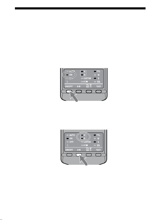
2 Press the A-B button (twin-flash A-B selection button) to
select the item, and press the TTL/M/Test button to select
the desired setting.
Each time the A-B button is pressed, the above three items appear on the
control panel (see following page).
Page 49

Continued on the next page
1.Time to auto power off
4 minutes 15 minutes
M mode only All modes
1EV increments 1/2EV increments
60 minutes None
2. Recording modes in which manual flashmay be set
3. Manual-flash power-level steps
Selec t using the T TL/M/Test but ton
Selec t using the A-B button
Detailed operations
49
Page 50

3 After making your selections, press the flash ON/OFF
button to return to exit the custom mode.
When a setting other than the default setting is selected in custom mode,
the custom lamp on the control panel comes on.
When “All modes” is selected (see 2. Recording modes in which manual
ash may be set), manual ash may be used in all recording modes.*
* e proper exposure may not be obtained in modes other than M mode.
Using M mode is therefore recommended.
If “1/2 EV steps” is selected in item 3, use the gray power values provided
on the lower scale of the manual-ash-control dials. e half-stop values
are not written on the scale.
e power values are1/1, 1/1.4, 1/2, 1/2.8, 1/4, 1/5.6, and 1/8.
e selected settings are maintained even when the ash unit is turned o
or the battery removed.
50
Page 51

Examples of macro twin flash
Continued on the next page
photography
By using this macro twin ash, you can change the position and angle of the twin
ash unit to achieve more expressive lighting.
Example:
Top light only Side light only Top and side light
Strong shadows of the subjects can be soened by using the diuser attached to the
ashtube (p. 44).
Example:
Additional Information
Top light with diffuser
51
Page 52

Two twin flash shooting with arms
To accent detail and give depth, illuminate the subject from the sides using the
arms.
Example:
With arms from the sides
Without arms from the front
52
Page 53

Note
If a close-up subject is illuminated from the side using an arm, strong shadows may
occur. Strong ash illumination from behind the subject can cause aring.
is condition is particularly likely to occur with a 50mm F2.8 Macro lens with
ashtubes mounted on arms.
Example:
With arms from the sides
Without arms from the front
Additional Information
53
Page 54

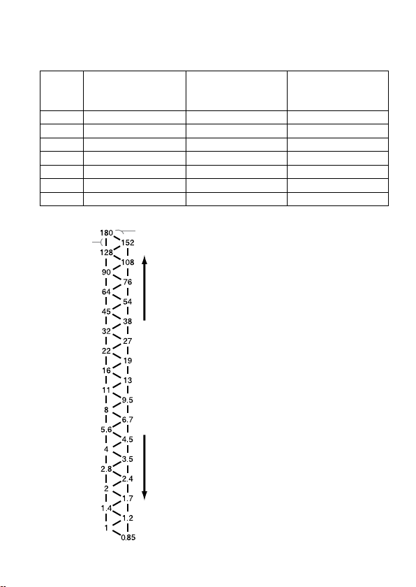
Aperture range graph
Flash-subject
distance
Min. Aperture lines
Aperture
Max. Aperture lines
Min. Aperture lines
Max. Aperture lines
e aperture range for macro lenses is displayed on page 26 (TTL), and page 34
(Manual ash). e aperture ranges described here are for lenses other than macro
lenses, or when the subject distance is large.
TTL flash metering
e following explains how to obtain the aperture range using the two twin ash
units with a 1.5 m ash-to-subject distance and at ISO 100.
1 Draw a vertical line upwards from the ash-to-subject distance until it reaches
the minimum aperture line ().
2 Draw a horizontal line lewards from until it reaches the vertical ISO line
corresponding to the camera used ().
3 Draw a diagonal line from upwards and lewards. e result indicates the
minimum aperture that will provide the proper exposure ().
4 e maximum aperture can be obtained in the same way by using the maximum
aperture line ().e results of both calculations will give the usable aperture
range for obtaining the proper exposure ().
In this case, the proper exposure can be obtained by setting the camera’s aperture
from maximum to f/16.
e dotted lines are employed when only one twin ash unit is used.
54
Page 55

Manual flash metering
Flash-subject
distance
Aperture
Flash power lineFlash power line
1/1
1/2 (1/1)
1/4 (1/2)
1/8 (1/4)
1/16 (1/8)
1/32 (1/16)
1/64 (1/32)
(1/64)
1/1
1/2 (1/1)
1/4 (1/2)
1/8 (1/4)
1/16 (1/8)
1/32 (1/16)
1/64 (1/32)
(1/64)
e following explains how to obtain the aperture using the two twin ash units
with a power level of 1/1 at 1.5 m ash-to-subject distance and at ISO 100.
1 Draw a vertical line upwards from the ash-to-subject distance until it reaches
the ash power line that corresponds to the set power level ().
2 Draw a horizontal line lewards from until it reaches the vertical ISO line
corresponding to the camera used ().
3 Draw a diagonal line from upwards and lewards. e result indicates the
aperture that will provide the proper exposure ().
In this case, the proper exposure can be obtained by setting the camera’s aperture
to f/16.
e gures in parenthesis are employed when only one twin ash unit is used.
Additional Information
55
Page 56

Compatibility with other products
Lens
49 mm and 55 mm adaptor rings are supplied.
Lenses whose barrels rotate when auto-focusing cannot be used.
When a wide angle lens is used, part of the holder may appear in the image. Do
not use lenses whose focal length is shorter than 24 mm. If the focal length is
between 24 mm and 27 mm, contact an authorized Sony dealer.
If using a lter at a focal length of less than 50 mm, part of the holder may
appear in the image.
56
Page 57

Notes on use
Continued on the next page
While shooting
is ash unit generates strong light, so it should not be used directly in front of
the eyes.
Batteries
Do not store the macro ash controller with the alkaline batteries inside it.
Leakage from the batteries may damage the battery chamber.
Depending on the temperature or storage conditions, the battery level displayed
may be lower than the actual battery capacity. e displayed battery level is
restored to the correct value aer the ash has been used a few times. When
lamp blinks to indicate that the ash cannot be used, pressing the ash
ON/OFF button a number of times may result in restoration of the correct
battery level display. If the battery level is still not restored, replace the battery.
When using lithium batteries, if the batteries become hot due to high
temperature or continuous use, lamp may blink and the ash may not
work for a while. Wait for the batteries to cool down before using the ash again.
Nickel-metal hydride batteries can lose power suddenly. If lamp starts
blinking or the ash can no longer be used while taking pictures, change or
recharge the batteries.
e ash frequency and number of ashes provided by new batteries may
vary from the values shown in the table, depending on the time elapsed since
manufacture of the batteries.
Additional Information
57
Page 58

Temperature
e ash unit may be used over a temperature range of 0 °C to 40 °C.
Do not expose the ash unit to extremely high temperatures (e.g. in direct
sunlight inside a vehicle) or high humidity.
To prevent condensation forming on the ash, place it in a sealed plastic bag
when bringing it from a cold environment into a warm environment. Allow it to
reach room temperature before removing it from the bag.
Battery capacity decreases at colder temperatures. Keep your camera and spare
batteries in a warm inside pocket when shooting in cold weather. lamp
may light on even when there is some power le in the batteries in cold weather.
Batteries will regain some of their capacity when warmed to normal operating
temperature.
is ash unit is not waterproof. Be careful not to bring it into contact with
water or sand when using it at the seashore, for example. Contact with water,
sand, dust, or salt may result in a malfunction.
Maintenance
Remove this unit from the camera. Clean the ash with a dry so cloth. If the
ash has been in contact with sand, wiping will damage the surface, and it should
therefore be cleaned gently using a blower. In the event of stubborn stains, use a
cloth lightly dampened with a mild detergent solution, and then wipe the unit clean
with a dry so cloth. Never use strong solvents, such as thinner or benzene, as
these damage the surface nish.
58
Page 59

Specifications
Continued on the next page
Guide number
Frequency/Repetition
Flash coverage
Normal ash (ISO 100)
Power
level
1/1 17 24 11 7
1/2 12 17 8 5
1/4 8.5 12 5.6 3.5
1/8 6 8.5 4 2.5
1/16 4.2 6 2.8 1.8
1/32 3 4.2 2 1.3
1/64 2.1 3 1.4 0.9
Wide panel and diuser is for one tube.
Frequency (sec) 0.2~6 0.2~6 0.2~5
Repetition (times) 200~4000 500~10000 150~3000
Repetition is the approximate number of times that are possible
before a new battery is completely dead.
Flash
coverage
Vertical 45° 60° 90°
Horizontal 60° 78° 90°
1 tube 2 tubes
Alkaline Lithium
Twin
ash
Wide
panel
Wide
panel
Diuser
Additional Information
Nickel-
hydride
(1550 mAh)
Diuser
59
Page 60

Continuous ash performance
40 ashes at 5 ashes per second
(Power level 1/32, nickel-metal hydride battery)
Flash control Flash control using pre-ash, TTL direct metering,
Manual ash
Dimension (Approx.)
Macro ash controller
68 × 123 × 91 mm (2 3/4 × 4 7/8 × 3 5/8 in.) (w × h × d)
Twin ash unit
43 × 41 × 37 mm (1 3/4 × 1 5/8 × 1 1/2 in.) (w × h × d)
Mass (Approx.) Macro ash controller 235 g (8.3 oz.) (without batteries)
Twin ash unit 33 g (1.2 oz.) (per twin ash unit)
Operating temperature
0 °C to 40 °C (32 °F to 104 °F)
Included items Macro ash controller (1), Twin ash unit (2), Holder (1),
Arm (2), Adaptor ring ø 49mm (1),
Adaptor ring ø 55mm (1), Wide panel (2), Diuser (2),
Cord reel (2), Controller case (1), Flash case (1),
Set of printed documentation
Functions in these operating instructions depend on testing conditions at our rm.
Design and specications are subject to change without notice.
60
Page 61

Trademark
is a trademark of Sony Corporation.
61
Page 62

2
Português
Antes de utilizar o produto, leia este manual até ao m e guarde-o para consultas
futuras.
AVISO
Para reduzir o risco de incêndio ou choque eléctrico, não exponha a unidade à
chuva ou à humidade.
Quando deitar fora as pilhas, coloque ta adesiva nos terminais das pilhas de
lítio para evitar que entrem em curto-circuito e cumpra os regulamentos locais
aplicáveis.
Não deixe as pilhas ou objectos que possam ser engolidos ao alcance das crianças.
Em caso de ingestão, contacte imediatamente um médico.
Retire imediatamente as pilhas e deixe de utilizar se...
ash cair ou for submetido a um choque que deixe a descoberto os componentes
internos.
ash deitar um cheiro estranho, fumo ou aquecer demais.
Não desmonte. Pode receber uma descarga eléctrica se tocar num dos circuitos de
alta tensão do interior do aparelho.
Page 63

Para os clientes na Europa
Tratamento de Equipamentos Eléctricos e Electrónicos no
nal da sua vida útil (Aplicável na União Europeia e em países
Europeus com sistemas de recolha selectiva de resíduos)
Este símbolo, colocado no produto ou na sua embalagem, indica
que este não deve ser tratado como resíduo urbano indiferenciado.
Deve sim ser colocado num ponto de recolha destinado a resíduos
de equipamentos eléctricos e electrónicos. Assegurando-se que
este produto é correctamente depositado, irá prevenir potenciais
consequências negativas para o ambiente bem como para a saúde,
que de outra forma poderiam ocorrer pelo mau manuseamento
destes produtos. A reciclagem dos materiais contribuirá para a
conservação dos recursos naturais. Para obter informação mais
detalhada sobre a reciclagem deste produto, por favor contacte o
município onde reside, os serviços de recolha de resíduos da sua
área ou a loja onde adquiriu o produto.
Marca comercial
é uma marca comercial da Sony Corporation.
3
Page 64

4
Índice
Características ............................... 5
Nomes das peças ........................... 6
Preparativos
Colocar as pilhas ......................... 10
Montar e desmontar o controlador
do ash para macro .................... 12
Montar o ash duplo .................. 13
Ligar/desligar automaticamente
....................................................... 20
Modos básicos
Modos básicos do ash
(Modo A/Modo M) .................... 21
Programar o ash automático
(noções básicas) .......................... 29
Operações detalhadas
Flash manual (M) ....................... 31
Teste do ash ............................... 39
Flash de modelação .................... 40
Painel de alargamento ................ 41
Difusor ......................................... 43
Regulações personalizadas ........ 47
Informações adicionais
Exemplos de fotograas tiradas
com o ash duplo de macro ...... 50
Gráco de intervalo de aberturas
....................................................... 53
Compatibilidade com outros
produtos ......................................55
Notas sobre a utilização ............. 56
Manutenção ................................. 57
Características técnicas .............. 58
Page 65

Antes de utilizar
Para obter mais informações, consulte o manual de instruções fornecido com a
máquina.
Este ash não é à prova de pó, salpicos ou água.
Não coloque o ash em nenhum dos locais indicados a seguir.
Não guarde nem utilize o ash em nenhum dos locais indicados abaixo. Se o zer,
pode provocar uma avaria.
Não coloque o ash num local exposto à luz solar directa, como no tablier
de um automóvel ou perto de um aquecedor pois pode car deformado ou
funcionar mel.
Locais com muitas vibrações
Locais com muito electromagnetismo
Locais com muita areia
Na praia e em locais com muita areia ou onda possa haver nuvens de pó, proteja
o ash da areia e do pó.
Se não o zer, pode provocar uma avaria.
Características
O kit de ash duplo para macro oferece uma iluminação exível para fotografar
cenas da natureza em macro. É ideal para fotografar de perto ores, insectos,
objectos pequenos, etc.
A possibilidade de mudar a posição e o ângulo de montagem do tubo do ash
permite fazer fotograas mais expressivas.
Se montar braços reguláveis de dois comprimentos entre o ash duplo e os
suportes pode alterar a iluminação quando fotografar de perto com um grau de
ampliação muito grande.
Utilizando o difusor fornecido pode também obter uma iluminação mais suave.
O painel de alargamento fornecido aumenta a distância de alcance do ash para
uma distância focal de 24 mm.
A função de ash de modelação permite ver ainda melhor as sombras antes de
tirar a fotograa.
5
Page 66

6
Nomes das peças
Controlador do ash para macro
Botão de controlo de ash
manual
(Flash duplo B) (32)
Tomada para o cabo do
ash duplo
(Flash duplo B) (14) *
Botão de libertação dos
cabos do ash duplo
(15)
Botão de controlo de ash
manual (Flash duplo A) (32)
Base de encaixe
Pontos de montagem
do enrolador (17)
Tomada para o cabo do
ash duplo
(Flash duplo A) (14) *
Botão de libertação da
base de encaixe (12)
Painel de controlo
(7)
Tampa do
compartimento das
pilhas (10)
* Não toque directamente.
Page 67

Painel de controlo
Indicador do ash duplo A (23)
Indicador do ash duplo B (23)
Indicador do modo
automático (30)
Indicador de ash
ligado (ON) (20)
Indicador de ash
desligado (OFF) (20)
Indicador de ash
carregado (24)
Botão ON/OFF do ash (20)
Botão A-B (Botão de selecção
do ash duplo A ou B) (23)
Indicador TTL (31)
Indicador de
pilha fraca (11)
Indicador M (controlo
manual do ash) (31)
Indicador de teste
do ash (39)
Indicador de ash
de modelação (40)
Indicador de
personalização (49)
Botão TEST (Botão
de Teste/Flash de
modelação) (39, 40)
Botão Teste/TTL/M (Botão
do modo TTL/M/Teste/Flash
de modelação) (31)
7
Page 68

8
Kit de ash duplo
Flash duplo*
Tubo de ash
Encaixe de
montagem
Braço de extensão* (16)
Base de encaixe no suporte
Cabo de
ligação
Ficha
Base
Suporte (13)
Patilhas de
libertação
Base de encaixe do
braço de extensão
Anel adaptador (13)
ø49mm, ø55mm
Difusor* (43) Painel de
alargamento* (41)
Enrolador do
cabo* (17)
* São fornecidos dois
Page 69

Exemplo de arrumação do ash
Anel adaptador ø49mm ø55mm
Flash duplo
Enrolador
do cabo
Suporte
Painel de
alargamento
Difusor
Braço de
extensão
Estojo
9
Page 70

10
Colocar as pilhas
O HVL-MT24AM pode ser alimentado por:
*As pilhas não são fornecidas.
Quatro pilhas alcalinas tamanho AA
Quatro pilhas de lítio tamanho AA
Quatro pilhas recarregáveis de hidreto de metal de níquel tamanho AA (Ni-
MH)
Verique sempre se as pilhas recarregáveis de hidreto de metal de níquel foram
carregadas no carregador especicado.
1 Abra a porta do compartimento das pilhas como se mostra
na gura.
2 Introduza as pilhas no compartimento como se mostra no
diagrama.
3 Feche a porta do compartimento das pilhas.
Siga os passos pela ordem inversa quando abrir a porta do compartimento das
pilhas.
O indicador do painel de controlo acende-se. Se não se acender, carregue no
botão ON/OFF do ash.
Page 71

Vericar as pilhas
O indicador do painel de controlo acende-se ou pisca quando as pilhas
estiverem fracas.
Indicador aceso
Deve substituir as pilhas. Pode
continuar a utilizar o ash se
(indicador de ash carregado) na
parte de trás do ash estiver aceso.
Só pisca o indicador
Não pode utilizar o ash.
Coloque pilhas novas.
Se não aparecer nada quando carregar no botão ON/OFF do controlador do
ash para macro, verique o sentido de colocação das pilhas.
Preparativos
11
Page 72

12
Montar e desmontar o controlador do
1
2
ash para macro
Montar o controlador do ash para macro na
máquina
Faça deslizar com rmeza a base de montagem na máquina
até ao m.
O controlador do ash para macro xa-se automaticamente no lugar respectivo.
Se o ash interno da máquina estiver levantado, baixe-o antes de montar o
controlador do ash para macro.
Desmontar o controlador do ash para macro
da máquina
Carregue no botão de libertação da base de montagem e
retire o controlador do ash para macro .
Page 73

Montar o ash duplo
Continua na página seguinte
1 Aparafuse o anel adaptador adequado na objectiva
rodando-o no sentido dos ponteiros do relógio.
São fornecidos adaptadores com 49mm e 55mm de diâmetro.
2 Enquanto carrega nas patilhas laterais do suporte, coloque
este último no adaptador e depois solte as patilhas.
Preparativos
13
Page 74

14
3 Retire as tampas de protecção das tomadas de encaixe do
controlador do ash para macro.
Guarde as tampas no estojo para não as perder.
Depois de utilizar volte a colocar as tampas.
4 Coloque o ash duplo na base de encaixe de um dos
suportes.
Também pode utilizar um braço de extensão (p. 16).
5 Ligue a cha do ash duplo à tomada para cabo respectiva
do controlador de ash para macro.
Page 75

Continua na página seguinte
Para desligar a cha, carregue no botão de libertação do
cabo do ash duplo do controlador de ash e puxe a cha
a direito para fora da tomada.
Não desligue a cha puxando pelo cabo.
6 Ajuste os tubos de ash para as posições desejadas.
Pode montar cada um dos tubos de ash do ash duplo em qualquer uma
das quatro bases de montagem do suporte.
Pode inclinar cada um dos tubos de ash do ash duplo individualmente.
O suporte é rotativo. Para retirar ou rodar o suporte carregue nas patilhas
de libertação.
Preparativos
15
Page 76

16
Montar o braço de extensão
Pode utilizar um braço de extensão para posicionar o ash afastado da objectiva.
1 Monte o braço fazendo deslizar a base respectiva para
dentro de uma das quatro bases de montagem do suporte.
2 Monte o tubo de ash duplo na base de encaixe do braço
de extensão.
3 Regule o braço de extensão para um dos dois
comprimentos possíveis.
Page 77

Continua na página seguinte
4 Se mudar o ângulo para a posição de 60°, segure nas duas
extremidades do braço e mova-o até encaixar no lugar.
O ângulo do braço tem duas posições de ajuste; 60° ou 90°.
Embora possa mover o braço para além dos 60° e 90°, só deve utilizar estas
duas posições para evitar que se parta. Também não deve montar os dois
braços de extensão ao mesmo tempo. Se o zer, pode danicá-los.
Posição de 60° Posição de 90°
Utilizar o enrolador de cabo
Pode montar o enrolador de cabo na parte lateral do controlador do ash para
macro para evitar que o cabo do ash duplo que com folgas.
Montar o enrolador do cabo no controlador
de ash para macro
De acordo com o mostrado na gura, verique a indicação
para cima/para baixo do enrolador de cabo e monte a parte de
cima seguida da parte de baixo do enrolador nos pontos de
montagem respectivos na parte lateral do controlador.
Preparativos
17
Page 78

18
Exemplo de como deve puxar para cima o cabo de ligação
Prenda o cabo de ligação enrolando-o à volta do enrolador utilizando as ranhuras
exteriores como se mostra na gura.
Desmontar o enrolador de cabo
Para retirar o enrolador, puxe a parte inferior respectiva para
fora do controlador de ash para macro.
Page 79

Se montar o painel de alargamento no tubo de ash aumenta o ângulo de
alcance do ash (p. 41).
Utilizando o difusor montado no tubo de ash pode suavizar as sombras fortes.
Utilize sempre o difusor com um braço de extensão (p. 43).
Verique se o tubo de ash está apontado para o motivo. Não deixe que o cabo
passe em frente do tubo de ash ou da objectiva.
Para ver exemplos de fotograas, consulte a página 50.
Se tirar fotograas extremamente perto com uma objectiva 50mm F2.8 Macro
utilizando um braço de extensão, a luz do ash pode não chegar ao motivo (p.
52).
Preparativos
19
Page 80

Ligar/desligar automaticamente
Carregue no botão ligar/desligar (ON/OFF) da parte de trás do
controlador de ash para macro.
O controlador do ash para macro liga-se.
Quando o controlador do ash para macro estiver
ligado (ON), o indicador respectivo acende-se no
painel de controlo.
Se carregar no botão ligar/desligar (ON/OFF)
com o controlador de ash para macro ligado,
desliga o controlador e acende-se o indicador de
ash desligado (OFF) no painel de controlo.
O indicador de ash desligado (OFF) apaga-se
passados cerca de 10 segundos.
Desligar automaticamente
Se não utilizar a máquina ou o controlador de ash para macro durante 4
minutos, a corrente desliga-se e os indicadores do painel de controlo desaparecem
automaticamente para poupar a carga das pilhas.
Pode desactivar a função de desligar automático ou alterar o tempo até ao
desligar automático alterando as regulações personalizadas (p. 47).
20
Page 81

Modos básicos do ash
Continua na página seguinte
(Modo A/Modo M)
O modo de exposição da máquina tem de estar regulado para o modo A
(prioridade da abertura)*¹ ou o modo M (manual)*².
De um modo geral quando fotografa motivos muito perto, a profundidade
de campo*³ é muito curta, o que requer uma abertura menor quando tira a
fotograa. É por isso melhor seleccionar o modo A ou M, o que lhe permite
seleccionar a abertura.
Também se recomenda a utilização de uma objectiva de macro.
Esta secção, descreve o funcionamento básico do ash no modo A ou M com o
medidor TTL (indicador TTL aceso).
As instruções indicadas na página a seguir partem do princípio de que está a
utilizar uma das máquinas e objectivas de macro indicadas a seguir.
Máquina: Uma máquina com o modo A (prioridade da abertura) ou M
(manual).
Objectiva: 50mm F2.8 Macro
100mm F2.8 Macro
Se fotografar no modo P, consulte a página 29. Se utilizar uma objectiva
diferente, consulte o gráco de intervalos de aberturas da página 53.
Modos básicos
*1 Modo A: No modo A, selecciona-se a abertura e a máquina regula
automaticamente a velocidade do obturador requerida para
uma exposição adequada.
*2 Modo M: Pode seleccionar a abertura e a velocidade do obturador. Pode
seleccionar uma velocidade de obturador menor do que a
velocidade de sincronização da máquina.
*3 Profundidade de campo:
A zona atrás e à frente do motivo que está focada com nitidez.
Numa fotograa de plano próximo esta zona é mais curta e a
zona fora de foco é maior.
21
Page 82

22
1 Coloque o selector POWER da máquina na posição ON e
seleccione o modo A ou M.
2 Carregue o botão ON/OFF do ash para ligar o indicador
de ash (ON) no painel de controlo.
3 Foque o motivo e verique o rácio de ampliação.
Pode vericar o rácio de ampliação com o da escala de focagem da objectiva.
(A localização da escala de ampliação difere com a escala de focagem da
objectiva.)
4 Quando utilizar o modo M, seleccione uma velocidade de
obturação.
Não deve seleccionar uma velocidade de obturação superior à velocidade de
sincronização da máquina.
5 Seleccione a abertura.
Para encontrar o número de abertura correcto, consulte as páginas 25 a 28.
Page 83

Continua na página seguinte
6 Seleccione o ash.
Carregue no botão A-B na parte de trás do controlador de ash para macro
para ligar o indicador de ash duplo A ou B, ou os indicadores de ambos os
ashes duplos. (O ash cujo indicador está aceso dispara.)
Visto de trás (lado do painel de controlo), o ash A está ligado à tomada do lado
esquerdo e o ash B à tomada do lado direito.
Para saber os efeitos de selecção do ash, consulte as páginas 50 a 52.
Modos básicos
Flash A
Flash B
23
Page 84

24
7 Quando o controlador do ash para macro estiver
carregado, carregue no botão do disparador para tirar a
fotograa.
O controlador do ash para macro está carregado quando o indicador do
painel de controlo respectivo e o indicador do visor electrónico da máquina
estiverem acesos.
Quando a exposição da fotograa que acabou de tirar estiver correcta, o
indicador de ash carregado do painel de controlo pisca.
Se tirar a fotograa antes da carga estar terminada a fotograa ca sub-exposta.
Recomenda-se a utilização de um tripé ou de um cabo disparador remoto para
reduzir a vibração da máquina.
Para obter os melhores resultados com os ashes para macro recomenda-se que
regule a máquina para uma distância até ao motivo inferior a 0,5 m e um rácio
de ampliação de mais de 0,15X (superior a 1:7).
Desligue o controlador de ash de macro sempre que o ash duplo esteja
desligado. Se o ash duplo não estiver montado mas o controlador estiver ligado,
a sincronização do ash da máquina é activada e as exposições do ambiente
resultantes cam incorrectas.
O iluminador do foco automático (AF) da máquina ca bloqueado pelo anel
adaptador ou pelo ash duplo e não pode ser utilizado na focagem.
Page 85

Continua na página seguinte
Selecção das aberturas no ash TTL
As tabelas abaixo mostram os valores quando se utiliza uma sensibilidade ISO
100 sem um painel de alargamento ou um difusor. Para informações sobre as
outras sensibilidades ISO ou se utilizar o painel de alargamento ou o difusor,
regule a posição da abertura de acordo com os valores mostrados nas tabelas da
página 27.
Os intervalos de abertura indicados nas tabelas são valores aproximados. Esta
objectiva tem os seus próprios intervalos de abertura.
Exemplo: Utilizando uma objectiva 50mm F2.8 Macro com ISO 100, com
As tabelas abaixo mostram os dados para determinadas objectivas e os rácios
de ampliação. Para informações sobre outras objectivas e rácios de ampliação,
consulte a página 53.
um par de ashes duplos sem braço de extensão com um rácio
de ampliação de 1:1
O intervalo de aberturas admitido é calculado para ir de f.4 a
f.90 (consulte a tabela abaixo).
No entanto, o intervalo de abertura da objectiva vai de f.2,8 a
f.32 e, por isso, o intervalo real possível com esta objectiva vai de
f.4 a f.32.
Modos básicos
25
Page 86

26
50mm F2.8 Macro
(Intervalo de abertura da objectiva: f.2,8 - f.32)
Rácio de ampliação
Sem braço de
extensão
Braço de
extensão (curto)
na posição de 60°
Braço de extensão
(comprido) na
posição de 90°
O conjunto superior de números refere-se a duas unidades de ash duplo.
1:1 1:1.5 1:2 1:3 1:4
4 ~ 90
2,8 ~ 64
2,4 ~ 54
1,7 ~ 38
1,4 ~ 32
1 ~ 22
5,6 ~ 128
4 ~ 90
2,8 ~ 64
2 ~ 45
1,4 ~ 32
1 ~ 22
O conjunto inferior refere-se a uma unidade de ash duplo.
8 ~ 180
5,6 ~ 128
4 ~ 90
2,8 ~ 64
2 ~ 45
1,4 ~ 32
5,6 ~ 128
4 ~ 90
4 ~ 90
2,8 ~ 64
2,4 ~ 54
1,7 ~ 38
100mm F2.8 Macro
(Intervalo de abertura da objectiva: f.2,8 - f.32)
Rácio de ampliação
Sem braço de
extensão
Braço de
extensão (curto)
na posição de 60°
Braço de extensão
(comprido) na
posição de 90°
O conjunto superior de números refere-se a duas unidades de ash
O conjunto inferior refere-se a uma unidade de ash duplo.
1:1 1:1.5 1:2 1:3
3,5 ~ 76
2,4 ~ 54
2 ~ 45
1,4 ~ 32
1,2 ~ 27
0,85 ~ 19
3,5 ~ 76
2,4 ~ 54
2,8 ~ 64
2 ~ 45
1,7 ~ 38
1,2 ~ 27
2,8 ~ 64
2 ~ 45
2,8 ~ 64
2 ~ 45
2 ~ 45
1,4 ~ 32
2,4 ~ 54
1,7 ~ 38
2,8 ~ 64
2 ~ 45
2 ~ 45
1,4 ~ 32
4,5 ~ 108
3,5 ~ 76
4,5 ~ 108
3,5 ~ 76
2,8 ~ 64
2 ~ 45
duplo.
Page 87

Se utilizar uma sensibilidade diferente de ISO 100, um painel
Continua na página seguinte
de alargamento ou um difusor
Tem de aplicar uma regulação adicional às tabelas anteriores.
Sem painel de
alargamento ou
difusor (Regulação da
exposição)
ISO 25 +2 Diafragmas +3,5 Diafragmas +4,5 Diafragmas
ISO 50 +1 Diafragma +2,5 Diafragmas +3,5 Diafragmas
ISO 100 Sem alteração +1,5 Diafragma +2,5 Diafragmas
ISO 200 –1 Diafragma +0,5 Diafragma +1,5 Diafragma
ISO 400 –2 Diafragmas –0,5 Diafragma +0,5 Diafragma
ISO 800 –3 Diafragmas –1,5 Diafragma –0,5 Diafragma
ISO 1600 –4 Diafragmas –2,5 Diafragmas –1,5 Diafragma
Com painel de
alargamento
(Regulação da
exposição)
Com difusor
(Regulação da
exposição)
Escala do diafragma
Um
diafragma
Meio
diafragma
Diminuição da exposição
Aumento da exposição
Utilizar a escala do diafragma
Na utilização da escala do diafragma da
esquerda, mover um passo na vertical
é igual à alteração de um diafragma.
Mover um passo de regulação na
diagonal é igual a uma alteração de meio
diafragma.
Meio diafragma é básico para a
regulação da abertura neste passo.
Se utilizar uma máquina com uma
regulação da escala do diafragma de 0,3,
regule a abertura para um valor o mais
próximo possível de um valor existente
na tabela acima e utilize uma abertura
próxima da escala do diafragma. Para
fotografar com precisão, recomenda-se
a utilização de exposições de segurança
(Bracketing).
Exemplo:
Se começar em f.8 e diminuir a
exposição um diafragma, obtém f.11.
Se aumentar meio diafragma, obtém
f.6,7.
Modos básicos
27
Page 88

28
Selecção da abertura se utilizar uma sensibilidade diferente
de ISO 100, o painel de alargamento ou o difusor
1 Verique o intervalo de abertura admitido calculado nas mesmas
circunstâncias com ISO 100 utilizando a tabela da página 26.
2 Verique a regulação adicional se utilizar uma sensibilidade diferente
de ISO 100, o painel de alargamento ou o difusor utilizando a tabela da
página 27.
3 Verique o intervalo de abertura admitido calculado utilizando a escala
do diafragma e os resultados obtidos nos passos 1 e 2.
4 Aplique o resultado do passo 3 ao intervalo de abertura real para
esta objectiva e seleccione o intervalo que pode utilizar para obter
resultados satisfatórios.
Exemplo: Utilizando uma objectiva 50mm F2.8 Macro, duas unidades de
1 Conrme o intervalo de abertura aceitável calculado utilizando uma objectiva
2 Verique a regulação adicional se utilizar uma sensibilidade de ISO 200 e um
Aumente a abertura +1,5 diafragma (consulte a tabela da página 27).
3 A abertura a partir de f.8 aumentada de +1,5 diafragma é igual a f.4,5 e a
4 O intervalo de abertura real para uma objectiva 50mm F2.8 Macro é de f.2,8 a
ash duplo, sem braço de extensão, um rácio de ampliação de
1:2 e uma sensibilidade de ISO 200
50mm F2.8 Macro, duas unidades de ash duplo, sem braço de extensão, um
rácio de ampliação de 1:2 e uma sensibilidade de ISO 100.
f.8 - f.180 (consulte a tabela da página 26)
difusor com base na tabela da página 27.
abertura a partir de f.180 aumentada de +1,5 diafragma é igual a f.108.
f.32 e, por isso, o limite superior do intervalo de f.4,5 a f.108 regulado, ou seja
f.108, está para além do intervalo que pode ser regulado. O intervalo que pode
utilizar para obter resultados satisfatórios é f.4,5 - f.32.
Page 89

Programar o ash automático (noções
Continua na página seguinte
básicas)
O procedimento referente ao modo P, incluindo a selecção do programa, é igual ao
utilizado para o modo A ou M, excepto o facto da regulação da abertura ser feita
automaticamente.
1 Coloque o interruptor POWER da máquina na posição ON e
seleccione o modo P.
2 Carregue o botão ON/OFF do ash para ligar o indicador
respectivo no painel de controlo.
3 Foque o motivo e verique o rácio de ampliação.
4 Seleccione o ash.
Modos básicos
5 Quando o controlador do ash de macro estiver carregado,
carregue no botão do disparador para tirar a fotograa.
29
Page 90

Em algumas máquinas, o ash dispara automaticamente quando está no modo
P. Nesse caso, o indicador automático do ash para macro acende-se e o ash
pode não disparar se o ambiente circundante for muito luminoso.
O programa do ash no modo P destina-se a fotografar motivos normais e
não motivos muito próximos. Quando tirar fotograas no modo macro, a
profundidade de campo pode ser muito reduzida. Se a abertura seleccionada
pela máquina estiver fora do intervalo aceitável, não consegue obter uma
exposição correcta (p. 25 - 28).
30
Page 91

Flash manual (M)
Continua na página seguinte
A medição TTL normal do ash regula automaticamente a intensidade do ash
para proporcionar ao motivo a exposição adequada. O ash manual proporciona
uma intensidade de ash xa qualquer que seja a luminosidade do motivo e a
regulação da máquina.
No modo de ash manual, a intensidade máxima é obtida quando o controlo
manual do ash está regulado para 1/1. Cada passo de regulação do nível de
intensidade do ash corresponde a um diafragma de abertura. Se mudar a
regulação um diafragma, por exemplo de 1/1 para 1/2, é o mesmo que diminuir
a abertura um diafragma, por exemplo, de f.4 para f.5,6.
O ash manual só pode ser utilizado se a máquina estiver no modo M. Nos
outros modos, a medição TTL é seleccionada automaticamente.
Como o ash manual não é afectado pela reexão do motivo deve utilizá-lo se o
motivo tiver um grau de reexão demasiadamente alto ou baixo.
Medição TTL do ash Medição manual do ash
1 Seleccione o modo M na máquina.
2 Carregue no botão TTL/M/Teste para fazer acender o
indicador M (controlo manual do ash).
Os modos mudam pela ordem indicada a seguir. (Teste do ash (p. 39), ash
de modelação (p. 40))
Operações detalhadas
31
Page 92

Flash TTL Teste
do ash
Flash manual
Teste do ash
Flash TTL/Flash
de modelação
Flash manual
Flash de
modelação
3 Seleccione a velocidade de obturação e a abertura (p. 33
- 38).
4 Rode o botão de controlo manual do ash e seleccione o
nível de intensidade desejado (p. 33 - 38).
Quando visto de trás (lado do painel de controlo), o botão de controlo
manual do ash do ash duplo A está à esquerda e o do ash duplo B à
direita.
Pode seleccionar qualquer regulação de intensidade na escala superior de
1/1 a 1/64.
Flash A Flash B
Se, no modo de ash manual, obtiver uma exposição correcta, o indicador
de ash carregado não pisca no painel de controlo depois de tirar a
fotograa.
Se utilizar as funções personalizadas pode seleccionar o ash manual
sem colocar a máquina no modo M. Também pode mudar os passos de
regulação do botão de controlo manual do ash de incrementos de um
diafragma para incrementos de meio diafragma (p. 47).
32
Page 93

Seleccionar as aberturas e o nível de
Continua na página seguinte
intensidade no ash manual
As tabelas abaixo mostram os valores quando se utiliza uma sensibilidade ISO
100 sem um painel de alargamento ou um difusor. Para informações sobre as
outras sensibilidades ISO ou se utilizar o painel de alargamento ou o difusor,
regule as denições de abertura de acordo com os valores mostrados na tabela
da página 37. Se utilizar ashes duplos, os dados baseiam-se no princípio de que
o nível de intensidade é igual em ambos os ashes. Se estiverem regulados para
níveis de intensidade diferentes, consulte a página 36.
Os valores de abertura indicados nas tabelas são valores aproximados. Esta
objectiva tem os seus próprios intervalos de abertura.
Exemplo: Utilizando uma objectiva 50mm F2.8 Macro com ISO 100, com
As tabelas abaixo mostram as aberturas em que se obtém a exposição correcta
da área iluminada. A exposição real varia com a forma do motivo ou a posição
(p. 52). Recomenda-se que faça umas fotograas ou exposições de segurança
(bracketing) de teste sobretudo se o motivo estiver iluminado lateralmente ou
por trás.
As tabelas abaixo mostram os dados para determinadas objectivas e os rácios
de ampliação. Para informações sobre outras objectivas e rácios de ampliação,
consulte a página 54.
um par de ashes duplos, sem braço de extensão com um
nível de intensidade de 1/1 e um rácio de ampliação de 1:1
A abertura é calculada a f.90 (consulte a tabela abaixo).
No entanto, a abertura mais pequena admitida com esta
objectiva é de f.32.
Por isso, se regular o nível de intensidade para 1/1, a fotograa
ca com demasiada exposição.
Mas se regular o nível de intensidade para 1/8, obtém uma
exposição correcta em f.32.
Operações detalhadas
33
Page 94

50mm F2.8 Macro
(Intervalo de abertura da objectiva: f.2,8 – f.32)
Rácio de ampliação
Nível de intensidade
1/1 90 (64) 128 (90) 180 (128) 128 (90) 108 (76)
1/2 64 (45) 90 (64) 128 (90) 90 (64) 76 (54)
Sem
braço de
extensão
Braço de
extensão
(curto)
na
posição
de 60°
Braço de
extensão
(comprido)
na posição
de 90°
1/4 45 (32) 64 (45) 90 (64) 64 (45) 54 (38)
1/8 32 (22) 45 (32) 64 (45) 45 (32) 38 (27)
1/16 22 (16) 32 (22) 45 (32) 32 (22) 27 (19)
1/32 16 (11) 22 (16) 32 (22) 22 (16) 19 (13)
1/64 11 (8) 16 (11) 22 (16) 16 (11) 13 (9,5)
1/1 54 (38) 64 (45) 90 (64) 90 (64) 108 (76)
1/2 38 (27) 45 (32) 64 (45) 64 (45) 76 (54)
1/4 27 (19) 32 (22) 45 (32) 45 (32) 54 (38)
1/8 19 (13) 22 (16) 32 (22) 32 (22) 38 (27)
1/16 13 (9,5) 16 (11) 22 (16) 22 (16) 27 (19)
1/32 9,5 (6,7) 11 (8) 16 (11) 16 (11) 19 (13)
1/64 6,7 (4,5) 8 (5,6) 11 (8) 11 (8) 13 (9,5)
1/1 32 (22) 32 (22) 45 (32) 54 (38) 64 (45)
1/2 22 (16) 22 (16) 32 (22) 38 (27) 45 (32)
1/4 16 (11) 16 (11) 22 (16) 27 (19) 32 (22)
1/8 11 (8) 11 (8) 16 (11) 19 (13) 22 (16)
1/16 8 (5,6) 8 (5,6) 11 (8) 13 (9,5) 16 (11)
1/32 5,6 (4) 5,6 (4) 8 (5,6) 9,5 (6,7) 11 (8)
1/64 4 (2,8) 4 (2,8) 5,6 (4) 6,7 (4,5) 8 (5,6)
Utilize os valores de abertura dentro dos ( ) se estiver a utilizar apenas uma
1:1 1:1.5 1:2 1:3 1:4
unidade de ash duplo.
34
Page 95

100mm F2.8 Macro
Continua na página seguinte
(Intervalo de abertura da objectiva: f.2,8 – f.32)
Rácio de ampliação
Nível de intensidade
1/1 76 (54) 76 (54) 64 (45) 54 (38)
1/2 54 (38) 54 (38) 45 (32) 38 (27)
Sem
braço de
extensão
Braço de
extensão
(curto)
na
posição
de 60°
Braço de
extensão
(comprido)
na posição
de 90°
Utilize os valores de abertura dentro dos ( ) se estiver a utilizar apenas
1/4 38 (27) 38 (27) 32 (22) 27 (19)
1/8 27 (19) 27 (19) 22 (16) 19 (13)
1/16 19 (13) 19 (13) 16 (11) 13 (9,5)
1/32 13 (9,5) 13 (9,5) 11 (8) 9,5 (6,7)
1/64 9,5 (6,7) 9,5 (6,7) 8 (5,6) 6,7 (4,5)
1/1 45 (32) 64 (45) 64 (45) 64 (45)
1/2 32 (22) 45 (32) 45 (32) 45 (32)
1/4 22 (16) 32 (22) 32 (22) 32 (22)
1/8 16 (11) 22 (16) 22 (16) 22 (16)
1/16 11 (8) 16 (11) 16 (11) 16 (11)
1/32 8 (5,6) 11 (8) 11 (8) 11 (8)
1/64 5,6 (4) 8 (5,6) 8 (5,6) 8 (5,6)
1/1 27 (19) 38 (27) 45 (32) 45 (32)
1/2 19 (13) 27 (19) 32 (22) 32 (22)
1/4 13 (9,5) 19 (13) 22 (16) 22 (16)
1/8 9,5 (6,7) 13 (9,5) 16 (11) 16 (11)
1/16 6,7 (4,5) 9,5 (6,7) 11 (8) 11 (8)
1/32 4,5 (3,5) 6,7 (4,5) 8 (5,6) 8 (5,6)
1/64 3,5 (2,4) 4,5 (3,5) 5,6 (4) 5,6 (4)
1:1 1:1.5 1:2 1:3
uma unidade de ash duplo.
Operações detalhadas
35
Page 96

Se as unidades de ash duplo tiverem regulações de
192+ 132= 361 + 169 = 530 22
intensidade de luz diferentes
Os valores indicados nas tabelas anteriores para as unidades de ash duplo
baseiam-se no princípio de que ambas as unidades de ash duplo estão reguladas
para o mesmo nível de intensidade.
Se estiverem reguladas para níveis de intensidade diferentes, pode calcular a
abertura necessária para a exposição correcta utilizando a equação seguinte:
Abertura*
(Abertura do ash A)2 + (Abertura do ash B)
=
Exemplo:
Se utilizar uma objectiva 100mm F2.8 Macro com um par de unidades
de ash duplo sem braço de extensão, o ash “A” está regulado para um
nível de intensidade de 1/8, o ash “B” para um nível de 1/16 e o rácio de
ampliação é de 1:1
A abertura do ash A denida com um nível de intensidade de 1/8 é f.19 e a do
ash B denida com um nível de intensidade de 1/16 é f.13 (consulte a tabela da
página 35).
Aplique estes resultados à equação acima.
No exemplo acima, uma regulação da abertura de f.22 fornece a exposição
correcta.
* Se utilizar duas unidades de ash duplo.
2
36
Page 97

Se utilizar uma sensibilidade diferente de ISO 100, um painel
Continua na página seguinte
de alargamento ou um difusor
Tem de aplicar uma regulação adicional às tabelas anteriores.
Sem painel grande ou
difusor
(Ajuste da exposição)
ISO 25 +2 Diafragmas +3,5 Diafragmas +4,5 Diafragmas
ISO 50 +1 Diafragma +2,5 Diafragmas +3,5 Diafragmas
ISO 100 Sem alteração +1,5 Diafragma +2,5 Diafragmas
ISO 200 –1 Diafragma +0,5 Diafragma +1,5 Diafragma
ISO 400 –2 Diafragmas –0,5 Diafragma +0,5 Diafragma
ISO 800 –3 Diafragmas –1,5 Diafragma –0,5 Diafragma
ISO 1600 –4 Diafragmas –2,5 Diafragmas –1,5 Diafragma
Com painel de
alargamento
(Regulação da
exposição)
Com difusor
(Regulação da
exposição)
Escala do diafragma
Um
diafragma
Meio
diafragma
Diminuição da exposição Aumento da exposição
Utilizar a escala do diafragma
Na utilização da escala do diafragma à
esquerda, mover um passo na vertical
é igual à alteração de um diafragma.
Mover um passo de regulação na
diagonal é igual a uma alteração de meio
diafragma.
Meio diafragma é básico para a
regulação da abertura neste passo.
Se utilizar uma máquina com uma
regulação da escala do diafragma de 0,3,
regule a abertura para um valor o mais
próximo possível de um valor existente
na tabela acima e utilize uma abertura
próxima da escala do diafragma. Para
fotografar com precisão, recomenda-se
a utilização de exposições de segurança
(Bracketing).
Operações detalhadas
Exemplo:
Se começar em f.8 e diminuir a
exposição um diafragma, obtém f.11.
Se aumentar meio diafragma, obtém
f.6,7.
37
Page 98

Selecção da abertura se utilizar uma sensibilidade diferente
de ISO 100, o painel de alargamento ou o difusor
1 Verique a abertura admitida calculada nas mesmas circunstâncias com
ISO 100 utilizando a tabela das páginas 34 e 35.
2 Verique a regulação adicional se utilizar uma sensibilidade diferente
de ISO 100, o painel de alargamento ou o difusor utilizando a tabela da
página 37.
3 Seleccione a abertura admitida aproximada utilizando a escala de
diafragma com base nos resultados dos passos 1 e 2.
Exemplo: Utilizando uma objectiva 100mm F2.8 Macro, duas unidades de
1 Verique a abertura aceitável aproximada utilizando uma objectiva 100mm
2 Verique a regulação adicional se utilizar uma sensibilidade de ISO 200 e um
Aumente a abertura +1,5 diafragma (consulte a tabela da página 37).
3 A abertura aumentada em +1,5 diafragma a partir de f.38 é igual a f.22.
ash duplo, sem braço de extensão, um nível de intensidade de
1/4, um rácio de ampliação de 1:1, uma sensibilidade de ISO 200
com difusor
F2.8 Macro, duas unidades de ash duplo, sem braço de extensão, um nível de
intensidade de 1/4, um rácio de ampliação de 1:1 e uma sensibilidade de ISO
100.
f.38 (consulte a tabela da página 35)
difusor com base na tabela da página 37.
38
Page 99

Teste do ash
Pode fazer um teste de ash antes de tirar a fotograa. Utilize este modo de teste do
ash se utilizar um medidor de ash no modo manual.
1 Carregue no botão TTL/M/Teste para ligar o indicador de
teste do ash .
Sempre que carregar no botão TTL/M/Teste para mudar o indicador TTL
e M verique se a luz respectiva está acesa. (Consulte a página 32, para
informações sobre a sequência de visualização.)
2 Carregue no botão TEST (Botão de teste/ash de
modelação).
Operações detalhadas
Com a medição de ash TTL, o ash de teste dispara na intensidade
máxima quando carregar no botão TEST.
No modo de ash manual, o ash de teste dispara no nível de intensidade
seleccionado quando carregar no botão TEST. Quando utilizar um medidor
de ash, utilize o modo de ash manual.
39
Page 100

Flash de modelação
Pode experimentar utilizar ashes contínuos para vericar as sombras do motivo
antes de tirar a fotograa.
O ash dispara durante dois segundos a uma velocidade de 40 ashes por segundo.
1 Carregue no botão TTL/M/Teste para ligar o indicador de
ash de modelação .
Sempre que carregar no botão TTL/M/Teste para mudar o indicador TTL
e M verique se a luz respectiva está acesa. (Consulte a página 32, para
informações sobre a sequência de visualização.)
2 Carregue no botão TEST (Botão de teste/ash de
modelação).
Não carregue no botão do disparador enquanto estiver a utilizar o ash.
A força das sombras pode ser sensivelmente diferente na fotograa.
Quando utilizar o ash num local bem iluminado ou no exterior ou se
utilizar o ash indirecto, as sombras são mais leves e por isso a vericação é
mais difícil.
40
 Loading...