

Sony HT-DDW670T Operating Instruction

2-342-216-91(1)
Home Theatre
System
Operating Instructions
Owner’s Record
The model and serial numbers are located on the rear of the unit. Record the serial
number in the space provided below. Refer to them whenever you call upon your
Sony dealer regarding this product.
Model No.
Serial No.
HT-DDW670T
©2005 Sony Corporation
WARNING
To reduce the risk of fire or electric
shock, do not expose this apparatus to
rain or moisture.
To prevent fire, do not cover the ventilation of the
apparatus with newspapers, table-cloths, curtains, etc.
And don’t place lighted candles on the apparatus.
To prevent fire or shock hazard, do not place objects
filled with liquids, such as vases, on the apparatus.
Do not install the appliance in a confined space,
such as a bookcase or built-in cabinet.
Don’t throw away batteries with
general house waste; dispose of
them correctly as chemical waste.
For customers in the United States
This symbol is intended to alert
the user to the presence of
uninsulated “dangerous voltage”
within the product’s enclosure
that may be of sufficient
magnitude to constitute a risk of
electric shock to persons.
This symbol is intended to alert
the user to the presence of
important operating and
maintenance (servicing)
instructions in the literature
accompanying the appliance.
WARNING
This equipment has been tested and found to comply
with the limits for a Class B digital device, pursuant to
Part 15 of the FCC Rules. These limits are designed to
provide reasonable protection against harmful
interference in a residential installation. This
equipment generates, uses, and can radiate radio
frequency energy and, if not installed and used in
accordance with the instructions, may cause harmful
interference to radio communications. However, there
is no guarantee that interference will not occur in a
particular installation. If this equipment does cause
harmful interference to radio or television reception,
which can be determined by turning the equipment off
and on, the user is encouraged to try to correct the
interference by one or more of the following measures:
– Reorient or relocate the receiving antenna.
– Increase the separation between the equipment and
receiver.
– Connect the equipment into an outlet on a circuit
different from that to which the receiver is
connected.
– Consult the dealer or an experienced radio/TV
technician for help.
CAUTION
You are cautioned that any changes or modification not
expressly approved in this manual could void your
authority to operate this equipment.
Note to CATV system installer:
This reminder is provided to call CATV system
installer’s attention to Article 820-40 of the NEC that
provides guidelines for proper grounding and, in
particular, specifies that the cable ground shall be
connected to the grounding system of the building, as
close to the point of cable entry as practical.
For customers in the United States
ENERGY STAR® is a U.S. registered
mark. As an E
NERGY STAR
®
partner,
Sony Corporation has determined that
this product meets the E
NERGY STAR
guidelines for energy efficiency.
®
US
2
About This Manual
• The instructions in this manual are for model
HT-DDW670T. Check your receiver’s model
number by looking at the lower right corner of the
front panel.
• The instructions in this manual describe the controls
on the receiver. You can also use the controls on the
supplied remote if they have the same or similar
names as those on the receiver. For details on the use
of your remote, see pages 32–35.
The HT-DDW670T consists of:
Models of others area code
• Receiver STR-K670P
• Speaker system
– Front speakers SS-MSP607
– Center speaker SS-CNP607
– Surround speakers SS-MSP607B
– Sub woofer SS-WMSP67
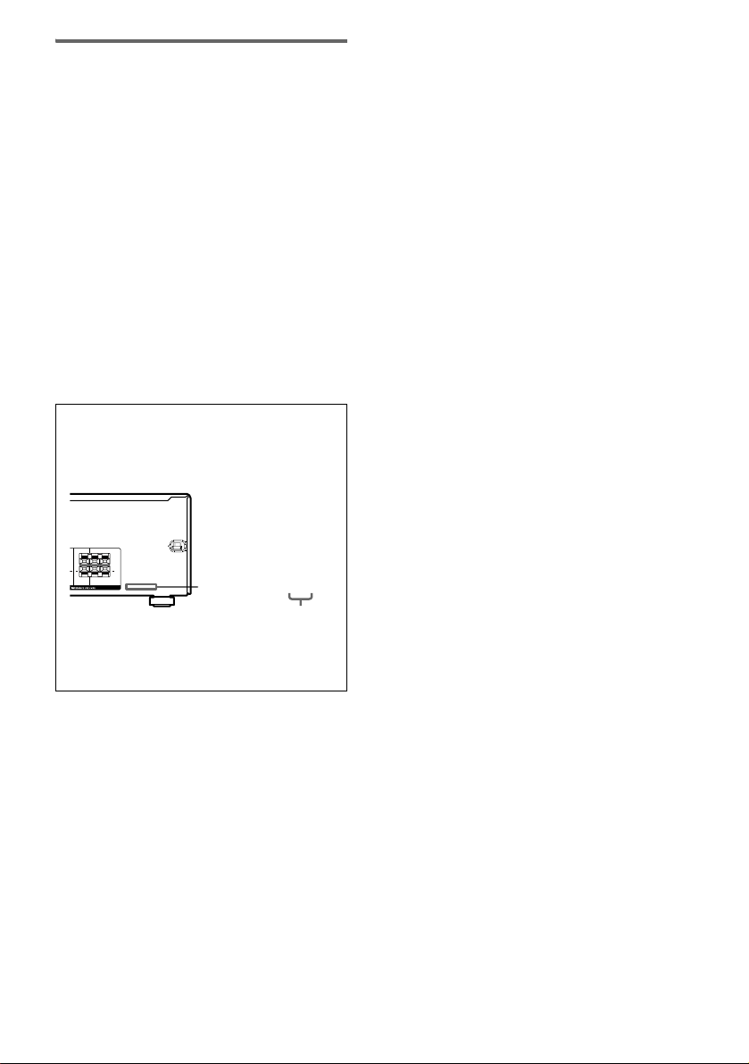
About area codes
The area code of the receiver you purchased is
shown on the lower portion of the rear panel (see
the illustration below).
LR
+
+ +
LR
CENTER FRONT
2-XXX-XXX-XX AA
Area code
Any differences in operation, according to the area
code, are clearly indicated in the text, for example,
“Models of area code AA only”.
This receiver incorporates Dolby* Digital and Pro
Logic Surround and the DTS** Digital Surround
System.
* Manufactured under license from Dolby
Laboratories.
“Dolby”, “Pro Logic” and the double-D symbol are
trademarks of Dolby Laboratories.
** “DTS” and “DTS Digital Surround” are registered
trademarks of Digital Theater Systems, Inc.
US
3

Table of Contents
Getting Started
1: Check how to hookup your
components....................................... 5
1a: Connecting components with
digital audio output jacks ........... 7
1b: Connecting components with
only analog audio jacks .............. 9
2: Connecting the antennas ................... 10
3: Connecting speakers .........................11
4: Connecting the AC power cord ........15
5: Setting up the speakers ..................... 16
6: Adjusting the speaker levels and
balance............................................18
— TEST TONE
Amplifier Operation
Selecting the component .......................19
Listening to FM/AM radio....................20
Presetting radio stations ........................21
Changing the display.............................22
About the indications in the display......23
Enjoying Surround Sound
Using only the front speakers and sub
woofer............................................. 24
— 2CH STEREO
Enjoying higher fidelity sound.............. 24
— AUTO FORMAT DIRECT
Selecting a sound field ..........................25
Advanced Adjustments and
Settings
Switching the audio input mode
for digital components.................... 27
— INPUT MODE
Customizing sound fields ..................... 27
Adjusting the tone................................. 29
Advanced settings................................. 29
Other Operations
Naming preset stations and inputs........ 31
Using the Sleep Timer .......................... 31
Operations Using the Remote
RM-AAU002
Before you use your remote.................. 32
Remote button description.................... 32
Changing the factory setting of an
input button .................................... 35
Additional Information
Precautions ........................................... 36
Troubleshooting.................................... 37
Specifications ....................................... 39
List of button locations and reference
pages............................................... 41
Index ..................................................... 42
US
4

Getting Started
1: Check how to hookup your components
Steps 1a through 1b beginning on page 7 describe how to hook up your components to this receiver.
Before you begin, refer to “Connectable components” below for the pages which describe how to
connect each component.
After hooking up all your components, proceed to “2: Connecting the antennas” (page 10).
Connectable components
Component to be connected Page
DVD player
With digital audio output
With analog audio output only
Satellite tuner
With analog audio output only
Super Audio CD/CD player
With digital audio output
With analog audio output only
VCR 9
a)
Model with a DIGITAL OPTICAL OUTPUT or DIGITAL COAXIAL OUTPUT jack, etc.
b)
Model equipped only with AUDIO OUT L/R jacks, etc.
a)
b)
b)
a)
b)
7
9
9
8
9
Getting Started
continued
US
5

Required cords
The hookup diagrams on the subsequent pages assume the use of the following optional connection
cords (A to C) (not supplied unless indicated).
A Audio cord
White (L)
Red (R)
B Optical digital cord
Notes
• Turn off the power to all components before making any connections.
• Be sure to make connections firmly to avoid hum and noise.
• When connecting an audio cord, be sure to match the color-coded pins to the appropriate jacks on the components:
white (left, audio) to white; and red (right, audio) to red.
• When connecting optical digital cords, insert the cord plugs straight in until they click into place.
• Do not bend or tie optical digital cords.
C Coaxial digital cord (supplied)
Orange
US
6
.
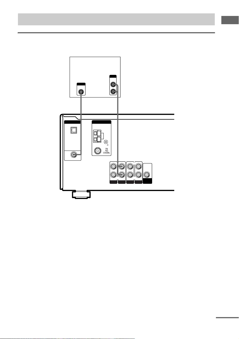
1a: Connecting components with digital audio output jacks
Hooking up a DVD player
For details on the required cords (A–C), see page 6.
DVD player
OUTPUT
AUDIO
OUT
OUTPUT
DIGITAL
COAXIAL
L
R
AC
Getting Started
DIGITAL
OPTICAL
SA-CD/
CD
IN
DVD IN
COAXIAL
ANTENNA
AM
L
R R
AUDIO IN
SA-CD/CD
AUDIO IN
DVD
AUDIO IN
VIDEO 2
L
AUDIO IN
VIDEO 1
AUDIO
OUT
SUB
WOOFER
continued
US
7
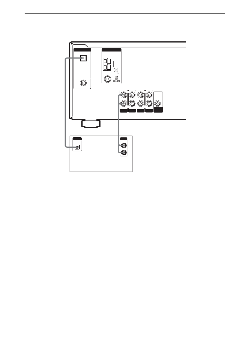
Hooking up a Super Audio CD/CD player
For details on the required cords (A–C), see page 6.
DIGITAL
OPTICAL
SA-CD/
CD
IN
DVD IN
COAXIAL
ANTENNA
AM
L L
R R
AUDIO IN
SA-CD/CD
AUDIO IN
DVD
AUDIO IN
VIDEO 2
AUDIO IN
VIDEO 1
AUDIO
OUT
SUB
WOOFER
BA
DIGITAL
OPTICAL
OUT
Super Audio CD/CD
player
OUTPUT
LINE
L
R
Tip
All the digital audio jacks are compatible with 32 kHz, 44.1 kHz, 48 kHz and 96 kHz sampling frequencies.
Note
The sound is not output when you play a Super Audio CD on the Super Audio CD player connected to the
SA-CD/CD OPTICAL IN jack on this receiver. Connect to the analog input jacks (SA-CD/CD IN jacks). Refer to
the operating instructions supplied with the Super Audio CD player.
US
8
1b: Connecting components with only analog audio jacks
For details on the required cords (A–C), see page 6.
Getting Started
DVD player
OUTPUT
AUDIO
OUT
L
R
DIGITAL
OPTICAL
SA-CD/
CD
IN
DVD IN
COAXIAL
Super Audio CD/CD
Satellite Tuner
or VCR
OUTPUT
AUDIO
OUT
L
A
R
A
ANTENNA
AM
L L
R R
AUDIO IN
SA-CD/CD
AUDIO IN
DVD
AUDIO IN AUDIO IN
VIDEO 2
VIDEO 1
AUDIO
OUT
SUB
WOOFER
AA
player
OUTPUT
LINE
L
R
OUTPUT
AUDIO
OUT
L
R
VCR
US
9
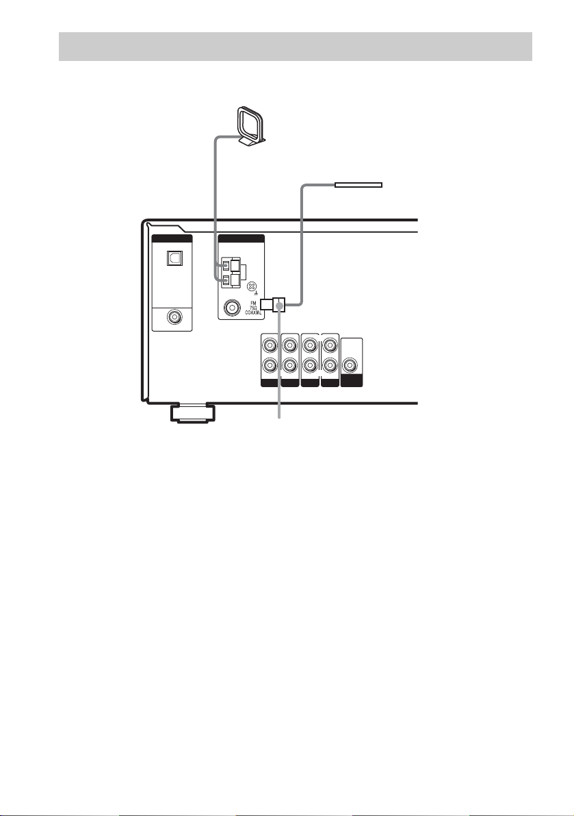
2: Connecting the antennas
Connect the supplied AM loop antenna and FM wire antenna.
AM loop antenna
(supplied)
FM wire antenna
(supplied)
DIGITAL
OPTICAL
SA-CD/
CD
IN
DVD IN
COAXIAL
ANTENNA
AM
L
R
AUDIO IN
SA-CD/CD
AUDIO IN
DVD
AUDIO IN
VIDEO 2
L
R
AUDIO IN
VIDEO 1
AUDIO
OUT
SUB
WOOFER
*
*
The shape of the connector varies depending on the area code.
Notes
• To prevent noise pickup, keep the AM loop antenna away from the receiver and other components.
• Be sure to fully extend the FM wire antenna.
• After connecting the FM wire antenna, keep it as horizontal as possible.
10
US
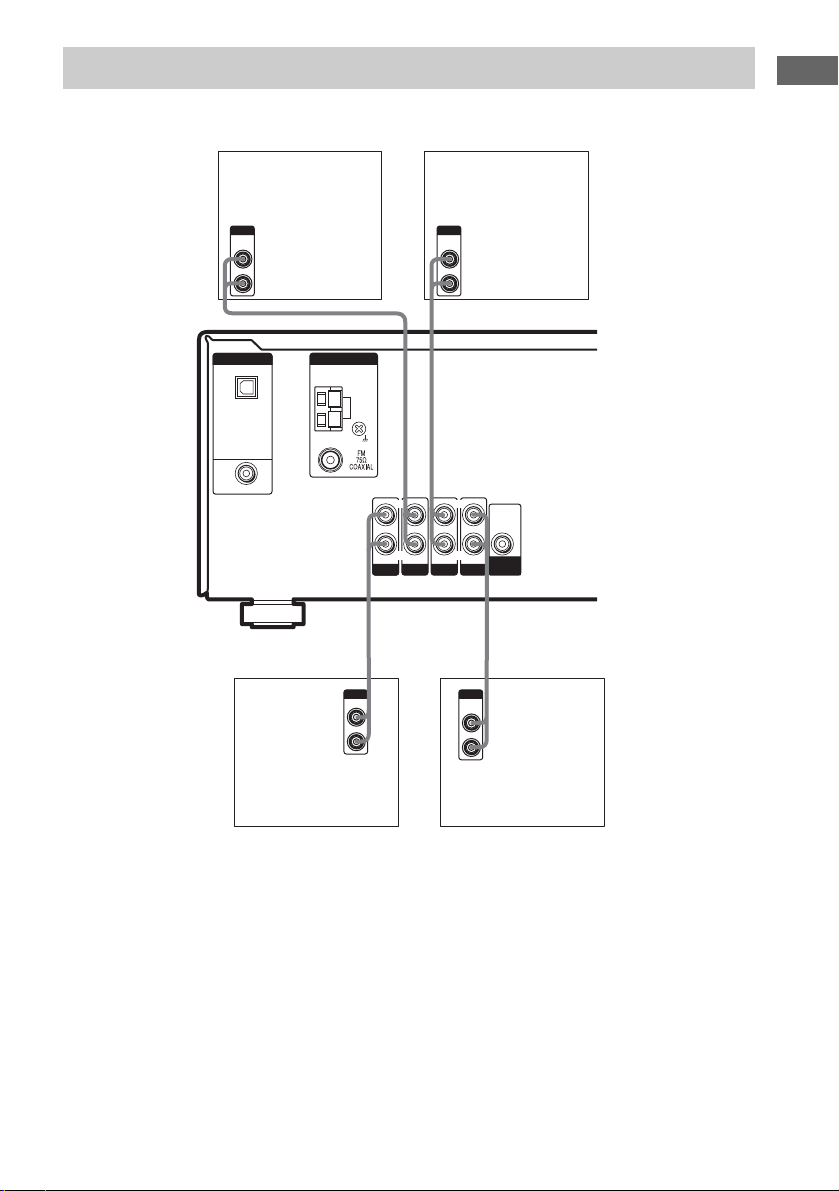
3: Connecting speakers
Connect your speakers to the receiver. This receiver allows you to use a 5.1 channel speaker system.
To fully enjoy theater-like multi channel surround sound requires five speakers (two front speakers, a
center speaker, and two surround speakers) and a sub woofer (5.1 channel).
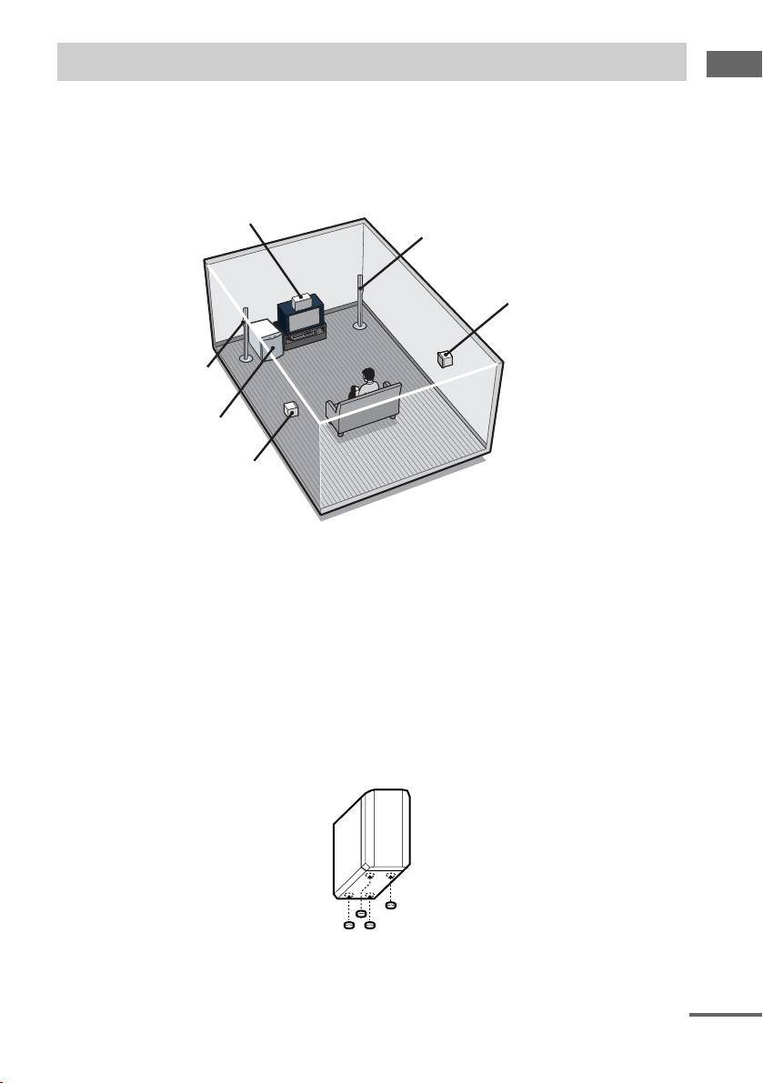
Example of 5.1 channel speaker system configuration
Getting Started
Center speaker
Front speaker (Left)
Sub woofer
Surround speaker (Left)
Tips
• Since the sub woofer does not emit highly directional signals, you can place it wherever you want.
• For greater flexibility in the positioning of the speakers, use the optional WS-FV11 or WS-FV10D floor stand
(available only in certain countries).
• You can also install the surround speakers on the wall (page 14).
Note
Connect the long speaker connecting cords to the surround speaker terminals and the short speaker connecting cords
to the front and center speaker terminals.
Front speaker (Right)
Surround speaker (Right)
Attaching foot pads
To prevent speaker vibration or movement, attach the supplied foot pads to the speaker as shown in the
illustration below (for surround and center speakers only).
Note
Be sure to attach the supplied foot pads to the sub woofer as well.
continued
11
US
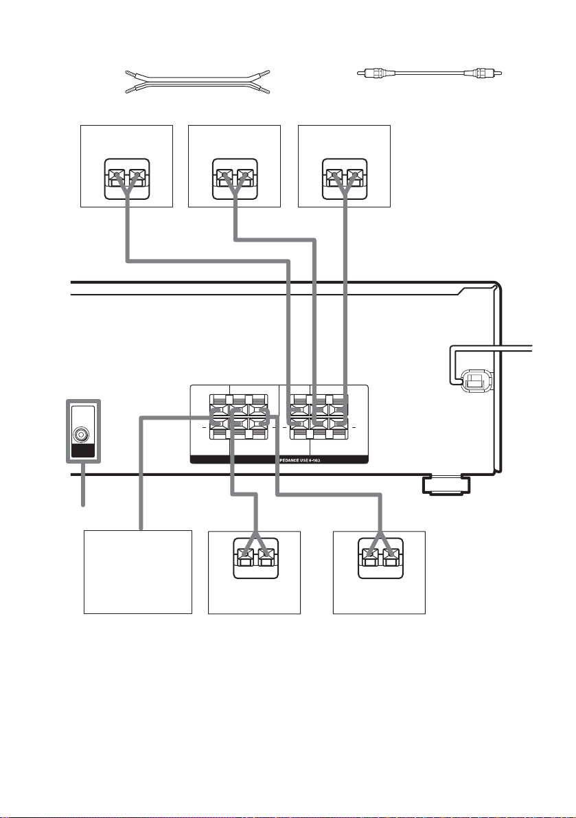
Required cords
A Speaker cords (supplied)
(+)
(–)
B Monaural audio cord (not supplied)
Black
Center speaker
Ee
AUDIO
OUT
SUB
WOOFER
B
*
Front speaker
(Right)
Ee
A
WOOFER
A
LR
+ +
SUB
LR
SURROUND
SPEAKERS
A
Front speaker
(Left)
Ee
LR
+ +
CENTER FRONT
LR
A
A
Sub woofer
E
Surround speaker
(Right)
e
E
Surround speaker
(Left)
* If you have an additional active subwoofer, connect it to SUB WOOFER AUDIO OUT jack.
US
12
e

Attaching the front speakers
base
Before connecting the front speakers, attach it to
the supplied base.
Note
Spread a cloth on the floor to avoid damaging the floor.
1 Remove the front speaker with the
cushion from the carton.
Place TOP cushion and the top portion of
the speaker on the floor as shown below.
BOTTOM
cushion
Top portion
TOP cushion
3 Secure the base to the speaker with the
supplied screws.
Getting Started
4 Connect the speaker cords to the
speaker terminals.
Notes
• Be sure to hold the speaker firmly.
• You can see TOP on the cushion.
2 Remove the BOTTOM cushion from the
speaker. Attach the base on the
speaker properly.
Use the guide on the speaker to align the
hole on the base.
Base
Guide
Guide
Speaker
5 Place the speaker base on the floor and
remove the TOP cushion from the
speaker.
continued
13
US
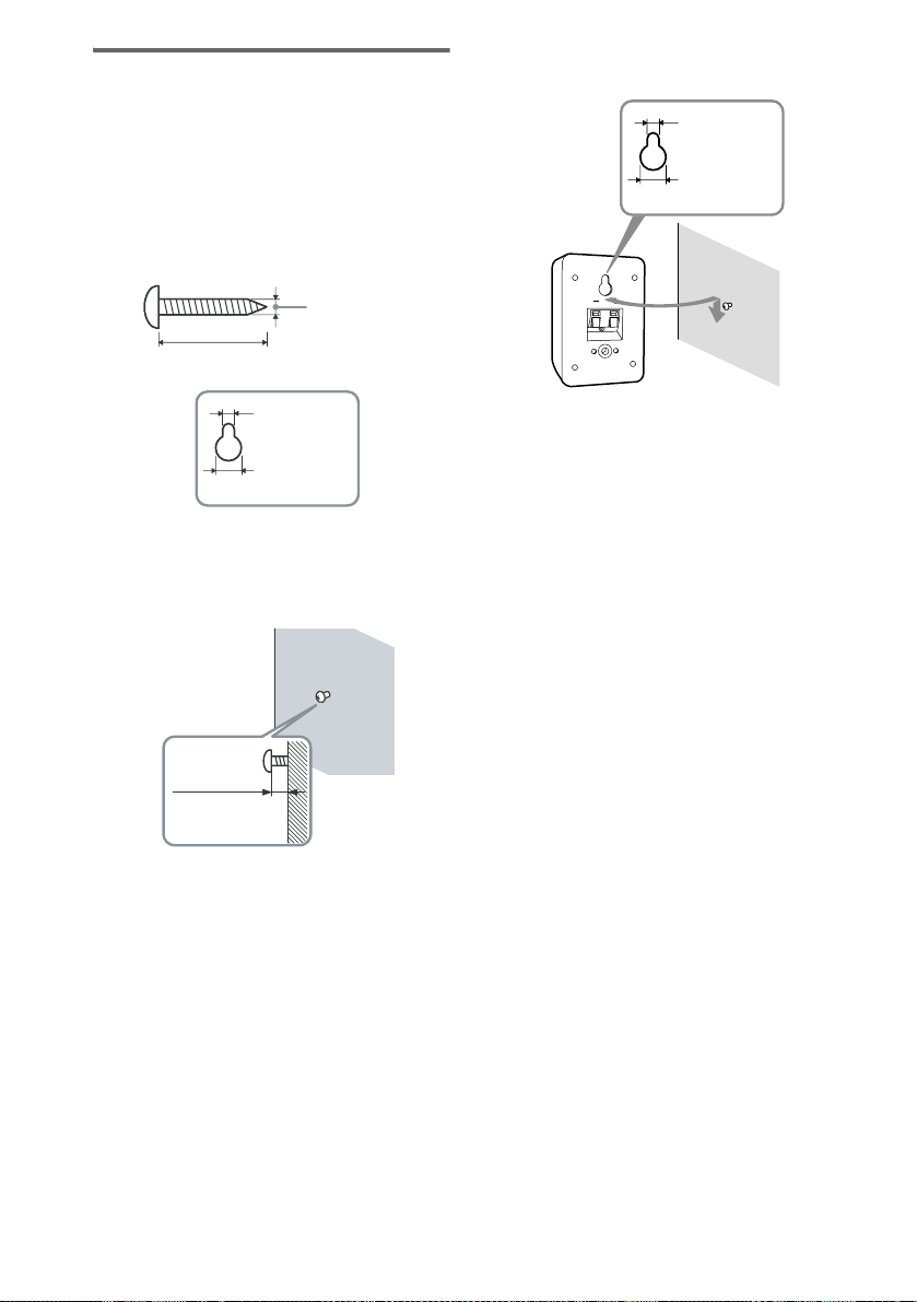
Installing the speakers on the
wall
You can install your surround speakers on the
wall.
1 Prepare screws (not supplied) that are
suitable for the hole on the back of
each speaker. See the illustrations
below.
more than 4 mm
(5/32 inch)
more than 25 mm (1 inch)
3 Hang the speakers on the screws.
Hole on the back of the speaker
4.6 mm
(3/16 inch)
10 mm
(13/32 inch)
4.6 mm
(3/16 inch)
10 mm
(13/32 inch)
Hole on the back of the speaker
2 Fasten the screws to the wall. The
screws should protrude 5 to 7 mm (7/32
to 9/32 inch).
5 to 7 mm
(7/32 to 9/32 inch)
Notes
• Use screws that are suitable for the wall material and
strength. As a plaster board wall is especially fragile,
attach the screws securely to a beam and fasten them
to the wall. Install the speakers on a vertical and flat
wall where reinforcement is applied.
• Contact a screw shop or installer regarding the wall
material or screws to be used.
• Sony is not responsible for accident or damage
caused by improper installation, insufficient wall
strength or improper screw installation, natural
calamity, etc.
14
US
 Loading...