

Sony HT-DDW1500 Operating Instructions Manual

2-662-266-12 (2)
Home Theatre
System
Operating Instructions
HT-DDW1500
©2006 Sony Corporation
WARNING
To reduce the risk of fire or electric
shock, do not expose this apparatus to
rain or moisture.
To prevent fire, do not cover the ventilation of the
apparatus with newspapers, table-cloths, curtains,
etc. And don’t place lighted candles on the
apparatus.
To prevent fire or shock hazard, do not place objects
filled with liquids, such as vases, on the apparatus.
Do not install the appliance in a confined space,
such as a bookcase or built-in cabinet.
Don’t throw away batteries with
general house waste; dispose of
them correctly as chemical waste.
GB
2
About This Manual
• The instructions in this manual are for model
HT-DDW1500. In this manual, models of area
code SP is used for illustration purposes unless
stated otherwise. Any difference in operation is
clearly indicated in the text, for example, “Models
of area code CEL only”.
• The instructions in this manual describe the
controls on the supplied remote. You can also use
the controls on the receiver if they have the same
or similar names as those on the remote.
The HT-DDW1500 consists of:
• Receiver STR-K1500
• Speaker system
– Front speakers SS-MFP15
– Center speaker SS-CNP15
– Surround/Surround SS-SRP15
back speakers
– Sub woofer SA-WP1500
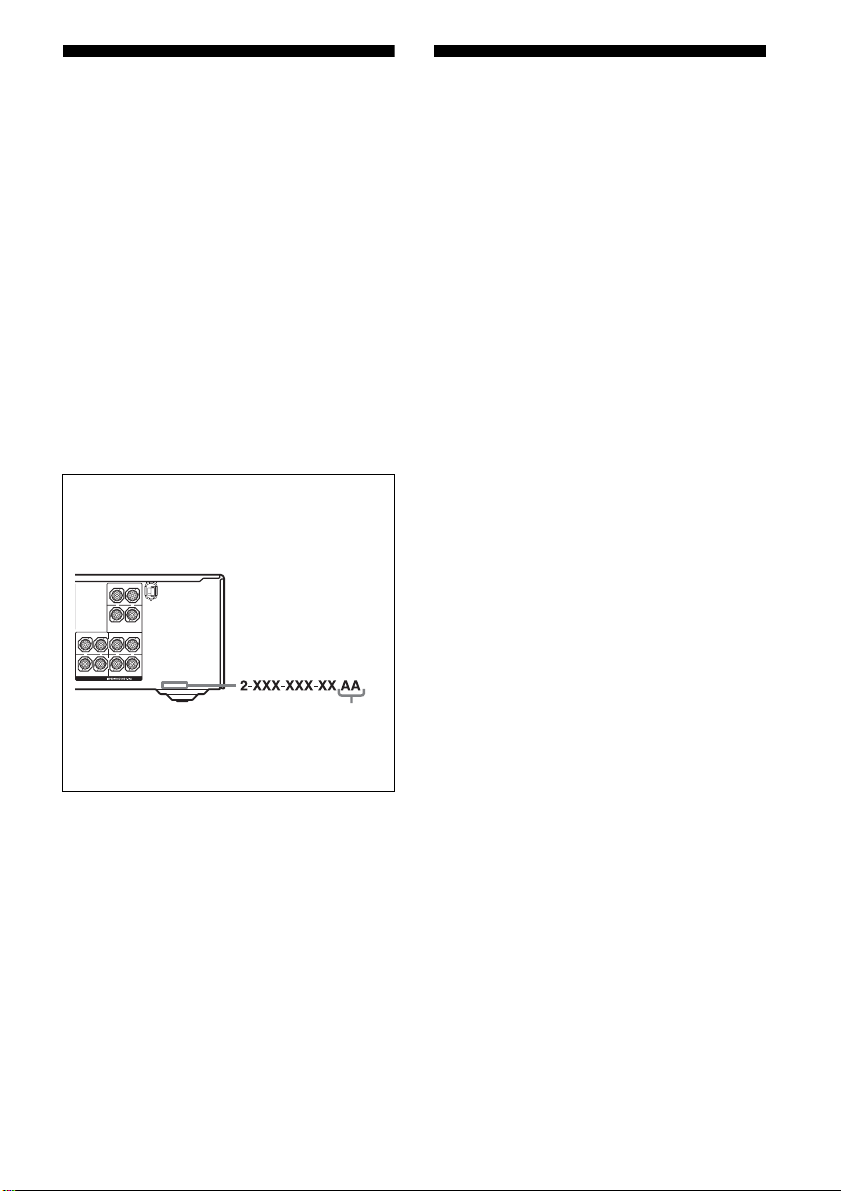
About area codes
The area code of the receiver you purchased is
shown on the lower right portion of the rear panel
(see the illustration below).
CENTER
+
–
SURROUND BACK
L
L
+–+
–
R
R
SURROUND FRONT
SPEAKERS
Note for the supplied remote
(RM-AAP013)
The AUX and 12 buttons on the remote are not
available for receiver operation.
Area code
Any differences in operation, according to the area
code, are clearly indicated in the text, for example,
“Models of area code AA only”.
This receiver incorporates Dolby* Digital and Pro
Logic Surround and the DTS** Digital Surround
System.
* Manufactured under license from Dolby
Laboratories.
“Dolby”, “Pro Logic”, “Surround EX”, and the
double-D symbol are trademarks of Dolby
Laboratories.
** “DTS”, “DTS-ES”, “Neo:6”, and “DTS 96/24”
are trademarks of Digital Theater Systems, Inc.
This receiver incorporates High-Definition
Multimedia Interface (HDMI
TM
) technology.
HDMI, the HDMI logo and High-Definition
Multimedia Interface are trademarks or registered
trademarks of HDMI Licensing LLC.
GB
3

Table of Contents
Getting Started
Description and location of parts...................5
1: Installing speakers ................................... 14
2: Connecting speakers................................16
3a: Connecting the audio components.........18
3b: Connecting the video components ........21
3c: Connecting the lighting device ..............28
4: Connecting the antennas..........................29
5: Preparing the receiver and the remote .....30
6: Selecting the speaker ...............................32
7: Calibrating the appropriate settings
automatically
(AUTO CALIBRATION).......................32
8: Adjusting the speaker levels and balance
(TEST TONE) ........................................35
Playback
Selecting a component.................................36
Listening/Watching a component ................38
Amplifier Operations
Navigating through menus...........................40
Adjusting the level (LEVEL menu)............. 44
Adjusting the tone (TONE menu) ...............45
Settings for the surround sound
(SUR menu)............................................45
Settings for the tuner (TUNER menu).........47
Settings for the audio (AUDIO menu).........47
Settings for the video (VIDEO menu).........48
Settings for the system (SYSTEM menu) ...49
Calibrating the appropriate settings
automatically (A. CAL menu) ................51
Enjoying Surround Sound
Enjoying Dolby Digital and DTS Surround
sound (AUTO FORMAT DIRECT)....... 52
Selecting a pre-programmed sound field.... 54
Using only the front speakers and sub woofers
(2CH STEREO) ..................................... 57
Resetting sound fields to the initial settings 57
Tuner Operations
Listening to FM/AM radio.......................... 58
Presetting radio stations .............................. 59
Other Operations
Switching the audio input mode
(INPUT MODE) .................................... 62
Watching component images from other
inputs
(COMPONENT VIDEO ASSIGN) ....... 62
Watching HDMI image from other inputs
(HDMI ASSIGN)................................... 63
(Except for models of area code MX, E51,
AR)
Naming inputs............................................. 64
Changing the display .................................. 65
Using the Sleep Timer ................................ 65
Recording using the receiver....................... 66
Using the Remote
Programming the remote ............................ 67
Additional Information
Glossary ...................................................... 70
Precautions.................................................. 72
Troubleshooting .......................................... 73
Specifications.............................................. 77
Index ............................................. Back cover
GB
4
Getting Started
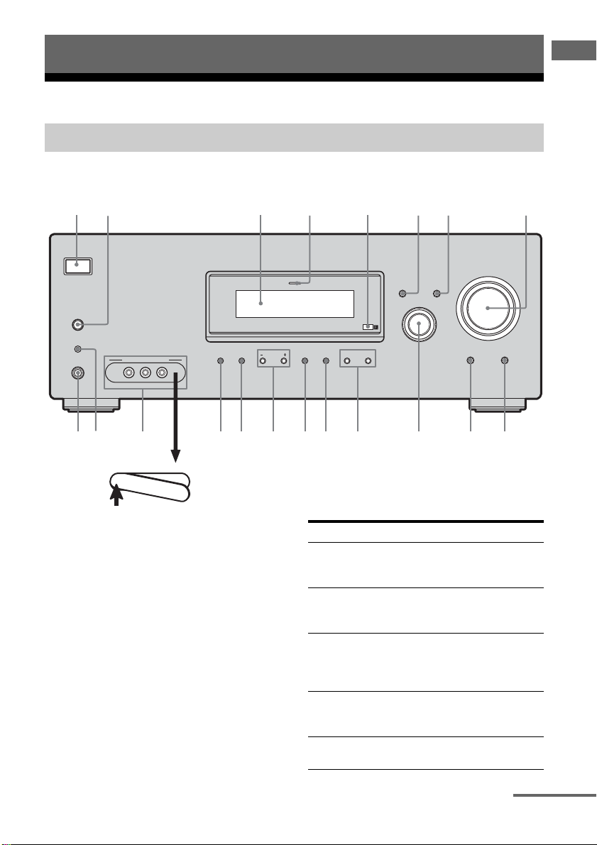
Description and location of parts
Receiver
Front panel
1 3246 875
Getting Started
?/1
SPEAKERS
(ON/OFF)
AUTO CAL MIC
PHONES
VIDEO 3 IN/PORTABLE AV IN
VIDEO L AUDIO R
MEMORY/
TUNING
ENTER
MODE TUNING 2CH A.F.D. MOVIE MUSIC
w; qaqsqkql qdqfqgqhqj
PUSH
To remove the cover
Press PUSH.
When you remove the cover, keep it out of
reach from children.
MULTI CHANNEL DECODING
DISPLAY
INPUT MODE
INPUT SELECTOR
Name Function
A ?/1 Press to turn the receiver
B SPEAKERS
(ON/OFF)
C Display The current status of the
D MULTI CHANNEL
DECODING lamp
E Remote sensor Receives signals from
on or off (page 31, 38, 39,
57, 78).
Press to turn the speakers
and sub woofers on or off
(page 32).
selected component or a
list of selectable items
appears here (page 7).
Lights up when multi
channel audio is decoded
(page 39).
remote commander.
MASTER VOLUME
MULTI CH IN MUTING
9q;
continued
GB
5

Name Function
F DISPLAY Press to select information
G INPUT MODE Press to select the input
H MASTER
VOLUME
I MUTING Press to mute the sound
J MULTI CH IN Press to select the audio
K INPUT
SELECTOR
L MOVIE,
MUSIC
M A.F.D. Press to select A.F.D.
N 2CH Press to select 2CH
O TUNING +/– Press to scan a station
P TUNING MODE Press to select the tuning
Q MEMORY/ENTER Press to store a station or
displayed on the display
(page 65).
mode when the same
components are connected
to both digital and analog
jacks (page 62).
Turn to adjust the volume
level of all speakers at the
same time (page 36, 37,
38, 39).
(page 37).
directly from the
components connected to
the MULTI CH IN jacks
(page 36).
Turn to select the input
source to playback (page
36, 38, 39, 58, 59 60, 61,
62, 64, 66).
Press to select sound fields
(MOVIE, MUSIC) (page
54).
mode (page 52).
STEREO mode (page 56,
57).
(page 58, 60).
mode (page 58, 60, 78 ).
enter the selection when
selecting the settings
(page 31).
Name Function
R VIDEO 3 IN/
PORTABLE AV IN
jacks
S AUTO CAL MIC
jack
T PHONES jack Connects to a headphone
To connect a camcorder or
video game (page 27, 37).
Connects to the supplied
ECM-AC2 optimizer
microphone for the Auto
Calibration function (page
32).
(page 55).
GB
6
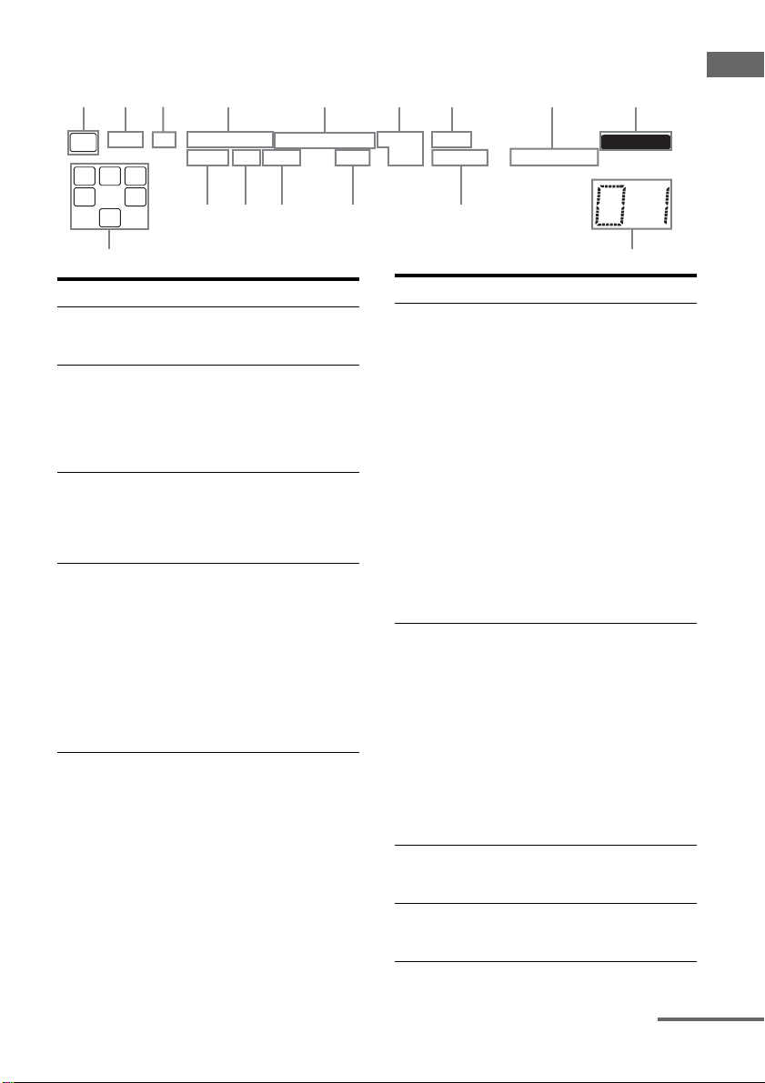
About the indicators on the display
2143567 8 9
SP
DIGITAL EX
LFE
SW
L C R
SL S SR
SB
;
SLEEP OPT COAX 96/24
qg
;
PRO LOGIC IIx
qdqf
HDMI
qs
DTS-ES
NEO:6
qa
Getting Started
MEMORY
STEREO MONOD.RANGE
qh
Name Function
A SW Lights up when the audio signal
B LFE Lights up when the disc being
C SP Lights up according to the
D ;DIGITAL
(EX)
is output from the SUB
WOOFER jack.
played back contains an LFE
(Low Frequency Effect)
channel and the LFE channel
signal is actually being
reproduced.
speaker used. However, this
indicator do not light up if the
speaker output is turned off or if
a headphone is connected.
Lights up when Dolby Digital
signals are input. “;
DIGITAL EX” lights up when
Dolby Digital Surround EX
signals are decoded.
Note
When playing a Dolby Digital
format disc, be sure that you
have made digital connections
and that INPUT MODE is not
set to “ANALOG” (page 62).
Name Function
E ;PRO
LOGIC (II)/
(IIx)
F DTS (-ES)/
(96/24)
G NEO:6 Lights up when DTS Neo:6
H Tu ner
indicators
“; PRO LOGIC” lights up
when the receiver applies Pro
Logic processing to 2 channel
signals in order to output the
center and surround channel
signals. “; PRO LOGIC II”
lights up when the Pro Logic II
Movie/Music/Game decoder is
activated.
“; PRO LOGIC IIx” lights up
when the Pro Logic IIx Movie/
Music/Game decoder is
activated.
Note
Dolby Pro Logic IIx decoding
does not function for DTS
format signals or for signals
with a sampling frequency of
more than 48 kHz.
“DTS” lights up when DTS
signals are input. “DTS-ES”
lights up when DTS-ES signals
are input.
“DTS 96/24” lights up when the
receiver is decoding DTS 96
kHz/24 bit signals.
Note
When playing a DTS format
disc, be sure that you have made
digital connections and that
INPUT MODE is not set to
“ANALOG” (page 62).
Cinema/Music decoder is
activated (page 53).
Lights up when using the
receiver to tune in radio stations
(page 58), etc.
q;
continued
GB
7
Name Function
I MEMORY Lights up when a memory
J Preset
station
indicators
K D.RANGE Lights up when dynamic range
L HDMI* Flashes when you select
M COAX Lights up when INPUT MODE
N OPT Lights up when INPUT MODE
O SLEEP Lights up when the Sleep Timer
function, such as Preset
Memory (page 59), etc., is
activated.
Lights up when using the
receiver to tune in radio stations
you have preset. For details on
presetting radio stations, see
page 59.
compression is activated (page
41).
“HDMI A.” in the VIDEO
menu (page 25).
is set to “AUTO” and the source
signal is a digital signal being
input through the COAXIAL
jack, or when INPUT MODE is
set to “COAX IN” (page 62).
is set to “AUTO” and the source
signal is a digital signal being
input through the OPTICAL
jack, or when INPUT MODE is
set to “OPT IN” (page 62).
function is activated (page 65).
Name Function
P Playback
channel
indicators
L
R
C
SL
SR
S
SB
* Except for models of area code MX, E51, AR.
The letters (L, C, R, etc.)
indicate the channels being
played back. The boxes around
the letters vary to show how the
receiver downmixes the source
sound.
Front Left
Front Right
Center (monaural)
Surround Left
Surround Right
Surround (monaural or the
surround components obtained
by Pro Logic processing)
Surround back (the surround
back components obtained by
6.1 channel decoding)
Example:
Recording format (Front/
Surround): 3/2.1
Sound Field: A.F.D. AUTO
SW
L C R
SL SR
GB
8
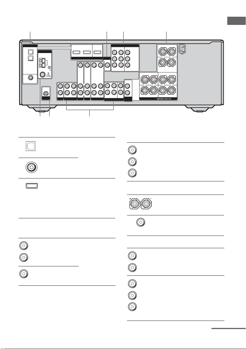
Rear panel
1 2 3 4
57 6
DIGITAL
OPTICAL
VIDEO 1
ANTENNA
IN
VIDEO 2
IN
DVD
IN
COAXIAL
D-LIGHT
SYNC OUT
Getting Started
DVD IN
VIDEO 2 IN
MONITOR OUT
ASSIGNABLE
L
R
IN
HDMI
VIDEO IN VIDEO IN
L
R
AUDIO IN
AUDIO IN
DVD
VIDEO 2
VIDEO OUT
AUDIO OUT
VIDEO 1
L
R
AM
L
R
IN
OUT
SA-CD/CD
MD/TAPE
VIDEO IN
AUDIO IN
MONITOR
VIDEO OUT
FRONT
MULTI CH IN
COMPONENT VIDEO
ASSIGNABLE
DVDINVIDEO 2INMONITOR
L
CENTER
R
SUB
SURROUND
WOOFER
OUT
AUDIO
OUT
SUB
WOOFER
Y
PB/C
B
/B–Y
P
R/CR
/R–Y
CENTER
+
SURROUND BACK
L
+
–
+
R
SURROUND FRONT
SPEAKERS
R
–
L
–
A DIGITAL INPUT/OUTPUT section
OPTICAL
IN jack
COAXIAL IN
jack
HDMI IN/
MONITOR
OUT jack
Connects to a DVD
player, etc. The
COAXIAL jack
provides a better
quality of loud
sound (page 23,
26).
Connects to a DVD
player, or a satellite
a)b)
tuner. The image
C COMPONENT VIDEO INPUT/
OUTPUT section
Green
Blue
Red
D SPEAKER section
and the sound are
output to a TV or a
projector (page
25).
B VIDEO/AUDIO INPUT/OUTPUT
section
White (L)
Red (R)
Yellow
AUDIO IN/
OUT jack
VIDEO IN/
OUT jack
Connects the video
and audio jacks of
a VCR or a DVD
player (page 22,
23, 24, 26, 27).
a)
E AUDIO INPUT/OUTPUT section
White (L)
Red (R)
White (L)
Red (R)
Black
COMPONENT
VIDEO
INPUT/
OUTPUT
a)
jack
AUDIO IN/
OUT jack
MULTI
CHANNEL
INPUT jack
Connects to a DVD
player, TV, or a
satellite tuner. You
can enjoy high
quality image
(page 22, 24, 26).
Connects to the
speakers (page 16).
Connects to the
sub woofers (page
16).
Connects to an MD
deck or CD player,
etc. (page 20).
Connects to a
Super Audio CD
player or DVD
player which has
an analog audio
jack for 5.1
channel sound
(page 19).
continued
GB
9
F D-LIGHT SYNC OUT section
D-LIGHT
SYNC OUT
jack
Connects to a
lighting device
(page 28).
G ANTENNA section
FM
ANTENNA
AM
ANTENNA
a)
You can watch the selected input image when you
connect the MONITOR OUT jack to a TV monitor
(page 22).
b)
Except for models of area code MX, E51, AR.
Connects to the
FM wire antenna
supplied with this
receiver (page 29).
Connects to the
AM loop antenna
supplied with this
receiver (page 29).
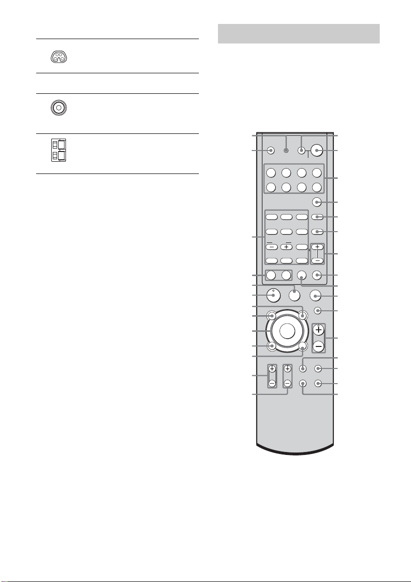
Remote commander
You can use the supplied remote RM-AAP013
to operate the receiver and to control the Sony
audio/video components that the remote is
assigned to operate. You can also program the
remote to control non-Sony audio/video
components. For details, see “Programming
the remote” (page 67).
AV ?/1
(on/standby)
wl
wk
TV ?/1
(on/standby)
switch
wj
wh
wg
wf
wd
ws
wa
w;
ql
qk
qj
TV ?/1 AV ?/1
VIDEO1 VIDEO2
MD/TAPE SA-CD/CD TUNER
TOP MENU/
DISPLAY
P
RM SET UP
SYSTEM STANDBY
VIDEO3 DVD
2CH
A.F.D.
123
456
AUDIO
ANGLE
TUNING
789
SUBTITLEMEMORY ENTER
>
.
>10/11 12
0/10
D.TUNING DISC ALT
M
m
ANT
CLEAR
SEARCH MODE
X
H
AV MENU
GUIDE
F
G
f
RETURN/EXIT
TV VOL TV CH
MOVIE
DUAL
MONO
JUMP/
TIME
-
g
VIDEO
WIDE
O
TV/
?/1
SLEEP
AUX
MULTI CH
MUSIC
FM
MODE
PRESET/
CH/D.SKIP
x
MUTING
MASTER
VOL
AMP
MENU
AUTO
CAL
1
switch
?/1
2
(on/standby)
switch
3
4
5
6
7
8
9
0
qa
qs
qd
qf
qg
qh
10
GB

Name Function
A AV ?/1 Press to turn on or off the
B ?/1 Press to turn the receiver on or
SLEEP Press ALT (H) and then press
C Input buttons Press one of the buttons to
audio/video components that
the remote is programmed to
operate.
If you press ?/1 (B) at the
same time, it will turn off the
receiver and other
components (SYSTEM
STANDBY).
Note
The function of the AV ?/1
switch changes automatically
each time you press the input
buttons (C).
off.
To turn off all components,
press ?/1 and AV ?/1 (A) at
the same time (SYSTEM
STANDBY).
SLEEP to activate the Sleep
Timer function and the
duration which the receiver
turns off automatically.
select the component you
want to use. When you press
any of the input buttons, the
receiver turns on. The buttons
are factory assigned to control
Sony components as follows.
You can program the remote
to control non-Sony
components following the
steps in “Programming the
remote” on page 67.
Button Assigned Sony
VIDEO1 VCR (VTR mode 3)
VIDEO2 VCR (VTR mode 1)
VIDEO3 VCR (VTR mode 2)
DVD DVD player
MD/TAPE MD deck
SA-CD/CD Super Audio CD/CD
TUNER Built-in tuner
AUX* Not assigned
* The AUX button is not available
for receiver operation.
component
player
Name Function
D MULTI CH Press to select the audio
E MUSIC Press to select sound fields
F FM MODE Press to select FM monaural
G PRESET/
CH/D.SKIP
+/–
H ALT Press to light up the button. It
I -/-- Press to select the channel
DISC Press to select a disc directly
SEARCH
MODE
J x Press to stop playback of the
K MUTING Press to mute the sound.
L MASTER
VOL +
a)
M TV/VIDEO Press to select the input signal
directly from the components
connected to the MULTI CH
IN jacks.
(MUSIC).
or stereo reception.
Press to
– select preset stations.
– select preset channels of the
TV, VCR, satellite tuner,
Blu-ray disc recorder, or
hard disc recorder.
– skip disc of the CD player,
VCD player, DVD player,
MD deck, or LD player
(multi-disc changer only).
changes the remote key
function to activate the
buttons with orange printing.
entry mode, either one or two
digit of the TV, Blu-ray disc
recorder, hard disc recorder,
PSX, or satellite tuner.
of the CD player or VCD
player (multi-disc change
only).
Press to select the searching
mode or unit for search (track,
index, etc.) of the DVD
player.
VCR, CD player, VCD player,
LD player, DVD player, MD
deck, DAT deck, tape deck,
Blu-ray disc recorder, hard
disc recorder, or PSX.
Press to adjust the volume
/–
level of all speakers at the
same time.
(TV input or video input).
continued
11
Getting Started
GB

Name Function
N AMP MENU Press to display the menu of
O AUTO CAL Press to activate the Auto
P WIDE Press ALT (H) and then press
Q TV CH +
R TV VOL
a)
/–
+
S RETURN/
EXIT O
T DISPLAY Press to select information
U Control
buttons
V TOP MENU/
GUIDE
the receiver. Then, use the
control buttons to perform
menu operations.
Calibration function.
WIDE to select the wide
picture mode.
a)
/– Press to select preset TV
channels.
Press to adjust the TV volume
level.
Press to
– return to the previous menu.
– exit the menu while the
menu or on-screen guide of
the VCD player, LD player,
DVD player, Blu-ray disc
recorder, hard disc recorder,
PSX, or satellite tuner is
displayed on the TV screen.
displayed on the TV screen of
the TV, VCR, VCD player,
LD player, DVD player, CD
player, MD deck, Blu-ray disc
recorder, hard disc recorder,
PSX, or satellite tuner.
After pressing AMP MENU
(N), TOP MENU/GUIDE
(V), or AV MENU (W),
press the control button V, v,
B or b to select the settings.
When you press TOP MENU/
GUIDE or AV MENU, press
the control button to enter the
selection.
Press to display
– DVD title.
– menu or on-screen guide of
the satellite tuner, Blu-ray
disc recorder, hard disc
recorder, or PSX on the TV
screen.
Then, use the control buttons
to perform menu operations.
Name Function
W AV M E N U Press to display the menus of
a)
X H
Y X Press to pause playback or
Z m/M Press to
D. TUNING Press to enter direct tuning
ANT Press ALT (H) and then press
CLEAR Press ALT (H) and then press
the VCR, DVD player,
satellite tuner, Blu-ray disc
recorder, hard disc recorder,
or PSX on the TV screen.
Then, use the control buttons
to perform menu operations.
Press to start playback of the
VCR, CD player, VCD player,
LD player, DVD player, MD
deck, DAT deck, tape deck,
Blu-ray disc recorder, hard
disc recorder, or PSX.
recording of the VCR, CD
player, VCD player, LD
player, DVD player, MD
deck, DAT deck, tape deck,
Blu-ray disc recorder, hard
disc recorder, or PSX. (Also
starts recording with
components in recording
standby.)
– search tracks in the forward/
backward direction of the
CD player, VCD player, LD
player, DVD player, MD
deck, Blu-ray disc recorder,
hard disc recorder, or PSX.
– fastforward/rewind of the
VCR, DAT deck, or tape
deck.
mode.
ANT to select the signal
output from the antenna
terminal of the VCR or
satellite tuner (TV signal or
video signal).
CLEAR to
– clear a mistake when you
press the incorrect numeric
button.
– return to continuous
playback, etc. of the CD
player, DVD player, Blu-ray
disc recorder, PSX, or
satellite tuner.
12
GB

Name Function Name Function
wj TUNING +/– Press to scan a station.
./> Press to skip tracks of the
VCR, CD player, VCD player,
LD player, DVD player, MD
deck, DAT deck, tape deck,
Blu-ray disc recorder, hard
disc recorder, or PSX.
2CH Press to select 2CH STEREO
mode.
A.F.D. Press to select A.F.D. mode.
MOVIE Press to select sound fields
(MOVIE).
DUAL MONO Press to select the language
you want during digital
broadcast.
AUDIO Press to change the sound to
Multiplex, Bilingual or Multi
channel TV sound of the TV,
VCR, DVD player, satellite
tuner, Blu-ray disc recorder,
hard disc recorder, or PSX.
ANGLE Press to select the viewing
angle or change the angles of
the DVD player or Blu-ray
disc recorder.
JUMP/TIME Press to
– toggle between the previous
and the current channels of
the satellite tuner, TV, or
Blu-ray disc recorder.
– show the time or display the
playing time of a disc, etc. of
the CD player, MD deck,
VCD player, or DVD player.
MEMORY Press to store a station.
SUBTITLE Press ALT (H) and then press
SUBTITLE to change the
subtitles of the DVD player.
ENTER Press ALT (H) and then press
ENTER to enter the value
after selecting a channel, disc
or track using the numeric
buttons.
wj Numeric
buttons
Press ALT (H) and then press
the numeric buttons to
– preset/tune to preset
stations.
– select track numbers of the
CD player, VCD player, LD
player, DVD player, MD
deck, DAT deck, or tape
deck. Press 0/10 to select
track number 10.
– select channel numbers of
the TV, VCR, satellite tuner,
Blu-ray disc recorder, hard
disc recorder, or PSX.
>10/11 Press ALT (H) and then press
>10/11 to select track
numbers over 10 of the VCR,
CD player, VCD player, LD
player, MD deck, tape deck,
Blu-ray disc recorder, hard
disc recorder, satellite tuner,
TV, or PSX.
wk TV ?/1 Press to turn the TV on or off.
wl RM SET UP Press to set up the remote.
a)
The MASTER VOL +, TV VOL +, TV CH +, and
H buttons have tactile dots. Use the tactile dots
as references when operating the receiver.
Notes
• The AUX and 12 buttons on the remote are not
available for receiver operation.
• Some functions explained in this section may not
work depending on the model.
• The above explanation is intended to serve as an
example only. Therefore, depending on the
component, the above operation may not be
possible or may operate differently than described.
Getting Started
13
GB
1: Installing speakers
This receiver allows you to use a 6 channel
speaker with 2 sub woofer system.
To fully enjoy theater-like multi channel
surround sound requires five speakers (two
front speakers, a center speaker, and two
surround speakers) and a sub woofer (5.1
channel).
You can enjoy high fidelity reproduction of
DVD software recorded sound in the Surround
EX format if you connect one additional
surround back speaker (6.1 channel) (see
“Using the surround back decoding mode
(SUR BACK DECODING)”) on page 46.
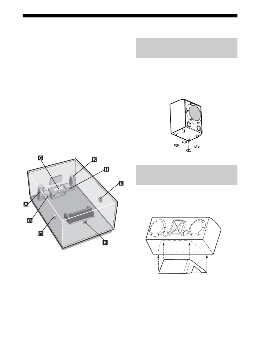
Example of 6 channel speaker
with 2 sub woofer system
configuration
Installing the speakers on a flat
surface
Before you install the center speaker, surround
speakers, surround back speaker and sub
woofers, be sure to attach the supplied foot
pads to prevent vibration or movement as
shown in the illustration below.
Installing the center speaker on
the speaker stand
For greater flexibility in positioning the center
speaker, use the supplied speaker stand to
place the center speaker as shown in the
illustration below.
AFront speaker (L)
BFront speaker (R)
CCenter speaker
DSurround speaker (L)
ESurround speaker (R)
FSurround back speaker
GSub woofer
HSub woofer
Tip
Since the sub woofer does not emit highly
directional signals, you can place it wherever you
want.
GB
14
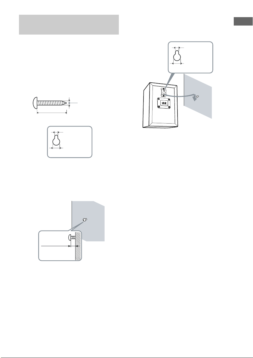
Installing the speakers on the
wall
You can install your surround and surround
back speakers on the wall.
3 Hang the speakers on the
screws.
Metal hook on the back of the speaker
4.6 mm
Getting Started
1 Prepare screws (not supplied)
that are suitable for the metal
hook on the back of each
speaker as shown in the
illustrations below.
more than 4 mm
more than 25 mm
4.6 mm
10 mm
Metal hook on the back of the speaker
2 Fasten the screws to the wall.
The screws should protrude 5
to 7 mm.
10 mm
–
+
Notes
• Use screws that are suitable for the wall material
and strength. As a plaster board wall is especially
fragile, attach the screws securely to a beam and
fasten them to the wall. Install the speakers on a
vertical and flat wall where reinforcement is
applied.
• Contact a screw shop or installer regarding the wall
material or screws to be used.
• Sony is not responsible for accident or damage
caused by improper installation, insufficient wall
strength or improper screw installation, natural
calamity, etc.
5 to 7 mm
15
GB
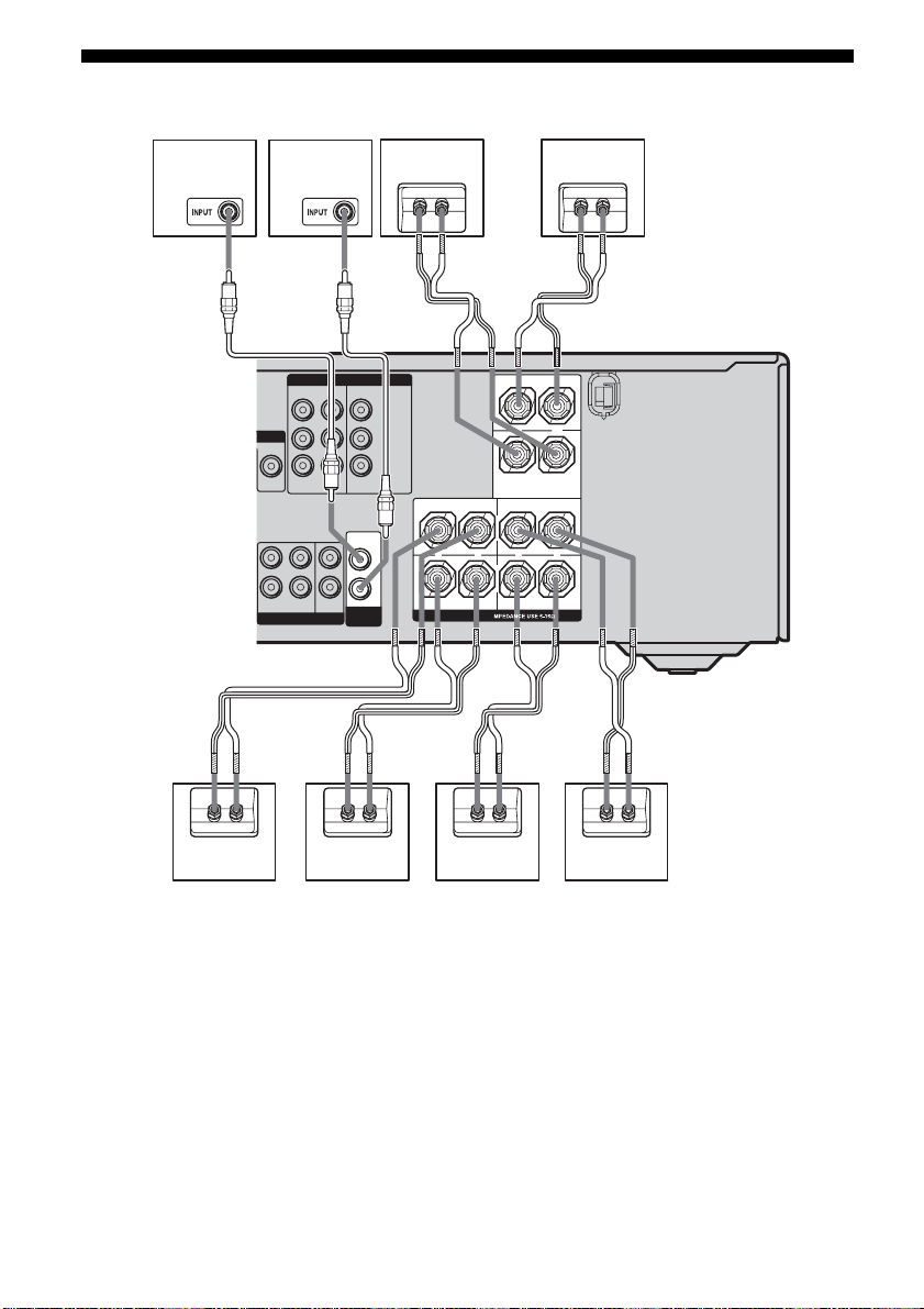
2: Connecting speakers
H
AC
C
GF
A
COMPONENT VIDEO
ONITOR
VIDEO OUT
FRONT
MULTI CH IN
L
R
ASSIGNABLE
DVDINVIDEO 2INMONITOR
SURROUND
CENTER
SUB
WOOFER
OUT
AUDIO
OUT
SUB
WOOFER
Y
PB/C
B
/B–Y
P
R/CR
/R–Y
C
L
+
R
SURROUND
SPEAKERS
B
B
SURROUND BACK
–
CENTER
+
+
FRONT
–
L
–
R
C
+–+–
B
A Monaural audio cord (supplied)
B Speaker cord (short) (supplied)
C Speaker cord (long) (supplied)
AFront speaker (L)
BFront speaker (R)
CCenter speaker
DSurround speaker (L)
ESurround speaker (R)
FSurround back speaker
GSub woofer
HSub woofer
GB
16
+–
+– +–+–
BAED
Tip
Use the supplied speakers to optimize the system’s
performance.

To connect the speaker
correctly
Check the speaker type by referring to the
speaker label* on the speakers.
Character
on speaker
label
L Front left Rear panel
R Front right Rear panel
SL Surround left Rear panel
SR Surround right Rear panel
SB Surround back Rear panel
* The center speaker and sub woofer do not have any
character on the speaker label. For details on the
speaker type, see page 3.
Speaker type Location of
speaker label
Getting Started
17
GB
3a: Connecting the audio components
How to hook up your
components
This section describes how to hook up your
components to this receiver. Before you begin,
refer to “Component to be connected” below
for the pages which describe how to connect
each component.
After hooking up all your components,
proceed to “4: Connecting the antennas” (page
29).
Component to be connected
Component With Page
Super Audio
CD player/CD
player
MD deck/Tape
deck
a)
Model with MULTI CH OUTPUT jacks, etc. This
Multi-channel audio
a)
output
Analog audio output
b)
only
Analog audio output
b)
only
connection is used to output audio decoded by the
component’s internal multi-channel decoder
through this receiver.
b)
Model equipped only with AUDIO OUT L/R
jacks, etc.
19
20
20
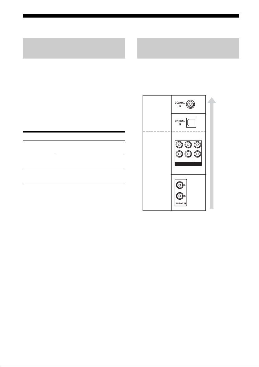
Audio input/output jack to be
connected
The sound quality depends on the connecting
jack. Refer to the illustration that follows.
Select the connection according to the jacks of
your components.
Digital
Analog
L
R
FRONT
SURROUND
MULTI CH IN
CENTER
SUB
WOOFER
High
quality
sound
18
GB
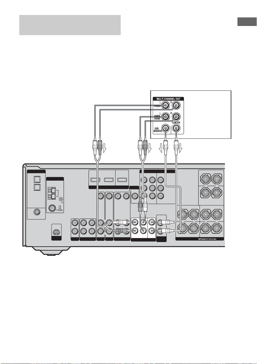
Connecting components with
multi channel output jacks
If your DVD or Super Audio CD player is
equipped with multi channel output jacks, you
can connect it to the MULTI CH IN jacks of
this receiver to enjoy multi channel sound.
Alternatively, the multi channel input jacks
can be used to connect an external multi
channel decoder.
Note
When you make connections to the MULTI CH IN
jacks, you will need to adjust the level of the
speakers and sub woofer using the controls on the
connected component.
DVD playe r,
Super Audio CD
player, etc.
Getting Started
AB
DVD IN
DIGITAL
OPTICAL
VIDEO 1
IN
VIDEO 2
IN
DVD
IN
COAXIAL
ANTENNA
D-LIGHT
SYNC OUT
AM
L
R
IN
OUT
SA-CD/CD
MD/TAPE
VIDEO 2 IN
ASSIGNABLE
HDMI
VIDEO IN
VIDEO IN
VIDEO OUT
L
L
R
R
AUDIO IN
AUDIO IN
DVD
VIDEO 2
AUDIO OUT
IN
A Audio cord (not supplied)
B Monaural audio cord (not supplied)
AB
MONITOR OUT
VIDEO IN
L
R
AUDIO IN
VIDEO 1
MONITOR
VIDEO OUT
FRONT
MULTI CH IN
COMPONENT VIDEO
ASSIGNABLE
DVDINVIDEO 2INMONITOR
L
R
SURROUND
CENTER
SUB
WOOFER
OUT
AUDIO
OUT
SUB
WOOFER
Y
PB/C
B
/B–Y
P
R/CR
/R–Y
CENTER
+
SURROUND BACK
L
+
R
SURROUND FRONT
SPEAKERS
L
–
+
R
–
–
19
GB
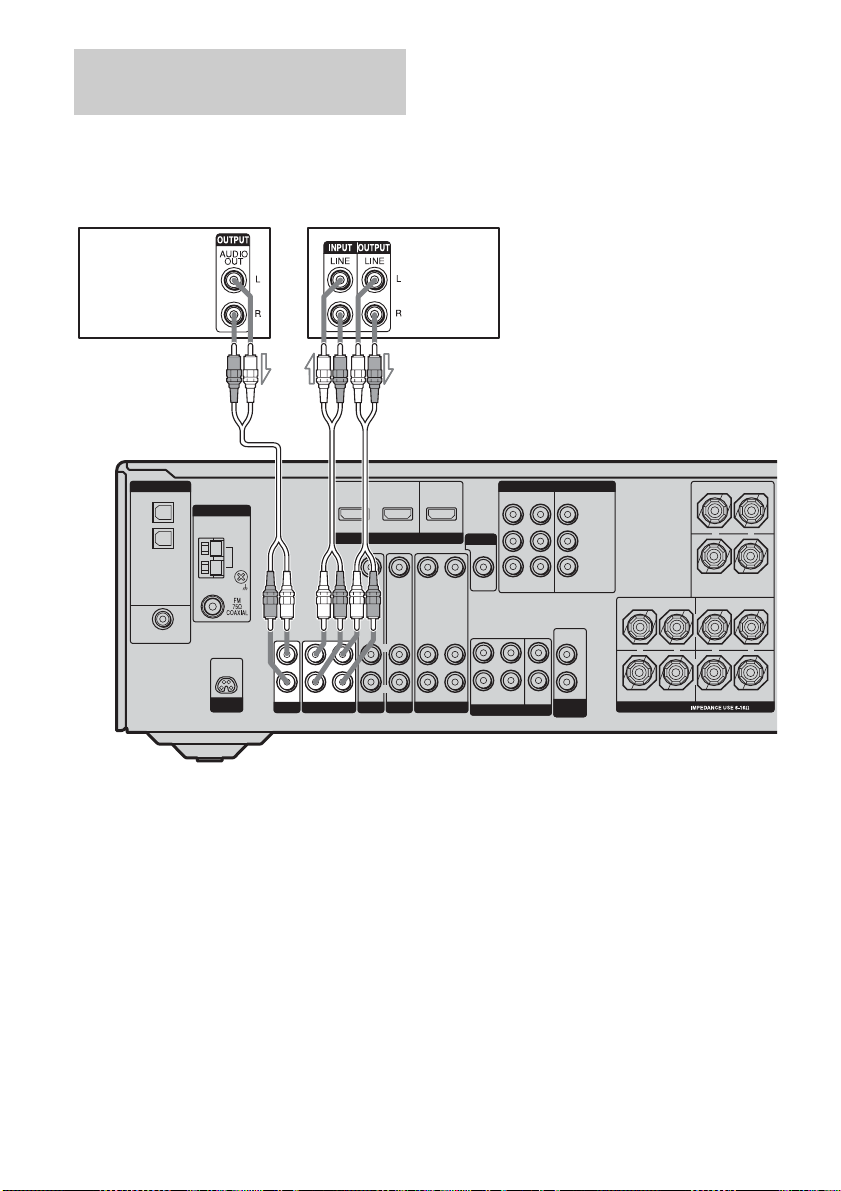
Connecting components with
analog audio jacks
The following illustration shows how to
connect a component which has analog jacks
such as tape deck, etc.
Super Audio
CD player/
CD player
A
AM
L
R
IN
SA-CD/CD
DIGITAL
OPTICAL
VIDEO 1
IN
VIDEO 2
IN
DVD
IN
COAXIAL
AA
ANTENNA
D-LIGHT
SYNC OUT
A Audio cord (not supplied)
L
R
OUT
MD/TAPE
DVD IN
IN
VIDEO 2 IN
ASSIGNABLE
VIDEO IN
L
R
AUDIO IN
DVD
MD deck/
Tape deck
HDMI
VIDEO IN
AUDIO IN
VIDEO 2
MONITOR OUT
VIDEO OUT
L
R
AUDIO OUT
VIDEO 1
VIDEO IN
AUDIO IN
MONITOR
VIDEO OUT
FRONT
MULTI CH IN
COMPONENT VIDEO
ASSIGNABLE
DVDINVIDEO 2INMONITOR
L
CENTER
R
SUB
SURROUND
WOOFER
OUT
AUDIO
OUT
SUB
WOOFER
Y
PB/C
B
/B–Y
P
R/CR
/R–Y
CENTER
+
SURROUND BACK
L
+
R
SURROUND FRONT
SPEAKERS
L
–
+
R
–
–
20
GB

3b: Connecting the video components
Getting Started
How to hook up your
components
This section describes how to hook up your
components to this receiver. Before you begin,
refer to “Component to be connected” below
for the pages which describe how to connect
each component.
After hooking up all your components,
proceed to “4: Connecting the antennas” (page
29).
Component to be connected
Component Page
TV monitor 22
DVD player/DVD recorder 23
Satellite tuner 26
With HDMI jack* 25
VCR 27
Camcorder, video game, etc. 27
* Except for models of area code MX, E51, AR.
Reassigning video input signals
to another input
Component video input signals and HDMI*
input signals can be reassigned to another
input (page 62, 63).
* Except for models of area code MX, E51, AR.
Video input/output jack to be
connected
The image quality depends on the connecting
jack. Refer to the illustration that follows.
Select the connection according to the jacks on
your components.
TV monitor, etc.
INPUT jack
Receiver
MONITOR OUT
Receiver INPUT
Video component
* Except for models of area code MX, E51, AR.
jack
jack
OUTPUT jack
Notes
• Connect image display components such as a TV
monitor or a projector to the MONITOR OUT jack
on the receiver.
• Turn on the receiver when the video and audio of a
playback component are being output to a TV
through the receiver. If the power supply of the
receiver is not on, neither video nor audio is
transmitted.
COMPONENT
VIDEO
HDMI*
COMPONENT
VIDEO
HDMI*
COMPONENT
VIDEO
HDMI*
COMPONENT
VIDEO
HDMI*
High quality image
VIDEO
VIDEO
VIDEO
VIDEO
21
GB
Hooking up a TV monitor
The image from a visual component connected
to this receiver can be displayed on a TV
screen.
It is not necessary to connect all the cables.
Connect video cords according to the jacks of
your components.
Notes
• Connect image display components such as a TV
monitor or a projector to the MONITOR OUT jack
on the receiver.
• Turn on the receiver when the video and audio of a
playback component are being output to a TV via
the receiver. If the power supply of the receiver is
not turned on, neither video nor audio is
transmitted.
Tip
You can watch the selected input image when you
connect the MONITOR OUT jack to a TV monitor.
TV monitor
BA
DVD IN
DIGITAL
OPTICAL
VIDEO 1
IN
VIDEO 2
IN
DVD
IN
COAXIAL
ANTENNA
D-LIGHT
SYNC OUT
AM
L
R
IN
OUT
SA-CD/CD
MD/TAPE
VIDEO 2 IN
ASSIGNABLE
HDMI
VIDEO IN
L
L
R
R
AUDIO IN
IN
DVD
VIDEO 2
A Video cord (not supplied)
B Component video cord (not supplied)
GB
22
VIDEO IN
AUDIO IN
MONITOR OUT
VIDEO OUT
L
R
AUDIO OUT
VIDEO 1
VIDEO IN
AUDIO IN
MONITOR
VIDEO OUT
FRONT
MULTI CH IN
COMPONENT VIDEO
ASSIGNABLE
DVDINVIDEO 2INMONITOR
L
CENTER
R
SUB
SURROUND
WOOFER
OUT
AUDIO
OUT
SUB
WOOFER
Y
PB/C
B
/B–Y
P
R/CR
/R–Y
CENTER
+
SURROUND BACK
L
+
R
SURROUND FRONT
SPEAKERS
L
–
+
R
–
–
Hooking up a DVD player/DVD
recorder
The following illustration shows how to
connect a DVD player/DVD recorder.
It is not necessary to connect all the cables.
Connect audio and video cords according to
the jacks of your components.
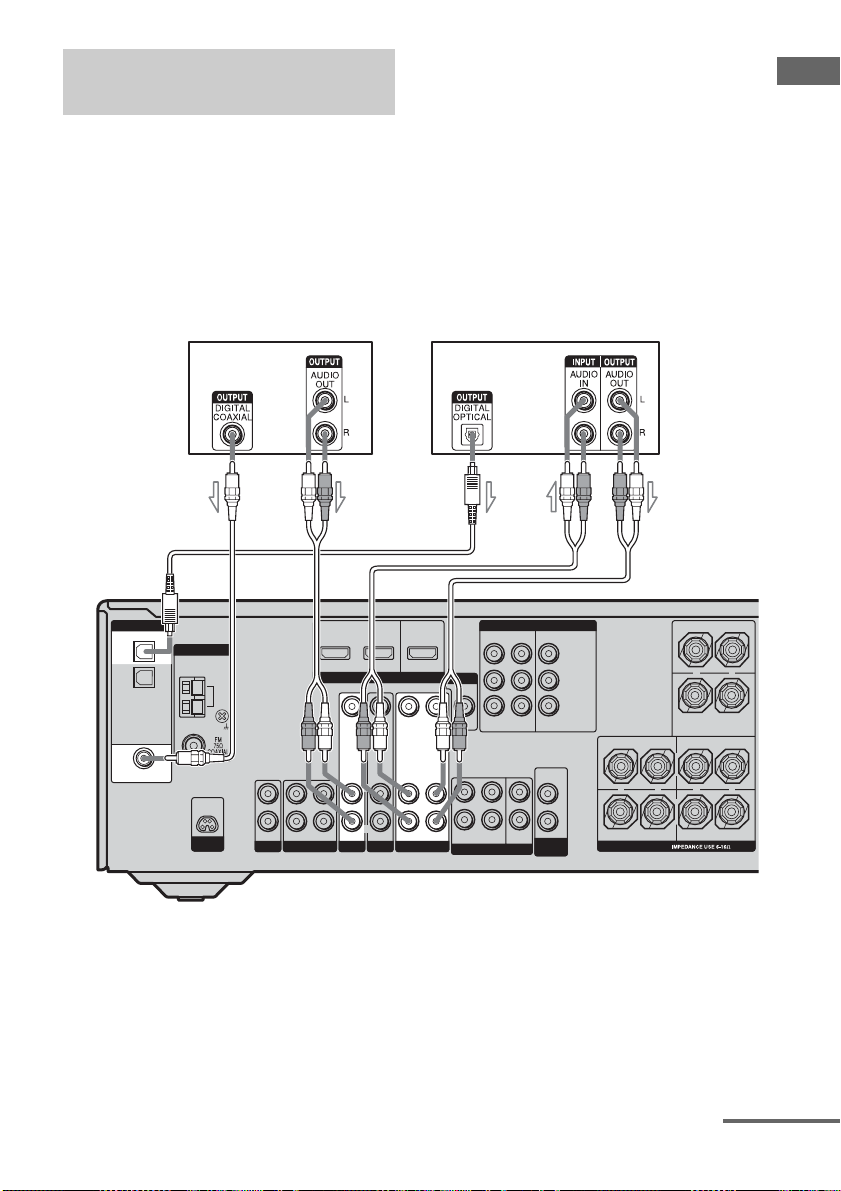
1 Connecting audio
Notes
• To input multi channel digital audio from the DVD
player, set the digital audio output setting on the
DVD player. Refer to the operating instructions
supplied with the DVD player.
• When connecting optical digital cords, insert the
plugs straight in until they click into place.
• Do not bend or tie optical digital cords.
Tip
All the digital audio jacks are compatible with
32 kHz, 44.1 kHz, 48 kHz, and 96 kHz sampling
frequencies.
Getting Started
DVD player
AB
DVD IN
DIGITAL
OPTICAL
VIDEO 1
IN
VIDEO 2
IN
DVD
IN
COAXIAL
ANTENNA
D-LIGHT
SYNC OUT
AM
L
R
IN
OUT
SA-CD/CD
MD/TAPE
VIDEO 2 IN
ASSIGNABLE
HDMI
VIDEO INVIDEO IN VIDEO IN
L
L
R
R
AUDIO IN
AUDIO IN
IN
DVD
VIDEO 2
A Coaxial digital cord (supplied)
B Audio cord (not supplied)
C Optical digital cord (not supplied)
DVD recorder
CB B
MONITOR OUT
VIDEO OUT
R
AUDIO OUT
VIDEO 1
L
AUDIO IN
MONITOR
VIDEO OUT
FRONT
MULTI CH IN
COMPONENT VIDEO
ASSIGNABLE
DVDINVIDEO 2INMONITOR
L
CENTER
R
SUB
SURROUND
WOOFER
OUT
AUDIO
OUT
SUB
WOOFER
Y
PB/C
B
/B–Y
P
R/CR
/R–Y
L
+
R
SURROUND FRONT
SPEAKERS
SURROUND BACK
–
CENTER
+
+
–
L
–
R
continued
23
GB
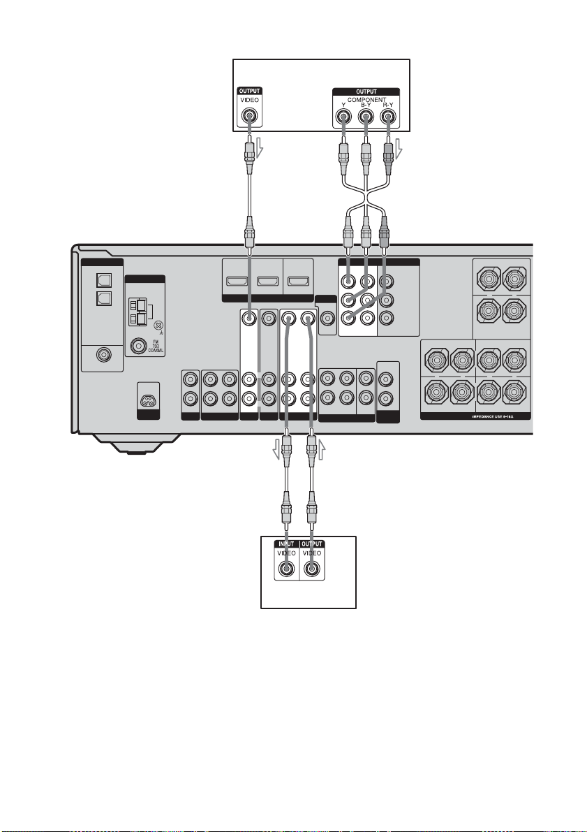
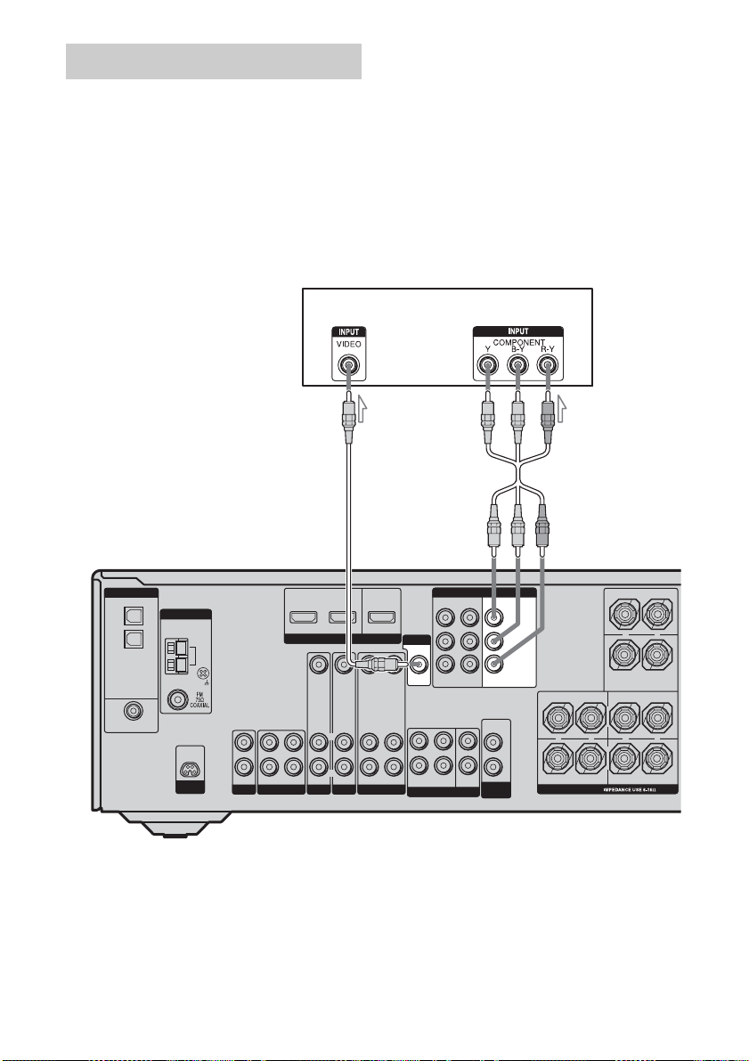
2 Connecting video
DVD playe r
DIGITAL
OPTICAL
VIDEO 1
IN
VIDEO 2
IN
DVD
IN
COAXIAL
ANTENNA
D-LIGHT
SYNC OUT
A
DVD IN
VIDEO 2 IN
MONITOR OUT
ASSIGNABLE
AM
L
R
IN
OUT
SA-CD/CD
MD/TAPE
HDMI
VIDEO IN
VIDEO IN
L
L
R
R
AUDIO IN
AUDIO IN
IN
DVD
VIDEO 2
VIDEO OUT
L
R
AUDIO OUT
VIDEO 1
VIDEO IN
AUDIO IN
MONITOR
VIDEO OUT
FRONT
L
R
SURROUND
MULTI CH IN
B
COMPONENT VIDEO
ASSIGNABLE
DVDINVIDEO 2INMONITOR
OUT
AUDIO
OUT
CENTER
SUB
WOOFER
WOOFER
SUB
Y
P
B/CB
/B–Y
P
R/CR
/R–Y
CENTER
+
SURROUND BACK
L
+
R
SURROUND FRONT
SPEAKERS
L
–
+
R
–
–
AA
DVD recorder
A Video cord (not supplied)
B Component video cord (not supplied)
If you connect a DVD recorder
• Be sure to change the factory setting of the
VIDEO 1 input button on the remote so that
you can use the button to control your DVD
recorder. For details, see “Programming the
remote” (page 67).
GB
24
• You can also rename the VIDEO 1 input so
that it can be displayed on the receiver’s
display. For details, see “Naming inputs”
(page 64).
 Loading...