

4-181-487-14(1)
Home Theatre System
HT-CT350
©2010 Sony Corporation
Operating Instructions
GB
CT

3
WARNING
The unit is not disconnected from the AC power source
(mains) as long as it is connected to the wall outlet,
even if the unit itself has been turned off.
To reduce the risk of fire, do not cover the ventilation
opening of the apparatus with newspapers, tablecloths,
curtains, etc.
Do not place the naked flame sources such as lighted
candles on the apparatus.
To reduce the risk of fire or electric shock, do not
expose this apparatus to dripping or splashing, and do
not place objects filled with liquids, such as vases, on
the apparatus.
As the main plug is used to disconnect the unit from the
mains, connect the unit to an easily accessible AC
outlet. Should you notice an abnormality in the unit,
disconnect the main plug from the AC outlet
immediately.
Do not install the appliance in a confined space, such as
a bookcase or built-in cabinet.
Do not expose batteries or apparatus with batteryinstalled to excessive heat such as sunshine, fire or the
like.
Precautions
On safety
• Should any solid object or liquid fall into the system,
unplug the system and have it checked by qualified
personnel before operating it any further.
• Do not climb on the subwoofer, as you may fall down
and injure yourself, or system damage may result.
On power sources
• Before operating the system, check that the operating
voltage is identical to your local power supply. The
operating voltage is indicated on the nameplate at the
rear of the subwoofer.
• If you are not going to use the system for a long time,
be sure to disconnect the system from the wall outlet
(mains). To disconnect the AC power cord (mains
lead), grasp the plug itself; never pull the cord.
• AC power cord (mains lead) must be changed only at
the qualified service shop.
On heat buildup
Although the system heats up during operation, this is
not a malfunction. If you continuously use this system
at a large volume, the system temperature of the back
and bottom rises considerably. To avoid burning
yourself, do not touch the system.
On placement
• Place the system in a location with adequate
ventilation to prevent heat buildup and prolong the
life of the system.
• Do not place the system near heat sources, or in a
place subject to direct sunlight, excessive dust, or
mechanical shock.
• Do not pl ace anything at the rear of the subwoofer th at
might block the ventilation holes and cause
malfunctions.
• Do not place the system near equipment such as a TV,
VCR, or tape deck. (If the system is being used in
combination with a TV, VCR, or tape deck, and is
placed too close to that equipment, noise may result,
and picture quality may suffer. This is especially
likely when using an indoor antenna. Therefore, we
recommend using an outdoor antenna.)
• Use caution when placing the system on surfaces that
have been specially treated (with wax, oil, polish, etc.)
as staining or discoloration of the surface may result.
GB
2
• Take care to avoid any possible
injury on the corners of the
subwoofer.
On operation
Before connecting other compo nents, be sure to turn off
and unplug the system.
If you encounter color irregularity on
a nearby TV screen
The system is magnetically shielded to allow it to be
installed near a TV set. However, color irregularities
may still be observed on certain types of TV sets.
If color irregularity is observed...
Turn off the TV set, then turn it on again after 15 to 30
minutes.
If color irregularity is observed
again...
Place the system further away from the TV set.
On cleaning
Clean the system with a soft dry cloth. Do not use any
type of abrasive pad, scouring powder or solvent such
as alcohol or benzine.
If you have any question or problem concerning your
system, please consult your nearest Sony dealer.
“BRAVIA Sync” is a trademark of Sony Corporation.
“PlayStation” is a registered trademark of Sony
Computer Entertainment Inc.
“x.v.Colour (x.v.Color)” and “x.v.Colour (x.v.Color)”
logo are trademarks of Sony Corporation.
GB
Copyrights
This system incorporates Dolby* Digital and Pro Logic
Surround and the DTS** Digital Surround System.
Manufactured under license from Dolby Laboratories.
*
Dolby, Pro Logic, and the double-D symbol are
trademarks of Dolby Laboratories.
** Manufactured under license under U.S. Patent #'s:
5,451,942; 5,956,674; 5,974,380; 5,978,762;
6,487,535 & other U.S. and worldwide patents
issued & pending. DTS and the Symbol are
registered trademarks & DTS Digital Surround and
the DTS logos are trademarks of DTS, Inc. Product
includes software. © DTS, Inc. All Rights Reserved.
This system incorporates High-Definition Multimedia
Interface (HDMI™) technology.
HDMI, the HDMI Logo, and High-Definition
Multimedia Interface are trademarks or registered
trademarks of HDMI Licensing LLC in the United
States and other countries.
GB
3

Table of contents
Precautions...............................................2
Getting Started
Unpacking................................................5
Positioning the system .............................7
Warning about installing the system’s
speaker to the TV stand or a wall ......9
Connecting the speaker ..........................21
Connecting the TV and player, etc. .......22
Connecting other components................24
Connecting the antenna (aerial) .............25
Connecting the AC power cord (mains
lead) .................................................26
Setting up the sound output of the
connected component ......................26
Playback Options
Index to parts and controls.....................27
Enjoying TV...........................................29
Enjoying other components ...................30
Tuner Functions
Direct tuning ..........................................32
Presetting radio stations .........................33
Listening to the radio .............................33
Naming preset stations...........................34
Viewing the station name or frequency in
the front panel display .....................35
Surround Function
Enjoying the surround effect..................36
“BRAVIA” Sync Features
What is “BRAVIA” Sync?.....................37
Preparing for “BRAVIA” Sync .............37
Enjoying Blu-ray Disc/DVD..................38
(One-Touch Play)
Enjoying the TV sound from the
system ..............................................39
(System Audio Control)
Turning off the system, TV and the
connected components.....................40
(System Power Off)
Using the power saving function ...........40
(HDMI SIGNAL PASS THRU)
Setting the Audio Return Channel function
to off................................................ 41
Advanced Settings
Controlling connected Sony components
with the remote ............................... 42
Changing the input button assignments of
the remote ....................................... 45
Settings and adjustments using the
amplifier menu................................ 47
Additional Information
Troubleshooting .................................... 51
Specifications........................................ 53
Index...................................................... 56
GB
4
Getting Started
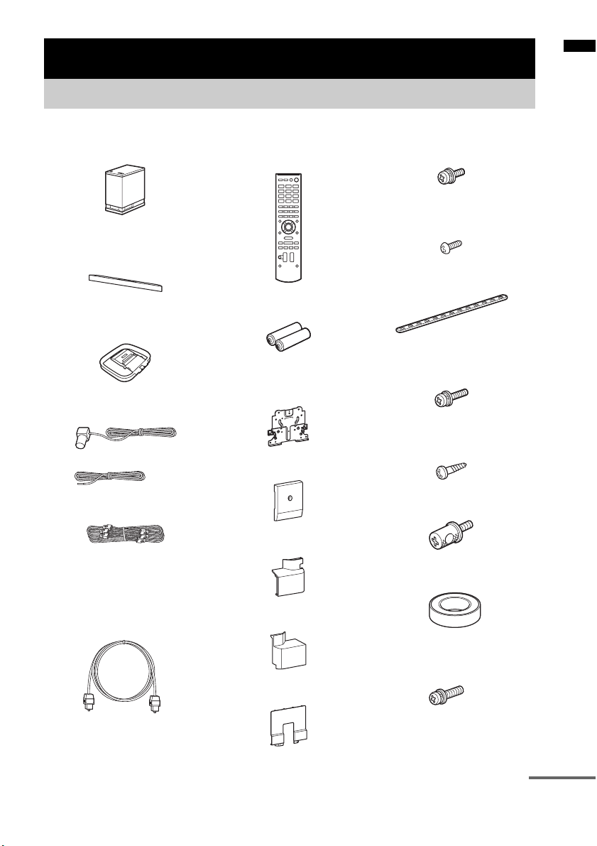
Unpacking
Getting Started
• Subwoofer (SA-WCT350) (1)
• Speaker (SS-CT350) (1)
• AM loop antenna (aerial) (1)
• FM wire antenna (aerial) (1)
or
• Speaker cord (1)
• Remote commander (RMAAU074) (1)
• R6 (size AA) batteries (2)
• WS-CT350EB
• Extension bracket (1)
• Rear cover A (1)
• Rear cover B (1)
• Screws for the ext ension bracket
(large, +PSW5 × 16 mm) (6)
• Screws for the rear cover (small,
M3 × 8 mm) (1)
• Support belt (1)
• Screw for the support belt
(+PSW4 × 20 mm) (1)
• Wood screw for the support belt
(M3.8 × 20 mm) (1)
•Clamp screw (2)
• Digital optical cord for a TV
(2.5 m) (1)
• Rear cover C (1)
• Cover for the TV (1)
• Spacer (4)
• Screw for the Wall-Mount
Bracket (+PSW6 × 22 mm) (4)
• Operating Instructions (1)
continued
GB
5
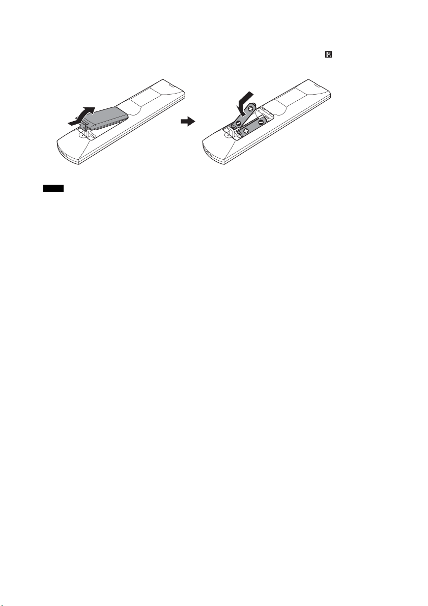
Inserting batteries into the remote
Insert two R6 (size AA) batteries (supplied) by matching the 3 and # ends on the batteries to the
markings inside the compartment. To use the remote, point it at the remote sensor in the front panel
display of the subwoofer.
Notes
• Do not leave the remote in an extremely hot or humid place.
• Do not use a new battery with an old one.
• Do not drop any foreign object into the remote casing, particularly when replacing the batteries.
• Do not expose the remote sensor to direct sunlight or lighting apparatus. Doing so may cause a malfunction.
• If you do not intend to use the remote for an extended period of time, remove the batteries to avoid possible damage
from battery leakage and corrosion.
GB
6
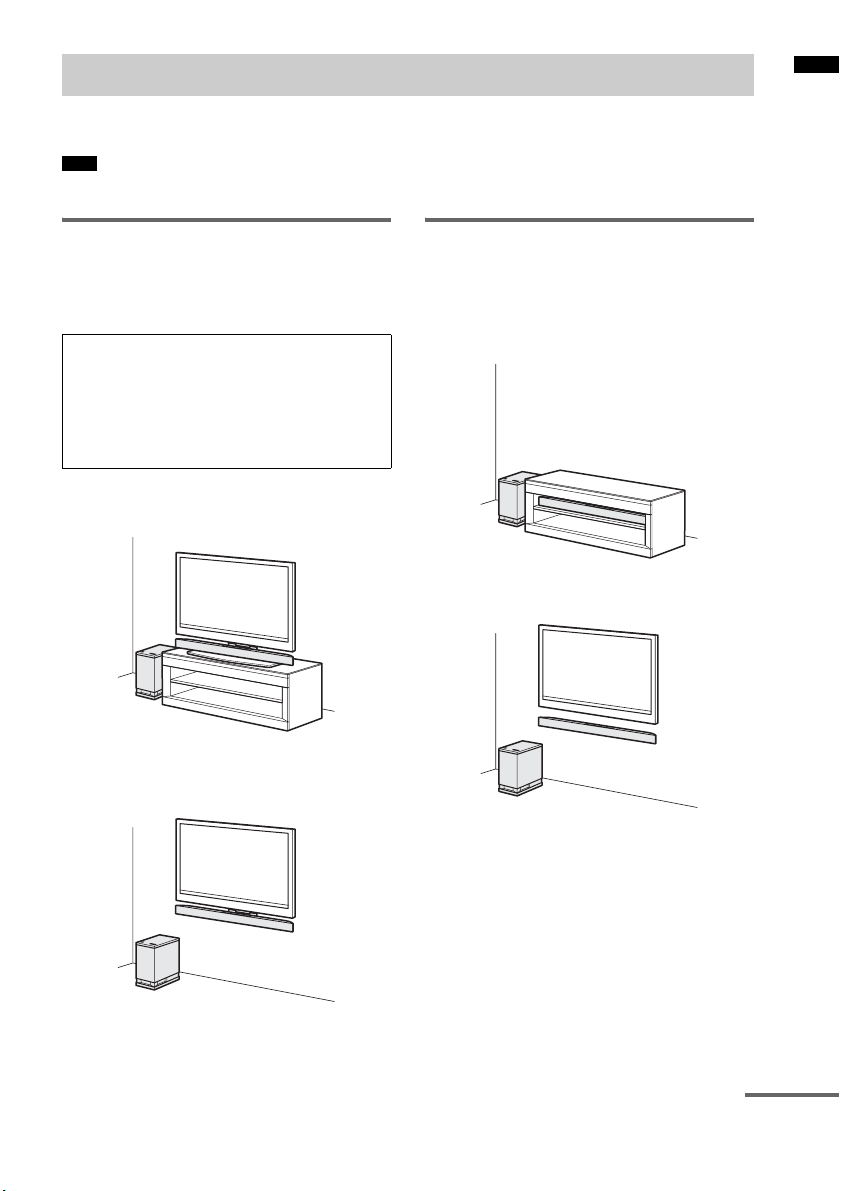
Positioning the system
The illustrations below are examples of how to install the subwoofer and speaker.
Note
• Do not block the heat ventilation on the rear panel of the subwoofer.
Getting Started
Installing the speaker to the
TV
You can install the speaker with the following
TV models (not supplied):
KDL-40NX800, KDL-46NX700,
KDL-40NX700, KDL-46HX800,
KDL-40HX800, KDL-46EX700,
KDL-40EX700, KDL-46EX710,
KDL-40EX710, KDL-40EX600,
KLV-40EX600
• Installing the speaker on the TV stand
(page 12)
• Hanging the speaker and TV on a wall
(page 15)
Installing the speaker and the
TV separately
If you cannot install the speaker to the TV, you
can install the speaker as shown below.
• Installing the speaker in a rack
• Installing the speaker on a wall (page 20)
continued
GB
7
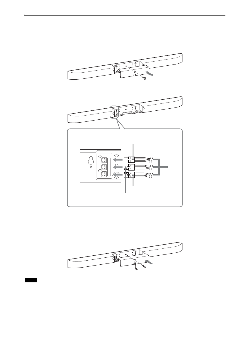
Connecting the speaker cord to the speaker
The connectors of the speaker cord are color-coded depending on the type of speaker. Connect the
connectors of the speaker cord to match the color of the speaker jacks.
1 Remove the screw of the cover at the rear of the speaker, and then remove the cover.
2 Connect the speaker cord.
Green
White
A
Red
A Speaker cord
(supplied)
Rear of the speaker
R CENTER L
3 Guide the speaker cord through the square notch at the bottom of the cover, and then
reattach the cover to the speaker and secure it with the screw removed in step 1.
If you install the speaker to the TV, do not reattach the cover. Perform the steps in “Installing the
speaker on the TV stand” (page 12), or “Hanging the speaker and TV on a wall” (page 15).
Notes
• When you install the speaker or a TV on a wall, be careful not to stumble over the cord connected to the speaker.
• Be careful not to pinch the speaker cord when you reattach the cover.
GB
8
Warning about installing the system’s speaker to the TV
stand or a wall
Getting Started
To Customers
Sufficient expertise is required for installing this
product. Be sure to subcontract the installation to
Sony dealers or licensed contractors and pay
special attention to safety during the installation.
Sony is not liable for any damages or injury
caused by mishandling or improper installation,
or installing anything other than the specified
product. Your statutory rights (if any) are not
affected.
On Safety
Products by Sony are designed with safety in
mind. If the products are used incorrectly,
however, it may result in a serious injury through
fire, electric shock, the product toppling over, or
the product dropping. Be sure to observe the
precautions for safety to prevent such accidents.
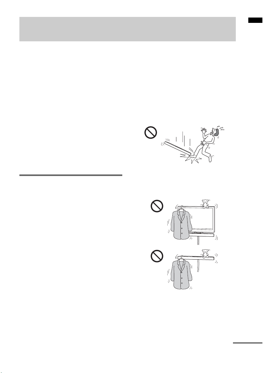
WARNING
If the following precautions are not observed,
serious injury or death through fire or electric
shock, the product toppling over or falling can
result.
Do not drop the products or install them
where there is a possibility of them falling
down.
• Be sure to subcontract installing, moving or
dismounting the products to licensed
contractors and keep small children away
during the procedure.
• Unauthorized installation may result in serious
injury or property damage.
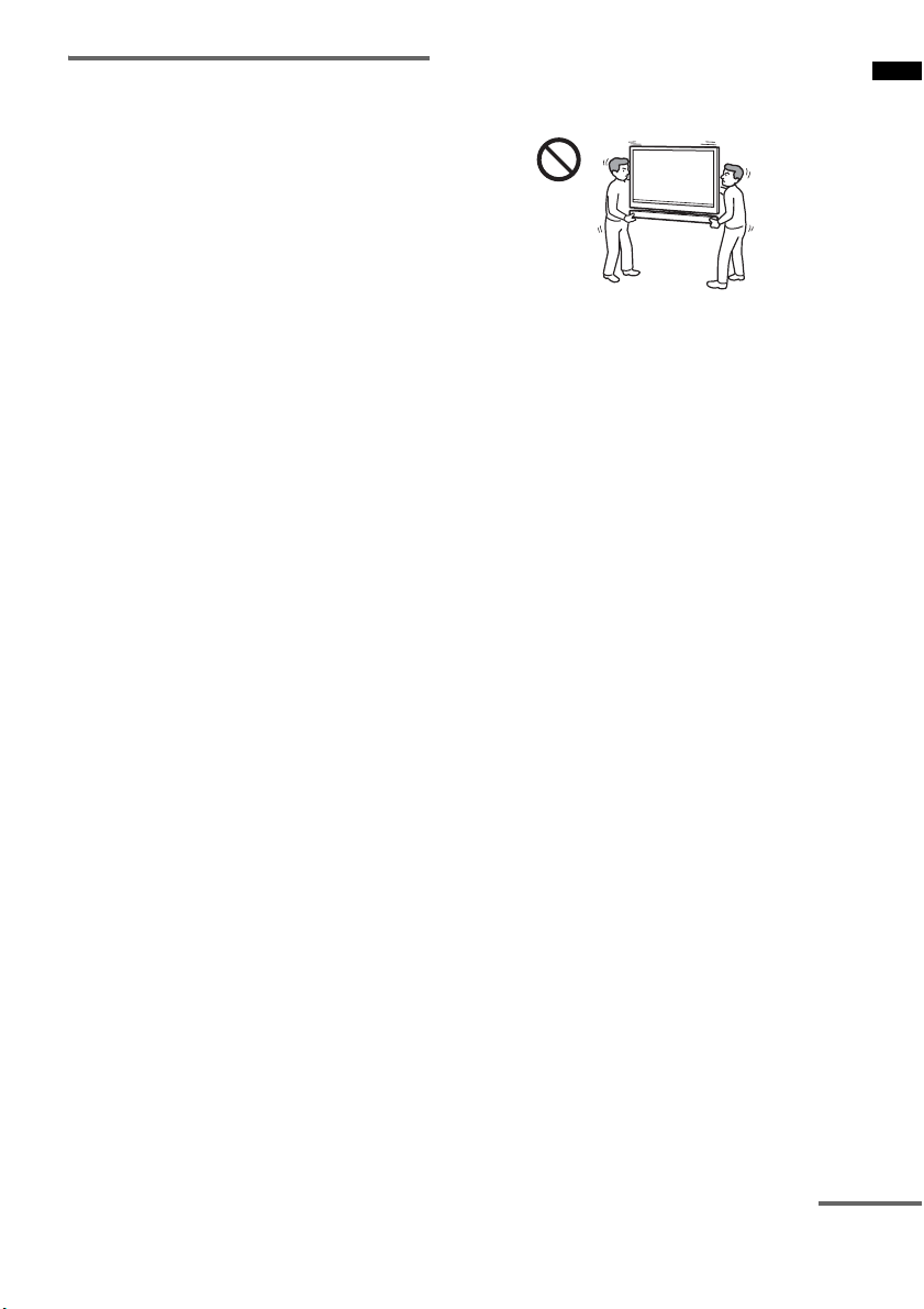
• Having an unauthorized dealer carry or
dismount the SS-CT350 speaker or SS-CT350
speaker-installed TV may lead to the products’
falling and result in serious injury or property
damage. Make sure that two or more persons
carry or dismount the product(s).
• Do not remove screws, etc., after mounting the
SS-CT350 speaker or SS-CT350 speakerinstalled TV.
• Do not handle the products with excessive
force during cleaning or maintenance.
• If you hang the SS-CT350 speaker or SSCT350 speaker-installed TV on a fragile wall
or a wall whose surface is not flat or
perpendicular, the product(s) may fall and
cause injury or property damage.
• If the SS-CT350 speaker or SS-CT350
speaker-installed TV is not installed firmly on
the wall, the product(s) may fall and cause
injury or property damage.
Do not place any object on the products.
• Do not put anything on the products. If you do
so, the system may fall and cause injury or
property damage.
continued
GB
9
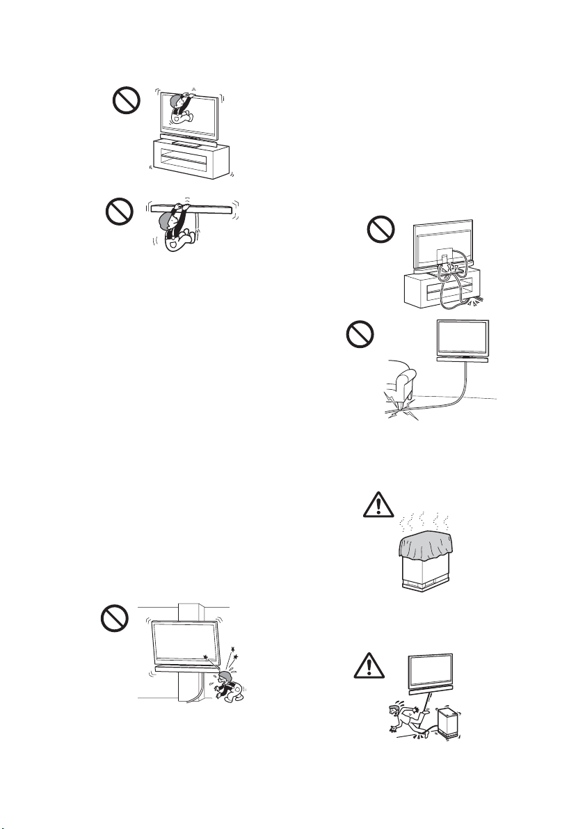
Do not lean or hang on the products.
• Do not lean or hang on the products, as they
may fall on you and cause serious injury.
Pay attention to the location.
• Do not install the products on wall surfaces
such as a pillar, where the corners or the sides
of the products protrude away from the wall
surface. If a person or object happens to hit the
protruded corner or side of the products, it may
cause injury or property damage.
• Do not expose the products to rain or moisture,
or spill liquid of any kind on them. It may cause
a fire or electric shock.
• Never place the products in hot, humid or
excessively dusty places, or in a place where
they are subject to mechanical vibrations.
Doing so may cause a fire or electric shock.
• Keep flammable objects or open flames (e.g.,
candles) away from the products.
• Do not install the products over or under an airconditioner. If the products are exposed to
wind from the air conditioner for an extended
period of time, or get wet by water leakage
from the air conditioner, this may cause a fire,
an electric shock, or malfunctions.
Do not allow the cords to be pinched.
• If the AC power cord (mains lead) or
connecting cords are pinched between the
products and the wall, floor, or other object, or
bent or twisted by force, the internal
conductors may become exposed and cause a
short circuit or an electrical break. This may
cause a fire or an electric shock.
• Do not step on the AC power cord (mains lead)
or connecting cords when you carry the
products. The cord may be damaged, and this
may result in a fire or electric shock.
Do not cover the ventilation holes of the
products.
• If you cover the ventilation holes (with a cloth,
etc.), heat may build up inside and cause a fire.
Do not stumble over the cords.
• You may trip, or may cause the products to
topple over and cause injury.
10
GB
CAUTION
If the following precautions are not observed,
injury or property damage may occur.
Do not install any equipment other than the
specified product.
• The WS-CT350EB accessories (supplied) are
designed for use with the specified equipment
only. If you install equipment other than that
specified, it may fall or break, and cause injury.
• Do not modify the products.
• Do not place anything hot directly on the
products. The heat may cause discoloration or
deformation of the products.
Be sure to secure the system’s speaker and
TV.
• Secure the SS-CT350 speaker and TV firmly
when installing them together. Then, secure the
SS-CT350 speaker-installed TV firmly on the
stand or wall. If the SS-CT350 speaker and TV
are not installed securely, they may fall or
topple over, and cause injury.
Do not apply weight to the products or
subject them to any kind of impact.
• When installing the SS-CT350 speaker to a TV
stand or hanging the SS-CT350 speaker installed TV on a wall, do not apply weight to
the speaker or TV with your hand. Do not hit
the speaker or TV with hard objects, such as a
screwdriver, etc.
When moving the SS-CT350 speakerinstalled TV
If you move the products forcefully, damage or
injury may result. Be sure to follow the proper
procedures and advice given below.
• Be sure that two or more persons carry the SSCT350 speaker-installed TV, and only after
unplugging and removing the connected
equipment.
• Be careful not to allow your hands or feet to be
pinched under the bottom of the SS-CT350
speaker-installed TV.
• When carrying the SS-CT350 speakerinstalled TV, do not hold it by the SS-CT350
speaker part. Doing so may cause damage or
injury.
• Do not drag the SS-CT350 speaker-installed
TV. The base part may come off and damage
the floor.
Notes on installation
• When assembling, spread a cloth on the floor to
avoid damaging the floor.
• Install the products on a solid and flat floor.
• Be sure that two or more persons install the
products. Doing it alone may result in an
accident or injury.
• Be sure to keep children away during the
process.
Be sure to install the products securely
following the instructions.
• Tighten the screws securely. If the SS-CT350
speaker is not installed securely, it may fall and
cause damage or injury.
• Be careful not to pinch your fingers or hands
when assembling the products.
Notes on installation on a wall
• If you use the products installed on a wall for a
long time, the wall behind or above the
products may become discolored or the
wallpaper may come unstuck, depending on
the material of the wall.
• If the products are removed after installed on
the wall, the screw holes will remain.
• Consult your licensed contractor regarding an
appropriate location (free from radio noise,
etc.) before installing.
Getting Started
continued
11
GB
Installing the speaker on the TV stand
You can install the speaker with the following TV models (not supplied):
• KDL-40NX800, KDL-46NX700, KDL-40NX700, KDL-46HX800, KDL-40HX800,
KDL-46EX700, KDL-40EX700, KDL-46EX710, KDL-40EX710, KDL-40EX600, KLV-40EX600
Although the shape of the TV stand base differs depending on the TV model, you can install the speaker
on the TV stand following this procedure.
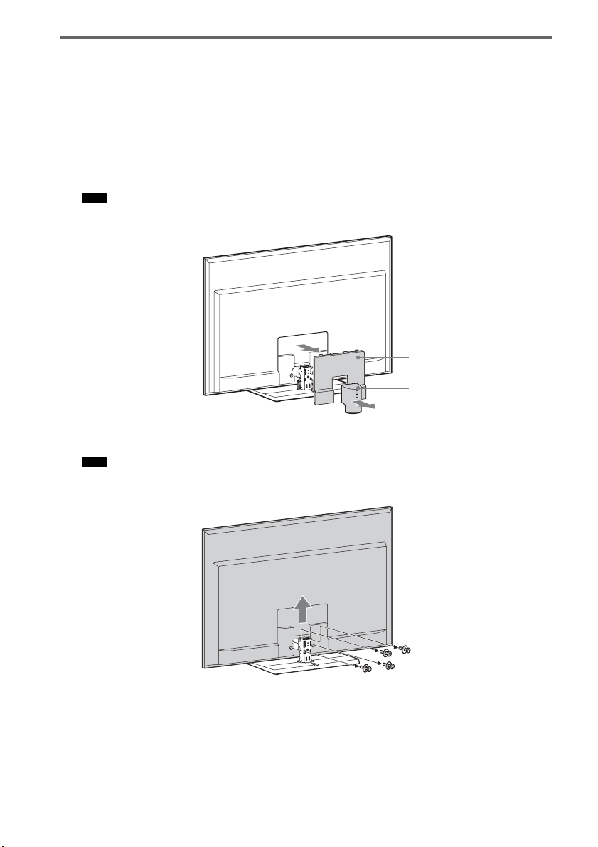
1 Remove covers 1 and 2 from the rear of the TV.
For details on removing the covers, refer to the operating instructions of the TV.
Note
• Some Sony TVs do not have cover 2.
Cover 2
Cover 1
2 Remove the screws of the TV, and then detach the TV from the TV stand.
Note
• Make sure to place the TV on a soft thick cloth with the screen side down to prevent damaging the surface of
the LCD.
12
GB
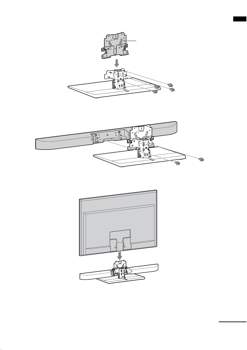
3 Secure the extension bracket (supplied) to the TV stand with the large screws (+PSW5
× 16 mm) (supplied).
Extension bracket
4 Secure the speaker to the extension bracket with the large screws (+PSW5 × 16 mm)
(supplied).
5 Reattach the TV.
Getting Started
continued
13
GB
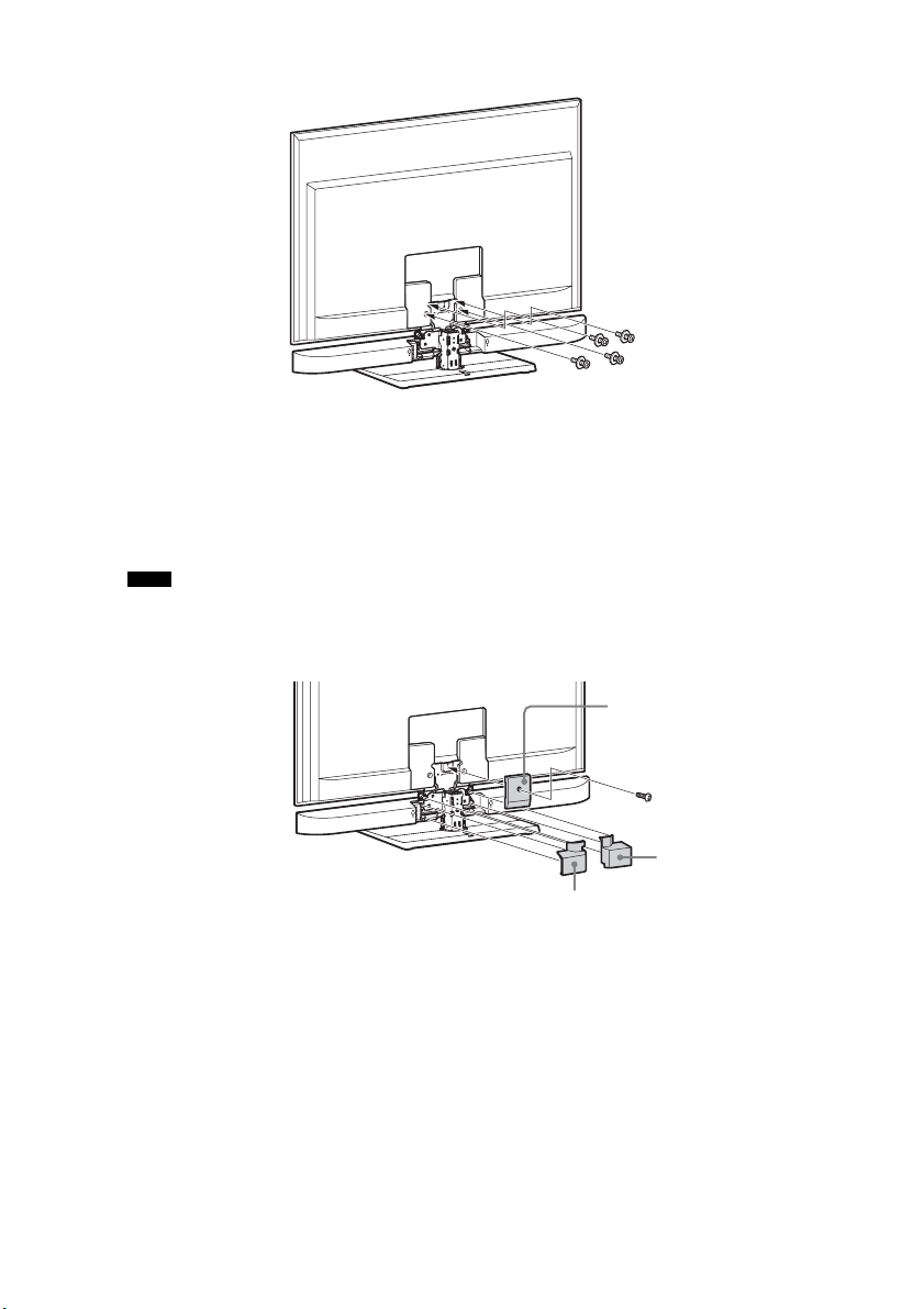
6 Secure the TV with the screws removed in step 2.
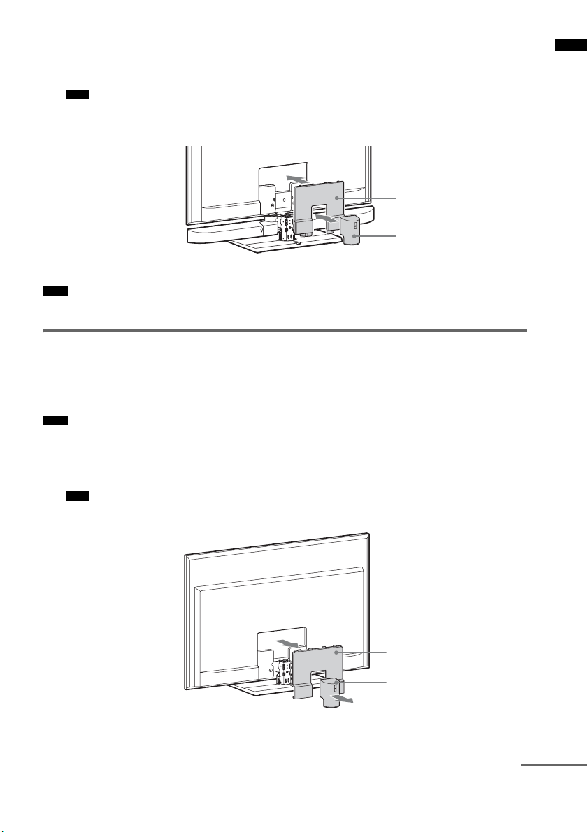
7 Attach the rear covers A, B, and C (supplied).
Secure the rear cover A to the extension bracket with the small screw (M3 × 8 mm) (supplied).
Guide the speaker cord through the rectangular notch of the rear cover B, and insert the three
projecting parts of the rear cover B into the holes on the extension bracket and the speaker.
Insert the three projecting parts of the rear cover C into the holes on the extension bracket and the
speaker.
Notes
• When carrying the SS-CT350 speaker-installed TV, do not hold it by the SS-CT350 speaker part. Doing so
may cause damage or injury.
• The rear cover A is used only for the following TV model: KDL-40NX800, KDL-40/46NX700.
14
Rear cover A
Rear cover C
Rear cover B
GB
8 Attach the cover for the TV (supplied) and cover 1 removed in step 1.
Insert the two projecting parts of the cover for the TV into the holes on the TV.
For details on attaching cover 1, refer to the operating instructions of the TV.
Note
• The cover for the TV is used only for the following TV m odel: KDL-40NX800 (You can attach cover 2 instead
if it was supplied with your TV.)
Cover for the TV
Cover 1
Note
• As a protective measure, secure the TV. For details, see “Preventing the TV from toppling over” (page 18).
Hanging the speaker and TV on a wall
You can hang the speaker with the following TV models (not supplied):
• KDL-40NX800, KDL-46NX700, KDL-40NX700, KDL-46HX800, KDL-40HX800,
KDL-46EX700, KDL-40EX700, KDL-46EX710, KDL-40EX710, KDL-40EX600, KLV-40EX600
Note
• To hang the TV on the wall, refer to the operating instructions of the TV and the Wall-Mount Bracket.
1 Remove covers 1 and 2 from the rear of the TV.
For details on removing the covers, refer to the operating instructions of the TV.
Note
• Some Sony TVs do not have cover 2.
Getting Started
Cover 2
Cover 1
continued
15
GB
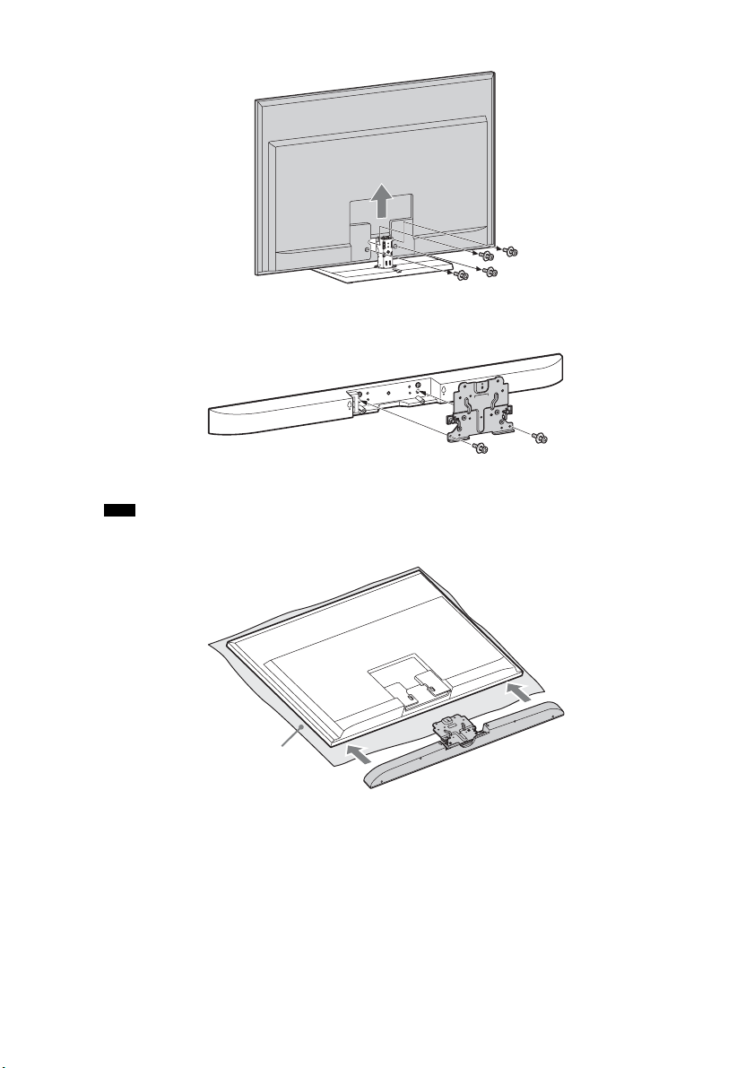
2 Remove the screws of the TV, and then detach the TV from the TV stand.
3 Secure the speaker to the extension bracket with the large screws (+PSW5 × 16 mm)
(supplied).
4 Reattach the TV.
Note
• Make sure to place the TV on a soft thick cloth with the screen side down to prevent damaging the surface of
the LCD.
16
Cloth
GB
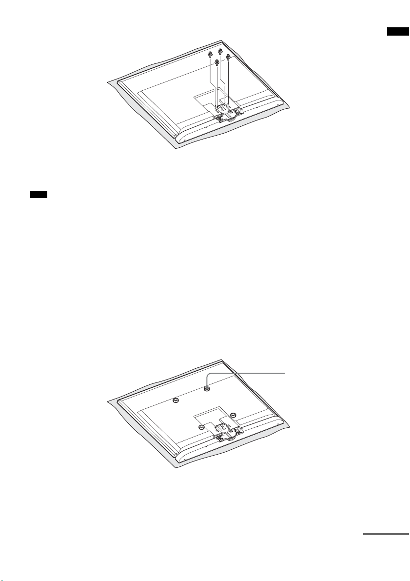
5 Secure the TV with the screws removed in step 2.
6 Hang the TV on the wall.
For details on hanging the TV on the wall, refer to the operating instructions of the TV.
Note
• When hanging the SS-CT350 speaker-installed TV on the wall or taking it off the wall, do not hold it by the SSCT350 speaker part. Doing so may cause damage or injury.
When hanging TV model KDL-46HX800, KDL-40HX800, KDL-46EX700,
KDL-40EX700, KDL-46EX710, KDL-40EX710, KDL-40EX600, KLV40EX600 using the Wall-Mount Bracket (SU-WL500, not supplied)
You can only adjust the angle of the SS-CT350 speaker-installed TV to 0° or 5° downward. If you want
to set the TV’s angle to 10°, 15° or 20° downward, install the SS-CT350 speaker directly on the wall.
When hanging TV model KDL-40NX800, KDL-46NX700, KDL-40NX700
using the Wall-Mount Bracket (SU-WL700, not supplied)
Place the Spacers (supplied) between the TV and the Wall-Mount Bracket, and then secure them using
the Screws for the Wall-Mount Bracket (supplied).
Use the Spacers and Screws for the Wall-Mount Bracket supplied with the system. Do not use spacers
supplied with certain TVs.
Getting Started
Spacer
continued
17
GB
Preventing the TV from toppling over
As a protective measure, secure the TV. If you fail to do so, the TV may topple over resulting in serious
injury.
Warning
• To avoid injury, place the SS-CT350 speaker-installed TV less than 25 cm from the wall, and firmly secure the TV
to the wall.
Notes
• Be careful not to pinch your fingers when setting up the TV or rack.
• Install the TV after allowing for a space of less than 25 cm from the wall. The wall will prevent the TV from falling
even if the TV leans backward towards the wall.
When installing the TV on a rack
Screw for the support belt
(+PSW4 × 20 mm)
Wood screw for the support belt
(M3.8 × 20 mm)
1 Place the TV on the center of the rack.
2 Fit the support belt (supplied) to the TV, then firmly fasten with the screw for the support
belt (+PSW4 × 20 mm) (supplied) using a screw driver.
3 Fasten the support belt to the rack with the wood screw for the support belt (M3.8 × 20
mm) (supplied).
GB
18
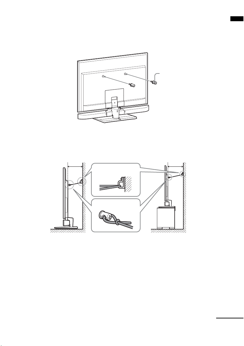
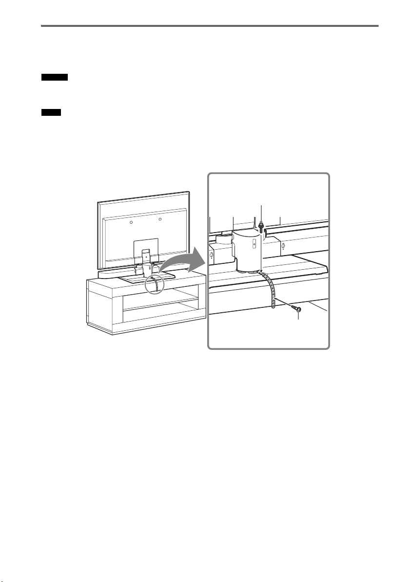
Securing the TV to a wall
Prepare strong string or chain (not supplied) and a fastener (not supplied) for fastening to the wall.
Secure the fastener to a reinforced wall.
Even if you have secured the TV to the rack, be sure to secure it to a wall following this procedure.
1 Fasten the clamp screws (supplied) to the rear of the TV.
Clamp screw
2 Secure the fastener to the wall (1), and then thread the string or chain through the holes
of the clamp screws and the fastener (2). Firmly tie both ends of the string or chain
together.
Less than
25 cm
1
Less than
25 cm
Getting Started
2
TV installed on the floor TV installed on a rack
continued
19
GB
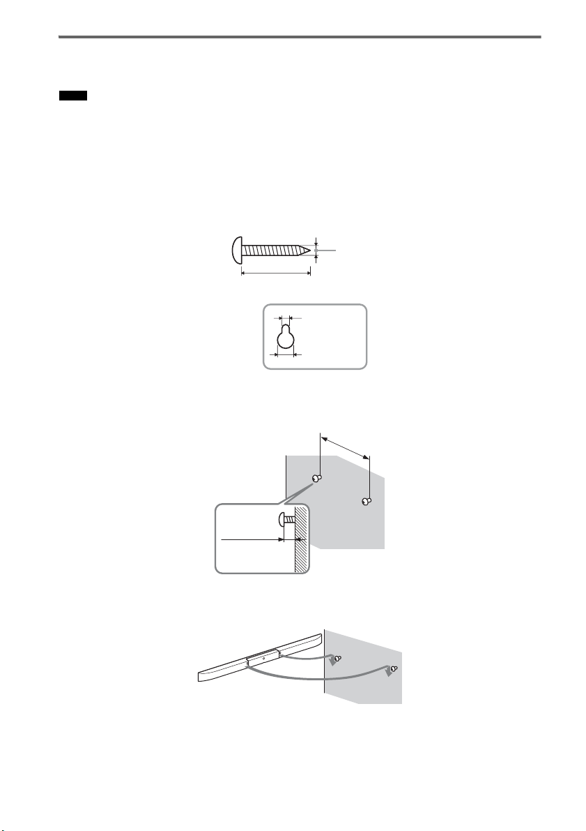
Installing the speaker on a wall
You can install the speaker on the wall.
Notes
• Use screws that are suitable for the wall material and strength. As a plaster board wall is especially fragile, attach
the screws securely to a wall beam. Install the speaker on a vertical and flat reinforced area of the wall.
• Be sure to subcontract the installation to Sony dealers or licensed contractors and pay special attention to safety
during the installation.
• Sony is not responsible for accidents or damage caused by improper installation, insufficient wall strength,
improper screw installation or natural calamity, etc.
1 Prepare screws (not supplied) that are suitable for the holes on the back of the speaker.
See the illustrations below.
4mm
more than 25 mm
5mm
10 mm
Hole on the back of the speaker
2 Fasten the screws to the wall. The screws should protrude 6 to 7 mm.
265 mm
6 to 7 mm
3 Hang the speaker onto the screws.
Align the holes on the back of the speaker to the screws, then hang the speaker onto the two screws.
GB
20

Connecting the speaker
The connectors of the speaker cord are color-coded depending on the type of speaker. Connect the
connectors of the speaker cord to match the color of the SPEAKERS jacks.
Rear of the
subwoofer
DMPORT
DC 5V
0.7A MAX
Green
Red White
Speaker
L
ONLY FOR
SS-CT350
A
AUDIO I N
SA-CD/CD
SAT/CATV INBD INDVD IN
HDMI
L
R
AUDIO I N
ANTENNA
FM
75 COAXIAL
OPT IN
TV OUT
TVSAT/CATVR CENTER
AM
ARC
COAX IN
VIDEO
TV
DIGITALSPEAKERS
Getting Started
A Speaker cord (supplied)
21
GB

Connecting the TV and player, etc.
Connect the TV and/or player, etc., with HDMI jacks to the system using an HDMI cable.
By connecting Sony “BRAVIA” Sync-compatible components using HDMI cables and by setting the
Control for HDMI function via the TV for each connected component, operation can be simplified. See
““BRAVIA” Sync Features” (page 37).
DVD player, etc.
HDMI OUT
HDMI cable
(not supplied)
HDMI cable
(not supplied)
TV
HDMI IN
Rear of the
subwoofer
Blu-ray Disc player, etc.
HDMI OUT
DMPORT
DC 5V
0.7A MAX
L
HDMI cable
(not supplied)
ONLY FOR
SS-CT350
AUDIO I N
SA-CD/CD
SAT/CATV INBD INDVD I N
L
ANTENNA
R
AUDIO I N
75 COAXIAL
TV
HDMI
DIGITALSPEAKERS
OPT IN
Digital optical cord
(not supplied)
FM
TV OUT
TVSAT/CATVR CENTER
AM
ARC
COAX IN
VIDEO
HDMI cable
(not supplied)
Digital Audio OUT
(optical)
Digital optical cord fo r a TV
(supplied)
Satellite tuner or cable television
tuner, etc., with an HDMI jack
Digital Audio OUT
(optical)
HDMI OUT
22
GB

Notes
• The system is compatible with the Audio Return Channel (ARC) function. If you connect the system to the ARCcompatible TV’s HDMI jack via an HDMI cable, you do not need to connect the TV to the system with the digital
optical cord (page 41).
• You can see the letters “ARC” beside the TV’s HDMI jack if it is compatible with the ARC function. Even if you
connect an HDMI cable to the jack, if the HDMI input jack is not compatible with the ARC function, you cannot
use the ARC function.
• The ARC function is available only when Control for HDMI is set to on.
• Depending on the satellite tuner, multi-channel sound may not be output. In this case, connect a digital optical cord
in addition to an HDMI cable and set “INPUT MODE” to “OPT” in the AMP menu (page 49).
• Connect a “PlayStation 3,” etc., to any available HDMI jack. All the HDMI jacks on the system function in the same
way.
• The HDMI jack connections have priority when you connect different components to the system using the INPUT
OPT/INPUT COAX and HDMI jacks.
• When connecting a TV that does not have a digital optical audio output jack, connect the TV to the system using
an analog audio cord (not supplied).
Tip
• Even if the system is tu rned off (active standby mode), the HDMI signal will be sent from the connected component
to the TV via the HDMI connection. You can enjoy image and sound from the component on the TV.
Notes on HDMI connections
• Use a High Speed HDMI cable. If you use a Standard HDMI cable, 1080p, Deep Colour, or 3D
images may not be displayed properly.
• Sony recommends that you use an HDMI-authorized cable or Sony HDMI cable.
• Check the setup of the connected component if an image is poor or the sound does not come out of a
component connected via the HDMI cable.
• Audio signals (sampling frequency, bit length, etc.) transmitted from an HDMI jack may be
suppressed by the connected component.
• Sound may be interrupted when the sampling frequency or the number of channels of audio output
signals from the playback component is switched.
• When the connected component is not compatible with copyright protection technology (HDCP), the
image and/or the sound from the HDMI TV OUT jack may be distorted or may not be output.
In this case, check the specification of the connected component.
• We do not recommend using an HDMI-DVI conversion cable.
• When “TV,” “DMPORT,” “SA-CD/CD,” “VIDEO,” “TUNER FM,” or “TUNER AM” is selected
for the input source of the system, video signals via the HDMI input jack (BD, DVD, SAT/CATV)
that was selected last time are output from the HDMI TV OUT jack.
• This system supports Deep Colour, “x.v.Colour,” and 3D transmission.
• To enjoy 3D images, connect 3D-compatible TV and video components (Blu-ray Disc player, Blu-
ray Disc recorder, “PlayStation 3,” etc.) to the system using High Speed HDMI cables, put on 3D
glasses, and then play back 3D-compatible content.
Getting Started
23
GB
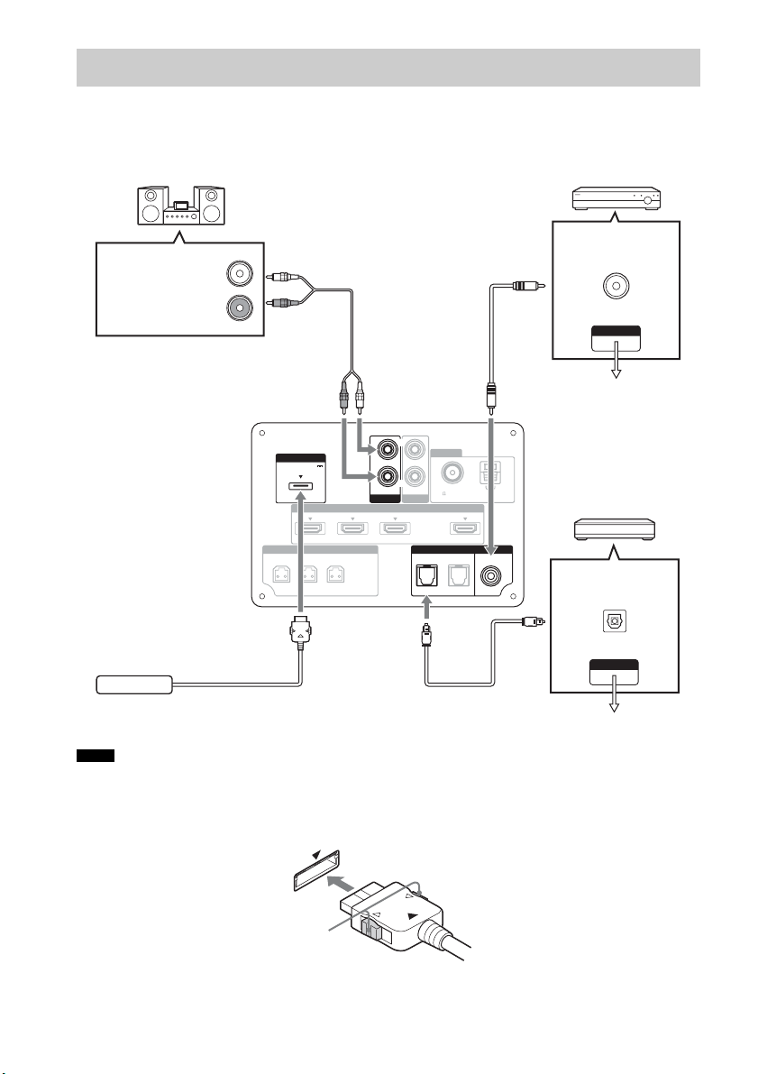
Connecting other components
When connecting components that do not have HDMI jacks, such as a “PlayStation 2,” a DVD player,
a satellite tuner, or a cable television tuner, etc., set “CTRL HDMI” to “OFF” in the AMP menu of the
system (page 38).
Other audio components, etc.
DVD player, etc.
Audio cord
(not supplied)
Digital coaxial cord
(not supplied)
Digital Audio OUT
(coaxial)
Audio signal OUT
VIDEO OUT
To the VIDEO IN of
the TV.
Rear of the
DIGITAL MEDIA
PORT adapter
Notes
subwoofer
DMPORT
DC 5V
0.7A MAX
L
ONLY FOR
SS-CT350
AUDIO I N
SA-CD/CD
SAT/CATV INBD INDVD IN
HDMI
L
R
AUDIO I N
TV
ANTENNA
FM
75 COAXIAL
AM
ARC
TV OUT
DIGITALSPEAKERS
COAX IN
OPT IN
TVSAT/CATVR CENTER
VIDEO
Digital optical cord
(not supplied)
Satellite tuner or cable
television tuner, etc.,
without an HDMI jack
Digital Audio OUT
(optical)
VIDEO OUT
To the VIDEO IN of the TV.
• Do not connect or disconnect the DIGITAL MEDIA PORT adapter while the system is turned on.
• When you connect the DIGITAL MEDIA PORT adapter, be sure the connector is inserted with the arrow mark
facing toward the arrow mark on the DMPORT jack. To detach the DIGITAL MEDIA PORT adapter, press and
hold A and then pull out the connector.
24
A
GB
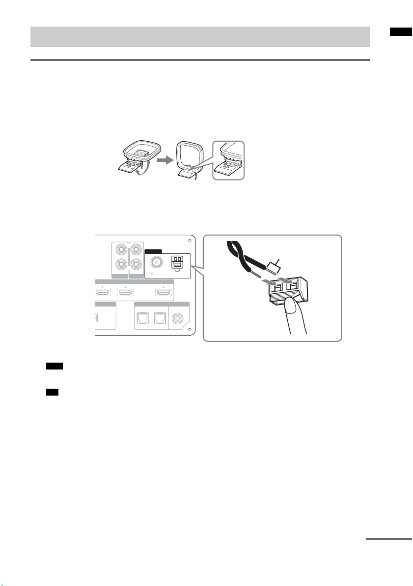
Connecting the antenna (aerial)
Connecting the AM loop antenna (aerial)
The shape and the length of the antenna (aerial) is designed to receive AM signals. Do not dismantle
or roll up the antenna (aerial).
1 Remove only the loop part from the plastic stand.
2 Set up the AM loop antenna (aerial).
3 Connect the cords to the AM antenna (aerial) terminals.
While pushing down the terminal clamp, insert the (*) part of the cords.
The cords can be connected to either terminal.
Rear of the
subwoofer
ONLY FOR
SS-CT350
AUDIO I N
SA-CD/CD
SAT/CATV INBD IN
HDMI
L
R
AUDIO I N
TV
ANTENNA
FM
75 COAXIAL
DIGITAL
OPT IN
TV OUT
TVSAT/CATV
*
AM
ARC
COAX IN
VIDEO
Getting Started
Note
• Do not place the AM loop antenna (aerial) near the system or other AV component, as noise may result.
Tip
• Adjust the direction of the AM loop antenna (aerial) for best AM broadcast sound.
4 Make sure the AM loop antenna (aerial) is connected firmly by pulling softly on the cord.
continued
25
GB

Connecting the FM wire antenna (aerial)
Connect the FM wire antenna (aerial) to the FM 75 Ω COAXIAL jack.
Rear of the
subwoofer
Notes
ONLY FOR
SS-CT350
AUDIO I N
SA-CD/CD
SAT/CATV INBD IN
HDMI
L
ANTENNA
R
FM
AUDIO I N
75 COAXIAL
DIGITAL
OPT IN
TV OUT
TVSAT/CATV
AM
ARC
FM wire antenna
COAX IN
VIDEO
(aerial)
(supplied)
TV
• Be sure to fully extend the FM wire antenna (aerial).
• After connecting the FM wire antenna (aerial), keep it as horizontal as possible.
• Do not use the FM wire antenna (aerial) while it is bundled up.
• Insert the FM wire antenna (aerial) fully and firmly to the terminal.
Tip
• If you have poor FM reception, use a 75-ohm coaxial cable (not supplied) to connect the subwoofer to an outdoor
FM antenna (aerial) as shown below.
FM 75 Ω COAXIAL jack
or
Rear of the
ANTENNA
subwoofer
FM
75 COAXIAL
Outdoor FM antenna
AM
(aerial)
Connecting the AC power cord (mains lead)
Before connecting the AC power cord (mains lead) of the system to a wall outlet (mains), connect all
the other components and TV to the system.
Notes
• After connecting the AC power cord (mains lead), wait about 20 seconds before turning on the power by pressing
?/1.
• Connect the system to an easily accessible AC outlet (mains). Should you notice an abnormality in the system,
disconnect the main plug from the AC outlet (mains) immediately.
Setting up the sound output of the connected component
To enjoy sound in multi-channel format (DTS, Dolby Digital, multi-channel LPCM), you need to make
the audio output settings of the connected component. Set the connected component to output sound in
multi-channel format. For details on audio output settings, refer to the operating instructions supplied
with the connected component.
GB
26

Playback Options
Index to parts and controls
For more information, see the pages indicated in parentheses.
Subwoofer
Top view
POWER/
ACTIVE STANDBY
INPUT
SELECTOR
Playback Options
VOLUME VOLUME
A ?/1 (on/standby)
B INPUT SELECTOR
Press to select the input source to play back.
Every time you press the button, the input
source changes cyclically as follows: TV t
BD t DVD t SAT/CATV t VIDEO
t SA-CD/CD t TUNER FM t TUNER
AM t DMPORT t TV……
C VOLUME –
D VOLUME +
E Front panel display
continued
27
GB

Front panel display (subwoofer)
POWER/
ACTIVE STANDBY
A POWER/ACTIVE STANDBY indicator
Lights as follows:
Green: The system is turned on.
Amber: Only HDMI parts of the system
are on (The Control for HDMI
function is working).
No light: The system is turned off.
Note
• The amber light turns off 30 seconds after you
turn off the TV. However, if you set “PASS
THRU” to “ON” in the AMP menu, the indicator
stays amber even if you turn off the TV.
B Audio format indicators
Light up according to the audio format that
is being input to the system.
D: Dolby Digital
PLII: Dolby Pro Logic II
LPCM: Linear PCM
DTS
C NIGHT (page 49)
Lights up in NIGHT MODE.
D SLEEP (page 50)
Flashes when the sleep timer is active.
E HDMI (page 22)
Lights up when HDMI components are
being used or when an ARC signal is being
input to the system while TV is selected as
the input source.
F COAX/OPT
Light up according to the cable which you
are using.
G TUNED (page 33)
Lights up when tuned to a station.
H ST (page 33)
Lights up when a stereo program is
received.
I MUTING
Lights up when the sound is turned off.
J Remote sensor
K Message display area
Displays volume, selected input source,
audio input signal, etc.
28
GB
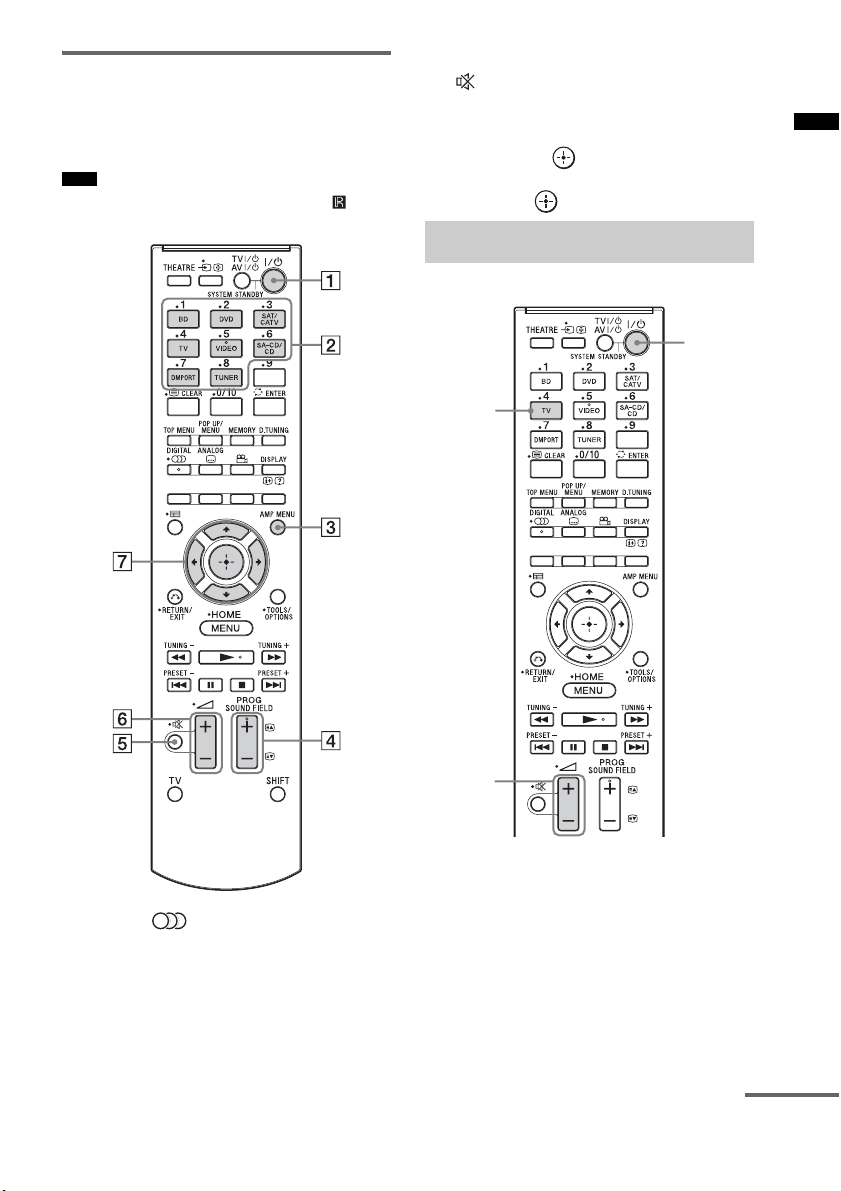
Remote control
This section describes subwoofer and speaker
button operation. See page 42 for details on the
button operation of connected components.
Note
• Point the r emote towards the remote senso r ( ) of the
subwoofer.
D SOUND FIELD +/– (page 36)
E (muting)
F
2 +/–
Press to adjust the volume.
G C, X, x, c or
Press C, X, x or c to select the menu items.
Then press to enter the selection.
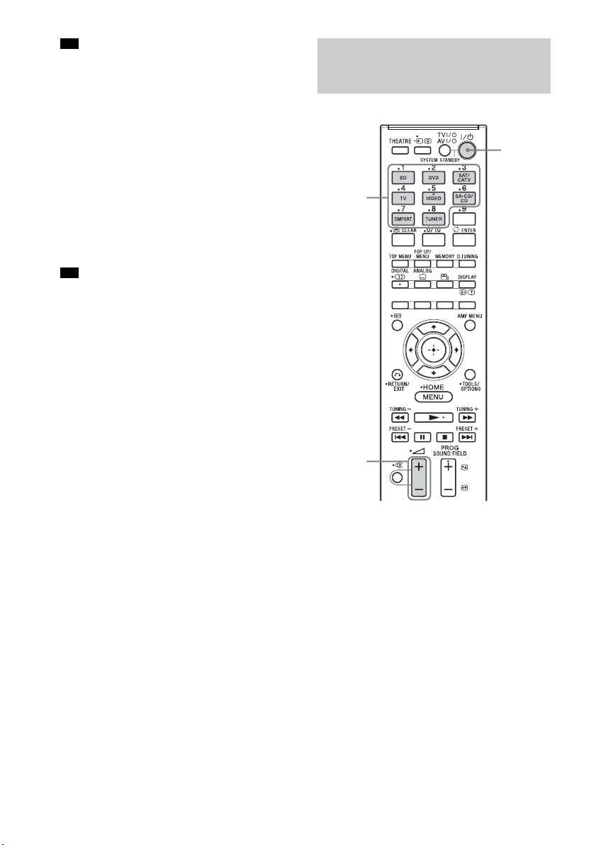
Enjoying TV
TV
Playback Options
?/1
* The 5, N, and SOUND FIELD + buttons
have a tactile dot. Use it as a guide during operation.
A ?/1 (on/standby)
B Input buttons
Press one of the buttons to select the
component you want to use.
C AMP MENU (page 47)
2 +/–
1 Turn on the TV and choose a program.
Refer to the operating instructions of your
TV for details.
2 Turn the system on.
3 Press TV on the remote.
4 Adjust the volume by pressing 2 +/–.
continued
29
GB
Tip
• The sound may be output from the TV’s speaker. In
this case, turn the volume of the TV’s speaker down
to minimum.
If you are using “BRAVIA” Sync
(System Audio Control)
You do not need to perform steps 2 and 3 above.
When you turn on the TV, the system is also
turned on, and the input source changes
automatically. You can also adjust the system’s
volume using the TV’s remote. If you turn off the
system, sound is output from the TV’s speaker.
For details on setting “BRAVIA” Sync, see
“Preparing for “BRAVIA” Sync” (page 37).
Tip
• The system is not turned on when you turn the TV on
if sound was being output from the TV speakers the
last time the TV was turned off.
Enjoying other
components
?/1
Input
buttons
30
2 +/–
1 Play the connected component.
2
Turn on the system.
GB
 Loading...