

Page 1

4-181-486-11(2)
Home Theatre System
HT-CT350
©2010 Sony Corporation
Operating Instructions
Mode d’emploi
Manual de instrucciones
US
FR
ES
Page 2
3
WARNING
To reduce the risk of fire or electric
shock, do not expose this apparatus to
rain or moisture.
The unit is not disconnected from the AC power source
(mains) as long as it is connected to the wall outlet,
even if the unit itself has been turned off.
To reduce the risk of fire, do not cover the ventilation
opening of the apparatus with newspapers, tablecloths,
curtains, etc.
Do not place the naked flame sources such as lighted
candles on the apparatus.
To reduce the risk of fire or electric shock, do not
expose this apparatus to dripping or splashing, and do
not place objects filled with liquids, such as vases, on
the apparatus.
As the main plug is used to disconnect the unit from the
mains, connect the unit to an easily accessible AC
outlet. Should you notice an abnormality in the unit,
disconnect the main plug from the AC outlet
immediately.
Do not install the appliance in a confined space, such as
a bookcase or built-in cabinet.
Do not expose batteries or apparatus with batteryinstalled to excessive heat such as sunshine, fire or the
like.
For the customers in the U.S.A
This symbol is intended to alert the user to
the presence of uninsulated “dangerous
voltage” within the product’s enclosure that
may be of sufficient magnitude to constitute a risk of
electric shock to persons.
This symbol is intended to alert the user to
the presence of important operating and
maintenance (servicing) instructions in the
literature accompanying the appliance.
Owner’s Record
The model and serial numbers are located at the rear of the
subwoofer. Record the serial numbers in the spaces
provided below. Refer to them whenever you call upon
your Sony dealer regarding this product.
Model No. HT-CT350
Serial No.
Important Safety Instructions
1) Read these instructions.
2) Keep these instructions.
3) Heed all warnings.
4) Follow all instructions.
5) Do not use this apparatus near water.
6) Clean only with dry cloth.
7) Do not block any ventilation openings. Install in
accordance with the manufacturer’s instructions.
8) Do not install near any heat sources such as
radiators, heat registers, stoves, or other apparatus
(including amplifiers) that produce heat.
9) Do not defeat the safety purpose of the polarized or
grounding-type plug. A polarized plug has two
blades with one wider than the other. A grounding
type plug has two blades and a third grounding
prong. The wide blade or the third prong are
provided for your safety. If the provided plug does
not fit into your outlet, consult an electrician for
replacement of the obsolete outlet.
10) Protect the power cord from being walked on or
pinched particularly at plugs, convenience
receptacles, and the point where they exit from the
apparatus.
11) Only use attachments/accessories specified by the
manufacturer.
12) Use only with the cart, stand, tripod, bracket, or
table specified by the manufacturer, or sold with the
apparatus. When a cart is used, use caution when
moving the cart/apparatus combination to avoid
injury from tip-over.
13) Unplug this apparatus during lightning storms or
when unused for long periods of time.
US
2
Page 3

14) Refer all servicing to qualified service personnel.
Servicing is required when the apparatus has been
damaged in any way, such as power-supply cord or
plug is damaged, liquid has been spilled or objects
have fallen into the apparatus, the apparatus has
been exposed to rain or moisture, does not operate
normally, or has been dropped.
The following FCC statement applies only to the
version of this model manufactured for sale in the
U.S.A. Other versions may not comply with FCC
technical regulations.
NOTE:
This equipment has been tested and found to comply
with the limits for a Class B digital device, pursuant to
Part 15 of the FCC Rules. These limits are designed to
provide reasonable protection against harmful
interference in a residential installation. This
equipment generates, uses, and can radiate radio
frequency energy and, if not installed and used in
accordance with the instructions, may cause harmful
interference to radio communications. However, there
is no guarantee that interference will not occur in a
particular installation. If this equipment does cause
harmful interference to radio or television reception,
which can be determined by turning the equipment off
and on, the user is encouraged to try to correct the
interference by one or more of the following measures:
– Reorient or relocate the receiving antenna.
– Increase the separation between the equipment and
receiver.
– Connect the equipment into an outlet on a circuit
different from that to which the receiver is
connected.
– Consult the dealer or an experienced radio/TV
technician for help.
CAUTION
You are cautioned that any changes or modifications
not expressly approved in this manual could void your
authority to operate this equipment.
Precautions
On safety
• Should any solid object or liquid fall into the system,
unplug the system and have it checked by qualified
personnel before operating it any further.
• Do not climb on the subwoofer, as you may fall down
and injure yourself, or system damage may result.
On power sources
• Before operating the system, check that the operating
voltage is identical to your local power supply. The
operating voltage is indicated on the nameplate at the
rear of the subwoofer.
• If you are not going to use the system for a long time,
be sure to disconnect the system from the wall outlet
(mains). To disconnect the AC power cord (mains
lead), grasp the plug itself; never pull the cord.
• One blade of the plug is wider than the other for the
purpose of safety and will fit into the wall outlet
(mains) only one way. If you are unable to insert the
plug fully into the outlet, contact your dealer.
• AC power cord (mains lead) must be changed only at
the qualified service shop.
On heat buildup
Although the system heats up during operation, this is
not a malfunction. If you continuously use this system
at a large volume, the system temperature of the back
and bottom rises considerably. To avoid burning
yourself, do not touch the system.
On placement
• Place the system in a location with adequate
ventilation to prevent heat buildup and prolong the
life of the system.
• Do not place the system near heat sources, or in a
place subject to direct sunlight, excessive dust, or
mechanical shock.
• Do not place anything at the rear of the subwoofer that
might block the ventilation holes and cause
malfunctions.
• Do not place the syst em near equipment such as a TV,
VCR, or tape deck. (If the system is being used in
combination with a TV, VCR, or tape deck, and is
placed too close to that equipment, noise may result,
and picture quality may suffer. This is especially
likely when using an indoor antenna. Therefore, we
recommend using an outdoor antenna.)
• Use caution when placing the system on surfaces that
have been specially treated (wi th wax, oil, polish, etc.)
as staining or discoloration of the surface may result.
US
continued
US
3
Page 4

On operation
Before connecting ot her components, be sure to turn of f
and unplug the system.
If you encounter color irregularity on
a nearby TV screen
The system is magnetically shielded to allow it to be
installed near a TV set. However, color irregularities
may still be observed on certain types of TV sets.
If color irregularity is observed...
Turn off the TV set, then turn it on again after 15 to 30
minutes.
If color irregularity is observed
again...
Place the system further away from the TV set.
On cleaning
Clean the system with a soft dry cloth. Do not use any
type of abrasive pad, scouring powder or solvent such
as alcohol or benzine.
If you have any question or problem concerning your
system, please consult your nearest Sony dealer.
Copyrights
This system incorporates Dolby* Digital and Pro Logic
Surround and the DTS** Digital Surround System.
*
Manufactured under license from Dolby Laboratories.
Dolby, Pro Logic, and the double-D symbol are
trademarks of Dolby Laboratories.
** Manufactured under license under U.S. Patent #'s:
5,451,942; 5,956,674; 5,974,380; 5,978,762;
6,487,535 & other U.S. and worldwide patents
issued & pending. DTS and the Symbol are
registered trademarks & DTS Digital Surround and
the DTS logos are trademarks of DTS, Inc. Product
includes software. © DTS, Inc. All Rights Reserved.
“x.v.Color” and “x.v.Color” logo are trademarks of
Sony Corporation.
®
ENERGY STAR
registered mark.
As an ENERGY STAR
Sony Corporation ha s determined that
this product meets the ENERGY
®
STAR
guidelines for energy
efficiency.
is a U.S.
®
partner,
This system incorporates High-Definition Multimedia
Interface (HDMI™) technology.
HDMI, the HDMI Logo, and High-Definition
Multimedia Interface are trademarks or registered
trademarks of HDMI Licensing LLC in the United
States and other countries.
“BRAVIA Sync” is a trademark of Sony Corporation.
“PlayStation” is a registered trademark of Sony
Computer Entertainment Inc.
US
4
Page 5

Table of contents
Precautions...............................................3
Getting Started
Unpacking................................................6
Positioning the system .............................8
Warning about installing the system’s
speaker to the TV stand or a wall ....10
Connecting the speaker ..........................22
Connecting the TV and player, etc. .......23
Connecting other components................25
Connecting the antenna (aerial) .............26
Connecting the AC power cord (mains
lead) .................................................27
Setting up the sound output of the
connected component......................27
Playback Options
Index to parts and controls.....................28
Enjoying TV...........................................30
Enjoying other components ...................31
Tuner Functions
Direct tuning ..........................................33
Presetting radio stations.........................34
Listening to the radio .............................34
Naming preset stations...........................35
Viewing the station name or frequency in
the front panel display .....................36
Surround Function
Enjoying the surround effect..................37
“BRAVIA” Sync Features
What is “BRAVIA” Sync?.....................38
Preparing for “BRAVIA” Sync .............38
Enjoying Blu-ray Disc/DVD..................39
(One-Touch Play)
Enjoying the TV sound from the
system ..............................................40
(System Audio Control)
Turning off the system, TV and the
connected components.....................41
(System Power Off)
Using the power saving function ...........41
(HDMI PASS THRU)
Setting the Audio Return Channel function
to off................................................ 42
Advanced Settings
Controlling connected Sony components
with the remote ............................... 43
Changing the input button assignments of
the remote........................................46
Settings and adjustments using the
amplifier menu................................ 48
Additional Information
Troubleshooting ....................................52
Specifications........................................ 54
Index...................................................... 57
US
5
Page 6
Getting Started
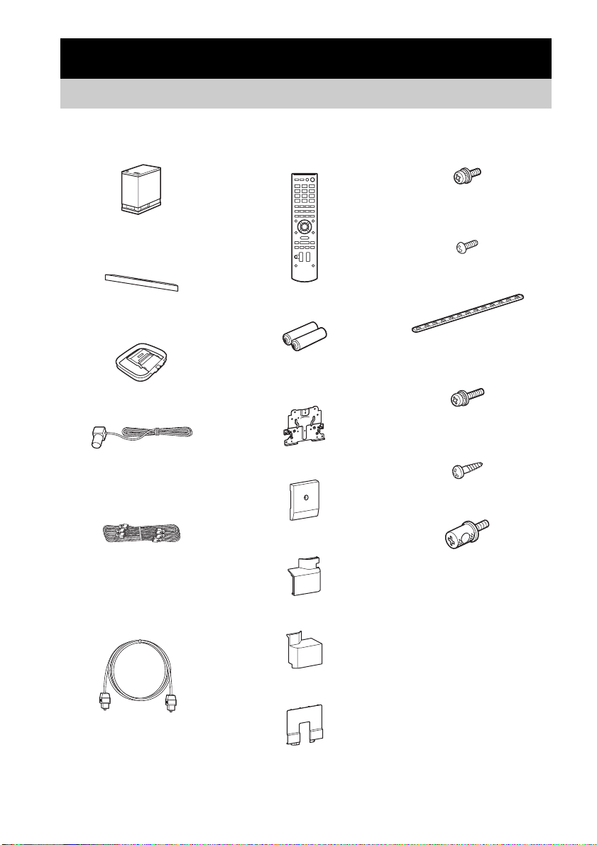
Unpacking
• Subwoofer (SA-WCT350) (1)
• Speaker (SS-CT350) (1)
• AM loop antenna (aerial) (1)
• FM wire antenna (aerial) (1)
• Speaker cord (1)
• Remote commander (RMAAU071) (1)
• R6 (size AA) batteries (2)
• WS-CT350EB
• Extension bracket (1)
• Rear cover A (1)
• Rear cover B (1)
• Screws for the extension bracket
(large, +PSW5 × 16 mm) (6)
• Screws for the rear cover (small,
M3 × 8 mm) (1)
• Support belt (1)
• Screw for the support belt
(+PSW4 × 20 mm) (1)
• Wood screw for the support belt
(M3.8 × 20 mm) (1)
• Clamp screw (2)
• Digital optical cord for a TV
(2.5 m) (1)
US
6
• Warranty (1)
• Operating Instructions (1)
• Rear cover C (1)
• Cover for the TV (1)
Page 7
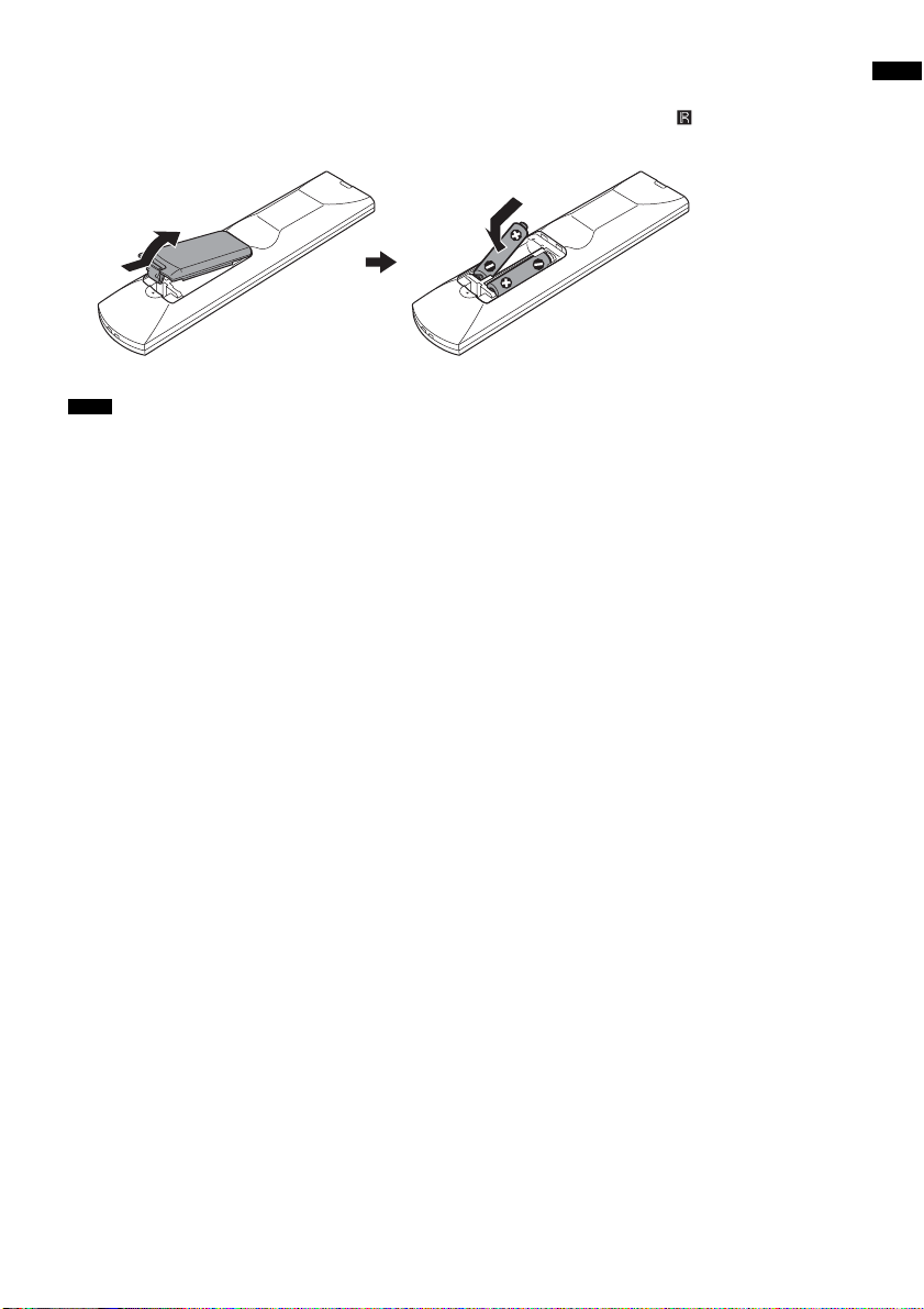
Inserting batteries into the remote
Insert two R6 (size AA) batteries (supplied) by matching the 3 and # ends on the batteries to the
markings inside the compartment. To use the remote, point it at the remote sensor in the front panel
display of the subwoofer.
Notes
• Do not leave the remote in an extremely hot or humid place.
• Do not use a new battery with an old one.
• Do not drop any foreign object into the remote casing, particularly when replacing the batteries.
• Do not expose the remote sensor to direct sunlight or lighting apparatus. Doing so may cause a malfunction.
• If you do not intend to use the remote for an extended period of time, remove the batteries to avoid possible damage
from battery leakage and corrosion.
Getting Started
US
7
Page 8
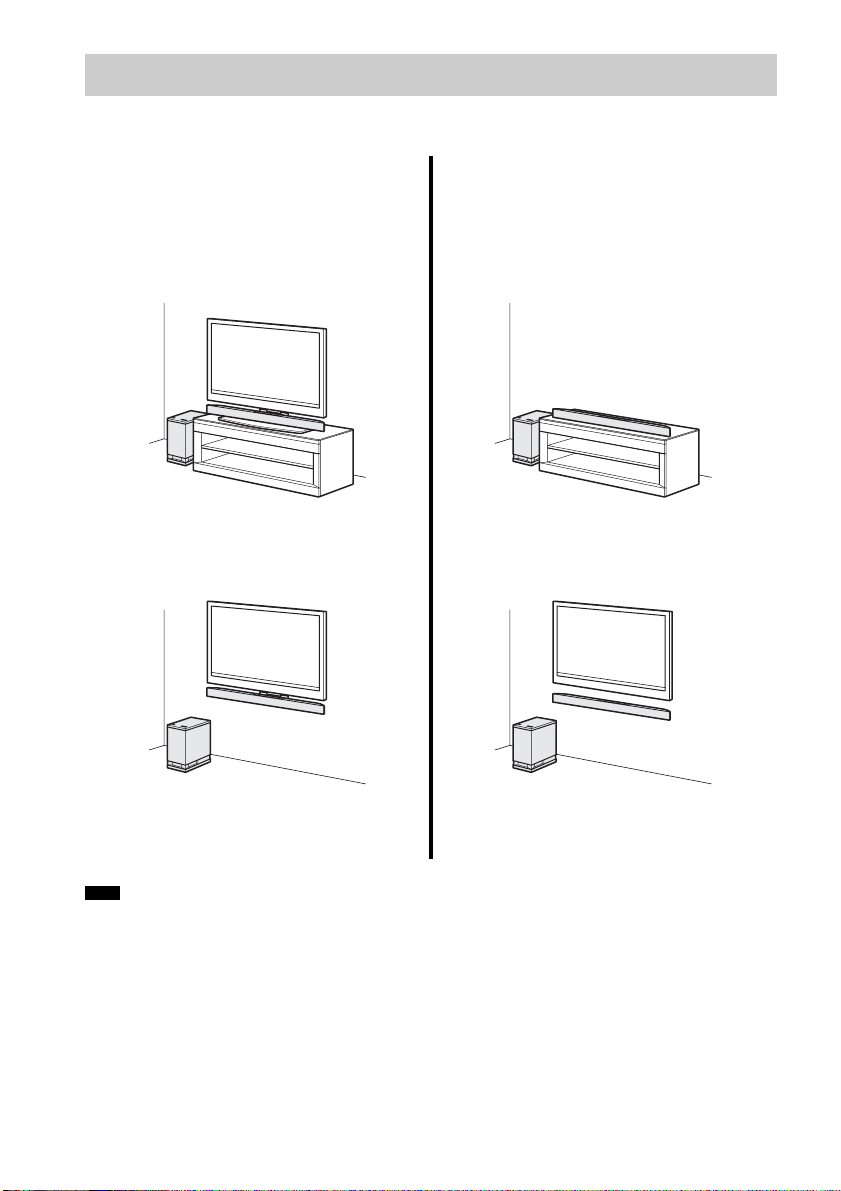
Positioning the system
The illustrations below are examples of how to install the subwoofer and speaker.
You can install the speaker with the following
TV models (not supplied):
• KDL-40/46LX900, KDL-40NX800,
KDL-40/46HX800, KDL-40/46EX700,
KDL-46EX701, KDL-40/46NX700,
KDL-40/46EX600
For details, see “Installing the speaker on
the TV stand” (page 13).
For details, see “H anging the speaker and
TV on a wall” (page 17).
Note
• Do not block the heat ventilation on the rear panel of the subwoofer.
For details, see “Installing the speaker on
a wall” (page 21).
Install the speaker on a rack.
US
8
Page 9
Connecting the speaker cord to the speaker
The connectors of the speaker cord are color-coded depending on the type of speaker. Connect the
connectors of the speaker cord to match the color of the speaker jacks.
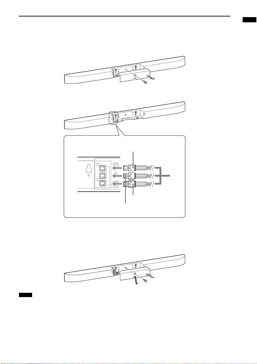
1 Remove the screw of the cover at the rear of the speaker, and then remove the cover.
2 Connect the speaker cord.
Getting Started
Green
White
A
Red
A Speaker cord
(supplied)
Rear of the speaker
R CENTER L
3 Guide the speaker cord through the square notch at the bottom of the cover, and then
reattach the cover to the speaker and secure it with the screw removed in step 1.
If you install the speaker to the TV, do not reattach the cover. Perform the steps in “Installing the
speaker on the TV stand” (page 13), or “Hanging the speaker and TV on a wall” (page 17).
Notes
• When you install the speaker or a TV on a wall, be careful not to stumble over the cord connected to the speaker.
• Be careful not to pinch the speaker cord when you reattach the cover.
US
9
Page 10
Warning about installing the system’s speaker to the TV
stand or a wall
To Customers
Sufficient expertise is required for installing this
product. Be sure to subcontract the installation to
Sony dealers or licensed contractors and pay
special attention to safety during the installation.
Sony is not liable for any damages or injury
caused by mishandling or improper installation,
or installing anything other than the specified
product. Your statutory rights (if any) are not
affected.
On Safety
Products by Sony are designed with safety in
mind. If the products are used incorrectly,
however, it may result in a serious injury through
fire, electric shock, the product toppling over, or
the product dropping. Be sure to observe the
precautions for safety to prevent such accidents.
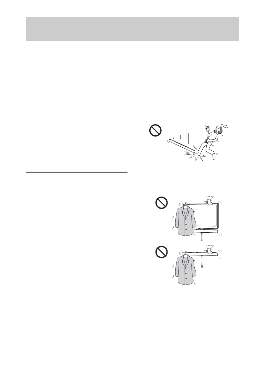
WARNING
If the following precautions are not observed,
serious injury or death through fire or electric
shock, the product toppling over or falling can
result.
Do not drop the products or install them
where there is a possibility of them falling
down.
• Be sure to subcontract installing, moving or
dismounting the products to licensed
contractors and keep small children away
during the procedure.
• Unauthorized installation may result in serious
injury or property damage.
• Having an unauthorized dealer carry or
dismount the SS-CT350 speaker or SS-CT350
speaker-installed TV may lead to the products’
falling and result in serious injury or property
damage. Make sure that two or more persons
carry or dismount the product(s).
• Do not remove screws, etc., after mounting the
SS-CT350 speaker or SS-CT350 speakerinstalled TV.
• Do not handle the products with excessive
force during cleaning or maintenance.
• If you hang the SS-CT350 speaker or SSCT350 speaker-installed TV on a fragile wall
or a wall whose surface is not flat or
perpendicular, the product(s) may fall and
cause injury or property damage.
• If the SS-CT350 speaker or SS-CT350
speaker-installed TV is not installed firmly on
the wall, the product(s) may fall and cause
injury or property damage.
Do not place any object on the products.
• Do not put anything on the products. If you do
so, the system may fall and cause injury or
property damage.
10
US
Page 11
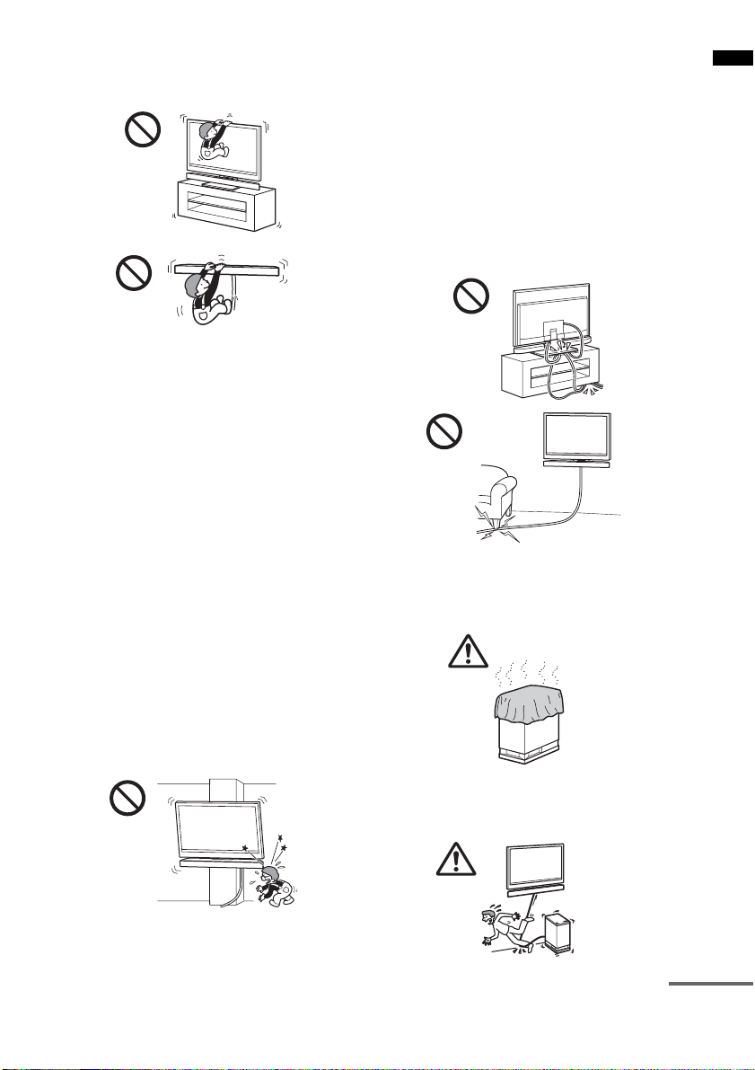
Do not lean or hang on the products.
• Do not lean or hang on the products, as they
may fall on you and cause serious injury.
Pay attention to the location.
• Do not install the products on wall surfaces
such as a pillar, where the corners or the sides
of the products protrude away from the wall
surface. If a person or object happens to hit the
protruded corner or side of the products, it may
cause injury or property damage.
• Do not expose the products to rain or moisture,
or spill liquid of any kind on them. It may cause
a fire or electric shock.
• Never place the products in hot, humid or
excessively dusty places, or in a place where
they are subject to mechanical vibrations.
Doing so may cause a fire or electric shock.
• Keep flammable objects or open flames (e.g.,
candles) away from the products.
• Do not install the products over or under an airconditioner. If the products are exposed to
wind from the air conditioner for an extended
period of time, or get wet by water leakage
from the air conditioner, this may cause a fire,
an electric shock, or malfunctions.
Do not allow the cords to be pinched.
• If the AC power cord (mains lead) or
connecting cords are pinched between the
products and the wall, floor, or other object, or
bent or twisted by force, the internal
conductors may become exposed and cause a
short circuit or an electrical break. This may
cause a fire or an electric shock.
• Do not step on the AC power cord (mains lead)
or connecting cords when you carry the
products. The cord may be damaged, and this
may result in a fire or electric shock.
Do not cover the ventilation holes of the
products.
• If you cover the ventilation holes (with a cloth,
etc.), heat may build up inside and cause a fire.
Do not stumble over the cords.
• You may trip, or may cause the products to
topple over and cause injury.
Getting Started
continued
11
US
Page 12
CAUTION
If the following precautions are not observed,
injury or property damage may occur.
Do not install any equipment other than the
specified product.
• The WS-CT350EB accessories (supplied) are
designed for use with the specified equipment
only. If you install equipment other than that
specified, it may fall or break, and cause injury.
• Do not modify the products.
• Do not place anything hot directly on the
products. The heat may cause discoloration or
deformation of the products.
Be sure to secure the system’s speaker and
TV.
• Secure the SS-CT350 speaker and TV firmly
when installing them together. Then, secure the
SS-CT350 speaker-installed TV firmly on the
stand or wall. If the SS-CT350 speaker and TV
are not installed securely, they may fall or
topple over, and cause injury.
Do not apply weight to the products or
subject them to any kind of impact.
• When installing the SS-CT350 speaker to a TV
stand or hanging the SS-CT350 speaker installed TV on a wall, do not apply weight to
the speaker or TV with your hand. Do not hit
the speaker or TV with hard objects, such as a
screwdriver, etc.
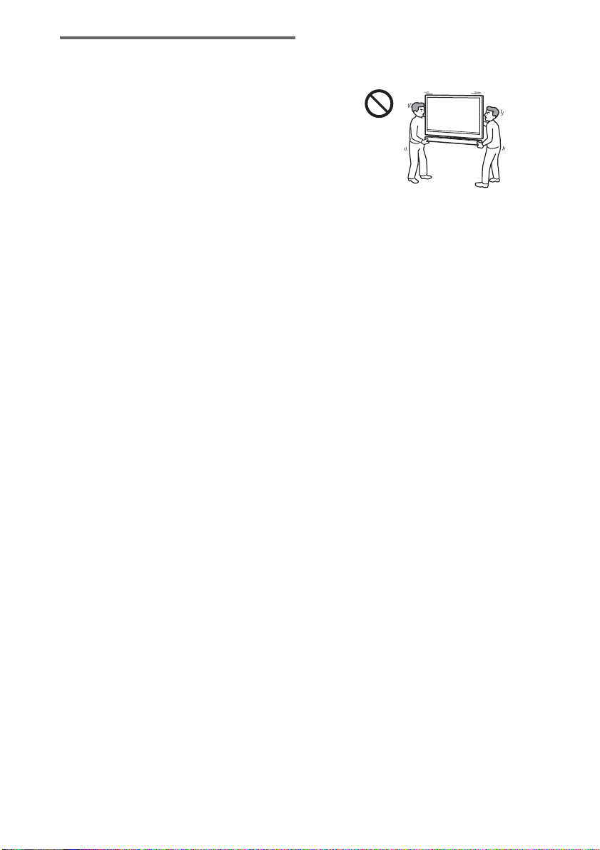
When moving the SS-CT350 speakerinstalled TV
If you move the products forcefully, damage or
injury may result. Be sure to follow the proper
procedures and advice given below.
• Be sure that two or more persons carry the SSCT350 speaker-installed TV, and only after
unplugging and removing the connected
equipment.
• Be careful not to allow your hands or feet to be
pinched under the bottom of the SS-CT350
speaker-installed TV.
• When carrying the SS-CT350 speakerinstalled TV, do not hold it by the SS-CT350
speaker part. Doing so may cause damage or
injury.
• Do not drag the SS-CT350 speaker-installed
TV. The base part may come off and damage
the floor.
Notes on installation
• When assembling, spread a cloth on the floor to
avoid damaging the floor.
• Install the products on a solid and flat floor.
• Be sure that two or more persons install the
products. Doing it alone may result in an
accident or injury.
• Be sure to keep children away during the
process.
Be sure to install the products securely
following the instructions.
• Tighten the screws securely. If the SS-CT350
speaker is not installed securely, it may fall and
cause damage or injury.
• Be careful not to pinch your fingers or hands
when assembling the products.
Notes on installation on a wall
• If you use the products installed on a wall for a
long time, the wall behind or above the
products may become discolored or the
wallpaper may come unstuck, depending on
the material of the wall.
• If the products are removed after installed on
the wall, the screw holes will remain.
• Consult your licensed contractor regarding an
appropriate location (free from radio noise,
etc.) before installing.
12
US
Page 13
Installing the speaker on the TV stand
You can install the speaker with the following TV models (not supplied):
• KDL-40/46LX900, KDL-40NX800, KDL-40/46HX800, KDL-40/46EX700, KDL-46EX701,
KDL-40/46NX700, KDL-40/46EX600
Although the shape of the TV stand base differs depending on the TV model, you can install the speaker
on the TV stand following this procedure.
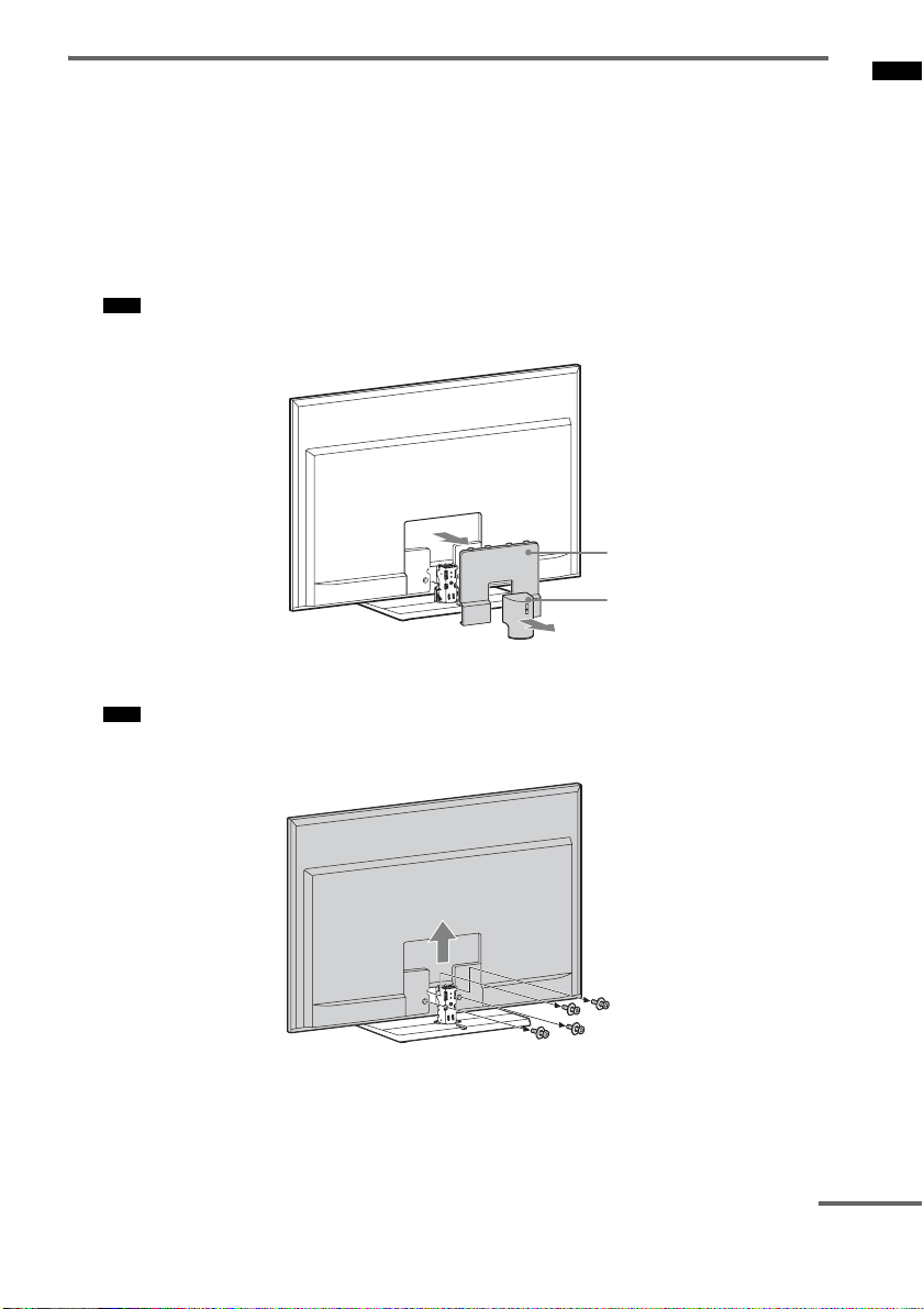
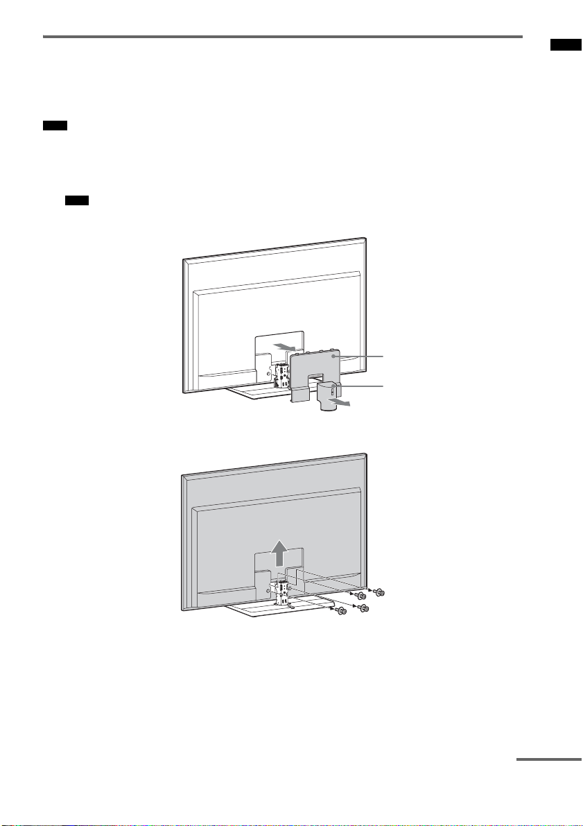
1 Remove covers 1 and 2 from the rear of the TV.
For details on removing the covers, refer to the operating instructions of the TV.
Note
• Some Sony TVs do not have cover 2.
Cover 2
Cover 1
2 Remove the screws of the TV, and then detach the TV from the TV stand.
Note
• Make sure to place the TV on a soft thick cloth with the screen side down to prevent damaging the surface of
the LCD.
Getting Started
continued
13
US
Page 14
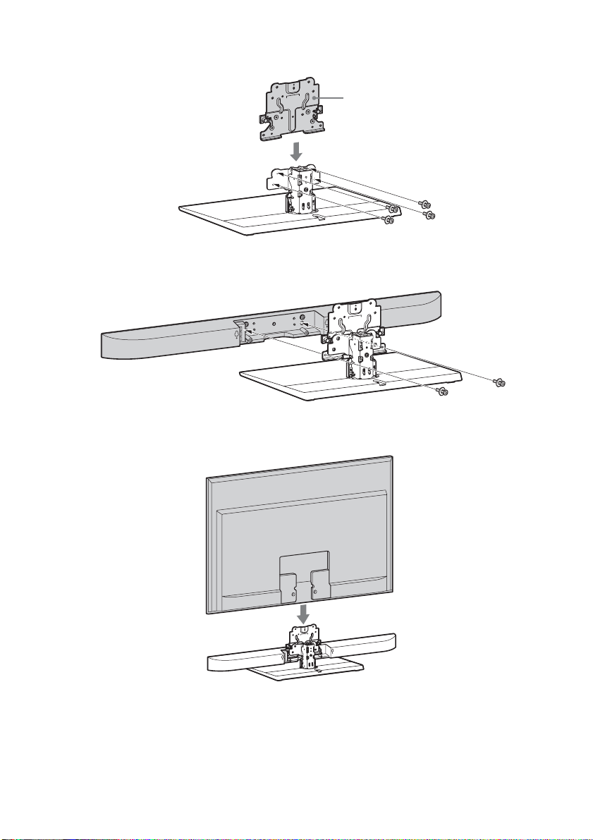
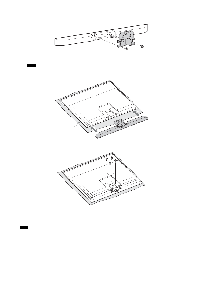
3 Secure the extension bracket (supplied) to the TV stand with the large screws (+PSW5
× 16 mm) (supplied).
Extension bracket
4 Secure the speaker to the extension bracket with the large screws (+PSW5 × 16 mm)
(supplied).
5 Reattach the TV.
14
US
Page 15
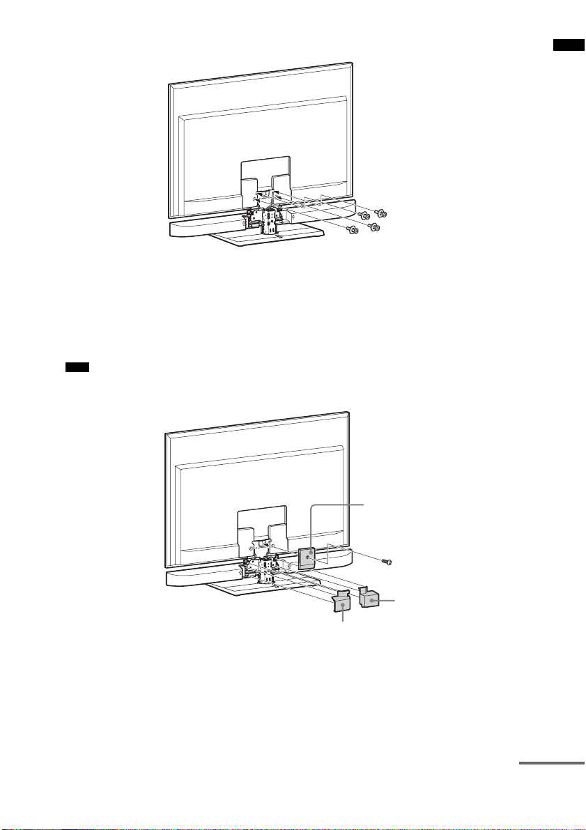
6 Secure the TV with the screws removed in step 2.
7 Attach the rear covers A, B, and C (supplied).
Secure the rear cover A to the extension bracket with the small screw (M3 × 8 mm) (supplied).
Guide the speaker cord through the rectangular notch of the rear cover B, and insert the three
projecting parts of the rear cover B into the holes on the extension bracket and the speaker.
Insert the three projecting parts of the rear cover C into the holes on the extension bracket and the
speaker.
Note
• When carrying the SS-CT350 speaker-installed TV, do not hold it by the SS-CT350 speaker part. Doing so
may cause damage or injury.
Getting Started
Rear cover A
Rear cover B
Rear cover C
continued
15
US
Page 16
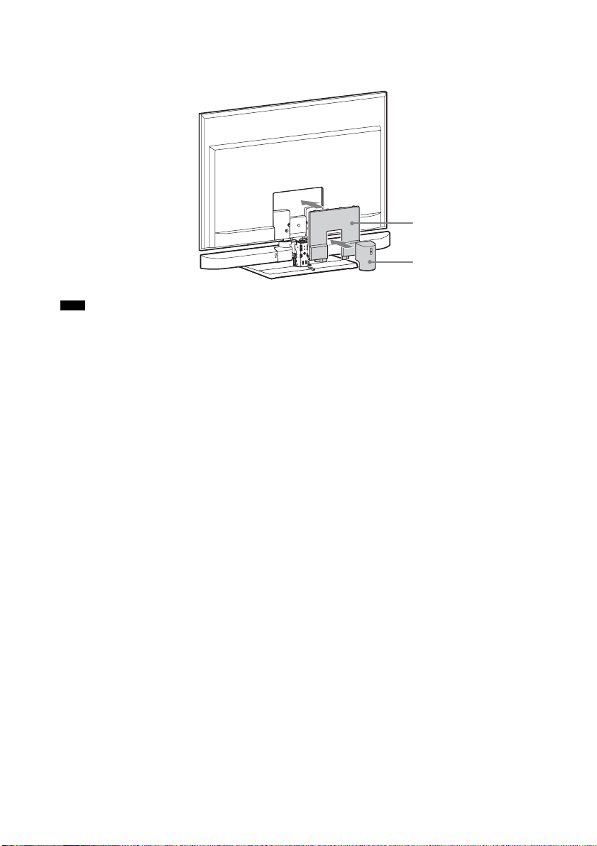
8 Attach the cover for the TV (supplied) and cover 1 removed in step 1.
Insert the two projecting parts of the cover for the TV into the holes on the TV.
For details on attaching cover 1, refer to the operating instructions of the TV.
Cover for the TV
Cover 1
Note
• As a protective measure, secure the TV. For details, see “Preventing the TV from toppling over” (page 19).
16
US
Page 17
Hanging the speaker and TV on a wall
You can hang the speaker with the following TV models (not supplied):
• KDL-40/46LX900, KDL-40NX800, KDL-40/46HX800, KDL-40/46EX700, KDL-46EX701,
KDL-40/46NX700, KDL-40/46EX600
Note
• To hang the TV on the wall, refer to the operating instructions of the TV.
1 Remove covers 1 and 2 from the rear of the TV.
For details on removing the covers, refer to the operating instructions of the TV.
Note
• Some Sony TVs do not have cover 2.
Cover 2
Cover 1
2 Remove the screws of the TV, and then detach the TV from the TV stand.
Getting Started
continued
17
US
Page 18
3 Secure the speaker to the extension bracket with the large screws (+PSW5 × 16 mm)
(supplied).
4 Reattach the TV.
Note
• Make sure to place the TV on a soft thick cloth with the screen side down to prevent damaging the surface of
the LCD.
Cloth
5 Secure the TV with the screws removed in step 2.
6 Hang the TV on the wall.
For details on hanging the TV on the wall, refer to the operating instructions of the TV.
Note
• When hanging the SS-CT350 speaker-installed TV on the wall or taking it off the wall, do not hold it by the SSCT350 speaker part. Doing so may cause damage or injury.
US
18
Page 19

Preventing the TV from toppling over
As a protective measure, secure the TV. If you fail to do so, the TV may topple over resulting in serious
injury.
When installing the TV on a rack
Screw for the support belt
(+PSW4 × 20 mm)
Wood screw for the support belt
(M3.8 × 20 mm)
1 Place the TV on the center of the rack.
2 Fit the support belt (supplied) to the TV, then firmly fasten with the screw for the support
belt (+PSW4 × 20 mm) (supplied) using a screw driver.
3 Fasten the support belt to the rack with the wood screw for the support belt (M3.8 × 20
mm) (supplied).
Notes
• Be careful not to pinch your fingers when setting up the TV and rack.
• Install the rack after allowing for a space of less than 25 cm (9 7/8 inches) from the wall. The wall will prevent the
TV from falling from the rack even if the TV leans backward towards the wall.
Side view
Less than
25 cm
(9 7/8 inches)
Getting Started
continued
19
US
Page 20

When installing the TV on the floor near a wall
Prepare strong string or chain (not supplied) and a fastener (not supplied) for fastening to the wall.
Secure the fastener to a reinforced wall.
1 Fasten the clamp screws (supplied) to the rear of the TV.
Clamp screw
2 Secure the fastener to the wall (1), and then thread the string or chain through the holes
of the clamp screws and the fastener (2). Firmly tie both ends of the string or chain
together.
1
20
2
US
Page 21

Installing the speaker on a wall
You can install the speaker on the wall.
Notes
• Use screws that are suitable for the wall material and strength. As a plaster board wall is especially fragile, attach
the screws securely to a wall beam. Install the speaker on a vertical and flat reinforced area of the wall.
• Be sure to subcontract the installation to Sony dealers or licensed contractors and pay special attention to safety
during the installation.
• Sony is not responsible for accidents or damage caused by improper installation, insufficient wall strength,
improper screw installation or natural calamity, etc.
1 Prepare screws (not supplied) that are suitable for the holes on the back of the speaker.
See the illustrations below.
4 mm (1/6 inches)
more than 25 mm (1 inch)
5mm
(1/5 inches)
10 mm
(2/5 inches)
Hole on the back of the speaker
2 Fasten the screws to the wall. The screws should protrude 6 to 7 mm (approx. 1/4
inches).
265 mm
(10 2/5 inches)
Getting Started
6 to 7 mm
(approx. 1/4 inches)
3 Hang the speaker onto the screws.
Align the holes on the back of the speaker to the screws, then hang the speaker onto the two screws.
21
US
Page 22

Connecting the speaker
The connectors of the speaker cord are color-coded depending on the type of speaker. Connect the
connectors of the speaker cord to match the color of the SPEAKERS jacks.
Rear of the
subwoofer
DMPORT
DC 5V
0.7A MAX
Green
Red White
Speaker
L
ONLY FOR
SS-CT350
A
AUDIO I N
SA-CD/CD
SAT/CATV INBD INDVD IN
HDMI
L
R
AUDIO I N
ANTENNA
FM
75 COAXIAL
OPT IN
TV OUT
TVSAT/CATVR CENTER
AM
ARC
COAX IN
VIDEO
TV
DIGITALSPEAKERS
22
A Speaker cord (supplied)
US
Page 23

Connecting the TV and player, etc.
Connect the TV and/or player, etc., with HDMI jacks to the system using an HDMI cable.
By connecting Sony “BRAVIA” Sync-compatible components using HDMI cables and by setting the
Control for HDMI function via the TV for each connected component, operation can be simplified. See
““BRAVIA” Sync Features” (page 38).
DVD player, etc.
HDMI OUT
HDMI cable
(not supplied)
HDMI cable
(not supplied)
TV
HDMI IN
Getting Started
Rear of the
subwoofer
Blu-ray Disc player, etc.
HDMI OUT
DMPORT
DC 5V
0.7A MAX
L
HDMI cable
(not supplied)
ONLY FOR
SS-CT350
AUDIO I N
SA-CD/CD
SAT/CATV INBD INDVD I N
L
ANTENNA
R
AUDIO I N
75 COAXIAL
TV
HDMI
DIGITALSPEAKERS
OPT IN
Digital optical cord
(not supplied)
FM
TV OUT
TVSAT/CATVR CENTER
AM
ARC
COAX IN
VIDEO
HDMI cable
(not supplied)
Digital Audio OUT
(optical)
Digital optical cord fo r a TV
(supplied)
Satellite tuner or cable television
tuner, etc., with an HDMI jack
Digital Audio OUT
(optical)
HDMI OUT
continued
23
US
Page 24

Notes
• The system is compatible with the Audio Return Channel (ARC) function. If you connect the system to the ARCcompatible TV’s HDMI jack via an HDMI cable, you do not need to connect the TV to the system with the digital
optical cord (page 42).
• You can see the letters “ARC” beside the TV’s HDMI jack if it is compatible with the ARC function. Even if you
connect an HDMI cable to the jack, if the HDMI input jack is not compatible with the ARC function, you cannot
use the ARC function.
• The ARC function is available only when Control for HDMI is set to on.
• Depending on the satellite tuner, multi-channel sound may not be output. In this case, connect a digital optical cord
in addition to an HDMI cable and set “INPUT MODE” to “OPT” in the AMP menu (page 50).
• Connect a “ PlayStation 3,” etc., to any availabl e HDMI jack. All the HDMI jacks on the system functio n in the same
way.
• The HDMI jack connections have priority when you connect different components to the system using the INPUT
OPT/INPUT COAX and HDMI jacks.
• When connecting a TV that does not have a digital optical audio output jack, connect the TV to the system using
an analog audio cord (not supplied).
Tip
• Even if the system is turned off (active standby mode), the HDMI signal will be sent from the con nected component
to the TV via the HDMI connection. You can enjoy image and sound from the component on the TV.
Notes on HDMI connections
• Use a High Speed HDMI cable. If you use a Standard HDMI cable, 1080p, Deep Color, or 3D images
may not be displayed properly.
• Sony recommends that you use an HDMI-authorized cable or Sony HDMI cable.
• Check the setup of the connected component if an image is poor or the sound does not come out of a
component connected via the HDMI cable.
• Audio signals (sampling frequency, bit length, etc.) transmitted from an HDMI jack may be
suppressed by the connected component.
• Sound may be interrupted when the sampling frequency or the number of channels of audio output
signals from the playback component is switched.
• When the connected component is not compatible with copyright protection technology (HDCP), the
image and/or the sound from the HDMI TV OUT jack may be distorted or may not be output.
In this case, check the specification of the connected component.
• We do not recommend using an HDMI-DVI conversion cable.
• When “TV,” “DMPORT,” “SA-CD/CD,” “VIDEO,” “TUNER FM,” or “TUNER AM” is selected
for the input source of the system, video signals via the HDMI input jack (BD, DVD, SAT/CATV)
that was selected last time are output from the HDMI TV OUT jack.
• This system supports Deep Color, “x.v.Color,” and 3D transmission.
• To enjoy 3D images, connect 3D-compatible TV and video components (Blu-ray Disc player, Blu-
ray Disc recorder, “PlayStation 3,” etc.) to the system using High Speed HDMI cables, put on 3D
glasses, and then play back 3D-compatible content.
24
US
Page 25

Connecting other components
When connecting components that do not have HDMI jacks, such as a “PlayStation 2,” a DVD player,
a satellite tuner, or a cable television tuner, etc., set “CTRL HDMI” to “OFF” in the AMP menu of the
system (page 39).
Other audio components, etc.
DVD player, etc.
Getting Started
Audio cord
(not supplied)
Digital coaxial cord
(not supplied)
Digital Audio OUT
(coaxial)
Audio signal OUT
VIDEO OUT
To the VIDEO IN of
the TV.
Rear of the
DIGITAL MEDIA
PORT adapter
Notes
subwoofer
DMPORT
DC 5V
0.7A MAX
L
ONLY FOR
SS-CT350
AUDIO I N
SA-CD/CD
SAT/CATV INBD INDVD IN
HDMI
L
R
AUDIO I N
TV
ANTENNA
FM
75 COAXIAL
AM
ARC
TV OUT
DIGITALSPEAKERS
COAX IN
OPT IN
TVSAT/CATVR CENTER
VIDEO
Digital optical cord
(not supplied)
Satellite tuner or cable
television tuner, etc.,
without an HDMI jack
Digital Audio OUT
(optical)
VIDEO OUT
To the VIDEO IN of the TV.
• Do not connect or disconnect the DIGITAL MEDIA PORT adapter while the system is turned on.
• When you connect the DIGITAL MEDIA PORT adapter, be sure the connector is inserted with the arrow mark
facing toward the arrow mark on the DMPORT jack. To detach the DIGITAL MEDIA PORT adapter, press and
hold A and then pull out the connector.
A
US
25
Page 26

Connecting the antenna (aerial)
Connecting the AM loop antenna (aerial)
The shape and the length of the antenna (aerial) is designed to receive AM signals. Do not dismantle
or roll up the antenna (aerial).
1 Remove only the loop part from the plastic stand.
2 Set up the AM loop antenna (aerial).
3 Connect the cords to the AM antenna (aerial) terminals.
While pushing down the terminal clamp, insert the (*) part of the cords.
The cords can be connected to either terminal.
Rear of the
subwoofer
ONLY FOR
SS-CT350
AUDIO I N
SA-CD/CD
SAT/CATV INBD IN
HDMI
L
R
AUDIO I N
TV
ANTENNA
FM
75 COAXIAL
DIGITAL
OPT IN
TV OUT
TVSAT/CATV
*
AM
ARC
COAX IN
VIDEO
Note
• Do not place the AM loop antenna (aerial) near the system or other AV component, as noise may result.
Tip
• Adjust the direction of the AM loop antenna (aerial) for best AM broadcast sound.
4 Make sure the AM loop antenna (aerial) is connected firmly by pulling softly on the cord.
US
26
Page 27

Connecting the FM wire antenna (aerial)
Connect the FM wire antenna (aerial) to the FM 75 Ω COAXIAL jack.
Rear of the
subwoofer
Notes
ONLY FOR
SS-CT350
AUDIO I N
SA-CD/CD
SAT/CATV INBD IN
HDMI
L
ANTENNA
R
FM
AUDIO I N
75 COAXIAL
OPT IN
TV OUT
TVSAT/CATV
AM
ARC
FM wire antenna
COAX IN
VIDEO
(aerial)
(supplied)
TV
DIGITAL
• Be sure to fully extend the FM wire antenna (aerial).
• After connecting the FM wire antenna (aerial), keep it as horizontal as possible.
• Do not use the FM wire antenna (aerial) while it is bundled up.
• Insert the FM wire antenna (aerial) fully and firmly to the terminal.
Tip
• If you have poor FM reception, use a 75-ohm coaxial cable (not supplied) to connect the subwoofer to an outdoor
FM antenna (aerial) as shown below.
FM 75 Ω COAXIAL jack
Getting Started
Rear of the
ANTENNA
subwoofer
FM
75 COAXIAL
Outdoor FM antenna
AM
(aerial)
Connecting the AC power cord (mains lead)
Before connecting the AC power cord (mains lead) of the system to a wall outlet (mains), connect all
the other components and TV to the system.
Notes
• After connecting the AC power cord (mains lead), wait about 20 seconds before turning on the power by pressing
?/1.
• Connect the system to an easily accessible AC outlet (mains). Should you notice an abnormality in the system,
disconnect the main plug from the AC outlet (mains) immediately.
Setting up the sound output of the connected component
To enjoy sound in multi-channel format (DTS, Dolby Digital, multi-channel LPCM), you need to make
the audio output settings of the connected component. Set the connected component to output sound in
multi-channel format. For details on audio output settings, refer to the operating instructions supplied
with the connected component.
27
US
Page 28

Playback Options
Index to parts and controls
For more information, see the pages indicated in parentheses.
Subwoofer
Top view
POWER/
ACTIVE STANDBY
INPUT
SELECTOR
VOLUME VOLUME
A ?/1 (on/standby)
B INPUT SELECTOR
Press to select the input source to play back.
Every time you press the button, the input
source changes cyclically as follows: TV t
BD t DVD t SAT/CATV t VIDEO
t SA-CD/CD t TUNER FM t TUNER
AM t DMPORT t TV……
US
28
C VOLUME –
D VOLUME +
E Front panel display
Page 29

Front panel display (subwoofer)
POWER/
ACTIVE STANDBY
Playback Options
A POWER/ACTIVE STANDBY indicator
Lights as follows:
Green: The system is turned on.
Amber: Only HDMI parts of the system
are on (The Control for HDMI
function is working).
No light: The system is turned off.
Note
• The amber light turns off 30 seconds after you
turn off the TV. However, if you set “PASS
THRU” to “ON” in the AMP menu, the indicator
stays amber even if you turn off the TV.
B Audio format indicators
Light up according to the audio format that
is being input to the system.
D: Dolby Digital
PLII: Dolby Pro Logic II
LPCM: Linear PCM
DTS
C NIGHT (page 50)
Lights up in NIGHT MODE.
D SLEEP (page 51)
Flashes when the sleep timer is active.
E HDMI (page 23)
Lights up when HDMI components are
being used or when an ARC signal is being
input to the system while TV is selected as
the input source.
F COAX/OPT
Light up according to the cable which you
are using.
G TUNED (page 34)
Lights up when tuned to a station.
H ST (page 34)
Lights up when a stereo program is
received.
I MUTING
Lights up when the sound is turned off.
J Remote sensor
K Message display area
Displays volume, selected input source,
audio input signal, etc.
continued
29
US
Page 30

Remote control
This section describes subwoofer and speaker
button operation. See page 43 for details on the
button operation of connected components.
Note
• Point the remote towards the remote sensor ( ) of the
subwoofer.
D SOUND FIELD +/– (page 37)
E MUTING
F MASTER VOL +/–
Press to adjust the volume.
G C, X, x, c or
Press C, X, x or c to select the menu items.
Then press to enter the selection.
Enjoying TV
?/1
TV
* The 5, N, AUDIO and SOUND FIELD + buttons
have a tactile dot. Use it as a guide during operation.
A ?/1 (on/standby)
B Input buttons
Press one of the buttons to select the
component you want to use.
C AMP MENU (page 48)
US
30
MASTER
VOL +/–
1 Turn on the TV and choose a program.
Refer to the operating instructions of your
TV for details.
2 Turn the system on.
3 Press TV on the remote.
4 Adjust the volume by pressing
MASTER VOL +/–.
Page 31

Tip
• The sound may be output from the TV’s speaker. In
this case, turn the volume of the TV’s speaker down
to minimum.
If you are using “BRAVIA” Sync
(System Audio Control)
You do not need to perform steps 2 and 3 above.
When you turn on the TV, the system is also
turned on, and the input source changes
automatically. You can also adjust the system’s
volume using the TV’s remote. If you turn off the
system, sound is output from the TV’s speaker.
For details on setting “BRAVIA” Sync, see
“Preparing for “BRAVIA” Sync” (page 38).
Tip
• The system is not turned on when you turn the TV on
if sound was being output from the TV speakers the
last time the TV was turned off.
Enjoying other
components
Playback Options
?/1
Input
buttons
MASTER
VOL +/–
1 Play the connected component.
2
Turn on the system.
continued
31
US
Page 32

3 Press the input buttons to display the
input source in the front panel display.
Input source Playable component
TV TV, etc. connected to the TV
jack
BD Blu-ray Disc player, etc.
connected to the BD jack
DVD DVD player, etc. connected to
the DVD jack
SAT/CATV Satellite tuner or cable
television tuner, etc. connected
to the SAT/CATV jack
VIDEO DVD player, etc. connected to
the DIGITAL COAX IN
VIDEO jack
SA-CD/CD CD player, et c. connected to the
SA-CD/CD AUDIO IN jack
TUNER FM* The built-in FM radio
TUNER AM* The built-in AM radio
DMPORT Portable audio player, etc.
connected to the DMPORT jack
* Press TUNER repeatedly to switch between
TUNER FM and TUNER AM.
4 For video components, change the TV’s
input to the HDMI input you chose in
step 3.
For details, refer to the operating
instructions of your TV.
5 Adjust the volume by pressing
MASTER VOL +/–.
Tips
• The sound may be output from the TV’s speaker. In
this case, turn the volume of the TV’s speaker down
to minimum.
• Even if you playback Dolby True HD, Dolby Digital
Plus or DTS HD with a connected component
compatible with these sound formats, the system
accepts the signal as Dolby Digital or DTS. When you
playback these high-quality sound formats, set the
connected component to output the sound in multichannel PCM, if possible.
Notes
• When you connect the video output jack of the
DIGITAL MEDIA PORT adapter to the video input
jack of the TV, set “CTRL HDMI” to “OFF” in the
AMP menu of the system (page 39). The images of a
component connected to the DIGITAL MEDIA
PORT adapter will not be played on the TV if “CTRL
HDMI” is set to “ON.”
• To enjoy the sound of a component without
displaying the images when “CTRL HDMI” is set to
“ON,” turn off the TV first and then reset the power of
the system.
If you turn on the system first and then turn off the
TV, all components connected to the TV will be
turned off because of the Control for HDMI function.
If you are using “BRAVIA” Sync
(One-Touch Play)
You do not need to perform steps 2 to 4 above.
When you turn on the connected components,
the system and the TV are also turned on, and the
input source changes automatically. You can
also adjust the system’s volume using the TV’s
remote.
For details on setting “BRAVIA” Sync, see
“Preparing for “BRAVIA” Sync” (page 38).
Tip
• The system is not turned on when you turn the TV on
if sound was being output from the TV speakers the
last time the TV was turned off.
32
US
Page 33

Tuner Functions
Direct tuning
You can enter the frequency of a station directly
using the number buttons.
3 While pressing and holding SHIFT (1),
press the number buttons (2) to enter
the frequency.
Example: 88.00 MHz
While pressing and holding SHIFT, select 8
t 8 t 0 t 0.
Tuner Functions
Number
buttons
TUNER
ENTER
D.TUNING
SHIFT
1 Press TUNER repeatedly until “TUNER
FM” or “TUNER AM” appears in the
front panel display.
2 Press D.TUNING.
4 While pressing and holding SHIFT,
press ENTER.
Tip
• If you have tuned in an AM station, adjust the
direction of the AM l oop antenna (aerial) for optimum
reception.
If you cannot tune in a station
Make sure you have entered the right frequency.
If not, repeat steps 2 to 4. If you still cannot tune
in a station, it is likely that the frequency is not
used in your area.
33
US
Page 34

Presetting radio stations
You can preset 20 FM and 10 AM stations.
Before tuning, make sure to turn down the
volume to minimum.
5 Press .
“COMPLETE” appears in the front panel
display, and the station is stored.
6 Repeat 2 to 5 to store other stations.
To change the preset number
Restart from step 3.
TUNER
MEMORY
C, X , x , c,
TUNING
+/–
1 Press TUNER repeatedly until “TUNER
FM” or “TUNER AM” appears in the
front panel display.
2 Press and hold TUNING +/– until the
auto scanning starts.
Scanning stops when the system tunes in a
station. “TUNED” and “ST” (for FM stereo
program) light up in the front panel display.
3 Press MEMORY.
A preset number appears in the front panel
display.
4 Press X/x to select the preset number
you want.
Listening to the radio
Preset radio stations in the system’s memory first
(see “Presetting radio stations” (page 34)).
C, X, x, c ,
MENU
MASTER
VOL +/–
1 Press TUNER repeatedly until “TUNER
FM” or “TUNER AM” appears in the
front panel display.
The last received station is tuned in.
?/1
TUNER
TUNING
+/–
PRESET
+/–
34
US
Page 35

2 Press PRESET +/– repeatedly to select
the preset station.
Each time you press the button, the system
tunes in one preset station.
You can select the preset number directly by
pressing the number buttons while pressing
and holding SHIFT.
3 Adjust the volume by pressing
MASTER VOL +/–.
To turn off the radio
Press "/1 to turn off the system, or change to
another function.
To listen to non-preset radio
stations
Use manual or automatic tuning in step 2.
For manual tuning, see “Direct tuning”
(page 33).
For automatic tuning, press and hold TUNING
+/–. The automatic tuning stops when the system
tunes in a station. To stop the automatic tuning
while automatic tuning is in progress, press
TUNING +/–.
If an FM program is noisy
If an FM program is noisy, you can select
monaural reception. There will be no stereo
effect, but reception will improve.
1 Press MENU.
2 Press X/x repeatedly until “FM MODE”
appears in the front panel display, then
press or c.
3 Press X/x to select “MONO.”
• STEREO: Stereo reception.
• MONO: Monaural reception.
4 Press .
The setting is made.
5 Press MENU.
Tip
• To improve reception, reorient the FM wire antenna
(aerial) (supplied).
Naming preset stations
You can enter a name for preset stations. These
names (for example, “XYZ”) appear in the front
panel display when a station is selected.
You can enter a name of up to 10 characters.
Note that no more than one name can be entered
for each preset station.
TUNER
CLEAR
C, X , x, c,
MENU
PRESET
+/–
SHIFT
1 Press TUNER repeatedly until “TUNER
FM” or “TUNER AM” appears in the
front panel display.
The last received station is tuned in.
2 Press PRESET +/– repeatedly to select
the preset station you want to create a
name for.
3 Press MENU.
Tuner Functions
continued
35
US
Page 36

4 Press X/x repeatedly until “NAME IN”
appears in the front panel display.
5 Press .
6 Create a name by using C/X/x/c.
Press X/x to select a character, then press c
to move the cursor to the next position.
Letters, numbers, and other symbols can be
input for a radio station name.
If you enter a wrong character
Press C/c repeatedly until the character to
be changed flashes, then press X/x to select
the desired character.
To delete the character, press C/c
repeatedly until the character to be deleted
flashes, then press CLEAR while pressing
and holding SHIFT.
7 Press .
“COMPLETE” appears in the front panel
display, and the station name is stored.
8 Press MENU.
DISPLAY
Press DISPLAY.
Each time you press DISPLAY, the station name
and the frequency alternate in the front panel
display.
Tips
• The station name is displayed if you have entered a
name for a preset station.
• The frequency in the front panel display switches to
the station name after several seconds.
Tip
• You can check the frequency in the front panel di splay
by pressing DISPLAY repeatedly.
Viewing the station name
or frequency in the front
panel display
When the system is set to “TUNER FM” or
“TUNER AM,” you can check the frequency
using the front panel display.
US
36
Changing the AM tuning
interval
The AM tuning interval can be set to either 10
kHz or 9 kHz.
1 Tune in to an AM broadcast.
2 Press ?/1.
The system enters standby mode.
3 While holding down INPUT SELECTOR,
press ?/1 of the subwoofer.
The interval changes to that shown in the
front panel display: “AM 9K STEP” or
“AM10K STEP.”
If you want to return to the previous
interval, perform steps 1 to 3 again.
Note
• If you change the interval, all AM preset stations will
be erased.
Page 37

Available sound fields
Surround Function
Enjoying the surround
effect
Selecting the sound field
This system can create multi-channel surround
sound. You can select one of system’s optimized
pre-programmed sound fields.
SOUND
FIELD +/–
Press SOUND FIELD +/–.
The present sound field appears in the front panel
display.
Each time you press SOUND FIELD +/–, the
display changes cyclically as follows:
STANDARD y MOVIE y DRAMA y
NEWS y SPORTS y GAME y MUSIC
y 2CH STEREO y P.AUDIO y
STANDARD …
Sound field Effect
STANDARD* Suits various sources.
MOVIE* Recreates powerful and realistic
sound, along with clear dialog.
DRAMA* Suited for TV dramas.
NEWS* Produces the announcer’s voice
clearly.
SPORTS* Produces the play-by-play
commentary clearly and realistic
sound with surround effects, such as
cheering, etc.
GAME* Produces powerful and realistic
sound, suited for playing video
games.
MUSIC* Suited for music programs or music
videos on Blu-ray Discs/DVDs.
2CH STEREO Suited for music CDs.
P.AUDIO** Suited to replay portable audio
source.
* These sound fields are not available when
“DMPORT” is selected by pressing INPUT
SELECTOR.
**“P.AUDIO” appears only when “DMPORT” is
selected.
Tips
• You can set a different sound field for each input
source.
• The sound field default setting for “DMPORT” is
“P.AUDIO,” and for other sources, “STANDARD.”
• When “DMPORT” is selected by pressing INPUT
SELECTOR, the center speaker produces no sound.
• Some speakers will not produce sound depending on
the input signal, such as monaural programs.
• When “2CH STEREO” or “P.AUDIO” is selected,
the center speaker produces no sound.
• If you press the THEATER button on a Sony TV
remote when “CTRL HDMI” is set to “ON,” the
sound field changes to “MOVIE” (some Sony TVs
excluded).
Surround Function
37
US
Page 38

“BRAVIA” Sync Features
What is “BRAVIA” Sync?
By connecting Sony components that are
compatible with “BRAVIA” Sync via an HDMI
cable (not supplied), operation is simplified as
below:
• One-Touch Play (page 39)
• System Audio Control (page 40)
• System Power Off (page 41)
Preparing for “BRAVIA”
Sync
To use “BRAVIA” Sync, set the Control for
HDMI function to on for the connected
components.
When you connect a Sony TV with the Control
for HDMI function, the Control for HDMI
function for the system and the connected
components can be set simultaneously by setting
the Control for HDMI function of the TV.
“BRAVIA” Sync is compatible with Sony TVs,
Blu-Ray Disc/DVD players, AV amplifiers, etc.,
with the Control for HDMI function.
CONTROL FOR HDMI is a mutual control
function standard used by CEC (Consumer
Electronics Control) for HDMI (High-Definition
Multimedia Interface).
The Control for HDMI function will
not operate correctly in the
following cases:
• When you connect the system to components
which do not correspond with the Control for
HDMI function.
• When you connect the system and components
using other than an HDMI connection.
• When you connect non-Sony components
which are compatible with the Control for
HDMI function.
We recommend that you connect products
featuring “BRAVIA” Sync to this system.
Note
• Depend ing on the connected components, th e Control
for HDMI function may not work. Refer to the
operating instructions of the components.
?/1
AMP
MENU
C, X, x, c,
1 Make sure that the system is connected
to the TV and the connected
components via HDMI cables (not
supplied).
2 Turn on the system, the TV and the
connected components.
3 Select the input of the system and the
HDMI input of the TV (SAT/CATV, DVD,
BD), so that an image from a connected
component is displayed.
38
US
Page 39

4 Display the list of the HDMI
components on the TV menu, and set
the Control for HDMI function to on for
the connected components.
The Control for HDMI function for the
system and the connected components are
simultaneously set to on.
After you finish the setting, “COMPLETE”
appears in the front panel display.
Note
• For details on setting the TV and the connected
components, refer to their operating instructions.
If “COMPLETE” does not appear
after performing the steps above
Set the Control for HDMI function to on for both
the system and the connected component
individually.
1 Press AMP MENU.
2 Press X/x repeatedly until “SET HDMI”
appears, then press or c.
3 Press X/x repeatedly until “CTRL
HDMI” appears, then press or c.
4 Press X/x to select “ON.”
5 Press AMP MENU.
The AMP menu turns off. The Control for
HDMI function is set to on.
6 Select the input of the system
connected to the component you want
to use the Control for HDMI function for
(SAT/CATV, DVD, BD).
7 Set the Control for HDMI function of the
connected component to on.
For details on setting the connected
component, refer to its operating
instructions.
If you add or reconnect a
component
Perform steps of “Preparing for “BRAVIA”
Sync” (page 38) and “If “COMPLETE” does not
appear after performing the steps above” again.
Notes
• If the Control for HDMI function for the connected
component cannot be set simultaneously by setting
“CONTROL FOR HDMI” of the TV, set the Control
for HDMI function using the menu of the connected
component.
• For details on setting the TV and the connected
components, refer to their operating instructions.
Tip
• The default setting of the Control for HDMI function
of the system is “ON.”
“BRAVIA” Sync Features
Setting the Control for HDMI
function to off
Set the Control for HDMI function to off when
you connect components not compatible with
“BRAVIA” Sync, or that do not have HDMI
jacks, etc.
AMP
MENU
C, X, x, c,
1 Press AMP MENU.
2 Press X/x repeatedly until “SET HDMI”
appears, then press or c.
3 Press X/x to select “CTRL HDMI,” then
press or c.
4 Press X/x to select “OFF.”
5 Press AMP MENU.
The AMP menu turns off.
Enjoying Blu-ray Disc/DVD
(One-Touch Play)
Play back a connected component.
The TV turns on automatically and switches to
the appropriate HDMI input.
continued
39
US
Page 40

Tip
• Even if the system is turned off (active standby
mode), the HDMI signal will be sent from the
connected component to the TV via the HDMI
connection. You can enjoy image and sound of the
component on the TV.
Note
• Depending on the TV, the start of the content may not
be output.
Notes
• When the TV is turned on before this system is turned
on, the TV sound will not be output for a moment.
• Depending on the TV, when you adjust the system’s
volume using TV’s remote, the volume level appears
on the TV screen, in the same way it would appear
when you adjust the TV’s volume. In this case, the
volume level that appears on the TV screen and the
system’s front panel display may differ.
Enjoying the TV sound
from the system
(System Audio Control)
You can enjoy the TV sound from the speakers
of the system by means of a simple operation.
You can also adjust the volume and turn off the
sound of the system using the TV remote. For
details, refer to the operating instructions of the
TV.
?/1
AMP
C, X, x, c,
Press ?/1 to turn on the system.
The sound is output from the speaker of the
system. Sound output reverts to the TV's speaker
when you turn the system off.
MENU
Using the Volume Limit
function
When the System Audio Control function is
active and the output method changes from the
TV speaker to the system speakers
automatically, loud sound may be output
depending on the volume level of the system.
You can prevent this by limiting the volume
level.
1 Press AMP MENU.
2 Press X/x repeatedly until “SET HDMI”
appears, then press or c.
3 Press X/x repeatedly until “VOL LIMIT”
appears, then press or c.
4 Press X/x to select the volume limit you
want.
The volume limit changes as follows:
MAX y 49 y 48 … 2 y 1 y MIN
5 Press AMP MENU.
The AMP menu turns off.
Notes
• This function is available only when the Control for
HDMI function is set to on.
• This function is not available when the output method
changes from the system speakers to the TV speaker.
Tips
• We re commend that you set the volume limit to a little
lower than the volume you usually listen to.
• Regardless of the volume limit you set, the VOLUME
+/– buttons of the system and the MASTER VOL +/–
buttons of the remote are operable.
• If you do not want to limit the volume level, select
“MAX.”
40
US
Page 41

Turning off the system, TV
and the connected
components
(System Power Off)
When you turn the TV off by using the power
button on the TV’s remote, the system and the
connected components turn off automatically.
Also, when you turn the TV off by using the
system’s remote, the system and the connected
components turn off automatically.
AV ?/1
Note
• Depending on the status, the connected components
may not be turned off. For details, refer to the
operating instructions of the connected components.
Using the power saving
function
(HDMI PASS THRU)
When using “BRAVIA” Sync, you can enjoy
image and sound from a Blu-ray Disc, etc., on
the TV, even if the system is in standby mode.
Power consumption in standby mode is also
reduced automatically when the TV is turned off
if “PASS THRU” is set to “AUTO.”
The default setting is “AUTO.”
Note
• This function is available only when “CTRL HDMI”
is set to “ON.”
AMP
MENU
C, X, x, c,
“BRAVIA” Sync Features
TV
(yellow)
While pressing and holding TV (yellow),
press AV ?/1.
The TV, the system, and the connected
components are turned off.
1 Press AMP MENU.
2 Press X/x repeatedly until “SET HDMI”
appears, then press or c.
3 Press X/x to select “PASS THRU,” then
press or c.
continued
41
US
Page 42

4 Press X/x to select the setting.
• AUTO: When the TV is turned on while
the system is in standby mode, the
system outputs HDMI signals
from the system’s HDMI output
jack. We recommend this setting
if you use a TV that is compatible
with “BRAVIA” Sync. This
setting saves power in standby
mode compared with the “ON”
setting.
• ON: When the system is in standby
mode, the system continuously
outputs HDMI signals from the
system’s HDMI output jack.
Note
• When “AUTO” is selected, it may take a little
more time for the picture and sound to be output
to the TV than when “ON” is selected.
5 Press AMP MENU.
The AMP menu turns off.
Setting the Audio Return
Channel function to off
If the TV is compatible with the Audio Return
Channel (ARC) function, an HDMI cable
connection also sends a digital audio signal from
the TV. You do not need to make a separate
audio connection for listening to TV sound.
If you do not use the ARC function, connect the
system and TV via digital optical cord and set
“ARC” to “OFF” in the AMP menu.
3 Press X/x repeatedly until “ARC”
appears, then press or c.
4 Press X/x to select “OFF”.
• ON: The ARC function turns on.
• OFF: The ARC function turns off.
5 Press AMP MENU.
The AMP menu turns off.
Note
• When “CTRL HDMI” is set to “OFF,” the ARC
function and its setting are not available.
AMP
C, X, x, c,
MENU
1 Press AMP MENU.
2 Press X/x repeatedly until “SET HDMI”
appears, then press or c.
US
42
Page 43

Advanced Settings
Controlling connected
Sony components with the
remote
You can control connected Sony components
with the remote of this system.
Some functions may not be selectable depending
on the equipment. In that case, select them using
the remote control supplied with the equipment.
* The 5, N, AUDIO and SOUND FIELD + buttons
have a tactile dot. Use it as a guide during operation.
To control the component
1 Press one of the input buttons 3 (BD,
DVD, SAT/CATV, TV, VIDEO, or
DMPORT) to select the component you
want to operate.
The component assigned to the selected
input button becomes operable.
2 Referring to the following table, press
the corresponding button for the
operation.
Common operations
Remote Button Function
1 TV ?/1
AV ?/1
(on/standby)
4 ENTER Enters the selection.
qk C, X, x, c, Selects a menu item and
w; Color buttons Displays an operation
wg CLEAR Clears the selection.
Turns on or off the Sony
TV or audio/video
components that the
remote is assigned to
operate.
Press 1 TV
and 2
time to turn off the system
and all other components
that the remote is assigned
to operate (SYSTEM
STANDBY).
For TV, while pressing and
holding qf TV (yellow),
press 4 ENTER.
For other components,
while pressing and holding
qd SHIFT, press 4
ENTER.
enters the selection.
guide on the TV screen
when the color buttons are
available. Follow the
operation guide to perform
a selected operation.
For TV, while pressing and
holding qf TV (yellow),
press wg CLEAR.
For other components,
while pressing and holding
qd SHIFT, press wg
CLEAR.
?/1/AV ?/1
?/1 at the same
Advanced Settings
continued
43
US
Page 44

Remote Button Function
wh Number buttons Selects channels and tracks
directly.
For TV, press and hold qf
TV (yellow), and press the
number buttons to select
channels.
For other components,
press and hold qd SHIFT,
and press the number
buttons to select channels
or tracks.
To control a TV
While pressing and holding qf TV (yellow),
press the buttons with a yellow dot or
yellow printing.
Remote Button Function
5 DISPLAY Displays the current
7 TOOLS/
OPTIONS
8 MENU/HOME Allows you to select
qs TV CH +/– Selects the next (+) or
qg MUTING Turns off the sound.
qh TV VOL +/– Adjusts the volume.
qj O RETURN/EXIT Returns to the previous
qk C, X, x, c, Selects a menu item and
ql GUIDE Displays the guide when
wa AUDIO Selects the audio format/
channel number, etc.
Enables you to access
various viewing options
and change/make
adjustments according to
the source and screen
format.
channels or input sources
and change the settings for
your TV.
previous (–) channel.
screen of any displayed
menu.
enters the selection.
you are watching analog or
digital channels.
track.
Remote Button Function
wj THEATER Automatically sets the
wk INPUT Selects input.
optimal picture settings for
watching movies, such as
low-light settings, when
you connect a Sony TV
that is compatible with the
THEATER button
function. Also, audio is
automatically switched to
the audio output of this
system when you connect
the TV and the system with
HDMI connection, and the
Control for HDMI function
is set to on.
To control the DVD recorder/Bluray Disc recorder
Remote Button Function
6 ANGLE Switches to other viewing
8 MENU/HOME Displays the menu.
9 m/M To fast reverse or to fast
0 ./> To go to the beginning of
qa N (playback)/X
(pause, press again to
resume normal
playback)/x (stop)
qk C, X, x, c, Selects a menu item and
wa AUDIO Selects the audio format/
ws SUBTITLE Selects the subtitle
wd TOP MENU Displays the top menu/disc
wf POP UP/MENU Displays the BD-ROM’s
angles when multi-angles
are recorded on a DVD
VIDEO.
forward the disc when
pressed during playback.
the previous or next
chapter or track.
Play mode buttons.
enters the selection.
track.
language when
multilingual subtitles are
recorded on a BD-ROM/
DVD VIDEO.
menu.
Pop-up Menu, or the
DVD’s menu.
44
US
Page 45

To control the DVD player/Blu-ray
Disc player
Remote Button Function
6 ANGLE Switches to other viewing
8 MENU/HOME Displays the menu.
9 m/M To fast reverse or to fast
0 ./> To go to the beginning of
qa N (playback)/X
(pause, press again to
resume normal
playback)/x (stop)
qk C, X, x, c, Selects a menu item and
wa AUDIO Selects the audio format/
ws SUBTITLE Selects the subtitle
wd TOP MENU D isplays the top menu/disc
wf POP UP/MENU Displays the BD-ROM’s
angles when multi-angles
are recorded on a DVD
VIDEO.
forward the disc when
pressed during playback.
the previous or next
chapter or track.
Play mode buttons.
enters the selection.
track.
language when
multilingual subtitles are
recorded on a BD-ROM/
DVD VIDEO.
menu.
Pop-up Menu, or the
DVD’s menu.
To control the HDD/DVD COMBO
Remote Button Function
6 ANGLE Switches to other viewing
8 MENU/HOME Displays the menu.
9 m/M To fast reverse or to fast
0 ./> To specify the previous or
angles when multi-angles
are recorded on a DVD
VIDEO.
forward the disc when
pressed during playback.
next chapter or track.
Remote Button Function
qa N (playback)/X
(pause, press again to
resume normal
playback)/x (stop)
qk C, X, x, c, Moves the highlight
wa AUDIO Selects the audio format/
ws SUBTITLE Selects the subtitle
wd TOP MENU Displays the top menu/disc
wf POP UP/MENU Displays the BD-ROM’s
Play mode buttons.
(cursor) and selects the
item.
track.
language when
multilingual subtitles are
recorded on a BD-ROM/
DVD VIDEO.
menu.
Pop-up Menu, or the
DVD’s menu.
To control the SAT
Remote Button Function
8 MENU/HOME Displays the menu.
qk C, X, x, c, Selects a menu item and
ql GUIDE Displays the guide menu.
Note
• The above explanations are intended to serve as an
example only. Depending on the component, the
above operations may not be possible, or may operate
differently than described.
enters the selection.
To control the connected
component through DMPORT
connection
Remote Button Function
5 DISPLAY Press to select the setting
8 MENU Displays the menu.
9 m/M Press to fast reverse or to
0 ./> Press to skip chapters.
qa N (playback)/X
(pause)/x (stop)
of the front panel display.
fast forward the disc when
pressed during playback.
Play mode buttons.
Advanced Settings
continued
45
US
Page 46

Remote Button Function
qj O RETURN Returns to the previous
qk C, X, x, c, Selects a menu item and
screen of any displayed
menu.
enters the selection.
Changing the input button
assignments of the remote
You can change the factory settings of the input
buttons to suit the components in your system.
For example, if you connect a Blu-ray Disc
player to the DVD jack on the system, you can
set the DVD button on this remote to control the
Blu-ray Disc player.
You cannot change the remote assignments for
TV, DMPORT and TUNER.
INPUT
Number
buttons
AV ?/1
?/1
Input
buttons
1 Press and hold the input button whose
assignment you want to change, and
then press and hold AV ?/1 at the same
time.
Example: While holding down DVD, press
and hold AV ?/1.
2 While continuing to hold down AV ?/1,
release the input button you selected in
step 1.
Example: While continuing to hold down
AV ?/1, release DVD.
3 While continuing to hold down AV ?/1,
refer to the following table and press
the corresponding number button for
the category you want.
Example: While continuing to hold down
AV ?/1, press 1.
4 Release the number button you
selected in step 3, and then release AV
?/1.
Example: Release 1, then release AV ?/1 .
Now you can use the DVD button to control
the Blu-ray Disc player.
MASTER
VOL +/–
US
46
Page 47

Categories and the
corresponding buttons for BD,
DVD, SAT/CATV, VIDEO and SACD/CD
Categories Press
Blu-ray Disc player
(command mode BD1)
Blu-ray Disc recorder
(command mode BD3)
DVD player
(command mode DVD1)
DVD recorder
(command mode DVD3)
VCR (command mode VTR3) 5
CD player 6
c)
DSS
a)
The initial setting of the BD button. For details on the
BD1 or BD3 setting, refer to the operating
instructions supplied with the Blu-ray Disc player or
Blu-ray Disc recorder.
b)
The initial setting of the DVD button. Sony DVD
recorders are operated with a DVD1 or DVD3
setting. For details, refer to the operating instructions
supplied with the DVD recorders.
c)
The initial setting of the SAT/CATV button.
a)
b)
1
2
3
4
7
To clear all remote button
assignments
While holding down MASTER VOL –, press
?/1 and INPUT. Then, release the buttons.
The remote is reset to its initial settings.
Advanced Settings
47
US
Page 48

Settings and adjustments
using the amplifier menu
SET
HDMI
*
CTRL
HDMI
ON
OFF
Using the AMP menu
You can set the following items with AMP
MENU on the remote.
The default settings are underlined.
AMP MENU
LEVEL CNT
TONE BASS –6, –5, … 0,
AUDIO
LEVEL
SW LEVEL –6, –5, … 0
AUDIO
DRC
TREBLE –6, –5, … 0
A/V SYNC ON
DUAL
MONO
NIGHT
MODE
–6, –5, … 0,
… +5, +6
… +5, +6
MAX
STD
OFF
… +5, +6
… +5, +6
OFF
MAIN
SUB
MAIN/SUB
ON
OFF
VOL
**
LIMIT
PASS
**
THRU
**
ARC
SYSTEM
,
,
* See ““BRAVIA” Sync Features” (page 38).
** This setting appears only when “CTRL HDMI” is
set to “ON.”
C, X, x, c,
DIMMER ON
DISPLAY ON
SLEEP OFF, 10M,
AUTO
STBY
MAX, 49, 48,
… 2, 1, MIN
AUTO
ON
ON
OFF
OFF
OFF
20M, …
80M, 90M
ON
OFF
AMP
MENU
48
INPUT
MODE
AUTO
OPT
1 Press AMP MENU to turn on the AMP
menu.
2 Press C/X/x/c repeatedly to select the
item and the setting.
3 Press AMP MENU to turn off the AMP
menu.
US
Page 49

Tip
• These settings are retained even if you disconnect the
AC power cord (mains lead).
The following pages show details for each
setting.
Setting the speaker level (CNT
LEVEL, SW LEVEL)
You can adjust the level and the balance of the
center speaker and subwoofer.
1 Select “LEVEL” in the AMP menu, then
press or c.
2 Select “CNT LEVEL” or “SW LEVEL,”
then press or c.
• CNT LEVEL: Adjusts the center speaker
level.
• SW LEVEL: Adjusts the subwoofer
level.
3 Select the parameter you want and
press .
The parameter of “CNT LEVEL” and “SW
LEVEL” is from “–6” to “+6” in 1-step
increments. The default setting is “0.”
Enjoying Dolby Digital sound
at low volume (AUDIO DRC)
Narrows the dynamic range of the sound track.
Useful for enjoying movies at low volume.
AUDIO DRC only applies to Dolby Digital
sources.
1 Select “LEVEL” in the AMP menu, then
press or c.
2 Select “AUDIO DRC,” then press or
c.
3 Select the setting and press .
• OFF: No compression of dynamic range.
• STD: Reproduces the sound track with
the kind of dynamic range that the
recording engineer intended.
• MAX: Compresses dynamic range fully.
Adjusting the bass and treble
level (BASS, TREBLE)
You can adjust the bass and treble level easily.
1 Select “TONE” in the AMP menu, then
press or c.
2 Select “BASS” or “TREBLE,” then
press or c.
• BASS : Adjusts the bass level.
• TREBLE : Adjusts the treble level.
3 Select the parameter you want and
press .
The parameter is from “–6” to “+6” in 1-step
increments. The default setting is “0.”
Adjusting the delay between
the sound and the image (A/V
SYNC)
You can delay the sound using this function
when the image is slower than the sound.
1 Select “AUDIO” in the AMP menu, then
press or c.
2 Select “A/V SYNC,” then press or c.
3 Select the setting and press .
• OFF: No adjustment.
• ON: Adjusts the difference between
picture and sound.
Notes
• You may not be able to adjust the delay between
sound and image perfectly using this function.
• This function is useful only for Dolby Digital, DTS
and Linear PCM (2ch) input via digital coaxial cord,
digital optical cord or HDMI cable.
Advanced Settings
continued
49
US
Page 50

Enjoying multiplex broadcast
sound (DUAL MONO)
You can enjoy multiplex broadcast sound when
the system receives an AC-3 multiplex broadcast
signal.
Note
• To receive an AC-3 signal, you need to connect a
digital satellite tuner to the system with an optical
cable or coaxial cable, and set the digital output mode
of the digital satellite tuner to AC-3.
1 Select “AUDIO” in the AMP menu, then
press or c.
2 Select “DUAL MONO,” then press
or c.
3 Select the setting and press .
• MAIN: Plays back only the main
channel.
• SUB: Plays back only the sub
channel.
• MAIN/SUB: Main sound is output from
the left speaker and sub
sound is output from the
right speaker.
Setting the sound from the
satellite tuner (INPUT MODE)
Even if you connect the satellite tuner to the
HDMI SAT/CATV input jack of the system,
multi-channel sound may not be output
depending on the satellite tuner. In this case,
connect a digital optical cord to the SAT/CATV
OPT IN jack of the system in addition to an
HDMI cable, and make the following setting.
1 Select “AUDIO” in the AMP menu, then
press or c.
2 Select “INPUT MODE,” then press
or c.
3 Select “OPT” and press .
• AUTO: Preferentially output the sound
signal from the HDMI SAT/
CATV input jack.
• OPT: Output the signal from the SAT/
CATV OPT IN jack.
Changing the brightness of
the front panel display
(DIMMER)
Enjoying the sound at low
volume (NIGHT MODE)
You can enjoy sound effects and hear the dialog
clearly even at a low volume level using this
function.
1 Select “AUDIO” in the AMP menu, then
press or c.
2 Select “NIGHT MODE,” then press
or c.
3 Select the setting and press .
• ON: Turns on the “NIGHT MODE”
function.
• OFF: Turns off the function.
Tip
• You can listen to Dolby Digital sound at low volume
by using AUDIO DRC (page 49).
US
50
The brightness of the front panel display can be
set to one of 2 levels.
1 Select “SYSTEM” in the AMP menu,
then press or c.
2 Select “DIMMER,” then press or c.
3 Select the setting and press .
• ON: Dim.
•OFF:Bright.
Page 51

Changing the display setting
(DISPLAY)
You can change the display behavior of the front
panel display.
1 Select “SYSTEM” in the AMP menu,
then press or c.
2 Select “ DISPLAY,” then press or c.
3 Select the setting and press .
• ON: The display stays turned on.
• OFF: The display appears for a few
seconds when you operate the
system.
Tip
• The display shows the kinds of input signal (digital
input only) when you press DISPLAY, even if you set
“DISPLAY” to “OFF.”
Note
• The display stays turned on when the muting or
protection function is working, even if you set
“DISPLAY” to “OFF.”
Using the sleep timer (SLEEP)
You can set the system to turn off at a preset time
when you want to fall asleep listening to music.
You can preset the time in 10-minute increments.
1 Select “SYSTEM” in the AMP menu,
then press or c.
2 Select “SLEEP,” then press or c.
3 Select the preset time you want and
press .
The minutes display (remaining time)
changes as follows:
Auto Standby function (AUTO
STBY)
You can reduce power consumption. The system
enters standby mode automatically when you do
not operate the system for about 30 minutes and
the system is not outputting sound for about 30
minutes.
The default setting is “ON”.
1 Select “SYSTEM” in the AMP menu,
then press or c.
2 Select “AUTO STBY,” then press or
c.
3 Select the setting and press .
• ON: Turns on the “AUTO STBY”
function.
• OFF: Turns off the function.
Notes
• When the system is turned off via the AUTO STBY
function, the system may not be turned on
automatically when you turn on the TV next time.
• “AUTO STBY” begins to flash in the front panel
display about two minutes before the system enters
standby mode.
Advanced Settings
OFF y 10M y 20M
YY
90M y 80M ... 30M
Note
• This function is only for this system, not for the
connected TV or other components.
51
US
Page 52

Additional Information
Troubleshooting
If you experience any of the following
difficulties while using the system, use this
troubleshooting guide to help remedy the
problem before requesting repairs. Should any
problem persist, consult your nearest Sony
dealer.
POWER
The power is not turned on.
• Check that the AC power cord (mains lead)
is connected securely.
The system is not turned on when the TV is
turned on.
• Check the TV speaker settings. The TV
speaker settings control how the system is
automatically turned on with the TV. To
enjoy the TV sound via the system, you need
to set the speaker settings of the TV to output
the sound from external audio equipment.
For details, refer to the operating
instructions of the TV.
• The system is not turned on when you turn
the TV on if sound was being output from
the TV speakers the last time the TV was
turned off.
The System Power Off function does not work.
• Change the setting of the TV to turn
connected components off automatically
when you turn off the TV. For details, refer
to the operating instructions of the TV.
The system is turned off when you turn off the
TV.
• When the Control for HDMI function is on,
the System Power Off function is active, and
the system is turned off when you turn off
the TV.
The system is turned off automatically.
• The AUTO STBY function is working
(page 51).
SOUND
Dolby Digital or DTS multi-channel sound is
not reproduced.
• Check that the Blu-ray Disc, DVD, etc., is
recorded in Dolby Digital or DTS format.
• When connecting the Blu-ray Disc, DVD
player, etc., to the digital input jacks of this
system, check the audio setting (settings for
the audio output) of the connected
component.
The surround effect cannot be obtained.
• Depending on the digital signal, the
surround processing may not work (page
37). Press DISPLAY to show the sound
format in the front panel display. If “2.0CH”
or “1.0CH” is displayed in the front panel
display, the signal is stereo or monaural and
does not include multi-channel sound. If
“5.1CH,” etc., is displayed, the signal
contains multiple channels, but the surround
effect may be subtle depending on the
program or disc.
No TV sound is output from the system.
• Check the connection of the digital optical
cord or audio cord that is connected to the
system and the TV (page 23).
• Check the sound output of the TV.
• If the TV is compatible with the ARC
function, set “CTRL HDMI” and “ARC” to
“ON.”
The sound is output from both the system and
the TV.
• If the Control for HDMI function is set to
off, or the selected component is not
compatible with the Control for HDMI
function, turn off the sound of the system or
the TV.
Sound lags behind the TV image.
• Set “A/V SYNC” to “OFF” if “A/V SYNC”
is set to “ON.”
The volume turns down when the output
method changes from the TV speaker to the
system speakers.
• The Volume Limit function is working. For
details, see “Using the Volume Limit
function” (page 40).
52
US
Page 53

No sound or only a very low-level sound of the
connected component is heard from the
system.
• Press MASTER VOL + and check the
volume level.
• Press MUTING or MASTER VOL + to
cancel the muting function.
• Check that the input source is correctly
selected.
• Check that all the cables and cords of the
system and the connected components are
fully inserted.
• Check the HDMI setting of the connected
components.
No sound is output from specific speakers.
• Check that the connectors of the speaker
cord are fully inserted into the jacks.
• Depending on the sound source that is input
to the system or selected sound field of the
system (page 37), no sound is output from
the center speaker.
Sound is interrupted or there is noise.
• Check “Formats supported by this system”
(page 54).
IMAGE
No image appears on the TV.
• Check that the TV and the system are
connected correctly.
• Check that the TV is selected correctly.
• Set the TV to the appropriate input mode.
• Check whether HDMI IN and HDMI OUT
are connected in reverse.
• Check that the cords are fully inserted into
the jacks on both the component and this
system (pages 23, 25).
No 3D image appears on the TV.
• Depending on the TV or the video
component, 3D images may not be
displayed. Check the 3D image formats
supported by the system (page 55).
When the system is in standby mode, there is
no image or sound on the TV.
• “CTRL HDMI” is set to “OFF.”
• When the system is in standby mode, image
and sound are output from the HDMI
component selected the last time you turned
off the system. If you want to play a
component other than the HDMI component
you selected last time, play the component
via One-Touch Play, or turn on the system to
select the HDMI component you want to
enjoy.
• Make sure “PASS THRU” is set to “ON” in
the AMP menu if you connect components
not compatible with “BRAVIA” Sync to the
system (page 41).
The remote does not function
• Point the remote at the remote sensor on
the system.
• Remove any obstacles in the path between
the remote and the system.
• Replace both batteries in the remote with
new ones, if they are weak.
• Make sure you select the correct input on the
remote.
OTHER
Control for HDMI does not work properly.
• Check the HDMI connection (page 23).
• Set up Control for HDMI on the TV (page
38).
• Make sure the connected component is
compatible with “BRAVIA” Sync.
• Check the Control for HDMI settings on the
connected component. Refer to the
operating instructions supplied of the
connected component.
• If you change the HDMI connection,
connect/disconnect the AC power cord
(mains lead), or if there is a power failure,
repeat the procedures of ““BRAVIA” Sync
Features” (page 38).
• When you plug in or unplug the AC power
cord (mains lead), wait 15 seconds or more
before operating the system.
Additional Information
continued
53
US
Page 54

• If you connect the audio output of the video
component and the system using other than
an HDMI cable, no sound may be output
because of “BRAVIA” Sync. In this case, set
“CTRL HDMI” to “OFF” (page 39) or
connect the audio output jack directly to the
TV instead of the system.
If “PROTECTOR” and “PUSH POWER” appear
alternately in the front panel display.
Press ?/1 to turn off the system, and check
the following item after “STANDBY”
disappears.
• Is anything blocking the ventilation holes of
the system?
After checking the above item and fixing
any problems, turn on the system. If the
cause of the problem cannot be found even
after checking the above item, consult your
nearest Sony dealer.
If the system still does not
operate properly after performing
the above measures, reset the
system as follows:
Use buttons on the system for the operation.
1 Press ?/1 to turn on the power.
2 Press ?/1 while pressing INPUT
SELECTOR and VOLUME –.
“COLD RESET” appears and the system is
reset. AMP menu, sound field, etc., return to
the default settings.
Specifications
Formats supported by this
system
Digital input formats supported by this system
are as follows.
Format Supported/Not supported
Dolby Digital a
DTS a
Linear PCM (2ch)* a
Linear PCM (5.1ch,
7.1ch)* (Only on
HDMI)
Dolby Digital Plus ×
Dolby True HD ×
DTS-HD ×
* Linear PCM accepts sampling frequencies of no
more than 48 kHz.
AUDIO POWER SPECIFICATIONS
POWER OUTPUT AND TOTAL HARMONIC
DISTORTION:
(FTC)
for the U.S. model
Front L + Front R: With 4 ohms loads, both
channels driven, from 1 80 20,000 Hz; rated 60 Watts
per channel minimum R MS
power, with no more than 1
% total harmonic distortion
from 250 milli watts to
rated output.
a
54
Amplifier section
U.S. models:
POWER OUTPUT (reference)
Front L/Front R: 100 W (per channel at
4 ohms, 1 kHz)
Center: 100 W (at 4 ohms, 5 kHz)
Subwoofer: 100 W (at 4 ohms, 100 Hz)
Canadian models:
POWER OUTPUT (rated)
Front L / Front R: 65 W + 65 W
(at 4 ohms, 1 kHz, 1 %
THD)
US
Page 55

POWER OUTPUT (reference)
Front L/Front R: 100 W (per channel at 4
ohms, 1 kHz)
Center: 100 W (at 4 ohms, 5 kHz)
Subwoofer: 100 W (at 4 ohms, 100 Hz)
Inputs
TV, SA-CD/CD Analog
TV, SAT/CATV Digital (Optical)
VIDEO Digital (Coaxial)
Antenna (aerial) terminals 75 ohms, unbalanced
Intermediate frequency 10.7 MHz
AM tuner section
Tuning range 530 kHz - 1,710 kHz (with
the interval set at 10 kHz)
531 kHz - 1,710 kHz (with
the interval set at 9 kHz)
Antenna (aerial) AM loop antenna (aerial)
Intermediate frequency 450 kHz
HDMI section
Connector HDMI™ connector
Video inputs/outputs BD, DVD, SAT/CATV;
640 × 480p@60 Hz
720 × 480p@59.94/60 Hz
1280 × 720p@59.94/60 Hz
1920 × 1080i@59.94/60 Hz
1920 × 1080p@59.94/60 Hz
720 × 576p@50 Hz
1280 × 720p@50 Hz
1920 × 1080i@50 Hz
1920 × 1080p@50 Hz
1920 × 1080p@24 Hz
Video inputs/outputs (3D) BD, DVD, SAT/CATV;
1280 × 720p@59.94/60 Hz
Frame packing
1920 × 1080i@59.94/60 Hz
Frame packing
1920 × 1080i@59.94/60 Hz
Side-by-Side (Half)
1920 × 1080p@59.94/60 Hz
Side-by-Side (Half)
1280 × 720p@50 Hz
Frame packing
1920 × 1080i@50 Hz
Frame packing
1920 × 1080i@50 Hz
Side-by-Side (Half)
1920 × 1080p@50 Hz
Side-by-Side (Half)
1920 × 1080p@24 Hz
Frame packing
Audio inputs BD, DVD, SAT/CATV:
Linear PCM 7.1ch/
Dolby Digital/DTS
Tuner section
System PLL quartz-locked digital
synthesizer
FM tuner section
Tuning range 87.5 - 108.0 MHz
(100 kHz step)
Antenna (aerial) FM wire antenna (aerial)
Speaker (SS-CT350)
Front speaker unit
Speaker system Full range
Speaker unit 40 mm × 70 mm (1 5/8 in ×
2 7/8 in), cone type × 2
Rated impedance 4 ohms
Center speaker unit
Speaker unit 40 mm (1 5/8 in), cone type
× 2
Rated impedance 4 ohms
Dimensions (approx.) 996 mm × 66 mm × 72 mm
(39 1/4 in × 2 5/8 in × 2 7/8
in) (w/h/d)
Mass (approx.) 2.4 kg (5 lb 5 oz)
Speaker cords 3 m
Subwoofer (SA-WCT350)
Speaker system Subwoofer, Bass reflex
Speaker unit 130 mm (5 1/8 in) cone
type
Rated impedance 4 ohms
Dimensions (approx.) 196 mm × 450 mm × 410
mm (7 3/4 in × 17 3/4 in ×
16 1/4 in) (w/h/d)
Mass (approx.) 10.5 kg (23 lb 3 oz)
WS-CT350EB
Extension bracket
Dimensions (approx.) 180 mm × 147 mm × 26
mm (w/h/d)
Mass (approx.) 555 g
Rear cover A
Dimensions (approx.) 80 mm × 85 mm × 14 mm
(w/h/d)
Mass (approx.) 25 g
Additional Information
continued
55
US
Page 56

Rear cover B
Dimensions (approx.) 80 mm × 82 mm × 47 mm
Mass (approx.) 35 g
(w/h/d)
Rear cover C
Dimensions (approx.) 80 mm × 82 mm × 47 mm
Mass (approx.) 35 g
(w/h/d)
Cover for the TV
Dimensions (approx.) 273 mm × 245 mm × 31
Mass (approx.) 165 g
mm (w/h/d)
General
Power requirements 120 V AC, 60 Hz
Power consumption
On: 80 W
Standby mode: 0.3 W or le ss (Control for HDMI
is off.)
Power output
(DIGITAL MEDIA PORT) DC OUT: 5 V, 700 mA
Design and specifications are subject to change without
notice.
• Standby power consumption 0.3 W or less.
• Halogenated flame retardants are not used in the
certain printed wiring boards.
• Over 85 % power efficiency of amplifier block is
achieved with the full digital amplifier, S-Master.
56
US
Page 57

Index
A
A/V SYNC 49
AMP menu
ARC
AUDIO DRC
AUTO STBY
48
24, 42
49
51
B
BASS 49
“BRAVIA” Sync
38
C
CNT LEVEL 49
Connecting
AM loop antenna (aerial) 26
Blu-ray Disc player
cable television tuner
DIGITAL MEDIA PORT adapter
DVD player
FM wire antenna (aerial)
PlayStation 2
PlayStation 3
satellite tuner
23
TV
23
23, 25
23, 25
25
24
23, 25
D
Digital optical cord 23
DIMMER
DISPLAY
DUAL MONO
50
36, 51
50
27
25
N
NIGHT MODE 50
P
Positioning the system 8
Preventing the TV from falling
PROTECTOR
54
R
Radio 34
Radio stations
Remote
before use
operating
34
7
30, 43
S
Sleep timer 51
Sound field
SW LEVEL
37
49
T
TREBLE 49
V
VOLUME 28, 30
Volume Limit function
40
19
Additional Information
F
Front panel display 29
I
INPUT MODE 50
INPUT SELECTOR
Installing
8
M
Muting 30
28
57
US
 Loading...