

Sony SRW-9000PL, HKSR-9001, HKSR-9002 Operation Manual

HD CAMCORDER SRW-9000PL
HD CAMCORDER
SRW-9000PL
HD-SDI EXPANSION BOARD
HKSR-9001
PICTURE CACHE BOARD
HKSR-9002
3
SRW-9000PL
(SY)
4-259-257-03 (1)
Sony Corporation
Printed on recycled paper.
Printed in Japan
2012.01 32
© 2010
OPERATION MANUAL [English]
1st Edition (Revised 2)
4259257030

Before operating the unit, please read this
manual thoroughly and retain it for future
reference.
WARNING
To reduce the risk of fire or
electric shock, do not expose this
apparatus to rain or moisture.
To avoid electrical shock, do not
open the cabinet. Refer servicing
to qualified personnel only.
Excessive sound pressure from earphones
and headphones can cause hearing loss.
In order to use this product safely, avoid
prolonged listening at excessive sound
pressure levels.
For the customers in the U.S.A.
This equipment has been tested and found to
comply with the limits for a Class B digital
device, pursuant to Part 15 of the FCC Rules.
These limits are designed to provide
reasonable protection against harmful
interference in a residential installation. This
equipment generates, uses, and can radiate
radio frequency energy and, if not installed
and used in accordance with the instructions,
may cause harmful interference to radio
communications. However, there is no
guarantee that interference will not occur in a
particular installation. If this equipment does
cause harmful interference to radio or
television reception, which can be
determined by turning the equipment off and
on, the user is encouraged to try to correct
the interference by one or more of the
following measures:
— Reorient or relocate the receiving
antenna.
— Increase the separation between the
equipment and receiver.
— Connect the equipment into an outlet on a
circuit different from that to which the
receiver is connected.
— Consult the dealer or an experienced
radio/TV technician for help.
You are cautioned that any changes or
modifications not expressly approved in this
manual could void your authority to operate
this equipment.
All interface cables used to connect
peripherals must be shielded in order to
comply with the limits for a digital device
pursuant to Subpart B of Part 15 of FCC
Rules.
This device complies with Part 15 of the FCC
Rules. Operation is subject to the following
two conditions: (1) this device may not cause
harmful interference, and (2) this device must
accept any interference received, including
interference that may cause undesired
operation.
For the customers in Canada
This Class B digital apparatus complies with
Canadian ICES-003.
For the customers in Europe
This product with the CE marking complies
with the EMC Directive issued by the
Commission of the European Community.
Compliance with this directive implies
conformity to the following European
standards:
• EN55103-1: Electromagnetic Interference
(Emission)
• EN55103-2: Electromagnetic Susceptibility
(Immunity)
This product is intended for use in the
following Electromagnetic Environments: E1
(residential), E2 (commercial and light
industrial), E3 (urban outdoors), E4
(controlled EMC environment, ex. TV studio).
Hereby, Sony Corporation, declares that this
SRW-9000PL/HD Camcorder is in
compliance with the essential requirements
and other relevant provisions of the Directive
1999/5/EC.
For details, please access the following URL:
http://www.compliance.sony.de/
Con la presente Sony Corporation dichiara
che questo SRW-9000PL/HD Camcorder è
conforme ai requisiti essenziali ed alle altre
disposizioni pertinenti stabilite dalla direttiva
1999/5/CE.
Per ulteriori dettagli, si prega di consultare il
seguente URL: http://
www.compliance.sony.de/
2
Por medio de la presente Sony Corporation
declara que el SRW-9000PL/HD Camcorder
cumple con los requisitos esenciales y
cualesquiera otras disposiciones aplicables
o exigibles de la Directiva 1999/5/CE.
Para mayor información, por favor consulte
el siguiente URL: http://
www.compliance.sony.de/
Hierbij verklaart Sony Corporation dat het
toestel SRW-9000PL/HD Camcorder in
overeenstemming is met de essentiële eisen
en de andere relevante bepalingen van
richtlijn 1999/5/EG.
Nadere informatie kunt u vinden op: http://
www.compliance.sony.de/
Härmed intygar Sony Corporation att denna
SRW-9000PL/HD Camcorder står I
överensstämmelse med de väsentliga
egenskapskrav och övriga relevanta
bestämmelser som framgår av direktiv 1999/
5/EG.
För ytterligare information gå in på följande
hemsida: http://www.compliance.sony.de/
Sony Corporation declara que este SRW9000PL/HD Camcorder está conforme com
os requisitos essenciais e outras disposições
da Directiva 1999/5/CE.
Para mais informacoes, por favor consulte a
seguinte URL: http://
www.compliance.sony.de/
Sony Corporation tímto prohlašuje, že tento
SRW-9000PL/HD Camcorder je ve shode se
základními požadavky a dalšími príslušnými
ustanoveními smernice 1999/5/ES.
Podrobnosti lze získat na následující URL:
http://www.compliance.sony.de/
Sony Corporation kinnitab käesolevaga
seadme SRW-9000PL/HD Camcorder
vastavust 1999/5/EÜ direktiivi põhinõuetele
ja nimetatud direktiivist tulenevatele teistele
asjakohastele sätetele.
Üksikasjalikum info: http://
www.compliance.sony.de/
Undertegnede Sony Corporation erklærer
herved, at følgende udstyr SRW-9000PL/HD
Camcorder overholder de væsentlige krav og
øvrige relevante krav i direktiv 1999/5/EF.
For yderligere information gå ind på følgende
hjemmeside: http://
www.compliance.sony.de/
Sony Corporation vakuuttaa täten että SRW9000PL/HD Camcorder tyyppinen laite on
direktiivin 1999/5/EY oleellisten vaatimusten
ja sitä koskevien direktiivin muiden ehtojen
mukainen.
Halutessasi lisätietoja, käy osoitteessa: http:/
/www.compliance.sony.de/
Sony Corporation erklærer herved at utstyret
SRW-9000PL/HD Camcorder er i samsvar
med de grunnleggende krav og øvrige
relevante krav i direktiv 1999/5/EF.
For flere detaljer, vennligst se: http://
www.compliance.sony.de/
3
For the customers in Taiwan only
AVERTISSEMENT
Afin de réduire les risques
d’incendie ou d’électrocution, ne
pas exposer cet appareil à la
pluie ou à l’humidité.
Afin d’écarter tout risque
d’électrocution, garder le coffret
fermé. Ne confier l’entretien de
l’appareil qu’à un personnel
qualifié.
Une pression acoustique excessive en
provenance des écouteurs ou du casque
peut provoquer une baisse de l’acuité
auditive.
Pour utiliser ce produit en toute sécurité,
évitez l’écoute prolongée à des pressions
sonores excessives.
The manufacturer of this product is Sony
Corporation, 1-7-1 Konan, Minato-ku, Tokyo,
108-0075 Japan.
The Authorized Representative for EMC and
product safety is Sony Deutschland GmbH,
Hedelfinger Strasse 61, 70327 Stuttgart,
Germany. For any service or guarantee
matters please refer to the addresses given
in separate service or guarantee documents.
For the State of California, USA only
Perchlorate Material - special handling may
apply, See
www.dtsc.ca.gov/hazardouswaste/
perchlorate
Perchlorate Material : Lithium battery
contains perchlorate.
4
Pour les clients au Canada
Cet appareil numérique de la classe B est
conforme à la norme NMB-003 du Canada.
Pour les clients en Europe
Ce produit portant la marque CE est
conforme à la Directive sur la compatibilité
électromagnétique (EMC) émise par la
Commission de la Communauté
européenne.
La conformité à cette directive implique la
conformité aux normes européennes
suivantes:
• EN55103-1 : Interférences
électromagnétiques (émission)
• EN55103-2 : Sensibilité électromagnétique
(immunité)
Ce produit est prévu pour être utilisé dans les
environnements électromagnétiques
suivants : E1 (résidentiel), E2 (commercial et
industrie légère), E3 (urbain extérieur) et E4

(environnement EMC contrôlé, ex. studio de
télévision).
Par la présente Sony Corporation déclare
que l’appareil SRW-9000PL/HD Camcorder
est conforme aux exigences essentielles et
aux autres dispositions pertinentes de la
directive 1999/5/CE.
Pour toute information complémentaire,
veuillez consulter l’URL suivante: http://
www.compliance.sony.de/
Le fabricant de ce produit est Sony
Corporation, 1-7-1 Konan, Minato-ku, Tokyo,
108-0075 Japon.
Le représentant autorisé pour EMC et la
sécurité des produits est Sony Deutschland
GmbH, Hedelfinger Strasse 61, 70327
Stuttgart, Allemagne. Pour toute question
concernant le service ou la garantie, veuillez
consulter les adresses indiquées dans les
documents de service ou de garantie
séparés.
WARNUNG
Um die Gefahr von Bränden oder
elektrischen Schlägen zu
verringern, darf dieses Gerät
nicht Regen oder Feuchtigkeit
ausgesetzt werden.
• EN55103-1: Elektromagnetische
Verträglichkeit (Störaussendung)
• EN55103-2: Elektromagnetische
Verträglichkeit (Störfestigkeit)
Für die folgenden elektromagnetischen
Umgebungen: E1 (Wohnbereich), E2
(kommerzieller und in beschränktem Maße
industrieller Bereich), E3 (Stadtbereich im
Freien) und E4 (kontrollierter EMV-Bereich,
z.B. Fernsehstudio).
Hiermit erklärt Sony Corporation, dass sich
das Gerät SRW-9000PL/HD Camcorder in
Übereinstimmung mit den grundlegenden
Anforderungen und den übrigen
einschlägigen Bestimmungen der Richtlinie
1999/5/EG befindet.
Weitere Informationen erhältlich unter: http://
www.compliance.sony.de/
Der Hersteller dieses Produkts ist Sony
Corporation, 1-7-1 Konan, Minato-ku, Tokyo,
108-0075 Japan.
Der autorisierte Repräsentant für EMV und
Produktsicherheit ist Sony Deutschland
GmbH, Hedelfinger Strasse 61, 70327
Stuttgart, Deutschland. Bei jeglichen
Angelegenheiten in Bezug auf Kundendienst
oder Garantie wenden Sie sich bitte an die in
den separaten Kundendienst- oder
Garantiedokumenten aufgeführten
Anschriften.
Um einen elektrischen Schlag zu
vermeiden, darf das Gehäuse
nicht geöffnet werden.
Überlassen Sie
Wartungsarbeiten stets nur
qualifiziertem Fachpersonal.
Zu hoher Schalldruck von Ohrhörern und
Kopfhörern kann Gehörschäden
verursachen.
Um dieses Produkt sicher zu verwenden,
vermeiden Sie längeres Hören bei sehr
hohen Schalldruckpegeln.
Für Kunden in Europa
Dieses Produkt besitzt die CEKennzeichnung und erfüllt die EMVRichtlinie der EG-Kommission.
Angewandte Normen:
5

Table of Contents
Chapter 1 Overview
Features ...................................................................................................... 12
Example System Configuration................................................................ 14
Locations and Functions of Parts............................................................. 16
Front Panel ...................................................................................... 16
Left Side.......................................................................................... 16
Right Side........................................................................................ 17
Display/Menu Operations Section .................................................. 18
Rear Panel ....................................................................................... 19
Upper Panel..................................................................................... 20
Control Panel................................................................................... 21
Display ............................................................................................ 26
AP-1 Assistant Panel (Optional)..................................................... 28
Chapter 2 Preparations
Connecting a Power Supply...................................................................... 29
Using a Battery Pack....................................................................... 29
Using AC Power ............................................................................. 30
Turning on the Power...................................................................... 30
Checking the Power and Voltage.................................................... 30
Mounting the Lens..................................................................................... 31
Selecting a Lens File....................................................................... 32
Adjusting the Flange Focal Length................................................. 32
Attaching the Viewfinder .......................................................................... 32
Connecting Audio Input............................................................................ 34
Using a Microphone........................................................................ 34
Connecting Line Input Audio Equipment....................................... 35
Connecting an Audio Multiplexer (MUX) to the AUX IN Connector
(When Using the HKSR-9001)................................................. 35
Mounting on a Tripod ............................................................................... 37
Attaching the Control Panel ..................................................................... 37
Attaching the AP-1 Assistant Panel (Optional)....................................... 39
Setting the Built-in Clock.......................................................................... 40
Table of Contents
6

Chapter 3 Basic Adjustments and Settings
Selecting the Basic Operation Mode ........................................................ 42
Overview of the Basic Operation Modes........................................ 42
Switching between the Basic Operation Modes.............................. 43
Basic Settings with the Subdisplay........................................................... 44
Basic Operations in the Subdisplay................................................. 44
Shutter Settings ............................................................................... 45
Using the Ramp Function................................................................ 47
Selecting the Video Formats........................................................... 48
Retrieving the ND Offset ................................................................ 49
Selecting Gain, Sensitivity, Color Temperature, and White Balance
Values ....................................................................................... 49
Selecting a Lens File....................................................................... 51
Checking the Operating Status of the VTR Module....................... 52
Checking Timecode and the Remaining Tape Time....................... 52
Setting the Timecode Generator Value to XX:00:00:00................. 52
Checking the Power Voltage and Selecting the Fan Mode............. 53
Character Data On and Off ............................................................. 53
Assigning Functions to Assignable Buttons/Switch....................... 54
Adjusting the Brightness of the Subdisplay.................................... 55
Selecting Gamma Tables................................................................. 55
Selection of Color Spaces ............................................................... 55
Selecting Pages to Display in the Subdisplay ................................. 55
Adjusting the Black Balance..................................................................... 57
Adjusting the White Balance (in Custom Mode) .................................... 57
Setting the Camera Outputs ..................................................................... 59
Selecting Video Output Signals for the Connectors ....................... 59
Setting the Monitor Picture............................................................. 59
Outputting Color Bars..................................................................... 62
Outputting Rec Trigger Signals ...................................................... 62
Viewing Settings and Indications in the Viewfinder .............................. 64
Viewing the Basic Status ................................................................ 64
Viewing the ABNORMAL <!> Display......................................... 66
Viewing the FUNCTION (Format/Switch Function)/SYSTEM
(System Settings) Display......................................................... 66
Specifying and Displaying Markers................................................ 67
Making Viewfinder Detail Adjustments......................................... 68
Displaying Zebra Patterns............................................................... 68
Specifying and Displaying Cursors................................................. 69
Checking the Power Supply Voltage .............................................. 70
Detailed Function Settings ........................................................................ 71
Setting the Gain.......................................................................................... 72
Table of Contents
7

Detailed Shutter Settings........................................................................... 73
Restoring Factory Default Settings .......................................................... 74
Selecting the Gamma................................................................................. 75
Using the Standard Gamma ............................................................ 75
Using HyperGamma........................................................................ 75
Using S-LOG .................................................................................. 76
Using ISO800 mode........................................................................ 77
Using User Gamma......................................................................... 77
Inverting the Camera Picture................................................................... 78
Display Settings.......................................................................................... 79
Detailed Video Format Settings................................................................ 79
Setting the Video Format in the Camera Menu .............................. 79
Setting the Video Format in the VTR Menu................................... 80
Relation between Playback and Recording Signals and Video Monitor
Output Signals........................................................................... 82
Power Saving Mode ................................................................................... 83
Chapter 4 Recording/Playback
About Cassettes.......................................................................................... 84
Loading and Unloading Cassettes................................................... 84
Preventing Accidental Erasure........................................................ 85
Recording.................................................................................................... 85
Setting System Signal Format......................................................... 85
Making Audio Signal Settings ........................................................ 87
Setting Recording Audio Levels..................................................... 88
Making Timecode and User Bits Settings....................................... 89
Shooting .......................................................................................... 92
Continuous Recording..................................................................... 92
Playback – Checking the Recording ........................................................ 94
Preparing for Playback.................................................................... 94
Checking the Last Three Seconds of the Recording –Recording
Review ...................................................................................... 95
Checking the Recording on a Color Video Monitor –Playback in
Color ......................................................................................... 95
Checking the Camera Picture on the Viewfinder and/or Color Video
Monitor ..................................................................................... 96
Chapter 5 Memory Recording (With HKSR-9002 Installed)
Timer Rec ................................................................................................... 97
Table of Contents
8

Manual Timer Rec........................................................................... 97
Auto Timer Rec............................................................................... 98
Cache Rec ................................................................................................... 99
Chapter 6 SR Motion (With HKSR-9002 Installed)
Overview................................................................................................... 101
Overview of SR Motion Recording/Playback............................... 101
Operation Flow.............................................................................. 103
Target Frame Frequencies and Signal Formats............................. 103
Select FPS Function................................................................................. 107
Relation Between the Number of Frames Shot and the Number of
Playback Frames (Outline of Select FPS)............................... 107
Using the Select FPS Function...................................................... 108
Using the Ramp Function.............................................................. 111
Interval Frame Function......................................................................... 114
Relation Between the Number of Frames Shot and the Frame interval
(Outline of Interval Frame)..................................................... 115
Using the Interval Frame Function ............................................... 116
Using the Ramp Function.............................................................. 118
Chapter 7 Menu Configuration and Detailed Settings
Camera Menu Configuration ................................................................. 122
Basic Camera Menu Operations ............................................................ 124
Displaying Setting Pages............................................................... 125
Setting Menu Items ....................................................................... 126
Camera Menu List................................................................................... 128
OPERATION Menu...................................................................... 128
PAINT Menu................................................................................. 142
MAINTENANCE Menu............................................................... 151
FILE Menu.................................................................................... 162
DIAGNOSIS Menu....................................................................... 167
Editing the USER Menu.......................................................................... 168
Creating New Pages...................................................................... 168
Returning the USER Menu to the Factory Defaults...................... 171
VTR Menu Operations............................................................................ 171
Displaying VTR Menus ................................................................ 171
Changing Menu Settings............................................................... 171
VTR Menu List ........................................................................................ 173
TC (Timecode) Setup Menu.......................................................... 173
Table of Contents
9

VIDEO Setup Menu...................................................................... 175
AUDIO Setup Menu ..................................................................... 176
SYSTEM Setup Menu................................................................... 178
Chapter 8 Storage and Retrieval of User Setting Data
File Configuration.................................................................................... 186
List of Items Stored in Files .................................................................... 189
File Operations......................................................................................... 191
Using a “Memory Stick”............................................................... 191
Storage and Retrieval of the Operator File ................................... 192
Registration and Retrieval of Lens Files....................................... 192
Storage and Retrieval of the Scene Files....................................... 193
Storage and Retrieval of Reference Files...................................... 194
Reading User Gamma Curves....................................................... 195
Reading User MLUT Files............................................................ 195
Storing OHB Files......................................................................... 195
Resetting to the Factory Defaults.................................................. 196
Appendixes
Using the RM-B750.................................................................................. 198
Connection .................................................................................... 198
Operating the Camera Menu ......................................................... 198
Monitoring the Camera Image ...................................................... 199
Warning System....................................................................................... 200
Warning/Error Messages........................................................................ 202
Warning and Error Messages Related to the Camera Module...... 202
Error Messages Related to the VTR Module................................ 203
Warning Messages Related to the VTR Module........................... 204
Precautions............................................................................................... 207
About a “Memory Stick” ........................................................................ 208
Maintenance and Inspections ................................................................. 209
Head Cleaning............................................................................... 209
Condensation................................................................................. 209
Note About the Battery Terminal.................................................. 209
About Recording/Playback Formats...................................................... 210
What Are Dual Link and 3G? ................................................................ 212
MPEG-4 VISUAL PATENT PORTFOLIO LICENSE ....................... 214
Specifications............................................................................................ 214
Table of Contents
10

Color Space According to the COLOR SPACE Settings..................... 217
Lip Sync Compensation .......................................................................... 218
High-Sensitivity Shooting........................................................................ 219
Index........................................................................................................... 220
Table of Contents
11

Chapter 1 Overview
Chapter1 Overview
Features
The SRW-9000PL is an HDCAM SR format
digital cinematography camcorder that supports
35 mm lenses.
This unit features the advanced image sensor
employed by the F35 Digital Cinematography
Camera, together with powerful digital signal
processing ICs. It combines the high quality and
high performance of HDCAM SR recording with
the superior mobility of a compact camcorder.
It delivers the high image quality required by
cinema and TV commercial production and the
mobility needed in drama and documentary
location shooting.
Superior Picture Quality and High
Performance
Super 35 mm size CCD sensor and PL mount
The image sensor is a single-chip, super 35 mm
IT progressive CCD with 6.6 million pixels
(effective pixels 1920 (H) × 1080 (V) RGB). The
PL mount allows you to mount most existing
movie lenses for 35 mm film cameras without
using an adapter.
Wide dynamic range and high-quality digital
pictures
With its newly developed imagers, 14-bit A/D
converter, and unique digital LSI, the camera
achieves significant extension of the dynamic
range and picture quality of optimal grade,
minimizing noises.
High-performance digital recording in HDCAM
SR format
The SRW-9000PL (called “this unit” below),
records and plays back component video signals
that comply with the MPEG-4 Studio Profile, an
international video signal compression standard.
It supports the standard 440 Mbps recording
format of the SRW series (HDCAM SR VTRs),
and also a double-speed 880 Mbps recording
1)
It records up to 12 channels of
format.
uncompressed audio signals (24 bits, sampling
frequency 48 kHz).
1) Double-speed recording
Double-speed recording is realized by doubling the
standard drum rotation and tape transport speeds,
allowing twice as much data to be recorded per unit of
time.
This enables recording of high-quality formats such as
1080/50P, and recording in RGB 4:4:4 HQ mode.
Multi frame rate support
The unit supports a variety of 1080 formats for
the production of high-end content such as
movies, commercials, and broadcast
programming.
• 1080 × 1920 (progressive) formats:
23.98PsF/24PsF/25PsF/29.97PsF/50P
• 1080 × 1920 (interlaced) formats: 50i/59.94i
RGB 4:4:4 shooting and recording
Because of its high compatibility with computer
graphics and digital compositing systems, the
RGB 4:4:4 format opens up a wide range of
creative possibilities for applications such as
movie-making and commercial production. The
unit offers the same S-LOG gamma as with the
F35/F23 Digital Cinematography Camera, thus
ensuring wide dynamic range shooting.
Rich selection of gamma curves
You can choose from a rich selection of gamma
curves. S-LOG enables a shooting style similar to
film cameras. Hypergamma delivers smooth
gradations with a wide dynamic range. There are
also special gamma curves that deliver a wide
dynamic range even when you need to shoot with
high sensitivity, comparable to ISO800.
User Gamma function
This unit inherits the User Gamma function of the
HDW-F900R HD Camcorder. This allows you to
load gamma curves created with the
CvpFileEditor.
The User Gamma function allows you to capture
a look that expresses your creative intentions.
12
Features

Design and Shape
Compact body and low power consumption
This unit is about two times lighter than previous
HDCAM SR recording systems, and consumes
only about half as much power. Its compact size
and light weight enable capture by small camera
crews. Like previous HDCAM camcorders, it can
be powered by Sony BP-GL95 lithium ion battery
packs.
High compatibility with film camera accessories
Using the supplied riser plate, you can connect
industry standard ARRIFLEX movie camera
accessories such as bridge plates, matte boxes,
and follow focus units.
Instead of the riser plate, you can also attach the
supplied V-shoe plate. This allows you to use the
optional VCT-14 Tripod Attachment to mount
the unit on a tripod.
Assignable buttons/switch
The unit is equipped with 10 assignable buttons/
switch on the side panel. For easier operation
during shooting, you can assign frequently used
functions to these switches. You can also assign
basic VTR control functions such as STOP,
PLAY, and REW, which allows you to control
tape transport without using the control panel.
Rich Selection of Functions
Three operation modes: Cine, Cine-EI and
Custom
This unit offers three operation modes: Cine and
Cine-EI mode, for film-like shooting, with
adjustments normally being made in post
production, and Custom mode, for users who
wish to obtain a specific look by adjusting
parameters on the set.
Monitor output functions
The unit provides a wide range of monitor output
functions, including mixing of characters and
markers into monitor output, mixing of camera
and playback video, and separate gammas for
monitor and main line.
Down converter
A down converter is provided as a standard
feature, allowing you to monitor camera and V TR
playback video as SD composite on an SD
monitor.
1.5G Dual link output
Installation of the optional HKSR-9001 in this
unit enables output of 1.5G Dual Link signals
(RGB 4:4:4 or 4:2:2 1080/50P).
3G HDSDI output
Installation of the HKSR-9001 enables output of
3G Single Link signals, equivalent to 1.5G Dual
Link signals, over a single BNC cable.
SR Motion™
When the optional HKSR-9002 Picture Cache
Board is installed, SR Motion is available on this
unit. SR Motion allows you to obtain effects
similar to overcranking and undercranking on
film cameras by using HKSR-9002’s built-in
memory while maintaining the high picture
quality of HDCAM-SR (1920 × 1080) format.
SR Motion is available in Select FPS mode.
Select FPS enables variable-speed motion effects
by changing the frame frequency during
recording (Ramp function).
1) SR Motion is a trademark of Sony Corporation.
Timer Rec
When the optional HKSR-9002 Picture Cache
Board is installed, a Timer Rec function is
available on this unit. This allows you to utilize
the memory in the option board to shoot images at
a specified interval. This enables time-lapse
recording and recording over long periods.
Cache Rec
When the optional HKSR-9002 Picture Cache
Board is installed, a Cache Rec function is
available on this unit. This function captures
about 200 frames of the video and audio that the
camera is currently shooting (or about 10 0 frames
in HQ mode) to the memory. Thus, when you
press the recording start button (if the unit is in
standby on mode and SR Motion is not being
used), the recording starts with the data stored
about 200 frames (or about 100 frames in HQ
mode) before.
Shutter control
When adjusting the electronic shutter, you can
display shutter settings as shutter angles (in
degrees) or shutter speeds (in seconds).
Image inversion function
The image inversion function allows you to
cancel out the image inversion that occurs when a
cine-lens converter is used.
1)
Chapter 1 Overview
Features
13

Monitoring and recording AUX inputs
Installing the optional HKSR-9001 allows
Chapter 1 Overview
monitoring and recording the 4:2:2 video signals
input to the AUX IN connector. You can select
the monitoring or recording target between the
camera picture and the AUX inputs by menu
setting.
Removable control panel
The control panel is independent of the unit,
allowing it to be installed in the most convenient
location in your operating environment. It can be
held in the hand and operated like a remote
controller.
AP-1 Assistant Panel (optional)
The optional AP-1 Assistant Panel provides the
same functions as the control panel on the right
side of the unit. It enables convenient control of
basic camera operations such as shutter control
(indication in degrees possible), gain and color
temperature settings (selection of Tungsten and
Daylight possible), timecode and tape remaining
checks, control of character display, and
assignment of functions to the assignable buttons/
switch.
Per-channel audio level adjustments
You can check peaks and adjust audio playback
and recording levels independently on all 12
audio channels.
Lens hot shoes
The camera is equipped with hot shoes for the
1)
LDS (Lens Data System) and Cooke2)/i
ARRI
Intelligent Electronic Lens System. When a lens
with corresponding characteristics is mounted,
information regarding the lens, such as the type,
serial number, iris setting, and focus position,
may be available for on-screen displays.
1) ARRI Group
2) Cooke Optics Limited
Example System Configuration
The figure below shows a camera system
configured around this unit. In this manual,
figures and explanations assume that you are
using the optional HDVF-C30WR HD Electronic
Viewfinder.
For more information about attaching, connecting,
and using additional equipment and accessories, see
Chapter 2 “Preparations” (page 29) as well as the
operation manuals for the connected equipment.
AP-1 Assistant
Control panel
Main unit
V-shoe plate
Panel (optional)
Riser plate
Example System Configuration
14
Viewfinder
Name Model name
HD Electronic
Viewfinder
HDVF-20A/C30WR/
C35W
Viewfinder-related equipment
Name/purpose Magnification Part No.
Fog-proof filter — 1-547-341-11
Eyepiece (high
magnification)
–2.8D to
+2.0D
A-8262-537-A

Name/purpose Magnification Part No.
Eyepiece (low
magnification)
Eyepiece
(aberration
compensation)
Eyepiece (×3
magnification)
–3.6D to
–0.8D
–3.6D to
+0.4D
–2.4D to
+0.5D
A-8262-538-A
A-8267-737-A
A-8314-798-A
Products for battery operation
Name Model name
Battery Pack BP-GL95
Battery Charger BC-L70/L160/L500
Products for audio input
Name Model name
UHF Synthesized
Tuner Un it
Microphone ECM-678/674
Microphone Holder CAC-12
HDSDI 4-Channel
Analog Audio
Embedder/
Disembedder
WRR-861
HD10AMA (AJA Video)
Products for AC power supply
Name Model name
AC Adaptor AC-DN2B/DN10
Data storage media
“Memory Stick PRO” and “Memory Stick PRO
Duo”
Products for tripod mounting
Name Model name
Tripod Attachment VCT-14
Bridge Plate BP-8 (ARRIFLEX)
Expansion boards
Name Model name
HD-SDI Expansion
Board
Picture Cache Board HKSR-9002
HKSR-9001
Remote control devices
Name Model name
Remote Control Unit RM-B150/B750
Video and audio output devices
Purpose Name
HD video output
monitoring (HDSDI)
SD video output
monitoring (TEST
OUT)
Audio monitoring
(EARPHONES)
HD video monitor
SD video monitor
Stereo headphones
External video recorders
Name/purpose Model name
HDSDI portable
recorder/player
HDSDI portable
digital video recorder
(Dual Link)
nanoFlash (Convergent
Design)
SRW-1/SRPC-1
Chapter 1 Overview
Example System Configuration
15
Chapter 1 Overview
Locations and Functions of Parts
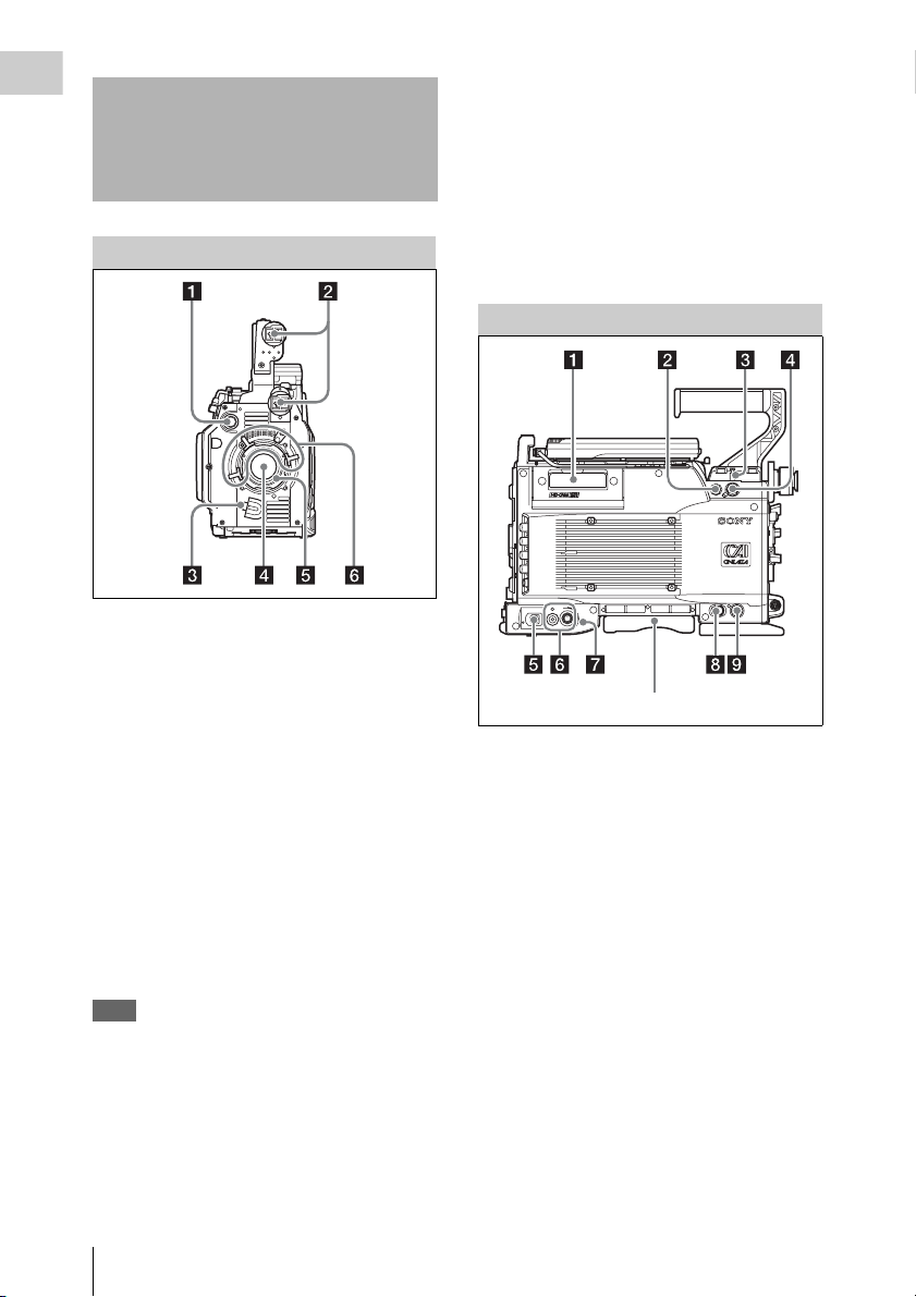
Front Panel
a VF (viewfinder) connector (20-pin)
Connect an optional viewfinder.
e Lens mount
Attach the lens. When no lens is mounted, keep
the lens mount cap fitted for protection from dust.
For details, see “Mounting the Lens” (page 31).
f Lens fixing lever
Push these levers downward to secure the lens in
the lens mount. To remove the lens, pull up on th e
lever.
Left Side
b Viewfinder shoes
When you attach the supplied viewfinder shoe
assembly to the handle, you can mount a
viewfinder on either of two shoes.
The attachment position of both viewfinder shoes
can be adjusted up and down.
For details, see “Attaching the Viewfinder” (page
32).
c LENS connector (12-pin)
If you mount an optional lens with a cable,
connect the cable to this connector. You can
control the functions of the lens through this
connector.
Note
Do not connect a device whose maximum rated current
is 1 A or higher to the LENS connector.
d Lens mount cap
Cover the lens mount with this cap when a lens is
not attached. The cover may be removed by
rotating the lens fixing lever upward.
Locations and Functions of Parts
16
Shoulder pads
a Cassette insertion slot
Insert cassettes.
For details, see “Loading and Unloadin g Cassettes”
(page 84).
b CTRL (VTR) (control panel) connector
Connect the cable of the supplied control panel. A
short cable is connected when the unit is shipped
from the factory. You can exchange the short
cable for the supplied extension cable.
For details, see “Attaching the C ontrol Panel” (page
37).
c Measure hook/focus reference mark (φ )
For actual measurement of the distance from a
subject, you can fix the end of a tape measure to
the hook.
A mark on the side panel (φ) indicates the
reference focus position.
d CTRL (CAM) (assistant panel)
connector
Connect the cable of the optional AP-1 Assistant
Panel.
For details, see “Attaching the AP-1 Assistant Panel
(Optional)” (page 39).
e Power ON (])/OFF (1) switch and
indicator
Push the switch to the ON side to power the unit
on (the indicator lights). Push it to the OFF side to
power the unit off (the indicator goes out).
f EARPHONES jack and LEVEL knob
Use the jack to attach earphones or stereo
headphones equipped with a stereo miniplug, for
use in monitoring audio during recording and
playback. Adjust the audio level with the LEVEL
knob.
A warning sound is heard through the earphones
or headphones when an error occurs.
Note
Some L-type mini plugs cannot be connected. Use a
straight type mini plug.
For details on the warning tone, see “Warning
System” (page 200).
g AUDIO indicator
Lights when the audio level meters (see page 26)
exceed a certain level.
h HD SDI MON1 (HDSDI monitor output
1) connector (BNC type)
Output HDSDI signals for display on a monitor.
You can select/set the output signals in the
Camera menu (see page 59). The same signals are
output from the HD SDI MON2 connector on the
rear panel.
i EXT I/O (external control) connector
(5-pin)
Use the connector for control via RS-232C.
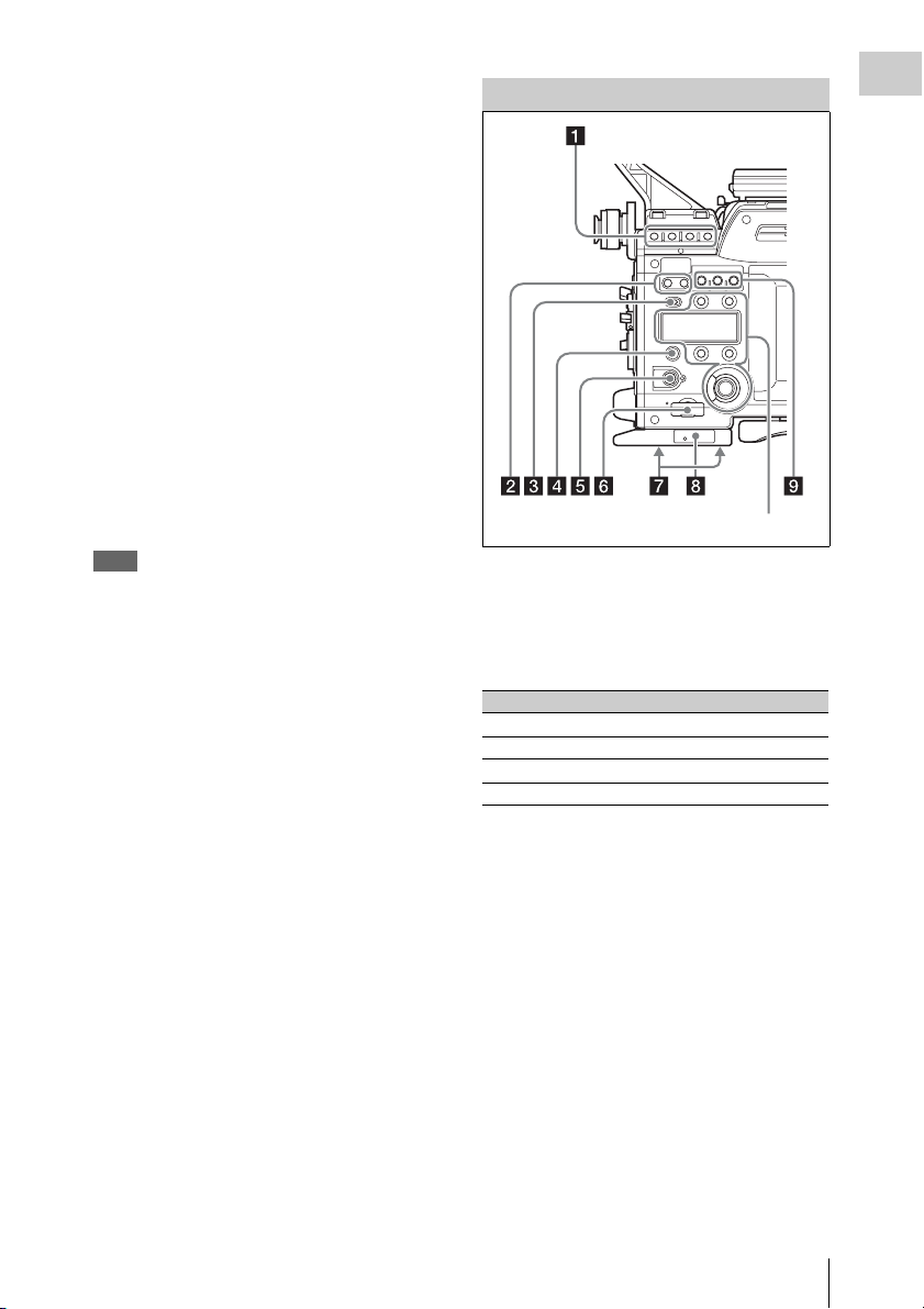
Right Side
Display/menu operations section (page 18).
a Assignable buttons 5 to 8
You can assign frequently used functions to these
buttons by menu settings. The following
functions are assigned when the unit is shipped
from the factory.
Switches Functions
5STOP
6PLAY
7REW
8F.FWD
For details, see “Assigning Functions to Assignable
Buttons/Switch” (page 54).
b Assignable buttons N and C
You can use the Camera menu to assign functions
to assignable buttons N and C. They are set to
OFF (disabled) when the unit is shipped from the
factory.
For details, see “Assigning Functions to Assignable
Buttons/Switch” (page 54).
Chapter 1 Overview
c LOCK switch
When slid to the right, locks the operation buttons
on the right-side panel.
If you wish, you can set this switch so that it locks
all buttons except the RUN button. Make this
setting on the <SUBDISPLAY 2> page (see page
122) of the Camera >USER (OPERATION)
menu.
Locations and Functions of Parts
17
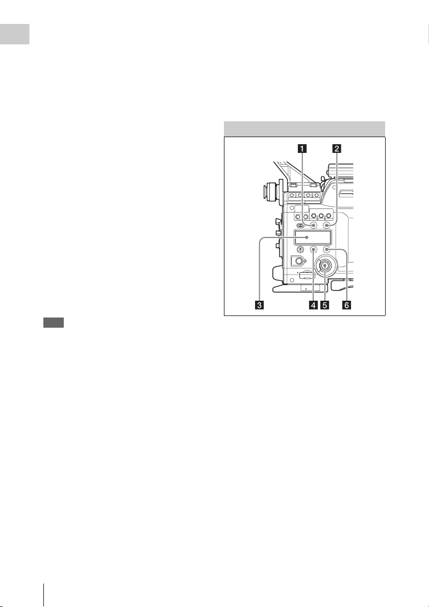
d Assignable 4/AUTO BLK BAL (auto
Chapter 1 Overview
black balance) switch
Push the switch downward to the AUTO BLK
BAL side to start the auto black balance
adjustment.
You can use the Camera menu to assign a
function to the 4 position (upper position). This
position is set to OFF (disabled) when the unit is
shipped from the factory.
For details, see “Assigning Functions to Assignable
Buttons/Switch” (page 54).
e RUN button and indicator
Starts and stops recording. The indicator lights
during recording, and fl ashes when low voltage or
an error is detected.
For more information about the indicator operation,
see “Warning/Error Messages” (page 202).
f “Memory Stick” slot
Allows you to insert a “Memory Stick”.
The access lamp lights in red while the unit is
writing or reading data to/from a “Memory
Stick”. You can use “Memory Stick PRO” or
“Memory Stick PRO Duo” media with this unit.
(“Memory Stick PRO Duo” media can be used
without any adaptor.)
Note
When the access lamp is lit in red, do not insert/remove
the “Memory Stick” or turn off the unit.
See “File Configuration ” (page 186) for information
about data files that can be handled with “Memory
Stick” media.
For details on “Memory Stick” media, see “Using a
“Memory Stick”” (page 191).
i Assignable buttons 1 to 3
You can assign frequently used functions to these
buttons by Camera menu settings. They are set to
OFF (disabled) when the unit is shipped from the
factory.
For details, see “Assigning Functions to Assignable
Buttons/Switch” (page 54).
Display/Menu Operations Section
For details, see “Basic Operations in the
Subdisplay” (page 44) or “Basic Camera Menu
Operations” (page 124).
a VF (viewfinder) MENU/DISPLAY
button
Displays and hides menus in the subdisplay and
viewfinder.
g Tripod screw holes
Two screw holes (for 3/8-inch camera screws) are
provided on the bottom-side panel.
h Riser plate/focus reference mark (φ)
This is a plate for attaching movie accessories. It
has a mark to show the focus standard position. A
wrench (2.5 mm) for use in attaching and
detaching the viewfinder is stored inside. When
you want to use a tripod with the optional VCT14 Tripod Attachment, exchange the riser plate
for the supplied V-shoe plate.
See “To use the optional VCT-14 Tripod
Attachment” (page 37) for more information about
attaching the V-shoe plate.
Locations and Functions of Parts
18
b CANCEL/STATUS button
Cancels settings made in the subdisplay and
viewfinder, or returns the display to a previous
state. When the Camera menu is not displayed,
you can press this button to display information
about the status of the unit in the subdisplay and
viewfinder.
See “Viewing Settings and Indications in the
Viewfinder” (page 64) for details about the status
information that appears

c Subdisplay
Displays the Camera menu and unit settings. If
you are using the optional AP-1 Assistant Panel,
the same information appears in the subdisplay of
the AP-1.
d PAGE button
In subdisplay screens, switches to the next page
or confirms settings.
e MENU SEL (selection)/ENTER dial
In subdisplay and viewfinder screens, confirms
settings. When the Camera menu is displayed in
the subdisplay and viewfinder, turn the dial to
select menu items.
Note
When you turn the dial, stop it at a position where you
feel a click. If you force the dial to stop at a non-click
position, the operating stability of the dial on the AP-1
side may be affected.
f SET button
In subdisplay screens, returns to the previous
page. When this button is held down for one
second or longer, the screen enters settings
modification mode.
Rear Panel
b Tally indicator and ON/OFF switch
When the switch is set to ON, the tally indicator
lights during recording. The indicator flashes
when low voltage or an error is detected. You can
set the switch to OFF to prevent the indicator
from lighting or flashing.
See “Warning System” (page 200)” for more
information about when the tally indicator flashes.
c GENLOCK IN (external sync signal
input) connector (BNC type)
Used for input of an external genlock signal (HD
tri sync).
d TC IN (timecode input) connector
(BNC type)
Connect to the timecode output connector of a
timecode generator, VTR, or other external
device. Use this connector when you want to lock
the internal timecode generator to external
timecode.
e TC OUT (timecode output) connector
(BNC type)
Connect to the timecode input connector of a
timecode reader, VTR, or other external device.
The output signal depends on the setting of TC
Setup >OTHERS (MAIN) >TC OUT in the VTR
menu (see page 174).
Chapter 1 Overview
a Battery attachment shoe
Attach a battery or AC adaptor.
For details, see “Co nnecting a Power Supply” (page
29).
f TEST OUT connector (BNC type)
Outputs an analog signal selected in the Camera
menu (see page 59).
g DC OUT (DC power output) connector
(4-pin, male)
Supplies 12 V DC power. You can connect the
power cord of the WRR-861 UHF Synthesized
Tuner Unit to this connector.
h DC IN 11-17V (DC power input)
connector (4-pin)
Connect the DC power cord of an AC-DN2B/
DN10 AC Adaptor.
For details, see “Conn ecting a Power Supply” (page
29).
i AUDIO IN (audio input) CH-1/CH-2
connectors (XLR type 3-pin, female
type) and input selection switches
Input audio signals to the CH-1 and CH-2
connectors.
Locations and Functions of Parts
19
Set the input selection switches according to the
type of the connected signal source.
Chapter 1 Overview
LINE: When a line-level (+4 dBu) signal source
is connected
MIC: When an external microphone is connected
(no power is supplied.)
MIC +48V ON: When an external microphone is
connected (+48 V power is supplied.)
j HD SDI OUT A/B connectors (BNC
type) and ON/OFF switch (when the
HKSR-9001 is installed)
When the switch is set to ON, HDSDI signals are
output from the A and B connectors. When the
switch is set to OFF, no signals are output.
See “What Are Dual Link and 3G?” (page 212) for
more information about HDSDI signal output.
k REMOTE connector (8-pin)
Connect an external control device, such as the
RM-B150/B750 Remote Control Unit.
l AUX IN (auxiliary input) connector
(BNC type) (when the HKSR-9001 is
installed)
1.5G single link (4:2:2 30PsF or less) HDSDI
signals can be input to this connector and
recorded. Connect an external device to increase
the number of audio input channels, or to
synchronize this unit to the output of an HD
device.
When you use this connector for HDSDI input,
set SYSTEM Setup >FORMAT >INPUT SEL
(see page 180) in the VTR menu to AUX Input.
m HD SDI MON2 (HDSDI monitor
output 2) connector (BNC type)
Use in the same way as the HD SDI MON1
connector on the left-side panel (see page 17).
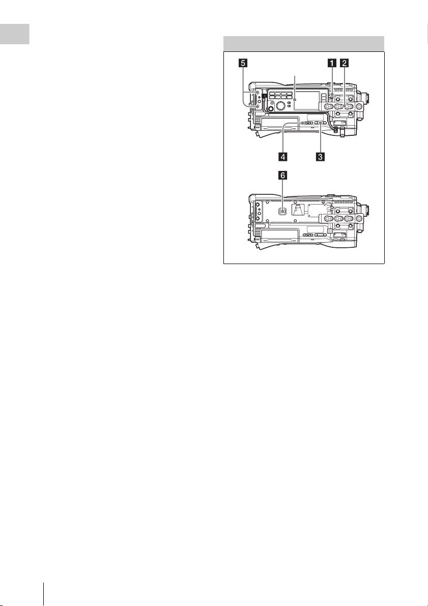
Upper Panel
Control panel
(page 21)
With control panel detached
a Lock release button
When removing the control panel, use this button.
For details, see “Attaching the C ontrol Panel” (page
37).
b Handle
Use to carry the unit.
You can attach an accessory to the seven screw
3
/8" × 4, 1/4" × 3) on the top of the handle.
holes (
You can also attach the CAC-12 Microphone
Holder to the side of the handle.
For details, see “Using a Microphone” (page 34).
c Assistant panel attachment screws
Attach the optional AP-1 Assistant Panel or the
CAC-12 Microphone Holder.
For details, see “Attaching the AP-1 Assistant Panel
(Optional)” (page 39) or “Using a Microphone”
(page 34).
Locations and Functions of Parts
20
d Cable holder attachment screws
Attach the supplied cable holder to hold the cable
of the control panel o r the optional AP-1 Assistant
Panel.
e Accessory attachment screw holes
You can attach accessories to the two screw holes
3
/8" × 1, 1/4" × 1).
(
f EJECT button
Pressing this button opens the lid of the cassette
insertion slot, allowing you to take out the
inserted cassette.
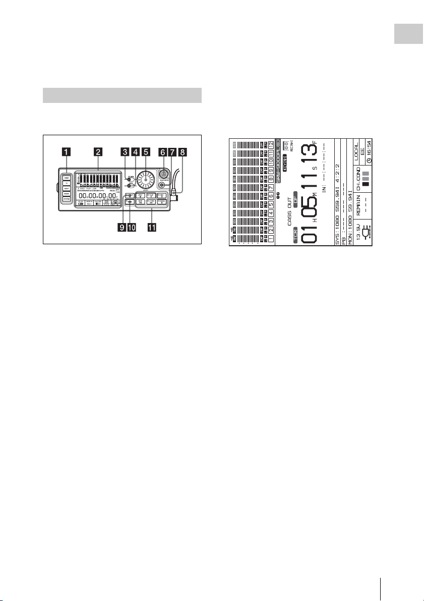
Control Panel
The control panel is used mainly for control of the
VTR module.
For details, see “Display” (page 26).
You can rotate the display to display it vertically
(rotated 90 degrees to the left).
To change the display, press the HOME button
while holding the FUNC and BACK buttons
down.
To return the display to its original orientation,
press the HOME button again while holding the
FUNC and BACK buttons down.
Chapter 1 Overview
a VTR menu selection buttons
Select one of the VTR menus or the Camera menu
to be shown on the display.
HOME button: Displays the HOME screen. The
HOME screen displays audio levels,
operating status, warnings, time data, and
other information.
TC button: Displays the TC (timecode) Setup
menu (see page 173). This menu allows you
to switch between LTC and VITC, to switch
between DF and NDF, and to display
timecode on an external monitor.
VIDEO button: Displays the VIDEO Setup
menu. The menu allows you to perform
Camera menu operations (see page 124).
AUDIO button: Displays the AUDIO Setup
menu (see page 176). This menu allows you
to make settings related to audio.
SYSTEM button: Displays the SYSTEM Setup
menu (see page 178). This menu allows you
to make settings related to the entire system,
such as recording format, power, and test
signal output.
For details on VTR menus, see “VTR Menu List”
(page 173).
b Display
Displays VTR menus, audio levels, warnings,
operating status, time data, remaining tape time,
and remaining battery power.
c KEY INHI (inhibit) switch
When the KEY INHI item (see page 181) in the
SYSTEM Setup menu is set to ALL, setting this
switch to ON disables operation buttons, to
prevent misoperations due to accidental button
operations.
ON: All operation buttons are disabled.
OFF: During recording, only the STOP button
and PAUSE button are enabled. All buttons
are enabled when the unit is not in recording
mode.
When the KEY INHI item in the SYSTEM Setup
menu is set to MAP, the operation buttons follow
the settings of the LOCAL KEYMAP item.
d LIGHT switch
The backlight comes on when this is set to ON.
e ADJUST knob
Use to adjust audio levels, etc.
f SELECT/ENTER dial
When a menu is displayed, you can turn this dial
to move the cursor, and press it to select and
confirm settings.
g BACK button
When a menu is displayed, you can press this
button to back up one level in the menu structure.
Locations and Functions of Parts
21

h Control panel connection cable
Connect to the CTRL (VTR) connector.
Chapter 1 Overview
j FUNC (function) button and indicator
When the tape transport control buttons are
pressed with this button held down, the functions
i EJECT button and indicator
Pressing the button opens the cover of the cassette
insertion slot so that you can remove a cassette.
The indicator lights during removal.
of the buttons change.
The indicator lights when the FUNC button is
turned on.
For details, see “ qa Tape transport control buttons”
(page 22).
Pressing the HOME button with this button held
down switches the display at the bottom of the
HOME screen.
For details, see “Display” (page 26).
k Tape transport control buttons
Use these buttons for tape transport operations. The functions of the buttons change when they are pressed
together with the FUNC button.
Name Pressed alone Pressed with FUNC button
STOP button Stops tape transport.
Pressing this button while in
standby on mode resets the still
timer (see page 182). Pressing the
button while in standby off mode
puts the unit into standby on mode.
Puts the unit into standby off mode.
Locations and Functions of Parts
22

Name Pressed alone Pressed with FUNC button
PLAY button and indicator Starts playback. (The indicator
lights during playback.) To start
recording, press this button with
the REC button held down.
Pressed with tape transport stopped:
Searches for the recording end point and
then stops. When SYSTEM Setup
>SERVO >EOS MODE in the VTR
menu is set to “NORM” (factory default
setting), rewinds for about five seconds
and then plays for about 10 seconds. If
the recording end point is located in that
section, playback stops at that point and
the unit enters recording pause mode. If
the recording end point is not located in
that section, playback continues for
about 10 seconds and then stops. When
SYSTEM Setup >SERVO >EOS MODE
is set to “LONG”, the 10-second search
time limit described above does not
apply. Once playback starts, the search
continues until the recording end point is
found.
For details, see “Continuous recording
in other cases” (page 92).
Pressed with recording paused: Plays back
the most recently recorded material, and
then returns to recording pause mode
(recording review). When SYSTEM
Setup >SERVO >REC REVIEW in the
VTR menu is set to “NORM” (factory
default setting), one press of this button
rewinds the tape about three seconds and
then starts playback. You can keep the
PLAY button pressed together with the
FUNC button to rewind the tape as long
as the buttons are held down (up to a
maximum of 10 seconds), and then start
playback. Recording review allows you
to check whether the material was
recorded correctly. When SYSTEM
Setup >SERVO >REC REVIEW is set to
“ALL”, one press of this button rewinds
up to the beginning of the most recently
recorded cut and then starts playback.
Note
Recording review is available when recording
is paused after recording at least three
seconds.
Chapter 1 Overview
Locations and Functions of Parts
23

Name Pressed alone Pressed with FUNC button
Chapter 1 Overview
REC button and indicator Pressing PLAY button with this
button held down starts recording.
(The indicator lights during
recording.)
Pressing the button with recording
paused in standby off mode puts
the unit into standby on mode. If
you press this button during
playback, fast forward, or rewind,
the unit enters E-E mode.
a)
Temporarily memorizes the time data of the
current position (Mark In). Mark In data is
displayed in the format “IN: xx:xx:xx:xx” in
the time data field of the display, and can be
used for cueup.
Note
The Mark In data is only temporarily
memorized in the unit’s internal memory. It is
erased when you eject the cassette.
In this
mode you can monitor E-E signals
b)
output from the HD SDI OUT
A/B connectors or the HD SDI
MON1/2 connectors.
REW (rewind) button and
indicator
Rewinds the tape. (The indicator
lights during rewinding, and goes
out when the rewinding is
finished.)
When the REW button is pressed
again during rewinding, the
operation changes to search, in the
same way as when the button is
pressed together with the FUNC
button (searching at the speed in
effect when the most recent search
was interrupted).
Executes reverse direction searches. With
each press, the search speed changes in the
order × 2 t × 5 t × 8 t × 2 normal
speed.... If a search is interrupted by another
operation, the next search is performed at the
speed in effect at the time of the interruption.
Note
When you are using the unit at the 880 Mbps
recording rate, × 8 normal speed search is
disabled.
For details on recording rates, see FORMAT
>SIGNAL in the SYSTEM Setup menu
(page 179).
F FWD (fast forward)
button and indicator
Fast forwards the tape. (The
indicator lights during fast
forwarding, and goes out when the
fast forwarding is finished.) When
the F FWD button is pressed again
during fast forwarding, the
operation changes to search, in the
same way as when the button is
pressed together with the FUNC
button (searching at the speed in
effect when the most recent search
was interrupted).
Executes forward direction searches. With
each press, the search speed changes in the
order × 2 t × 5 t × 8 t × 2 normal
speed.... If a search is interrupted by another
operation, the next search is performed at the
speed in effect at the time of the interruption.
Note
When you are using the unit at the 880 Mbps
recording rate, × 8 normal speed search is
disabled.
For details on recording rates, see FORMAT
>SIGNAL in the SYSTEM Setup menu
(page 179).
Locations and Functions of Parts
24

Name Pressed alone Pressed with FUNC button
PAUSE button and
indicator
a) E-E mode: A state in which E-E (electric to electric) signals can be monitored. Commonly used to monitor the camera
picture or the input signal before either is recorded.
b) E-E signal: A signal which passes solely through internal circuitry, and not through pathways in which magnetic
conversion takes place, such as magnetic heads and tapes.
Pauses tape transport. (The
indicator flashes during pause.) To
resume tape transport, press the
button again.
Cues up a time data position specified with
FUNC+REC buttons or SYSTEM Setup
>EDIT >IN POINT in the VTR menu and
stops. The specified time data (Mark In data)
is displayed in the format “IN: xx:xx:xx:xx”
in the time data field of the display.
Turning the ADJUST knob during the paused
state performs jog search, and a shuttle still is
displayed whenever you stop turning. The
image and the TCR value may not always
match. Press the PAUSE button again to
return to the paused state.
Note
The Mark In data is only temporarily
memorized in the unit’s internal memory. It is
Chapter 1 Overview
Locations and Functions of Parts
25
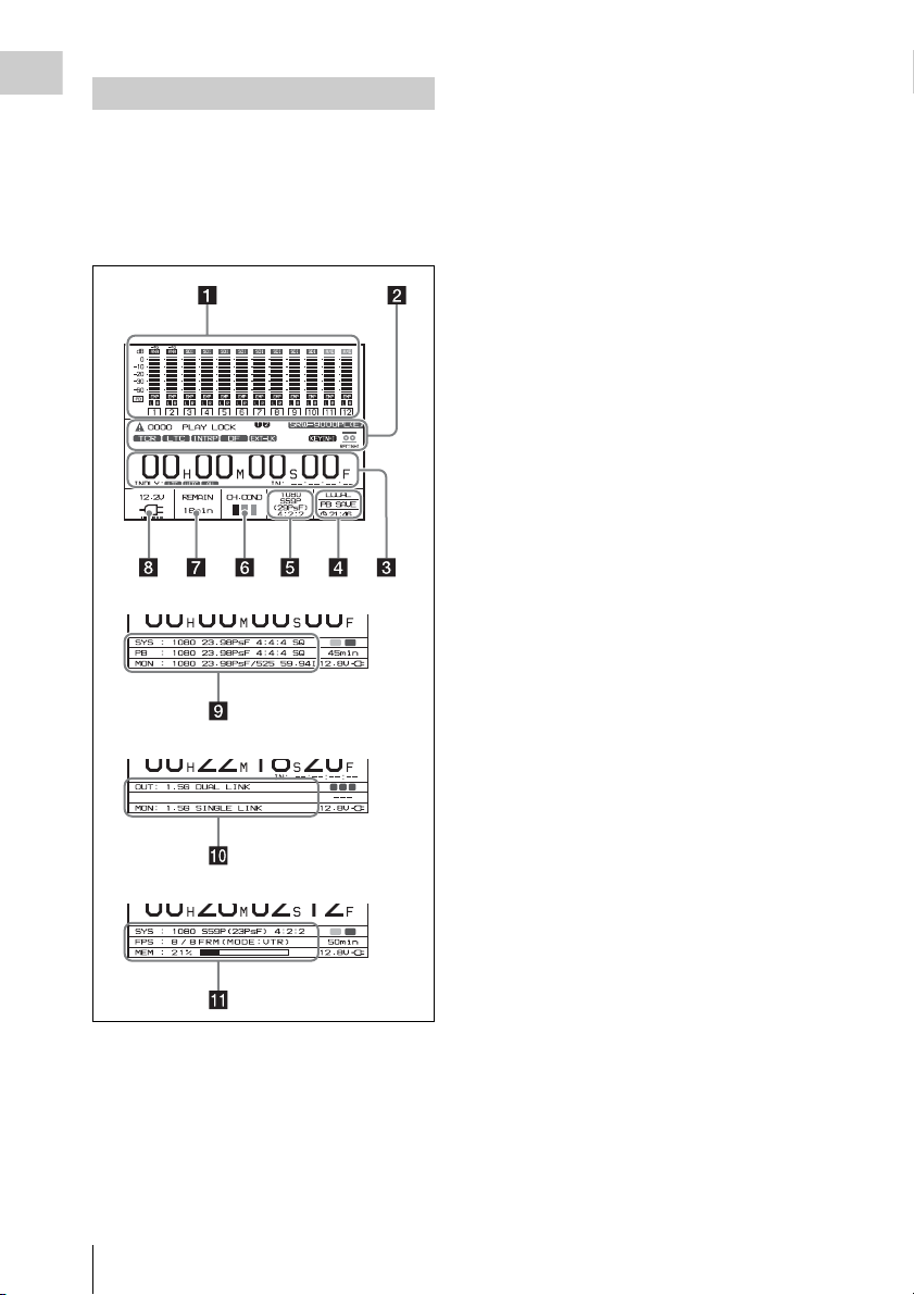
Display
Chapter 1 Overview
When you press the HOME button with the
FUNC button held down, sections 4 to 7 are
replaced by the display shown in section 9.
This manual refers to the screen shown below as
the HOME screen.
b Operation status and warnings
Display the operation status of the unit and
warnings. The principal information items are as
follows.
TCR/TCG/UBR/UBG/CTL: Type of time data
being displayed.
LTC/VITC: When timecode is being displayed,
whether it is LTC or VITC.
1)
INTRP: Indicates that timecode could not be
read accurately, and has been interpolated.
DF/NDF: Whether the system is in DF (drop
frame) or NDF (non-drop frame) mode.
EXT-LK: Timecode is locked to external
timecode.
KEY INHI: The KEY INHI switch is set to ON.
REC INHI: The cassette is record inhibited.
SRW-9000PL(E) or SRW-9000(PL,E): Model
name display. When the optional HKSR90PL Upgrade Kit is installed on the SRW9000, “SRW-9000(PL,E)” is displayed.
“E” shows that an enhanced processor is
installed, which allows recording in RGB
4:4:4 or 4:4:4 HQ 12bit format and using SLOG gamma.
When SYSTEM Setup >FORMAT >INPUT
SEL in the VTR menu is set to “AUX Input”
with the optional HKSR-9001 installed, the
indication changes as follows.
SRW-9000(E)t9000(E)AUX
SRW-9000(PL,E)t9000(PL,E)AUX
[1]/[2]: Option board installation status. “1”
represents the HKSR-9001, and “2”
represents the HKSR-9002.
1) VITC (Vertical Interval Time Code): Timecode
inserted into the vertical blanking interval. This type
of timecode can be read even during very slow
playback.
For details on warnings, see “Warning/Error
Messages” (page 202).
a Audio level meters
Display recording audio levels in recording and
E-E modes. Display playback audio levels during
playback.The indications in the top row show the
audio input signal types.
The numbers 1 to 12 at the bottom are the
numbers of audio tracks on the tape.
Locations and Functions of Parts
26
c Time data
Displays time data for the current tape position.
The type of time data is CTL
1)
(tape running
time), timecode, or user bits, as selected with TC
Setup >TIMER SEL in the VTR menu (see page
173).
When Mark In data has been set by the FUNC +
REC buttons or SYSTEM Setup >EDIT >IN
POINT in the VTR menu, it is displayed in the
format “IN: xx:xx:xx:xx” beneath (right side) the
time data for the current tape position.

When no Mark In data has been set,
“IN: --:--:--:--” appears. When TC Setup
>OTHERS(M AIN) >LTC Delay an d/or TC Setup
>OTHERS(MAIN) >VITC Delay in the VTR
menu are set to something other than “NO
Delay”, “IN DLY:” appears beneath (to the left
side) the time data of the current position and the
LTC and/or VITC indicators light to indicate the
item(s) set to something other than “NO Delay”.
1) CTL signal: This is a control signal consisting of a
pulse signal recorded longitudinally on the tape for
every frame of video.
d Status
Displays the unit’s control status (LOCAL), the
POWER mode (EE), and the real time.
Upper row: Unit’s control status
Middle row: POWER mode
Lower row: Real time
h Battery level/external power supply
voltage and current
Displays the current power level of the battery
pack. When the battery pack is fully charged, all
seven segments light up. As the battery pack
discharges, the segments go out from left to right.
When the battery pack is almost exhausted, the
voltage indication and the tally indicator flash,
and a warning tone sounds intermittently. When
the battery pack is co mpletely exhausted, the tally
indicator flashes at a higher rate and the warning
tone sounds continuously.
For details, see “Warning System” (page 200).
The voltage actually used by the unit (slightly
lower than the input voltage) is shown.
For details on battery voltage and so on, see
“Checking the Power and Voltage” (page 30).
Chapter 1 Overview
e Signal format
Displays the format of recording signals.
f Channel condition/RF indicator
During playback, “CH.COND” appears and one
of three bars (green, yellow, and red) lights to
indicate the playback signal condition.
Green bar: Playback signal quality is good.
Yel l o w b ar : Playback signal quality is degraded,
but playback is possible.
Red bar: Playback signal quality is degraded. If
this continues, head cleaning or internal
inspection is needed.
During playback with manual tracking control,
the “CH.COND” indication flashes in yellow (see
page 95). “CH.COND” flashes during auto
tracking operation.
During recording, “RF” appears and a green bar
or a red bar lights to indicate the recording signal
condition. Normally the green bar lights. If a
recording problem occurs, the red bar lights.
Green bar: Recording signal quality is good.
Red bar: Recording signal quality is degraded. If
this continues, head cleaning or internal
inspection is needed.
g Remaining tape time
Displays the time remaining on the tape. “TOP” is
displayed at the start of the tape, and “END” is
displayed at the end.
The time display flashes when the tape is within
three minutes of the end.
i Signal formats
When you press the HOME button with the
FUNC button held down, displays the system
(SYS), playback (PB), and monitor (MON)
output signal formats, in that order from the top
row.
When the unit is in one of the following modes,
an alphabetic character indicating the mode
appears before the number of lines.
T: Auto Timer Rec
M: Manual Timer Rec
C: Cache Rec
When SR Motion is used, “S” appears before the
system frequency. When you play a tape that was
recorded with SR Motion, the FPS value in SR
Motion recording is shown in the playback
frequency position (see page 103).
See Chapter 6 “SR Motion (With HKSR-9002
Installed)” (page 101) for more information about
the SR Motion function.
j HDSDI output
When the optional HKSR-9001 is installed,
displays the signal formats of monitor output
(MON) and the output of the HD SDI OUT A/B
connectors (OUT). The display switches when
you press the HOME button with the FUNC
button held down.
See “What Are Dual Link and 3G?” (page 212) for
more information about HDSDI output.
Locations and Functions of Parts
27
k SR Motion
When SYSTEM Setup >FORMAT >SELECT
Chapter 1 Overview
FPS in the VTR menu is set to “ON” and the
signal format is being displayed, pressing both the
FUNC and HOME buttons together displays the
FPS or FRM on the second line and the memory
level on the third line.
See Chapter 6 “SR Motion (With HKSR-9002
Installed)” (page 101) for more information about
the SR Motion function.
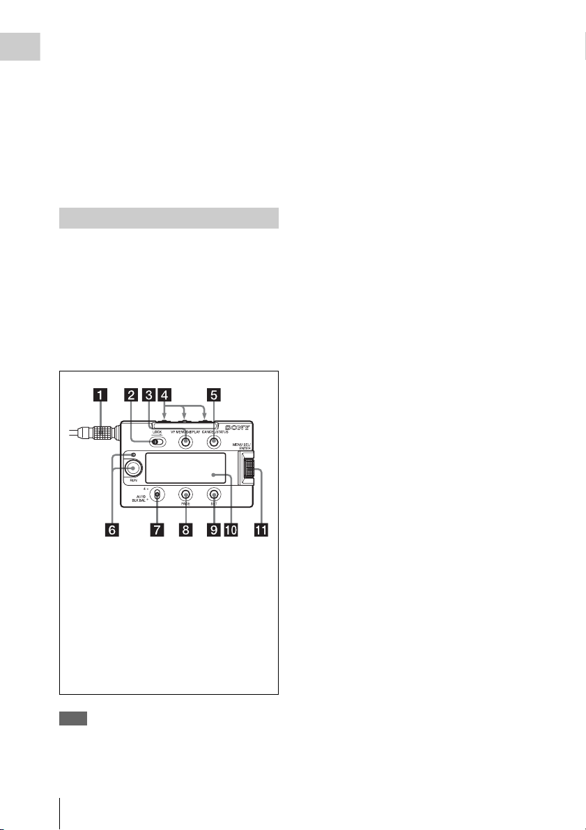
AP-1 Assistant Panel (Optional)
By connecting the cable to the CTRL (CAM)
connector, you ca n operate the unit remotely. You
can also connect the AP-1 Assistant Panel to the
unit’s left -side panel. The AP-1 p rovides the same
functions as the switches and buttons on the unit’s
right-side panel.
See “Attaching th e AP-1 Assistant Panel (Optional)”
(page 39) for more information about attaching the
AP-1.
AP-1 cable while operating the subdisplay. If a ?
symbol is shown on
the subdisplay, register the setting before
disconnecting or connecting the cable.
1 Connection cable
2 LOCK switch (page 17)
3 VF MENU/DISPLAY button (page 18)
4 Assignable switches 1 to 3 (page 18)
5 CANCEL/STATUS button (page 18)
6 RUN button and indicator (page 18)
7 Assignable 4/AUTO BLK BAL switch
(page 18)
8 PAGE button (page 19)
9 SET button (page 19)
q; Subdisplay (page 19)
qa MENU SEL/ENTER dial (page 19)
Note
The cursor in the subdisplay may move
unexpectedly if you disconnect or connect the
Locations and Functions of Parts
28
Chapter2 Preparations
Connecting a Power Supply
WARNUNG
Akkus dürfen keinesfalls übermäßiger
Wärmeeinwirkung ausgesetzt werden, wie z.B.
Sonneneinstrahlung, Feuer o. ä.
To attach the battery pack
Chapter 2 Preparations
This unit operates on DC 12 V (11 to 17 V)
power. Supply power by connecting it directly to
a DC power source or by using a battery pack or
AC adaptor.
Note
For safety, use only the Sony products listed below.
• BP-GL95 Lithium-ion Battery Pack
• AC-DN2B/DN10 AC Adaptor
Using a Battery Pack
When a BP-GL95 Battery Pack is used, the
continuous operating time is approximately 80
minutes.
Notes
• The battery pack operating time depends on how often
the battery pack is used, and on the ambient
temperature when it is used.
• Before use, charge the battery pack with the specified
charger.
For details on the battery charging procedure,
refer to the battery charger operation manual.
• The battery pack may not be recharged fully if
you charge it immediately after use, while it is
still warm.
• Remove the battery pack if the unit will be out
of use for an extended period.
WARNING
Batteries shall not be exposed to excessive heat such as
sunshine, fire or the like.
AVERTISSEMENT
N’exposez pas les batteries à une chaleur excessive, au
soleil ou près d’un feu par exemple.
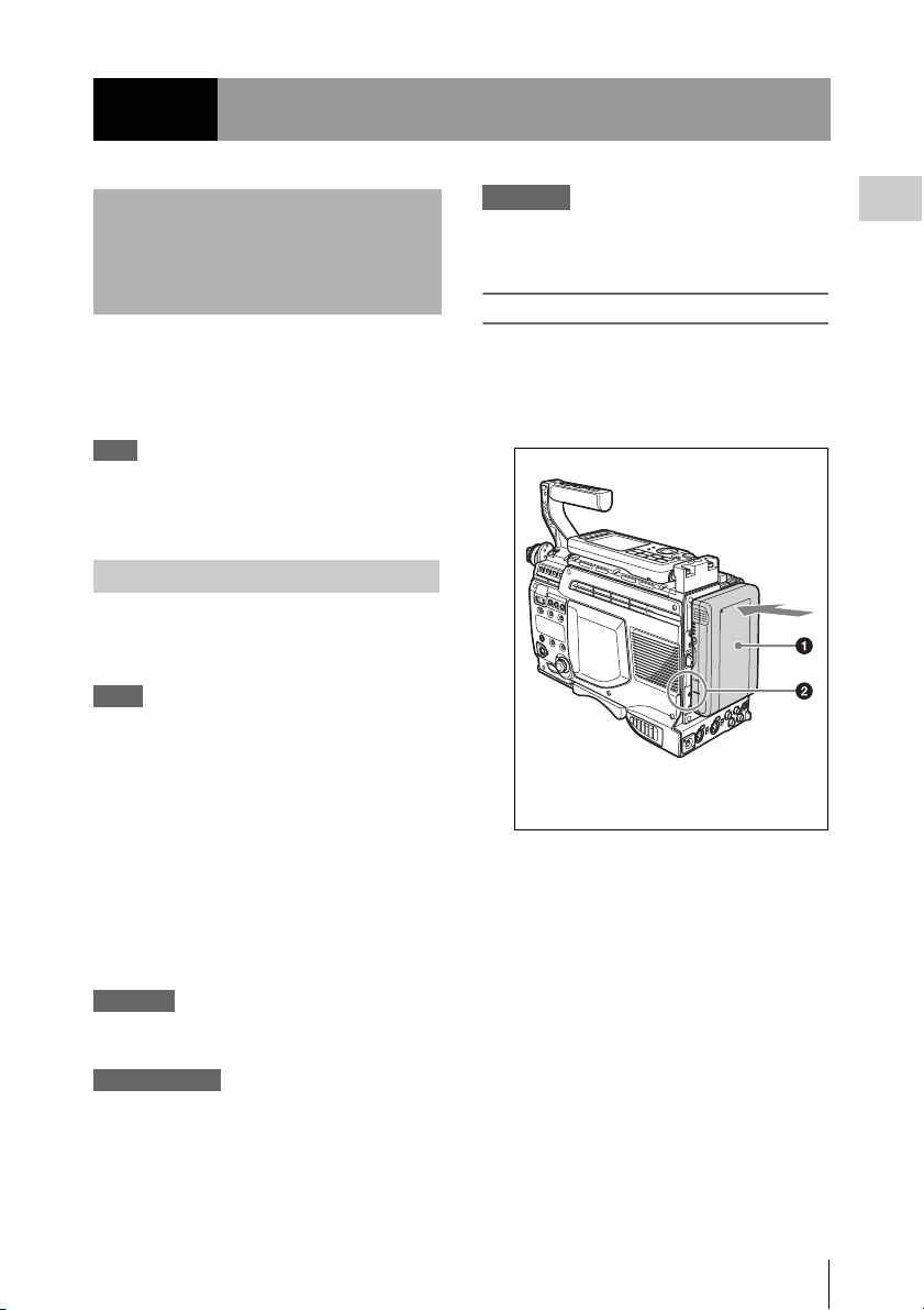
1 Press the battery pack against the back
of the unit, aligning the line on the side
of the battery pack with the matching
line on the unit.
1Battery pack
2Align these lines.
2 Slide the battery pack down until its
“LOCK” arrow points at the matching
line on the unit.
Connecting a Power Supply
29
Chapter 2 Preparations
the AC power cord (supplied with the AC
adaptor) to an AC power source.
Turning on the Power
Push the power ON (|)/OFF (1) switch to the ON
side. The power indicator lights when the unit is
powered on.
Power is supplied to the viewfinder connected to
the VF connector and to the lens connected to the
LENS connector, and 12 V power is supplied
from the DC OUT connector.
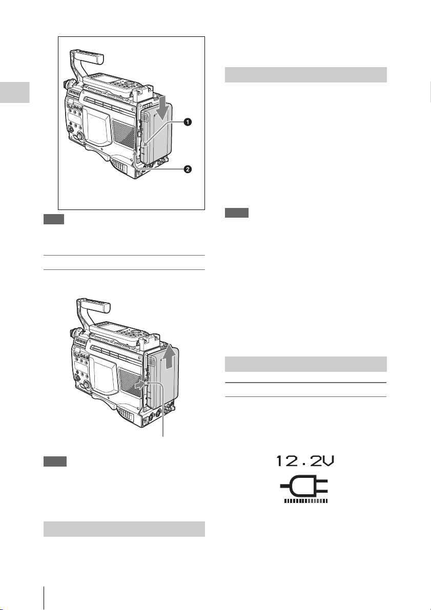
1“LOCK” arrow
2Matching line on the unit
Note
If the battery pack is not attached correctly, the terminal
may be damaged.
To detach the battery pack
With the unit powered off, hold the release button
in and pull the battery pack up.
Release button
Notes
• Be careful never to remove the battery pack during
recording and playback.
• Make sure to power the unit off before replacing the
battery pack.
Using AC Power
Use an AC-DN2B/DN10 AC adaptor.
Connect a DC power cord (not supplied) to this
unit’s DC IN 11-17V connector, and then connect
Push the switch to the OFF side to power the unit
off. The indicator goes out when unit is powered
off.
Notes
• To protect tapes, do not power the unit off with a
cassette loaded. Always eject the cassette before
powering the unit off.
If you do power the unit off with a cassette loaded, the
power does not go off immediately. This is to protect
the tape. The power goes off after the tape has been
returned to the unthreaded position.
• Do not remove the battery pack or disconnect the DC
power cord before the power goes off.
• After powering the unit off, wait at least two seconds
before powering it on again.
• Always make sure that the unit is powered off before
connecting accessories.
Checking the Power and Voltage
To check the type of power being used
A battery mark appears in the lower left of the
control panel display when power is being
supplied from the battery attachment section.
A power plug mark appears when an AC adaptor
is selected as the power supply.
Note that this mark does not reflect the actual type
of power being used, but reflects the settings of
the following VTR menu items.
• SYSTEM Setup >BATTERY >BATT TYPE
• SYSTEM Setup >BATTERY >DCIN TYPE
Connecting a Power Supply
30
 Loading...