

Sony HKSR-5804 Installation Manual

NETWORK INTERFACE BOARD
HKSR-5804
INSTALLATION MANUAL
1st Edition
! WARNING
This manual is intended for qualified service personnel only.
To reduce the risk of electric shock, fire or injury, do not perform any servicing other than that
contained in the operating instructions unless you are qualified to do so. Refer all servicing to
qualified service personnel.
! WARNUNG
Die Anleitung ist nur für qualifiziertes Fachpersonal bestimmt.
Alle Wartungsarbeiten dürfen nur von qualifiziertem Fachpersonal ausgeführt werden. Um die
Gefahr eines elektrischen Schlages, Feuergefahr und Verletzungen zu vermeiden, sind bei
Wartungsarbeiten strikt die Angaben in der Anleitung zu befolgen. Andere als die angegeben
Wartungsarbeiten dürfen nur von Personen ausgeführt werden, die eine spezielle Befähigung
dazu besitzen.
! AVERTISSEMENT
Ce manual est destiné uniquement aux personnes compétentes en charge de l’entretien. Afin
de réduire les risques de décharge électrique, d’incendie ou de blessure n’effectuer que les
réparations indiquées dans le mode d’emploi à moins d’être qualifié pour en effectuer d’autres.
Pour toute réparation faire appel à une personne compétente uniquement.
HKSR-5804

Section 1
Installation
Purpose of this manual
This manual is an installation manual of Network I/F Board HKSR-5804.
This manual is intended for system and service engineers, so describes information regarding installation.
Related manual
Besides this installation manual, the following manual is available for HKSR-5804.
. SRW-5800 Maintenance Manual (available on request)
This manual describes the information for the maintenance of this unit and the information that premises the parts level service.
If this information is required, contact your local Sony Sales Office/Service Center.
1-1. Specifications
General
Dimensions (w/h) MY-115 Board: 355 x 183 mm
Mass MY-115 Board: approx. 1.03 kg
Power requirements +6.2V dc: 5.3 A
+3.3V dc: 1.8 A
Power consumption 38.8 W
1-2. Installation Overview
Components
. MY-115 Board (x1)
. Network panel assembly (x1)
Assembly of parts listed below
. Network 2 panel (x1)
. IF-1071 Board (incl. a modular jack) (x1)
. Coaxial cables with a BNC connector (x4)
. Connection cord (with modular plugs) (x1)
A ferrite core is attached.
. Operation manual (CD-ROM) (x1)
. Installation guide (x1)
. Installation manual (x1)
Applicable model
SRW-5800
HKSR-5804
1-1 (E)
Matching Connectors/Cables/Signal Inputs and Outputs
When external cables are connected to the connector of this unit, the hardware listed below (or equivalents) must be used.
Panel indication Matching connector (cable) Sony part No. Signal
AUX INPUT A BNC 75 Z, MALE 1-569-370-12 HD SDI signal input
AUX INPUT B BNC 75 Z, MALE 1-569-370-12 HD SDI signal input
AUX OUTPUT A BNC 75 Z, MALE 1-569-370-12 HD SDI signal output
AUX OUTPUT B BNC 75 Z, MALE 1-569-370-12 HD SDI signal output
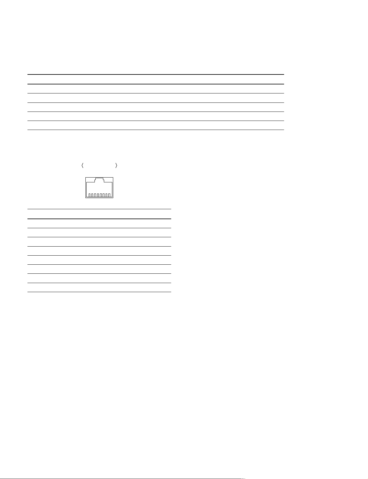
NETWORK 2 Commercially available
NETWORK 2: RJ-45 modular jack
Standard : Complied with IEEE 802.3ab (1000BASE-T)
External view
81
Pin No. I/O Signal
1 I/O TP0 (+)
2 I/O TP0 (_)
3 I/O TP1 (+)
4 I/O TP2 (+)
5 I/O TP2 (_)
6 I/O TP1 (_)
7 I/O TP3 (+)
8 I/O TP3 (_)
1-2 (E)
HKSR-5804
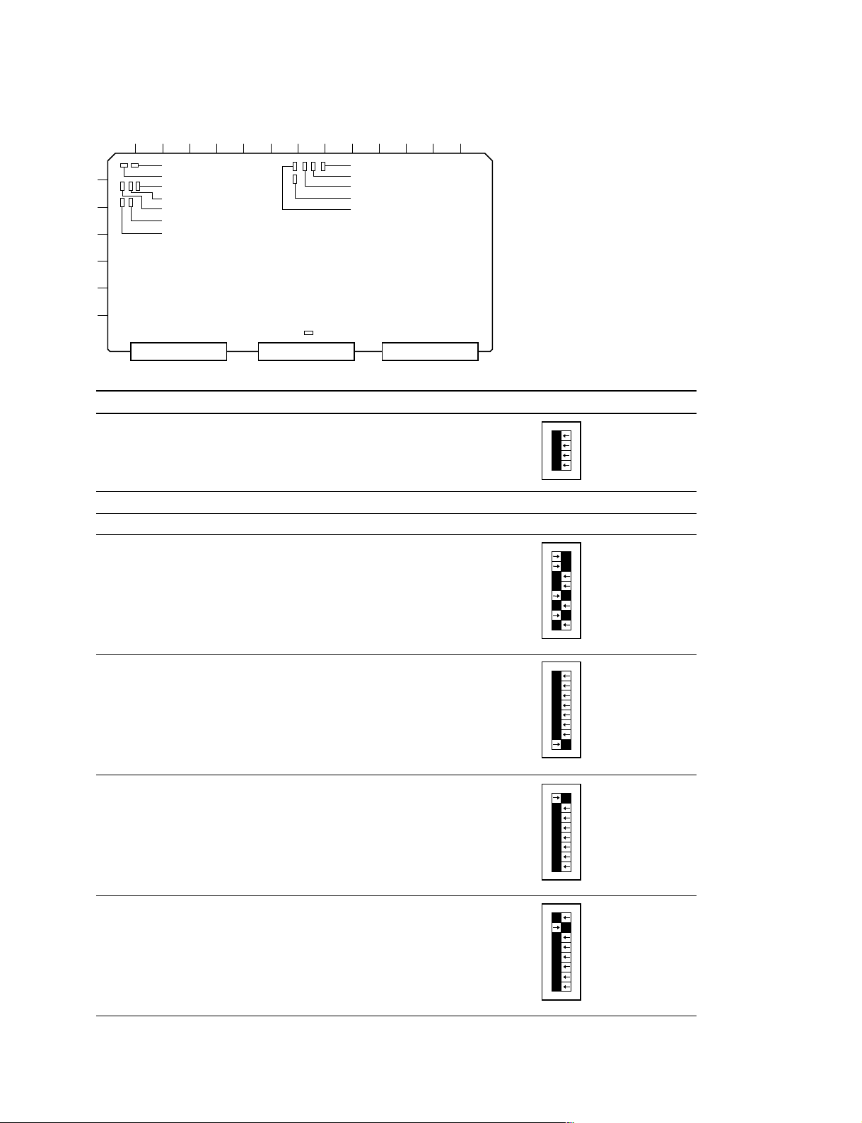
Description of the switch function on the MY-115 Board
A B C D E F G H J K L M NP
1
2
3
4
5
6
S1001
S1000
S1404
S1402
S1400
S1403
S1401
S4501
S4500
S3001
S900
S3000
7
S5000
Ref. No Name Description Factory setting
S900 PCI Factory use
1O
N
2
3
4
S1000 Reset System reset
S1001 — Factory use
S1400 — Factory use
S1401 — Factory use
1O
N
2
3
4
5
6
7
8
1O
N
2
3
4
5
6
7
8
S1402 — Factory use
S1403 — Factory use
HKSR-5804
1O
N
2
3
4
5
6
7
8
1O
N
2
3
4
5
6
7
8
1-3 (E)
 Loading...