

Sony SRW-5800, HKSR-5001, HKSR-5802, HKSR-5803SQ, HKSR-5803HQ Operation Manual

HD DIGITAL VIDEOCASSETTE RECORDER
SRW-5800
FORMAT CONVERTER BOARD
HKSR-5001
DIGITAL BETACAM/HDCAM PROCESSOR BOARD
HKSR-5802
RGB SQ PROCESSOR BOARD
HKSR-5803SQ
ADVANCED HQ PROCESSOR BOARD
HKSR-5803HQ
OPERATION MANUAL [English]
1st Edition (Revised 5)
Important Safety Instructions
• Read these instructions.
• Keep these instructions.
• Heed all warnings.
• Follow all instructions.
• Do not use this apparatus near water.
• Clean only with dry cloth.
• Do not block any ventilation openings.
Install in accordance with the manufacturer's
instructions.
• Do not install near any heat sources such as radiators,
heat registers, stoves, or other apparatus (including
amplifiers) that produce heat.
• Do not defeat the safety purpose of the polarized or
grounding-type plug. A polarized plug has two blades
with one wider than the other. A grounding type plug
has two blades and a third grounding prong. The wide
blade or the third prong are provided for your safety. If
the provided plug does not fit into your outlet, consult an
electrician for replacement of the obsolete outlet.
• Protect the power cord from being walked on or pinched
particularly at plugs, convenience receptacles, and the
point where they exit from the apparatus.
• Only use attachments/accessories specified by the
manufacturer.
• Use only with the cart, stand, tripod, bracket,
or table specified by the manufacturer, or sold
with the apparatus.
When a cart is used, use caution when moving
the cart/apparatus combination to avoid injury from tipover.
• Unplug this apparatus during lightning storms or when
unused for long periods of time.
• Refer all servicing to qualified service personnel.
Servicing is required when the apparatus has been
damaged in any way, such as power-supply cord or plug
is damaged, liquid has been spilled or objects have fallen
into the apparatus, the apparatus has been exposed to
rain or moisture, does not operate normally, or has been
dropped.
WARNING
To reduce the risk of fire or electric shock,
do not expose this apparatus to rain or
moisture.
To avoid electrical shock, do not open the
cabinet. Refer servicing to qualified
personnel only.
THIS APPARATUS MUST BE EARTHED.
This symbol is intended to alert the user to
the presence of uninsulated “dangerous
voltage” within the product’s enclosure
that may be of sufficient magnitude to
constitute a risk of electric shock to
persons.
This symbol is intended to alert the user to
the presence of important operating and
maintenance (servicing) instructions in
the literature accompanying the
appliance.
When installing the installation space must be secured in
consideration of the ventilation and service operation.
• Do not block the ventilation slots at the left side and right
side panels, and vents of the fans.
• Leave a space around the unit for ventilation.
• Leave more than 40 cm of space in the rear of the unit to
secure the operation area.
When the unit is installed on the desk or the like, leave at
least 4 cm of space in the left and right sides. Leaving 40
cm or more of space above the unit is recommended for
service operation.
WARNING: THIS WARNING IS APPLICABLE
FOR USA ONLY.
If used in USA, use the UL LISTED power
cord specified below.
DO NOT USE ANY OTHER POWER
CORD.
Plug Cap Parallel blade with ground pin
(NEMA 5-15P Configuration)
Cord Type SJT, three 16 or 18 AWG
wires
Length Minimum 1.5m (4 ft .11in.),
Less than 2.5 m (8 ft .3 in.)
Rating Minimum 10A, 125V
Using this unit at a voltage other than 120V
may require the use of a different line cord
or attachment plug, or both. To reduce the
risk of fire or electric shock, refer servicing
to qualified service personnel.
2

WARNING: THIS WARNING IS APPLICABLE
FOR OTHER COUNTRIES.
1. Use the approved Power Cord (3-core mains lead) /
Appliance Connector / Plug with earthing-contacts that
conforms to the safety regulations of each country if
applicable.
2. Use the Power Cord (3-core mains lead) / Appliance
Connector / Plug conforming to the proper ratings
(Voltage, Ampere).
If you have questions on the use of the above Power Cord
/ Appliance Connector / Plug, please consult a qualified
service personnel.
CAUTION
The apparatus shall not be exposed to dripping or
splashing. No objects filled with liquids, such as vases,
shall be placed on the apparatus.
CAUTION
The unit is not disconnected from the AC power source
(mains) as long as it is connected to the wall outlet, even if
the unit itself has been turned off.
For the customers in the U.S.A. (for SRW-5800)
This equipment has been tested and found to comply with
the limits for a Class A digital device, pursuant to Part 15
of the FCC Rules. These limits are designed to provide
reasonable protection against harmful interference when
the equipment is operated in a commercial environment.
This equipment generates, uses, and can radiate radio
frequency energy and, if not installed and used in
accordance with the instruction manual, may cause
harmful interference to radio communications. Operation
of this equipment in a residential area is likely to cause
harmful interference in which case the user will be
required to correct the interference at his own expense.
You are cautioned that any changes or modifications not
expressly approved in this manual could void your
authority to operate this equipment.
• EN55103-1: Electromagnetic Interference(Emission)
• EN55103-2 : Electromagnetic Susceptibility(Immunity)
This product is intended for use in the following
Electromagnetic Environment: E4 (controlled EMC
environment, ex. TV studio)
For the customers in Europe
The manufacturer of this product is Sony Corporation, 17-1 Konan, Minato-ku, Tokyo, Japan.
The Authorized Representative for EMC and product
safety is Sony Deutschland GmbH, Hedelfinger Strasse
61, 70327 Stuttgart, Germany.
This apparatus shall not be used in the residential area.
For kundene i Norge
Dette utstyret kan kobles til et IT-strømfordelingssystem.
Apparatet må tilkoples jordet stikkontakt
Suomessa asuville asiakkaille
Laite on liitettävä suojamaadoituskoskettimilla
varustettuun pistorasiaan
För kunderna i Sverige
Apparaten skall anslutas till jordat uttag
For the customers in Europe, Australia and New
Zealand
WARNING
This is a Class A product. In a domestic environment, this
product may cause radio interference in which case the
user may be required to take adequate measures.
WARNING
Excessive sound pressure from earphones and headphones
can cause hearing loss.
In order to use this product safely, avoid prolonged
listening at excessive sound pressure levels.
For the customers in Taiwan only
All interface cables used to connect peripherals must be
shielded in order to comply with the limits for a digital
device pursuant to Subpart B of Part 15 of FCC Rules.
This device complies with Part 15 of the FCC Rules.
Operation is subject to the following two conditions: (1)
this device may not cause harmful interference, and (2) this
device must accept any interference received, including
interference that may cause undesired operation.
For the customers in Canada
This Class A digital apparatus complies with Canadian
ICES-003.
For the customers in Europe
This product with the CE marking complies with the EMC
Directive issued by the Commission of the European
Community.
Compliance with this directive implies conformity to the
following European standards:
3

Table of Contents
Chapter 1 Overview
1-1 Features ........................................................................... 9
1-1-1 Features of the SRW-5800................................................9
1-1-2 Features of the Control Panel.......................................... 12
1-2 Optional Accessories ................................................... 13
Chapter 2 Locations and Functions of Parts
2-1 Control Panel................................................................. 15
2-1-1 Upper Control Panel .......................................................16
2-1-2 Lower Control Panel .......................................................17
2-1-3 System Set-Up Panel.......................................................23
2-2 Connector Panel ........................................................... 24
Chapter 3 Setting Up the VTR
3-1 Connecting External Equipment ................................. 29
3-2 Reference Signals......................................................... 32
3-3 Handling Cassettes....................................................... 34
3-4 Using a “Memory Stick” ............................................... 36
Chapter 4 Menu Settings
3-1-1 Making HD Digital Connections .................................... 29
3-1-2 Making NTSC/PAL Digital Connections .......................30
3-1-3 Cascade Connection........................................................31
3-2-1 Reference Signals for Output Video ...............................32
3-2-2 Reference Signal Connections ........................................ 33
3-3-1 Recommended Cassettes................................................. 34
3-3-2 Inserting and Ejecting Cassettes .....................................35
3-3-3 Preventing Accidental Erasure........................................ 35
3-4-1 Notes on “Memory Stick”............................................... 36
4
Table of Contets
4-1 Registering and Storing Menu Settings...................... 38
4-1-1 Menu Configuration........................................................38

4-1-2 Changing Menu Settings.................................................38
4-1-3 Registering Items to the VTR SETUP Menu..................39
4-1-4 VTR Memory Bank Function .........................................40
4-1-5 “Memory Stick” Operations............................................42
4-1-6 Storing and Recalling the Contents of VTR Memory Banks
Through the Network ......................................................47
4-1-7 Adding Titles to the Data ................................................53
4-1-8 Details on VTR Memory Bank and “Memory Stick”
Functions .........................................................................54
4-1-9 “Memory Stick” Data Compatibility ..............................55
4-1-10 Automatic Reading from a VTR Bank at Power On.....55
4-1-11 Saving and Recalling DEFAULT Settings on a Bank ..55
4-1-12 Saving and Recalling DEFAULT Settings Through the
Network ...........................................................................56
4-1-13 Saving and Recalling DEFAULT Settings in a “Memory
Stick”...............................................................................57
4-1-14 Recalling VTRBANK Data for the SRW-5000/5500 ...57
4-2 HOME Menu ...................................................................61
4-2-1 Selecting the Output Signals (PB/EE).............................62
4-2-2 Record Inhibit Mode (REC INH)....................................62
4-2-3 Selecting the Edit Mode and Edit Channel (ASSEMBLE,
INS TC, INS VIDEO, and INS AUDIO) ........................62
4-2-4 Still-Picture Output (FREEZE).......................................62
4-2-5 Setting the Preroll Time (PREROLL TIME)..................63
4-2-6 Selecting DMC Playback (DMC) ...................................63
4-2-7 Setting the Stop Code (STOP CODE) ............................63
4-3 TC Menu .........................................................................67
4-3-1 Setting the Time Data (TIMER SEL/RESET/SET/
HOLD).............................................................................68
4-3-2 Setting the Time Code Reader (TCR SEL).....................71
4-3-3 Setting the Time Code Generator (TCG SOURCE/
MODE)............................................................................71
4-3-4 Selecting the Time Code Running Mode (RUN
MODE)............................................................................71
4-3-5 Selecting the Drop Frame Mode (DF/NDF) ...................72
4-3-6 Selecting the Content of the Second Time Code Display
Area (TC2 SEL) ..............................................................72
4-3-7 Selecting CTL Display Mode (TAPE TIMER) ..............72
4-3-8 Presetting Pulldown Time Code (PDPSET MENU)
(when HKSR-5001 is installed) ......................................72
4-3-9 Presetting for Conversion from Frame Time Code
(TCCONV MENU) .........................................................73
4-3-10 Displaying the Pulldown Time Code (PDTC DISP) (when
HKSR-5001 is installed) .................................................75
4-3-11 Superimposition of Character Information (FC CHARA/
Table of Contets
5

CHARA SUPER/H-POS/V-POS)...................................75
4-4 CUE Menu ...................................................................... 78
4-4-1 Selecting a Multi-Cue Mode...........................................79
4-4-2 Saving and Storing the Tele-File Data............................79
4-4-3 Registering Cue Points....................................................82
4-4-4 Erasing Cue Point Data...................................................83
4-4-5 Prerolling to a Cue Point................................................. 84
4-4-6 Changing a Cue Point Into an Edit Point........................ 85
4-4-7 Tele-File Menu................................................................ 85
4-5 VIDEO Menu ................................................................ 100
4-5-1 Selecting the Reference Signal (SERVO REF) ............ 101
4-5-2 Adjusting the Output Video Signal (MASTER to
FINE).............................................................................101
4-5-3 Selecting the FC LUT Function (FC LUT BANK) ...... 103
4-6 AUDIO Menu ................................................................ 106
4-6-1 Selecting the Audio Input Signal (AUDIO IN) ............107
4-6-2 Digital Audio Output Signal Source Track Selection
(DIGOUT EXCHNG) ................................................... 108
4-6-3 Digital Audio Output Signal Source Track Selection
(SDOUT EXCHNG) ..................................................... 108
4-6-4 External Device Audio Edit Preset Command Replace
Mode Selection (EDIT PRESET REPLACE CHANNEL
SELECT).......................................................................109
4-6-5 External Device Digital Audio Edit Preset Command
Replace Mode Selection (AUDIO EDIT PRESET
REPLACE)....................................................................110
4-6-6 External Device Analog Audio Edit Preset Command
Replace Mode Selection (ANALOG AUDIO EDIT
REPLACE)....................................................................110
4-7 SET UP Menu............................................................... 112
4-7-1 VTR SETUP Menu.......................................................113
4-7-2 PANEL SETUP Menu ..................................................115
Chapter 5 Recording/Playback
6
Table of Contets
5-1 Preparing for Recording............................................. 117
5-1-1 Setting Switches and Menus .........................................117
5-1-2 Selecting Audio Signals................................................ 118
5-1-3 Selecting the Sampling Frequency for the Digital Audio
Signals ...........................................................................119
5-1-4 Adjusting the Recording Level .....................................121
5-1-5 Simultaneously Monitoring Playback of Video and Audio
Signals Being Recorded ................................................122

Chapter 6 Editing
5-1-6 Audio Level Meter Display Modes...............................122
5-2 Recording.....................................................................122
5-3 Preparing for Playback ...............................................123
5-3-1 Setting Switches and Menus .........................................123
5-3-2 Adjusting the Audio Playback Level ............................123
5-3-3 Selecting the HD-SD Conversion Mode .......................124
5-4 Playback.......................................................................125
5-4-1 Normal-Speed Playback................................................125
5-4-2 Variable Speed Playback...............................................125
5-4-3 Capstan Override Playback ...........................................127
5-4-4 DMC Playback..............................................................127
5-4-5 Playing Back Non-audio Data.......................................129
6-1 Basic Automatic Editing .............................................130
6-1-1 Overview of Automatic Editing ....................................130
6-1-2 Setting Switches and Menus .........................................131
6-1-3 Selecting the Edit Mode................................................132
6-1-4 Selecting Video for Editing (3D Systems Only)...........132
6-1-5 Setting Edit Points.........................................................132
6-1-6 Editing Non-audio Data ................................................136
6-1-7 Confirming Edit Points .................................................136
6-1-8 Cuing Up and Prerolling ...............................................136
6-1-9 Previewing.....................................................................137
6-1-10 Modifying Edit Points.................................................137
6-1-11 Performing Automatic Editing....................................140
6-2 Advanced Automatic Editing......................................142
6-2-1 DMC Editing.................................................................142
6-2-2 Animation Editing.........................................................143
6-3 Manual Editing.............................................................144
Appendix
Maintenance .......................................................................145
Head Cleaning.........................................................................145
Moisture Condensation...........................................................145
Specifications ....................................................................146
Error Messages/Warning Messages/Condition
Messages.....................................................................149
Error Messages .......................................................................149
Table of Contets
7

Warning Messages.................................................................. 150
Condition Messages................................................................153
Error Log Menu ......................................................................153
Glossary............................................................................. 155
Menu List ........................................................................... 157
Items Relating to VTR Operations (Nos. 001 to ...)...............157
Items Relating to Operation Panels (Nos. 101 to ...).............. 161
Items Relating to Remote Interface (Nos. 201 to ...)..............165
Items Relating to Editing (Nos. 301 to ...)..............................166
Items Relating to Prerolling (Nos. 401 to ...) .........................169
Items Relating to Recording Protection (Nos. 501 to ...) .......170
Items Relating to the Time Code (Nos. 601 to ...)..................171
Items Relating to the Video Control (Nos. 706 to ...).............176
Items Relating to the Audio Control (Nos. 807 to ...) ............ 179
Items Relating to Digital Processing (Nos. 902 to ...)............ 185
Items Relating to the Pulldown Control (Nos. A01 to ...) ......191
Items Relating to the HKSR-5804 (Nos. B01 to ...)...............194
Other Items (Nos. T01 to ...)...................................................195
LUT File Formats Applicable to This Board .................. 204
MPEG-4 Visual Patent Portfolio License........................ 206
Index................................................................................... 207
8
Table of Contets

Overview
1-1 Features
1-1-1 Features of the SRW-5800
The SRW-5800 is a high-definition digital videocassette
recorder using the HDCAM-SR
to the conventional SRW-5000 in size and weight, and HQ
recording of signals including 4:2:2/1080/50P or 60P
signal or 4:4:4 (RGB) signal can be supported. The SRW5800 is also designed considering file transfer through the
network.
1) HDCAM-SR is a trademark of Sony Corporation.
HDCAM-SR format
The HDCAM-SR format exploits technological advances
in signal processing and magnetic recording, to provide
functionality comparable to that of the HDCAM format,
while offering HD digital recording and playback with
high image and sound quality.
The technology incorporated in this unit includes the
following.
• Highly efficient and mild data compression using newly
developed MPEG-4 Studio Profile
• Powerful error-correcting codes
• The drum with a high-performance, high-accuracy head,
together with a new auto-tracking technique, yielding
highly reliable narrow track recording and playback.
These technologies allow 120 minutes of recording on an
HDCAM-SR cassette (L type), the same size as the
HDCAM cassette.
Digital signal processing
In this unit, 4:2:2/4:4:4 component video signals obtained
by quantization according to ITU-R709, SMPTE 274M
and BTA S-002B (SMPTE 260M) are compressed using
MPEG-4 Studio Profile. Audio signals are processed
without compression.
1)
format. It is comparable
Chapter
Input interface
The input interface is based on the HD SDI (HD Serial
Digital Interface) format specified by BTA S-004B/005B/
006B (SMPTE 291M/292M/299M/372M/424M (only
when the serial number of this unit is 11001 or higher)) and
ARIB STD-B4, allowing the BNC coaxial cable to carry
one component video signal, twelve digital audio
channels, and time code in time division multiplex; this is
separated for conversion to parallel data.
Audio recording can be switched between the digital audio
signal multiplexed with the HD SDI signal and the audio
signal from an AES/EBU digital interface.
Bit rate reduction encoder
The component video signal undergoes frame shuffling. It
is then compressed by a process in which it is subjected to
DCT (discrete cosine transform) or DPCM (differential
pulse code modulation), quantization control, and variable
length word encoding. This is the core of the newly
developed MPEG-4 Studio Profile. Interlaced signals are
compressed in fields and progressive signals are
compressed in frames.
ECC encoder
The outer ECC (Error Correction Code) is added to the
compressed video and audio data, followed by the inner
ECC, ID data, and sync data. Reed-Solomon codes are
employed in this error correction system.
Channel coding
Video and audio data with the ECC added is recorded in
the form of serial data. The HDCAM-SR format adopts a
scrambled i-NRZ channel coding system, giving
consideration to off-track and noise characteristics.
Playback signal processing
The playback digital signal is equalized by an equalizer
circuit. It then passes powerful inner and outer ECCs
which can correct dropouts in the reproduced signal. It
further goes through an error concealment circuit to have
errors still remaining in the signal rectified.
Output interface
Component video data is converted into serial data and
multiplexed with audio data and time code, then output in
the HD SDI format.
1
Chapter 1 Overview
1-1 Features
9

With an HD-SD converter board installed, the unit can
output both D1 SDI and analog composite signals.
Besides audio data is output as digital data multiplexed
with the HD SDI signal, it is also output via an AES/EBU
digital interface. Analog data converted from digital data is
also provided for monitoring.
Chapter 1 Overview
Advanced recording and playback
functions
High-quality digital recording
This unit uses a component system to record video signals.
The 12-channel audio signal is recorded in 48-kHz, 24-bit
format. A unique and powerful error correction circuit and
concealment circuit are used in digital signal processing.
Accurate and stable video signal output is made possible
by setting and adjusting the internal digital video
processor.
Record/playback modes
HDCAM-SR format
The following recording and playback formats can be
selected:
• For recording or playback of a 4:2:2 signal
1920×1080: 23.98PsF/24PsF/25PsF/29.97PsF/30PsF, 50i/
59.94i/60i, 50P/59.94P/60P
1280×720: 50P/59.94P
Notes
• When the serial number of this unit is lower than 12001
Recording and playback of 1920×1080-pixel pictures in
50P, 59.94P, or 60P mode require the HKSR-5803HQ
(option).
• When the serial number of this unit is 12001 or higher
Recording and playback of 1920×1080-pixel pictures in
50P, 59.94P, or 60P mode are standard and do not
require the HKSR-5803HQ (option).
• For recording or playback of a 4:4:4 signal
1920×1080 (SQ RGB): 23.98PsF/24PsF/25PsF/
29.97PsF/30PsF, 50i/59.94i/60i
1920×1080 (HQ
29.97PsF/30PsF, 50i/59.94i/60i
2048×1080 (HQ
2048×1080 (HQ
2048×1556 (HQ
Notes
• When the serial number of this unit is lower than 12001
Recording and playback in SQ mode require the HKSR5803SQ (option) or HKSR-5803HQ (option).
• When the serial number of this unit is 12001 or higher
Recording and playback in SQ mode are standard and
the HKSR-5803SQ (option) or HKSR-5803HQ (option)
is not required.
1)
RGB): 23.98PsF/24PsF/25PsF/
1)
RGB): 23.98PsF/24PsF/25PsF
1)
XYZ): 23.98PsF/24PsF/25PsF
1)
RGB): 23.98PsF/24PsF/25PsF
• Recording and playback in HQ mode require the HKSR5803HQ (option).
• To record/playback 2048×1080 and 2048×1556 signals,
the serial number of this unit must be 12001 or higher
and the HKSR-5803HQ (option) is required.
1) HQ mode
This mode enables higher quality recording and playback than SQ mode
(440 Mbps).
• Dual-stream (3D) recording and playback
Two independent 4:2:2 or 4:4:4 (RGB 10 bits) signal lines
can be recorded or played back as a dual stream. Also, the
output from two independent cameras can be recorded and
played back as a dual-stream, 3-D signal on a single VTR.
(Dual-stream recording and playback for 4:4:4 (RGB
10 bits) signals is only available when the serial number of
this unit is 12001 or higher.)
Applicable system settings:
4:2:2 signal
1920×1080: 23.98PsF/24PsF/25PsF/29.97PsF/30PsF, 50i/
59.94i/60i
1280×720: 50P/59.94P
4:4:4 (RGB 10 bits) signal
1920×1080: 23.98PsF/24PsF/25PsF/29.97PsF/30PsF, 50i/
59.954i/60i (SQ mode)
Note
Dual-stream (3D) recording and playback require the
HKSR-5803HQ (option).
Playback compatibility
You can select the following compatibility playback
functions.
• HDCAM
1920×1080: 59.94i/60i/50i/23.98PsF/24PsF/25PsF/
29.97PsF/30PsF
• Digital Betacam
525/59.94i, 625/50i
Note
Digital Betacam playback and HDCAM playback require
the HKSR-5802 (option).
Double-speed playback/recording
Recordings made with any of the following applicable
system settings can be played back at double speeds, and
by adding the playback signal to a dual link output signal,
3G-SDI output signal, or dual link 3G-SDI output signal,
the transmission time to a server, etc. can be shortened.
(3G-SDI only when the serial number of this unit is 11001
or higher, and dual link 3G-SDI only when the serial
number of this unit is 12001 or higher.)
When the serial number of this unit is 12001 or higher,
double speed recording is also possible.
10
1-1 Features

Applicable system settings:
4:2:2 signal
1920×1080: 23.98PsF/24PsF/25PsF/29.97PsF/30PsF, 50i/
59.94i/60i
1280×720: 50P/59.94P
4:4:4 (RGB 10 bits) signal
1920×1080: 23.98PsF/24PsF/25PsF/29.97PsF/30PsF, 50i/
59.954i/60i (SQ mode)
Notes
• When the serial number of this unit is lower than 12001
Double-speed playback requires the HKSR-5803HQ
(option).
• When the serial number of this unit is 12001 or higher
Double-speed playback is standard and does not require
the HKSR-5803HQ (option).
• The DIGITAL I/O (AES/EBU) INPUT/OUTPUT
connectors cannot be used for double-speed playback/
recording.
• Only a limited number of devices can support signals
processed for double-speed playback.
For details, refer to the operation manual supplied with
the device to be used for double-speed playback.
Internal format conversion function
By installing an optional HKSR-5001, when the operation
mode of this unit is 23.98PsF or 24PsF, a 59.94i or 60i
mode HD SDI output (audio/VITC multiplex) is made
available. Additionally, conversion in either direction
between 1920×1080 and 1280×720, and conversion from
4:2:2 signal to 4:4:4 signal is possible, and with the
additional installation of an HKSR-5803SQ or HKSR5803HQ, conversion from a 4:4:4 signal to a 4:2:2 signal
is also possible.
Noiseless playback with non-tracking head (for
HDCAM-SR format only)
In addition to a playback head, a non-tracking head is
provided. Noiseless playback within the range of –0.5 to
+1.0 times normal playback speed is thus possible.
Noiseless playback with DT heads (for Digital
Betacam or HDCAM format only)
When using the HDCAM format, the dedicated playback
DT heads allow you to perform noiseless playback in the
range from –1 to +2 times normal speed, including stillpicture playback. When using the Digital Betacam format,
the playback range is from –1 to +3.
Note
Digital Betacam playback and HDCAM playback require
the HKSR-5802 (option).
Video and audio confidence heads
Video and audio (channels 1 through 12) signals can be
recorded and simultaneously played back to check the
recording.
Internal time code generator and reader
The internal time code generator allows you to record time
code (LTC or user bits) together with video and audio
signals. Time codes (LTC or user bits) can be read during
playback using the time code reader.
Computer servo system
Computer-controlled servo motors provide direct drive for
the drum, capstan, and two reels, enabling quick and
accurate tape access.
Capstan override function
You can adjust the playback speed by ±15% to ensure
synchronization between, for example, two VTRs playing
back the same program.
Note
Noiseless playback cannot be performed for HDCAM-SR
format when playback speed exceeds +1 times normal
speed.
Independent audio level control
It is possible to adjust the recording and playback levels
either independently on each channel or simultaneously on
all 12 channels for HDCAM-SR format while monitoring
the peak values. For Digital Betacam or HDCAM format,
adjusting the playback level is possible either
independently on each channel or simultaneously on all
channels (4 channels and the cue track audio).
Tele-File
2)
memory label system
This unit incorporates the Tele-File memory label system
to allow users to read, write and update videocassette
management information, log data (IN/OUT points) and
cue point data on memory labels, providing greater
efficiency in cassette management and editing.
2) Tele-File
A contact-free system for writing, reading, and modifying video cassetterelated information on IC memory-bearing labels. Tele-File is a trademark
of Sony Corporation.
Features for ease of operation
Remote control operation
The VTR has a serial RS-422A 9-pin connector to allow
control of the VTR by an external control unit.
The VTR also comes with 9-pin REMOTE 1-IN(9P) and
REMOTE 1-I/O(9P) connectors to support bridge
connection of multiple SRW-5800 units or other VTRs
equipped with 9-pin remote connectors for simultaneous
operation. Furthermore, you can control the VTR from an
external control unit with a parallel (50-pin) interface.
Chapter 1 Overview
1-1 Features
11

Digital hours meter
The meter can show the total elapsed time since the VTR
was turned on, total drum revolution time, total tape
running time and total number of threadings and
unthreadings.
Chapter 1 Overview
Self-diagnosis
This function allows the VTR to perform self diagnostics
when a malfunction occurs. An error message is displayed
and a history of all errors that have occurred is recorded.
CUE menu
Use this menu to set up to 100 cue points. In page mode,
10 cue points per page can be set on a total of 10 pages. In
the Tele-File menu, you can change the setting for the
memory label system Tele-File.
PF1/PF2 (Personal Function) menus
Use these menus to register up to 40 of the most frequently
used items from the other menus (up to 10 items each can
be registered to PF1, ALT/PF1, PF2 and ALT/PF2).
Easy-to-maintain plug-in boards
The VTR uses plug-in circuit boards to simplify servicing
and inspection.
Mountable in standard 19-inch rack
The unit can be mounted in an EIA-standard 19-inch rack.
For rack mounting, refer to the Installation Manual.
1-1-2 Features of the Control Panel
The control panel provides eight menu screens
corresponding to different operation modes to allow fast
and easy adjustment of necessary settings, as well as the
ability to store menu settings to a “Memory Stick” for later
recall.
Menu-driven operations for a variety of
purposes
Eight menus are displayed on the 130 × 95 mm
1
(5
/8 inches × 3 3/4 inches) color display and are set using
the 10 function buttons.
You can register desired items to the menus other than the
SET UP menu.
Pressing the [F4] (PF ASSIGN) button in the SET UP
menu displays the menu items that can be registered.
SET UP menu
This menu enables the following settings.
• The VTR BANK menu allows up to eight pages of menu
settings to be saved.
• Use the MEMORY CARD menu to store current settings
of the VTR and up to eight pages of the contents of the
VTR memory bank to a “Memory Stick”.
• Use the scrollable PF ASSIGN menu to display the items
that can be registered, and to select and register the most
frequently used menu items.
• Use the scrollable VTR SETUP menu to display the
items necessary for making initial settings, and to
directly change settings without registering them with
the function buttons for each menu.
• Use the PANEL SETUP menu to set control panel
operations, such as the keyboard sound output.
MAINTENANCE menu
Use this menu to access the maintenance functions.
For details, refer to the Maintenance Manual Volume 1.
A full complement of storage/recall
functions
These functions allow you to use titles to store and recall
menu settings in either the VTR’s internal memory banks
or “Memory Sticks”.
HOME menu
Use this menu to make the basic settings for recording,
playback, and editing operations, and to select channels to
be edited during insert editing.
TC menu
Use this menu to make time code settings.
VIDEO menu
Use this menu to adjust the video signals. The VIDEO
menu screen shows the VTR operation mode, current
position time code, time code type, and so on.
AUDIO menu
Use this menu to adjust the audio signals. The AUDIO
menu screen shows the VTR operation mode, current
position time code, time code type, and so on.
12
1-1 Features
VTR memory banks
These memory banks allow you to store up to eight pages
of VTR settings in addition to the current VTR settings.
Factory settings are also stored here, allowing the VTR to
be reset to these values at any time.
“Memory Sticks”
Each “Memory Stick” can hold the current VTR settings as
well as up to eight pages of settings. A single “Memory
Stick” thus allows you to store and recall the entire
contents of the VTR memory banks.
Title function
This function allows you to add titles when storing data to
the VTR memory bank or “Memory Stick”, thus
facilitating data retrieval and management.
Write protect function
Setting pages stored in VTR memory banks or “Memory
Sticks” can be write protected on an individual basis.

A full range of editing functions
Two SRW-5800 units can be connected allowing
automatic or manual assemble and insert editing. The VTR
also features a full range of editing functions, including
preview, review, preroll, and the setting or changing of edit
points.
Quick access to edit points
The following methods are provided for the setting of edit
points:
• Multi-cuing for up to 100 edit points
• Search dial with shuttle and jog functions
• Direct input through numeric buttons
DMC (Dynamic Motion Control) editing
Using the DT
back a section of an edit at speeds between –1 and +2 times
normal speed and store the speed variation in memory for
later use in automatic editing.
Note
When this unit is used as a player, DMC playback cannot
be selected for HDCAM-SR format.
Split editing
In insert mode, audio and video edit points can be set
separately.
Audio editing
With this unit, only fade-in and fade-out can be performed.
Note
When edited audio is played with this unit, fade-out/fadein processing is carried out in normal-speed playback only.
To play the same edited audio with the SRW-5000/5500,
upgrading of internal software may be required.
Display of duration between edit points
The duration between any two of IN, OUT, AUDIO IN, or
AUDIO OUT points can be displayed by simultaneously
pressing two buttons corresponding to those edit points.
®
(Dynamic Tracking) heads, you can play
1-2 Optional Accessories
The following accessories can be used with this unit.
Chapter 1 Overview
HKSR-5001 Format Converter Board
This allows format conversion described below:
• 2-3 pulldown (23.98PsF to 59.94i, 24PsF to 60i)
• Conversion between 1080 and 720P
• 4:2:2 between 4:4:4
(Conversion of 4:4:4 to 4:2:2 is possible only when the
HKSR-5803SQ or HKSR-5803HQ is additionally
installed.)
Note
When the serial number of this unit is 12001 or higher, the
format conversion above is available when the HKSR5001 is installed. The HKSR-5803SQ or HKSR-5803HQ
is not required for the format conversion above.
For details on format conversion, see “Recording and
playback tape formats and conversion output” on
page 199.
HKSR-5802 Digital Betacam/HDCAM Processor
Board
This allows you to play back Digital Betacam or HDCAM
tapes and output SD and HD signals.
When the system is operated in 4:4:4 mode, up conversion
of the output to HD signals are possible as follows,
depending on the system setting.
1080: Up conversion to 1080.
720: Up conversion to 720P.
When the system is operated in 4:4:4 mode, no upconverted HD output can be obtained.
HKSR-5803SQ RGB SQ Processor Board
This allows you to accept dual link HD SDI input, and
record and play back in RGB (4:4:4) SQ mode.
Digital time counter
The time counter display shows CTL and time codes
(LTC/VITC
3)
), or user bits data for precise setting of edit
points.
3) LTC (Longitudinal Time Code):
Time code recorded on a longitudinal track
VITC (Vertical Interval Time Code):
Time code recorded on a video track during the vertical blanking interval
Note
When the serial number of this unit is 12001 or higher,
recording and playing back in RGB (4:4:4) SQ mode do
not require the HKSR-5803SQ.
HKSR-5803HQ Advanced HQ Processor Board
This allows double-speed playback for the applicable
system settings (see page 11). Also, recording and
playback for the for the 4:2:2/1080/50P, 59P, or 60P signal
and the dual-stream (3D) signal are supported. Normalspeed recording and playback in RGB (4:4:4) HQ mode as
well as RGB (4:4:4) SQ mode are also supported.
Note
When the serial number of this unit is 12001 or higher,
recording and playback at normal speed in RGB (4:4:4)
1-2 Optional Accessories
13

SQ mode, double-speed recording and playback for the
applicable system settings (see page 11), and normal-
speed recording and playback for the 4:2:2/1080/50P, 59P,
or 60P signal are standard. The HKSR-5803HQ is required
only for the recording and playback in RGB (4:4:4) HQ
mode and dual-stream (3D) recording and playback.
Chapter 1 Overview
HKSR-5804 Network Interface Board
This allows the VTR to be instantly connected to a server
or non-linear editor within a Gigabit Ethernet (GbE)
environment.
With this board installed, image data can be transferred as
DPX files or MXF files between the VTR and other
devices.
Note
MXF file transfer is available when the serial number of
this unit is 12001 or higher.
For details on operations regarding this board, refer to the
Operation Manual supplied with the HKSR-5804.
HKDV-900 HD Digital Video Controller
This allows you to remotely control the parameters for
video signals and image enhancement.
References
In addition to this Operation Manual, the following
manuals are available:
Maintenance Manual Volume 1 (optional)
Provides detailed information necessary to maintain the
VTR.
Maintenance Manual Volume 2 (optional)
Provides information on spare parts.
Maintenance Manual Volume 3 (optional)
Contains circuit diagrams and block diagrams.
Installation Manual (supplied)
Provides necessary information to install and operate the
VTR.
For information about changing the video system, refer to
“1-11. System Setting” in the Installation Manual.
9-pin Protocol Manual (optional)
Provides information on the 9-pin protocol.
14
1-2 Optional Accessories
Locations and Functions
of Parts
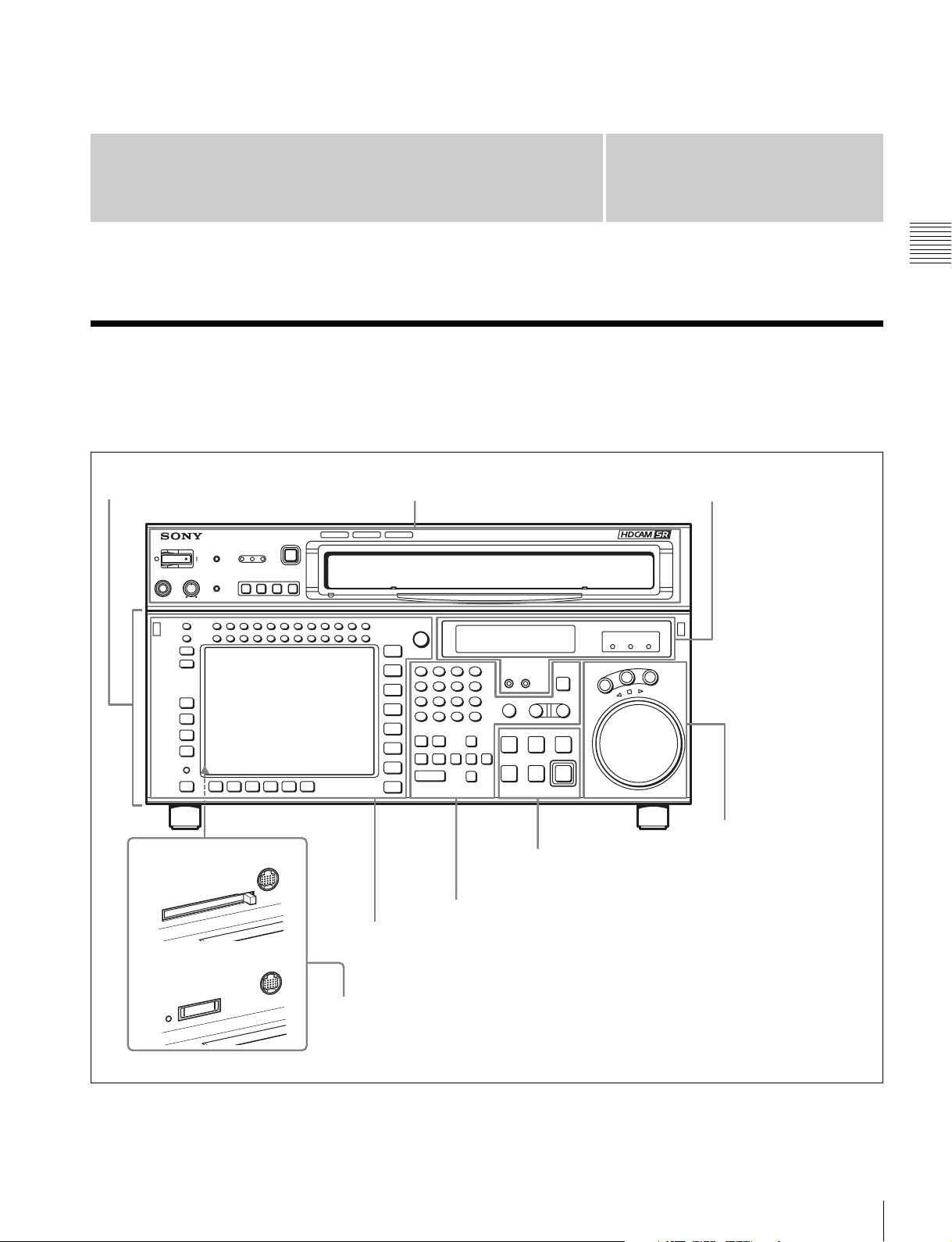
2-1 Control Panel
The control panel consists of the following sections:
• Upper control panel
Lower control panel
Upper control panel
Chapter
• Lower control panel
• System set-up panel
2
Chapter 2 Locations and Functions of Parts
4 Display section
(see page 20)
Serial number: lower
than 11001
Serial number: 11001
or higher
5 Search control section
(see page 22)
3 Tape transport control section
(see page 20)
2 Editing control section (see page 19)
1 Menu control section (see page 17)
System set-up panel: Access by opening the lower control panel (see page 23)
2-1 Control Panel
15
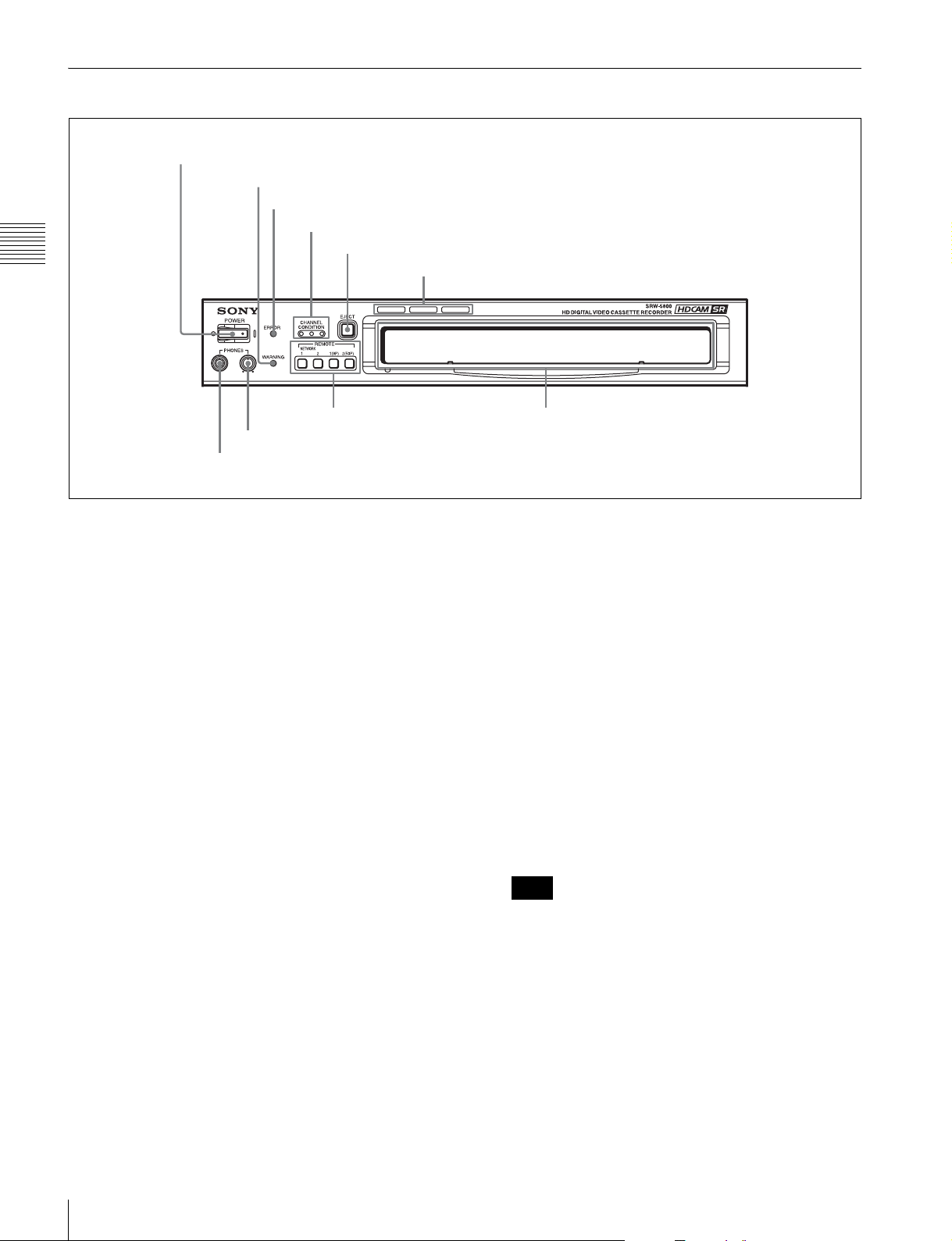
2-1-1 Upper Control Panel
1 POWER switch
2 WARNING indicator
3 ERROR indicator
Chapter 2 Locations and Functions of Parts
4 CHANNEL CONDITION indicators
5 EJECT button
6 Format indicators
7 REMOTE buttons
8 PHONES level control
9 PHONES jack
a POWER switch
Pressing on the ‘(’ side of this switch powers the unit and
lights up the information display (see page 20) and color
display (see page 17). To turn the unit off, press on the ‘a’
side of the switch.
b WARNING indicator
This lights when there is a fault in the unit. You can check
the details on the lower control panel.
For details, see “Error Messages/Warning Messages/
Condition Messages” on page 149.
c ERROR indicator
This lights when a serious problem occurs, such as an
operational malfunction or system internal error.
You can check the details on the lower control panel.
For details, see “Error Messages/Warning Messages/
Condition Messages” on page 149.
Cassette compartment
e EJECT button
Pressing this button automatically ejects the cassette after
several seconds.
f Format indicators (Digital BETACAM/HDCAM/
HDCAM SR)
These show the format of the cassette loaded into the unit.
g REMOTE buttons
Press one of the following buttons, to select how the VTR
is controlled.
NETWORK 1: This button lights when pressed, enabling
access from the network connected to the
NETWORK 1 connector on this unit.
NETWORK 2: This button lights up when pressed,
enabling file transfers between the VTR and the
shared file server, and control of the VTR from the
web client.
Note
d CHANNEL CONDITION indicators
These show the status of the playback signal.
Blue: The playback signal status is satisfactory.
Yellow: The playback signal is somewhat degraded, but
playback is possible.
However, if this indicator remains lit continuously,
head cleaning is required.
Red: The playback signal has deteriorated.
If this indicator remains lit continuously, head
cleaning or internal inspection is required.
16
2-1 Control Panel
This button operates only when the optional HKSR-
5804 Network Interface Board is installed.
1(9P): This button lights when pressed, enabling this unit
to be controlled from a device connected to the
REMOTE 1-IN(9P) connector or REMOTE 1-I/
O(9P) connector.
2(50P): This button lights when pressed, enabling this unit
to be controlled from a device connected to the
REMOTE 2 PARALLEL I/O(50P) connector.
Note
When the VTR is being controlled by the external
equipment connected to the REMOTE 1-IN(9P) or
REMOTE 2 PARALLEL I/O(50P) connector, all tape
transport buttons and edit operation buttons are disabled,
except the STOP and EJECT buttons. You may also
specify the disabling or enabling of all buttons by setting
the VTR SETUP menu item 008 “LOCAL FUNCTION
ENABLE”.
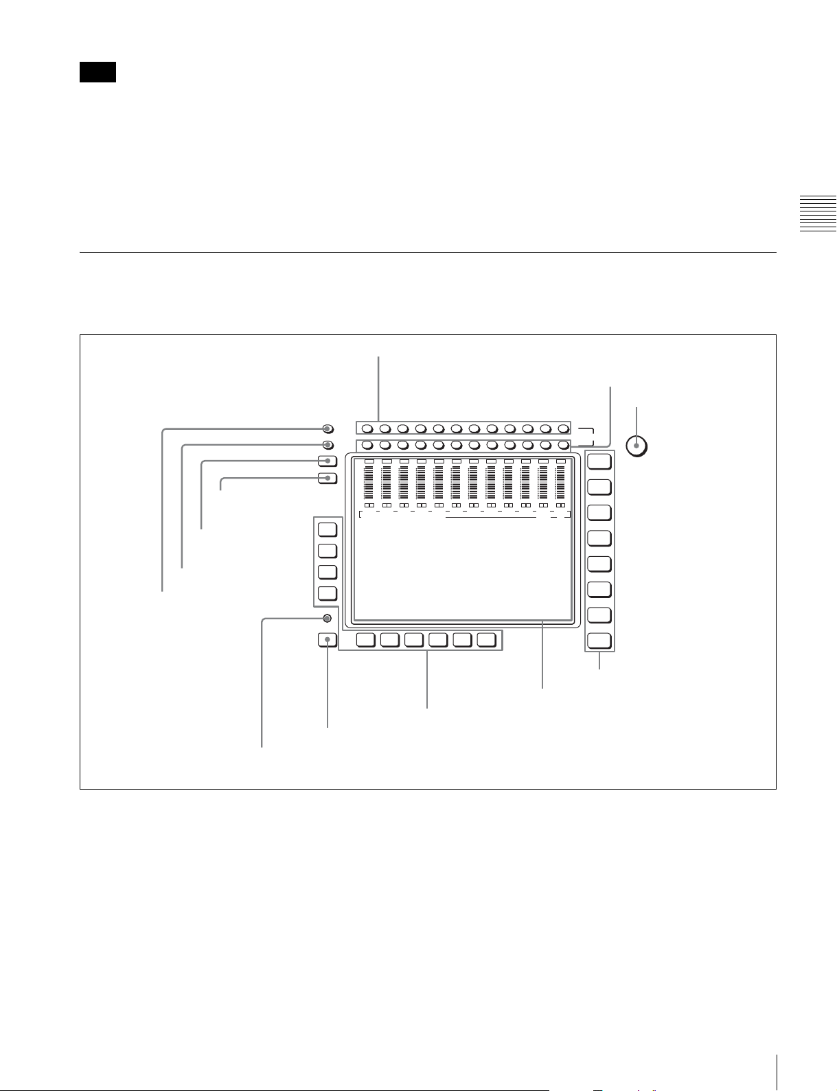
2-1-2 Lower Control Panel
1 Menu control section
1 MONITOR L buttons
OVER
OVER
dB
dB
dB
0
0
0
-10
-10
-10
-20
-20
-20
-30
-30
-30
-40
-40
DIAG
-40
LR
LR
CH1
CH2
CH3
EDIT PRESET VIDEO TC
F1
F2
F3
F4
9 DISPLAY button
0 FULL/FINE button
qa PB LEVEL button
qs REC LEVEL button
h PHONES level control
Adjusts the output level to the PHONES jack.
For details, see “5-1-2 Selecting Audio Signals” on
page 118.
i PHONES jack
Connect stereo headphones for audio monitoring during
recording, playback, and editing. Adjust the headphone
output level with the PHONES level control.
2 MONITOR R buttons
3 MULTI CONTROL knob
HOME
TC
VIDEO
AUDIO
CUE
PF1
PF2
MULTI
CONTROL
L
CH12CH11CH10CH9CH8CH7CH6CH5CH4CH3CH2CH1
MONITOR
R
OVER
OVER
OVER
OVER
OVER
OVER
OVER
OVER
OVER
dB
dB
dB
dB
dB
dB
0
0
0
-10
-20
-30
-40
LR
LR
CH4
0
-10
-10
-10
-20
-20
-20
-30
-30
-30
-40
-40
-40
LR
LR
LR
CH5
CH6
CH7
dB
0
0
-10
-10
-10
-20
-20
-20
-30
-30
-30
-40
-40
-40
LR
LR
CH8
CH9
0
LR
CH10
OVER
dB
dB
0
0
-10
-10
-20
-20
-30
-30
-40
-40
LR
LR
CH11
CH12
Chapter 2 Locations and Functions of Parts
F5ALT F6 F7 F8 F9 F10
7 ALT button
8 DIAG button
a MONITOR L buttons
Select the audio signal output from the MONITOR
OUTPUT L connector. This assigns the desired channel to
the MONITOR OUTPUT L connector. If you assign more
than one channel to the same monitor output connector, a
mixed audio signal is output.
You can also make this setting using the VTR SETUP
menu item 807 “AUDIO MONITOR-L select”.
In the audio playback level adjustment mode, this is used
to select the channel to be adjusted.
SET UP
4 Menu selection buttons
5 Color display
6 Function buttons
b MONITOR R buttons
Select the audio signal output from the MONITOR
OUTPUT R connector. This assigns the desired channel to
the MONITOR OUTPUT R connector. If you assign more
than one channel to the same monitor output connector, a
mixed audio signal is output.
You can also make this setting using the VTR SETUP
menu item 808 “AUDIO MONITOR-R select”.
In the audio playback level adjustment mode, this is used
to select the channel to be adjusted.
2-1 Control Panel
17

c MULTI CONTROL knob
Used to set the audio recording/playback level and make
settings in the SET UP menu (see page 112).
circuitry, and not through the magnetic conversion system comprising tape
and heads.
Note on faulty pixels on the LCD panel
d Menu selection buttons
These select the menu screen displayed on the display.
HOME button: Press this to go to the HOME menu
screen. The home menu provides settings for the basic
VTR operations and editing operations.
TC button: Press this to go to the TC (time code) menu
Chapter 2 Locations and Functions of Parts
screen. In the time code menu, you can switch LTC/
VITC, switch DF/NDF, set the time code to be
displayed on an external monitor, and so on.
VIDEO button: Press this to go to the VIDEO menu
screen. Use it to make video related settings.
AUDIO button: Press this to go to the AUDIO menu
screen. Use it to make audio related settings.
CUE button: Press this to go to the CUE menu screen.
The cue menu provides 10 pages to set cue points.
You can set up to 10 cue points per page. You can also
make settings for the Tele-File memory label system.
PF1 button: Press this to go to the PF1 (personal function
1) menu screen. You can register frequently-used
items in the PF1 menu. The factory default setting is
blank.
PF2 button: Press this to go to the PF2 (personal function
2) menu screen. You can register frequently-used
items in the PF2 menu. The factory default setting is
blank.
SET UP button: Press this to go to the SET UP menu
screen. The setup menu provides functions to save
menu settings in VTR banks or save to a “Memory
Stick”, registration operations in the PF buttons, VTR
SETUP menu settings, and so on.
For details of menus, see Chapter 4 “Menu Settings” on
page 38.
The LCD panel fitted to this unit is manufactured with
high precision technology, giving a functioning pixel
ratio of at least 99.99%. Thus a very small proportion of
pixels maybe “stuck”, either always off (black), always
on (red, green, or blue), or flashing. In addition, over a
long period of use, because of the physical characteristics
of the liquid crystal display, such “stuck” pixels may
appear spontaneously. These problems are not a
malfunction. Note that any such problems have no effect
on recorded data.
f Function buttons
Activates the functions in each menu.
g ALT (alternative) button
Press to change the items displayed on the current menu.
Press again to return to the original items.
h DIAG (diagnostic) button
Hold down the SFT button (see page 19) in the editing
control section and press this switch to switch to the DIAG
menu.
i DISPLAY button
This displays the down-converted output signal in the
whole color display.
Notes
• Depending on the system settings, it may not be possible
to output some signals.
• This function is for a quick check of the output signal,
and cannot be used as a monitor.
e Color display
This comprises principally the audio level display and
menu display.
Audio Level display:
In E-E mode
1)
, this displays the audio recording levels.
In playback mode, this displays the playback levels.
The display mode can be changed with the FULL/FINE
button. The factory default display is a reference level of
–20 dB, and peak level 0 dB.
Menu display:
This displays the menu screen selected by the menu
selection buttons.
Each menu screen shows the functions assigned to the
function buttons ([F1] to [F10]), and shows simultaneously
information required for time code display settings and so
on.
1) E-E mode
An abbreviation fo r Electric-to-Electric mode. In t his mode, video o r audio
input signals are passed and output only through the VTR’s internal
18
2-1 Control Panel
j FULL/FINE button
This selects the audio level meter display range.
FULL: The audio level meter display is from –60 dB to 0
dB, or –40 dB to +20 dB. Select which of these ranges
(peak level: 0 dB or +20 dB) is displayed in the VTR
SETUP menu item 814 “LEVEL METER SCALE”.
FINE: The audio level meter display range is expanded,
and displayed with a scale in steps of 0.25 dB. The
reference marker LED at the center of the level meter
display range lights. When the audio level exceeds the
maximum display range, the top OVER display
flashes. When under the minimum display range, the
bottom line flashes.
k PB (playback) LEVEL button
Press this button to enter the playback audio level
adjustment mode. In this mode, you can use the
MONITOR R button to select the adjustment target
channels from channels 1 to 12. While watching the audio
level meter, turn the MULTI CONTROL knob for a
desired audio level.
Clicking the MULTI CONTROL knob resets the playback
audio level to the factory set level (a reference level of –20
dB is set for a +4 dBm input). Clicking the MULTI
CONTROL knob again restores the adjusted level.
Press this button again to exit from the playback audio
level adjustment mode, and the MONITOR L and R
buttons return to the normal status (this status is called the
“MONITOR SELECT mode”).
l REC (recording) LEVEL button
Press this button to enter the recording audio level
adjustment mode. In this mode, you can use the
MONITOR L button to select the adjustment target
channels from channels 1 to 12. While watching the audio
level meter, turn the MULTI CONTROL knob for a
desired audio level.
Clicking the MULTI CONTROL knob resets the recording
audio level to the factory set level (a reference level of –20
dB is set for a +4 dBm input). Clicking the MULTI
CONTROL knob again restores the adjusted level.
Press this button again to exit from the recording audio
level adjustment mode, and the MONITOR L and R
buttons return to the normal status (this status is called the
“MONITOR SELECT mode”).
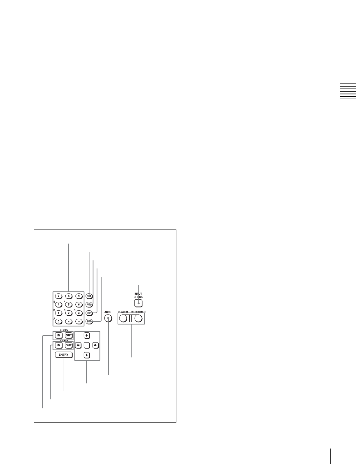
2 Editing control section
a Numeric buttons and +/– buttons
Press to input time data or edit points data at the cursor
position in menu display. Press buttons 0 to 5 while
holding down the SFT button to input hexadecimal A to F
for user bits. Use the +/– buttons to increase or decrease
settings.
b SFT (shift) button
Press buttons 0 to 5 while holding down this button to
input hexadecimal A to F for user bits.
Use also in combination with other buttons to perform
other operations.
c RCL (recall) button
Press to recall the previous setting, etc.
d CLR (clear) button
Press to clear input data.
e SET button
Press to finalize input data.
f INPUT CHECK button
While you hold down this button, the input signal is output
from the monitor output connector, so that you can monitor
the input video and audio.
When the LTC/VITC time code is shown on the display,
you can check the time code generator.
Chapter 2 Locations and Functions of Parts
1 Numeric buttons and +/– buttons
2 SFT button
3 RCL button
4 CLR button
5 SET button
8 AUTO button
9 Cursor buttons
0 ENTRY button
qa IN/OUT buttons
qs AUDIO IN/AUDIO OUT buttons
6 INPUT CHECK
button
7 PLAYER/
RECORDER
buttons
g PLAYER/RECORDER buttons
Select which VTR is to be controlled by this VTR’s control
panel during editing when this VTR is used as a recorder
and an external VTR is connected to the REMOTE 1IN(9P) or REMOTE 1-I/O(9P) connector as a player.
PLAYER: The tape transport buttons and editing
operation buttons on the control panel control the
external player VTR.
RECORDER: The tape transport buttons and editing
operation buttons on the control panel control the
recorder VTR (this VTR).
The PLAYER/RECORDER buttons have no effect when
using this VTR alone.
h AUTO button
When this button is pressed, it lights up and auto edit mode
is activated.
i Cursor buttons
Use to move the cursor (shown in reverse video) on the
display. Also use to change menu settings.
j ENTRY button
Press to enter an edit or cue point.
While holding down this button, press either the AUDIO
IN or AUDIO OUT button, or the IN or OUT button.
2-1 Control Panel
19
k IN/OUT buttons
To set a IN or OUT point during editing, press either of
these buttons while holding down the ENTRY button.
l AUDIO IN/AUDIO OUT buttons
To set an AUDIO IN or AUDIO OUT point during insert
editing, press either of these buttons while holding down
the ENTRY button.
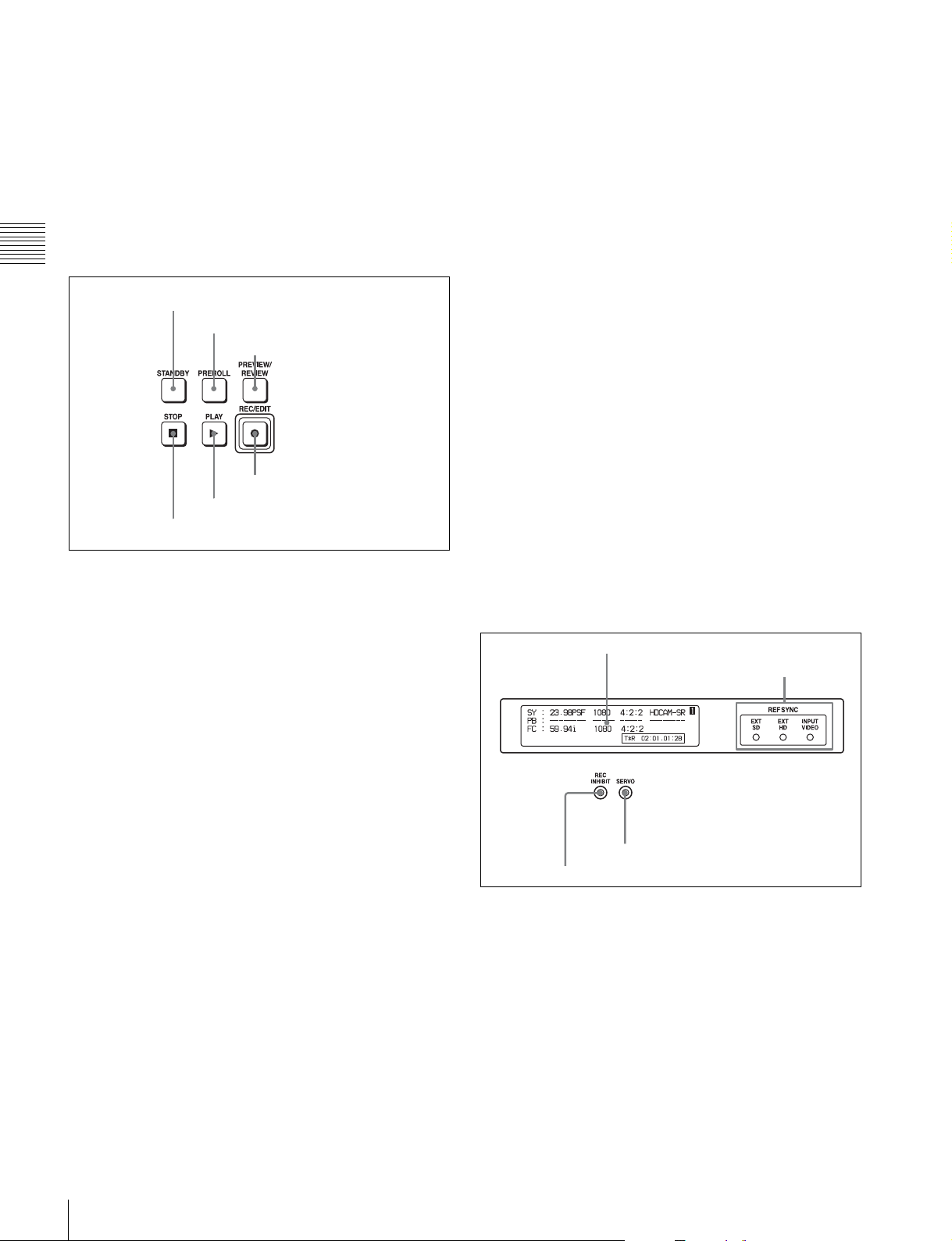
3 Tape transport control section
Chapter 2 Locations and Functions of Parts
1 STANDBY button
2 PREROLL button
3 PREVIEW/REVIEW button
4 REC/EDIT button
5 PLAY button
6 STOP button
a STANDBY button
Press this button in other than standby mode to make it
light up and place the VTR in standby mode. The head
drum rotates in standby mode, thereby shortening the time
required for the tape to start.
Press this button while in standby mode to turn the button
off and exit from standby mode. The head drum stops
rotating and the tape tension is released. If the VTR
remains in standby mode for more than eight minutes
(factory setting), standby mode is automatically canceled
in order to safeguard the tape.
d REC/EDIT (recording/edit) button
Press this button while holding down the PLAY button to
start recording.
If you press this button in play mode, manual editing
begins. After setting edit points, if you press this button
while the AUTO button is lit, automatic editing is
performed.
e PLAY button
Press to start playback.
Press this button while holding down the REC/EDIT
button to start recording.
f STOP button
Press this button to stop recording or playback.
When you insert the cassette, the VTR automatically
enters STBY OFF mode.
The STOP button flashes in the following cases.
•The [F2] (SERVO REF) button in the PF1 menu is set to
“input” but there is no video input signal.
•The [F2] (SERVO REF) button in the PF1 menu is set to
“ext” but there is no external reference video signal.
• The input signal is out of synchronization with the
external reference video signal.
You can change the setting of the VTR SETUP menu item
102 “REFERENCE SYSTEM ALARM” so that the STOP
button will not flash in these cases.
4 Display section
1 Information display
2 REF SYNC indicators
b PREROLL button
Press to run the tape to the preroll point (a position factory
set to five seconds before the IN point).
Press this button while holding down the IN, OUT,
AUDIO IN or AUDIO OUT button to cue up the tape at the
corresponding edit point.
For details on changing the preroll time, see “4-2-5
Setting the Preroll Time (PREROLL TIME)” on page 63.
c PREVIEW/REVIEW button
After the edit points are set, press this button to preview,
on the monitor connected to the recorder, the effect of the
edit before it is performed. In this operation, the tape runs,
but no editing is carried out.
If you press this button after carrying out an edit, the
results of the edit are played back on the monitor
connected to the recorder.
20
2-1 Control Panel
3 SERVO indicator
4 REC INHIBIT indicator
a Information display
The information display shows a number of different
pages. To change the page displayed, with no other items
selected in the menu display (HOME, TC, VIDEO,
AUDIO, PF1, and PF2), turn the MULTI CONTROL knob
while holding it down.
The currently selected page number also appears at the
upper right of the information display.
Each page can be set so that it is not displayed in the INFO
SELECT menu under the OTHERS CHECK menu in the
MAINTENANCE menu.

For details, refer to the Maintenance Manual Volume 1.
Page 1: System status
SY: Shows the recording system information (signal
standard and tape format).
PB: Shows the information recorded on the tape (signal
standard and tape format) while being played back.
FC: Shows the converted signal standard when an HKSR-
5001 board is installed.
TC: Shows the time code.
Page 2: System status
ACTIVE LINE: Shows the status of 1080/1035
conversion active line.
1080t1080
1035t1080(PANEL)
1035t1080(CONV): Shows the current conversion
status.
- - - - -: Cannot be converted.
OFF: No conversion done.
DOWN CONV. OUTPUT: Shows the output status of the
down converter.
ACTIVE: Output.
MUTING: No output.
EOS: Appears at the location of the time code for the valid
end of the previous recording.
Page 3: Phase (OUTPUT)
HD SDI OUTPUT ADV.: Shows the phase of the main
line HD SDI output.
OFF: In phase with reference.
–90H: 90H (HD) advanced with respect to reference.
DOWN CONV. OUTPUT ADV.: Shows the phase of the
down converter output.
OFF: In phase with reference.
–2H: 2H (SD) advanced with respect to reference.
Page 4: Phase (AUDIO)
AUDIO PB OUTPUT ADV.: Shows the phase of the
audio output signal.
OFF: Output in phase with the video output signal.
–1Frame: Output one frame advanced with respect to
the video output signal.
AUDIO INPUT DELAY: Shows the recording phase of
the audio input signal.
OFF: Recorded in phase with the video output signal.
+1Frame: Recorded one frame delayed with respect to
the video input signal.
AES/EBU & MONITOR OUTPUT: Shows the phase of
the AES/EBU and MONITOR AUDIO outputs.
REF: Output in phase with reference.
FC: In phase with the FC output.
–90H(HD): 90H (HD) advanced with respect to
reference.
–2H(SD): 2H (SD) advanced with respect to
reference.
Page 5: Phase (TC)
TC INPUT DELAY: Shows the recording phase of the
input time code.
OFF: Recorded in phase with the input video signal.
+1Frame: Recorded one frame delayed with respect to
the input video signal.
LTC OUTPUT: Shows the phase of the output LTC.
LINE: Output in phase with the main line HD SDI
output.
FC: Output in phase with the FC output.
Page 6: Meta data
• HDCAM-SR
META DATA LINE(REC): Shows the status of the three
lines for metadata recording on this unit.
META DATA LINE(OUT): Shows the status of the three
lines of main HD SDI output into which metadata is
multiplexed.
META DATA LINE(FC): Shows the status of the three
lines of output from an HKSR-5001 board into which
metadata is multiplexed.
META DATA LINE(SD): Shows the status of the three
lines of SD SDI output into which metadata is
multiplexed.
• HDCAM
Shows the L1, L2, DID, and SDID readout from the tape.
The data for L1, L2, DID, and SDID are treated as one
packet and up to three packets are displayed at one time.
Page 7: 3G-SDI
HDSDI IN: Shows the 3G interface status of the main line
HD SDI input.
HDSDI OUT: Shows the 3G interface status of the main
line HD SDI output.
MON OUT: Shows the 3G interface status of the main
line HD SDI monitor output.
FC OUT: Shows the 3G interface status of the format
converter output when an HKSR-5001 board is
installed.
AUX OUT: Shows the 3G output interface status of the
AUX OUTPUT A/B connectors when an HKSR5804 board is installed.
Page 8: Select FPS
TAPE FORMAT: Shows the playback format of the tape.
ACTUAL FORMAT: Shows the recording format of the
tape recorded with frames per second (Select FPS
mode) specified.
Select FPS: Shows the transportation speed and playback
speed of the tape recorded with Select FPS mode
specified.
Page 10: VPID
Shows the VPID
1)
multiplexed with the input signal
for LINK-A and LINK-B.
1) VPID
A packet standard defined by SMPTE-352M that identifies the format of
multiplexed signals on the SDI.
Chapter 2 Locations and Functions of Parts
2-1 Control Panel
21
Note
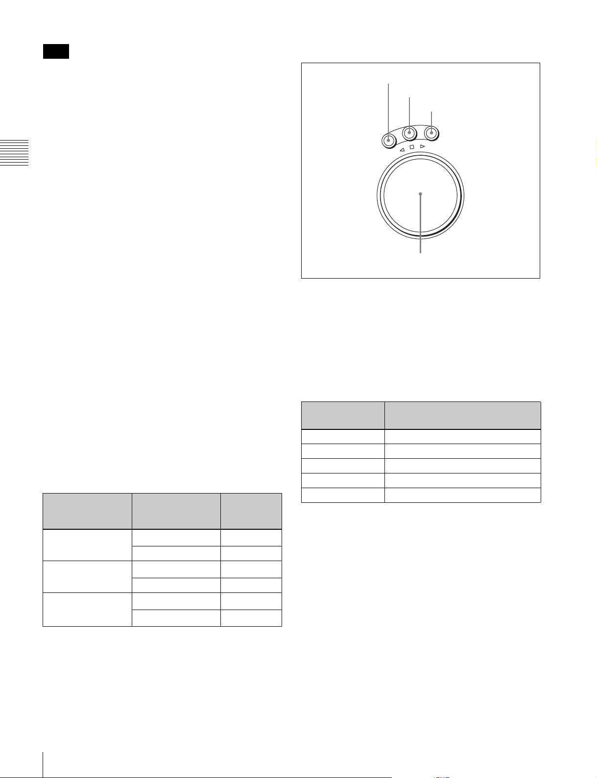
5 Search control section
The ACTIVE LINE setting displayed on page 2 can be
made in the SYSTEM menu under the OTHERS CHECK
menu in the MAINTENANCE menu. The phase settings
displayed on pages 3 to 5 and the settings relating to
META DATA recording displayed on page 6 can be made
in the PHASE SET/META DATA menu under the
ALT+OTHERS CHECK menu in the MAINTENANCE
menu.
Chapter 2 Locations and Functions of Parts
For details, refer to the Installation Manual.
b REF SYNC (reference signal) indicators
These indicate the signal selected as the reference signal.
If there is no reference signal input to the selected
connector, the STOP button flashes.
EXT SD: Lights when “extern SD” is selected by the VTR
SETUP menu item 006 “EXTERNAL REFERENCE
select”.
EXT HD: Lights when “extern HD” is selected by the
VTR SETUP menu item 006 “EXTERNAL
REFERENCE select”.
INPUT VIDEO: Lights when “INPUT” is selected by the
VTR SETUP menu item 005 “SERVO/AV
REFERENCE select”.
c SERVO indicator
Lights up when the drum servo and capstan servo are
locked.
1 SHUTTLE button
2 JOG button
3 VAR button
V
G
A
O
J
E
L
T
T
U
H
S
E
S
R
E
V
E
R
R
F
O
R
W
A
R
D
4 Search dial
a SHUTTLE button
Press to enter shuttle mode. In this mode, the button lights
and playback at the speed corresponding to the angle of
rotation of the search dial is possible. The playback speed
range depends on the frame frequency of the unit. In this
mode, the search dial clicks at the positions for 0 (still
picture) and ±10 times normal playback speed (HDCAM/
Digital Betacam) or ±8 times normal playback speed
(HDCAM-SR).
d REC INHIBIT indicator
Only when this indicator is not lit, you can make settings
for assemble/insert editing mode, and carry out recording
and playback operations.
The status of this indicator depends on the setting of the
[F2] (REC INH) button in the HOME menu and the state
of the record-protect plug on the cassette.
Setting of the [F2]
(REC INH) button in
the HOME menu
State of the recordprotect plug on the
cassette
all Recording disabled
Recording allowed Lit
crash REC, video/
CTL, audio/CTL
Recording disabled
Recording allowed Unlit
off Recording disabled
Recording allowed
a) Toggling between lit/flashing settings is possible using the VTR SETUP
menu item 104 “REC INHIBIT LAMP FLASHING”.
REC INHIBIT
indicator
Lit/flashing
Lit/flashing
Lit/flashing
Unlit
a)
a)
a)
a)
Frame frequency
Playback speed range (for
HDCAM-SR format)
23.98/24 Hz ±50 times normal playback speed
25 Hz ±48 times normal playback speed
29.97/30 Hz ±40 times normal playback speed
50 Hz ±24 times normal playback speed
59.94/60 Hz ±20 times normal playback speed
b JOG button
Press to select jog mode. In this mode, the button lights up
and playback is possible at –1 to +1 times normal speed, ±2
times normal speed (HDCAM/HDCAM-SR), or ±3 times
normal speed (Digital Betacam) (determined by the setting
in the VTR SETUP menu item 107 “JOG DIAL
RESPONSE”). In this mode, the search dial does not click.
c VAR (variable) button
Press to select variable speed playback mode for noiseless
playback in the range from –0.5 to +1 times normal speed
(HDCAM-SR), from –1 to +2 times normal speed
(HDCAM), or from –1 to +3 times normal speed (Digital
Betacam). Playback exceeding this speed range is not
possible. The search dial clicks at the positions for stillpicture and normal playback speed.
22
2-1 Control Panel

d Search dial
Rotate to search for edit points. Rotate the dial clockwise
for forward playback (the B indicator lights up) or
counterclockwise for reverse playback (the b indicator
lights up). The x indicator lights up while the VTR is in
stop mode.
Shuttle mode: The playback speed corresponds to the
angle of rotation of the search dial. The playback
speed range depends on the frame frequency of the
unit. (See item 1 SHUTTLE button.) The dial clicks
at the positions for 0 (still picture) and ±10 times
normal playback speed (HDCAM/Digital Betacam)
or ±8 times normal playback speed (HDCAM-SR).
Jog mode: The playback speed corresponds to the
rotational speed of the dial (–1 to +1 times normal
2-1-3 System Set-Up Panel
Lift the lower control panel up to its horizontal position to
access the system set-up panel.
For details of opening and closing the control panel, refer
to the Maintenance Manual.
speed, ±2 times normal speed (HDCAM/HDCAMSR), or ±3 times normal speed (Digital Betacam))
depending on the setting of the VTR SETUP menu
item 107 “JOG DIAL RESPONSE”). The dial does
not click.
Variable speed playback mode: Noiseless playback is
possible in the range from –0.5 to +1 times normal
speed (HDCAM-SR), from –1 to +2 times normal
speed (HDCAM), or from –1 to +3 times normal
speed (Digital Betacam). The speed settings can be
changed using the menu. The dial clicks at the
positions for still-picture and normal playback speed.
Capstan override mode: Rotating the dial while holding
down the PLAY button changes the playback speed
by up to ±15%.
Chapter 2 Locations and Functions of Parts
CONTROL PANEL connector
Serial number: lower than 11001 Serial number: 11001 or higher
Card slot eject button
PCMCIA card slot
For details, see “3-4 Using a “Memory Stick”” on
page 36.
“Memory Stick” slot
Access indicator
2-1 Control Panel
23

2-2 Connector Panel
1 ANALOG I/O section (see page 25)
Chapter 2 Locations and Functions of Parts
3 Remote input/output section
(see page 28)
2 DIGITAL I/O section (see page 27)
4 Power supply
(see page 28)
24
2-2 Connector Panel
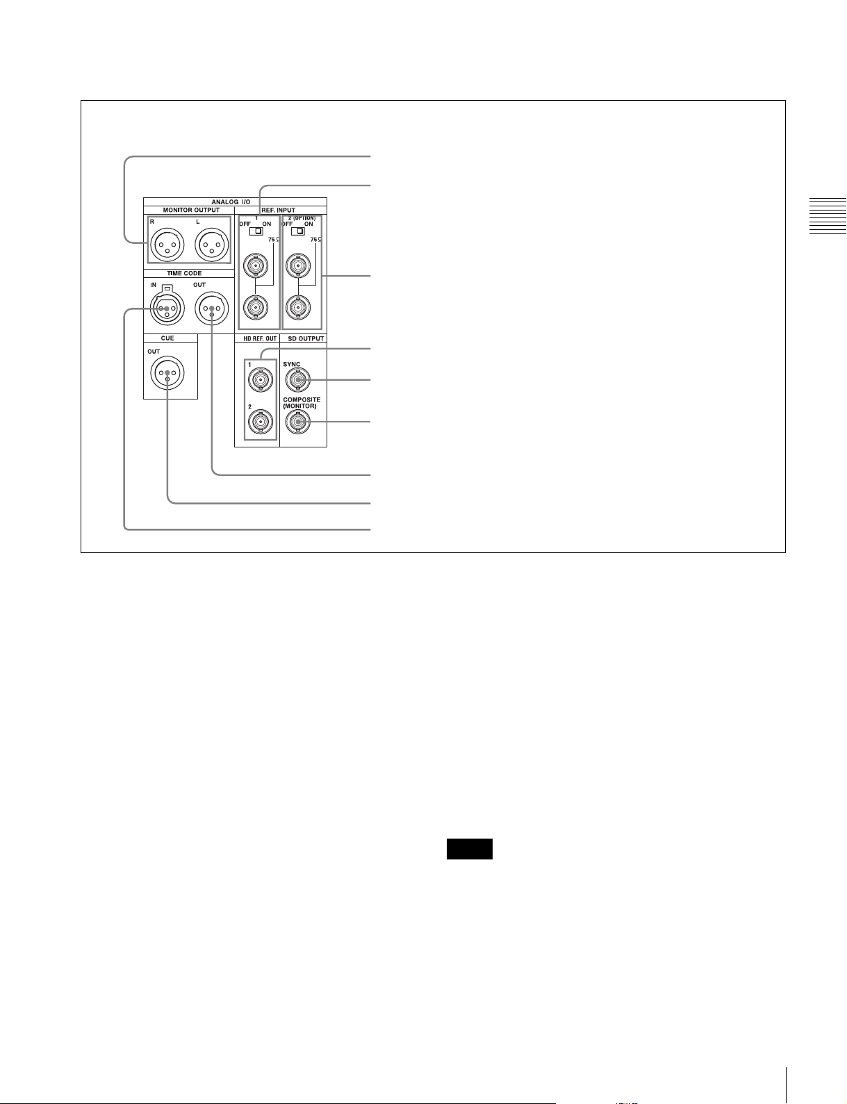
1 ANALOG I/O (input/output) section
4 HD REF. OUT connectors
1 MONITOR OUTPUT L/R connectors
2 REF. INPUT 1 connectors and 75Ω termination switch
Chapter 2 Locations and Functions of Parts
3 REF. INPUT 2 connectors and 75Ω termination switch
5 SD OUT SYNC connector
6 SD OUT COMPOSITE (MONITOR) connector
7 TIME CODE OUT connector
8 CUE OUT connector
9 TIME CODE IN connector
a MONITOR OUTPUT L/R connectors
(XLR-3-31, male)
These output the audio signals for monitoring L and R
channels. To select the signals to output, use the
MONITOR L and MONITOR R buttons on the lower
control panel.
For details, see “5-1-2 Selecting Audio Signals” on
page 118.
b REF. INPUT 1 connectors (BNC) and 75Ω
termination switch
Input a reference video signal of the selected field
frequency. Select HD or SD with the VTR SETUP menu
item 006 “EXTERNAL REFERENCE select”. When HD
is selected, input a tri-level SYNC signal. When SD is
selected, input a video signal with chroma burst (VBS) or
a monochrome video signal (VS).
A loop-through connection is possible. Set the 75Ω
termination switch to OFF if you are using a loop-through
connection and set it to ON if you are not using a loopthrough connection.
c REF. INPUT 2 connectors (BNC) and 75Ω
termination switch
Input a reference video signal of the field frequency
selected for the format converter output. Select HD or SD
with the VTR SETUP menu item A08 “FC REFERENCE
select”. When HD is selected, input an HD tri-level SYNC
signal for external synchronization. When SD is selected,
input a video signal with chroma burst (VBS) or a
monochrome video signal (VS). A loop-through
connection is possible. Set the 75Ω termination switch to
OFF if you are using a loop-through connection and set it
to ON if you are not using a loop-through connection.
d HD REF. OUT connectors (BNC)
Output an HD tri-level sync signal during tape playback.
Notes
• When the system is operated in 4:2:2/720P mode, no
signal is output from these connectors.
• When the system is operated in 4:2:2/1080/50P, 4:2:2/
1080/59.94P, or 4:2:2/1080/60P mode, the reference
signal that is identical to interlace signal is output from
these connectors.
2-2 Connector Panel
25

e SD OUT SYNC connector (BNC)
This outputs an NTSC or PAL signal for external
synchronization.
Note
The output phase is the same as that of the composite
signal output from the SD OUT COMPOSITE
(MONITOR) connector.
Because the output phase changes with the operation mode
of the VTR, use this for synchronization with the video
Chapter 2 Locations and Functions of Parts
monitor.
f SD OUT COMPOSITE (MONITOR) connector
(BNC)
Outputs an analog composite signal for a video monitor.
When the ALT/[F6] (CHARA SUPER) setting in the TC
menu is on, character signals such as time codes are
superimposed on the output.
g TIME CODE OUT connector (XLR 3-31, male)
Outputs the following time codes according to the VTR
operation mode.
In playback mode: Playback time code
In recording mode: Time code generated by the internal
time code generator, or time code input to the TIME
CODE IN connector.
i TIME CODE IN connector (XLR 3-32, female)
Accepts external time code for recording to tape. Connect
to the time code output connector of the external
equipment.
To select the output signal, use the VTR SETUP menu
item 613 “TC OUTPUT SIGNAL IN REGENE MODE.”
Setting Description
off tape In playback mode, playback time code signal
is output. In recording mode, TCG time code
signal is output.
regene Only when the servo is locked in playback
through The time code signal from the TIME CODE IN
mode, playback time code signal is
regenerated and output. In all other cases,
output is the same as for the “off tape” setting.
connector is output as it is. (Used for cascade
connections.)
(For more information about cascade
connections, see “3-1-3 Cascade
Connection” on page 31.)
h CUE OUT (cue output) connector
(XLR 3-31, male)
Outputs cue track audio during HDCAM or Digital
Betacam playback.
Note
There is no cue track on an HDCAM-SR tape, and
therefore no output.
26
2-2 Connector Panel
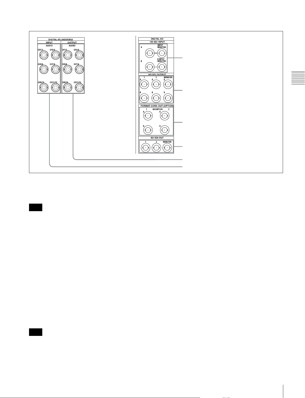
2 DIGITAL I/O (input/output) section
1 HD SDI INPUT A/B connectors
Chapter 2 Locations and Functions of Parts
2 HD SDI OUTPUT A/B connectors
3 FORMAT CONV. OUT (OPTION) A/B connectors
4 SD SDI OUT 1/2/MONITOR connectors
5 DIGITAL I/O (AES/EBU) OUTPUT connectors
6 DIGITAL I/O (AES/EBU) INPUT connectors
a HD SDI (SDI video/audio) INPUT A/B connectors
(BNC)
These accept SDI video/audio signals.
Note
The INPUT MONITOR connectors are for use with an
input monitor and does not follow the standards for output.
b HD SDI (SDI video/audio) OUTPUT A/B
connectors (BNC)
These output three sets of SDI video/audio signals.
When the ALT/[F6] (CHARA SUPER) buttons are set to
ON in the TC menu, time data or other text data is
superimposed on the signal output from the MONITOR
connector.
c FORMAT CONV. OUT (OPTION) A/B
connectors (BNC)
These output two sets of format-converted video/audio
signals.
When the ALT/[F5] (FC CHARA) buttons are set to ON in
the TC menu, the output has time data or other text
superimposed on the signal.
d SD SDI OUT 1/2/MONITOR connectors (BNC)
These output three sets of video/audio signals. When the
ALT/[F6] (CHARA SUPER) buttons are set to ON in the
TC menu, time data or other text data is superimposed on
the output from the MONITOR connector.
e DIGITAL I/O (AES/EBU) OUTPUT connectors
(BNC)
These output digital signals in AES/EBU format for
channels 1 to 12.
f DIGITAL I/O (AES/EBU) INPUT connectors
(BNC)
These accept digital signals in AES/EBU format for
channels 1 to 12.
Note
This is only valid when the optional HKSR-5001 format
converter board is installed.
2-2 Connector Panel
27
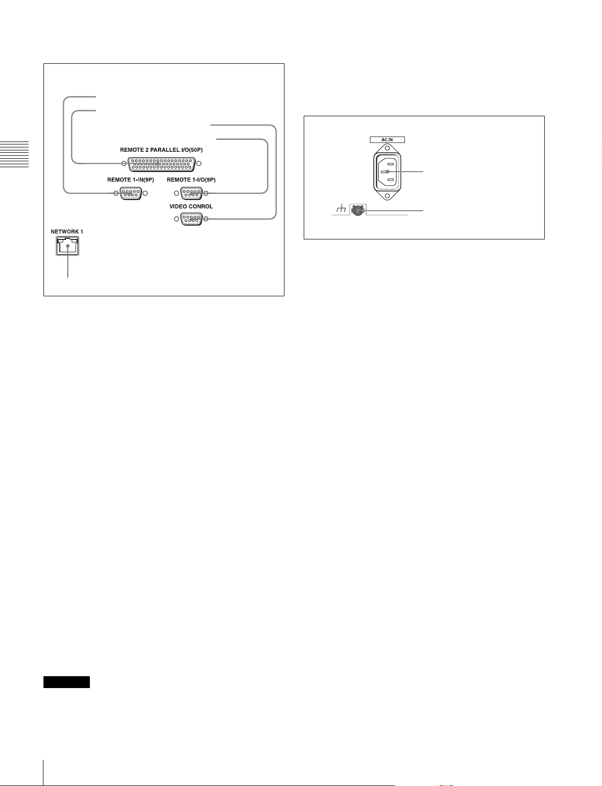
3 Remote input/output section
• When you connect the NETWORK cable of the unit to
peripheral device, use a shielded-type cable to prevent
malfunction due to radiation noise.
1 REMOTE1-IN(9P) connector
2 REMOTE 2 PARALLEL I/O(50P) connector
3 VIDEO CONTROL connector
4 REMOTE1-I/O(9P) connector
Chapter 2 Locations and Functions of Parts
5 NETWORK 1 connector
a REMOTE 1-IN(9P) connector (D-sub 9-pin,
female)
Use this, with the supplied 9-pin remote control cable, to
connect the unit to another SRW-5000/5500 unit or
another HD VTR unit to carry out editing with a BVEseries editor BVE-900/910/2000/9000/9100.
4 Power supply
1 AC IN connector
2 U Ground terminal
a AC IN connector
Connects to an AC outlet using an appropriate power cord.
b U Ground terminal
b REMOTE 2 PARALLEL I/O(50P) connector (D-
sub 50-pin, female)
Inputs an external remote control signal.
For details, refer to the Maintenance Manual Volume 1.
c VIDEO CONTROL (Digital Video Processor
Control) connector (D-sub 9-pin, female)
Connects to the optional HKDV-900 HD Digital Video
Controller to enable remote control of the internal digital
video processor. Turn off the power before connecting the
remote controller.
d REMOTE 1-I/O(9P) connector (D-sub 9-pin,
female)
Use this, with the supplied 9-pin remote control cable, to
connect the unit to another SRW-5000/5500 unit or
another HD VTR unit to carry out editing with a BVEseries editor BVE-700/2000/9000/9100.
e NETWORK 1 connector
Used for monitoring the VTR by SNMP, or for setting or
changing VTR settings by HTTP.
CAUTION
• For safety, do not connect the connector for peripheral
device wiring that might have excessive voltage to this
port. Follow the instructions for this port.
28
2-2 Connector Panel
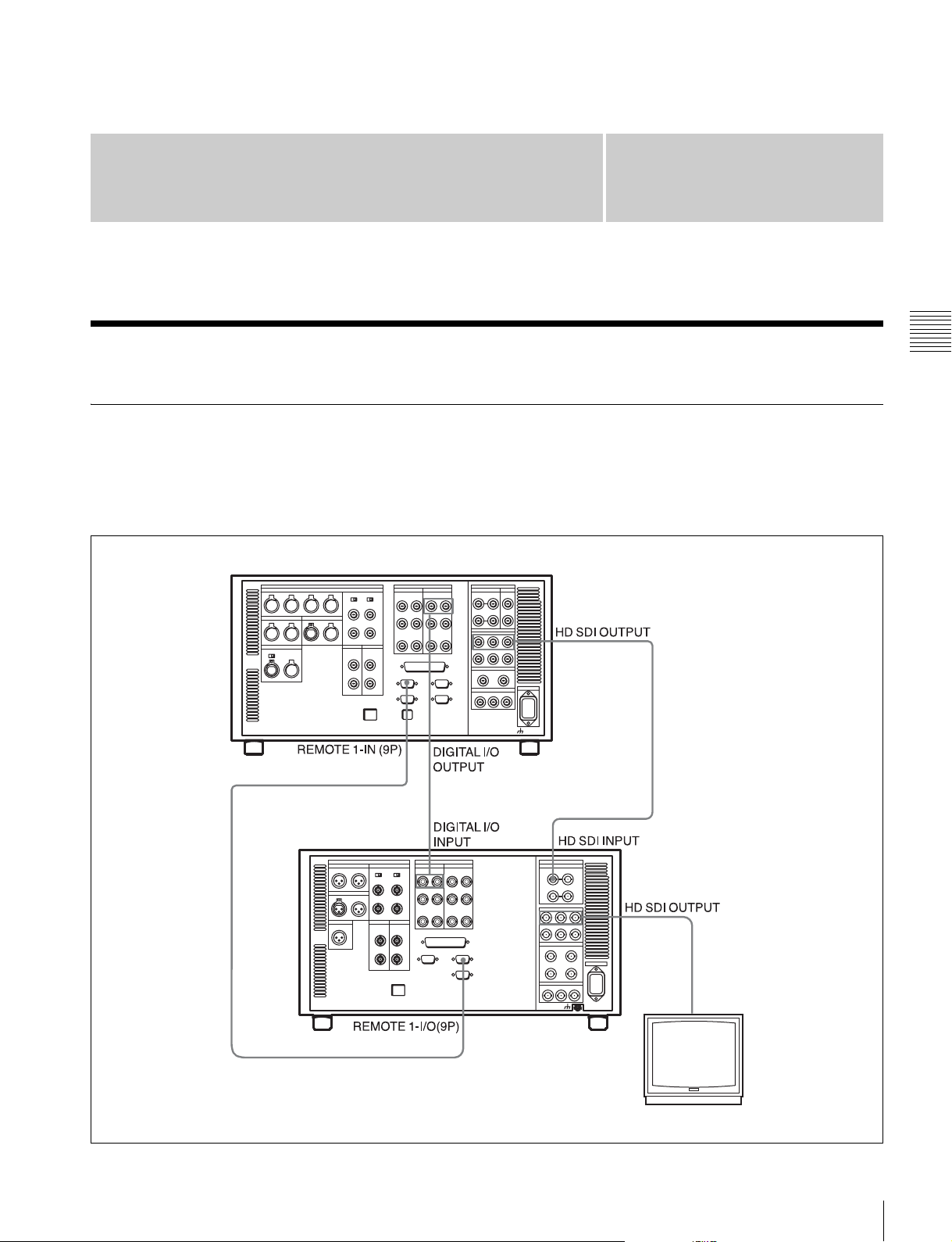
Setting Up the VTR
Chapter
3
3-1 Connecting External Equipment
3-1-1 Making HD Digital Connections
This example shows the connections when using an SRW5000/5500 as player and an SRW-5800 as recorder, in
59.94i or 60i mode.
SRW-5000/5500 (Player)
9-pin remote control cable
a)
Chapter 3 Setting Up the VTR
SRW-5800 (Recorder)
a) The figure shows the SRW-5500.
Video monitor
(HD serial monitor)
3-1 Connecting External Equipment
29
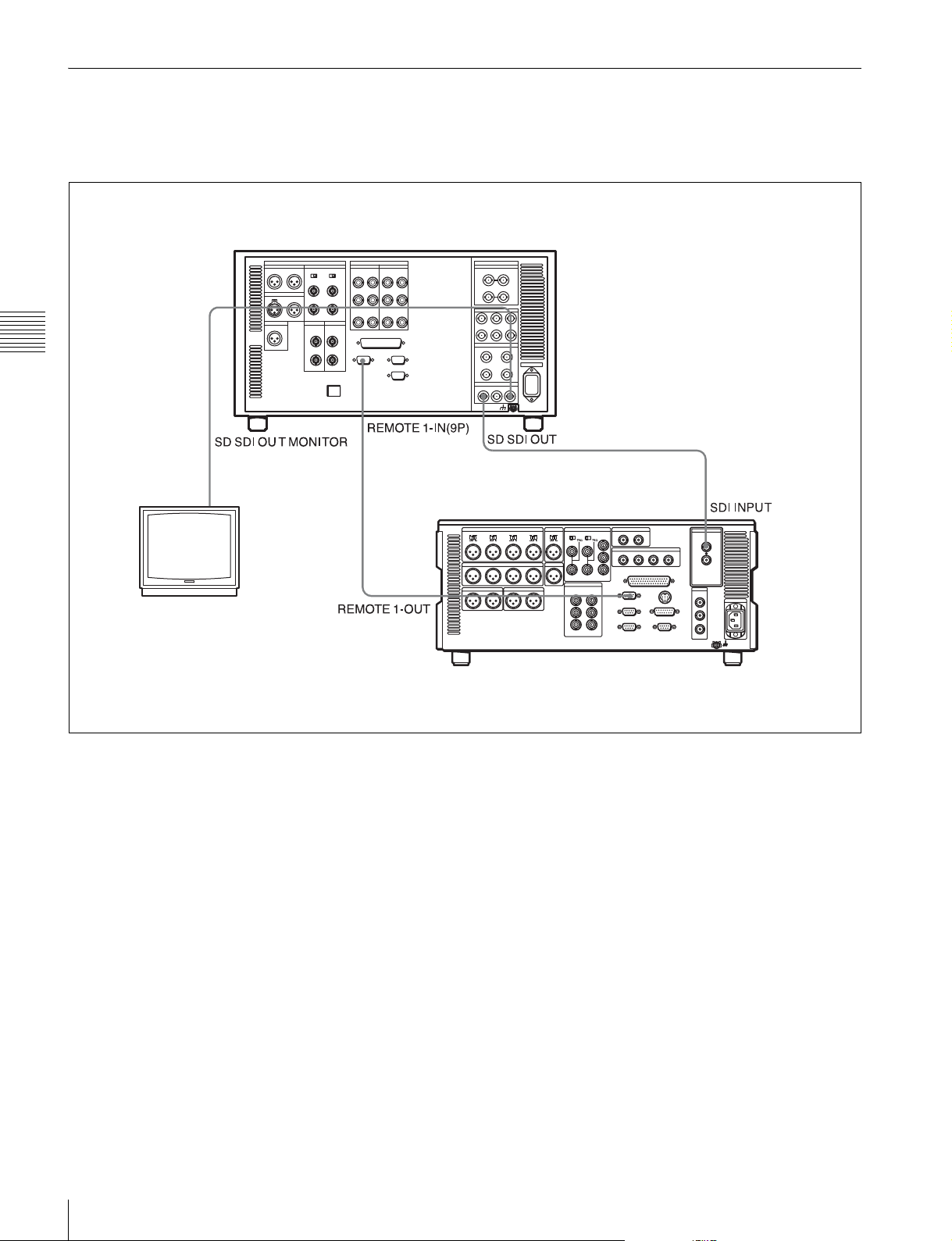
3-1-2 Making NTSC/PAL Digital Connections
This example shows how to connect two VTRs, an SRW5800 as the player and a DVW-2000 D-1 Component
Digital VTR as the recorder.
SRW-5800 (Player)
Chapter 3 Setting Up the VTR
BNC cable
Video monitor
(NTSC/PAL monitor)
BNC cable
DVW-2000 (Recorder)
9-pin remote
control cable
30
3-1 Connecting External Equipment
 Loading...