

Sony SRW-1, SRPC-1, HKSR-102, HKSR-103, HKSR-101 Operation Manual

HD PORTABLE DIGITAL RECORDER
SRW-1
HD VIDEO PROCESSOR
SRPC-1
OPTICAL INTERFACE UNIT
HKSR-101
PICTURE CACHE BOARD
HKSR-102
RGB 60P PROCESSOR BOARD
HKSR-103
OPERATION MANUAL [English]
1st Edition (Revised 7)
WARNING
To reduce the risk of fire or electric shock,
do not expose the apparatus to rain or
moisture.
generates, uses, and can radiate radio frequency energy and,
if not installed and used in accordance with the instruction
manual, may cause harmful interference to radio
communications. Operation of this equipment in a residential
area is likely to cause harmful interference in which case the
user will be required to correct the interference at his own
expense.
To avoid electrical shock, do not open the
cabinet. Refer servicing to qualified
personnel only.
For HKSR-101 only
This Optical Interface Unit is classified as a CLASS 1
LASER PRODUCT.
Laser diode properties
Wave length: 1310±20 nm
Emission duration: Continuous
Laser output power: 10 mW (max.)
Standard: IEC60825-1 (2001)
Laserdiode data
Bølgelængde: 1310±20 nm
Strålingsvarighed: Kontinuerlig
Lasereffekt: 10 mW (max.)
Standard: IEC60825-1 (2001)
Laserdiodens egenskaper
Våglängd: 1310±20 nm
Strålningstid: utan avbrott
Laseruteffekt: 10 mW (max.)
Standard: IEC60825-1 (2001)
Laserdiodens egenskaper
Bølgelengde: 1310±20 nm
Emisjonslengde: Kontinuerlig
Laser utgangseffekt: 10 mW (max.)
Standard: IEC60825-1 (2001)
You are cautioned that any changes or modifications not
expressly approved in this manual could void your authority to
operate this equipment.
All interface cables used to connect peripherals must be
shielded in order to comply with the limits for a digital device
pursuant to Subpart B of Part 15 of FCC Rules.
This device complies with Part 15 of the FCC Rules.
Operation is subject to the following two conditions: (1) this
device may not cause harmful interference, and (2) this
device must accept any interference received, including
interference that may cause undesired operation.
For customers in Canada (for SRW-1/SRPC-1/HKSR-101)
This Class A digital apparatus complies with Canadian
ICES-003.
For the customers in Europe
This product with the CE marking complies with the EMC
Directive issued by the Commission of the European
Community.
Compliance with this directive implies conformity to the
following European standards:
• EN55103-1 :Electromagnetic Interference(Emission)
• EN55103-2 : Electromagnetic Susceptibility(Immunity)
This product is intended for use in the following
Electromagnetic Environments: E1 (residential), E2
(commercial and light industrial), E3 (urban outdoors), E4
(controlled EMC environment, ex. TV studio).
The manufacturer of this product is Sony Corporation, 1-7-1
Konan, Minato-ku, Tokyo, Japan.
The Authorized Representative for EMC and product safety is
Sony Deutschland GmbH, Hedelfinger Strasse 61, 70327
Stuttgart, Germany.
For the customers in Taiwan only
CAUTION
The use of optical instruments with this product will
increase eye hazard.
Use of controls or adjustments or performance of
procedures other than those specified herein may result in
hazardous radiation exposure.
For the customers in the USA (for SRW-1/SRPC-1/HKSR-
101)
This equipment has been tested and found to comply with the
limits for a Class A digital device, pursuant to Part 15 of the
FCC Rules. These limits are designed to provide reasonable
protection against harmful interference when the equipment is
operated in a commercial environment. This equipment
2

VORSICHT
Um die Gefahr von Bränden oder
elektrischen Schlägen zu vermeiden, darf
dieses Gerät weder Regen oder
Feuchtigkeit ausgesetzt werden.
Um einen elektrishen Schlag zu vermeiden,
darf das Gehäuse nicht geöffnet werden.
Überlassen Sie Wartungsarbeiten stets nur
qualifiziertem Fachpersonal.
Für Kunden in Europa
Dieses Produkt besitzt die CE-Kennzeichnung und erfüllt die
EMV-Richtlinie der EG-Kommission.
Angewandte Normen:
• EN55103-1: Elektromagnetische Verträglichkeit
(Störaussendung)
• EN55103-2: Elektromagnetische Verträglichkeit
(Störfestigkeit)
Für die folgenden elektromagnetischen Umgebungen: E1
(Wohnbereich), E2 (kommerzieller und in beschränktem
Maße industrieller Bereich), E3 (Stadtbereich im Freien) und
E4 (kontrollierter EMV-Bereich, z.B. Fernsehstudio).
Der Hersteller dieses Produkts ist Sony Corporation, 1-7-1
Konan, Minato-ku, Tokyo, Japan.
Der autorisierte Repräsentant für EMV und Produktsicherheit
ist Sony Deutschland GmbH, Hedelfinger Strasse 61, 70327
Stuttgart, Deutschland.
Afin d’écarter tout risque d’électrocution,
garder le coffret fermé. Ne confier
l’entretien de l’appareil qu’à un personnel
qualifié.
Pour les utilisateurs au Canada (SRW-1/SRPC-1/HKSR101 seulement)
Cet appareil numérique de la classe A est comforme à la
norme NMB-003 du Canada.
Pour les clients en Europe
Ce produit portant la marque CE est conforme à la Directive
sur la compatibilité électromagnétique (EMC) émise par la
Commission de la Communauté européenne.
La conformité à cette directive implique la conformité aux
normes européennes suivantes :
• EN55103-1 : Interférences électromagnétiques (émission)
• EN55103-2 : Sensibilité électromagnétique (immunité)
Ce produit est prévu pour être utilisé dans les environnements
électromagnétiques suivants : E1 (résidentiel), E2
(commercial et industrie légère), E3 (urbain extérieur) et E4
(environnement EMC contrôlé, ex. studio de télévision).
Le fabricant de ce produit est Sony Corporation, 1-7-1 Konan,
Minato-ku, Tokyo, Japon.
Le représentant autorisé pour EMC et la sécurité des produits
est Sony Deutschland GmbH, Hedelfinger Strasse 61, 70327
Stuttgart, Allemagne.
Nur für HKSR-101
Dieses Optical Interface Unit ist als CLASS 1 LASER
PRODUCT eingestuft.
Daten der Laserdiode
Wellenlänge: 1310±20 nm
Emissionsdauer: Kontinuierlich
Laser-Ausgangsleistung: 10 mW (max.)
Standard: IEC60825-1 (2001)
AVERTISSEMENT
Afin de réduire les risques d’incendie ou
d’électrocution, ne pas exposer cet
appareil à la pluie ou à l’humidité.
3

Table of Contents
Chapter 1 Overview
1-1 Features .................................................6
1-2 System Configuration...........................9
Chapter 2 Names and Functions of
Parts
2-1 SRW-1...................................................10
2-1-1 Principal Sections.............................. 10
2-1-2 Control Panel..................................... 11
2-1-3 Display .............................................. 15
2-1-4 Connector Panel ................................ 17
2-2 SRPC-1.................................................19
Chapter 3 Preparations
3-1 Assembly .............................................22
3-1-1 Joining the SRW-1 and SRPC-1 ....... 22
3-1-2 Using the Control Panel Extension
Cable ................................................. 24
3-2 Connections ........................................26
3-2-1 Connections for Recording ............... 26
3-2-2 Connections for Playback ................. 28
3-3 About Reference Sync Signals..........30
3-3-1 Reference Signals for Video Output
Signals ............................................... 30
3-3-2 Connecting Reference Signals
(Examples for When External Sync Is
Required)........................................... 31
3-4 Power Supply Preparations ...............34
3-4-1 Using a Battery Pack......................... 34
3-4-2 Using AC Power ............................... 35
3-4-3 Powering On and Off ........................ 35
3-4-4 Checking the Power and Voltage...... 35
3-5 Display Settings ..................................36
3-6 Superimposed Text Information........37
3-7 Handling Cassettes.............................38
3-7-1 Usable Cassettes................................ 38
3-7-2 Inserting and Ejecting Cassettes ....... 38
3-7-3 Preventing Accidental Erasure.......... 40
3-8 “Memory Stick” Handling...................40
3-8-1 About a “Memory Stick” .................. 40
3-8-2 Inserting and Ejecting “Memory Stick”
Media................................................. 41
3-9 Power Saving Mode............................42
Chapter 4 Menu Settings
4-1 Basic Menu Operations......................44
4-1-1 Displaying Menus ............................. 44
4-1-2 Changing Menu Settings................... 44
4-2 TC Setup Menu....................................46
4-3 VIDEO Setup Menu .............................50
4-4 AUDIO Setup Menu.............................52
4-5 SYSTEM Setup Menu..........................54
Chapter 5 Recording and Playback
5-1 Signal Format Settings.......................62
5-1-1 Selecting the System Signal Format . 62
5-1-2 TeleFile Recording............................ 64
5-2 Recording Preparations and
Operations ..........................................65
5-2-1 Selecting the Video Input To Record
(When Optional HKSR-101 Is Installed)
........................................................... 65
5-2-2 Selecting Signals to Output to the HD
Monitor.............................................. 65
5-2-3 Making Audio Signal Settings .......... 66
5-2-4 Setting Recording Audio Levels ....... 67
5-2-5 Making Timecode and User Bits
Settings .............................................. 67
5-2-6 Recording Operations ....................... 70
5-3 Playback Preparations and Operations
.............................................................71
5-3-1 Selecting the Conversion Mode of the
Downconverter .................................. 71
5-3-2 Making Audio Monitor Signal Settings
........................................................... 72
5-3-3 Adjusting Playback Audio Levels..... 72
5-3-4 Selecting Time Data to Display During
Playback ............................................ 72
5-3-5 Playback Operations ......................... 72
Chapter 6 Memory Recording (With
HKSR-102 Installed)
6-1 Timer Rec.............................................74
6-1-1 Manual Timer Rec ............................ 74
6-1-2 Auto Timer Rec................................. 75
6-2 Cache Rec............................................76
4
Table of Contents

Chapter 7 SR Motion (With HKSR102 Installed)
7-1 Overview..............................................78
7-1-1 Overview of SR Motion Recording/
Playback ............................................ 78
7-1-2 Operation Flow.................................. 81
7-1-3 Target Frame Frequencies and Signal
Formats.............................................. 81
7-2 Select FPS Function ...........................84
7-2-1 Relation Between the Number of
Frames Shot and the Number of
Playback Frames (Outline of Select
FPS) ................................................... 84
7-2-2 Using the Select FPS Function.......... 85
7-2-3 Using the Ramp Function.................. 88
7-3 Interval Frame Function..................... 91
7-3-1 Relation Between the Number of
Frames Shot and the Frame interval
(Outline of Interval Frame) ............... 91
7-3-2 Using the Interval Frame Function.... 92
7-3-3 Using the Ramp Function.................. 94
7-4 Slow Shutter Function........................97
7-4-1 Relation of the Number of Stored
Frames to the Number of Frames Shot
and the Number of Playback Frames
(Outline of Slow Shutter) .................. 97
7-4-2 Using the Slow Shutter Function ...... 98
About Warning Messages ......................... 106
Warning System...................................... 109
Attaching the Shoulder Belt................... 111
Troubleshooting......................................112
About Recording/Playback Tape Formats
........................................................... 116
What Is Dual Link?.................................. 118
List of Camera Combinations and Available
Functions ..........................................119
Monitor LUT Function............................. 120
MPEG-4 VISUAL PATENT PORTFOLIO
LICENSE............................................123
Index.........................................................124
Appendixes
Maintenance and Inspections................100
Head Cleaning........................................... 100
Handling the Optical-Fiber Connector (When
Optional HKSR-101 Is Installed) .... 100
Condensation............................................. 100
Note About the Battery Terminal ............. 101
Specifications..........................................101
General ...................................................... 101
Digital Video System................................ 102
Digital Audio System................................ 102
Input Connectors....................................... 102
Output Connectors .................................... 102
Other Connectors ...................................... 103
Supplied Accessories ................................ 103
Optional Accessories ................................ 103
Recommended Accessories ...................... 103
Error Messages and Warning Messages
........................................................... 104
About Error Messages............................... 104
Table of Contents
5

1-1 Features
Overview
• 1080 × 1920 (progressive): 23.98PsF/24PsF/25PsF/
29.97PsF/50P/59.94P
• 1080 × 1920 (interlaced): 50i/59.94i
• 720 × 1280 (progressive): 50P/59.94P
Chapter
1
The SRW-1 is an HDCAM-SR 1) format high-definition
portable digital recorder. It is designed for use with the
SRPC-1 HD Video Processor.
The SRW-1 can also be used with the F23/F35 Digital
Cinematography Camera. You can dock it directly to the
top or rear panel of the F23/F35 (docked operation) or
connect it by a BNC or optical-fiber cable
operation) for added flexibility in a variety of shooting
situations.
This manual explains the SRW-1 and SRPC-1. For details
on the F23/F35, refer to the Operation Manual supplied
with the F23/F35.
1) HDCAM-SR is a trademark of Sony Corporation.
2) When the optional HKSR-101 is installed
High-performance digital recording in the
HDCAM-SR format
Recording and playback modes
The SRW-1 uses MPEG-4 Studio Profile, and
international standard data compression format. In
addition to the 440 Mbps supported by the SRW-5000/
5500 series, it also supports the 880 Mbps format,
popularly known as double-speed recording. Video signals
are recorded as YCbCr 4:2:2 component data or RGB
4:4:4 component data, with 12 channels of audio signals
recorded in AES/EBU format, for a wide dynamic range.
Multi-frame-rate recording and playback
The SRW-1 offers a wide selection of recording and
playback modes. By supporting both 1080 and 720P
formats, it meets a wide variety of needs in movie making
and high-end content creation, including commercial and
broadcasting program production.
2)
(separate
Double-speed recording (880 Mbps recording)
The SRW-1 features a double-speed recording capability,
which double the drum rotation and tape speed and thus
achieves a data transfer rate of 880 Mbps.
The following three modes are available to utilize this
extremely high transfer rate for different shooting
purposes.
• 1080/50P, 60P mode
When the SRW-1 is combined with the F23/F35 or the
HDC1500 multi-format portable camera (not supplied),
this mode enables YCbCr 4:2:2 50P/60P recording of
highly detailed video that is rich in depth. When the
optional HKSR-102 and HKSR-103 are installed, RGB
4:4:4 recording at 1080/60P is supported for docked
recording with the F23, and RGB 4:4:4 recording at
1080/50P is supported for docked recording with the F35
(playback is 24P and 25P or 30P).
• Dual Stream mode 3D stereo recording
This mode allows the SRW-1 to record the output of two
cameras simultaneously on a single tape as a 4:2:2 Dual
Stream, to achieve 3D stereo shooting.
• High Quality (HQ) RGB 4:4:4 mode
This mode offers even higher picture quality than the
normal SQ mode (440Mbps).
Rich selection of functions
1)
SR Motion™
(with optional HKSR-102 installed)
When the optional HKSR-102 Picture Cache Board is
installed, SR Motion is available on this unit. SR Motion
allows you to obtain effects similar to overcranking and
undercranking on film cameras by using HKSR-102’s
built-in memory while maintaining the high picture quality
of HDCAM-SR (1920 × 1080) format. SR Motion is
available in three modes: Select FPS, Slow Shutter, and
6
1-1 Features

Interval Frame. Select FPS and Interval Frame enable
variable-speed motion effects by changing the frame
frequency during recording (Ramp function).
1) SR Motion is a trademark of Sony Corporation.
Timer Rec
(with HKSR-102 installed)
When the HKSR-102 Picture Cache Board is installed, a
Timer Rec function is available on this unit. This allows
you to utilize the memory in the option board to shoot
images at a specified interval. This enables time-lapse
recording and recording over long periods.
Cache Rec
(with HKSR-102 installed)
When the HKSR-102 Picture Cache Board is installed, a
Cache Rec function is available on this unit. This function
captures about 100 frames of the video and audio that the
camera is currently shooting (or about 200 frames in 50P
or 59P mode) to the memory in the option board. Thus,
when you press the recording start button (in standby on
mode), the recording starts with the data stored several
seconds before.
Monitor format conversions
This unit is capable of the following format conversions
for output to monitors.
• Color space conversion (RGB 4:4:4 t YCbCr 4:2:2)
• 2-3 pulldown (4:2:2 23.98PsF t 4:2:2 59.94i)
• Downconverter (1080i t SD 525i/625i)
• Dual link Pti conversion (1080 59.94P/50P t 2-line
linearly interpolated 1080 59.94i/50i)
When the RGB 4:4:4 format is selected, lookup tables
(LUT files) can be used to convert to 4:2:2 monitor output.
Versatile operating styles
enables recording of smooth slow and quick motion in full
high-definition video (Select FPS function of SR Motion).
When the optional HKSR-102 and HKSR-103 are
installed, RGB 4:4:4 recording at 1080/60P is supported
for docked recording with the F23, and RGB 4:4:4
recording at 1080/50P is supported for docked recording
with the F35 (playback is 24P and 25P or 30P).
Transmission over optical-fiber cable
(with optional HKSR-101 installed)
When the optional HKSR-101 Optical Interface Unit is
installed, this unit can be connected to an F23/F35 Digital
Cinema Camera, an HDC-F950 HD Color Video Camera
or an ARRI D-20 camera by optical-fiber cable.
A single optical-fiber cable can receive HD 4:2:2
component video signals or HD 4:4:4 RGB video signals,
while simultaneously transmitting HD 4:2:2 component
video return signals to the camera. Audio signals and
control signals are multiplexed into video signals
transmitted over optical-fiber cable.
Note
Power cannot be supplied to a camera from this unit by
optical-fiber cable.
As player during video editing
This unit is equipped with an RS-422 remote control
interface. During video editing, you can use this unit as a
player in combination with a high-definition recorder VTR
(such as the SRW-5000/5500).
Removable control panel
The control panel is independent of the SRW-1 (VTR main
unit), allowing it to be installed in the most convenient
location in your operating environment. It can be held in
the hand and operated like a remote controller.
Chapter 1 Overview
Connected to the SRPC-1
This unit can be combined with the SRPC-1 to meet the
diverse I/O interface requirements of production
environments. Video signals can be input and output as
HD SDI or as Dual Link HD SDI. Monitor output of both
HD SDI and SD SDI is supported.
It is possible to record 12 audio channels selected from a
total of 20 channels which consists of 4 analog audio
channels, two sets of 4-channel AES/EBU audio, and 12
HD SDI channels.
The SRW-1 supports the SMPTE-291M/292M/296M/
299M/372M HD SDI standards.
Docked on the F23/F35
This unit features a dockable interface that can be
connected directly to the F23/F35 on either the top or rear
panels, as convenient.
When this unit is docked on the F23/F35 with installation
of the optional HKSR-102 board on a docked SRW-1
Other features
Internal timecode generator and reader
The internal timecode generator allows you to record
timecode (LTC, VITC, and user bit data) along with the
video and audio signals. The internal timecode reader
reads the recorded timecode (LTC ,VITC, and user bit
data) during playback.
Independent audio level adjustment
You can adjust audio levels independently while checking
peaks on all 12 audio channels.
Self diagnostics
When an error occurs, the system performs self diagnostics
and displays the cause.
1-1 Features
7

HDCAM-SR format
The HDCAM-SR format exploits advances in signal
processing and magnetic recording technology to enable
Chapter 1 Overview
HD digital recording and playback with high image and
sound quality, with functionality comparable to that of the
HDCAM format.
• Highly efficient mild data compression based on the new
MPEG-4 Studio Profile
• Powerful error correction system
• Highly reliable narrow track recording and playback
through high-performance, high-accuracy, drummounted heads.
These technologies allow extended high-definition
recording times on HDCAM-SR cassettes of the same size
as the HDCAM cassette: 40 minutes or more on S-size
HDCAM-SR cassettes.
Digital signal processing
4:2:2 component video signals or 4:4:4 RGB signals
obtained by quantization according to ITU-R709, SMPTE
274M, and BTA S-002B (SMPTE 260M/372M) are
compressed according to the MPEG-4 Studio Profile.
Audio signals are processed uncompressed, according to
the AES/EBU format.
Tele-File
1)
memory label system
The SRW-1 supports the Tele-File memory label system.
1) Tele-File:
A system in which non-contact memory ICs on the spines of cassettes
allow you to record and read data about the material on the cassettes. TeleFile is a trademark of Sony Corporation.
Bit rate reduction encoder
Component video signal data is compressed to specified
data rates by a process in which it is subjected to frame
shuffling, DCT (discrete cosine transform) or DPCM
(differential pulse code modulation), quantizing
adjustment, and variable length word encoding. This
process forms the core of the new MPEG-4 Studio Profile
compression strategy. The process uses intra-frame
compression for progressive image capture and intra-field
compression for interlaced images.
ECC encoder
An outer ECC (error correction code) is interleaved with
the compressed data, followed by inner ECC, ID data, and
sync data. The error correction system uses standard ReedSolomon codes.
Channel coding
Video and audio with the addition of ECC data are
recorded in the form of serial data. The HDCAM-SR
format uses a scrambled NRZI (Non-Return-to-Zero
Inverted) channel coding system to ensure superior offtrack and noise tolerance characteristics.
Playback signal processing
Digital playback signals are equalized by equalizer circuits
and error corrected by powerful inner and outer ECC. This
process corrects most noise and dropout problems in the
reproduced signal. Data that cannot be completely
corrected in this way is corrected by error concealment
circuits.
8
1-1 Features
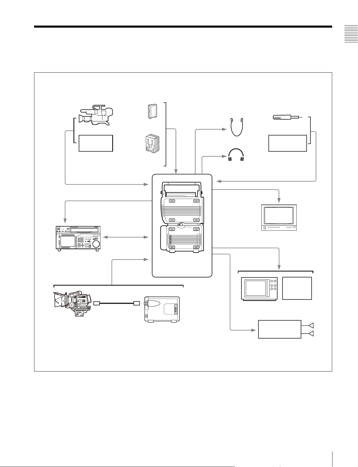
1-2 System Configuration
The following figure shows a system configured around
the SRW-1 and SRPC-1.
HD color video camera
BATTERY/
Switching
BP-GL95
DC IN
Chapter 1 Overview
Microphone
HD VTR etc.
HD SDI video/
audio input
HD SDI video/
audio output
HD DIGITAL VIDEO CASSETTE RECORDER
SRW-5000/5500
SRW-5000
9-pin remote
control cable
REMOTE IN
FC2-PD50/PD250
Optical-Fiber Cable
AC-DN10/DN2B
SRW-1 + SRPC-1
+ HKSR-102
+ HKSR-103
Earphones
Headphones
HD video output (HD SDI)
SD video output (SDI)
SD video monitor
Audio input
Analog: 4 channels
AES/EBU: 4 channels
HD video monitor
VTR etc.
VTR,
FPU etc.
F23/F35 Digital Cinematography
Camera (with CA-F101 Optical
Fiber Camera Adapter)
HKSR-101 Optical Interface Unit
Audio output
Analog: 2 channels
AES/EBU: 12 channels
Stereo amplifier
1-2 System Configuration
Speakers
9
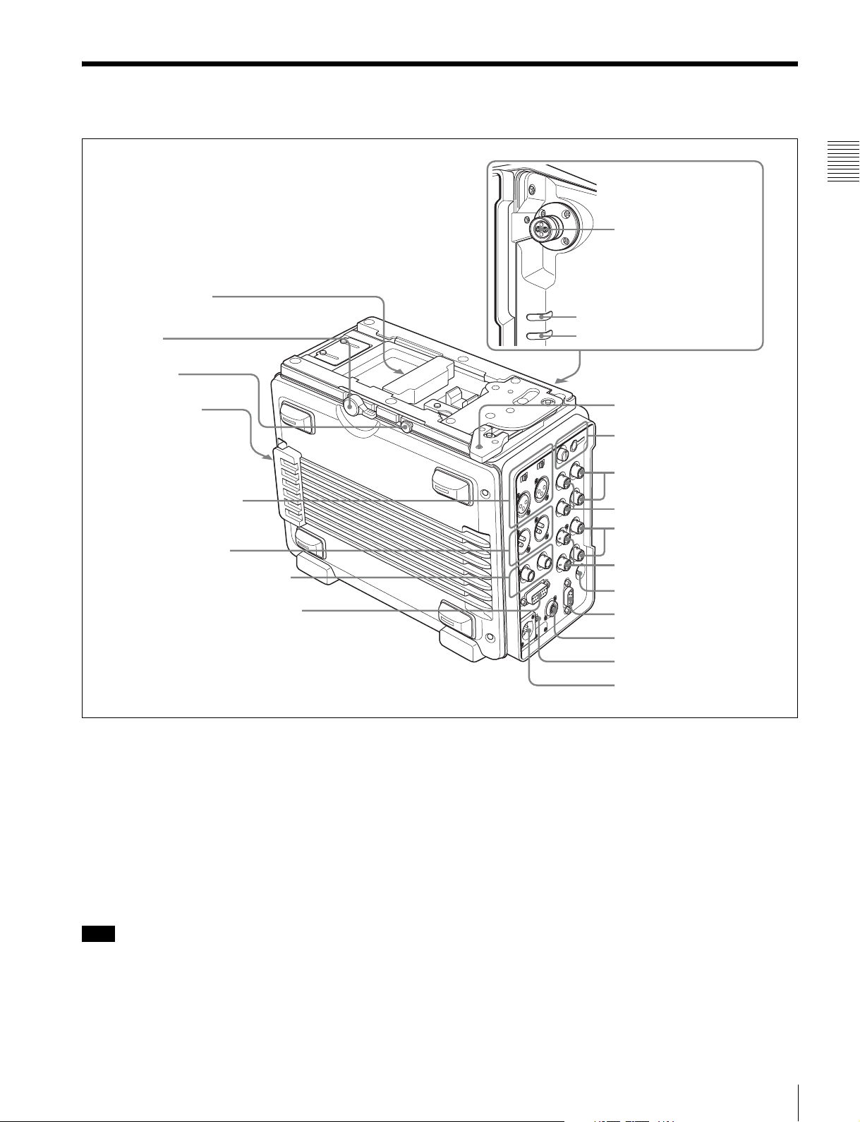
Names and Functions of
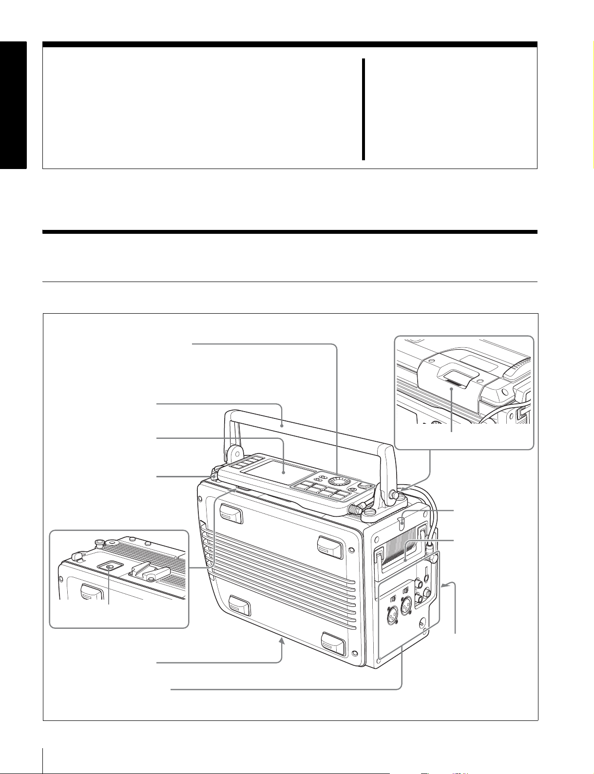
2-1 SRW-1
2-1-1 Principal Sections
Control panel (see page 11)
See 3-1-2 “Using the Control Panel
Extension Cable” (page 24) for more
information about using the control
panel apart from the recorder.
8 Top handle
Parts
Chapter
2
Display (see page 15)
7 Lock release button
(for control panel)
6 EJECT button
5 Processor connector
Connector panel (see page 17)
1 Cassette insertion slot
2 Tally indicator
3 Side handle
4 POWER (power
supply) indicator
10
2-1 SRW-1
a Cassette insertion slot
Insert cassettes.
into power save mode by the setting of SAVE MODE in
the SYSTEM Setup menu to “SAVE”.
For details, see 3-7-2 “Inserting and Ejecting Cassettes”
(page 38).
b Tally indicator
Lights during recording.
Flashes when errors have occurred (see “About Error
Messages” (page 104)) or when warnings have occurred
(see “About Warning Messages” (page 106)).
For more information about the tally indicator operation,
see “Warning System” (page 109).
c Side handle
When the top handle is removed, use this handle to join
and separate the SRW-1 and SRPC-1, for example.
d POWER (power supply) indicator
If the SRW-1 is docked to the SRPC-1 or the F23/F35,
lights in green when both the SRW-1 and the SRPC-1 or
F23/F35 are powered on. Flashes when the SRW-1 is put
2-1-2 Control Panel
For more information about SAVE MODE, see page 60.
e Processor connector
Connect the SRPC-1 or F23/F35.
Chapter 2 Names and Functions of Parts
f EJECT button
Pressing this button opens the lid of the cassette insertion
slot, allowing you to take out the inserted cassette.
g Lock release button (for control panel)
When removing the control panel, use this button.
For more information about using this button, see 3-1-2
“Using the Control Panel Extension Cable” (page 24).
h Top handle
Use to carry the SRW-1 or joined SRW-1/SRPC-1.
If you need to remove the top handle from the SRW-1
body, use a coin driver, etc. to loosen the four screws.
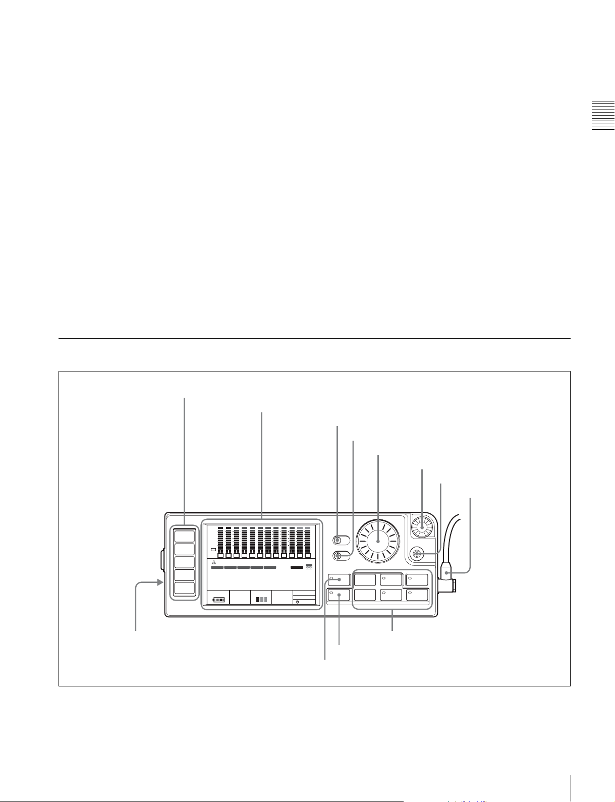
1 Menu selection buttons
HOME
TC
VIDEO
AUDIO
SYSTEM
qs Memory Stick slot
2 Display
ANLG
ANLG
SDI
SDI
SDI
SDI
SDI
SDI
SDI
EMP
EMP
EMP
L R
L R
L R
7
8
9
IN: --:--:--:--
1080
S59P
(29PsF)
4:2:2
L R
10
SRW-1
SDI
EMP
dB
0
-10
-20
-30
-60
EMP
EMP
EMP
EMP
EMP
PB
L R
L R
1
2
OOOO
TCR
LTC
EMP
L R
L R
L R
L R
3
4
5
6
PLAY LOCK
INTRPDFEXT-LK KEY
00H00M00S00
12.2V REMAIN CH.COND
18min
A/E
A/E
OFF ON
EMP
EMP
L R
L R
11
12
OFF ON
INHI
RECINHI
F
LOCAL
PB
21:46
qa EJECT button
3 KEY INHI switch
4 LIGHT switch
5 ADJUST knob
KEY INHI
LIGHT
ADJUST
EJECT STOP PLAY
xZzB
REW F FWD PAUSE
FUNC
mXM
9 Tape transport control buttons
0 FUNC button
6 SELECT/ENTER dial
7 BACK button
8 Control panel
connection cable
SELECT/ENTER
BACK
REC
a Menu selection buttons
Select the menu shown on the display.
HOME button: Displays the HOME screen. The HOME
screen displays audio levels, operating status,
warnings, time data, and other information.
2-1 SRW-1
11

TC button: Displays the TC (timecode) Setup menu (see
page 46). This menu allows you to switch between
LTC and VITC, to switch between DF and NDF, and
to display timecode on an external monitor.
VIDEO button: Displays the VIDEO Setup menu (see
page 50). This menu allows you to make settings
related to video.
AUDIO button: Displays the AUDIO Setup menu (see
Chapter 2 Names and Functions of Parts
page 52). This menu allows you to make settings
related to audio.
SYSTEM button: Displays the SYSTEM Setup menu
(see page 54). This menu allows you to make settings
related to the entire systems, such as recording format,
power, and test signal output.
See Chapter 4 “Menu Settings” (page 44) for more
information about menus.
ON: All operation buttons are disabled.
OFF: During recording, only the STOP button and
PAUSE button are enabled. All buttons are enabled
when the system is not recording.
When the KEY INHI item in the SYSTEM Setup menu is
set to MAP, the operation buttons follow the settings of the
LOCAL KEYMAP item.
d LIGHT switch
The backlight comes on when this is set to ON.
e ADJUST knob
Use to adjust audio levels, etc.
f SELECT/ENTER dial
When a menu is displayed, you can rotate this dial to move
the cursor, and press it to change and confirm settings.
b Display
Displays menus, audio levels, warning, operating status,
time data, remaining tape time, and remaining battery
g BACK button
When a menu is displayed, you can press this button to
back up one level in the menu structure.
power.
h Control panel connection cable
For details, see 2-1-3 “Display” (page 15).
c KEY INHI (inhibit) switch
When the KEY INHI item (see page 57) in the SYSTEM
Setup menu is set to ALL, setting this switch to ON
disables operation buttons, to prevent misoperations due to
Connect to the SRW-1 CTRL PANEL connector.
i Tape transport control buttons
Use these buttons for tape transport operations.
The functions of the buttons change when they are pressed
together with the FUNC button.
accidental button operations.
Name Pressed alone Pressed with FUNC button
STOP button Stops tape transport.
Pressing this button while in standby on
mode resets the still timer (see page
58).
Pressing the button while in standby off
mode puts the SRW-1 into standby on
mode.
Puts the SRW-1 into standby off mode.
12
2-1 SRW-1
Name Pressed alone Pressed with FUNC button
PLAY button and
indicator
Starts playback. (The indicator lights
during playback.)
To start recording, press this button
with the REC button held down.
Pressed with tape transport stopped: Searches for the
recording end point and then stops.
When SYSTEM >SERVO >EOS MODE is set to
“NORM” (factory default setting), rewinds for about five
seconds and then plays for about 10 seconds. If the
recording end point is located in that section, playback
stops at that point and the unit enters recording pause
mode. If the recording end point is not located in that
section, playback continues for about 10 seconds and
then stops.
When SYSTEM >SERVO >EOS MODE is set to
“LONG”, the 10-second search time limit described
above does not apply. Once playback starts, the search
continues until the recording end point is found.
Pressed with recording paused: Plays back the most
recently recorded material, and then returns to recording
pause mode (recording review). When SYSTEM
>SERVO >REC REVIEW is set to “NORM” (factory
default setting), one press of this button rewinds the tape
about 3 seconds and then starts playback. You can keep
the PLAY button pressed together with the FUNC button
to rewind the tape as long as the buttons are held down
(up to a maximum of 10 seconds), and then start
playback. Recording review allows you to check whether
the material was recorded correctly.
When SYSTEM >SERVO >REC REVIEW is set to “ALL”,
one press of this button rewinds up to the beginning of
the cut recorded last and then starts playback.
Note
REC review is not available unless at least 3 seconds have
been recorded.
REC button and
indicator
Pressing PLAY button with this button
held down starts recording. (The
indicator lights during recording.)
Pressing the button with recording
paused in standby off mode puts the
SRW-1 into standby on mode.
If you press this button during stop, fast
forward, or rewind or when no cassette
Temporarily memorizes the time data of the current position
(Mark In).
Mark IN data is displayed in the format “IN: xx:xx:xx:xx” in
the time data field of the display, and can be used for cueup.
Note
The Mark IN data is memorized in the unit’s internal memory
only. It is erased when you eject the cassette.
is inserted, the SRW-1 enters E-E
a)
mode
E-E signals
. In this mode you can monitor
b)
output from the HD SDI
OUT A/B connectors or the MONITOR
OUT HD SDI/SD SDI connectors of the
SRPC-1. While an E-E signal is being
monitored, the monitor output format
(see page 37) is displayed for a few
seconds.
REW (rewind) button
and indicator
Rewinds the tape. (The indicator lights
during rewinding, and goes out when
rewinding completes.)
When the REW button is pressed again
during rewinding, the operation
changes to the search mode same as
the button is pressed together with the
FUNC button (searching at the same
speed as searching was stopped
previously).
Executes reverse direction searches. With each press, the
search speed changes in the order × 2 t × 5 t × 8 t ×
2 normal speed.... If a search is interrupted by another
operation, the next search is performed at the speed in effect
at the time of the interruption.
Note
When using the SRW-1 with 880 Mbps recording rate, × 8
normal speed search is disabled.
For information about recording rate, see FORMAT
>SIGNAL in the SYSTEM Setup menu on page 55.
Chapter 2 Names and Functions of Parts
2-1 SRW-1
13
Name Pressed alone Pressed with FUNC button
F FWD (fast forward)
button and indicator
Chapter 2 Names and Functions of Parts
PAUSE button and
indicator
a) E-E mode:
A state in which E-E signals can be monitored. Commonly used to monitor
input signals before they are recorded.
b) E-E (electric to electric) signal:
A signal which passes solely through internal circuitry, and not through
pathways in which magnetic conversion takes place, such as magnetic
heads and tapes.
Fast forwards the tape. (The indicator
lights during fast forwarding, and goes
out when fast forwarding completes.)
When the F FWD button is pressed
again during fast forwarding, the
operation changes to the search mode
same as the button is pressed together
with the FUNC button (searching at the
same speed as searching was stopped
previously).
Pauses tape transport. (The indicator
flashes during pause.)
To resume tape transport, press the
button again.
Executes forward direction searches. With each press, the
search speed changes in the order × 2 t × 5 t × 8 t ×
2 normal speed.... If a search is interrupted by another
operation, the next search is performed at the speed in effect
at the time of the interruption.
Note
When using the SRW-1 with 880 Mbps recording rate, × 8
normal speed search is disabled.
For information about recording rate, see FORMAT
>SIGNAL in the SYSTEM Setup menu on page 55.
Cue up a time data position specified with FUNC+REC
button or SYSTEM >EDIT >IN POINT and stops. The
specified time data (Mark IN data) is displayed in the format
“IN: xx:xx:xx:xx” in the time data field of the display.
Note
The Mark IN data is memorized in the unit’s internal memory
only. It is erased when you eject the cassette.
j FUNC (function) button
When the tape transport control buttons are pressed with
this button held down, the functions of the buttons change.
For details, see “9 Tape transport control buttons” (see
page 12).
When the HOME button is pressed with this button held
down, switches the display at the bottom of the HOME
screen.
For details, see 2-1-3 “Display” (page 15).
k EJECT button and indicator
Pressing the button opens the cover of the cassette
insertion slot so that you can remove a cassette. The
indicator lights during removal.
l Memory Stick slot
Allows you to insert a “Memory Stick”.
For details, see 3-8 ““Memory Stick” Handling” (page
40).
14
2-1 SRW-1
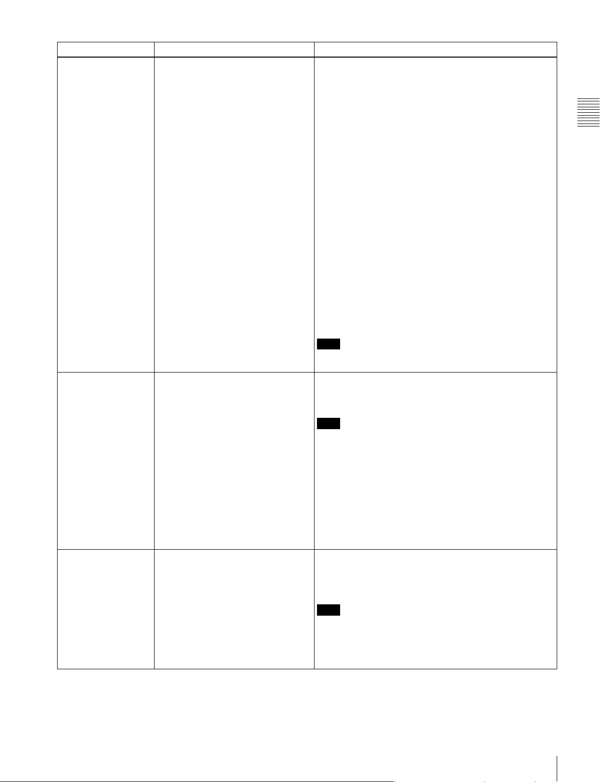
2-1-3 Display
00H00M00S00
00H26M02S12
This manual refers to the screen shown below as the
HOME screen.
1 Audio level meters
ANA
ANA
SDI
SDI
SDI
SDI
SDI
SDI
SDI
SDI
dB
0
-10
-20
-30
-60
EMP
EMP
EMP
EMP
EMP
EMP
EMP
PB
L R
L R
L R
L R
1
2
OOOO
TCR
LTC
00H 00M 00S 00F
LTC VITC AU
12.2V
L R
3
4
5
PLAY LOCK
INTRP
DF
REMAIN CH.COND
18min
L R
6
L R
7
EXT-LK
EMP
L R
8
IN: --:--:--:--INDLY:
C
1080
S59P
(29PsF)
4:2:2
A/E
EMP
EMP
EMP
L R
L R
L R
9
10
11
*SRW-1
KEY
INHI
LOCAL
PB SAVE
21:46
5 Signal format
6 Channel condition/RF indicator
7 Remaining tape time
8 Battery level/external power supply voltage
A/E
EMP
L R
12
RECINHI
4 Status
2 Operation status and warnings
When you press the HOME button with the FUNC
button held down, the sections 4 to 7 are replaced
by the displays shown below by 9 and 0.
SYS : 1080 23.98PsF 4:4:4 SQ
PB : 1080 23.98PsF 4:4:4 SQ
MON : 1080 23.98PsF/525 59.94I
3 Time data
SYS : 1080 S59P(23PsF) 4:2:2
FPS : 8 / 8 FRM(MODE:VTR)
MEM : 21 %
Chapter 2 Names and Functions of Parts
F
C
45min
12.8V
9 Signal formats
F
C
50min
12.8V
a Audio level meters
Display recording audio levels in recording and E-E mode.
Display playback audio levels during playback.
The indications in the top row show the audio input signal
type. The numbers 1 to 12 at the bottom are the numbers of
audio tracks on the tape.
b Operation status and warnings
Display the operation status of the system and warnings.
The principal information items are as follows.
TCR/TCG/UBR/UBG/CTL: Type of time data being
displayed.
LTC/VITC: When timecode is being displayed, whether
it is LTC or VITC.
1)
INTRP: Indicates that timecode could not be read
accurately, and has been interpolated.
DF/NDF: Whether the system is in DF (drop-frame) or
NDF (non-drop frame) mode.
EXT-LK: Timecode is locked to external timecode.
KEY INHI: The KEY INHI switch is set to ON.
REC INHI: The cassette is record inhibited.
SRW-1: The model name is displayed as follows,
depending on the operating status of the unit.
0 SR Motion
One asterisk (*) before model name: The unit is in
Power Save Mode 1.
Two asterisks (**) before model name: The unit is in
Power Save Mode 2.
SRW-1:CAM: The unit is docked on the F23/F35.
SRW-1=CAM: The unit is connected by optical fiber
to the HDC-F950.
1) VITC (Vertical Interval Time Code):
Timecode that is inserted on two lines in the vertical blanking interval.
This type of timecode can be read even during very slow playback.
For more information about warnings, see “About
Warning Messages” (page 106).
c Time data
Displays time data for the current tape position. The type
of time data is CTL
1)
(tape running time), timecode, or
user bits, as selected with TIMER SEL in the TC Setup
menu (see page 46).
When Mark In data has been set by the FUNC + REC
buttons or SYSTEM >EDIT >IN POINT, it is displayed in
the format “IN: xx:xx:xx:xx” beneath the time data for the
2-1 SRW-1
15

current tape position (right side). When no Mark In data
has been set, “IN: --:--:--:--” appears.
When one or more of the menu items
TC >OTHERS(MAIN) >LTC Delay,
TC >OTHERS(MAIN) >VITC Delay and
AUDIO>INPUT DELAY are set to something other than
“NO Delay”, “IN DLY:” appears under (left side) the time
data of the current position and the LTC, VITC, and AU
Chapter 2 Names and Functions of Parts
indicators light according to those item settings of
something other than “NO Delay”.
Green bar: Recording signal quality is good.
Red bar: Recording signal quality is degraded. If this
continues, head cleaning or internal inspection is
needed.
g Remaining tape time
Displays the time remaining on the tape. “TOP” is
displayed at the start of the tape, and “END” is displayed
at the end. The time display flashes when the tape is within
three minutes of the end.
1) CTL signal:
This is a control signal consisting of a pulse signal recorded longitudinally
on the tape for every frame of video.
d Status
Displays the following status information.
Upper row: Displays the setting of REMOTE/LOCAL in
the SYSTEM Setup menu (see page 57). If REMOTE
appears, the unit can be controlled from the device
connected to the REMOTE IN connector (see page
20).
Middle row: Displays the setting of POWER >MODE
(PB or EE) in the SYSTEM Setup menu (see page 60).
When POWER >SAVE MODE is set to “SAVE”,
“SAVE” appears on the right side of the MODE
setting display.
Lower row: Displays the real time.
e Signal format
Displays the format of recording signals.
When the unit is in one of the following modes, an
alphabetic character indicating the mode appears before
the number of lines.
T: Auto Timer Rec
M: Manual Timer Rec
C: Cache Rec
When SR Motion is used, “S” appears before the system
frequency.
f Channel condition/RF indicator
During playback, the letters “CH.COND” appear and one
of the three bars (green, yellow, and red) lights to indicate
the playback signal condition.
Green bar: Playback signal quality is good.
Yellow bar: Playback signal quality is degraded, but
playback is possible.
Red bar: Playback signal quality is degraded. If this
continues, head cleaning or internal inspection is
needed.
During playback with manual tracking control, the
“CH.COND” indication in the HOME screen flashes in
yellow (see page 73). “CH.COND” flashes during auto
tracking operation.
During recording, the letters “RF” appear and a green bar
or a red bar lights to indicate the recording signal
condition. Normally the green bar lights. If a recording
problem occurs, the red bar lights.
h Battery level/external power supply voltage
Displays the current power level of the battery pack. When
the battery pack is fully charged, all seven segments light
up. As the battery pack discharges, the segments go out
from left to right. When the battery pack is almost
exhausted, the voltage indication and the tally indicator
flash, and a warning tone sounds intermittently. When the
battery pack is completely exhausted, the tally indicator
flashes at a higher rate and the warning tone sounds
continuously.
For more information, see “Warning System” (page 109).
When an external power supply is connected, the voltage
of the external power supply is shown. However, the input
voltage to the DC IN connector is not shown in itself.
Rather the voltage actually used by the system is shown
(lower than the input voltage).
For more information about the relation between segments
and battery voltage, see 3-4-4 “Checking the Power and
Voltage” (page 35).
i Signal formats
When you press the HOME button with the FUNC button
held down, displays the system, playback, and monitor
output signal formats, in that order from the top row.
When the unit is in one of the following modes, an
alphabetic character indicating the mode appears before
the number of lines.
T: Auto Timer Rec
M: Manual Timer Rec
C: Cache Rec
When SR Motion is used, “S” appears before the system
frequency.
When you play a tape that was recorded with SR Motion,
the FPS value in SR Motion recording is shown in the
playback frequency position (see page 81).
During LUT conversion for monitor output, “(LUT)”
appears after the monitor output display (see page 121).
See Chapter 7 “SR Motion (With HKSR-102 Installed)”
(page 78) for more information about the SR Motion
function.
16
2-1 SRW-1
j SR Motion
When the SYSTEM >FORMAT >SELECT FPS menu
item is set to “ON” or “VTR” and the signal format is
being displayed, pressing both the FUNC and HOME
buttons together displays the FPS or FRM on the second
line and the memory level on the third line.
See Chapter 7 “SR Motion (With HKSR-102 Installed)”
(page 78) for more information about the SR Motion
function.
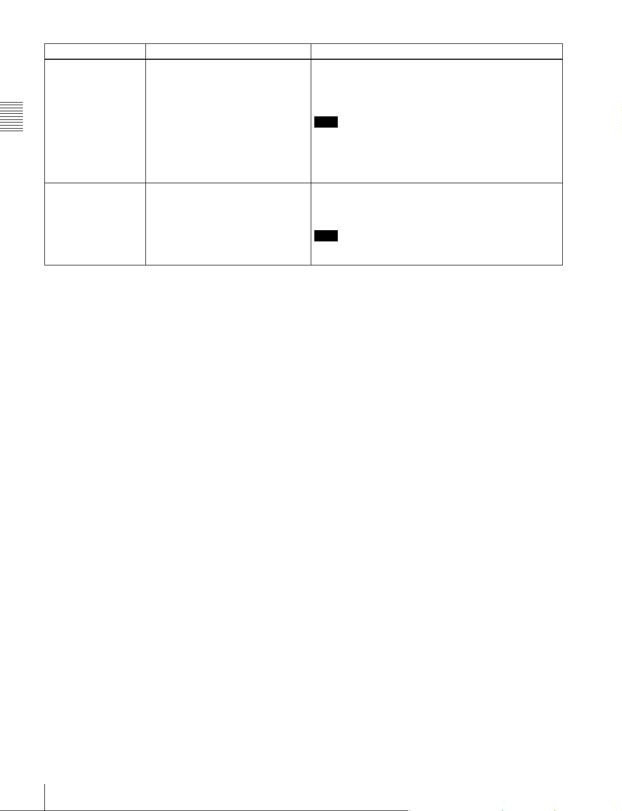
2-1-4 Connector Panel
Chapter 2 Names and Functions of Parts
1 TC IN connector
2 CTRL PANEL connector
3 EARPHONES jack and
LEVEL knob
6 AUDIO INPUT CH-1 and CH-2 connectors and input selection switches
a TC IN (timecode input) connector (BNC type)
Connect to the timecode output connector of an external
device such as a timecode generator or VTR. Use this
connector when locking the internal timecode generator to
external timecode.
b CTRL (control) PANEL connector
Connect the control panel. You can remove the short cable
connected when the SRW-1 is shipped from the factory
and replace it with the supplied extension cable.
For details, see 3-1-2 “Using the Control Panel Extension
Cable” (page 24).
4 TC OUT connector
5 POWER ON/OFF switch
c EARPHONES jack (stereo minijack) and LEVEL
knob
Use this connector to attach earphones or stereo
headphones equipped with a stereo miniplug, for use in
monitoring audio during recording and playback. Adjust
the audio level with the LEVEL knob.
A warning tone is output to the earphones/headphones
when a warning is lit on the control panel display.
d TC OUT (timecode output) connector (BNC type)
Connect to the timecode input connector of an external
device such as a timecode reader or VTR.
2-1 SRW-1
17

The timecode output is determined by the setting of
OTHERS (MAIN) >TC OUT in the TC Setup menu as
follows.
TCG (timecode generator): Timecode generated by the
timecode generator is output, delayed by 1 frame.
(This maintains synchronization with the output
video).
AUTO: During recording (including E-E mode), timecode
Chapter 2 Names and Functions of Parts
generated by the timecode generator is output, delayed
by 1 frame. (This maintains synchronization with the
output video).
During playback, the LTC signal read from the tape is
output.
THRU: Timecode input to the TC IN connector is through
output.
TCG (No Delay): Timecode generated by the timecode
generator is output, with no delay. (The timecode is
out of synchronization with the output video, being 1
frame in advance of the video.) Select this setting
when you want to synchronize other devices, using the
timecode generator of this unit as the master.
e POWER ON/OFF switch
When the SRPC-1 power is on, push this switch up to the
ON side to power the SRW-1 on. To power the SRW-1 off,
push the switch down to the OFF side.
Normally leave this switch on the ON side since the SRW1 is powered on and off automatically by the SRPC-1
POWER ON/OFF switch.
f AUDIO INPUT CH-1 and CH-2 (analog audio
input channels 1 and 2) connectors (XLR 3-pin,
female) and input selection switches
These connectors allow up to four channels of analog
audio signals to be input from microphones and other
external audio devices.
Set the input selection switches as follows, depending on
the type and level of the input audio.
LINE: For line input
MIC: For microphone input
+48V ON: For input from microphones with external
power supply
18
2-1 SRW-1
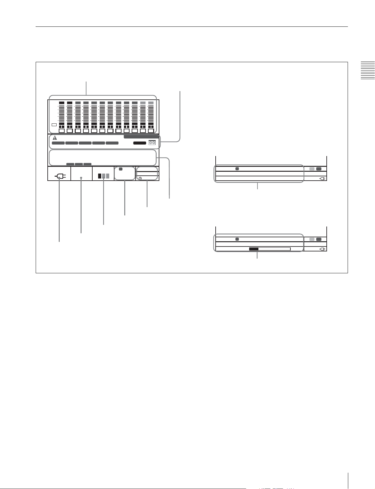
2-2 SRPC-1
1 Recorder connector
2 Lock lever
3 Release knob
Chapter 2 Names and Functions of Parts
w; CAMERA connector
(When optional HKSR101 installed)
wa POWER indicator
ws Info indicator
4 Battery attachment
section
5 AUDIO INPUT CH-3 and
CH-4 connectors and input
selection switches
6 MONITOR OUT L and R
connectors
7 AES/EBU INPUT CH7/8 and CH9/10
connectors
8 AES/EBU OUTPUT CH1-12 connector
a Recorder connector
Connect the SRW-1 HD Portable Digital Recorder.
b Lock lever
After joining the SRW-1 and SRPC-1, rotate this lever to
lock the joint.
9 Assist lever
0 EARPHONES jack and
LEVEL knob
qa HD SDI OUT A and B
connectors
qs HD SDI IN A and B connectors
qd MONITOR OUT HD SDI
and SD SDI connectors
qf REF IN HD and SD connectors
qg POWER ON/OFF switch
qh REMOTE IN connector
qj CAMERA REMOTE IN
connector
qk EXT DC SELECT switch
ql DC IN connector
d Battery attachment section
Attach a BP-GL95 Battery Pack or AC-DN10/DN2B AC
Adaptor.
For details, see 3-4 “Power Supply Preparations” (page
34).
c Release knob
When separating the joined SRW-1 and SRPC-1, rotate the
assist lever while pulling out this knob.
Note
Once you have joined the SRW-1 and SRPC-1, do not pull
out the release knob except when you want to detach the
SRW-1 from the SRPC-1 because doing so results in
separation of these units.
e AUDIO INPUT CH-3 and CH-4 (analog audio
input channels 3 and 4) connectors (XLR 3-pin,
female) and input selection switches
These connectors allow up to four channels of analog
audio signals to be input.
Set the input selection switches as follows, depending on
the type and level of the input audio.
LINE: For line input
MIC: For microphone input
+48V ON: For input from microphones with external
power supply
2-2 SRPC-1
19

f MONITOR OUT (audio monitor output) L and R
connectors (XLR 3-pin, male)
Output audio monitor signals.
g AES/EBU INPUT CH7/8 and CH9/10 (digital
audio input channels 7/8 and 9/10) connectors
(BNC type)
These connectors allow up to four channels of AES/EBU
Chapter 2 Names and Functions of Parts
format digital audio signals to be input.
Note
The AES/EBU signals must be locked to the video signal.
h AES/EBU OUTPUT CH1-12 (digital audio output
channels 1 to 12) connector (D-sub 15-pin)
Outputs up to 12 channels of AES/EBU format digital
audio signals.
This connector is specially designed for this system. For
details, refer to the Maintenance Manual Volume 1.
i Assist lever
Use this lever when joining or separating the SRW-1 and
SRPC-1.
For more information on output signals, see “Relation
between recording and playback signals and output
signals to video monitors” (page 63) in 5-1-1 “Selecting
the System Signal Format”.
VTR operating status and timecode can be superimposed
on the output (see the CHAR(MON) item in the TC Setup
menu (page 48)).
n REF IN (reference signal input) HD and SD
connectors (BNC type)
Input a reference video signal with the correct frame
frequency.
HD connector: As an HD reference video signal, input a
tri-level bipolar sync signal.
SD connector: As an SD reference video signal, input a
video signal with a chroma burst signal (VBS) or black
and white video signal (VS).
When carrying out recording, set REFERENCE >MODE
in the SYSTEM Setup menu to “Input” so that the system
is synchronized with the input video signal.
To record the input video signal in synchronization with an
HD reference video signal, input an HD reference video
signal of the same phase as the input video signal.
j EARPHONES jack (stereo minijack) and LEVEL
knob
Use this connector to attach earphones or stereo
headphones equipped with a stereo miniplug, for use in
monitoring audio during recording and playback. Adjust
the audio level with the LEVEL knob.
A warning tone is output to the earphones/headphones
when a warning is lit on the control panel display.
k HD SDI OUT A and B connectors (BNC type)
Output HD SDI video and audio signals.
When the signal format has 720 lines or 1080 lines/30 or
fewer frames, the signals are output from the “A”
connector.
l HD SDI IN A and B connectors (BNC type)
Input HD SDI video and audio signals.
When the signal format has 720 lines or 1080 lines/30 or
fewer frames, input the signals to the “A” connector.
m MONITOR OUT (video monitor output) HD SDI
and SD SDI connectors (BNC type)
Output SDI video and audio signals for monitoring.
HD SDI connector: Outputs HD SDI video and audio
signals for monitoring.
The PD(MON) item in the VIDEO Setup menu (see
page 50) allows you to select whether pull-down
conversion of this output is performed or not.
SD SDI connector: Outputs SD SDI video and audio
signals for monitoring.
Regardless of signal format settings, these connectors
always output signals in 4:2:2 format.
Note
If you are not using SR Motion, the field frequency of the
input reference video signal must correspond to the system
frame frequency set with FORMAT >FRAME in the
SYSTEM Setup menu.
If you are using SR Motion, refer to the table on page 82
and input the reference video signal indicated there.
o POWER ON/OFF switch
Powers the SRPC-1 on when pushed up to the ON side. To
power the SRPC-1 off, push the switch down to the OFF
side.
When the SRW-1 is joined to the SRPC-1, this switch
powers both the SRW-1 and SRPC-1 on and off.
p REMOTE IN (remote control input) connector (9-
pin, female)
To use this unit as a playback-side VTR to perform editing
in combination with another HD VTR (e.g. SRW-5500,
etc.) and an editor such as a BVE-700/9100, use a 9-pin
remote control cable (optional) to connect this unit to the
controlling device.
Note
To control this unit from the device connected to this
connector, set REMOTE/LOCAL in the SYSTEM Setup
menu (see page 57) to RMT.
20
2-2 SRPC-1

q CAMERA REMOTE IN (remote control input)
connector (8-pin)
When the optional HKSR-101 Optical Interface Unit is
installed, you can connect an RM-B750/B150 Remote
Control Unit to this connector.
r EXT DC SELECT (external power selection)
switch
Select the operating mode when an external power supply
is connected.
AUTO: Normally use the external power supply
connected to the DC IN connector, but when its
voltage declines, automatically switch to the power
supply attached to the battery attachment section.
EXT (external): Always use only the external power
supply connected to the DC IN connector.
s DC IN connector (XLR 4-pin, male)
When using the optional AC-DN2B/DN10 AC Adaptor to
connect to an AC power source, connect the DC power
cord of the adaptor to this connector.
Use only the DC power cord supplied with the AC adapter.
t CAMERA connector (optical-fiber connector)
(when HKSR-101 installed)
Connect the F23/F35 Digital Cinema Camera by FC2PD50/PD250 Optical-Fiber Cable (optional).
A single optical-fiber cable can send and receive audio and
control signals multiplexed into video signals.
Chapter 2 Names and Functions of Parts
Refer to the HKSR-101 Installation Manual for
information about installing the HKSR-101.
Notes
• Power cannot be supplied from this unit to a camera over
optical-fiber cable.
• Communications errors can occur if dust accumulates on
the surface of the connector of the optical-fiber cable.
Always clean the CAMERA connector before use.
Whenever the CAMERA connector is not in use, always
cover it with the cap supplied with the HKSR-101.
Refer to the HKSR-101 Installation Manual for
information about cleaning the optical-fiber connector.
u POWER (power supply) indicator
Lights in green when the SRPC-1 is powered on. Flashes
when the SRW-1 is put into power save mode by the
setting of SAVE MODE in the SYSTEM Setup menu to
“SAVE”.
For more information about SAVE MODE, see page 60.
v Info (information) indicator
Normally not used.
2-2 SRPC-1
21
Preparations
3-1 Assembly
3-1-1 Joining the SRW-1 and SRPC-1
When using the optional HKSR-101 Optical Interface
Unit, refer to the HKSR-101 Installation Manual.
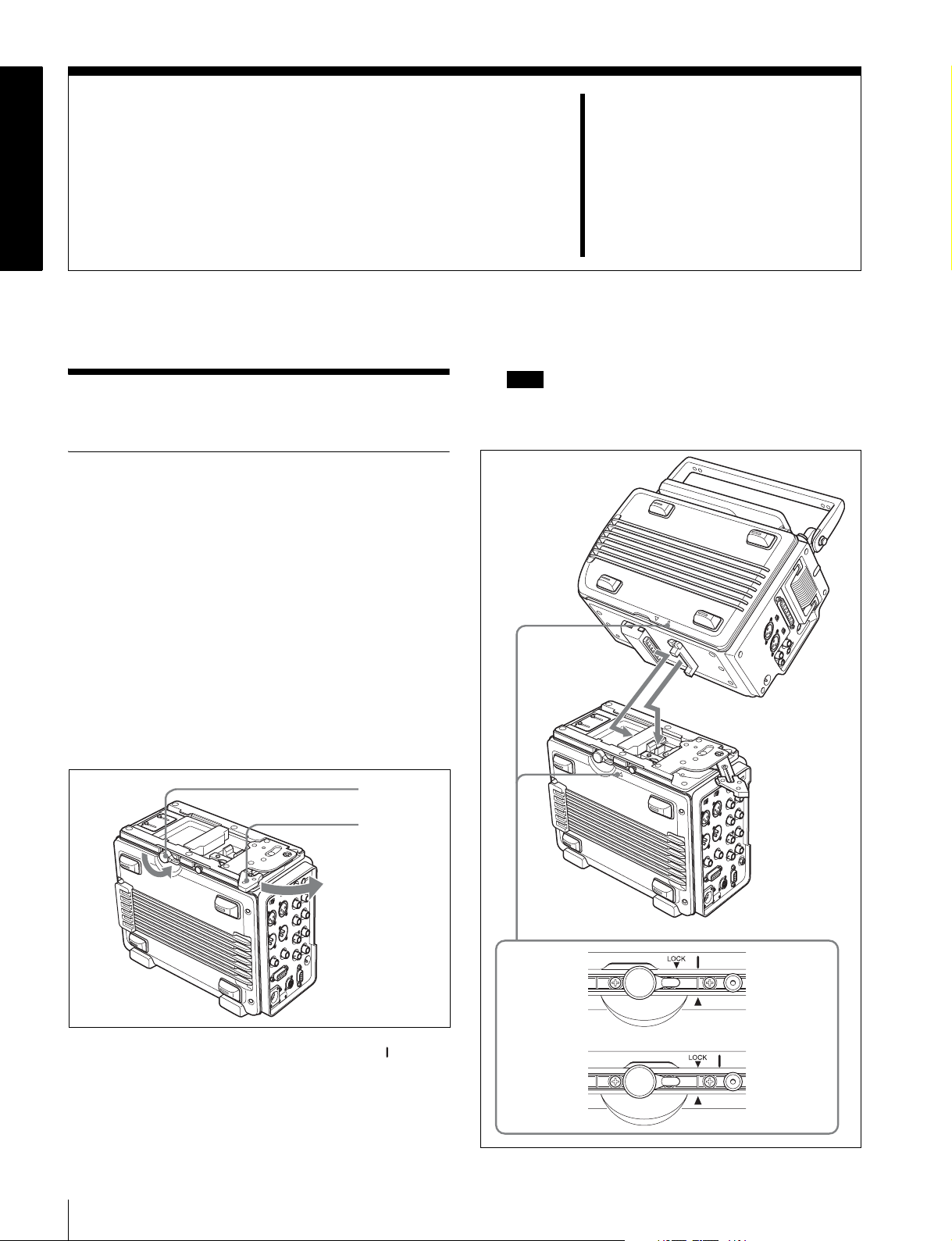
To mount the SRW-1 on the SRPC-1, proceed as follows.
1
Place the SRPC-1 on a flat, stable surface of a bench,
table or the like.
2
Rotate the lock lever counterclockwise (see the figure
for step 3) until it is almost horizontal.
Chapter
Note
If the top handle is detached from the SRW-1, grasp
the side handle with one hand and mount the SRW-1
while supporting it with your other hand.
3
3
Move the assist lever to the unlock position (rotate it in
the direction of the arrow as far as it will go).
Lock lever
Assist lever
4
Grasp the top handle of the SRW-1, align the mark on
the SRW-1 with the v mark on the SRPC-1 (see “To
release” in the following figure), and then place the
SRW-1 on the top of the SRPC-1.
To release
To lock
SRW-1 side
SRPC-1 side
SRW-1 side
SRPC-1 side
22
3-1 Assembly
5
Rotate the assist lever back to its original (lock)
position to align the LOCK V mark on the SRW-1
with the v mark on the SRPC-1. (See “To lock” in the
previous figure.)
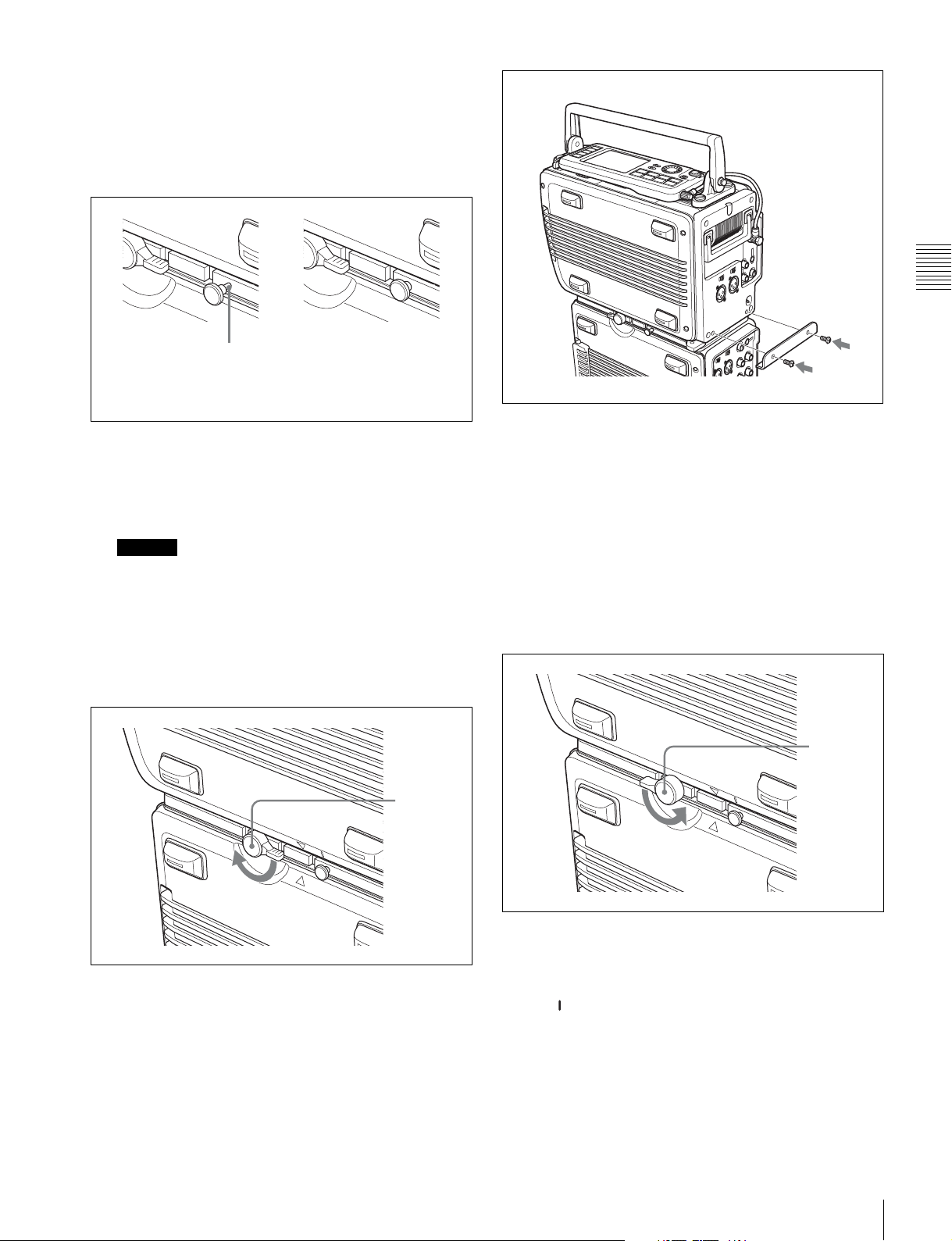
When you do this, check to be sure that the release
knob (see the following figure) is all the way in.
This part is visible.
Release knob is
not all the way in.
Next, by attempting to rotate the assist lever again to
the lock position, check to be sure that now the assist
lever will not go beyond half the way and that the
SRW-1 keeps joined to the SRPC-1.
Caution
The SRW-1 and SRPC-1 are not properly joined
unless the release knob is all the way in. They may
come apart, or the SRW-1 may fall off.
6
Rotate the lock lever on the side panel of the SRPC-1
in the direction of the arrow to lock the joint between
the SRPC-1 and SRW-1.
Release knob is
all the way in.
Assist lever
holding bracket
Screws (× 2)
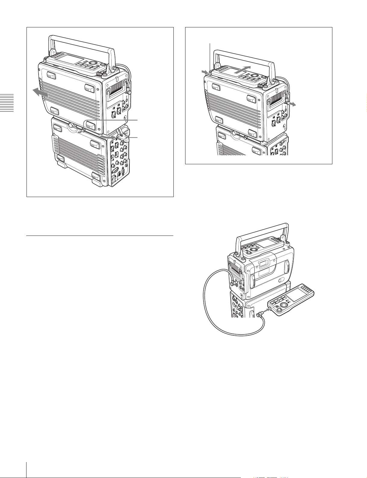
To detach the SRW-1 from the SRPC-1
1
Place the joined SRPC-1 and SRW-1 on a flat, stable
surface of a bench, table or the like.
2
Unscrew the assist lever holding bracket from the
body of the SRW-1.
3
Rotate the lock lever on the side panel of the SRPC-1
in the direction of the arrow to unlock the joint
between the SRPC-1 and SRW-1.
Lock lever
Chapter 3 Preparations
Lock lever
7
Remove the two screws from the holes on the SRW-1,
and use these two screws to mount the supplied assist
lever holding bracket on the SRW-1.
4
While pulling out the release knob on the side panel of
the SRPC-1, rotate the assist lever in the direction of
arrow and then slide the SRW-1.
The mark on the SRW-1 is aligned with the v mark
on the SRPC-1. (See “To release” in the figure on
page 22.)
3-1 Assembly
23
Lock release button (for control panel)
Remove cable
Chapter 3 Preparations
5
Lift the SRW-1 off the SRPC-1.
6
Move the assist lever to the lock position.
3-1-2 Using the Control Panel
Extension Cable
When they are shipped from the factory, the control panel
and SRW-1 are connected by a short cable. You can
replace this cable with the supplied extension cable, which
allows you to use the control panel apart from the SRW-1.
Proceed as follows.
Release knob
Assist lever
3
Remove the cable from the control panel and replace it
with the extension cable.
4
Connect the extension cable to the CTRL PANEL
connector on the SRW-1.
24
1
Disconnect the short cable from the CTRL PANEL
connector on the SRW-1. (See the following figure.)
2
While pressing the lock release button next to the
control panel, slide the control panel in the direction of
the arrow in the figure to separate the control panel
from the SRW-1 body.
3-1 Assembly
To secure the extension cable with the cable
clamp
You can attach the cable clamp supplied with the SRW-1
to secure part of the extension cable. Proceed as follows.
1
Remove the two screws from the SRW-1. (See
following figure.)
2
Attach the supplied cable clamp to the SRW-1 using
the screws removed in step 1.
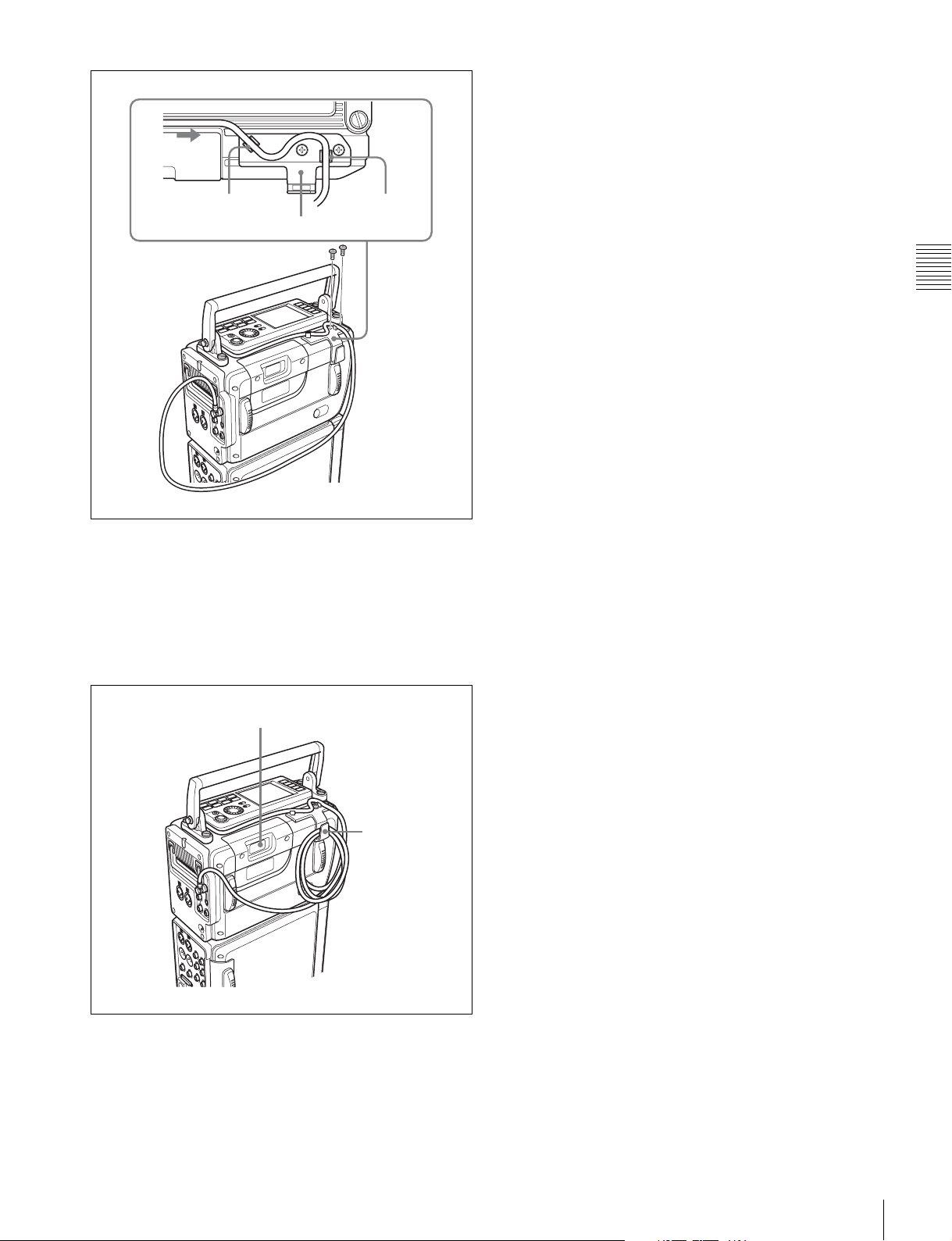
Groove A
Cable clamp
Screws
3
Gently pull the part of the cable closest to the control
Groove B
panel in the direction of the arrow so that there is
almost no slack, then fix the cable in groove A and
groove B. (See figure in step 2.)
4
While avoiding the cassette insertion slot, fix the slack
part of the rest of the cable in the clamp.
Chapter 3 Preparations
Cassette insertion slot
Clamp
3-1 Assembly
25
3-2 Connections
This section explains how to make connections for
recording and playback.
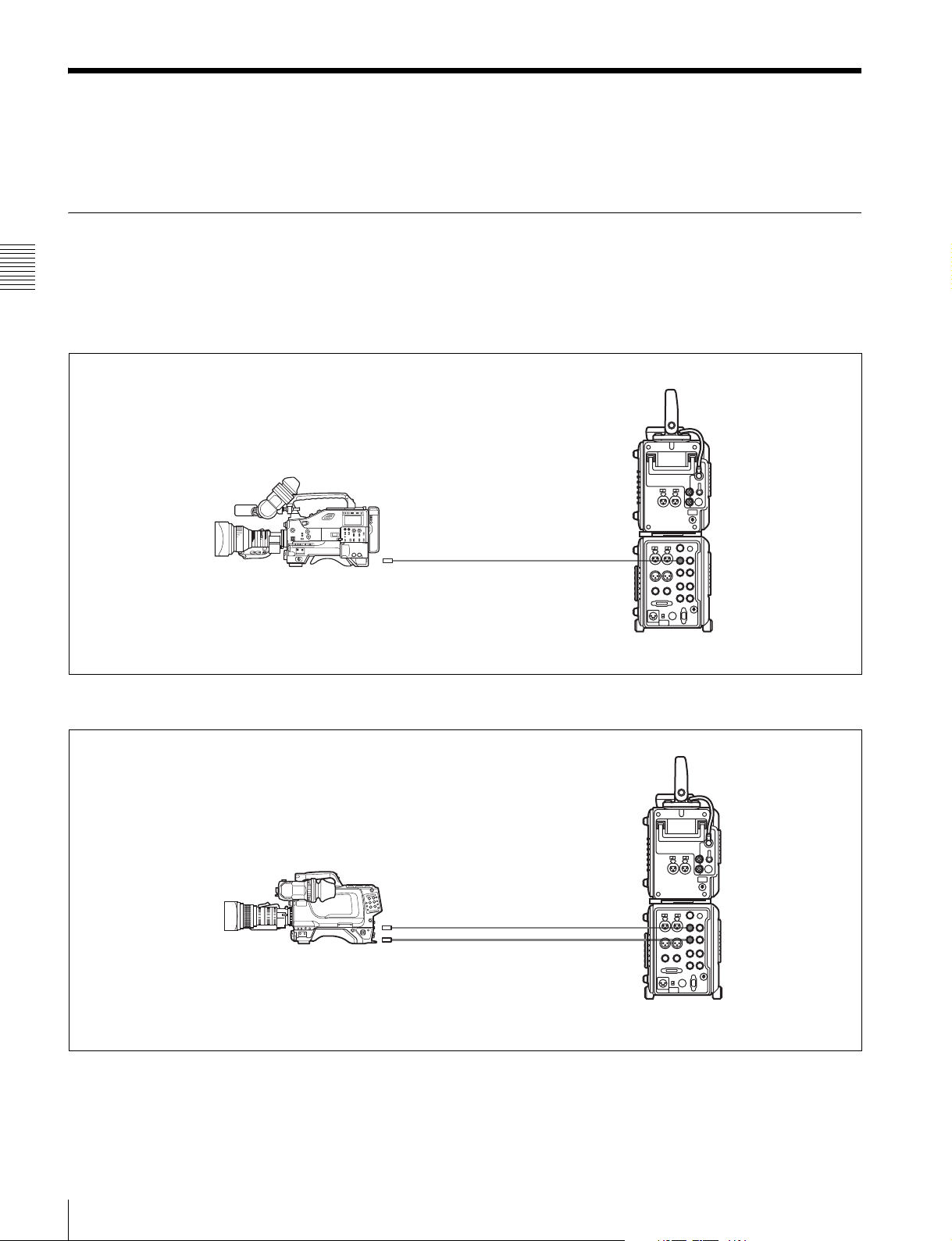
3-2-1 Connections for Recording
The following figures show connections between this unit
and a camera or camcorder.
Chapter 3 Preparations
About monitor connections, see the figures in 3-2-2
“Connections for Playback” (page 28).
To connect the HDW-F900R to record 4:2:2 signals
HD SDI OUT
HDW-F900R HD multi-format
camcorder
HD SDI IN A
To connect the HDC1500 to record RGB 4:4:4 or 4:2:2 50P/59P signals
SRW-1 + SRPC-1
26
3-2 Connections
HDC1500 multi-format
camera system
LINK A/B OUT HD SDI IN A
HD SDI IN B
SRW-1 + SRPC-1
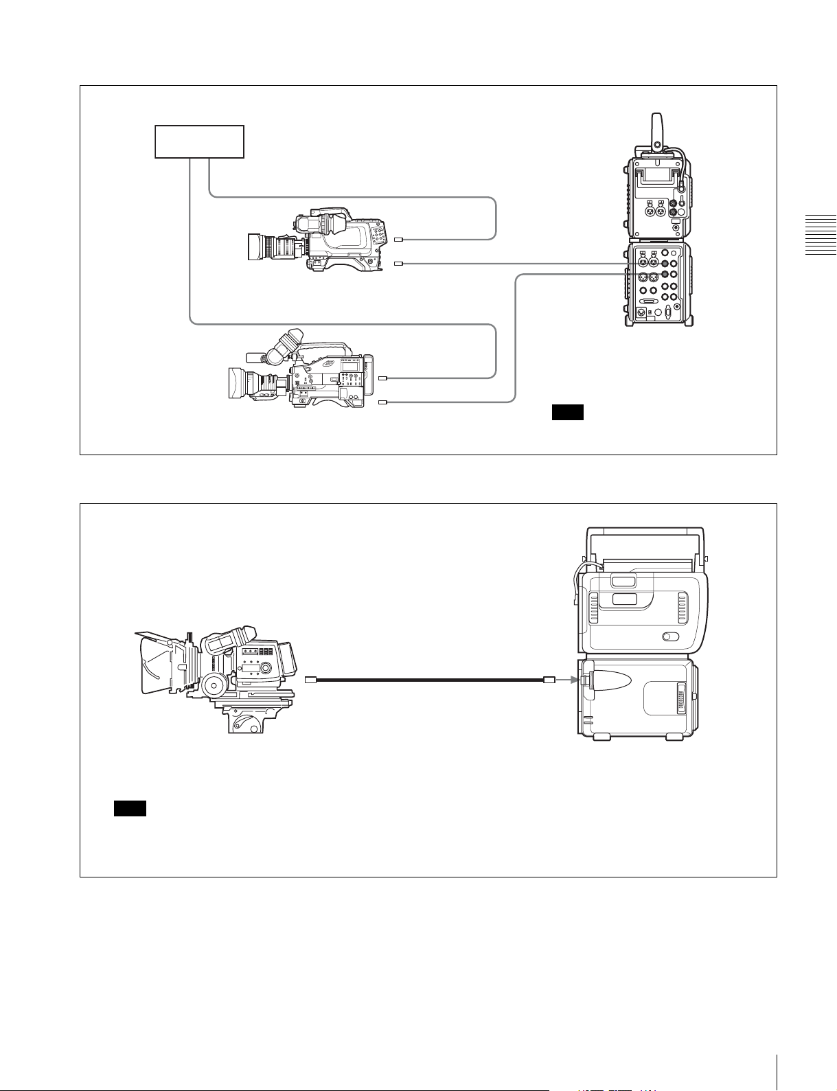
To record the output of 2 camera systems as 4:2:2 DUAL STREAM
Reference
signals
GENLOCK IN
LINK A OUT
HDC1500 multi-format
camera system
GENLOCK IN
HD SDI OUT
HDW-F900R HD multi-format
camcorder
To record 4:2:2 or 4:4:4 signals using optical-fiber cable
HD SDI IN A
HD SDI IN B
SRW-1 + SRPC-1
Note
Synchronize the two cameras.
Chapter 3 Preparations
CCU CAMERA
FC2-PD50/PD250 Optical-Fiber Cable (optional)
F23/F35 Digital Cinematography
Camera (with CA-F101 Optical
Fiber Camera Adapter)
Note
Set VIDEO I/O >VA INPUT in the VIDEO Setup menu to
CAM(Optical). Further, set CAM TYPE to F950 or STD,
depending on the type of camera system you are using.
SRW-1 + SRPC-1 + HKSR-101 (optional)
3-2 Connections
27
To record 4:2:2 or RGB 4:4:4 signals in
combination with the F23 or F35 (in
docked operation)
The available signal formats vary depending on the
camera with which this unit is combined.
“List of Camera Combinations and Available Functions”
(page 119).
SRW-1
Chapter 3 Preparations
For details, see
HKSR-102
(optional)
+ HKSR-103
(optional)
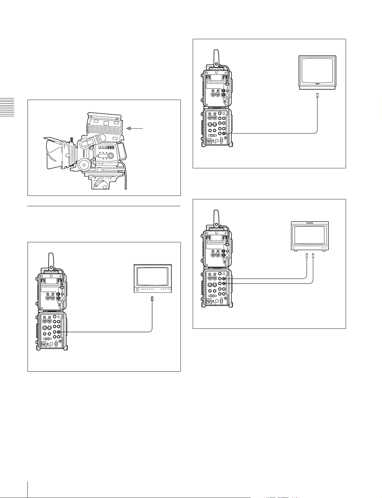
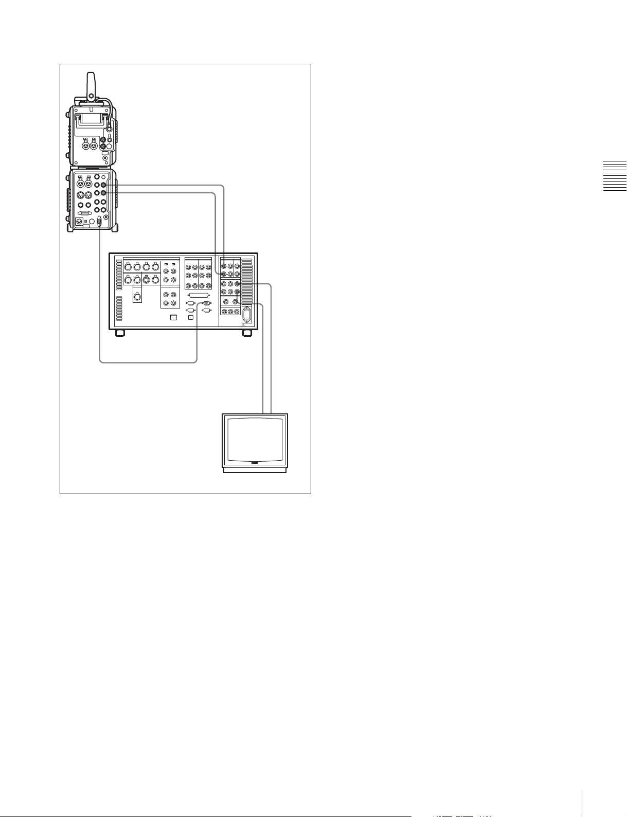
To connect an SD monitor
SD monitor
SD video input
SDI (D1)
MONITOR OUT SD SDI
SRW-1 + SRPC-1
F23/F35
3-2-2 Connections for Playback
To connect an HD monitor
HD monitor
HD video input
HD SDI
MONITOR OUT HD SDI
SRW-1 + SRPC-1
To connect an HD monitor supporting RGB
4:4:4 or 1080 50P/60P (Dual Link)
BVM-F24 HD monitor
LINK A IN LINK B IN
HD SDI OUT A
HD SDI OUT B
SRW-1 + SRPC-1
28
3-2 Connections
To use as player for editing
SRW-1 + SRPC-1
HD SDI OUT A
HD SDI OUT B
Chapter 3 Preparations
REMOTE
IN
SRW-5000/5500
REMOTE 1-I/O(9P)
a) Illustration: SRW-5000
HD SDI INPUT B
a)
HD SDI INPUT A
HD SDI
OUTPUT A
HD SDI
OUTPUT B
HD video
input
HD SDI
(LINK B IN)
HD monitor
HD SDI
(LINK A IN)
3-2 Connections
29
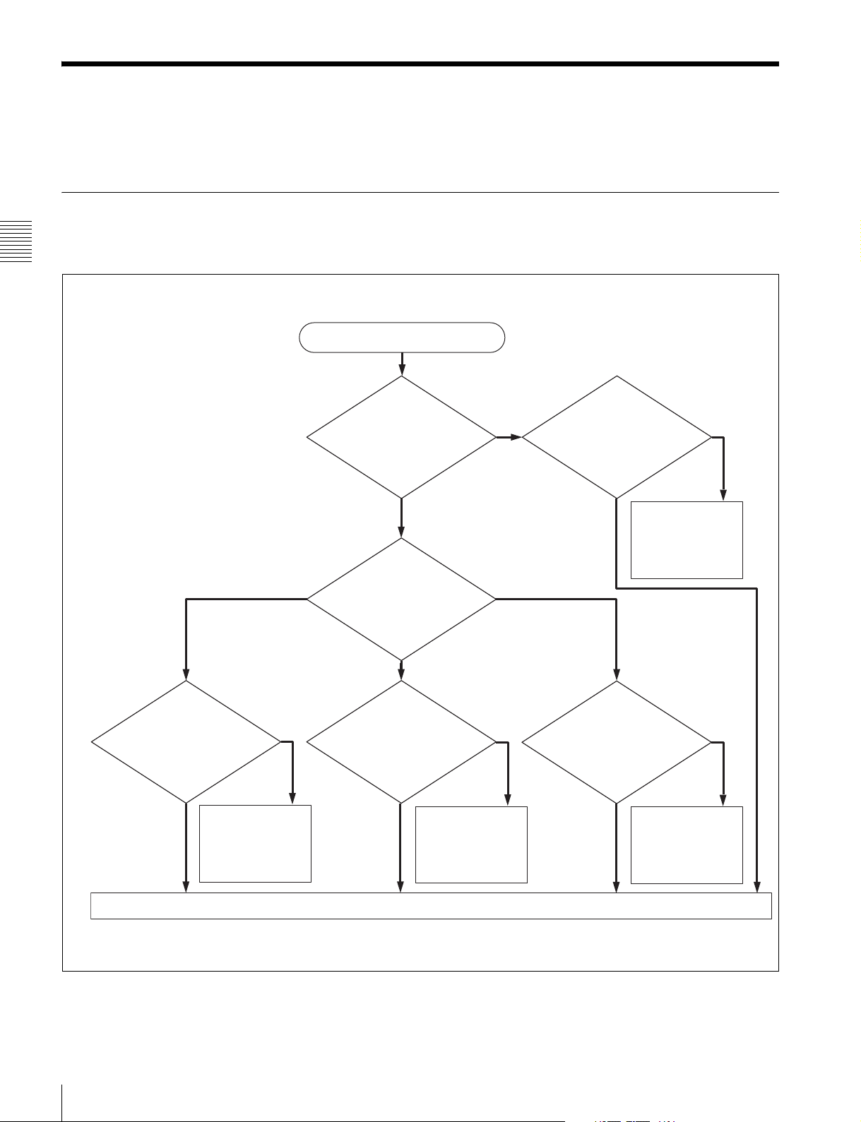
3-3 About Reference Sync Signals
This section explains how to select reference signals for
video output signals.
3-3-1 Reference Signals for Video Output Signals
The video signals output from this system are
synchronized as shown below, depending on the operating
Chapter 3 Preparations
state of the system, SYSTEM Setup menu settings (see
page 54), and input signals.
Start
SYSTEM Setup >
REFERENCE >
MODE setting?
External
SYSTEM Setup >
REFERENCE >
EXTERNAL setting?
Input
HD&SDSD
Signals input to HD SDI
IN A/B connectors?
No
Sync to signals
input to HD SDI IN
A/B connectors
Yes
Signals with correct
frequency input to REF
IN SD connector?
No
Sync to reference
video signals input
to REF IN SD
connector
Yes
HD
Signals with correct
frequency input to REF
IN HD connector?
No
Sync to reference
video signals input
to REF IN HD
connector
No external sync (internal sync)
Yes
Signals with correct
frequency input to
REF IN HD and SD
connectors?
No
Sync to reference
video signals input
to REF IN HD and
SD connectors
Yes
30
3-3 About Reference Sync Signals
 Loading...