

Page 1

HD A/V MULTIPLEXER BOARD
HKSP-105
! WARNING
This manual is intended for qualified service personnel only.
To reduce the risk of electric shock, fire or injury, do not perform any servicing other than that
contained in the operating instructions unless you are qualified to do so. Refer all servicing to
qualified service personnel.
! WARNUNG
Die Anleitung ist nur für qualifiziertes Fachpersonal bestimmt.
Alle Wartungsarbeiten dürfen nur von qualifiziertem Fachpersonal ausgeführt werden. Um die
Gefahr eines elektrischen Schlages, Feuergefahr und Verletzungen zu vermeiden, sind bei
Wartungsarbeiten strikt die Angaben in der Anleitung zu befolgen. Andere als die angegeben
Wartungsarbeiten dürfen nur von Personen ausgeführt werden, die eine spezielle Befähigung
dazu besitzen.
! AVERTISSEMENT
Ce manual est destiné uniquement aux personnes compétentes en charge de l’entretien. Afin
de réduire les risques de décharge électrique, d’incendie ou de blessure n’effectuer que les
réparations indiquées dans le mode d’emploi à moins d’être qualifié pour en effectuer d’autres.
Pour toute réparation faire appel à une personne compétente uniquement.
INSTALLATION MANUAL
2nd Edition
Serial No. 10273 and Higher
Page 2

Page 3

Purpose of this manual
This manual is an installation manual of HD A/V Multiplexer Board HKSP-105.
This manual is intended for use by trained system and
service engineers, and describes information regarding
installation.
Related manuals
Besides this installation manual, the following manuals are
available for the HKSP-105.
. Maintenance Manual (Available on request)
This manual describes the information that premises the
parts level service (adjustment, parts list, diagrams, etc.).
If this manual is required, please contact your local Sony
Sales Office/Service Center.
. “Semiconductor Pin Assignments” CD-ROM (Available
on request)
This “Semiconductor Pin Assignments” CD-ROM
allows you to search for semiconductors used in B&P
Company equipment.
Part number: 9-968-546-XX
1. Installation
The HKSP-105 is composed of the following items.
. Main board (DPR-214A board)
. Connector board (DIF-136A board)
. Unit label (2pcs)
. Operation guide
. Installation manual
Attaching HKSP-105
The HKSP-105 is designed to be installed and operated in
the signal processing unit PFV-SP series.
In accordance with the installation manual of the PFV-SP
series, be sure to attach the main board and connector
board of the HKSP-105.
n
This unit uses one slot of PFV-SP series. Remove the oneslot blank panel when installing the connector board.
Matching connector/cable
When external cables are connected to the connectors on
the connector board, the hardware listed below (or equivalents) must be used.
HD IN, HD OUT
Connector: BNC (75 Z)/1-569-370-12
Cable: Fujikura 5C-FB cable
AES IN
Connector: BNC (75 Z)/1-569-370-12
Cable: Fujikura 5C-2V cable
HKSP-105
1 (E)
Page 4

HD AVM
HKSP-105
STATUS
SDI IN
REF IN
EXIT
PUSH
AUDIO IN
4
5
6
7
2
1
3
2. Name and Function of Connector
105
HD IN
1
AES IN
1
I
N
P
U
T
O
U
T
P
U
T
HD OUT
2
3
4
1
2
3
3. Name and Function of Switch and Indicator
The switches and indicators on the operation panel, main
board (DPR-214A board), and connector board (DIF-136A
board) are described below.
3-1. Operation Panel
2
11
1 HD IN (HDTV serial digital video signal input)
11
connector (BNC-type)
This connector inputs an HDTV serial digital video
signal.
22
2 AES IN (AES3 digital audio signal input)
22
connectors (BNC-type)
These connectors input an AES-3 format digital audio
signal.
33
3 HD OUT (HDTV serial digital video signal
33
output) connectors (BNC-type)
The video signal input to the HD IN connector is
processed according to the operating mode and then
output. The input signal can also be directly output.
The same signal is output from connectors 1 and 2.
2 (E)
HKSP-105
Page 5

Dial and switch (Refer to Section 4-1-1 for operation.)
No. Ref. No. Name Function
1 EN1 Dial Selects the setting item and data.
(LED-402 board) Select: Turn the dial.
Determine: Press the dial.
2 S1 EXIT key Returns to the display mode when this switch ispressed in the input mode.
(LED-402 board)
Display
No. Ref. No. Name Function
3 ND1 Display Displays the setup and operation data items, and the set value.
(LED-402 board)
Indicators
No. Ref. No. Name Function
4 D4 STATUS Lights in green: Under normal operation
(LED-401 board) Blinks in green: A warning occurs. (Refer to Section 6-1-2.)
5 D3 SDI IN Lights in green: An HDTV SDI video input signal is normal.
(LED-401 board) Lights in red: An HDTV SDI video input signal is abnormal.
6 D2 REF IN Lights in green: A reference input signal is normal.
(LED-401 board) Lights in red: A reference input signal is abnormal, or dose not coincide
7 D1 AUDIO IN Lights in green: An audio input signal is normal.
(LED-401 board) Lights in red: An audio input signal is abnormal.
Blinks in red: An error occurs. (Refer to Section 6-1-1.)
Off: The power supply of the main board is abnormal or CPU is
not activated.
n
When an error and warning are occurred simultaneously, error overrides
the warning.
For details, refer to Sections 4-2 and 6.
Off: An HDTV SDI video input signal does not exist.
(Including CRCC Error.)
Blinks in green: A TEST_SG (VIDEO) is being output.
with the setting of a format.
Off: A reference input signal does not exist.
Off: An audio input signal does not exist.
Blinks in green: A TEST_SG (AUDIO) is being outputted.
HKSP-105
3 (E)
Page 6

3-2. Main Board (DPR-214A Board)
S500
S503
O
N
O
O
1
1
N
S501
14 2 3 5
N
8
S504
8
S100
O
N
Switches (Factory default settings are indicated by a
\\
\ mark.)
\\
No. Ref. No. Name Function
1 S501 RESET The DPR-214A board performs the same operation as during the power-on
sequence when this switch is pressed.
n
Do not use during normal operation.
2 S503 STATUS Status out select switch
1-8 (\ ON)
For details about this switch, refer to Section 4-2.
3 S504 TEST Test switch
1-8 (\ OFF)
n
Factory use only.
4 S500 NORM/DOWN CPU program rewrite switch
(\ NORM)
n
Do not use during normal operation.
5 S100 FTEST/USE VCO free-running adjustment switch
(\ USE)
n
Do not use during normal operation.
4 (E)
HKSP-105
Page 7

3-3. Connector Board (DIF-136A Board)
1
N
O
S200
1
8
Switch (Factory default setting is indicated by a
No. Ref. No. Name Function
1 S200 TEST Test switch
1-8 (\ OFF)
n
Factory use only.
\\
\ mark.)
\\
HKSP-105
5 (E)
Page 8

4. Setting
Each item can be set using the operation panel.
The operation of the operation panel and the setting of
setup switches on the main board are described below.
The several setting items and operation modes are always
stored, so it is not necessary to reset the settings by the
POWER ON/OFF etc.
4-1. Setting Using Operation Panel
Display: Displays the item (menu)/set value.
Turn the dial clockwise:
The item advances.
Turn the dial counterclockwise:
The item returns.
Press the dial: The hierarchy of a menu turns into lower
by one.
The set value is determined.
EXIT key: The hierarchy of a menu returns by one.
n
For the configuration and hierarchy of a menu, refer to
Sections “4-1-2. Menu Configuration” and “4-1-3. Menu
List”.
4-1-1. Operation
HD AVM
STATUS
SDI IN
REF IN
AUDIO IN
EXIT
PUSH
HKSP-105
Basic operation
1. Turn the dial and select the menu to be set.
2. Press the dial to turns into the lower hierarchy of a
menu by one.
3. When it is determined at the bottom of the hierarchy,
the display returns to the system menu.
n
The system automatically returns to the HOME menu
mode when, in the input mode, the state of no operation
continues over a fixed period of time (about 5 minutes).
EXIT key
Dial
Display
6 (E)
HKSP-105
Page 9

Setting example 1
When setting the AUDIO DELAY mode
1. Turn the dial and display “ADLY” on the display.
2. Press the dial. The system turns into the lower hierarchy by one, and “OFF” or “ON” will be displayed.
3. Turn the dial to display “ON” and press the dial.
4. The system turns into the lower hierarchy by one, and
the adjustment display of the grade of 1000 of the
AUDIO DELAY is displayed.
5. Turn the dial to select the adjustment value, and press
the dial.
6. The system turns into the lower hierarchy by one, and
the adjustment display of the grade of 100 of the
AUDIO DELAY is displayed.
7. Turn the dial to select the adjustment value, and press
the dial.
8. The system turns into the lower hierarchy by one, and
the adjustment display of the grade of 10 of the
AUDIO DELAY is displayed.
9. Turn the dial to select the adjustment value, and press
the dial.
10. The system turns into the lower hierarchy by one, and
the adjustment display of the grade of 1 of the AUDIO
DELAY is displayed.
11. Turn the dial to select the adjustment value, and press
the dial.
The display returns to “ADLY” of the menu.
n
In this step, the setting is determined and saved.
4-1-2. Menu Configuration
The set item is classified into three groups.
The current “FMT” of the HOME is displayed when the
power is turned on.
. HOME menu
Group of items that displays the current status of “FMT”
are contained.
. System menu
Group of functions (e.g., signal format, default recall)
that changes the system setting extensively during the
operation are contained.
n
To enter the system menu, press the dial 2 seconds or
more in the HOME menu.
. Operation menu
Group of items (e.g., audio channel selection, audio
delay) that changes the setting frequently during the
operation are contained.
Setting example 2
When setting the format to “1080i/59.94”
1. Keep pressing the dial 2 seconds or more in the
HOME menu.
2. The display turns into the system menu “FMT”.
3. Press the dial. The system turns into the lower hierarchy by one, and the format will be displayed.
4. Turn the dial to display “108i” / “5994” and press the
dial.
5. The format is determined, and the display returns to
the “FMT” of the hierarchy of the menu.
HKSP-105
7 (E)
Page 10

4-1-3. Menu List
[HOME]
_
[||FMT] : HDTV SDI video signal format
AUTO : Input signal format automatic detection
103i/60 : 1080 lines, 60 Hz, interlaced signal
. . .
720p/5994 : 720 lines, 59.94 Hz, progressive signal
[DEFA] : Default recall
_OFF : No change
USER : User default setting
FACT : Factory setting state
[DF-S] : User default save
_OFF : No change
SAVE : Save current setting to user default
[TESG]
_OFF : TEST SG output OFF
__ON : TEST SG output ON
[V-SG] : Video SG
CBAR : Color bars select
RAMP : Ramp select
[A-SG] : Audio SG
1K1K : 1K1K pair select
1K3K : 1K3K pair select
Brst : Burst select
[ASGO] : Audio SG output select
_ALL : All 4ch pair output
OUT1 : 1/2ch only output
OUT2 : 3/4ch only output
OUT3 : 5/6ch only output
OUT4 : 7/8ch only output
_OFF : All ch output OFF
. . .
[CH-S] : Audio multiplex ch select
-1-8 : 1-8ch multiplexed
9-16 : 9-16ch multiplexed
-1-4 : 1-4chonly multiplexes
-5-8 : 5-8ch only multiplexes
9-12 : 9-12ch only multiplexes
1316 : 13-16ch only multiplexes
None : Not multiplexed
[GPSW] : Audio group swap
_OFF : Swap OFF
__ON : Swap ON
[HANC] : Mask of HANC area
__ON : Mask ON
_OFF : Mask OFF
[ADLY] : Audio delay adjustment
_OFF : Audio delay OFF
__ON : Audio delay ON
O X X X : Adjustment of grade of 1000
X O X X : Adjustment of grade of 100
X X O X : Adjustment of grade of 10
X X X O : Adjustment of grade of 1
[TP-S] : Audio selection corresponding to TP509
OUT1 : 1/2ch selection
OUT2 : 3/4ch selection
OUT3 : 5/6ch selection
OUT4 : 7/8ch selection
[SRND] : Surround mode
__ON : Surround mode ON
_OFF : Surround mode OFF
[DIAG] : Self diagnosis mode
_OFF : End
__ON : Start
[SOFT] : Software version
[PLD1] : PLD1 version
[PLD2] : PLD2 version
[HARD] : Hardware version
: Error code
E-XX : Error code display
: Warning code
W-XX : Warning code display
8 (E)
HKSP-105
Page 11

4-1-4. HOME Menu
Item Description
HOME 1 When an AUTO is selected in FMT, displays the format detected automatically.
2 When the signal format is set in FMT, displays its format.
3 Displays the number of scanning lines and frequency alternately.
4 When the power is just on or resetting, displays the followings at intervals of 1 second.
(Model name) (Software version) (Setting format)
HKSP → -105 → SOFT → 1.00 → FMT → 108i → 5994 → 108i → 5994 . . . . . repeatedly
n
When no video signal is input, or when the video signal cannot be detected during the AUTO mode,
displays the followings.
AUTO → - - - - → AUTO → - - - - . . . . . repeatedly
4-1-5. System Menu
(Factory default settings are indicated by a
Item Description
FMT Selects the format of an HDTV SDI video input signal.
DEFA Change the setting.
DF-S Saves the current setting.
TESG Sets the TEST_SG output.
V-SG Selects the output signal of VIDEO_SG.
When selecting the input mode by pressing the dial, the number of scanning lines and frequency is
displayed alternately.
\ AUTO Input format automatic detection mode
103i 60 1035i/60 1035 lines, 60 Hz, interlaced
103i 5994 1035i/59.94 1035 lines, 59.94 Hz, interlaced
108i 60 1080i/60 1080 lines, 60 Hz, interlaced
*
108p 30sF 1080p/30sF 1080 lines, 30 Hz, progressive segmented frame
108i 5994 1080i/59.94 1080 lines, 59.94 Hz, interlaced
*
108p 29sF 1080p/29sF 1080 lines, 29 Hz, progressive segmented frame
108i 50 1080i/50 1080 lines, 50 Hz, interlaced
*
108p 25sF 1080p/25sF 1080 lines, 25 Hz, progressive segmented frame
108p 24sF 1080p/24sF 1080 lines, 24 Hz, progressive segmented frame
108p 23sF 1080p/23.98sF 1080 lines, 23.98 Hz, progressive segmented frame
720p 60 720p/60 720 lines, 60 Hz, progressive
720p 5994 720p/59.94 720 lines, 59.94 Hz, progressive
n
*: When format ID packet (PsF) is existed.
\ _OFF: Not change the setting.
USER: Changes the setting into the contents that is saved in DF-S.
FACT: Changes the setting into the default settings of the factory shipping state.
n
If the setting is not saved in DF-S, the default setting of the USER is the same as the factory shipping
state.
\ _OFF: Not save the setting
SAVE: Saves the setting.
\ _OFF: Not output the TEST_SG.
__ON: Outputs the TEST_SG.
n
When ON is selected, the sub menu of V-SG, A-SG or ASGO is displayed.
The setting contents of V-SG, A-SG or ASGO becomes effective when selecting ON.
\ CBAR: Selects a COLOR BAR from VIDEO_SG output.
RAMP: Selects a RAMP from VIDEO_SG output.
n
When FMT is set to AUTO, and when no signal is input, outputs the signal of 108i/5994 format.
\\
\ mark.)
\\
HKSP-105
9 (E)
Page 12

Item Description
A-SG Selects the output signal of AUDIO_SG.
\ 1K1K: Outputs the audio signal in the channel pair of 1 kHz for Ach and 1 kHz for Bch.
1K3K: Outputs the audio signal in the channel pair of 1 kHz for Ach and 3 kHz for Bch.
Brst: Outputs the burst audio signal which outputs 1 field and outputs no 5 fields.
In this case, outputs 1 kHz for Ach and 3 kHz for Bch in the channel pair.
n
In the progressive format, 1 field of the burst signal is compatible with 1/2 frame.
ASGO Selects the output channel of AUDIO_SG.
Surround mode ON Surround mode OFF
\ _ALL: Outputs all 4ch as pair. _ALL: Outputs all 4ch as pair.
_OFF: Outputs no audio signal to all channels. OUT1: Outputs only 1/2ch.
SRND Surround mode
\ __ON: Turns the surround mode ON.
_OFF: Turns the surround mode OFF.
m
. When the surround mode is ON, the specifications are changed as follows:
- When the AES is input from at least one of the systems, 0 data (with audio data packet, audio data 0)
is output even if no AES is input from the other three systems.
- AUDIO multiplex ch select (CH-S) displays 1-8, 9-16 and None, and does not display 1-4, 5-8, 9-12,
and 1316. (For CH-S, refer to Section 4-1-6. Operation Menu.)
- AUDIO SG output select (ASGO) displays _ALL and _OFF, and does not display OUT 1 through OUT
4. (For ASGO, refer to Section 4-1-5. System Menu.)
. If the surround mode is set to ON after one of the following settings (settings for the surround mode OFF
only) are used in the surround mode OFF state, the setting will become the factory setting and will not
return to the previous setting even if the mode is set to OFF again. Therefore, perform the setting again
if necessary.
- Multiplex ch select (CH-S): 1-4, 5-8, 9-12, and 1316
- AUDIO SG output select (ASGO): OUT1, OUT2, OUT3, and OUT4
OUT2: Outputs only 3/4ch.
OUT3: Outputs only 5/6ch.
OUT4: Outputs only 7/8ch.
_OFF: Outputs no audio signal to all channels.
n
The surround mode is basically for a simultaneous processing of two AUDIO groups and does not support
a processing of one group only. Therefore, it is recommended to set the surround mode to OFF when the
AUDIO signal comes from only one group.
DIAG Self diagnosis mode
\ _OFF: Ends the self diagnosis mode.
__ON: Starts the self diagnosis mode.
n
For details of the diagnosis result, refer to Section “6-2. Self Diagnosis Mode Error Code List”.
n
When the EXIT key is pressed during DIAG, the diagnosis operation is interrupted and ended.
The LED display (indicator) during DIAG is controlled normally.
The DIAG operation takes about one minute from a start to an end.
SOFT Displays the version of CPU software.
Displays the “SOFT” and “Version display” alternately at intervals of 0.5 second.
n
There is no hierarchy in this menu. Therefore, even if the dial is pressed, an item does not change.
PLD1 Displays the version of PLD mounted on the main board.
PLD2 Displays the version of PLD mounted on the connector board.
Displays the “PLD1” and “Version display” alternately at intervals of 0.5 second.
n
There is no hierarchy in this menu. Therefore, even if the dial is pressed, an item does not change.
Displays the “PLD2” and “Version display” alternately at intervals of 0.5 second.
n
There is no hierarchy in this menu. Therefore, even if the dial is pressed, an item does not change.
10 (E)
HKSP-105
Page 13

Item Description
HARD Displays the version of hardware.
Displays the “HARD” and “Version display” alternately at intervals of 0.5 second.
n
There is no hierarchy in this menu. Therefore, even if the dial is pressed, an item does not change.
ERR! When the dial is pressed, the unit tunes into the display mode, and displays the error code generated in
WRN! When the dial is pressed, the unit tunes into the display mode, and displays the warning code generated in
this unit.
When an error occurs in the error item being selected by STATUS_OUTSW, the error is displayed.
When two or more errors occur, an error code is switched at intervals of 1 second, and is displayed.
n
For details of the error code, refer to Section “6-1-1. Error”.
this unit.
When an warning occurs in the warning item being selected by STATUS_OUTSW, the warning is
displayed.
When two or more warnings occur, an warning code is switched at intervals of 1 second, and is displayed.
n
For details of the warning code, refer to Section “6-1-2. Warning”.
HKSP-105
11 (E)
Page 14

4-1-6. Operation Menu
(Factory default settings are indicated by a
Item Description
CH-S Selects an audio multiplex channel.
Surround mode ON Surround mode OFF
\ -1-8: Multiplexes 1 to 8 channels. -1-8: Multiplexes 1 to 8 channels.
9-16: Multiplexes 9 to 16 channels. 9-16: Multiplexes 9 to 16 channels.
None: Not multiplexed -1-4: Multiplexes only 1 to 4 channels.
m
. This selection is permission. When no video signal input to be multiplexed, no audio signal input to be
multiplexed, or the signal is unlocked against the reference signal, audio multiplex is not performed.
. When the surround mode is ON, the selectable items are -1-8, 9-16, and None only.
Also, when the AUDIO input comes from at least one system, 0 data (with audio data packet, audio data
0) is multiplexed.
GPSW Audio group swap
\ _OFF: Not operate the swap function.
__ON: Operates the swap function.
HANC HANC mask seletion
\ __ON: Masks the HANC area.
_OFF: Not mask the HANC area.
ADLY Audio delay adjustment
\ _OFF: Normal use.
__ON: Adjusts the audio delay. (Adjustment range is up to 0 to 4095 samples.)
(\ 0000: The default setting of the factory shipping state.)
m
. Adjustment begins from the grade of 1000, and it shifts into the grade of 100, the grade of 10, and the
grade of 1 in order by pressing the dial, and the current grade blinks.
An adjustment value is reflected on real time, but when the grade of 1 is determined, it becomes the
final determination. If you exit the adjustment by pressing the EXIT key without performing the determi
nation, the value returns to the previously determined value.
. To reduce to the audio noise that generates by turning the dial, mute operation is performed. As the
result, the audio may be intermittent, and a faint noise that cannot be muted may be remained. But, after
the determination is performed, the intermission and noise are not generated.
TP-S Audio selection corresponding to TP509
\ OUT1: Selects 1/2ch or 9/10ch.
OUT2: Selects 3/4ch or 11/12ch.
OUT3: Selects 5/6ch or 13/14ch.
OUT4: Selects 7/8ch or 15/16ch.
\\
\ mark.)
\\
-5-8: Multiplexes only 5 to 8 channels.
9-12: Multiplexes only 9 to 12 channels.
1316: Multiplexes only 13 to 16 channels.
None: Not multiplexed
12 (E)
HKSP-105
Page 15

4-2. Setting Using STATUS OUT Switches
The setting using STATUS OUT switches on the main board is described below.
S503 STATUS OUT switch (Factory default settings are indicated by a
\\
\ mark.)
\\
Select whether or not to output a corresponding error/warning by this switch setting.
Switch Setting item Function
S503-1 \ ON Spare
S503-2 \ ON Mismatch of version Outputs an error when the hard, or PLD and software are
S503-3 \ ON No connector board or different model Outputs an error when the connector board is not
S503-4 \ ON Hardware failure by diagnosis Outputs an error when a failure is detected by the internal
S503-5 \ ON Input signal abnormal (Reference) Outputs a warning when a reference input signal is
S503-6 \ ON Input signal abnormal (Audio) Outputs a warning when an audio input signal is abnor-
S503-7 \ ON Input signal abnormal (Video) Outputs a warning when a video input signal is abnormal.
S503-8 \ ON No signal input Outputs a warning when no video or audio signal input.
not combined properly.
installed, or the different model’s is installed.
self-diagnosis at the time of starting.
abnormal.
mal.
n
All switches are set to ON at the factory shipping state. Therefore, if you want to disable the error/
warning output, turn OFF the corresponding switch.
HKSP-105
13 (E)
Page 16

5. Description of Operation
5-1. Audio Multiplex Channel Select (CH-S)
The HKSP-105 can be selected the multiplex audio channels according to the following table.
Surround mode ON Surround mode OFF
Menu Multiplexes AES IN 1 AES IN 2 AES IN 3 AES IN 4 Menu Multiplexes AES IN 1 AES IN 2 AES IN 3 AES IN 4
display channel display channel
\ -1-8 1 to 8ch 1/2ch 3/4ch 5/6ch 7/8ch -1-8 1 to 8ch 1/2ch 3/4ch 5/6ch 7/8ch
9-16 9 to 16ch 9/10ch 11/12ch 13/14ch 15/16ch 9-16 9 to 16ch 9/10ch 11/12ch 13/14ch 15/16ch
None Not multiplexed -1-4 1 to 4ch 1/2ch 3/4ch — —
-5-8 5 to 8ch — — 5/6ch 7/8ch
9-12 9 to 12ch 9/10ch 11/12ch — —
1316 13 to 16ch — — 13/14ch 15/16ch
None Not multiplexed
(Factory default setting is indicated by a \ mark.)
n
The selection other than the above table cannot be performed.
5-2. Audio Group Swap (GPSW)
The audio group swap of the HKSP-105 is processed on a group-by-group basis shown in the following
table.
When an audio signal already exists in the input SDI signal, and when an audio multiplex is being
performed in the same group, the audio swap control is performed. And the audio signal contained in the
SDI signal is swapped to other group.
n
When a HANC mask is set to ON, the audio signal on the input SDI signal is masked.
Therefore, this signal is not multiplexed to the same group, then swap operation cannot be performed
even if the setting is set to ON.
Conceptual figure
SDI Input
SDI Output
EAV
EAV
AES Input
1-4ch 5-8ch
DID
Change
9-12ch 13-16ch
1-4ch 5-8ch
Multiplex
1-4ch 5-8ch
14 (E)
HKSP-105
Page 17
5-3. HANC Mask (HANC)
When multiplexing an AES AUDIO signal to the SDI signal that includes an audio signal, the multiplex
cannot be performed as the same group normally. Therefore, set a HANC mask to ON, and masks the
HANC area (audio control packet and audio data) of the SDI signal, and then perform the multiplex.
(Factory default setting is ON.)
n
When the multiplex is not selected (CH-S = None), and when HANC is set to OFF, the input SDI signal
that includes the audio signal can be directly output.
n
If the HANC is set to OFF, and if the multiplex is performed to the same channel group without masking,
the two audio data of the same channel will be existed on the SDI signal, then, the audio may not be
received correctly by the unit of a later stage.
Conceptual figure
Input HANC area Output HANC area
SDI 1-4ch 5-8ch 9-12ch 13-16ch 1-4ch 5-8ch 9-12ch 13-16ch
Mask
ON
HKSP-105
15 (E)
Page 18

5-4. Audio Delay Adjustment (ADLY)
The HKSP-105 can be performed the phase adjustment of an output audio signal. The adjustment range is
0 to 4095 * samples (about 2 frames) in units of samples. The resultant is displayed on the front panel
display. The TP terminals are provided on the front side so that the phase relations between the audio and
video frame can be checked roughly using oscilloscope.
TP508
(VID-F)
SDI IN
TP509
(A-DET)
AES IN
HKSP-105
SDI OUT
MUX
DELAY
HKSP-105
TP508 (VID-F)
TP509 (A-DET)
E500 (GND)
(Front panel)
TP508 (VID-F)
. When TEST SG is set to ON, the pulse almost equivalent to the Field-1 of the input video signal is output.
. When TEST SG is set to OFF, the pulse almost equivalent to the frame of the input video signal is output.
TP509 (A-DET)
. Outputs the stereo pair channel selected by TP-S of the operation menu. (Refer to Section “4-1-3. Menu List”.)
. When TEST SG is set to ON, and when the brst of the Audio SG is selected, outputs the pulse by detecting this
setting.
16 (E)
HKSP-105
Page 19

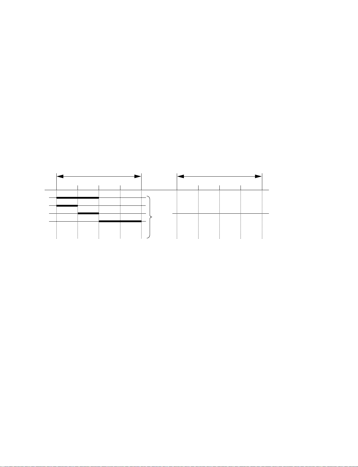
[Example]
When you want to delay an audio signal with reference to its video signal :
Test SG :ON
(Audio Test SG : Burst)
TP508
(VID-F)
TP509
(A-DET)
When you want to delay an audio signal with reference to the input video signal :
TP508
(VID-F)
TP509
(A-DET)
Delay : ON
Test SG : OFF
Delay : ON
Maximum delay amount is 4095 sample.
n
When the TEST SG is set to OFF, input the burst signal to identify the position relation of the external
input audio signal.
n
*: Refer to following table for sample to be adjusted.
Format Sample/Frame
1035i/60 1600
1035i/59.94 1601
1080i/60 1600
1080p/30sF 1600
1080i/59.94 1601
1080p/29sF 1601
1080i/50 1920
1080p/25sF 1920
1080p/24sF 2000
1080p/23.98sF 2002
720p/60 800
720p/59.94 800
HKSP-105
17 (E)
Page 20

6. Error/Warning
In this unit, the operations below are performed when an error or warning occurs.
. The output signal at pin 4 (BOARD ERROR OUT) or pin 5 (BOARD WARNING OUT) of the
STATUS OUT connector on the connector board of signal processing unit PFV-SP series becomes
active.
. The STATUS indicator on the operation panel blinks in red (error) or blinks in green (warning).
. A code appears on the display of the operation panel. (When ERR! or WRN! is selected in the system
menu.)
6-1. Error/Warning Code List
6-1-1. Error
Error code Contents of error
E- - - No error exists.
E-01 Hardware and software are not combined properly.
E-02 A connector board is not installed or different model’s is installed.
E-03 An error occurs by self-diagnosis at the time of starting.
6-1-2. Warning
Warning code Contents of warning
W- - - No warning exists.
W-01 No reference input signal exists or it is abnormal
W-02 An audio signal input is abnormal.
W-03 A video signal input is abnormal.
W-04 No video or audio signal exists.
18 (E)
HKSP-105
Page 21

6-2. Self-diagnosis Mode Error Code List
Error code Contents of error
E-OK No error exists.
E-01 NVRAM error
E-02 COPRO error
E-03 PLD1 error
E-04 PLD2 error
E-05 AUDIO_Pro1 error
E-06 AUDIO_Pro2 error
E-07 No video signal exists.
E-08 No audio signal exists.
E-09 COPRO status is abnormal.
E-10 PLD1 status is abnormal.
E-11 PLD2 status is abnormal.
E-12 AUDIO_Pro1 status is abnormal.
E-13 AUDIO_Pro2 status is abnormal.
7. Bypass Output
When the main board (DPR-214A board) is not installed, an HDTV SDI video input signal is directly
output to the SDI OUT connectors.
n
In bypass mode, audio multiplex becomes disabled.
HKSP-105
19 (E)
Page 22

8. Specifications
General
Performance guaranteed temperature +10 dC to +35 dC
Function guaranteed temperature +5 dC to +40 dC
Storage temperature _20 dC to +60 dC
Operating humidity 10 % to 90 % (Non-condensing)
Maximum outer dimensions Main board: 398 x 119 x 18 mm
(Width (W)/height (H)/depth (D)) Connector board: 153 x 130 x 19 mm
Mass Main board: Approx. 400 g
Connector board: Approx. 220 g
Power requirements +12 V dc: 0.8 A or less
Power consumption 9.6 W
Input/Output
SDI IN (BNC type) (1) HDTV SDI signal (Conforms to SMPTE 291M/292M/299M)
Level 0.8 V p-p ±10 %
Input impedance 75 Z, unbalanced
Input return loss 15 dB or more (5 MHz to 1.485 GHz)
Signal transmission distance 100 m (when using a 5C-FB coaxial cable)
SDI OUT (BNC type) (2) HDTV SDI signal (Conforms to SMPTE 291M/292M/299M)
Output amplitude 0.8 V p-p ±10 %
Output impedance 75 Z, unbalanced
Output return loss 15 dB or more (5 MHz to 1.485 GHz)
AES IN (BNC type) (4)
Input impedance 75 Z, unbalanced
Input return loss 25 dB or more (0.1 to 6.0 MHz)
SYSTEM DELAY 1.5 us or less
20 (E)
HKSP-105
Page 23

Page 24

The material contained in this manual consists of
information that is the property of Sony Corporation.
Sony Corporation expressly prohibits the duplication of
any portion of this manual or the use thereof for any
purpose other than the operation or maintenance of the
equipment described in this manual without the express
written permission of Sony Corporation.
Le matériel contenu dans ce manuel consiste en
informations qui sont la propriété de Sony Corporation.
Sony Corporation interdit formellement la copie de
quelque partie que ce soit de ce manuel ou son emploi
pour tout autre but que des opérations ou entretiens de
l’équipement à moins d’une permission écrite de Sony
Corporation.
Das in dieser Anleitung enthaltene Material besteht aus
Informationen, die Eigentum der Sony Corporation sind.
Die Sony Corporation untersagt ausdrücklich die
Vervielfältigung jeglicher Teile dieser Anleitung oder den
Gebrauch derselben für irgendeinen anderen Zweck als
die Bedienung oder Wartung der in dieser Anleitung
beschriebenen Ausrüstung ohne ausdrückliche
schriftliche Erlaubnis der Sony Corporation.
HKSP-105 (SY) J, E
3-690-407-11
Printed in Japan
Sony Corporation 2003. 10 08
B&P Company ©2003
 Loading...