

Sony HKCU-FP2,HSCU300RF,HSCU300R Operation Manual

HD CAMERA CONTROL UNIT
HSCU300RF
HSCU300R
CCU CONTROL PANEL
HKCU-FP2
OPERATION MANUAL [English]
1st Edition

Table of Contents
Overview .................................................................... 3
Features ..........................................................................3
System Configuration Example
(HSCU300RF, Optical Digital Transmission) .............. 5
System Configuration Example
(HSCU300R, Digital Triax Transmission) ....................6
Locations and Functions of Parts ........................... 7
Front Panel ..................................................................... 7
Rear Panel ...................................................................... 8
HKCU-FP2 CCU Control Panel (Optional) ................... 10
Status Display ......................................................... 12
Displaying the Status Screen ........................................ 12
Status Display Screen .................................................. 12
Setup Menu.............................................................. 16
Changing Menu Item Settings ......................................16
Menu Tree .................................................................... 17
Menu List ...................................................................... 19
Appendix.................................................................. 29
Notes on Use ................................................................ 29
Digital Triax Transmission (HSCU300R) ...................... 29
Error messages ............................................................ 30
License Declarations .................................................... 30
Specifications ................................................................30
Table of Contents
2

Overview
Audio input/outputs
• Microphone (analog) output, 2-system (XLR-3-pin)
• Intercom input/output, 2-system (D-sub 25-pin)
• PGM (program audio) input, 2-system (D-sub 25-pin)
• The HSCU300RF Camera Control Unit connects to a Sony
HSC300RF or HSC100RF HD color camera via an optical
fiber cable. It performs signal processing, provides an
interface for external equipment, and supplies power to the
camera.
• The HSCU300R Camera Control Unit connects to a Sony
HSC300R or HSC100R HD color camera via a triaxial cable.
It performs signal processing, provides an interface for
external equipment, and supplies power to the camera.
The CCU features a down converter which converts HD
1)
signals
return video up converter which converts SD signals to HD
signals.
1) HD (High Definition) signal: Name for 1125/750-line HDTV signals
2) SD (Standard Definition) signal: Name for NTSC/PAL, 525/625
The CCU can be combined with an RCP-1000-series Remote
Control Panel (optional) to form a camera control system. The
CCU can also be combined with an MSU-1000/1500 Master
Setup Unit (optional), by installing the HZCU-MC3 multicamera control system software, to form a multi-camera
application system controlling multiple cameras.
In addition, an HKCU-FP2 CCU Control Panel (optional) can
be mounted on the front panel to form a simple remote control
system.
from a camera to SD signals2), and a simplified
component, and 525/625 composite signals
Features
Multi-system input/output interface
The CCU is equipped with the following input and output signal
connectors as standard equipment.
Video outputs
• SDI (main), 2-system (HD/SD selectable, embedded digital
audio)
• SDI (monitor), 2-system (HD/SD selectable, embedded
digital audio, superimposed character and marker display)
• Analog composite (VBS 2-system, PIX 1-system,
SYNC/WF 1-system)
• Analog component, 1-system (HD Y/Pb/Pr, HD R/G/B, SD
Y/R-Y/B-Y, SD R/G/B 4-format selectable)
• SYNC/WF 1-system (HD/SD selectable)
Other input/outputs
• Tally (R/G) (D-sub 25-pin)
• Microphone remote (D-sub 25-pin)
• WF (waveform monitor) remote output (D-sub 25-pin)
• WF (waveform monitor) mode output (D-sub 25-pin)
• Trunk (D-sub 25-pin)
• REMOTE (8-pin)
• LAN (RJ-45, 8-pin)
Note
The WF remote output, WF mode output, trunk, and microphone
remote share a common 25-pin connector.
External sync signals
The CCU can be locked to an external sync signal. Either an
HD tri-level sync signal or an SD sync (black burst) signal can
be used as the sync signal.
Optical digital transmission (HSCU300RF)
HD video signals can be transmitted up to 2 km (1 1/4 miles)
between a camera and the CCU over an optical fiber cable.
Digital Triax Transmission (HSCU300R)
The CCU and camera are connected using the industrystandard double-shielded triaxial camera cable (commonly
referred to as triax). The camera and CCU are equipped with
the latest Sony-developed digital transmission technology
which can transmit high-resolution pictures between the
camera and CCU.
Built-in down converter
HD signals from the camera can be converted to highresolution SD component SDI output signals using the
wideband down converter. The output signal aspect ratio can
be set to 4:3 edge crop, 16:9 squeeze, or letterbox. The down
converted SD signal has independent image enhancement,
gamma, and matrix functions that can be controlled externally.
Built-in simplified up converter
SD signal return video is displayed in the HD viewfinder using
a simple up converter. The return video aspect ratio can be set
to 4:3 edge crop, 16:9 squeeze, or letterbox.
Note
The analog composite (WF1 system) and SYNC1 system share a
single connector.
Video inputs
• Reference input (HD/SD support)
• SDI return input, 2-system (HD/SD selectable)
• VBS return input, 2-system
• VBS prompter input, 2-system
(HSCU300RF can transfer only one selected VBS prompter
input system to the camera.)
Electric shock prevention
A safety function cuts the high-voltage supply from the CCU if
the connection to the camera becomes unsafe.
When power is applied, low-voltage power is first supplied to
the camera. After the connected camera is correctly identified
using tone signal detection, the regular DC180 V high-voltage
power is supplied to the camera. Power is not supplied to
cameras not connected via a dedicated camera connection
cable.
Alarm indicators are also fitted to indicate cable open-circuit
and short-circuit conditions.
Overview
3

Wide range of audio functions
The CCU is fitted with two-channel microphone output, video
signals with embedded audio, and PGM (program) audio
input/output connectors. It also features an intercom system
with two independent channels, and supports four-wire and
RTS/Clear-Com intercom systems.
For information on support for RTS/Clear-Com systems,
contact a Sony service or sales representative.
Microphone volume control
The camera’s microphone volume can be controlled via the
MIC REMOTE connector.
Character monitor signal output
The self-diagnosis status screens and setup menu can be
output as a text character display on the video output signal.
See “Video outputs” on page 3.
Rack mountable
The CCU can be installed in a standard EIA 19-inch rack. The
height of the unit is 1.5U.
Optional accessories
You can add new functions by incorporating the following
optional accessories.
For information about installing optional accessories, contact
a Sony service or sales representative.
HKCU-FP2 CCU Control Panel
This control panel can be mounted on the CCU in place of the
front panel.
It provides adjustment of basic functions using the operation
switches and volume control.
HZCU-MC3 support software for multi-camera
control systems
Installing this optional accessory enables support for multicamera control systems.
4
Overview
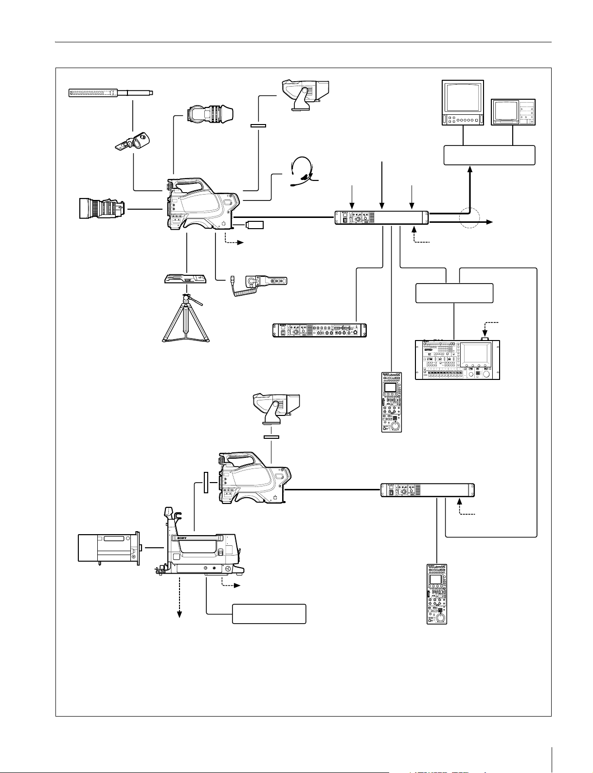
System Configuration Example (HSCU300RF, Optical Digital Transmission)
Microphone
CAC-12
Microphone
Holder
Zoom Lens
(for ENG/EFP)
Tr i po d fo r
portable camera
VCT-14
Tripod Adaptor
HDVF-200/C35W
Viewfinder
HSC300RF
HSC100RF
HD Color Camera
VF attachment shoe
Intercom headset
Optical fiber cable
USB drive
Power supply for a
script light
CAC-6
Return Video Selector
(mounts on front panel)
HKCU-FP2 Front
Control Panel
HDVF-550/C550W/C730W
Viewfinder
b)
Return video input
Sync input
HSCU300RF
Camera
Control Unit
CCA-5 cable
Prompter
video input
LAN cable
LAN cable
Picture Monitor
Wavefor m M on itor
BNC BNC
Video router
Video output
HD-SDI/SD-SDI/VBS
to router/
switcher
AC power
Hub
AC power
Zoom Lens
(for studio use)
VF attachment shoe
Camera hangers
General-purpose power supply
DC 12 V (Max. 5 A)
c)
d)
HDVF-550/C550W/C730W
Viewfinder
Remote Control Panel
b)
HSC300RF
HD Color Camera
Optical fiber cable
HDLA1500-series
Large Lens Adaptor
Power supply for a script light
BKP-7911
Script Holder
RCP-1000-series
RCP-1000-series
Remote Control Panel
MSU-1000/1500 Master
Setup Unit
HSCU300RF
Camera Control Unit
CCA-5 cable
a)
LAN cable
AC power
a) Supported only when using the multi-camera option
b) Supplied with the HDVF-550/C550W/C730W, Part No.: A-7612-405-E
c) Supplied with the HDLA1500/1505, Part No.: A-1128-405-A
d) For general-purpose DC 12 V output, the serial number must be
the following or higher :
HDLA1500: 13001 or 43001, HDLA1503: 52001,
HDLA1505: 11001, 41001 or 401001, HDLA1507: 401001
Overview
5

System Configuration Example (HSCU300R, Digital Triax Transmission)
Microphone
CAC-12
Microphone
Holder
Zoom Lens
(for ENG/EFP)
VCT-14
Tripod Adaptor
Tr i po d fo r
portable camera
HDVF-200/C35W
Viewfinder
HSC300R
HSC100R
HSC-300
HXC-100
HD Color Camera
VF attachment shoe
Intercom
headset
Triax cable
Power supply for a
script light
c)
USB drive
CAC-6
Return Video Selector
(mounts on front panel)
HKCU-FP2 Front
Control Panel
HDVF-550/C550W/C730W
Viewfinder
b)
Return video input
Sync input
HSCU300R
Camera
Control Unit
CCA-5 cable
Prompter
video input
LAN cable
LAN cable
Picture Monitor
Waveform Monitor
BNC BNC
Video router
Video output
HD-SDI/SD-SDI/VBS
to router/
switcher
AC power
Hub
AC power
HDVF-550/C550W/C730W
Viewfinder
RCP-1000-series
Remote Control Panel
VF attachment shoe
Camera hangers
Zoom Lens
(for studio use)
General-purpose power supply
DC 12 V (Max. 5 A)
a) Supported only when using the multi-camera option
b) Supplied with the HDVF-550/C550W/C730W, Part No.: A-7612-405-E
c) Minimum of 50 m (164 ft) up to a maximum of 900 m (2953 ft) when an HSC300R
or HSC-300 is connected or maximum of 600 m (1969 ft) when an HSC100R or
HXC-100 is connected using Fujikura 8.5-mm dia. cables.
When using other cables, see “Triax transmission distances (when an
HSC300R/HSC-300 is connected)” on page 29 or “Triax transmission distances
(when an HSC100R/HXC-100 is connected)” on page 29.
d)
e)
b)
HSC300R
HSC-300
HD Color Camera
Triax cable
HDLA1500-series
Large Lens Adaptor
Power supply for a script light
BKP-7911
Script Holder
MSU-1000/1500 Master
Setup Unit
HSCU300R
c)
Remote Control Panel
d) Supplied with the HDLA1500/1505, Part No.: A-1128-405-A
e) For general-purpose DC 12 V output, the serial number must
Camera Control Unit
AC power
CCA-5 cable
RCP-1000-series
be the following or higher:
HDLA1500: 13001 or 43001, HDLA1503: 52001,
HDLA1505: 11001, 41001 or 401001, HDLA1507: 401001
a)
LAN cable
6
Overview
Locations and Functions of Parts
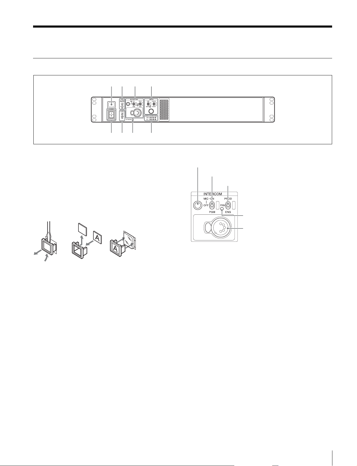
Front Panel
a
bc d
ef hg
a Tally light
Turns on red to indicate a red tally signal is being received
(such as when the picture from the camera connected to the
CCU is being used). When the CALL button on the camera,
the MSU-1000/1500 Master Setup Unit, or the RCP-1000series Remote Control Panel is pressed, the light turns off if lit
or turns on if not lit.
Turns on green to indicate a green tally signal is being
received.
A number plate supplied with the CCU can be attached (see
the following figure).
b CABLE ALARM indicators
OPEN: Turns on when a camera is not connected (open
circuit) to the CAMERA connector on the rear panel via an
optical fiber cable or a triax cable. While on, the CCU does
not supply any power to the camera.
It flashes if there is a transmission error between the
camera and CCU.
SHORT: Turns on when there is an overcurrent condition
(short circuit) on the optical fiber cable or triax cable. While
on, the CCU does not supply any power to the camera.
c INTERCOM audio input/output and control block
INTERCOM (intercom adjustment) knob
MIC/PGM (microphone/program) switch
INTERCOM (intercom select) switch
PRIV indicator
INTERCOM connector
• INTERCOM (intercom adjustment) knob
Adjusts the headset audio level.
• MIC/PGM (microphone/program) switch
ON: Turns the headset microphone on.
OFF: Turns the headset microphone off.
PGM: Selects program audio output.
• INTERCOM (intercom select) switch
Selects the intercom signal input/output connection source for
the INTERCOM connector on the rear panel.
PROD: Connects the producer line.
PRIV: Disconnects both the producer line and engineer line,
allowing private communication between CCU and camera
only.
ENG: Connects the engineer line.
• PRIV indicator
Turns on when the intercom is in private mode.
• INTERCOM connector (XLR 5-pin)
Intercom headset connection.
Locations and Functions of Parts
7
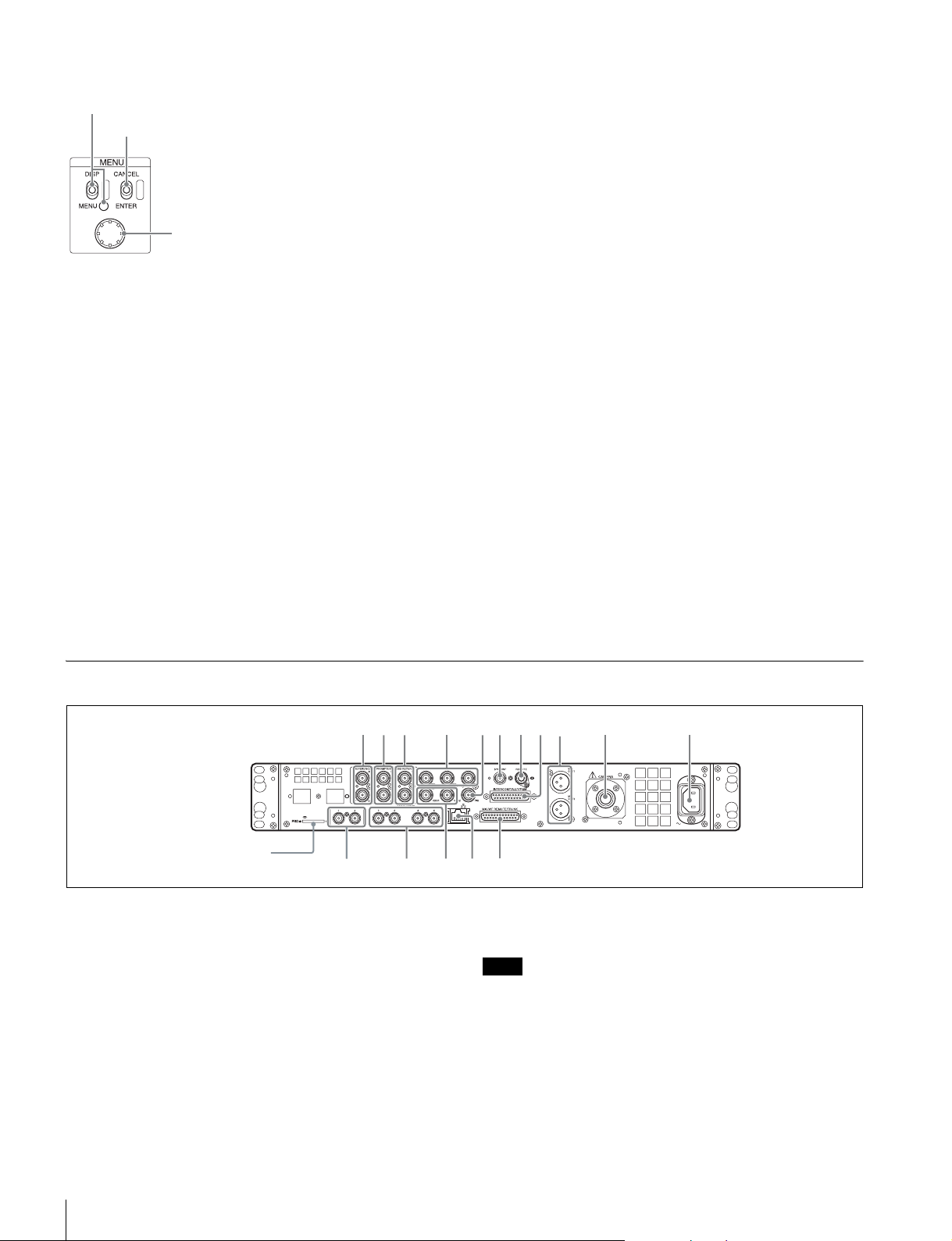
d MENU control block
DISP/MENU (display/menu) lever and indicator
CANCEL/ENTER lever
Control knob
• DISP/MENU (display/menu) lever and indicator
Selects the status display or setup menu display. In setup
menu mode, the indicator turns on.
• CANCEL/ENTER lever
In setup menu mode, used to cancel and enter settings.
• Control knob (rotary encoder)
In status screen mode, used to change the displayed page. In
setup menu mode, used to move the cursor on a page and to
change menu settings.
Pressing the control knob performs the same function as
setting the CANCEL/ENTER lever to the ENTER position.
e POWER switch
Switches the power for the entire system on and off, including
the CCU, camera, and the RCP-1000-series Remote Control
Panel connected to the REMOTE connector on the rear panel.
Pressing the “?” side turns the camera system on, and
pressing the “a” side turns it off.
f POWER indicator
CAM: Turns on when power is supplied to the camera.
MAIN: Turns on when the CCU power supply is turned on. It
flashes when there is a problem with the fan.
g NETWORK indicator
Displays the network system connection status.
On: Indicates that external control equipment
(MSU-1000/1500 Master Setup Unit, RCP-1000-series
Remote Control Panel, or other device) is connected.
Flashing: Indicates a connection problem with the external
control equipment (MSU-1000/1500 Master Setup Unit,
RCP-1000-series Remote Control Panel, or other device).
Off: Indicates that a LAN cable is not connected or that the
network system connection parameters have not been set.
See “Network diagnostics” on page 14 and “NETWORK
SETTINGS menu” on page 28.
h CABLE CONDITION indicators
Indicates the communication status of the camera (CAM) and
camera control unit (CCU).
When the two lamps on the right (green) are lighted:
Reception status is excellent.
When the second lamp from the right (green) is lighted:
Reception status is good.
When the second lamp from the left (yellow) is lighted:
Reception status is low.
When the lamp on the left (red) is lighted: Reception status
is at the lowest level.
• On the HSCU300RF, determined by the receive level of the
optical signal on the camera and CCU.
• On the HSCU300R, determined by the receive level of the
RF signal on the CCU.
Rear Panel
abc
Memory stick slot (for use
by service personnel only)
a REFERENCE IN/OUT (reference input) connectors
(BNC type)
Inputs an HD tri-level reference sync signal or SD reference
sync signal (black burst signal) on either of the two connectors.
The input signal is output from the other connector as-is (loopthrough output). The signal is input on the upper connector.
The lower connector is terminated automatically if no
connector is connected.
lomn p
dgfheij k
HSCU300RF diagram shown.
b PROMPTER 1, 2 (teleprompter input 1, 2) connectors
(BNC type)
Inputs the VBS signals for the teleprompter.
Note
On the HSCU300RF, only one system from the two systems on the
PROMPTER1 and 2 connectors is enabled.
c VBS RETURN 1, 2 (VBS return video 1, 2 input)
connectors (BNC type)
Inputs the 2-system VBS return video signals.
Locations and Functions of Parts
8

d Pr/R/R-Y, Y/G/Y, Pb/B/B-Y (component signals)
connectors (BNC type)
Outputs the HD component signals, SD component signals,
HD RGB signals, or SD RGB signals from the corresponding
connectors.
e PIX (picture monitor output) connector (BNC type)
Outputs a video signal for a picture monitor. It can also output
a signal with superimposed character display.
f SYNC/WF (sync signal output/waveform monitor
output) connector (BNC type)
Outputs a sync signal or video signal for a waveform monitor.
g REMOTE connector (8-pin)
Transmits and receives control signals from a MSU-1000/1500
Master Setup Unit, CNU-700 Camera Command Network
Unit, or RCP-1000-series Remote Control Panel via a CCA-5
cable (optional). It also supplies power when connected to an
RCP-1000-series Remote Control Panel.
h INTERCOM/TALLY/PGM (intercom/tally/program
audio) connector (D-sub 25-pin)
Transmits and receives the various intercom, tally, and
program audio signals. It connects to the
intercom/tally/program audio connector of the intercom
system.
i MIC OUT1, MIC OUT2 (microphone output 1, 2)
connectors (XLR 3-pin)
Outputs the camera microphone signals.
j CAMERA connector (optical fiber connector/triax
connector)
Connects to the camera via an optical fiber cable or a triax
cable. The camera sends all video and audio signals to the
CCU, and the CCU sends control signals, return video and
audio signals, as well as power, to the camera over a single
optical fiber cable or triax cable.
k AC supply input connector
Connects to the AC supply via the specified power cord
(optional). A plug holder (optional) can be used to secure the
power cord to the CCU.
o (LAN) jack (RJ-45, 8-pin)
Connects to a LAN hub (10BASE-T/100BASE-TX), when
using a network connection, via a LAN cable (shielded type,
category 5 or higher).
p MIC/WF REMOTE/TRUNK (microphone/waveform
monitor remote/trunk) connector (D-sub 25-pin)
Supports the following functions.
• Microphone remote
Connects to an external control device, such as an audio
mixer, which can select the camera microphone gain to one of
five values (20/30/40/50/60 dB) in response to the audio
conditions when shooting.
This connector can also output a red tally signal and green
tally signal.
• Waveform monitor remote
Connects to corresponding connector on a recall-type
waveform monitor.
Outputs a signal used for remote control of the waveform
monitor display by an MSU-1000/1500 Master Setup Unit or
RCP-1000 series Remote Control Panel.
For connection details, refer to the waveform monitor manual.
• Waveform monitor mode output
Connects to a waveform monitor and is used when monitoring
each of the 3 R/G/B waveforms simultaneously in sequential
mode.
When the SEQ button on the MSU-1000/1500 Master Setup
Unit or RCP-1000-series Remote Control Panel is pressed,
the video signal output from the WF connector changes to a
sequence signal.
•Trunk
Connects to an external device to provide a communication
path between it and the external device connected to the
REMOTE connector on the camera.
l SDI RETURN 1, 2 (SDI return video 1, 2 input)
connectors (BNC type)
Inputs the HD SDI return video signals or SD SDI return video
signals (2-system).
Can also be configured as the HD/SD SDI Prompter input
connector.
Note
The HSCU300RF does not support SDI Prompter.
m SDI OUTPUT 1 to 4 connectors (BNC type)
Outputs the camera signals in HD SDI or SD SDI signal
format.
The SDI OUTPUT 3 and SDI OUTPUT 4 connectors can also
output signals with superimposed character or marker display.
n VBS 1, 2 (composite video signal 1, 2) connectors
(BNC type)
Outputs (2-system) the camera signals in composite signal
format.
Locations and Functions of Parts
9
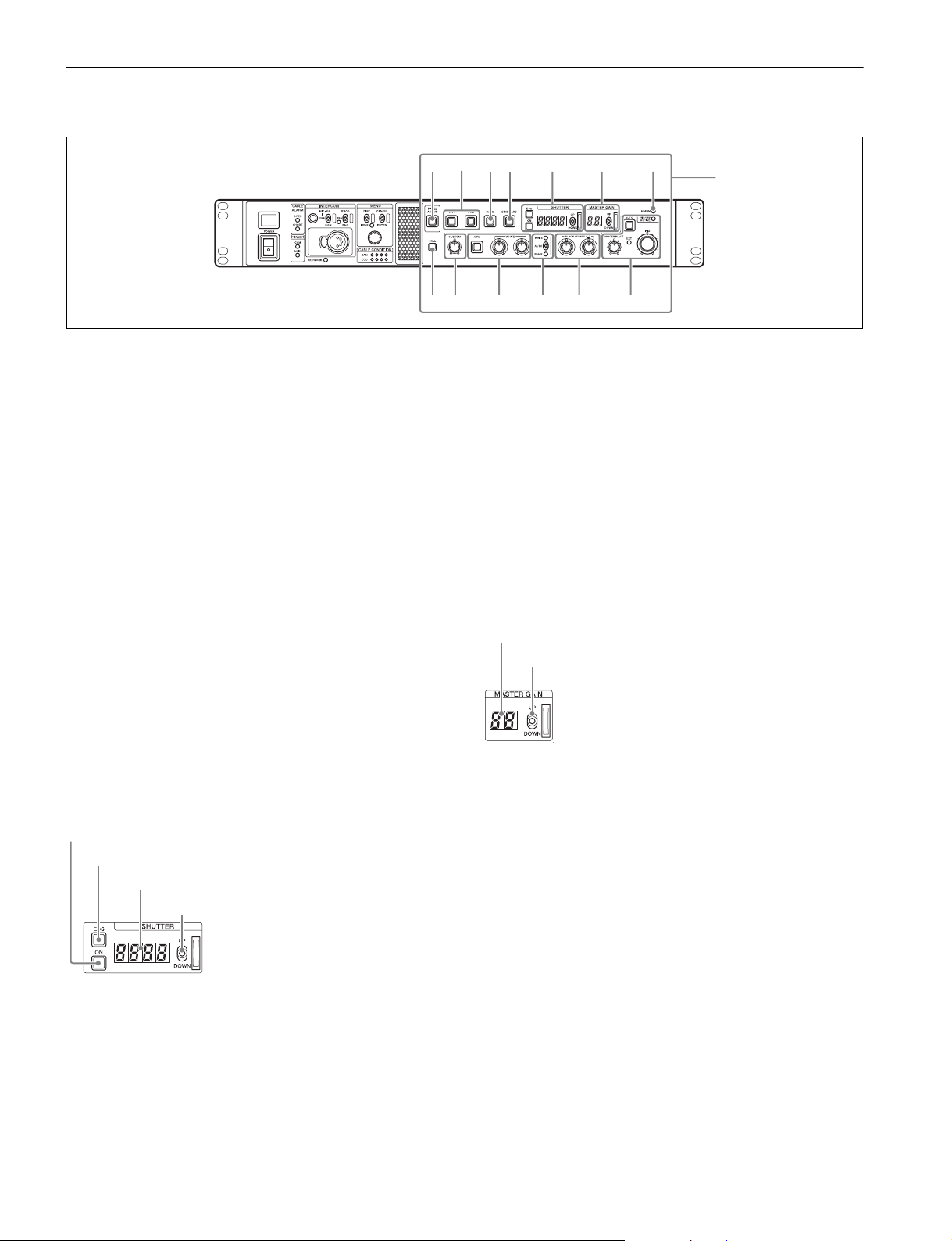
HKCU-FP2 CCU Control Panel (Optional)
The switches and knobs not described below are identical to those on the front panel. See “Front Panel” (page 7).
abcd e f g
hi j k l m
a PANEL ACTIVE button
Activates the optional HKCU-FP2 CCU Control Panel to
control the camera connected to the CCU (panel active state).
When the button is lit, the IRIS/MB ACTIVE indicator also
turns on simultaneously. When the button is not lit, the optional
panel is deactivated (lock state) to prevent inadvertent
operation.
b SW1, SW2 (assignable switch 1, 2) buttons
Controls the function assigned to each button on the <FRONT
PANEL 1> page in the CCU CONFIGURATION menu. The
button light turns on/off as the assigned function is switched
on/off.
See “ASSIGNABLE/CUSTOM” on page 26 on “<FRONT
PA N E L 1 > ” .
c BARS (color bars) button
Switches on the color bar signal output to the monitor
connected to the CCU (button light turns on). Pressing the
button again restores the previous signal output.
Optional panel controls
•Display
When the ECS button is lit: Displays the clear scan frequency.
When the ON button is lit: Displays the shutter speed.
•UP/DOWN lever
When the ECS button is lit: Adjusts the clear scan frequency.
UP increases the frequency, and DOWN decreases the
frequency.
When the ON button is lit: Adjusts the shutter speed. UP
increases the shutter speed, and DOWN decreases the
shutter speed.
Holding the lever UP or DOWN advances the setting in that
direction.
f MASTER GAIN controls
Controls the video output signal gain in response to the
lighting of the subject.
Display
UP/DOWN lever
d STANDARD button
Stores the current camera settings as the reference file data
values in the camera (button light turns on for a few seconds).
While the button is lit, pressing the button again cancels the
operation and restores the previous data values.
e SHUTTER controls
Controls the shutter settings.
ON button
ECS (extended clear scan) button
Display
UP/DOWN lever
• ON button
Switches the normal shutter function on/off (button light turns
on/off).
• ECS (extended clear scan) button
Switches the extended clear scan function on/off (button light
turns on/off).
•Display
Displays the video output signal gain setting (dB units).
•UP/DOWN lever
Adjusts the video output signal gain setting (dB units).
UP increases the gain, and DOWN decreases the gain.
Holding the lever UP or DOWN advances the setting in that
direction.
g ALARM indicator
Lights up red to indicate an error in the CCU or camera
system.
h CALL button
Sends a call signal to the camera connected to the CCU and
any external controller (such as the MSU-1000/1500 Master
Setup Unit or RCP-1000-series Remote Control Panel).
The CALL button is commonly used to raise the camera
operator or external control equipment operators on the
intercom.
Locations and Functions of Parts
10
i CUSTOM (custom volume) knob
Controls the function assigned to the knob on the <FRONT
PANEL 1> page in the CCU CONFIGURATION menu. Turning
the knob adjusts the assigned function.
See “VOLUME” on page 26 on “<FRONT PANEL 1>” and
“CUSTOM” on page 27 on “<FRONT PANEL 2>”.
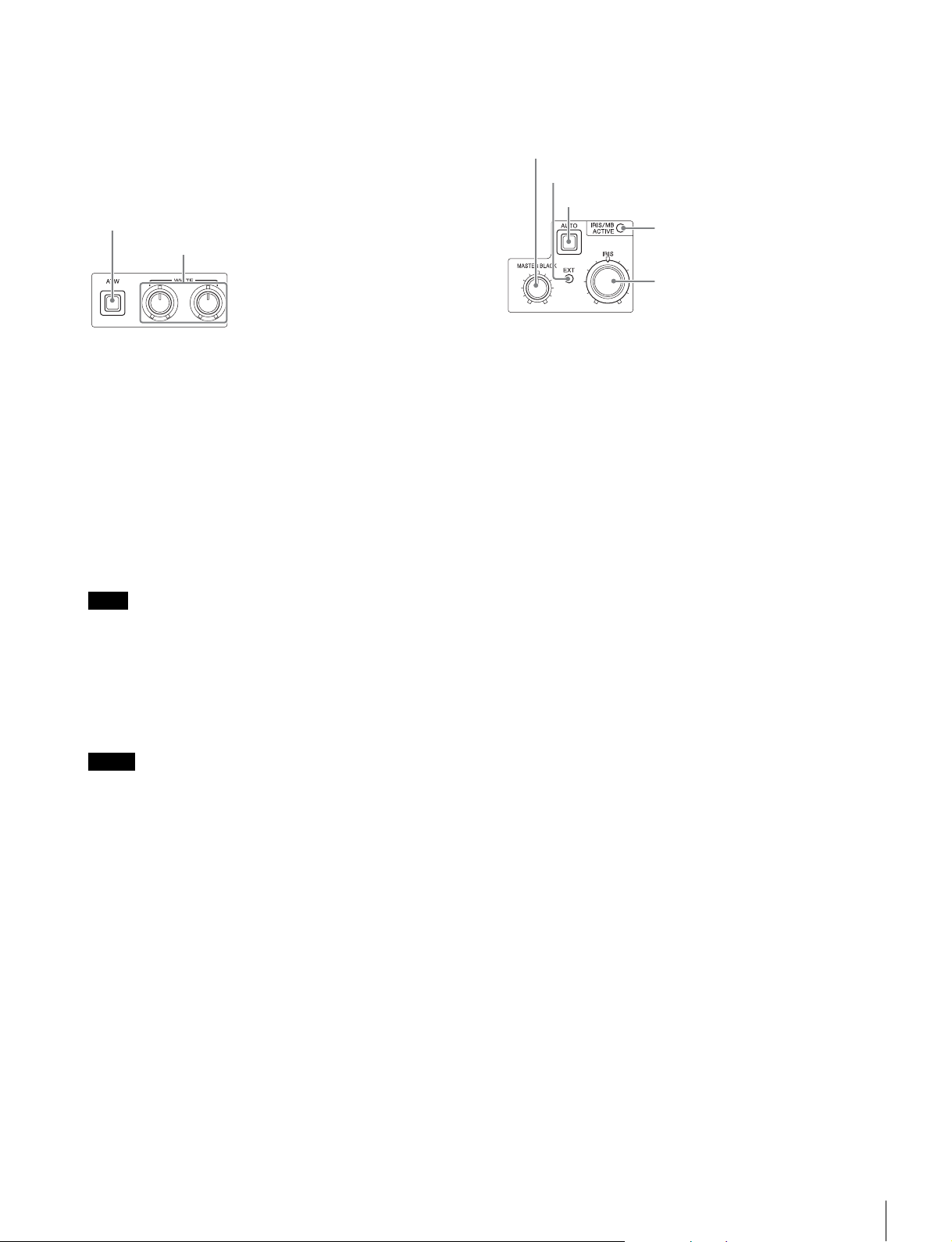
j White balance adjustment controls
ATW (auto tracing white balance) button
WHITE (white balance manual adjustment) knobs
See “R/B BLACK” on page 26 on “<FRONT PANEL 1>” and
“R/B BLACK” on page 27 on “<FRONT PANEL 2>”.
m IRIS/MASTER BLACK adjustment controls
MASTER BLACK (master black adjustment) knob
EXT (lens extender) indicator
AUTO (auto iris) button
IRIS/MB ACTIVE (iris/master black
active) indicator
IRIS (iris adjustment) knob
• ATW (auto tracing white balance) button
Switches the white balance auto adjustment function on/off
(button light turns on/off). The white balance is automatically
adjusted in response to the lighting conditions.
• WHITE (white balance manual adjustment) knobs
Adjusts the white balance manually. The left knob adjusts the
R coefficient, and the right knob adjusts the B coefficient.
The adjustment can be set to relative or absolute value mode
on the <FRONT PANEL 1> page in the CCU
CONFIGURATION menu. The default value is relative value
mode.
See “R/B WHITE” on page 26 on “<FRONT PANEL 1>” and
“R/B WHITE” on page 27 on “<FRONT PANEL 2>”.
Note
When the ATW button is lit, the WHITE knobs are deactivated.
k AUTO WHITE/BLACK (white balance/black balance
auto adjustment) lever
Initiates the white balance or black balance auto adjustment
function.
WHITE automatically adjusts the white balance, and BLACK
automatically adjusts the black balance.
Notes
• When the WHITE knobs are set to absolute value mode, the white
balance cannot be automatically adjusted using the AUTO
WHITE/BLACK lever.
• When the BLACK/FLARE indicator is not lit and the BLACK/FLARE
knobs are set to absolute value mode, the black balance cannot be
automatically adjusted using the AUTO WHITE/BLACK lever.
l BLACK/FLARE (black balance/flare balance manual
adjustment) knobs and indicator
Adjusts the black balance and flare balance manually.
When the indicator is not lit, the knobs adjust the black
balance. When the indicator is lit, the knobs adjust the flare
balance. The left knob adjusts the R coefficient, and the right
knob adjusts the B coefficient.
The indicator operating mode (on/off function) can be set on
the <FRONT PANEL 1> page in the CCU CONFIGURATION
menu.
The adjustment can be set to black balance or flare balance
adjustment in relative or absolute value mode on the <FRONT
PANEL 1> page in the CCU CONFIGURATION menu. The
default value is black balance adjustment in relative value
mode.
• MASTER BLACK (master black adjustment) knob
Adjusts the master black manually.
The adjustment can be set to relative or absolute value mode
on the <FRONT PANEL 1> page in the CCU
CONFIGURATION menu. The default value is relative value
mode.
See “M BLACK” on page 26 on “<FRONT PANEL 1>” and
“M BLACK” on page 27 on “<FRONT PANEL 2>”.
• EXT (lens extender) indicator
Turns on to indicate that the lens extender is in-use on the
camera.
• AUTO (auto iris) button
Switches the lens auto iris adjustment function on/off (button
light turns on/off). The iris is automatically adjusted in
response to the input light level.
When the button is not lit, the iris is adjusted manually.
• IRIS/MB ACTIVE (iris/master black active) indicator
Indicates, when lit, that the iris and master black controls are
active (in panel active state set by the PANEL ACTIVE button).
When the indicator is lit, the iris and master black can be
adjusted from the CCU.
• IRIS (iris adjustment) knob
When the AUTO button is not lit: Adjusts the lens iris manually.
When the AUTO button is lit: Finely adjusts the auto adjusted
iris value.
The adjustment can be set to relative or absolute value mode
on the <FRONT PANEL 1> page in the CCU
CONFIGURATION menu. The default value is relative value
mode.
See “IRIS” on page 26 on “<FRONT PANEL 1>” and “IRIS” on
page 27 on “<FRONT PANEL 2>”.
Locations and Functions of Parts
11
 Loading...