

Sony HXCU-100, HKCU-FP1 Service Manual

HD CAMERA CONTROL UNIT
HXCU-100
FRONT CONTROL PANEL
HKCU-FP1
SERVICE MANUAL
1st Edition

!警告
このマニュアルは,サービス専用です。
お客様が,このマニュアルに記載された設置や保守,点検,修理などを行うと感電や火災,
人身事故につながることがあります。
危険をさけるため,サービストレーニングを受けた技術者のみご使用ください。
! WARNING
This manual is intended for qualifi ed service personnel only.
To reduce the risk of electric shock, fi re or injury, do not perform any servicing other than that
contained in the operating instructions unless you are qualifi ed to do so. Refer all servicing to
qualifi ed service personnel.
! WARNUNG
Die Anleitung ist nur für qualifi ziertes Fachpersonal bestimmt.
Alle Wartungsarbeiten dürfen nur von qualifi ziertem Fachpersonal ausgeführt werden. Um die
Gefahr eines elektrischen Schlages, Feuergefahr und Verletzungen zu vermeiden, sind bei
Wartungsarbeiten strikt die Angaben in der Anleitung zu befolgen. Andere als die angegeben
Wartungsarbeiten dürfen nur von Personen ausgeführt werden, die eine spezielle Befähigung
dazu besitzen.
! AVERTISSEMENT
Ce manual est destiné uniquement aux personnes compétentes en charge de l’entretien. Afi n
de réduire les risques de décharge électrique, d’incendie ou de blessure n’effectuer que les
réparations indiquées dans le mode d’emploi à moins d’être qualifi é pour en effectuer d’autres.
Pour toute réparation faire appel à une personne compétente uniquement.
安全のために,周辺機器を接続する際は,過大電圧を持
つ可能性があるコネクターを以下のポートに接続しない
でください。
:LANコネクター
上記のポートについては本書の指示に従ってくだい。
For safety, do not connect the connector for peripheral
device wiring that might have excessive voltage to the
following port(s).
: LAN connector
Follow the instructions for the ports(s).
HXCU-100

注意
FÖRSIKTIGHET!
指定以外の電池に交換すると,破裂する危険があります。
必ず指定の電池に交換してください。
使用済みの電池は,国または地域の法令に従って
処理してください。
CAUTION
Danger of explosion if battery is incorrectly replaced.
Replace only with the same or equivalent type recommended by the manufacturer.
When you dispose of the battery, you must obey the
law in the relative area or country.
ATTENTION
Il y a danger d’explosion s’il y a remplacement incor-
rect de la batterie. Remplacer uniquement avec
une batterie du même type ou d’un type équivalent
recommandé par le constructeur.
Lorsque vous mettez la batterie au rebut, vous devez
respecter la législation en vigueur dans le pays ou la
région où vous vous trouvez.
Fara för explosion vid felaktigt placerat batteri.
Byt endast mot samma eller likvärdig typ av batteri,
enligt tillverkarens rekommendationer.
När du kasserar batteriet ska du följa rådande lagar
för regionen eller landet.
PAS PÅ
Fare for eksplosion, hvis batteriet ikke udskiftes
korrekt.
Udskift kun med et batteri af samme eller tilsvarende
type, som er anbefalet af fabrikanten.
Når du bortskaffer batteriet, skal du følge
lovgivningen i det pågældende område eller land.
HUOMIO
Räjähdysvaara, jos akku vaihdetaan virheellisesti.
Vaihda vain samanlaiseen tai vastaavantyyppiseen,
valmistajan suosittelemaan akkuun.
Noudata akun hävittämisessä oman maasi tai
alueesi lakeja.
VORSICHT
Explosionsgefahr bei Verwendung falscher Batterien.
Batterien nur durch den vom Hersteller empfohlenen
oder einen gleichwertigen Typ ersetzen.
Wenn Sie die Batterie entsorgen, müssen Sie die
Gesetze der jeweiligen Region und des jeweiligen
Landes befolgen.
For kundene i Norge
Dette utstyret kan kobles til et IT-strømfordelingssystem.
FORSIKTIG
Eksplosjonsfare hvis feil type batteri settes i.
Bytt ut kun med samme type eller tilsvarende
anbefalt av produsenten.
Kasser batteriet i henhold til gjeldende avfallsregler.
HXCU-100
1 (P)

Attention-when the product is installed in Rack:
1. Prevention against overloading of branch circuit
When this product is installed in a rack and is supplied
power from an outlet on the rack, please make sure
that the rack does not overload the supply circuit.
2. Providing protective earth
When this product is installed in a rack and is supplied
power from an outlet on the rack, please confi rm that
the outlet is provided with a suitable protective earth
connection.
3. Internal air ambient temperature of the rack
When this product is installed in a rack, please make
sure that the internal air ambient temperature of the
rack is within the specifi ed limit of this product.
4. Prevention against achieving hazardous condition
due to uneven mechanical loading
When this product is installed in a rack, please make
sure that the rack does not achieve hazardous condition due to uneven mechanical loading.
5. Install the equipment while taking the operating
temperature of the equipment into consideration
For the operating temperature of the equipment, refer
to the specifi cations of the Operation Manual.
6. When performing the installation, keep the following space away from walls in order to obtain proper
exhaust and radiation of heat.
Rear: 10 cm (4 inches) or more
Right, Left: 4 cm (1.6 inches) or more
Top: 4 cm (1.6 inches) or more
2 (P)
HXCU-100

Table of Contents
Manual Structure
Purpose of this manual ............................................................3 (E)
Related manuals ...................................................................... 3 (E)
Trademarks .............................................................................. 3 (E)
1. Installation
1-1. Connectors and Cables ..............................................1-1 (E)
1-1-1. Connector Input/Output Signals ......................1-1 (E)
1-1-2. Wiring Diagrams for Cables ............................1-5 (E)
1-1-3. Connection Connectors/Cables ........................ 1-5 (E)
1-2. Location of Printed Circuit Boards ...........................1-6 (E)
1-3. Outside Dimensions ..................................................1-6 (E)
1-4. Installing the HKCU-FP1 .......................................... 1-7 (E)
1-5. Description of Onboard LED Indicators ...................1-8 (E)
1-6. Switch Settings .......................................................1-10 (E)
1-7. Potentiometer Functions ......................................... 1-12 (E)
1-8. Mounting the Unit in a 19-Inch Rack......................1-13 (E)
3. System Setup
3-1. System Connection .................................................... 3-1 (E)
3-2. Audio System ............................................................3-2 (E)
3-2-1. Intercom System Setting ..................................3-2 (E)
3-2-2. Microphone Setting..........................................3-6 (E)
3-3. System Settings ......................................................... 3-7 (E)
3-3-1. Tally System Setting ........................................3-7 (E)
3-3-2. Camera Number Setting...................................3-7 (E)
3-4. Video Signal System .................................................3-8 (E)
3-4-1. Input/Output Signal Selection .......................... 3-8 (E)
3-4-2. Signal Phase Adjustment ................................. 3-8 (E)
3-4-3. Aspect Ratio Setting for Down-Conversion ....3-9 (E)
3-4-4. VBS Signal Level Adjustment ....................... 3-11 (E)
3-4-5. Waveform Monitor Signal Level Adjustment ... 3-11 (E)
3-4-6. Stair Case Signal Adjustment Procedure .......3-12 (E)
3-4-7. Picture Monitor Signal Level Adjustment .....3-13 (E)
3-4-8. RETURN Input Signal ................................... 3-13 (E)
4. Maintenance Mode
2. Service Overview
2-1. Service Information ................................................... 2-1 (E)
2-1-1. Tools .................................................................2-1 (E)
2-1-2. Note on Replacement of Lithium Battery ........ 2-1 (E)
2-2. Connecting/Disconnecting the Flexible Card Wire ....2-2 (E)
2-3. Upgrading the Software Programs ............................2-3 (E)
2-3-1. Upgrading the Main Program .......................... 2-3 (E)
2-3-2. Upgrading the Boot Program ...........................2-4 (E)
2-4. Writing and Rewriting the PLD Internal Data .......... 2-5 (E)
2-5. Periodic Replacement Parts ....................................... 2-6 (E)
2-6. Notes on Replacement of Circuit Board ...................2-6 (E)
2-6-1. EEPROM Data ................................................. 2-6 (E)
2-6-2. Actions to Be Taken during Board Replacement
and after Board Replacement/Repair .................. 2-6 (E)
2-7. Circuit Protective Devices ......................................... 2-7 (E)
2-8. How to Extend Boards ..............................................2-8 (E)
2-8-1. Horizontal Extension .......................................2-8 (E)
2-8-2. Vertical Extension .......................................... 2-11 (E)
2-9. Circuit Description ..................................................2-14 (E)
2-10. Notes on Repair Parts ..............................................2-20 (E)
2-11. Unleaded Solder ...................................................... 2-20 (E)
4-1. Preparations ...............................................................4-1 (E)
4-1-1. Starting/Exiting the Maintenance Mode ..........4-1 (E)
4-1-2. Memory Stick ..................................................4-1 (E)
4-2. VE OPERATION Menu ............................................4-2 (E)
4-3. MAINTENANCE Menu ......................................... 4-12 (E)
5. Replacement of Main Parts
5-1. Removing/Installing the Front assembly...................5-1 (E)
5-2. Replacing the DC Fan ............................................... 5-1 (E)
5-3. Removing/Installing the Rear Panel Assembly ......... 5-2 (E)
5-4. Replacing the TRIAX connector assembly ...............5-3 (E)
5-5. Replacing Boards ...................................................... 5-4 (E)
5-5-1. AU-321 Board/CN-3083 Board ....................... 5-4 (E)
5-5-2. CN-3080 Board ................................................ 5-5 (E)
5-5-3. CN-3081 Board ................................................ 5-6 (E)
5-5-4. CN-3082 Board ................................................ 5-7 (E)
5-5-5. CT-257 Board................................................... 5-7 (E)
5-5-6. DPR-300 Board ...............................................5-8 (E)
5-5-7. DY-23 Board ....................................................5-9 (E)
5-5-8. ENC-112 Board ...............................................5-9 (E)
5-5-9. FL-349 Board ................................................. 5-10 (E)
HXCU-100
1 (E)

5-5-10. MB-1124 Board .............................................5-12 (E)
5-5-11. PS-739 Board .................................................5-13 (E)
5-5-12. SDI-97 Board .................................................5-14 (E)
5-5-13. SY-364 Board ................................................. 5-14 (E)
5-5-14. VIF-39 Board .................................................5-15 (E)
8. Block Diagrams
Overall ............................................................................. 8-2
9. Schematic Diagrams
6. Electrical Alignment
6-1. Preparations ...............................................................6-1 (E)
6-1-1. Equipment Required ........................................ 6-1 (E)
6-1-2. Precautions on Adjustments .............................6-1 (E)
6-1-3. Connection of Equipment ................................6-2 (E)
6-1-4. Initial Settings ..................................................6-2 (E)
6-2. Audio System Adjustment .........................................6-3 (E)
6-2-1. RTS Intercom Adjustment Check .................... 6-3 (E)
6-3. Video/Reference Signal System Adjustment.............6-5 (E)
6-3-1. 27 MHz VCO Free-Running Adjustment ........6-5 (E)
6-3-2. STAIR CASE Adjustment ...............................6-5 (E)
6-4. SD Signal System Adjustment ..................................6-6 (E)
6-4-1. VBS Output Level Adjustment ........................ 6-6 (E)
6-4-2. PIX Output Level Adjustment .........................6-6 (E)
6-4-3. WF Output Level Adjustment ..........................6-7 (E)
6-4-4. Y/R-Y/B-Y Output Level Adjustment (SD) ....6-8 (E)
6-5. HD Signal System Adjustment ..................................6-9 (E)
6-5-1. Y/R-Y/B-Y Output Level Adjustment (HD).... 6-9 (E)
6-5-2. RGB Output Level Adjustment......................6-10 (E)
6-6. TRIAX Transmission System Adjustment .............. 6-11 (E)
6-6-1. 1.0-MHz Modulation Circuit Adjustment ...... 6-11 (E)
6-6-2. 1.4-MHz Demodulation Circuit
Adjustment ..................................................... 6-12 (E)
6-6-3. Tone Detection Frequency Adjustment .......... 6-13 (E)
7. Spare Parts
7-1. Notes on Repair Parts ......................................................7-1
7-2. Exploded Views ...............................................................7-2
7-3. Electrical Parts List .........................................................7-7
7-4. Supplied Accessories .....................................................7-84
7-5. Optional Fixtures ........................................................... 7-84
AU-321 ............................................................................9-2
CN-3080 .......................................................................... 9-3
CN-3081 .......................................................................... 9-4
CN-3082 .......................................................................... 9-6
CN-3083 .......................................................................... 9-6
DPR-300 ..........................................................................9-7
DY-23 ............................................................................ 9-43
ENC-112 ........................................................................ 9-48
FL-349 ........................................................................... 9-50
MB-1124 ....................................................................... 9-51
SDI-97 ........................................................................... 9-54
SY-364 ........................................................................... 9-56
VIF-39 ........................................................................... 9-74
LED-473 ........................................................................ 9-75
SW-1413 ........................................................................ 9-76
Frame Wiring................................................................. 9-78
10. Board Layouts
AU-321 .......................................................................... 10-2
CN-3080 ........................................................................ 10-3
CN-3081 ........................................................................ 10-4
CN-3082 ........................................................................ 10-5
CN-3083 ........................................................................ 10-5
DPR-300 ........................................................................ 10-6
DY-23 .......................................................................... 10-11
ENC-112 ...................................................................... 10-11
FL-349 ......................................................................... 10-12
MB-1124 ..................................................................... 10-12
SDI-97 ......................................................................... 10-13
SY-364 ......................................................................... 10-14
VIF-39 ......................................................................... 10-18
LED-473 ...................................................................... 10-19
SW-1413 ...................................................................... 10-19
2 (E)
HXCU-100

Purpose of this manual
Related manuals
Manual Structure
This manual is the service manual for HD Camera Control Unit HXCU-100 and
Front Control Panel HKCU-FP1.
This manual describes the information items that premise the service based on the
components parts such as main parts replacement, electrical alignment, schematic
diagrams, board layouts and detailed parts list assuming use of system and service
engineers.
Besides this service manual the following manual is available for this unit.
. HXCU-100 Operating Instructions (Supplied with HXCU-100)
This manual is necessary for application and operation of HXCU-100.
Part number: 4-140-418-0X (Japanese)
Part number: 4-140-418-1X (English)
. HXCU-100 Operating Instructions CD-ROM (Supplied with HXCU-100)
This manual is necessary for application and operation of HXCU-100.
The CD-ROM contains the English, French, German, Italian, and Spanish operating
instructions (PDF).
Part number: 4-140-420-0X
Trademarks
. “Semiconductor Pin Assignments” CD-ROM (Available on request)
This “Semiconductor Pin Assignments” CD-ROM allows you to search for semiconductors used in Broadcast and Professional equipment.
This manual contains a complete list of semiconductors and their ID Nos., and thus
should be used together with the CD-ROM.
Part number: 9-968-546-06
Trademarks and registered trademarks used in this manual are follows.
. FRAM is a registered trademark of Ramtron International Corporation.
HXCU-100
3 (E)


Section 1
Installation
1-1. Connectors and Cables
1-1-1. Connector Input/Output Signals
Input/Output Signals (TRIAX)
Name Description
CAMERA VIDEO, RET VIDEO, INCOM, MIC, COMMAND, PROMPTER, PGM, TRUNK, TONE,
POWER
Input Signals (BNC)
Name Description
PROMPTER Analog composite signals: 1.0 V p-p, 75 Z
REFERENCE HD or SD
HD: SMPTE 274M, tri-level sync, 0.6 V p-p, 75 Z
SD: Black burst signal
NTSC: 0.286 V p-p, 75 Z
PAL: 0.3 V p-p, 75 Z
RETURN INPUT
SDI 1/3, SDI 2/4
RETURN INPUT
VBS 1/3, VBS 2/4
HD SDI or SD SDI
HD SDI: SMPTE 292M, 0.8 V p-p, 75 Z , 1.485 Gbps/1.4835 Gbps
BTA-S004B compliant
SD SDI: SMPTE 259M, 270 Mbps
Component serial signal
Analog composite signals: 1.0 V p-p, 75 Z
Output Signals (BNC)
Name Description
PIX 1.0 V p-p, 75 Z
Pr/R/R-Y, Y/G/Y,
Pb/B/B-Y
SDI OUTPUT
1 to 4
SYNC HD: BTA-S001A, tri-level sync, 0.6 V p-p, 75 Z
VBS OUTPUT 1, 2 1.0 V p-p, 75 Z
WF 0.714 V p-p, 75 Z (NTSC)
. HD component video
Y/Pb/Pr: 0.7 V p-p, 75 Z
. HD RGB video
R/G/B: 0.7 V p-p, 75 Z
. SD RGB video
R/G/B: 0.7 V p-p, 75 Z
. SD component video (NTSC, 75 % color-bar)
Y: 1.0 V p-p (VIDEO:0.714 V, SYNC:0.286 V), 75 Z
R-Y/B-Y: 0.756 V p-p, 75 Z (J)
0.7 V p-p, 75 Z (UC)
. SD component(PAL, 75 % color-bar)
Y: 1.0 V p-p (VIDEO:0.7 V, SYNC:0.3 V), 75 Z
R-Y/B-Y: 0.525 V p-p, 75 Z
HD SDI: SMPTE 292M, 0.8 V p-p, 75 Z, 1.485 Gbps/1.4835 Gbps
BTA-S004B compliant
SD SDI: SMPTE 259M, 0.8 V p-p, 75 Z, 270 Mbps
Component serial signal
HD SDI or SD SDI selectable
SD: composite sync, 0.3 V p-p, 75 Z
HD SYNC/SD SYNC selectable
0.7 V p-p, 75 Z (PAL)
ENC : 1.0 V p-p, 75 Z
HXCU-100
1-1 (E)
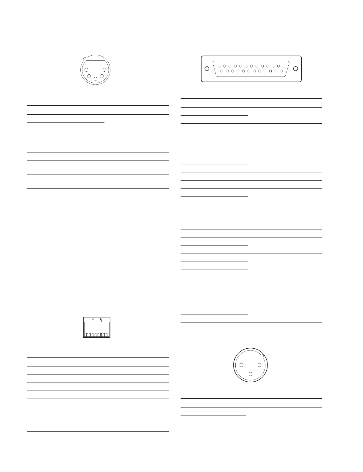
INTERCOM (XLR 5P, Female)
INTERCOM/TALLY/PGM (D-sub 25P, Female)
5
1
2
4
3
- EXT VIEW -
(0 dBu = 0.775 Vrms)
No. Signal Specifi cations
1 INTERCOM MIC IN (Y)
2 INTERCOM MIC IN (X)
_20 dBu
(CARBON UNBALANCE)
_40 dBu
(ECM, UNBALANCE)
_60 dBu (DYNAMIC,
BALANCE/UNBALANCE)
3 GND GND for INTERCOM
4 INTERCOM L OUT 8 dBu (VR Max, 250 Z
Load)
5 INTERCOM R OUT 8 dBu (VR Max, 250 Z
Load)
LAN (8P, RJ-45, 10Base-T/100Base-TX)
113
25 14
- EXT VIEW -
(0 dBu = 0.775 Vrms)
No. Signal Specifi cations
1 ENG (R) (X) OUT ENG SYSTEM RECEIVE
2 ENG (R) (Y) OUT
0 dBu BALANCED
3 ENG (G) GND for ENG
4 ENG (T) (X) IN ENG SYSTEM TALK
5 ENG (T) (Y) IN
6 PGM1 (X) IN
7 PGM1 (Y) IN
0 dBu BALANCED
_20 dBu/0 dBu/+ 4 dBu
(Selectable with CCU Menu)
8 PGM1 (G) IN
9 GND GND for AUX
10 AUX3
11 R TALLY (X) IN ON:24 Vdc, TTL (H), SHORT
12 R TALLY (Y) IN
OFF:0 Vdc, TTL (L), OPEN
13 GND CHASSIS GND
14 PROD (R) (X) OUT PROD SYSTEM RECEIVE
15 PROD (R) (Y) OUT
0 dBu BALANCED
16 PROD (G) GND for PROD
17 PROD (T) (X) IN PROD SYSTEM TALK
18 PROD (T) (Y) IN
19 PGM2 (X) IN
20 PGM2 (Y) IN
0 dBu BALANCED
_20 dBu/0 dBu/+ 4 dBu
(Selectable with CCU Menu)
21 PGM2 (G) IN
22 EML
*
PIX/WF
OUTPUT
Active:GND
THROUGH (OFF):OPEN
23 EML Enable Enable:GND
Normal (Disable) :OPEN
24 G TALLY (X) IN ON:24 Vdc, TTL (H), SHORT
25 G TALLY (Y) IN
*: Easy Monitor Link function
OFF:0 Vdc, TTL (L), OPEN
18
- EXT VIEW -
No. Signal Specifi cations
1 TX (+) Transmitted Data (+)
2 TX (_) Transmitted Data (_)
3 RX (+) Received Data (+)
4 NC No connection
5 NC No connection
6 RX (_) Received Data (_)
7 NC No connection
8 NC No connection
1-2 (E)
MIC OUT 1, 2 (XLR 3P, Male)
12
3
- EXT VIEW -
(0 dBu = 0.775 Vrms)
No. Signal Specifi cations
1 MIC OUT (G) 0 dBu/_ 20 dBu
2 MIC OUT (X)
3 MIC OUT (Y)
(Selectable with CCU Menu)
HXCU-100

MIC REMOTE (D-sub 15P, Female)
18
15 9
- EXT VIEW -
No. Signal Specifi cations
1
+ 5.5 V OUT
2 TALLY GND GND for TALLY
3 G TALLY OUT ON (GND) : Max. 30 mA IN
4 R TALLY OUT ON (GND) : Max. 30 mA IN
5 CAM MIC AMP GAIN CTRL2 IN
6 CAM MIC AMP GAIN CTRL1 IN
7
CAM MIC AMP GAIN CTRL0 IN
Max. 250 mA
CTRL 0 CTRL 1 CTRL 2 CAM MIC AMP GAIN
H H H 60 dB
L H H 50 dB
H L H 40 dB
L L H 30 dB
H H L 20 dB
8 MIC1 GAIN CTRL ON/OFF IN
8pin 15pin MIC GAIN CTRL
L L MIC 1 and 2 ON
L H MIC 1 ON
H L MIC 2 ON
H H INTERNAL set
9 GND GND for +5.5 V
10 TALLY OUT R/G TALLY OUT
ON (GND) : Max. 30 mA IN
11 PREVIEW OUT ON (GND) : OPEN COLLECTOR
12 ASPECT REMOTE ON/OFF IN L : REMOTE
13 ASPECT CTRL1 IN
14 ASPECT CTRL2 IN
CTRL1 CTRL2 ASPECT
L H SQ (16:9)
H H EC (4:3)
L L INTERNAL set
HL LB
15 MIC2 GAIN CTRL ON/OFF IN
8pin 15pin MIC GAIN CTRL
L L MIC 1 and 2 ON
L H MIC 1 ON
H L MIC 2 ON
H H INTERNAL set
HXCU-100
1-3 (E)
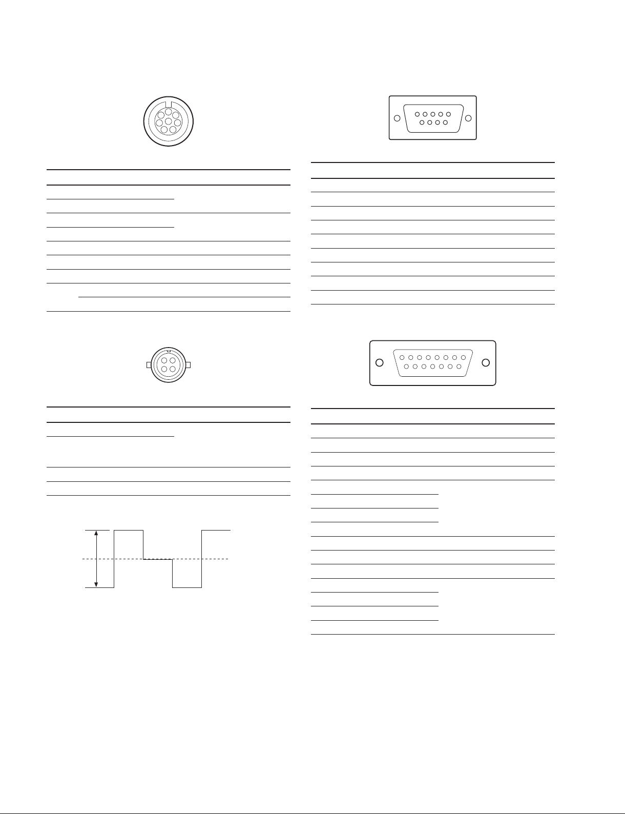
REMOTE (8P, Female)
TRUNK (D-sub 9P, Female, RS-422A)
1
2
7
8
6
3
5
4
- EXT VIEW -
No. Signal Specifi cations
1 TX (+) SERIAL DATA OUT
2 TX (_)
3 RX (+) SERIAL DATA IN
4 RX (_)
5 TX GND GND for TX
6 POWER (+) OUT RCP POWER, +30 V
7 POWER (_) OUT GND for POWER
8 VIDEO (X) 75 Ω, 1.0 V p-p
CHASSIS GND CHASSIS GND
WF MODE (4P, Female)
4
1
3
2
- EXT VIEW -
5
9
1
6
- EXT VIEW -
No. Signal Specifi cations
1 GND
2 RX (_) TRUNK Data in
3 TX (+) TRUNK Data out
4 GND
5 GND
6 GND
7 RX (+) TRUNK Data in
8 TX (_) TRUNK Data out
9 GND
WF REMOTE (D-sub 15P, Female)
18
15 9
- EXT VIEW -
No. Signal Specifi cations
1 SEQ CTRL OUT (G) OPEN COLLECTOR
2 SEQ CTRL OUT (X)
+(PNP)/_(NPN)
(Selectable with S2801/
DPR-300board)
3 STAIR CASE OUT (X)
*1
4 STAIR CASE OUT (G) GND for STAIR CASE
*1 : Stair Case signal
1
A
12 V
6
RG B
DC 0 r 2 V
No. Signal Specifi cations
1 NC No connection
2 NC No connection
3 NC No connection
4 NC No connection
5 RECALL2 (G) LOW ACTIVE
6 RECALL3 (B)
7 RECALL1 (R)
8 RECALL4 (SEQ)
9 GND
10 NC No connection
11 NC No connection
12 RECALL5 (ENC) LOW ACTIVE
13 RECALL6 (R+B)
14 RECALL7 (R+G)
15 RECALL8 (G+B)
1-4 (E)
HXCU-100

1-1-2. Wiring Diagrams for Cables
CCA-5 Cable (for REMOTE connector)
Black
White
Orange
White
Brown
INTERCOM MIC Cable
(1) Balance (BALANCE in MIC TYPE menu)
G
X
Y
INTERCOM
MIC
Red
White
Red
BrownBrown
— 8P CONNECTOR (MALE) —
(2) Unbalance (UNBALANCE in MIC TYPE menu)
X
Y
INTERCOM
MIC
(WIRING SIDE)
1-1-3. Connection Connectors/Cables
Connection made with the connector panels during installation or service, should be made with the connectors/complete
cable assemblies specifi ed in the following list, or equivalent parts.
Connector Name Connector/Cable
CAMERA (TRIAX)
PROMPTER
REFERENCE, SYNC
VBS OUTPUT 1, 2
PIX, WF
Pr/R/R-Y, Y/G/Y, Pb/B/B-Y
RETURN INPUT VBS 1/3, 2/4
(BNC)
SDI OUTPUT 1 to 4
RETURN INPUT SDI 1/3, 2/4
(BNC)
MIC OUT 1, 2 (3P, Male) 1-508-083-00 XLR 3P Female or CANNON XLR-3-11C equivalent
WF REMOTE (D-sub 15P, Female)
MIC REMOTE (D-sub 15P, Female)
INTERCOM/TALLY/PGM
(D-sub 25P, Female)
WF MODE (4P, Female) 1-560-155-00 PLUG, 4P Male (accessory)
REMOTE (8P, Female) 1-766-848-11 PLUG, 8P Male or CCA CABLE ASSY (optional) CCA-5-10 (10 m),
INTERCOM (5P, Female) 1-508-370-11 XLR 5P, Male or CANNON XLR-5-12C equivalent
TRUNK (D-sub 9P, Female) 1-568-182-11 D-sub 9P, Male or JAE DE-9PF-N equivalent
LAN (8P, RJ-45) LAN cable (commercially available, shield type, category 5 or higher)
. KINGS TRIAX (UC) connector
. Tajimi Electronics TRIAX (J) connector
. FISCHER TRIAX (CE) connector
1-564-742-11 PLUG, BNC or B-B Cable assembly (1.5 m, optional)
1-569-370-12 PLUG, BNC or 5C-FB coaxial cable (Fujikura products recommended)
1-506-582-11 D-sub 15P, Male or JAE DA-15PF-N equivalent
(Available shell: JAE DA-C1-J10-R equivalent)
1-766-367-11 D-sub 25P, Male JAE DB-25PF-N equivalent
(Available shell: JAE DB-C2-J9-R equivalent)
CCA-5-3 (3 m)
(Available shell: JAE DE-C1-J6-R equivalent)
HXCU-100
1-5 (E)
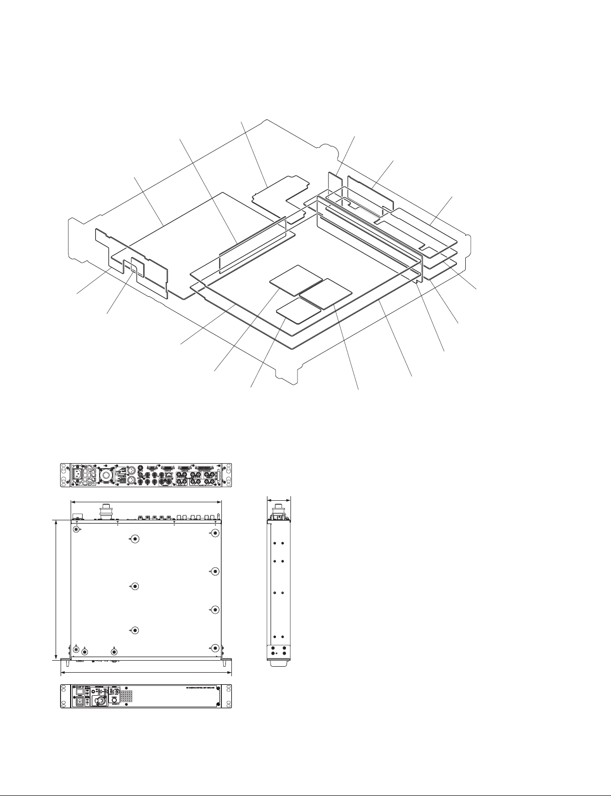
1-2. Location of Printed Circuit Boards
FL-349
CT-257
PS-739
CN-3082
CN-3080
SDI-97
AU-321
CN-3083
DPR-300
1-3. Outside Dimensions
424
DY-23
VIF-39
CN-3081
MB-1124
SY-364
DY-23ENC-112
66
395
1-6 (E)
482
Unit: mm
HXCU-100
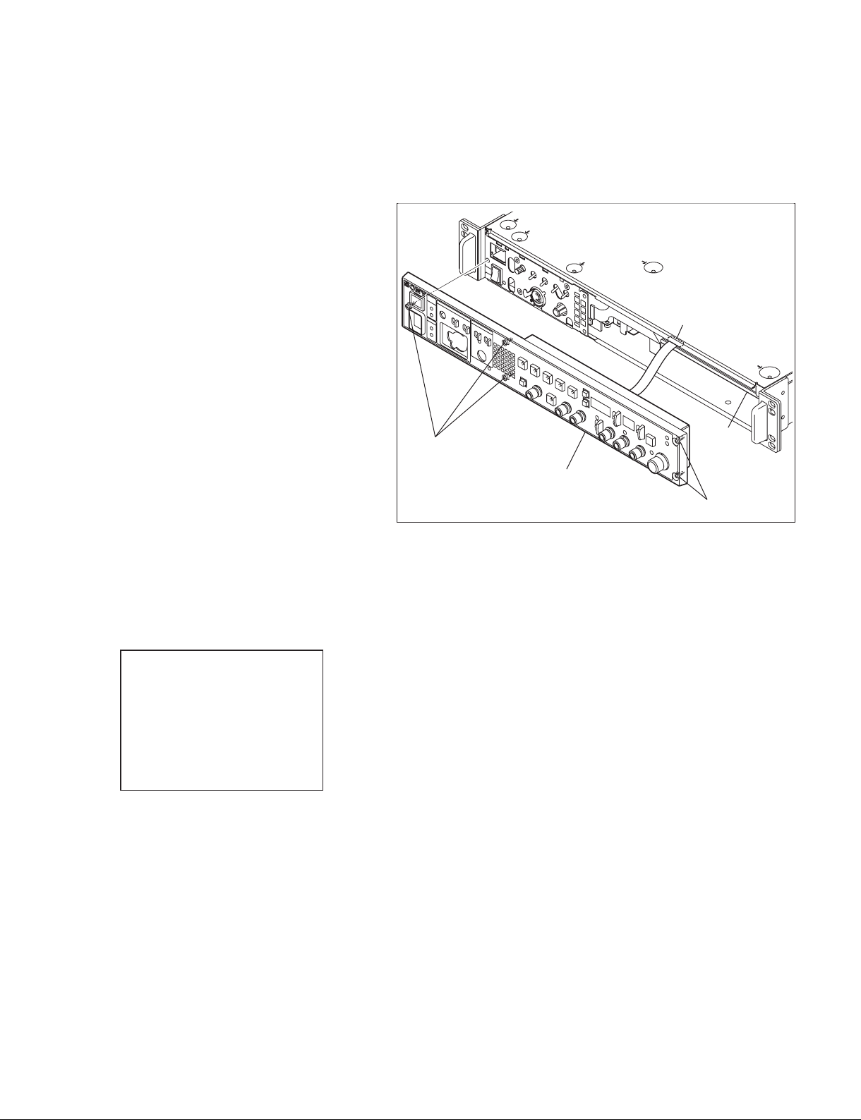
1-4. Installing the HKCU-FP1
1. Remove the front assembly.
(Refer to Section 5-1.)
2. Connect the fl exible card wire of the HKCU-FP1
to the connector CN2 on the SY-364 board.
n
Be careful not to bend the fl exible card wire.
This shortens the wire life.
3. Install the HKCU-FP1 with fi ve screws with
stopper.
4. Check that the HKCU-FP1 is recognized
correctly on the status screen.
n
Front Panel on the screen shows the status of
the HKCU-FP1.
%JBHOPTJT
%130,4%*0,
4:0,7*'0,
'SPOU1BOFM0,
Screws with stopper
CN2
SY-364
board
HKCU-FP1
Screws with stopper
HXCU-100
1-7 (E)
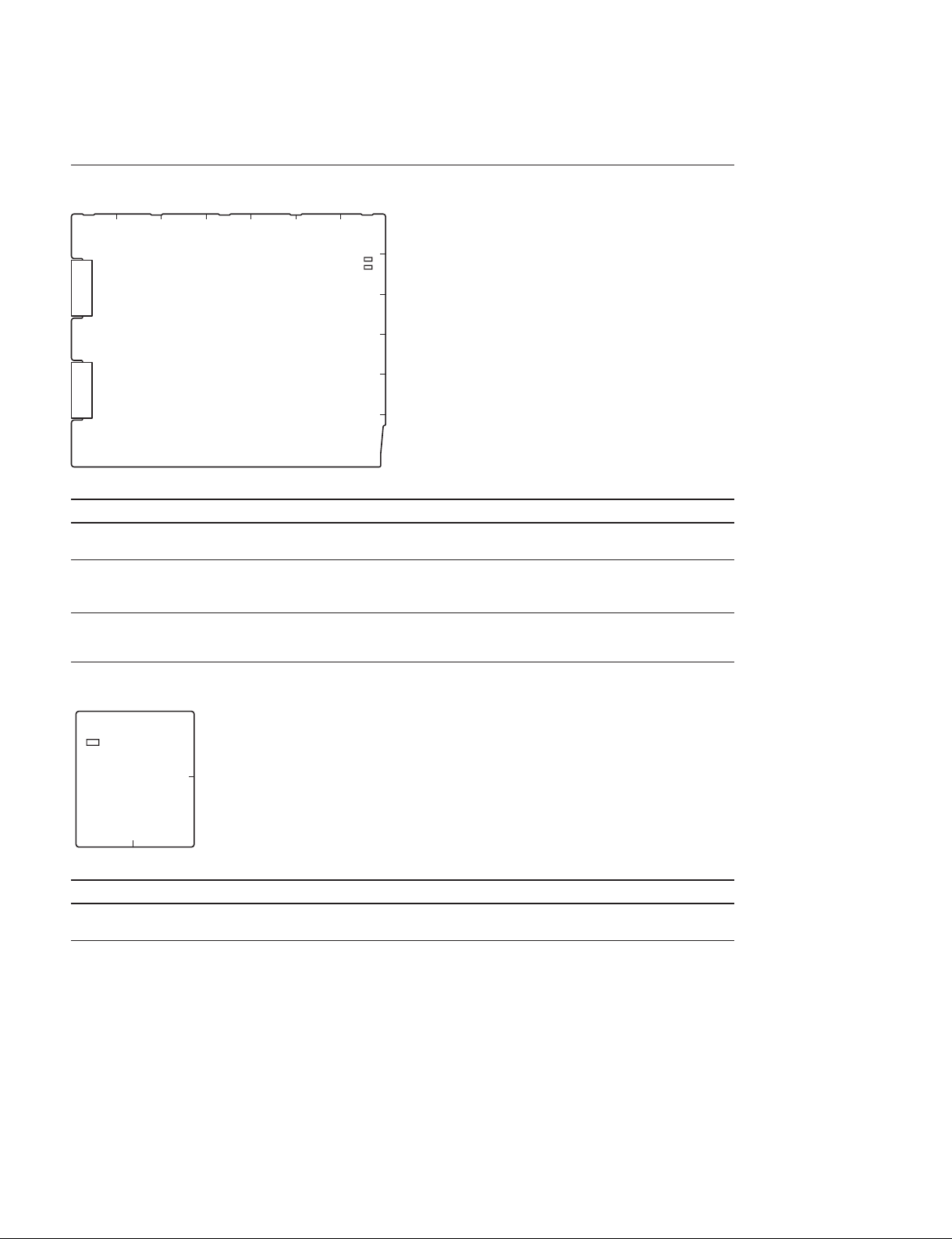
1-5. Description of Onboard LED Indicators
DPR-300 Board
BACDEFG
1
D406
2
D701
3
4
5
6
DPR-300 Board (SIDE A)
Ref.No. Name Color Description Normal state
D406 PWR Green Lights when all power voltages on the DPR-300 board are
Lit
normal.
D701 CONF Red Lights when there is a problem with the confi guration of any
Off
FPGA (IC700, IC1700, IC2000, or IC2400) on the DPR-300
board.
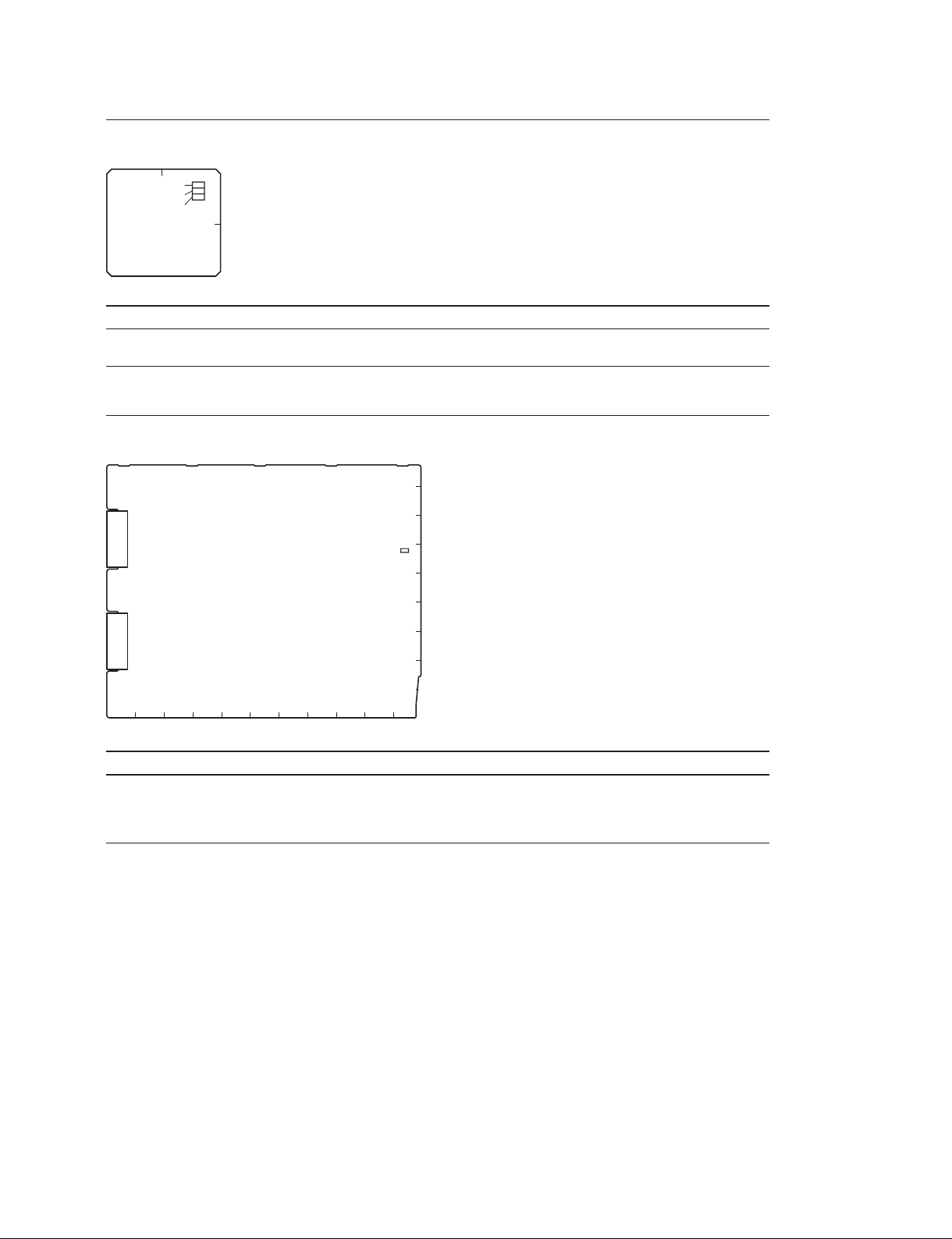
DY-23 Board
D102
DY-23 Board (SIDE B)
Ref.No. Name Color Description Normal state
D102 D7 Green Blinks slowly when IC201 on the DY-23 board functions
1
2
AB
Blinking
correctly.
1-8 (E)
HXCU-100
ENC-112 Board
AB
D100
D101
D102
1
2
ENC-112 Board (SIDE B)
Ref.No. Name Color Description Normal state
D100-102
_
Green Blinks when IC100 on the ENC-112 board functions
Blinking
correctly.
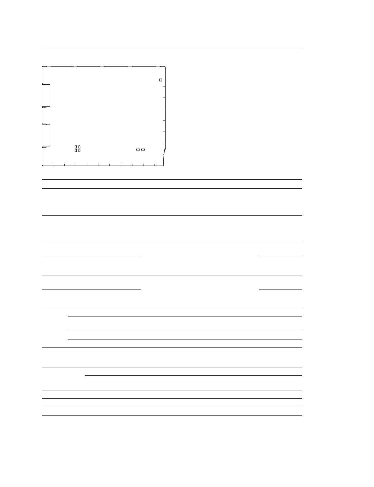
SY-364 Board
9
8
7
D808
6
5
4
3
2
1
L K J H G F E D CBA
SY-364 Board (SIDE A)
Ref.No. Name Color Description Normal state
D808 MS-LED Red/Green Indicates state of access to the memory stick
_
Lit red: Access to the memory stick in progress. Do
not remove the memory stick.
Lit green: The inserted memory stick can be removed.
HXCU-100
1-9 (E)

1-6. Switch Settings
n
Do not change the settings of unused switches.
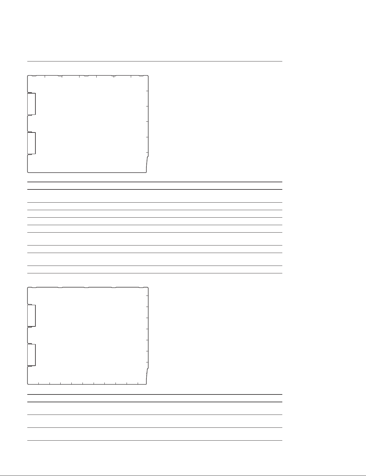
DPR-300 Board
BACDEFG
S2801
1
2
S2001
3
4
5
6
DPR-300 Board (SIDE A)
Ref.No. Name Bit Description Factory setting
S2001 CLEAN 1 Enables or disables the SDI monitor output (3, 4) charac-
OFF
ter mixing function.
OFF: Normal SDI monitor output
ON: SDI monitor output (3, 4) character and marker
are always OFF (Clean).
_
_
_
S2801 SEQ
2 Not used OFF
3 Not used OFF
4 Not used OFF
Switched according to the waveform monitor used.
_
_ (NPN)
_ (NPN): NPN open-collector output
+ (PNP): PNP open-collector output
1-10 (E)
HXCU-100
SY-364 Board
9
S801
8
7
6
5
4
3
S733S730
S734S731
L K J H G F E D CBA
SY-364 Board (SIDE A)
Ref.No. Name Bit Description Factory setting
S530 PROD SEL
Select an intercom system for the producer line.
_
4W: 4-wire system
RTS (CC): RTS or Clear-Com is selectable with
S531 ENG SEL
Select an intercom system for the engineer line.
_
4W: 4-wire system
RTS (CC): RTS or Clear-Com is selectable with
S730 R-TALLY
(POWER/CONTACT)
S733 R-TALLY
(POWER/TTL)
S731 G-TALLY
(POWER/CONTACT)
S734 G-TALLY
(POWER/ TTL)
Set these switches in accordance with the specifi -
_
cations for the R TALLY signal that is input to the
INTERCOM/TALLY/PGM connector on the rear
_
panel. For relationship of the signal and switch
settings, refer to the table below.
Set these switches in accordance with the specifi -
_
cations for the G TALLY signal that is input to the
INTERCOM/TALLY/PGM connector on the rear
_
panel. For relationship of the signal and switch
settings, refer to the table below.
S801 PROTECT 1 Used to protect data write to IC801. ON
VerUp 2 Used to enable software upgrade using a memory
stick.
NORMAL/DEBUG 3 Not used OFF
NORMAL/DEBUG 4 Not used OFF
2
S530S531
1
4W
the CCU menu.
4W
the CCU menu.
CONTACT
TTL
CONTACT
TTL
OFF
Tally System Settings
Ref.No. Red tally Green tally
S730
(POWER/ CONTACT)
Contact supply CONTACT
24 V supply POWER POWER POWER POWER
5 V supply POWER TTL POWER TTL
HXCU-100
S733
(POWER/TTL)
_
S731
(POWER/ CONTACT)
CONTACT
S734
(POWER/TTL)
_
1-11 (E)
1-7. Potentiometer Functions
DPR-300 Board
LV1501 RV1501
11
RV1502
RV1503
1
1
LV1502
1
1
LV1503
BACDEFG
RV2602
RV2601
1
2
1
1
3
4
5
6
DPR-300 Board (SIDE A)
Ref.No. Name Description
RV1501 DEV ADJ Adjusts modulation degree of standby INCOM (CCU to CAM) FM-modulated wave
output.
RV1502 ST INCOM LEV ADJ Adjusts waveform level of standby INCOM (CAM to CCU) demodulation output.
RV1503 TONE ADJ. Adjusts free-running oscillation frequency of the TONE signal detection circuit.
RV2601 DC (Position) Adjusts lateral display position of tri-waveform display on the waveform monitor.
RV2602 LEVEL (Interval) Adjusts display position interval of tri-waveform display on the waveform monitor.
LV1501 1.0M FREQ ADJ Adjusts modulation frequency of standby INCOM (CCU to CAM) FM-modulated
wave.
LV1502 TUNE 1 Adjusts operating point of the standby INCOM (CAM to CCU) demodulation circuit.
LV1503 TUNE 2 Adjusts output distortion of the standby INCOM (CAM to CCU) demodulation
circuit.
SY-364 Board
9
8
7
6
RV531
1
5
1
RV530
4
3
2
RV1
L K J H G F E D CBA
1
SY-364 Board (SIDE A)
Ref.No. Name Description
RV1 27M FREQ Adjusts free-running oscillation frequency of 27M-VCO (X1) for readjustment required
when it is replaced.
RV530 PROD RTS CANCEL Adjusts sidetone cancellation amount of the producer line when RTS or Clear-Com
is connected.
RV531 ENG RTS CANCEL Adjusts sidetone cancellation amount of the engineer line when RTS or Clear-Com
is connected.
1
1-12 (E)
HXCU-100

1-8. Mounting the Unit in a 19-Inch Rack
This unit can be mounted in a 19-inch EIA standard rack (height: 1.5U).
w
. Secure the rack to the fl oor.
If the rack falls due to the weight of equipment, it may result in death or serious injury.
Secure the rack to the fl oor without fail to prevent it from falling or moving.
. Do not mount the unit at a fl oor height of more than 1 m.
Fall of the rack may result in death or serious injury.
Mount the unit in the rack that is secured to the fl oor at a fl oor height within about 1 m.
Preparations
c
Be sure to use specifi ed rack-mount rails.
If unspecifi ed rack-mount rails are used, the equipment in the rack may fall due to insuffi cient strength,
which may result in injury.
[Part] [Quantity]
. Slide rail [1 set]
Accuride Japan Model 305A-18 (457 mm)
. Front bracket [2]
Sony Part No.: 2-142-214-01
. Rear bracket [2]
Sony Part No.:2-142-215-01
. Screw (B4 x 8) [14]
. Screw (B5 x 8) [8]
. Screw (PWH4 x 20) [2]
. Nut [2]
. Plate nut [2]
Sony Part No.: 3-651-812-00
. Rack mount rail screw (PSW5 x 25): [4]
Manufacturer: Accuride Japan
HXCU-100
1-13 (E)
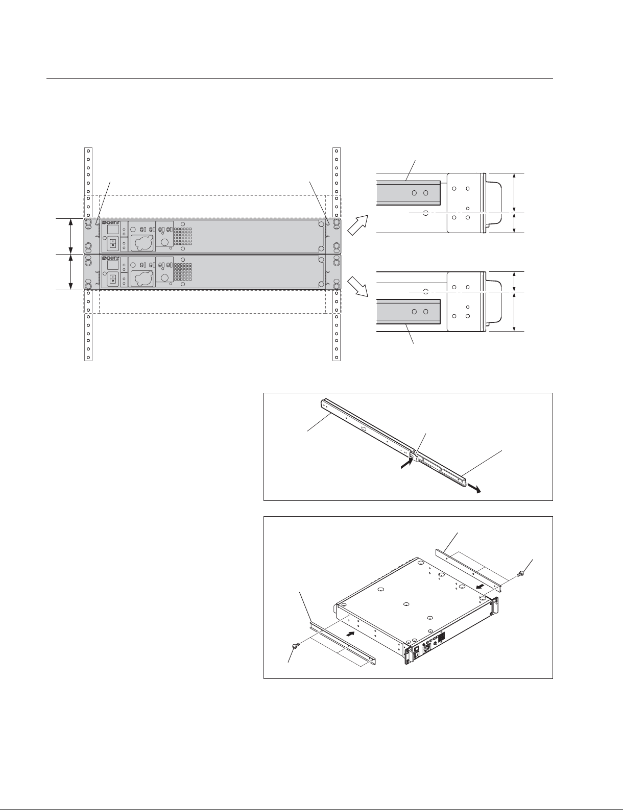
Mounting the Unit in the Rack
This unit is mounted in the rack by attaching the inner rails at the upper or lower part 1U of height 1.5U.
The rail attaching position varies depending on the unit mounting height in the rack.
When mounting this unit under other equipment,
install the inner rail at the upper part (1U) of the
unit.
Inner rail
1.5U
Inner rail
Other equipment
HXCU-100
1U
0.5U
1.5U
HXCU-100
Other equipment
1. Pull out the inner rail while pressing the rail
stopper.
2. Install the inner rail to the unit with six
screws (B4 x 8).
n
This fi gure shows attaching the inner rails at
the upper part.
The same method applies for attaching the
inner rails at the lower part.
Outer rail
Inner rail
0.5U
1U
When mounting this unit above other equipment,
install the inner rail at the lower part (1U) of the
unit.
Stopper
Inner rail
Inner rail
B4 x 8
1-14 (E)
B4 x 8
HXCU-100
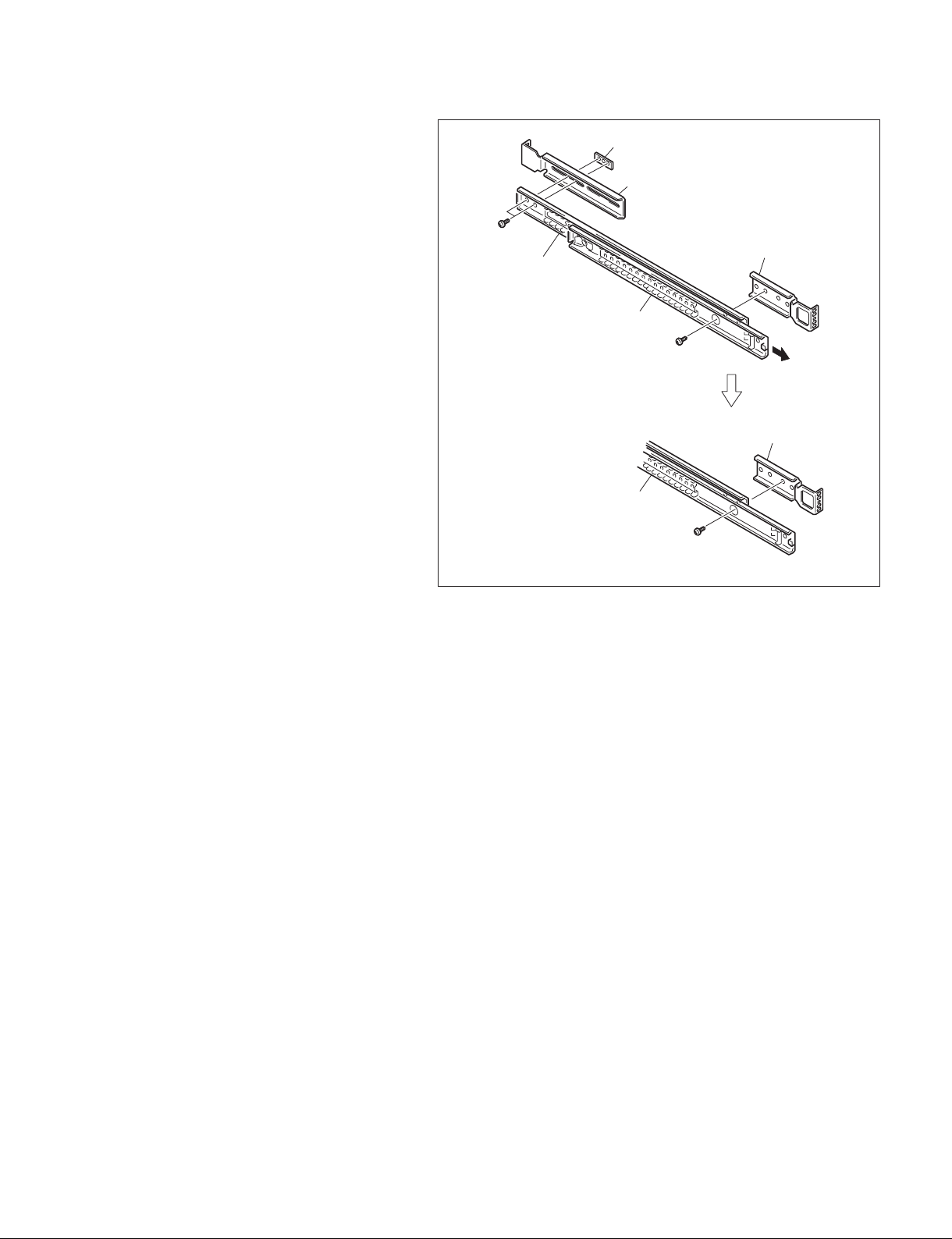
3. Attach the front and rear brackets to the outer
rail with eight screws (B4 x 8).
m
. When attaching the front bracket, slide the
middle member to the position where the
screw hole in the cabinet member is visible
from the hole in the middle member shown
in the fi gure.
. When attaching the rear bracket, adjust the
bracket position according to the depth of
the rack.
Plate nut
Rear bracket
B4 x 8
Front bracket
Cabinet member
Mid member
B4 x 8
Front bracket
Mid member
B4 x 8
HXCU-100
1-15 (E)

4. Attach the front bracket to the inside of the rack
mount position with two screws (PWH4 x 20).
31.75
Rack (front)
PWH4 x 20
Nut
When the inner rail is installed at the upper part (1U) of the
unit, attach the front bracket at this position.
Front bracket
Outer rail
12.7
31.75
12.7
31.75
Unit: mm
Inner rail
5. Attach the rear bracket to the outside of the
rack mount position with four screws (B5 x 8).
12.7
31.75
12.7
31.75
Inner rail
When the inner rail is installed at the lower part (1U) of the
unit, attach the front bracket at this position.
Rack (rear)
Outer rail
1-16 (E)
31.75
B5 x 8
B5 x 8
Rear bracket
Unit: mm
HXCU-100
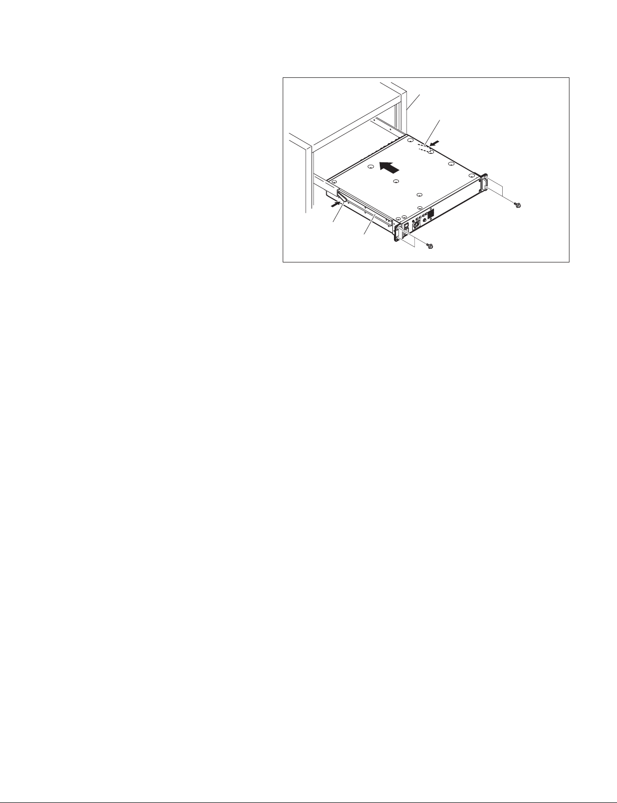
6. Set the unit in the rack while pressing the
inner rail stopper into the outer rail as far as it
will go.
m
. This rack mounting work must be done by
two or more workers so as not to hurt the
worker s waist.
. Failure to tighten the rack angle screws
may cause the unit to slide and fall from the
rack, resulting in injury. After the unit has
been mounted, be sure to tighten all the
screws.
. When setting and drawing the mounted
unit, be careful not to catch your fi ngers by
the rails.
. If balance is lost when mounting and
removing the unit, it may fall, resulting in
injury. Mount or remove the unit carefully
maintaining a stable posture.
7. After the unit has been set in the rack, secure the
unit to the rack with four screws (PSW5 x 25).
Rack
Stopper
PSW5 x 25
Stopper
Inner rail
PSW5 x 25
HXCU-100
1-17 (E)


Section 2
Service Overview
2-1. Service Information
2-1-1. Tools
Sony Part No. Name Use
A-1727-365-A Extended board EX-1121 Front/rear-side vertical extended board (long size)
A-1727-367-A Extended board EX-1098 Front-side horizontal extended board
A-1727-368-A Extended board EX-1099 Front/rear-side vertical extended board (short size)
A-1727-369-A Extended board EX-1100 Rear-side horizontal extended board
A-8326-017-A ROM-28 board For boot program upgrade
J-7120-220-A PLD download tool PLD data download cable (USB)
2-1-2. Note on Replacement of Lithium Battery
A lithium battery is mounted on the SY-364 board to back up the real time clock (RTC). If a battery comes
to the lifetime, then RTC stops. Therefore, replace the battery and re-set DATE/TIME on the C13 DATE
page of the CCU menu. (Refer to “Setup Menu” in the Operating Instructions.)
SY-364 board/CR2032: Sony Part No. (! 1-528-174-11)
c
In replacing, ensure that the battery is installed with “+” and “_” poles connected to the correct terminals.
Improper connection may cause an explosion or leakage of fl uid.
HXCU-100
2-1 (E)
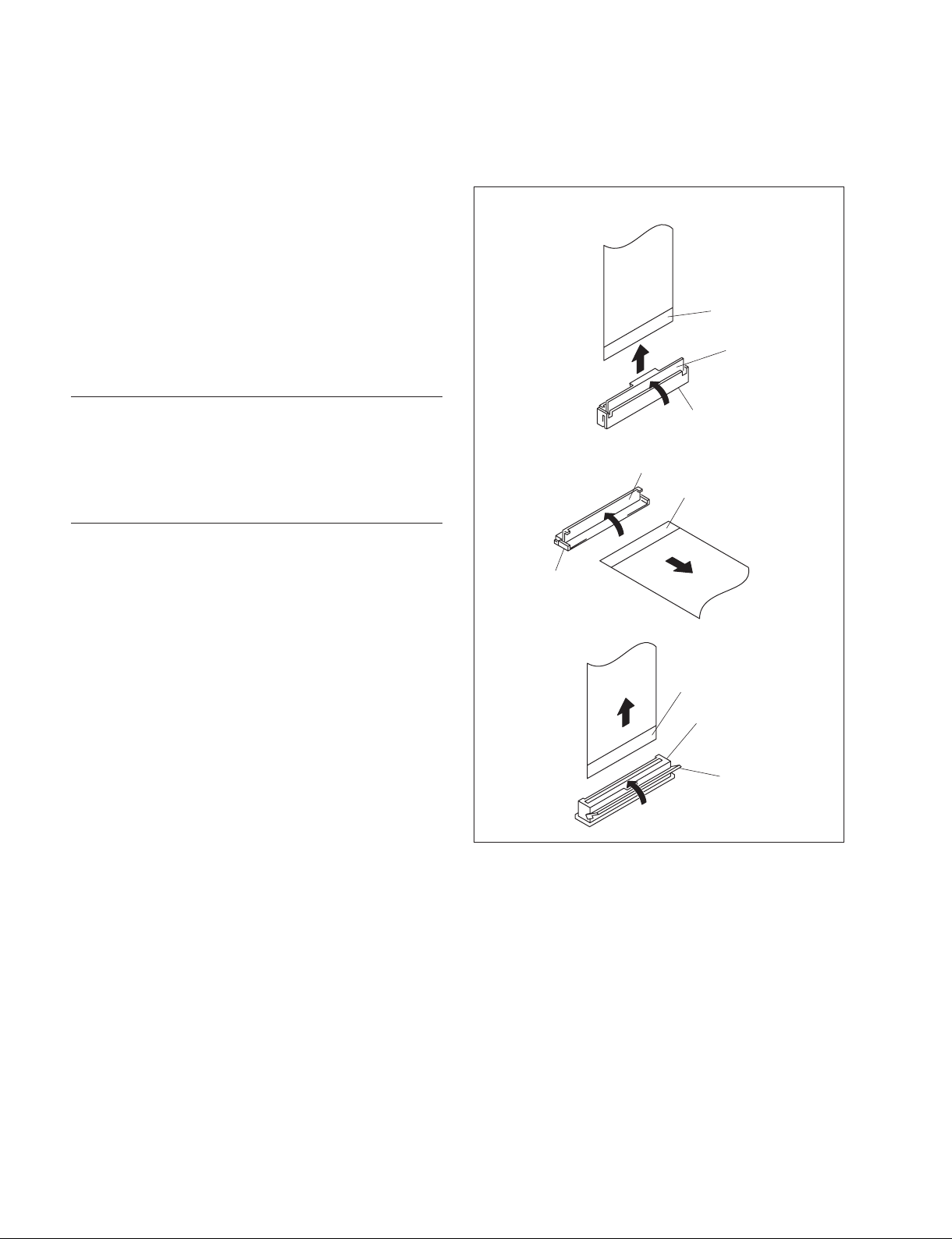
2-2. Connecting/Disconnecting the Flexible Card Wire
The fl exible card wires are used to connect between the
boards in this unit. Life of fl exible card wire will be signifi -
cantly shortened if it is bent. Be very careful not to bend
the fl exible card wire.
Three types of different-shaped connectors are used in this
unit. (Type A to type C)
Because the direction of the fl exible card wire is different
depending on the shape of the connector, be careful when
connecting the fl exible card wire.
Typ e A
Isolation surface
(blue)
A
Disconnecting
1. Turn off the power.
2. Raise the portion A in the direction of the arrow to
unlock and pull out the fl exible card wire.
Connecting
m
. Do not insert the fl exible card wire sideways.
. Confi rm that there is no stain or dust on the contact
surface of the fl exible card wire.
. When connecting the fl exible card wire, check the con-
nector shape, and great care should be taken for the
direction of the contact surface or isolation surface
(blue).
(Refer to illustration of the type A to type C.)
1. Raise the portion A in the direction of the arrow and
securely insert the fl exible card wire into the deep end
of the connector.
2. Return the portion A to its original position and lock
the connector.
Type B
Type C
Connector
A
Isolation surface (blue)
Connector
Isolation surface (blue)
Connector
A
2-2 (E)
HXCU-100

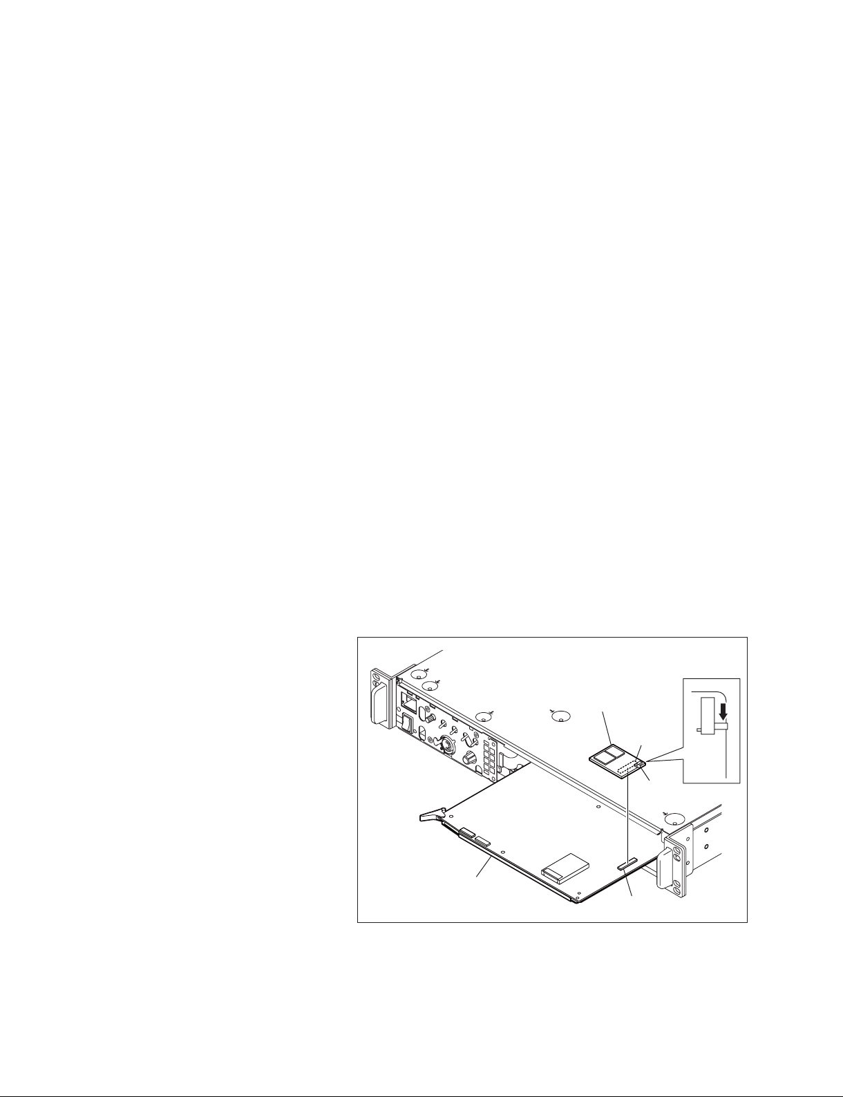
2-3. Upgrading the Software Programs
The ROM (IC812 and IC813 on the SY-364 board) version can be upgraded using a Memory Stick.
For upgrading the software programs, follow the procedures below.
2-3-1. Upgrading the Main Program
Tool
Memory Stick
Check
Check the current main program version with “ROM Version” of status display. (Refer to the Operating
Instructions.)
Preparation
Copy the upgrading program to the Memory Stick in the following steps.
n
To get the upgrading program (program fi les “hscu300.rom” and “boot.rom”), contact your local Sony
Sales Offi ce/Service Center.
(1) Make the following directory on the Memory Stick.
\MSSONY\PRO\CAMERA\HSCU300
(2) Copy the program fi les “hscu300.rom” and “boot.rom” to the directory made in step (1).
Procedure
1. Remove the front panel. (Refer to Section 5-1.)
2. Set the switch S801-2 on the SY-364 board to ON.
3. Insert the Memory Stick that contains the upgrading program into the connector CN804 on the
SY-364 board.
4. Turn on the power.
The diode D808 on the SY-364 board blinks green and red during upgrade, and lights green upon
completion of the upgrade.
5. Turn off the power and re-set S801-2 on the SY-364 board to OFF.
6. Remove the Memory Stick.
7. Attach the front panel.
8. When the unit is turned on, the main program is upgraded and runs.
9. Check that the main program has been upgraded with “ROM Version” of status display. (Refer to the
Operating Instructions.)
HXCU-100
2-3 (E)
2-3-2. Upgrading the Boot Program
Tools
. Memory Stick
. ROM-28 board: (Sony Part No.: A-8326-017-A)
Check
Check the current boot program version with FIRMWARE UPDATE of the MAINTENANCE menu.
(Refer to Section 4-3.)
Preparation
1. Copy the upgrading program to the Memory Stick in the following steps.
n
To get the upgrading program (program fi les “hscu300.rom” and “boot.rom”), contact your local Sony
Sales Offi ce/Service Center.
(1) Make the following directory on the Memory Stick.
\MSSONY\PRO\CAMERA\HSCU300
(2) Copy the program fi les “hscu300.rom” and “boot.rom” to the directory made in step (1).
2. Save the upgrading boot program in the ROMs H (IC2) and L (IC3) on the ROM-28 board.
n
For details of saving the upgrading program, contact your local Sony Sales Offi ce/Service Center.
Procedure
1. Remove the front panel.
(Refer to Section 5-1.)
2. Draw the SY-364 board.
(Refer to Section 5-5-13.)
3. Insert the Memory Stick that contains the
upgrading program into the connector CN804
on the SY-364 board.
4. Connect the connector CN1 on the ROM-28
board to the connector CN805 on the SY-364
board.
5. Set the switch S1 on the ROM-28 board to
the DOWNLOAD side.
6. Insert the SY-364 board and turn on the power.
The diode D808 on the SY-364 board blinks
green and red during upgrade, and lights
green upon completion of the upgrade.
7. Turn off the power, and remove the ROM-28
board from the SY-364 board.
8. Remove the Memory Stick.
9. Insert the SY-364 board, and attach the front
panel.
10. When the unit is turned on, the boot program
is upgraded and runs.
11. Check that the boot program has been upgraded with FIRMWARE UPDATE of the MAINTENANCE menu. (Refer to Section 4-3.)
SY-364 board
ROM-28 board
CN1
CN805
S1
LOAD
DOWN
2-4 (E)
HXCU-100
 Loading...