

Sony HKCU1001, HKCU1003, HKCU1005, HDCU3300 Installation Manual

HD CAMERA CONTROL UNIT
HDCU3300
SD ENCODER UNIT
HKCU1001
MULTI INTERFACE UNIT
HKCU1003
SDI OUTPUT EXPANSION UNIT
HKCU1005
INSTALLATION MANUAL
1st Edition
Serial No. 10001 and Higher : HDCU3300 (UC)
Serial No. 30001 and Higher : HDCU3300 (J)
Serial No. 40001 and Higher : HDCU3300 (CE)

! WARNING
This manual is intended for qualified service personnel only.
To reduce the risk of electric shock, fire or injury, do not perform any servicing other than that
contained in the operating instructions unless you are qualified to do so. Refer all servicing to
qualified service personnel.
! WARNUNG
Die Anleitung ist nur für qualifiziertes Fachpersonal bestimmt.
Alle Wartungsarbeiten dürfen nur von qualifiziertem Fachpersonal ausgeführt werden. Um die
Gefahr eines elektrischen Schlages, Feuergefahr und Verletzungen zu vermeiden, sind bei
Wartungsarbeiten strikt die Angaben in der Anleitung zu befolgen. Andere als die angegeben
Wartungsarbeiten dürfen nur von Personen ausgeführt werden, die eine spezielle Befähigung
dazu besitzen.
! AVERTISSEMENT
Ce manual est destiné uniquement aux personnes compétentes en charge de l’entretien. Afin
de réduire les risques de décharge électrique, d’incendie ou de blessure n’effectuer que les
réparations indiquées dans le mode d’emploi à moins d’être qualifié pour en effectuer d’autres.
Pour toute réparation faire appel à une personne compétente uniquement.
Attention-when the product is installed in Rack:
1. Prevention against overloading of branch circuit
When this product is installed in a rack and is
supplied power from an outlet on the rack, please
make sure that the rack does not overload the
supply circuit.
2. Providing protective earth
When this product is installed in a rack and is
supplied power from an outlet on the rack, please
confirm that the outlet is provided with a suitable
protective earth connection.
3. Internal air ambient temperature of the rack
When this product is installed in a rack, please make
sure that the internal air ambient temperature of the
rack is within the specified limit of this product.
4. Prevention against achieving hazardous
condition due to uneven mechanical loading
When this product is installed in a rack, please make
sure that the rack does not achieve hazardous
condition due to uneven mechanical loading.
5. Install the equipment while taking the operating
temperature of the equipment into consideration
For the operating temperature of the equipment,
refer to the specifications of the Operation Manual.
HDCU3300/IM (J,E)

Table of Contents
Manual Structure
Purpose of this manual ........................................................... 3 (E)
Related manuals .....................................................................3 (E)
Trademarks ............................................................................. 3 (E)
1. Installation Overview
1-1. Checking the ROM and Software Version .............. 1-1 (E)
1-2. Connectors and Cables ............................................ 1-2 (E)
1-2-1. Connector Input/Output Signal ...................... 1-2 (E)
1-2-2. Cable Wiring Diagram ................................... 1-6 (E)
1-2-3. Connection Connectors .................................. 1-7 (E)
1-2-4. Note when Connecting CAMERA
Connector ....................................................... 1-7 (E)
1-3. Circuit Boards and Main Parts Layouts ................... 1-8 (E)
1-4. External Dimensions ................................................ 1-9 (E)
1-5. Removing/Installing the Front Panel ....................... 1-9 (E)
1-6. On-board Indicator/Switch/Volume Functions ...... 1-10 (E)
1-7. Notes on Using the Power Supply Unit ................. 1-23 (E)
1-7-1. Setting the Power Voltage ............................ 1-23 (E)
1-7-2. Replacing the Fuse ....................................... 1-24 (E)
1-8. Installation Position of the Option Board .............. 1-25 (E)
1-9. Installing the Option Boards .................................. 1-26 (E)
1-10. Installing in 19-inch Rack ...................................... 1-27 (E)
1-11. Cleaning of Connector/Cable ................................ 1-30 (E)
2-5. Video Signal System .............................................. 2-12 (E)
2-5-1. Selecting the Input/Output Signal ................ 2-12 (E)
2-5-2. Adjusting the Signal Phase ........................... 2-12 (E)
2-5-3. Setting Aspect Ratio Conversion during
Down-convert ............................................... 2-13 (E)
2-5-4. Adjusting the Level of the VBS Signal
(only when HKCU1001/1003 is installed) ... 2-15 (E)
2-5-5. Adjusting the Level of Signals for
Waveform Monitor ....................................... 2-15 (E)
2-5-6. Adjusting the Level of Signals for
Picture Monitor ............................................ 2-18 (E)
2-5-7. Setting the RET Input ................................... 2-18 (E)
3. Menu Settings
3-1. Menu Operation ....................................................... 3-1 (E)
3-2. Status Display .......................................................... 3-2 (E)
3-3. System Menu ........................................................... 3-6 (E)
3-4. Configuration Menu ............................................... 3-10 (E)
2. System Setup
2-1. System Connection .................................................. 2-1 (E)
2-2. Setting the System Format ....................................... 2-6 (E)
2-2-1. Setting the Multi-Format ................................ 2-6 (E)
2-2-2. Setting the Reference Input ............................ 2-6 (E)
2-3. Audio System ........................................................... 2-7 (E)
2-3-1. Setting the Intercom System .......................... 2-7 (E)
2-3-2. Setting the Microphone .................................. 2-9 (E)
2-4. Systems .................................................................. 2-10 (E)
2-4-1. Setting the Tally System .............................. 2-10 (E)
2-4-2. Setting the Camera Number ......................... 2-10 (E)
2-4-3. Connecting the Control, Intercom,
Tally and Audio Signals ............................... 2-11 (E)
HDCU3300/IM (J,E)
1 (E)


Purpose of this manual
Related manuals
Manual Structure
This manual is the installation manual of the following models :
HD Camera Control Unit HDCU3300
SD Encoder Unit HKCU1001
Multi Interface Unit HKCU1003
SDI Output Expansion Unit HKCU1005
This manual is intended for use by trained system and service engineers, and
describes the information regarding the installation of the unit and the information
that premises the service based on components replacement.
Beside this Installation Manual, the following manuals are available for the unit.
. Operation Manual (Supplied with HDCU3300)
This manual describes how to operate the HDCU3300.
. Maintenance Manual (Available on request)
This manual intended for use by trained system and service engineers describes
(service overview and the circuit overview, the main part replacements, electrical
alignment, parts list, semiconductor pin assignments, block diagrams, schematic
diagrams, board layouts.) required for parts-level service.
For obtaining, contact your local Sony Sales Office/Service Center.
Part number : 9-968-308-0X
Trademarks
. “Semiconductor Pin Assignments” CD-ROM (Available on request)
This “Semiconductor Pin Assignments” CD-ROM allows you to search for
semiconductors used in Broadcast and Professional equipment.
This manual contains a complete list of semiconductors and their ID Nos., and
thus should be used together with the CD-ROM.
Part number: 9-968-546-0X
Trademarks and registered trademarks used in this manual are follows.
. Clear-Com is a registered trademark of Clear-Com Intercom Systems.
. Accuride is a registered trademark of Accuride International Corporation.
HDCU3300/IM (J, E)
3 (E)


Section 1
Installation Overview
1-1. Checking the ROM and Software Version
When connecting the following peripheral equipment to the unit, confirm the versions of the ROMs and
software which are installed in each model. If the version is lower than the following one, the ROM
needs to be replaced and the software needs to be upgraded.
In this case, contact your local Sony Sales Office/Service Center.
ROM
Peripheral equipment Board Ref. No. ROM version
MSU-700A/750 CPU-293/CPU-286 IC5, IC6/IC5, IC6 Ver.1.30 or higher
CNU-700 AT-89 or AT-89A IC4, IC5 Ver.3.20 or higher
CNU-500 AT-100 IC4, IC5 Ver.2.80 or higher
RCP-720/721 MPU-79 IC10 Ver.2.90 or higher
RCP-730/731 MPU-79 IC10 Ver.2.90 or higher
RCP-740/741 MPU-79 IC10 Ver.2.90 or higher
RCP-700/701 MPU-92 IC6 Ver.2.90 or higher
Software
Peripheral equipment Board Software version
MSU-900/950 CPU-396 Ver.1.02 or higher
RCP-750/751 MPU-123 Ver.1.21 or higher
RM-B750 MPU-124 Ver.1.00 or higher
HDC3300 AT-163S Ver.1.00 or higher
HDCU3300/IM (J,E)
1-1 (E)

1-2. Connectors and Cables
1-2-1. Connector Input/Output Signal
BNC connector
SS-A OUTPUT (1-2) : BNC
HD-SDI : SMPTE 292M 0.8 V p-p
75 Z, 1.485 Gbps/1.4835 Gbps
SS-B OUTPUT (1-2) : BNC
HD-SDI : SMPTE 292M 0.8 V p-p
75 Z, 1.485 Gbps/1.4835 Gbps
SS-C OUTPUT (1-2) : BNC
HD-SDI : SMPTE 292M 0.8 V p-p
75 Z, 1.485 Gbps/1.4835 Gbps
HD-SDI OUTPUT (1-4) : BNC
HD-SDI : SMPTE 292M 0.8 V p-p
75 Z, 1.485 Gbps/1.4835 Gbps
SDI OUTPUT (1-4) : BNC
Conforms to BTA-S004B, 0.8 V p-p, 75 Z, 1.485 Gbps/
1.4835 Gbps
SMPTE 292M
or
Component serial signal : 0.8 V p-p, 75 Z, 270 Mbps
SMPTE 259M
RETURN INPUT
..
. HD SDI (1-4) : BNC
..
Conforms to BTA-S004B, 1.485 Gbps/1.4835 Gbps
SMPTE 292M
..
. SD SDI (1-4) : BNC
..
Component serial signal : 270 Mbps
SMPTE 259M
..
. VBS (1-4) : BNC
..
Analog composite signal : 1.0 V p-p, 75 Z
INPUT
..
. REFERENCE : BNC
..
± 0.3 V, ternary SYNC, 75 Z
or 0.286 V p-p, black burst signal, 75 Z
..
. PROMPTER (1-2) : BNC
..
1.0 V p-p, 75 Z
OUTPUT
..
. SYNC : BNC
..
± 0.3 V, ternary SYNC, 75 Z
0.3 V p-p, SD SYNC, 75 Z selectable
..
. CHARACTER : BNC
..
1.0 V p-p, 75 Z
..
. AES/EBU : BNC
..
AES/EBU format
HKCU1001/1003
VBS (1-2) OUT : BNC
1.0 V p-p, 75 Z
PIX OUT : BNC
1.0 V p-p, 75 Z
WF OUT : BNC
0.714 V p-p, 75 Z (NTSC)
ENC : 1.0 V p-p
HKCU1003
FRAME REF IN : BNC (Not used)
0.3 V p-p FRAME SYNC pulse, 75 Z
or
± 0.3 V, ternary SYNC, 75 Z
or 0.286 V p-p, black burst signal, 75 Z
FRAME REF OUT : BNC (Not used)
THROUGH OUT/0.3 V p-p FRAME SYNC pulse, 75 Z
VBS OUT : BNC
1.0V p-p, 75 Z
PIX OUT : BNC
1.0 V p-p, 75 Z
WF OUT : BNC
0.714 V p-p, 75 Z (NTSC)
0.7 V p-p, 75 Z (PAL)
ENC : 1.0 V p-p
R-Y/R OUT : BNC (Not used)
R-Y : 0.7 V p-p, 75 Z (NTSC, SETUP : ON, when
outputting 75% color bar)
0.525 V p-p, 75 Z (PAL, when outputting 75% color bar)
R : 0.7 V p-p, 75 Z
1-2 (E)
HDCU3300/IM (J.E)
Y/G OUT : BNC (Not used)
Y : 1.0 V p-p (Video : 0.714 V, synchronous 0.286 V,
NTSC), 75 Z
1.0 V p-p (Video : 0.7 V, synchronous 0.3 V, PAL), 75 Z
G : 0.7 V p-p, 75 Z
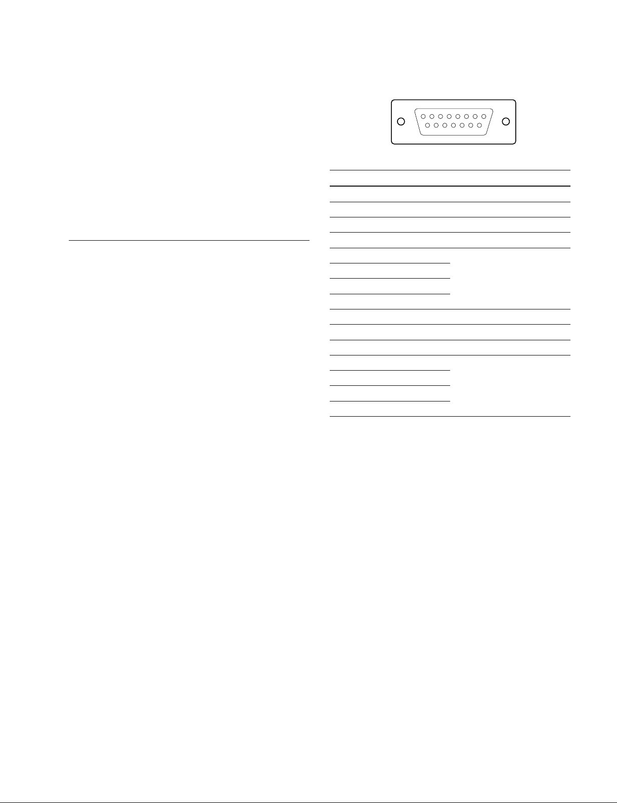
WF REMOTE (D-sub 15P, Female)
18
15 9
B-Y/B OUT : BNC (Not used)
B-Y : 0.7 V p-p, 75 Z (NTSC, SETUP : ON, when
outputting 75% color bar)
0.525 V p-p, 75 Z (PAL, when outputting 75% color bar)
B : 0.7 V p-p, 75 Z
HKCU1005
SDI OUT (1-4) : BNC
Conforms to BTA-S004B, 0.8 V p-p, 75 Z, 1.485 Gbps/
1.4835 Gbps
SMPTE 292M
or
Component serial signal : 0.8 V p-p, 75 Z, 270 Mbps
SMPTE 259M
CAMERA connector
(optical/electrical composite connector)
VIDEO RGB 4:4:4 3ch
10.692/10.681 Gbps serial
RET VIDEO Y/PB/P
R
10.692/10.681 Gbps serial
INCOM 2ch
MIC 2ch
DIGITAL AUDIO (AES/EBU)
CAMERA COMMAND
PROMPTER
__
_ EXT VIEW
__
No. Signal Specifications
1 NC No connection
2 NC No connection
3 NC No connection
4 NC No connection
5 RECALL2 (G) LOW ACTIVE
6 RECALL3 (B)
7 RECALL1 (R)
8 RECALL4 (SEQ)
9 GND
10 NC No connection
11 NC No connection
12 RECALL5 (ENC) LOW ACTIVE
13 RECALL6 (R+B)
14 RECALL7 (R+G)
15 RECALL8 (G+B)
__
_
__
HDCU3300/IM (J,E)
1-3 (E)
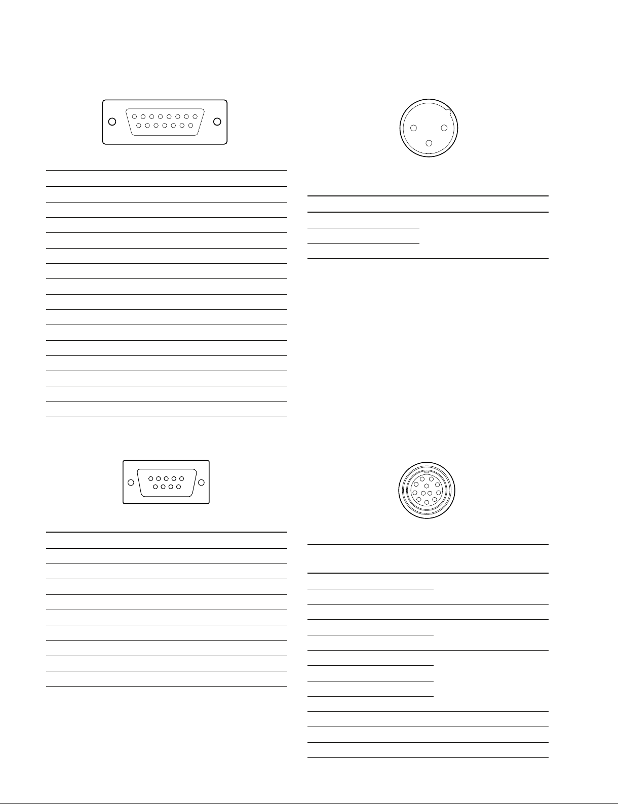
I/O PORT (D-sub 15P, Female)
MIC1/MIC2 (XLR 3P, Male)
18
15 9
__
_ EXT VIEW
__
__
_
__
No. Signal Specifications
1 IN1 GND/+5 V, OPEN (47 kZ +5 V PULL UP)
2 IN2 GND/+5 V, OPEN (47 kZ +5 V PULL UP)
3 IN3 GND/+5 V, OPEN (47 kZ +5 V PULL UP)
4 IN4 GND/+5 V, OPEN (47 kZ +5 V PULL UP)
5 IN5 GND/+5 V, OPEN (47 kZ +5 V PULL UP)
6 IN6 GND/+5 V, OPEN (47 kZ +5 V PULL UP)
7 IN7 GND/+5 V, OPEN (47 kZ +5 V PULL UP)
8 IN8 GND/+5 V, OPEN (47 kZ +5 V PULL UP)
9 GND
10 OUT1 0/+5 V (1 kZ)
11 OUT2 0/+5 V (1 kZ)
12 OUT3 0/+5 V (1 kZ)
13 OUT4 0/+5 V (1 kZ)
14 OUT5 0/+5 V (1 kZ)
15 OUT6 0/+5 V (1 kZ)
12
3
__
_ EXT VIEW
__
__
_
__
(0 dBu = 0.775 Vrms)
No. Signal Specifications
1 MIC OUT (G) 0 dBu/_20 dBu
2 MIC OUT (X) (Selectable with S500,
3 MIC OUT (Y) S501/AVP-6 board)
TRUNK LINE (D-sub 9P, Female)
5
9
__
_ EXT VIEW
__
No. Signal Specifications
1 NC No connection
2 EXT-CMD0-IN (RXD IN)
3 EXT-CHD0-OUT (TXD OUT)
4 NC No connection
5 GND
6 NC No connection
7 EXT-CMD1-OUT (RTS OUT)
8 EXT-CHD1-IN (CTS IN)
9 NC No connection
1
6
__
_
__
TRUNK A (12P, Female)
A
J
B
H
K
C
G
L M
D
F
E
__
_ EXT VIEW
__
No. Signal Specifications
RS422A RS232C
A TX1 (_) _ TRUNK Data out
B TX1 (+) _
C NC NC No connection
D TX0 (+) TX1 TRUNK Data out
E TX0 (_) TX0
F RX0 (_) RX0 TRUNK Data in
G RX0 (+) RX1
H RX1 (+) _
J RX1 (_) _
K GND GND GND for command
L NC NC No connection
M NC NC No connection
__
_
__
1-4 (E)
HDCU3300/IM (J.E)
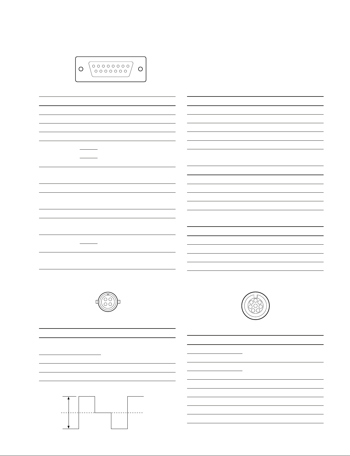
MIC REMOTE (D-sub 15P, Female)
15 9
18
__
_ EXT VIEW
__
__
_
__
No. Signal Specifications
1 +5.5 V OUT Max. 250 mA
2 TALLY GND GND for TALLY
3 G TALLY OUT ON (GND) : Max. 30 mA IN
4 R TALLY OUT ON (GND) : Max. 30 mA IN
5 CHU MIC CONT2 *1 Refer to the right column.
AMP
6
GAIN IN
7
CONT1
CONT0
8 MIC1 GAIN CONT *2 Refer to the right column.
ON/OFF IN
9 GND GND for +5.5 V
10 TALLY OUT R/G TALLY OUT
ON (GND) : Max. 30 mA IN
11 NC No connection
12 ASPECT REMOTE L : REMOTE
ON/OFF
13 ASPECT CONT1 *3 Refer to the right column.
CTL
14
CONT2
15 MIC2 GAIN CONT *2 Refer to the right column.
ON/OFF IN
*1 : CHU MIC 1/2 AMP GAIN
CONT0 CONT1 CONT2 CHU MIC AMP GAIN
H H H 60 dB
L H H 50 dB
H L H 40 dB
L L H 30 dB
H H L 20 dB
*2 :
8pin 15pin MIC GAIN CONT
L L MIC 1 and 2 ON
L H MIC 1 ON
H L MIC 2 ON
H H INTERNAL set
*3 :
CONT1 CONT2 ASPECT
L H SQ (16 : 9)
H H EC (4 : 3)
L L INTERNAL set
H L LB (4 : 3)
WF MODE (4P, Female)
4
1
3
2
__
_ EXT VIEW
__
No. Signal Specifications
1 SEQ CONT OUT (G) OPEN COLLECTOR
2 SEQ CONT OUT (X)
3 STAIR CASE OUT (X) *6
4 STAIR CASE OUT (G) GND for STAIR CASE
*6 : Stair Case signal
+1
12 V
_6
HDCU3300/IM (J,E)
RG B
__
_
__
+(PNP)/_(NPN)
(Selectable with S411/AT board)
DC 0 ±2 V
RCP/CNU (8P, Female)
1
2
7
8
6
3
5
4
__
_ EXT VIEW
__
No. Signal Specifications
1 TX (+) SERIAL DATA OUT
2 TX (_)
3 RX (+) SERIAL DATA IN
4 RX (_)
5 TX GND GND for TX
6 POWER (+) OUT +26 V, 200mA (max)
7 POWER (_) OUT GND for POWER
8 VIDEO (X) 75Z, 1.0 V p-p
CHASSIS GND CHASSIS GND
__
_
__
1-5 (E)
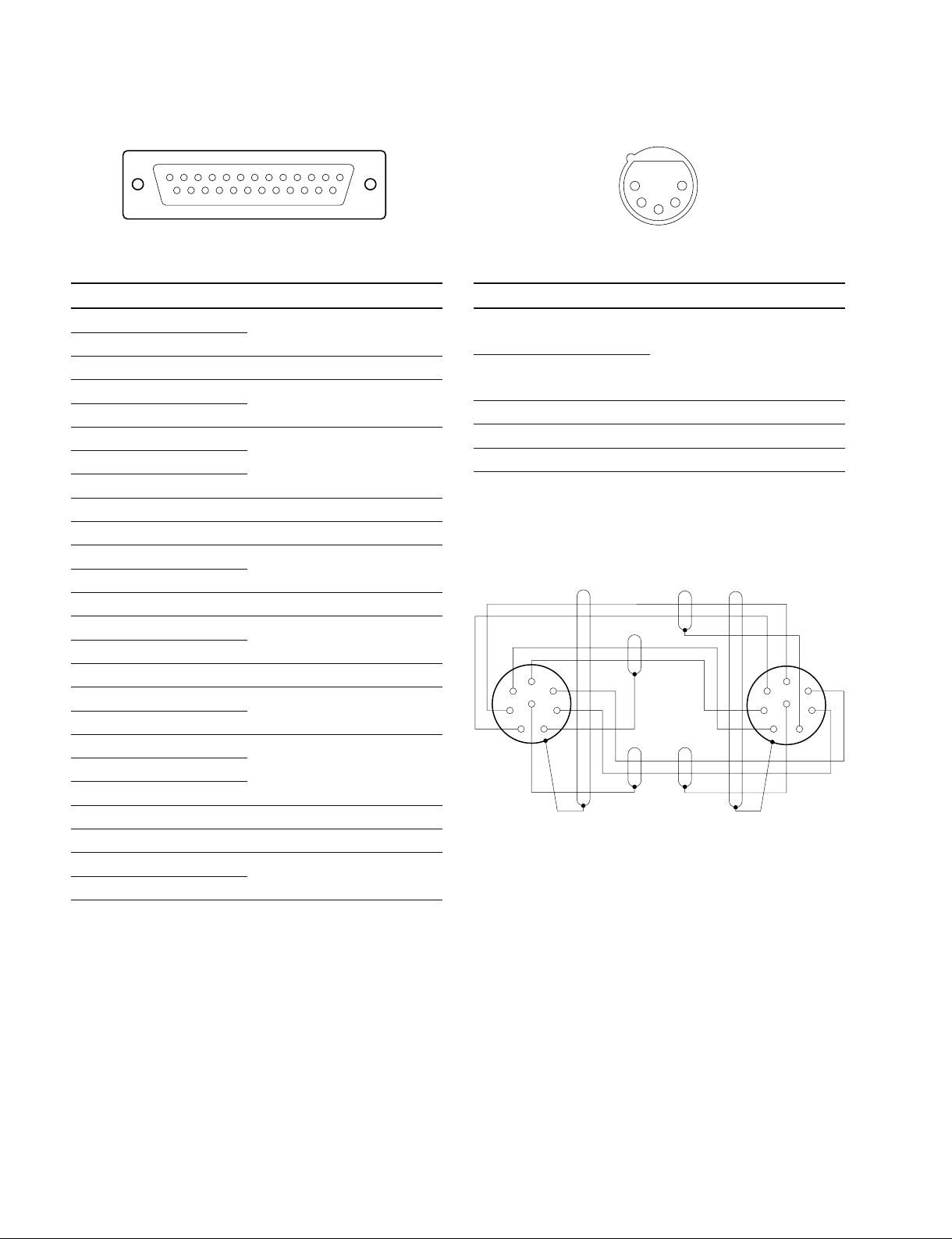
INTERCOM/TALLY/PGM (D-sub 25P, Female)
INTERCOM (5P, Female)
113
25 14
__
_ EXT VIEW
__
__
_
__
(0 dBu = 0.775 Vrms)
No. Signal Specifications
1 ENG (R) (X) OUT ENG SYSTEM RECEIVE
2 ENG (R) (Y) OUT 0 dBu BALANCED
3 ENG (G) GND for ENG
4 ENG (T) (X) IN ENG SYSTEM TALK
5 ENG (T) (Y) IN 0 dBu BALANCED
6 PGM1 (X) IN _20 dBu/0 dBu
7 PGM1 (Y) IN (Selectable with
8 PGM1 (G) IN S301/AT board)
9 GND GND for AUX
10 AUX3
11 R TALLY (X) IN ON : 24 Vdc, TTL (H), SHORT
12 R TALLY (Y) IN OFF : 0 Vdc, TTL (L), OPEN
13 GND CHASSIS GND
14 PROD (R) (X) OUT PROD SYSTEM
15 PROD (R) (Y) OUT RECEIVE 0 dBu BALANCED
16 PROD (G) GND for PROD
17 PROD (T) (X) IN PROD SYSTEM TALK
18 PROD (T) (Y) IN 0 dBu BALANCED
19 PGM2 (X) IN _20 dBu/0 dBu
20 PGM2 (Y) IN (Selectable with
21 PGM2 (G) IN S302/AT board)
22 AUX4
23 AUX5
24 G TALLY (X) IN ON : 24 Vdc, TTL (H), SHORT
25 G TALLY (Y) IN OFF : 0 Vdc, TTL (L), OPEN
5
__
_ EXT VIEW
__
1
2
4
3
__
_
__
(0 dBu = 0.775 Vrms)
No. Signal Specifications
1 INCOM (T) IN (Y) _20 dBu
(CARBON MIC)
2 INCOM (T) IN (X) _60 dBu
(DYNAMIC MIC)
3 INCOM (T) IN (G) GND for INCOM
4 INCOM (R) OUT (X) Max. 12 dBu
5 NC No connection
1-2-2. Cable Wiring Diagram
CCA-5 cable (RCP/CNU connector)
Black
White
Orange
White
Brown
1
7
2
3
485
6
Red
White
Red
Brown Brown
_ 8P CONNECTOR (MALE) _
(WIRING SIDE)
2
3
1
485
7
6
1-6 (E)
HDCU3300/IM (J.E)

1-2-3. Connection Connectors
When connecting cables to each connector of the connector panel during installation or service, connect the following connectors or equivalent to the tip.
Connector Connector/cable
HDCU3300
CAMERA . LEMO®
PUW. 3K. 93C. TLCC96 *1
(HDC3300 side)
CCU . LEMO®
FUW. 3K. 93C. TLMC96 *1
HDCU3300 1-564-742-11 PLUG, BNC or
VBS (1-4) B-B Cable assembly
PROMPTER (1-2) (1.5 m, optional)
REFERENCE
SYNC
CHARACTER
AES/EBU
HDCU3300 1-569-370-12 PLUG, BNC or
SS-A (1-2) BELDEN8281 Cable or
SS-B (1-2) equivalent
SS-C (1-2)
HD-SDI (1-4)
SLOT2 (1-4)
HD SDI (1-4)
SD SDI (1-4)
Connector Connector/cable
HKCU1005
SDI OUT (1-4)
MIC 1/2 1-508-083-00 XLR 3P Female
(3P, Male) or CANNON XLR-3-11C
equivalent
WF REMOTE/MIC REMOTE 1-506-582-11 D-sub 15P, Male
I/O PORT or JAE DA-CI-J10 equivalent
(D-sub 15P, Female)
INTERCOM/TALLY/PGM D-sub 25P, Male
(D-sub 25P, Female) JAE DA-25PF-N equivalent
WF MODE 1-560-155-00 PLUG, 4P Male
(4P, Female) (supplied with HKCU1001/1003)
RCP/CNU 1-766-848-11 PLUG, 8P Male
(8P, Female)
INCOM 1-508-370-11 XLR 5P, Male
(5P, Female) or CANNON XLR-5-12C
TRUNK LINE 1-560-651-00 D-sub 9P, Male
(D-sub 9P, Female) or JAE DE-9PF-N equivalent
*1 : Caution in making the optical/electric signal composite cable:
When making the optical/electric signal composite cable used for this
camera system, the connection connectors specified in this manual
must be used in order to comply with the limits for EMC regulations.
or CCA cable assembly (optional)
CCA-5-10 (10 m), CCA-5-3 (3 m)
equivalent
1-561-749-00 JUNCTION SHELL
1-2-4. Note when Connecting CAMERA
Connector
HKCU1001/1003
VBS (1-2)
PIX OUT
WF OUT
HKCU1003
FRAME REF IN (Not used)
FRAME REF OUT (Not used)
VBS
PIX OUT
WF OUT
R-Y/R (Not used)
Y/G (Not used)
B-Y/B (Not used)
(BNC)
HDCU3300/IM (J,E)
Before connecting the unit to the camera adaptor, clean the
following optical contact blocks.
For the cleaning procedure, refer to Section 1-11, “Cleaning of Connector/Cable”.
. CAMERA connector of the unit
. CCU connector of the camera side
. Optical/electric signal composite cable
1-7 (E)
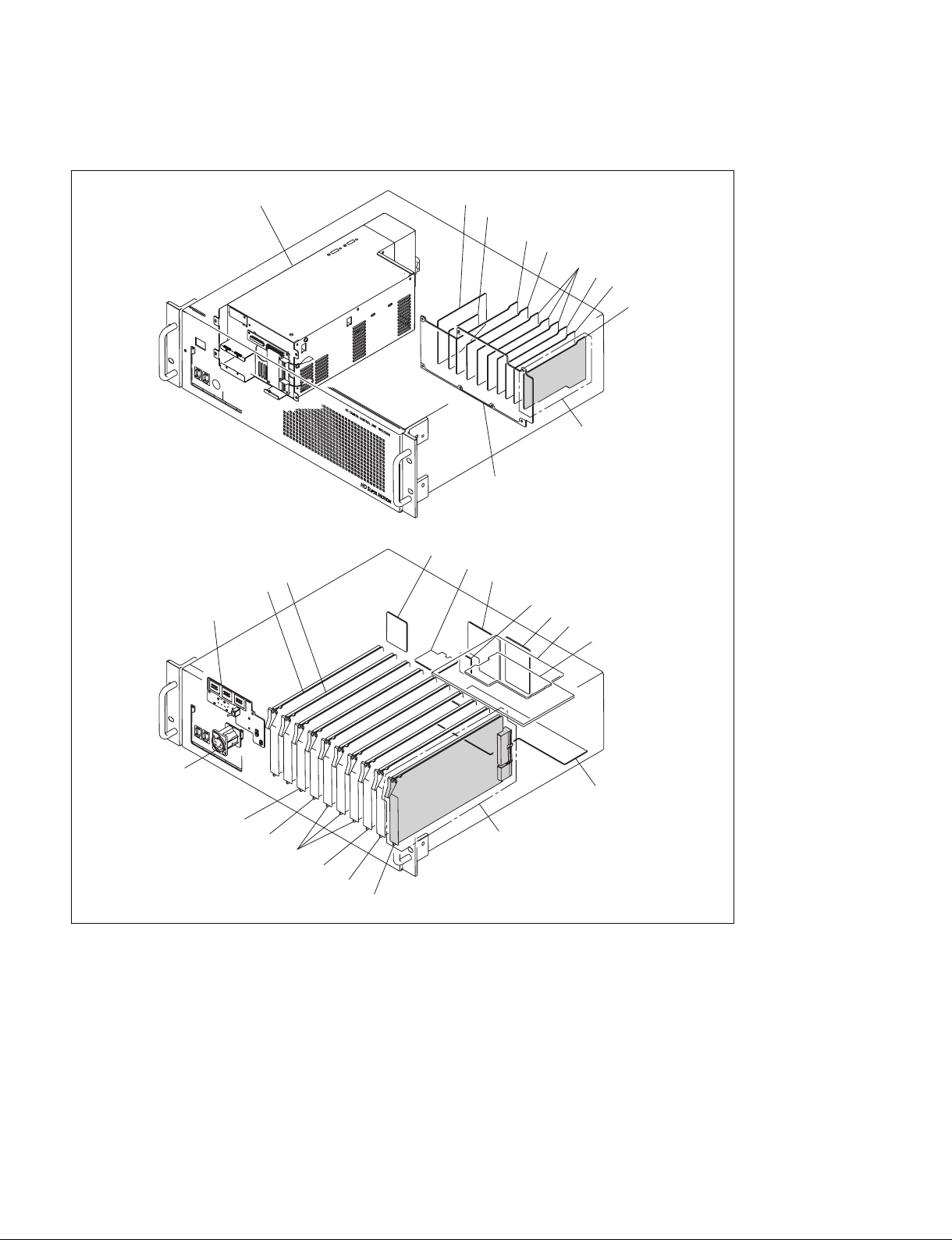
1-3. Circuit Boards and Main Parts Layouts
Power Supply Unit
9
8
7
!-
1
!=
2
6
![
3
!]
4
!'
5
Option
!\
@]
@;
@'
@-
!.
1 VIF-34G board
2 ADO-10G board
3 SDI-86G board
4 SDI-85 board
5 HIF-27 board
6 MB-1073 board
7 AU-302 board
8 AT-167S board
9 AVP-6 board
1-8 (E)
@=
0
!,
@[
@\
!/ DTX-5 board
!- CN-2718 board
!= CN-2673 board
![ CN-2672G board
!] CN-2805G board
!\ SDP-15 board
!; CBN-21G board
!' CN-2674G board
!, DRX-271A board
Option
@/
!. CN-2700 board
@/ EN-159A board (HKCU1001)
EN-159B board (HKCU1003)
DRX-5 board (HKCU1005)
@- VDA-64A board (HKCU1001)
VDA-64A board (HKCU1003)
VDA-64B board (HKCU1003)
HIF-26 board (HKCU1005)
@= CPU-395 board
!;
@[ DPR-271B board
@] OTR-1 board
@\ DRX-5 board
@; HIF-25 board
@' HIF-26 board
HDCU3300/IM (J.E)
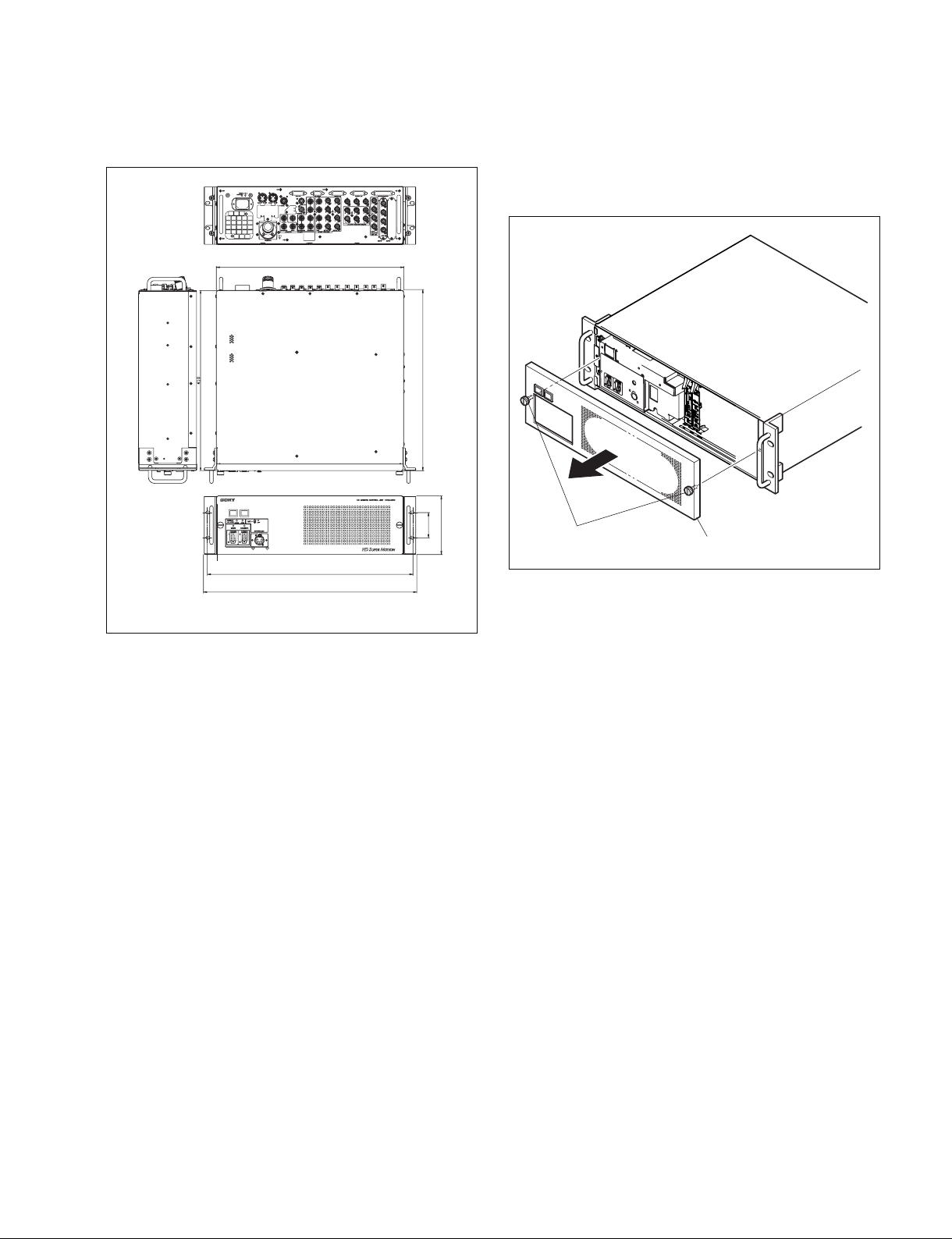
Front panel
Screws with stopper
1-4. External Dimensions
424
465
482
410
1-5. Removing/Installing the Front Panel
1. Fully loosen the two screws with stopper and remove
the front panel in the direction of the arrow.
57
132
2. Reattach the front panel in reverse order of step 1.
HDCU3300/IM (J,E)
1-9 (E)
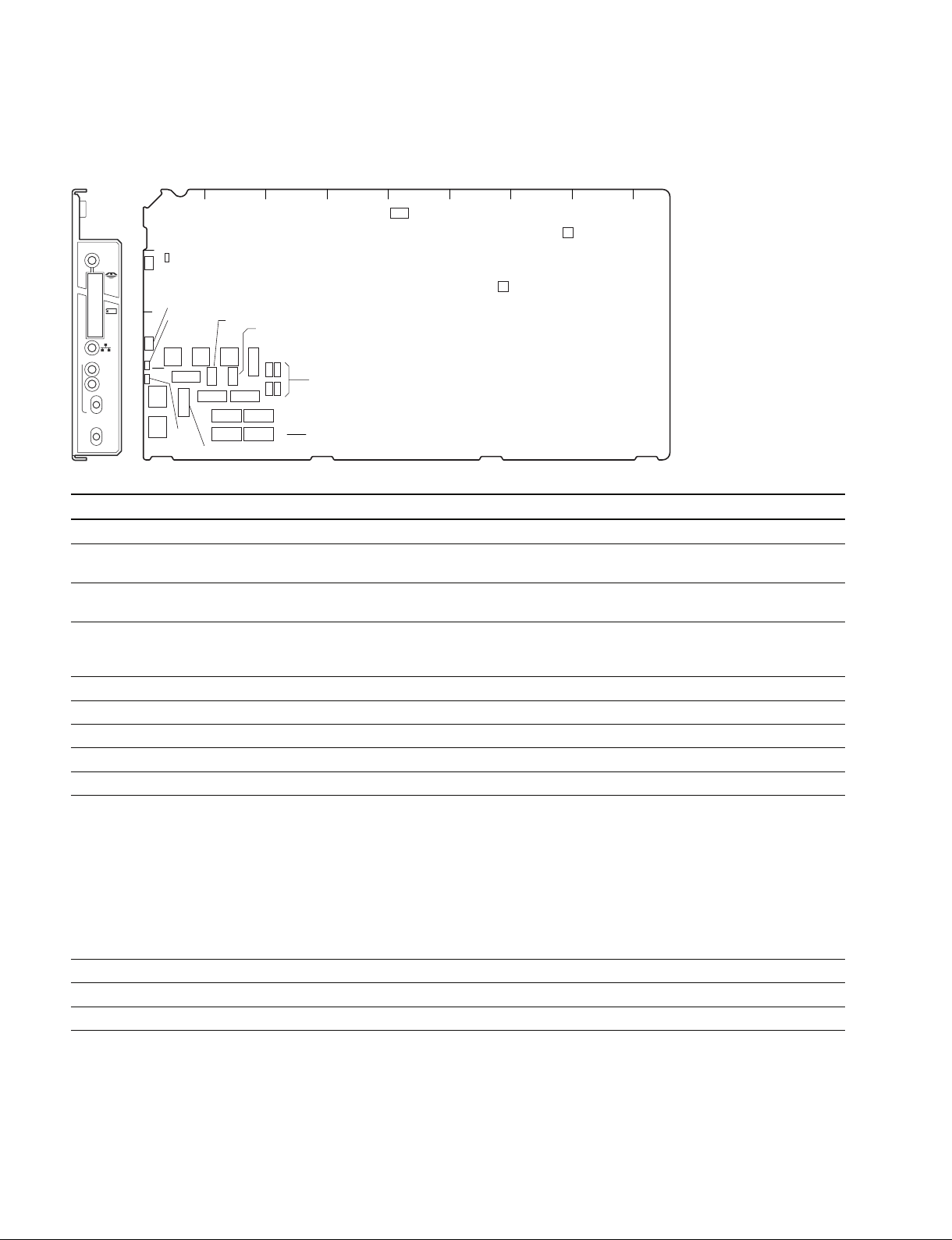
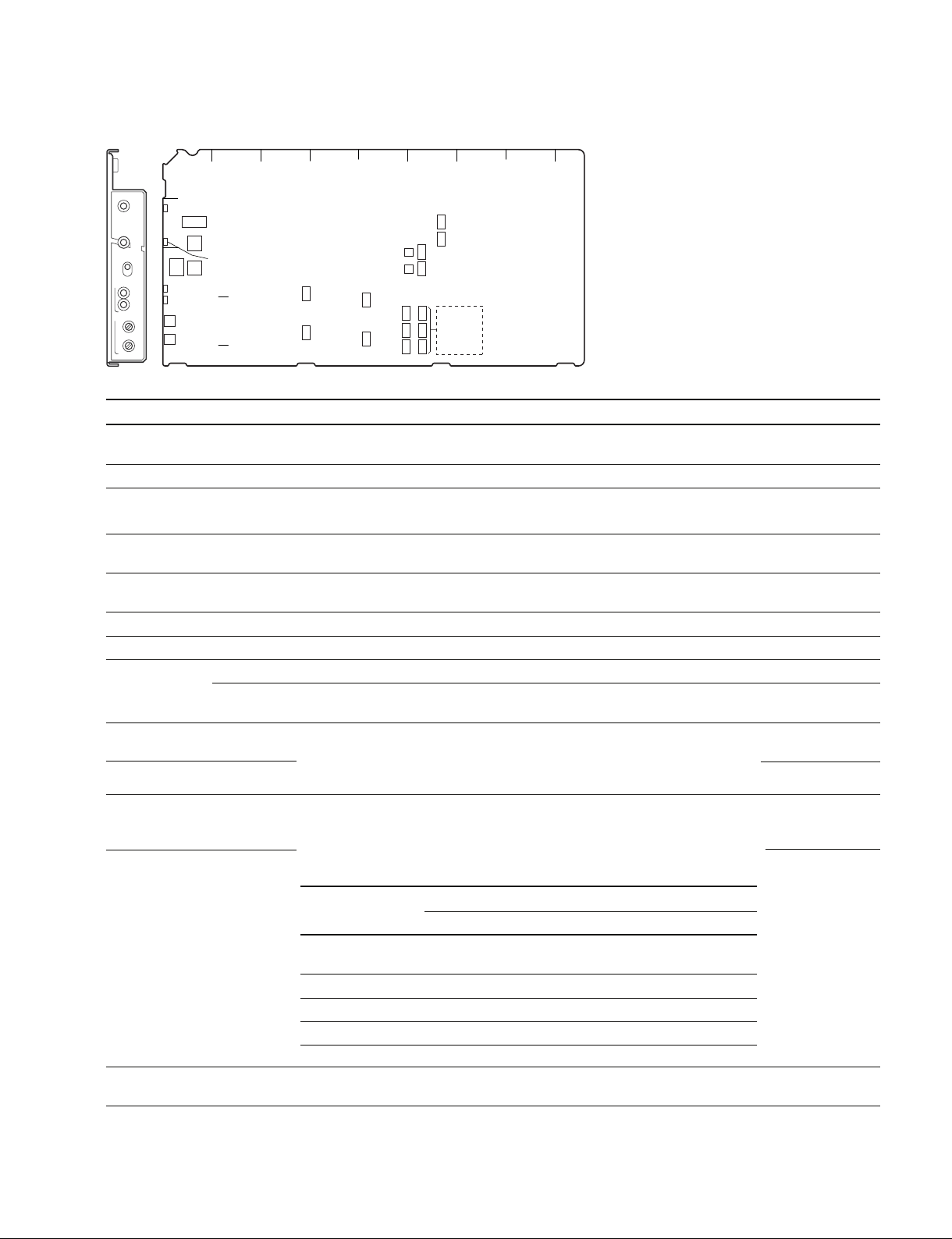
1-6. On-board Indicator/Switch/Volume Functions
AT-167S board
AB C D E F G HJ
S411
RV701
AT
REFERENCE
REF IN
UN
LOCK
HD
RMT
SD
H PHASE
ADV
DELAY
1
D4
D411
2
D412
D409
3
S403 S404 S405
S416
S401
D410
S402
S419
S420
S409
S408
S413
S418
S407
S406
S412
S410
S103
S104
S101
S102
4
5
RV702
AT-167S (Side A)
Ref.No. Name Function
Factory default setting
D4 POWER (Green) Illuminates when the power inside the AT board starts up correctly. _
D409 REF IN (Green) Illuminates when the reference signal is input and the external _
synchronous mode is established.
D410 UNLOCK (Red) Illuminates when CCU cannot lock the external reference signal in the _
external synchronous mode.
D411 MS-LED (Red/green) Displays the access status to the Memory Stick. _
Red light: Accessing the Memory Stick. Do not remove the Memory Stick.
Green light: The inserted Memory Stick can be removed.
D412 LAN-LED (Red/green) Not in operation. _
S101 PRTCT Factory use ON
S102 DEBUG Factory use OFF
S103 URA Factory use OFF
S104 DEBUG Factory use OFF
S401 REFERENCE Select the type of the synchronous signal to be connected to the REFERENCE REMOTE
terminal of this unit with this switch.
HD : Synchronizes (SYNC) with the HD reference signal.
(Input frame frequency is automatically adjusted.)
REMOTE : Controls from the remote panel such as that on MSU.
SD : Synchronizes (SYNC) with the SD reference signal (BB).
The VBS OUT signal synchronizes (SC) when HKCU1001/1003 is installed.
When the setting of the switch and the type of the input synchronous signal does
not match, the LED of D410 (UNLOCK) illuminates.
S402 H-PHASE Adjusts the H-phase.
S403 H-Phase (STEP) Adjusts the level phase for the reference signal in steps. 8
S404 V-Phase Adjusts the vertical phase for the reference signal in line steps. 8
1-10 (E)
HDCU3300/IM (J.E)

Ref.No. Name Function
S405 V-DLY Video phase setting between HD and SD 0
Sets the phase difference (delay time) between the HD signal and the SD
signal output from CCU.
The phase can be advanced as follows based on the delay time set with S410.
HD standard: 128ck (27 MHz) increment
SD standard: 256ck (74 MHz) increment
Factory default setting
S406 MODE1
1 MIC-GT 1&2/1,2 Sets whether controlling MIC1 and MIC2 independently or by interlocking them. OFF
2 MIC-G7 STD/700 For switching the interface specification of MIC-Remote (D-SUB-15P) OFF
3 D-SUB MIC/WFM Does not function
4
ASPECT RMT/PNL
5 Not used
6 CNU/RM Does not function
7 RCP-PX ENB/DIS Sets the monitor selection control method for PIX OUT by RCP. OFF
8
MONI-S M&R/RCP
S407 REFERENCE HD REFERENCE SD
Reference (advance amount Reference (advance amount
of SD) of HD)
00 0
1 _4.74 usec _3.45 usec
2 _9.48 usec _6.70 usec
3 _14.2 usec _10.3 usec
4 _19.0 usec _13.8 usec
5 _23.7 usec _17.2 usec
6 _28.4 usec _20.7 usec
7 _33.2 usec _24.1 usec
8 _37.9 usec _27.6 usec
9 _42.7 usec _31.0 usec
A _47.7 usec _34.5 usec
B _52.1 usec _37.9 usec
C _56.9 usec _41.4 usec
D _61.6 usec _44.8 usec
E _66.3 usec _48.3 usec
F _71.1 usec _51.7 usec
1H 525 : 63.5 usec 1125-60i : 29.6 usec 750-60P : 22.2 usec
625 : 64.0 usec 1125-50i : 35.6 usec 750-50P : 26.7 usec
1125-24 PsF : 37.0 usec
ON: MIC1, MIC2 independent control
OFF: MIC1, MIC2 interlocked control
ON: Old interface (700 mode)
OFF: Standard-I/F
ON: Accepts the switching command last input from MSU when the ASPECT OFF
switching from outside (D-Sub) is valid.
OFF: Does not accept the command input from MSU when the ASPECT
switching from outside (D-Sub) is valid.
ON : Only WF can be controlled from RCP.
OFF : Both PIX and WF can be controlled from RCP.
Sets the monitor selection control method for PIX/WF OUT. OFF
ON : Can only be controlled from RCP.
OFF : Can be controlled from either MSU or RCP. (Latest priority)
HDCU3300/IM (J,E)
1-11 (E)

Ref.No. Name Function
S407 TEST Factory use OFF
S408 MODE2
1 NP-SEL AUTO/N SD-Format setting OFF
ON: Forced into NTSC (525).
OFF: For AUTO, follows the setting of 1.000 (=PAL) /1.001 (=NTSC).
2 Not used
3 GRAY LINE/ON Gray signal output setting OFF
ON: During Gray signal output, when turning CB ON/OFF, the Gray image
disappears, leaving only the Line signal.
OFF: During Gray signal output, even when turning CB ON/OFF,
the Gray signal is output.
4 MONI/SYNC Does not function
5 Not used _
6 Not used _
7 Not used _
8 CO-AX DIS/ENB Factory use OFF
S409 CCU-NO CCU No. setting _
1 to 4 S409-4 to 1: 1’ digit (BCD) OFF (ALL)
5 to 8 S409-8 to 5: 10’ digit (BCD) OFF (ALL)
S410 HD-SD DLY Video phase setting between HD and SD LINE-DLY
Sets the phase difference (delay time) between HD signal and SD signal
output from CCU.
Can switch the delay settings among 0-DLY, LINE-DLY, and FRAME-DLY.
0-DLY : Same-phase mode of HD-SD (excluding 24PsF)
LINE-DLY : Sets the minimum delay amount of D/C. SD signal delays as
much as 90H (1080i) or 120H (720P).
FRAME-DLY : Sets the frame delay amount. SD signal delays as much as
1 frame (1080i) or 2 frames (720P).
* 90H is the level frequency of 1125-60i/50i, and 120H is that of 750-60P/50P.
S411 SEQ1&SEQ2 Switch depending on the waveform monitor to be used. (+)
+ : PNP : PNP open collector output
_ : NPN : NPN open collector output
Factory default setting
1-12 (E)
HDCU3300/IM (J.E)

Ref.No. Name Function
S412 SYNC Sets the SYNC signal output from the SYNC terminal to HD or SD. SD
HD : HD-SYNC signal output
SD : SD-SYNC signal output
S413 Factory use OFF
S416 Co-AX Not used (D-S-Fi) Fiber
S418 48V/50V/60V Multi-Format setting (Camera transmission format) 60
When the operation clock frequency setting switch (S420) is set to Local, the main
video format of CCU is set as in the following table. The output transmission format
of CHU is also set in the same way. (Refer to the table below.)
S419 720/Psf/I Multi-Format setting (Camera transmission format) INTR
When the operation clock frequency setting switch (S420) is set to Local, the main
video format of CCU is set as in the following table. The output transmission format
of CHU is set in the same way. (Refer to the table below.)
FORMAT S420 S418 S419
1080-60 (or 59.94) i 1.000 (or 1.001) 60 V Intr
1080-30 (or 29.97) PsF 1.000 (or 1.001) 60 V PsF
1080-50 i 1.000 50 V Intr
1080-25 PsF 1.000 50 V PsF
1080-24 (or 23.98) PsF 1.000 (or 1.001) 48 V PsF
720-60 (or 59.94) P 1.000 (or 1.001) 60 V 720 P
720-50 P 1.000 50 V 720 P
Factory default setting
S420 1001/REMOTE/1000 Operation clock frequency setting REMOTE
1.001 : Sets the field frequency of CCU to 59.94, 29.97, 23.98 Hz.
1.000 : Sets the field frequency of CCU to 60, 50, 25, 24 Hz.
REMOTE : Can be set from MSU.
* Can also perform remote/local setting of video output format from CCU.
RV701 27M FREQ Volume that adjusts the free-run frequency of 27M-VCO (X701). Must be
RV702 CK-DUTY Volume that adjusts the clock duty of the 74 MHz clock.
readjusted when replacing X701.
HDCU3300/IM (J,E)
1-13 (E)
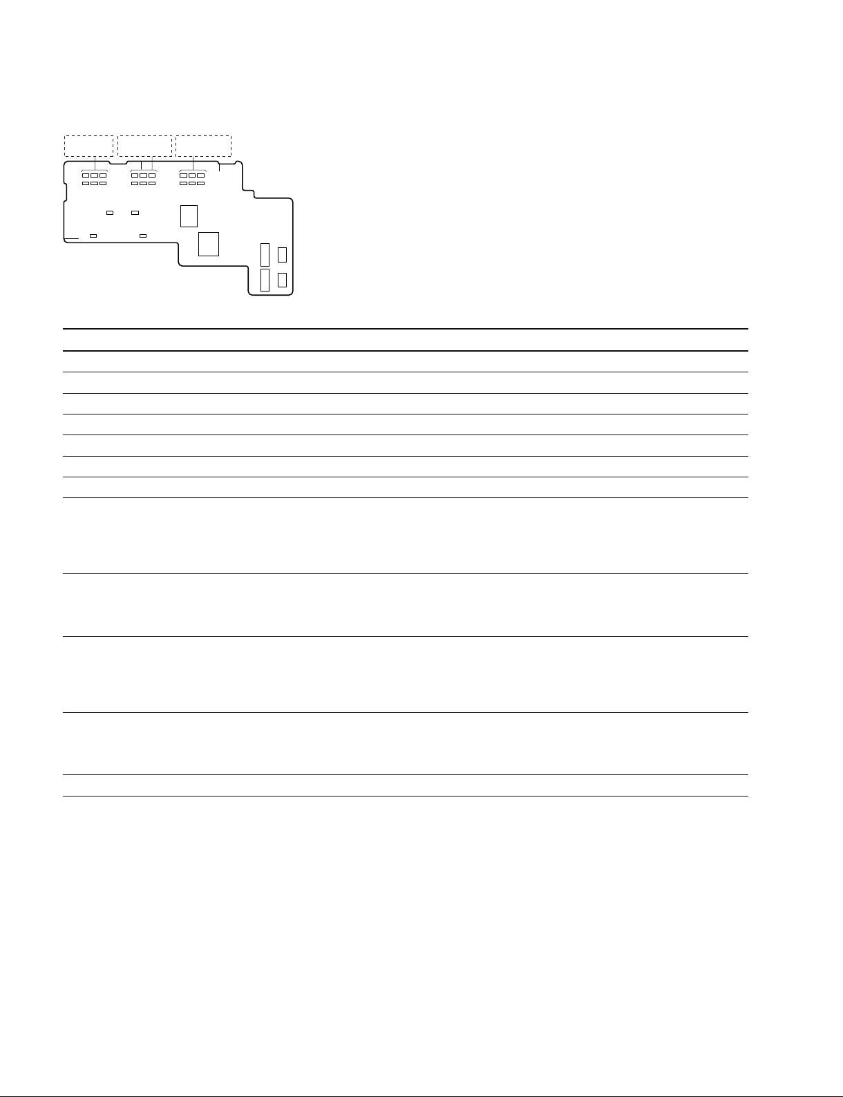
AU-302 board
D5 D7 D9
D6 D8 D10
1
D11 D13 D15
D12 D14 D16
AB C
D4 D3
D2D1
D17 D19 D21
D18 D20 D22
S1
RV1
2
S2
S3
S5
S4
AU-302 (Side A)
Ref.No. Name Function
Factory default setting
D1 MAIN POWER Refer to the Operation Manual. _
D2 CAMERA POWER Refer to the Operation Manual. _
D3 CABLE ALARM OPEN Refer to the Operation Manual. _
D4 CABLE ALARM SHORT Refer to the Operation Manual. _
D5-D10 RED TALLY Refer to the Operation Manual. _
D11-D16 GREEN TALLY Refer to the Operation Manual. _
S1 MIC Refer to the Operation Manual. _
S2 INCOM
Selects the line to which the INCOM connector on the front panel is connected.
PROD
PROD : Producer line
PRIV: Private (When the unit is disconnected from the producer line or engineer
line, only the intercom between the unit and the camera is possible.)
ENG : Engineer line
S3 INCOM-RECEIVE For switching between a voice and PGM for the front intercam reception. OFF
PGM-OFF: The FP-INCOM reception becomes a voice.
PGM-ON : The FP-INCOM reception becomes PGM.
* Switching of receipt is valid when the INCOM MIX switch is set to OFF.
S4 FRONT MIC
Sets the microphone input level according to the type of headset microphone to
CARBON
be connected to the INCOM connector on the front panel.
DYNAMIC : Dynamic microphone (_60 dB)
ECM : Electret condenser microphone (_40 dB)
CARBON : Carbon microphone (_20 dB)
- The power is not supplied.
- The power is supplied.
- The power is supplied.
S5 UNBALANCE Select ON/OFF according to the headset microphone type connected to the OFF
INCOM connector on the front panel.
ON: For the unbalanced type (UNBALANCE)
OFF: For the balanced type
RV1 INTERCOM Refer to the Operation Manual.
1-14 (E)
HDCU3300/IM (J.E)
AVP-6 board
1
AVP
CCU
POWER
D104
2
CAM
LOCK
CAM POWER
SYSTEM
2WIRE CANCEL
S1
ON/
OFF
D106
/1.001
D109
LINE
DELAY
RV600
PROD
RV601
ENG
AB C D E F G HJ
S500
S501
S12 S11
S22
S32
S502
S503
S21
S31
S4
S2
D105
S3
3
S602
RV500
RV501
S600
4
S603
S601
5
AVP-6 (Side A)
Ref.No. Name Function
Factory default setting
D104 CCU POWER (Green) Illuminates when the power to the boards in the whole CCU is _
functioning properly.
D105 CAM LOCK (Green) Illuminates when the communication with CHU is normal. _
D106 /1001 (Green) Illuminates when the operation clock frequency of SG is 74.17582 MHz. _
(When the frame frequency of the video signal is integer 1/1.001.)
D109 LINE DELAY (Yellow) Illuminates when the SD signal delay at down-conversion is set to _
LINE-DELAY-MODE (NTSC : 42H, PAL : 50H)
S1 CAM POWER Toggle switch that turns on the power to the camera head when it is off, and turns
off when it is on.
S2 Not used 0
S3 Not used 0
S4 MODE 1-7 Factory use OFF (ALL)
8 Set this to ON when upgrading the PLD (IC208, IC409) version of the SDP-15 OFF
board. (Be sure to set the switch to OFF after the upgrade is completed.)
S11 R-TALLY Set according to the signal standard of the R-TALLY signal input to the INTERCOM/ CONTACT
(POWER/CONTACT) TALLY/PGM connector on the rear panel. For the relationship between the signal
S12 R-TALLY and the switch setting, refer to the table below. TTL
(POWER/TTL)
S21 G-TALLY Set according to the signal standard of the G-TALLY signal input to the INTERCOM/ CONTACT
(POWER/CONTACT) TALLY/PGM connector on the rear panel. For the relationship between the signal
and the switch setting, refer to the table below.
S22 G-TALLY TTL
Tally system setting
(POWER/TTL)
Red tally Green tally
Switch S11 S12 S21 S22
Signal standard POWER/ POWER/TTL POWER/ POWER/TTL
CONTACT CONTACT
Contact supply CONTACT _ CONTACT _
24 V power supply POWER POWER POWER POWER
5 V power supply POWER TTL POWER TTL
S31 U-TALLY Not used CONTACT
(POWER/CONTACT)
HDCU3300/IM (J,E)
1-15 (E)

Ref.No. Name Function Factory default setting
S32 U-TALLY Not used TTL
(POWER/TTL)
Tally system setting
U tally
Switch S31 S32
Signal standard POWER/ POWER/TTL
CONTACT
Contact supply CONTACT _
24 V power supply POWER POWER
5 V power supply POWER TTL
S500 MIC1 LEV Sets the output level of MIC. 0 dB
S501 MIC2 LEV Sets the output level of MIC. 0 dB
S502 PGM1 IN Sets the input level of the system PGM (analog). 0 dB
S503 PGM2 IN Sets the input level of the system PGM (analog). 0 dB
S602 PROD SEL Selects the intercom system of the producer line. 4W
S600 PROD SEL2 RTS
S603 ENG SEL Selects the intercom system of the engineer line. 4W
S601 ENG SEL2 RTS
0dB : When the input level on the system is 0 dBu.
_20dB: When the input level on the system is _20 dBu.
0dB : When the input level on the system is 0 dBu.
_20dB: When the input level on the system is _20 dBu.
0dB : When the input level of the system is 0 dBu.
_20dB: When the input level of the system is _20 dBu.
0dB : When the input level of the system is 0 dBu.
_20dB: When the input level of the system is _20 dBu.
S602 S600
4-Wire 4W *
RTS RTS RTS
Clear-Com RTS CC
* When 4-Wire is selected, S600 can be set to RTS or CC.
S603 S601
4-Wire 4W *
RTS RTS RTS
Clear-Com RTS CC
* When 4-Wire is selected, S601 can be set to RTS or CC.
RV500 MIC1 LEV Adjusts the level of the signal output from the MIC1 connector on the rear panel.
RV501 MIC2 LEV Adjusts the level of the signal output from the MIC2 connector on the rear panel.
RV600 PROD 2WIRE CANCEL
RV601 ENG 2WIRE CANCEL
1-16 (E)
HDCU3300/IM (J.E)
 Loading...