

Page 1
983463735.pdf
HDR-CX190/CX190E/CX200/CX200E/CX210/CX210E/
SERVICE MANUAL
Ver. 1.4 2012.08
Revised-4
Replace the previously issued
SERVICE MANUAL 9-834-637-34
with this Manual.
Photo: HDR-PJ210/Silver
PJ200/PJ200E/PJ210
LEVEL 2
US Model
Canadian Model
AEP Model
UK Model
North European Model
E Model
Australian Model
Hong Kong Model
Chinese Model
Korea Model
Brazilian Model
Tourist Model
Japanese Model
Revision History
Ver. Date History Contents
1.0 2011.12 Official Release — —
1.1 2012.01 Revised-1
(A1 11-347)
1.2
1.3
1.4
2012.05 Revised-2
(A2 12-020)
2012.06 Revised-3
(A3 12-164)
2012.08 Revised-4
(A4 12-186)
• Change of SERVICE NOTE.
Page 1-2, 1-3, 1-4, 1-6, 1-7, 1-8, 1-9
• Change of EXPLODED VIEWS.
Page 2-3, 2-7, 2-9, 2-10
• Correction of ACCESSORIES.
Page 2-12, 2-13
• Change of REPAIR PARTS LIST.
Page 2-8
S.M. Rev.
issued
Ye s
Ye s
Ye s
Ye s
SERVICE NOTE (Check the following note before the service.)
– ENGLISH –
1-1. POWER SUPPLY DURING REPAIRS
1-2.
1-3. ADDITION OF DESTINATION DATA FILE
1-4. SELF-DIAGNOSIS FUNCTION
1-5. NOTE ON REPLACING PROJECTOR UNIT (HDR-PJ200/PJ200E/PJ210)
‒JAPANESE‒
1-1. 修理時の電源供給について
1-2.
1-3. DestinationDataファイルの追加について
1-4. 自己診断機能
1-5. プロジェクターユニット交換時の注意(HDR-PJ200/PJ200E/PJ210)
PRECAUTION ON REPLACING THE VC-651 BOARD
VC-651基板交換時の注意
Digital HD Video Camera Recorder
The components identified by mark
0 or dotted line with mark 0 are
critical for safety.
Replace only with part number
specified.
HDR-CX190/CX190E/CX200/CX200E/CX210/CX210E/PJ200/PJ200E/PJ210_L2
9-834-637-35
Les composants identifiés par une
marque 0 sont critiques pour la
sécurité.
Ne les remplacer que par une
pièce portant le numéro spécifié.
Sony Corporation
2012H08-1
© 2012.08
Published by Sony Techno Create Corporation
Page 2
These specifications are extracted from instruction manual of
HDR-CX190E/CX200E/CX210E/PJ200E.
– ENGLISH –
These specifications are extracted from instruction manual of
HDR-CX190/CX200/CX210/PJ200.
– ENGLISH –
System
Signal format: PAL color, CCIR standards
HDTV 1080/50i specification
Movie recording format:
HD: MPEG-4 AVC/H.264 AVCHD format
Ver.2.0 compatible
STD: MPEG2-PS
Audio recording system:
Dolby Digital 2ch
Dolby Digital Stereo Creator
Photo file format:
DCF Ver.2.0 Compatible
Exif Ver.2.3 Compatible
MPF Baseline Compatible
Recording media (Movie/Photo):
Internal memory
HDR-CX210E: 8 GB
“Memory Stick PRO Duo” media (Mark2)
SD card (Class 4 or faster)
The capacity that a user can use: Approx.
7.88 GB (HDR-CX210E)
1 GB equals 1 billion bytes, a portion of
which is used for system management
and/or application files. Only pre-installed
demonstration movie may be deleted.
Image device:
3.1 mm (1/5.8 type) CMOS sensor
Recording pixels (photo, 16:9):
Max. 5.3 mega (3 072 × 1 728) pixels
Gross: Approx. 1 500 000 pixels
Effective (movie, 16:9)
Approx. 1 310 000 pixels
Effective (photo, 16:9):
Approx. 1 330 000 pixels
Effective (photo, 4:3):
Approx. 1 000 000 pixels
Lens: Carl Zeiss Vario-Tessar Lens
25 × (Optical)
(Digital)
F1.8 ~ 3.2
Focal length:
f=2.5 mm ~ 62.5 mm (1/8 in. ~ 2 1/2 in.)
When converted to a 35 mm still camera
For movies
(1 7/16 in. ~ 42 5/8 in.) (16:9)
For photos: 36 mm ~ 900 mm
(1 7/16 in. ~ 35 1/2 in.) (16:9)
Color temperature: [Auto], [One Push], [Indoor]
(3 200 K), [Outdoor] (5 800 K)
Minimum illumination:
11 lx (lux) (in default setting, shutter speed
1/50 second)
3 lx (lux) ([Low Lux] is set to [On], shutter
speed 1/25 second)
*1
*2
*3
*3
The unique image processing system of
Sony’s BIONZ allows still image resollu-
tion equivalent to the sizes described.
[ SteadyShot] is set to [Active].
[ SteadyShot] is set to [Standard] or
[Off].
*3
:
*2
, 30 × (Extended)*3, 300 ×
: 36 mm ~ 1 080 mm
*1
SPECIFICATIONS
Input/Output connectors
A/V Remote Connector:
Video and audio output jack
HDMI OUT jack: HDMI mini connector
USB jack: mini-AB/Type A (Built-in USB)
(output only)
LCD screen
Picture: 6.7 cm (2.7 type, aspect ratio 16:9)
Total number of pixels: 230 400 (960 × 240)
Projector (HDR-PJ200E)
Projection type: DLP
Light source: LED (R/G/B)
Focus: Manual
Throw Distance: 0.5 m (1.6 feet) or over
Contrast ratio: 1500:1
Resolution (output): nHD (640 × 360)
Continuous projection time (when using the
supplied battery pack): Approx. 70 min
General
Power requirements: DC 6.8 V/7.2 V (battery
pack) DC 8.4 V (AC Adaptor)
USB Charging: DC 5 V 500 mA/1.5 A
Average power consumption:
During camera recording using LCD screen
at normal brightness:
HD: 2.1 W STD: 1.9 W
Operating temperature: 0 °C to 40 °C
(32 °F to 104 °F)
Storage temperature: –20 °C to +60 °C
(–4 °F to +140 °F)
Dimensions (approx.):
HDR-CX190E:
51 mm × 56 mm × 107.5 mm
(2 1/8 in. × 2 1/4 in. × 4 1/4 in.) (w/h/d)
including the projecting parts
51 mm × 56 mm × 114 mm
(2 1/8 in. × 2 1/4 in. × 4 1/2 in.) (w/h/d)
including the projecting parts, and the
supplied rechargeable battery pack attached
HDR-CX200E/HDR-CX210E:
51 mm × 56 mm × 106.5 mm
(2 1/8 in. × 2 1/4 in. × 4 1/4 in.) (w/h/d)
including the projecting parts
51 mm × 56 mm × 114 mm
(2 1/8 in. × 2 1/4 in. × 4 1/2 in.) (w/h/d)
including the projecting parts, and the
supplied rechargeable battery pack attached
HDR-PJ200E:
58 mm × 56 mm × 106.5 mm
(2 3/8 in. × 2 1/4 in. × 4 1/4 in.) (w/h/d)
including the projecting parts
58 mm × 56 mm × 114 mm
(2 3/8 in. × 2 1/4 in. × 4 1/2 in.) (w/h/d)
including the projecting parts, and the
supplied rechargeable battery pack attached
Mass (approx.)
HDR-CX190E:
168 g (5.9 oz) main unit only
210 g (7.4 oz) including the supplied
rechargeable battery pack
HDR-CX200E/HDR-CX210E:
175 g (6.2 oz) main unit only
217 g (7.7 oz) including the supplied
rechargeable battery pack
HDR-PJ200E:
210 g (7.4 oz) main unit only
252 g (8.9 oz) including the supplied
rechargeable battery pack
AC Adaptor AC-L200C/AC-L200D
Power requirements: AC 100 V - 240 V,
50 Hz/60 Hz
Current consumption: 0.35 A - 0.18 A
Power consumption: 18 W
Output voltage: DC 8.4 V*
Operating temperature: 0 °C to 40 °C
(32 °F to 104 °F)
Storage temperature: –20 °C to +60 °C
(–4 °F to +140 °F)
Dimensions (approx.):
48 mm × 29 mm × 81 mm
(1 15/16 in. × 1 3/16 in. × 3 1/4 in.)
(w/h/d) excluding the projecting parts
Mass (approx.): 170 g (6.0 oz) excluding the
power cord (mains lead)
* See the label on the AC Adaptor for other
specifications.
Rechargeable battery pack NP-FV30
Maximum output voltage: DC 8.4 V
Output voltage: DC 7.2 V
Maximum charge voltage: DC 8.4 V
Maximum charge current: 2.12 A
Capacity
Typical: 3.6 Wh (500 mAh)
Minimum: 3.6 Wh (500 mAh)
Type: Li-ion
Design and specifications of your camcorder and
accessories are subject to change without notice.
• Manufactured under license from Dolby Labo-
ratories.
System
Signal format: NTSC color, EIA standards
HDTV 1080/60i specification
Movie recording format:
HD: MPEG-4 AVC/H.264 AVCHD format
Ver.2.0 compatible
STD: MPEG2-PS
Audio recording system:
Dolby Digital 2ch
Dolby Digital Stereo Creator
Photo file format:
DCF Ver.2.0 Compatible
Exif Ver.2.3 Compatible
MPF Baseline Compatible
Recording media (Movie/Photo):
Internal memory
HDR-CX210: 8 GB
“Memory Stick PRO Duo” media (Mark2)
SD card (Class 4 or faster)
The capacity that a user can use: Approx.
7.88 GB (HDR-CX210)
1 GB equals 1 billion bytes, a portion of
which is used for system management
and/or application files. Only pre-installed
demonstration movie may be deleted.
Image device:
3.1 mm (1/5.8 type) CMOS sensor
Recording pixels (photo, 16:9):
Max. 5.3 mega (3 072 × 1 728) pixels
Gross: Approx. 1 500 000 pixels
Effective (movie, 16:9)
Approx. 1 310 000 pixels
Effective (photo, 16:9):
Approx. 1 330 000 pixels
Effective (photo, 4:3):
Approx. 1 000 000 pixels
Lens: Carl Zeiss Vario-Tessar Lens
25 × (Optical)
(Digital)
F1.8 ~ 3.2
Focal length:
f=2.5 mm ~ 62.5 mm (1/8 in. ~ 2 1/2 in.)
When converted to a 35 mm still camera
For movies
(1 7/16 in. ~ 42 5/8 in.) (16:9)
For photos: 36 mm ~ 900 mm
(1 7/16 in. ~ 35 1/2 in.) (16:9)
Color temperature: [Auto], [One Push], [Indoor]
(3 200 K), [Outdoor] (5 800 K)
Minimum illumination:
11 lx (lux) (in default setting, shutter speed
1/60 second)
3 lx (lux) ([Low Lux] is set to [On], shutter
speed 1/30 second)
*1
*2
*3
*3
The unique image processing system of
Sony’s BIONZ allows still image resollu-
tion equivalent to the sizes described.
[ SteadyShot] is set to [Active].
[ SteadyShot] is set to [Standard] or
[Off].
*3
:
*2
, 30 × (Extended)*3, 300 ×
: 36 mm ~ 1 080 mm
*1
SPECIFICATIONS
Input/Output connectors
A/V Remote Connector:
Video and audio output jack
HDMI OUT jack: HDMI mini connector
USB jack: mini-AB/Type A (Built-in USB)
LCD screen
Picture: 6.7 cm (2.7 type, aspect ratio 16:9)
Total number of pixels: 230 400 (960 × 240)
Projector (HDR-PJ200)
Projection type: DLP
Light source: LED (R/G/B)
Focus: Manual
Throw Distance: 0.5 m (1.6 feet) or over
Contrast ratio: 1500:1
Resolution (output): nHD (640 × 360)
Continuous projection time (when using the
supplied battery pack): Approx. 70 min
General
Power requirements: DC 6.8 V/7.2 V (battery
pack) DC 8.4 V (AC Adaptor)
USB Charging: DC 5 V 500 mA/1.5 A
Average power consumption:
During camera recording using LCD screen
at normal brightness:
HD: 2.1 W STD: 1.9 W
Operating temperature: 0 °C to 40 °C
(32 °F to 104 °F)
Storage temperature: –20 °C to +60 °C
(–4 °F to +140 °F)
Dimensions (approx.):
HDR-CX190:
51 mm × 56 mm × 107.5 mm
(2 1/8 in. × 2 1/4 in. × 4 1/4 in.) (w/h/d)
including the projecting parts
51 mm × 56 mm × 114 mm
(2 1/8 in. × 2 1/4 in. × 4 1/2 in.) (w/h/d)
including the projecting parts, and the
supplied rechargeable battery pack attached
HDR-CX200/HDR-CX210:
51 mm × 56 mm × 106.5 mm
(2 1/8 in. × 2 1/4 in. × 4 1/4 in.) (w/h/d)
including the projecting parts
51 mm × 56 mm × 114 mm
(2 1/8 in. × 2 1/4 in. × 4 1/2 in.) (w/h/d)
including the projecting parts, and the
supplied rechargeable battery pack attached
HDR-PJ200:
58 mm × 56 mm × 106.5 mm
(2 3/8 in. × 2 1/4 in. × 4 1/4 in.) (w/h/d)
including the projecting parts
58 mm × 56 mm × 114 mm
(2 3/8 in. × 2 1/4 in. × 4 1/2 in.) (w/h/d)
including the projecting parts, and the
supplied rechargeable battery pack attached
Mass (approx.)
HDR-CX190:
168 g (5.9 oz) main unit only
210 g (7.4 oz) including the supplied
rechargeable battery pack
HDR-CX200/HDR-CX210:
175 g (6.2 oz) main unit only
217 g (7.7 oz) including the supplied
rechargeable battery pack
HDR-PJ200:
210 g (7.4 oz) main unit only
252 g (8.9 oz) including the supplied
rechargeable battery pack
AC Adaptor AC-L200C/AC-L200D
Power requirements: AC 100 V - 240 V,
50 Hz/60 Hz
Current consumption: 0.35 A - 0.18 A
Power consumption: 18 W
Output voltage: DC 8.4 V*
Operating temperature: 0 °C to 40 °C
(32 °F to 104 °F)
Storage temperature: –20 °C to +60 °C
(–4 °F to +140 °F)
Dimensions (approx.):
48 mm × 29 mm × 81 mm
(1 15/16 in. × 1 3/16 in. × 3 1/4 in.)
(w/h/d) excluding the projecting parts
Mass (approx.): 170 g (6.0 oz) excluding the
power cord (mains lead)
* See the label on the AC Adaptor for other
specifications.
Rechargeable battery pack NP-FV30
Maximum output voltage: DC 8.4 V
Output voltage: DC 7.2 V
Maximum charge voltage: DC 8.4 V
Maximum charge current: 2.12 A
Capacity
Typical: 3.6 Wh (500 mAh)
Minimum: 3.6 Wh (500 mAh)
Type: Li-ion
Design and specifications of your camcorder and
accessories are subject to change without notice.
• Manufactured under license from Dolby Labo-
ratories.
HDR-CX190/CX190E/CX200/CX200E/CX210/CX210E/PJ200/PJ200E/PJ210_L2
– 2 –
Page 3
システム
信号方式
NTSCカラー、EIA標準方式
HDTV 1080/60i方式
ビデオ記録方式
HD画質:MPEG-4 AVC/H.264
規格 Ver.2.0 準拠
AVCHD
STD画質:MPEG-2 PS
音声記録方式
Dolby Digital 2ch
(ドルビーデジタルステレオクリエーター搭載)
静止画ファイルフォーマット
:DCF Ver2.0準拠
:
Exif Ver2.3準拠
:
MPF Baseline準拠
記録メディア(動画・静止画)
内蔵メモリー:
メモリースティック PRO デュオ
SDカード(Class4以上)
使用可能容量:約
容量は、1GBを10億バイトで計算した場合の数
値です。また管理用ファイル、アプリケーショ
ンファイルなどを含むため、実際に使用できる
容量は減少します。内蔵デモンストレーション
動画は削除が可能です。
撮像素子:
3.1 mm(1/5.8型)CMOSセンサー
記録画素数:静止画時
(3 072 × 1 728)(16:9時)
総画素数:約
動画時有効画素数
静止画時有効画素数(
静止画時有効画素数(
ズームレンズ:カールツァイス バリオテッサー
25倍(光学)
300倍(デジタル)
F1.8 〜 3.2
f=2.5
35mm
動画撮影時
36 〜 1 080 mm(16:9)
静止画撮影時:
36 〜 900 mm(16:9)
色温度切り換え:[オート]、[ワンプッシュ]、[屋内]
(
3 200 K)、[屋外](5 800 K)
最低被写体照度:
11 lx(ルクス)(お買い上げ時、[シャッタース
ピード]
3 lx(ルクス)([ Low Lux]が[入]時、[シャッ
タースピード]
*1
ソニー独自の画像処理システムBIONZによ
り、静止画は表記の記録サイズを実現して
います。
*2
[ 手ブレ補正]が[アクティブ]のとき
*3
[ 手ブレ補正]が[スタンダード]、または[切]
のとき
8 GB
7.88 GB
最大530万画素相当
150万画素
*3
( 16:9):約131万画素
16:9):約133万画素
4:3):約100万画素
*2
、30倍(エクステンデッド)*3、
〜 62.5 mm
カメラ換算では
*3
:
1/60秒)
1/30秒)
*1
概略仕様
入/出力端子
HDMI OUT端子:HDMIミニコネクタ
USB端子:mini-AB/タイプA(ビルトインUSB)
液晶モニター
画面サイズ:6.7 cm(2.7型、アスペクト比16:9)
総ドット数:
プロジェクター
表示方式:DLP
光源:LED(R/G/B)
フォーカス:マニュアル
投写距離(約):最低
コントラスト比:
解像度(出力):nHD(640 × 360)
連続投影可能時間(付属バッテリー使用時):約
電源部、その他
電源電圧:バッテリー端子入力 6.8 V/7.2 V
消費電力:明るさ標準:
動作温度:0 ℃〜 40 ℃
保存温度:−
外形寸法:
本体質量:
撮影時総質量:
230 400ドット
横
960×縦240
0.5 m以上
1500:1
端子入力 8.4 V
DC
充電:DC 5 V 500 mA/1.5 A
USB
HD:2.1 W STD:1.9 W
20 ℃〜 +60 ℃
58 mm × 56 mm × 106.5 mm
(突起部を含む)(幅×高さ×奥行き)
58 mm × 56 mm × 114.5 mm
(突起部を含む、付属バッテリー装着状態)
(幅×高さ×奥行き)
約
210 g (本体のみ)
約
252 g (付属バッテリー含む)
70分
– JAPANESE –
ACアダプター
AC-L200C/AC-L200D
電源:AC 100 V - 240 V、50 Hz/60 Hz
消費電流:0.35 A - 0.18 A
消費電力:18 W
定格出力:DC 8.4 V
動作温度:0 ℃〜 40 ℃
保存温度:−
外形寸法:約
(幅×高さ×奥行き)
質量:約
*
その他の仕様についてはACアダプターのラベルを
ご覧ください。
リチャージャブルバッテリーパック
NP-FV30
最大電圧:DC 8.4 V
公称電圧:DC 7.2 V
最大充電電圧:DC 8.4 V
最大充電電流:2.1 A
容量:
公称容量:
定格(最小)容量:
使用電池:
本機やアクセサリーの仕様および外観は、改良
のため予告なく変更することがありますが、
ご了承ください。
•
ドルビーラボラトリーズからの実施権に基づ
き製造されています。
*
20 ℃〜 +60 ℃
48×29×81 mm(最大突起部を除く)
170 g(本体のみ)
3.6 Wh(500 mAh)
3.6 Wh(500 mAh)
Li-ion
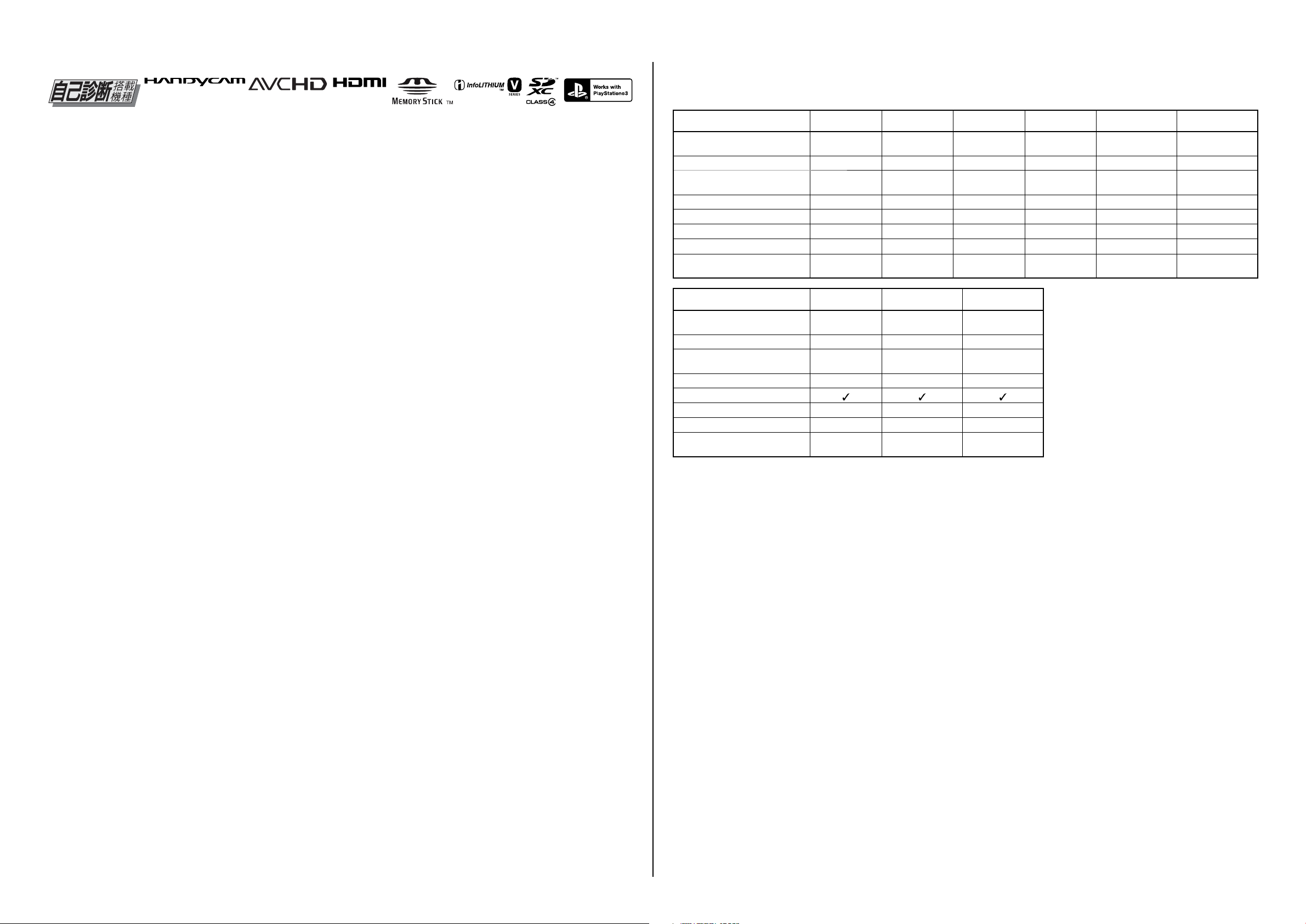
Model information table
Model HDR-CX190 HDR-CX190E HDR-CX200 HDR-CX200E HDR-CX210 HDR-CX210E
Destination
US, CND, E,
KR, BR
AEP, UK, NE,
E, AUS
US, CND, E,
KR
AEP, NE, E US, CND, E
AEP, UK, NE, E,
HK, CH
COLOR system NTSC PAL NTSC PAL NTSC PAL
Recording media
‑‑‑‑
Internal memory
8 GB
Internal memory
8 GB
LENS LSV-1181A LSV-1181A LSV-1181A LSV-1181A LSV-1181A LSV-1181A
Projector
GPS
Hot shoe
Charging capacitor
(for flash)
‑‑‑‑ ‑ ‑
‑‑‑‑ ‑ ‑
‑‑‑‑ ‑ ‑
‑‑‑‑ ‑ ‑
Model HDR-PJ200 HDR-PJ200E HDR-PJ210
Destination
US, CND, E,
KR, BR, JE
AEP, UK, NE, E,
AUS, CH, JE
CND, J
COLOR system NTSC PAL NTSC
Recording media
‑‑
Internal memory
8 GB
LENS LSV-1181A LSV-1181A LSV-1181A
Projector
GPS
Hot shoe
Charging capacitor
(for flash)
‑‑ ‑
‑‑ ‑
‑‑ ‑
MODEL GROUP
Projector Model: HDR-PJ200/PJ200E/PJ210
Non Projector Model: HDR-CX190/CX190E/CX200/CX200E/CX210/CX210E
IM Model (Internal Memory Model): HDR-CX210/CX210E/PJ210
Non IM Model (Non Internal Memory Model): HDR-CX190/CX190E/CX200/CX200E/PJ200/PJ200E
• Abbreviation
AUS: Australian model
BR: Brazilian Model
CH: Chinese model
CND: Canadian model
HK: Hong Kong model
J: Japanese model
JE: Tourist model
KR: Korea model
NE: North European model
HDR-CX190/CX190E/CX200/CX200E/CX210/CX210E/PJ200/PJ200E/PJ210_L2
– 3 –
Page 4
– ENGLISH – – JAPANESE –
Danger of explosion if battery is incorrectly replaced.
Caution
Replace only with the same or equivalent type.
Dispose of used batteries according to the instructions.
SAFETY-RELATED COMPONENT WARNING!!
COMPONENTS IDENTIFIED BY MARK 0 OR DOTTED LINE WITH
MARK 0 ON THE SCHEMA TIC DIAGRAMS AND IN THE P ARTS LIST
ARE CRITICAL TO SAFE OPERATION. REPLACE THESE COMPONENTS WITH SONY PARTS WHOSE PART NUMBERS APPEAR AS
SHOWN IN THIS MANUAL OR IN SUPPLEMENTS PUBLISHED BY
SONY.
SAFETY CHECK-OUT
After correcting the original service problem, perform the following
safety checks before releasing the set to the customer.
1. Check the area of your repair for unsoldered or poorly-soldered
connections. Check the entire board surface for solder splashes and
bridges.
2. Check the interboard wiring to ensure that no wires are “pinched”
or contact high-wattage resistors.
3. Look for unauthorized replacement parts, particularly transistors,
that were installed during a previous repair. Point them out to the
customer and recommend their replacement.
4. Look for parts which, through functioning, show obvious signs of
deterioration. Point them out to the customer and recommend their
replacement.
5. Check the B+ voltage to see it is at the values specified.
6. Flexible Circuit Board Repairing
• Set the soldering iron tip temperature to 350 °C approximately.
• Do not touch the soldering iron on the same conductor of the circuit
board (within 3 times).
• Be careful not to apply force on the conductor when soldering or
unsoldering.
ATTENTION AU COMPOSANT AYANT RAPPORT
À LA SÉCURITÉ!
LES COMPOSANTS IDENTIFIÉS PAR UNE MARQUE 0 SUR LES
DIAGRAMMES SCHÉMATIQUES ET LA LISTE DES PIÈCES SONT
CRITIQUES POUR LA SÉCURITÉ DE FONCTIONNEMENT. NE REMPLACER CES COMPOSANTS QUE PAR DES PIÈCES SONY DONT
LES NUMÉROS SONT DONNÉS DANS CE MANUEL OU DANS LES
SUPPLÉMENTS PUBLIÉS PAR SONY.
UNLEADED SOLDER
This unit uses unleaded solder.
Boards requiring use of unleaded solder are printed with the lead free
mark (LF) indicating the solder contains no lead.
(Caution: Some printed circuit boards may not come printed with the
lead free mark due to their particular size.)
: LEAD FREE MARK
Be careful to the following points to solder or unsolder.
• Set the soldering iron tip temperature to 350 °C approximately.
If cannot control temperature, solder/unsolder at high temperature
for a short time.
Caution: The printed pattern (copper foil) may peel away if the
heated tip is applied for too long, so be careful!
Unleaded solder is more viscous (sticky, less prone to
flow) than ordinary solder so use caution not to let solder
bridges occur such as on IC pins, etc.
• Be sure to control soldering iron tips used for unleaded solder and
those for leaded solder so they are managed separately. Mixing unleaded solder and leaded solder will cause detachment phenomenon.
電池の交換は,正しく行わないと破裂する恐れがあります。
注意
電池を交換する場合には必ず同じ型名の電池又は同等品と
交換してください。
使用済み電池は,取扱指示に従って処分してください。
サービス,点検時には次のことにご注意ください。
1. 注意事項をお守りください。
サービスのとき特に注意を要する個所については,キャビ
ネット,シャーシ,部品などにラベルや捺印で注意事項を
表示しています。これらの注意書き及び取扱説明書等の注
意事項を必ずお守り下さい。
2. 指定部品のご使用を
セットの部品は難燃性や耐電圧など安全上の特性を持った
ものとなっています。従って交換部品は,使用されていた
ものと同じ特性の部品を使用して下さい。特に回路図,部
品表に0印で指定されている安全上重要な部品は必ず指定
のものをご使用下さい。
3. 部品の取付けや配線の引きまわしはもとどおりに
安全上,チューブやテープなどの絶縁材料を使用したり,
プリント基板から浮かして取付けた部品があります。また
内部配線は引きまわしやクランパによって発熱部品や高圧
部品に接近しないよう配慮されていますので,これらは必
ずもとどおりにして下さい。
4. サービス後は安全点検を
サービスのために取外したネジ,部品,配線がもとどおり
になっているか,またサービスした個所の周辺を劣化させ
てしまったところがないかなどを点検し,安全性が確保さ
れていることを確認して下さい。
5. チップ部品交換時の注意
・ 取外した部品は再使用しないで下さい。
・ タンタルコンデンサのマイナス側は熱に弱いため交換時
は注意して下さい。
6. フレキシブルプリント基板の取扱いについて
・ 半田こてのこて先温度は約350℃に設定してください。
・ 同一パターンに何度もコテ先を当てないで下さい。(3回
以内)
・ パターンに力が加わらないよう注意して下さい。
無鉛半田について
本機には無鉛半田が使用されています。
無鉛半田を使用している基板には,無鉛(LeadFree)を意味する
レッドフリーマークがプリントされています。
(注意:基板サイズによっては,無鉛半田を使用していてもレッ
ドフリーマークがプリントされていないものがありま
す)
:レッドフリーマーク
無鉛半田は,下記の点に注意して使用してください。
・ 半田こてのこて先温度は約350℃に設定してください。
温度調節が無理な場合は,高温短時間で作業を行ってくだ
さい。
注意:半田こてを長く当てすぎると,基板のパターン(銅
箔)がはがれてしまうことがありますので,注意して
ください。また,従来の半田よりも粘性が強いため,
IC端子などが半田ブリッジしないように注意してく
ださい。
・ 半田こてのこて先は,必ず無鉛半田用と有鉛半田用に分け
て管理してください。
無鉛半田と有鉛半田が混在すると剥離現象が発生してしま
います。
HDR-CX190/CX190E/CX200/CX200E/CX210/CX210E/PJ200/PJ200E/PJ210_L2
– 4 –
Page 5
1-1. POWER SUPPLY DURING REPAIRS
In this unit, about 10 seconds after power is supplied to the battery terminal using the regulated power supply (8.4 V), the power is shut off
so that the unit cannot operate.
These following method is available to prevent this.
Method:
Use the AC power adaptor.
1. SERVICE NOTE
– ENGLISH –
START
Connect to the PC with a USB cable,
and turn on the power switch.
* by SEUS driver
1-2. PRECAUTION ON REPLACING THE VC-651 BOARD
Note the following when replacing the board.
Note: When replacing the board, it is necessary to change the destination data first.
To change the destination data, execute the [DESTINATION DATA WRITE] of ADJUST tab in the Adjust Manual.
DESTINATION DATA
When you replace to the repairing board, the written destination data of repairing board also might be changed to original setting.
Start the Adjust Manual in the Adjust Station and execute the “DESTINATON DATA WRITE”.
After the board replacement, the error of the built-in recording media may be displayed. In this case, execute the [DESTINATION DATA WRITE]
then the error will be cleared. If it is not cleared with [DESTINATION DATA WRITE], format the built-in recording media.
USB SERIAL SAVE
When you replace to the repairing board, get the data from the former one.
Start the Adjust Manual in the Adjust Station and perform “USB SERIAL SAVE” to get the data.
USB SERIAL No.
The set is shipped with a unique ID (USB Serial No.) written in it.
This ID has not been written in a new board for service, and therefore it must be entered after the board replacement.
Start the Adjust Manual in the Adjust Station and execute the “USB SERIAL No. INPUT”.
Data for projector (HDR-PJ200/PJ200E/PJ210)
Before replacing the board with a spare board, acquire the following data from the current board.
• Fixed value (that shows irradiation performance of the projector).
• Serial number of the projector unit.
To acquire the data, start Adjust Manual from Adjust Station and select [Projector Data Reference] on the [DATA] tab.
Select the "USB CONNECT" to establish
the connection
Execute
the "DdmMmcReadTestMINI.vbe"
(several second)
Wait until "SetOverallReadMINI OK" display
During the power is turning-on,
pull-out the AC-adapter.
Then connect the AC-adapter Again
(It's running with blue color monitor.)
Reactive the camcorder automatically
Execute
the "11DdmMMCMakePartition.vbe"
(several second)
Wait until "MakePartition OK" display
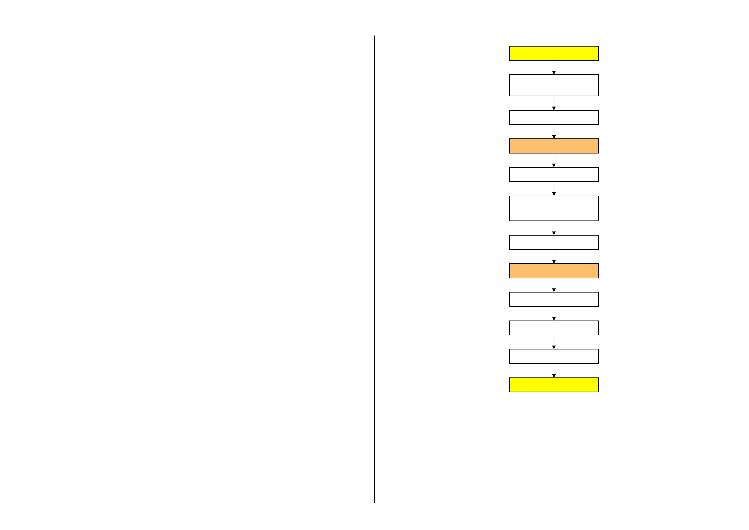
About unit with Internal Memory Model
After the board replacement, execute the procedure below first.
1. Execute the [DESTINATION DATA WRITE] of ADJUST tab in the Adjust Manual.
2. Execute the script files below. (Refer to the flowchart in Fig. 1)
• 11DdmMmcReadTestMINI_v4.vbe
• 11DdmMmcMakePartition_v4.vbe
Note: Download the script files from TISS Homepage.
When searching in the TISS Homepage, enter “IM_VC_TOOL” for keyword in the Part Number field.
Unless these script files are executed, the following symptoms may appear.
Make sure execute the above script files.
• The internal memory is not recognized as a media.
• The management file saved in the internal memory model cannot be repaired.
• The internal memory cannot be formatted.
Reactive the camcorder automatically
Disconnect the USB cable,
and turnoff the power switch.
END
Fig.1
HDR-CX190/CX190E/CX200/CX200E/CX210/CX210E/PJ200/PJ200E/PJ210_L2
1-1
Page 6
Ver. 1.1 2012.01
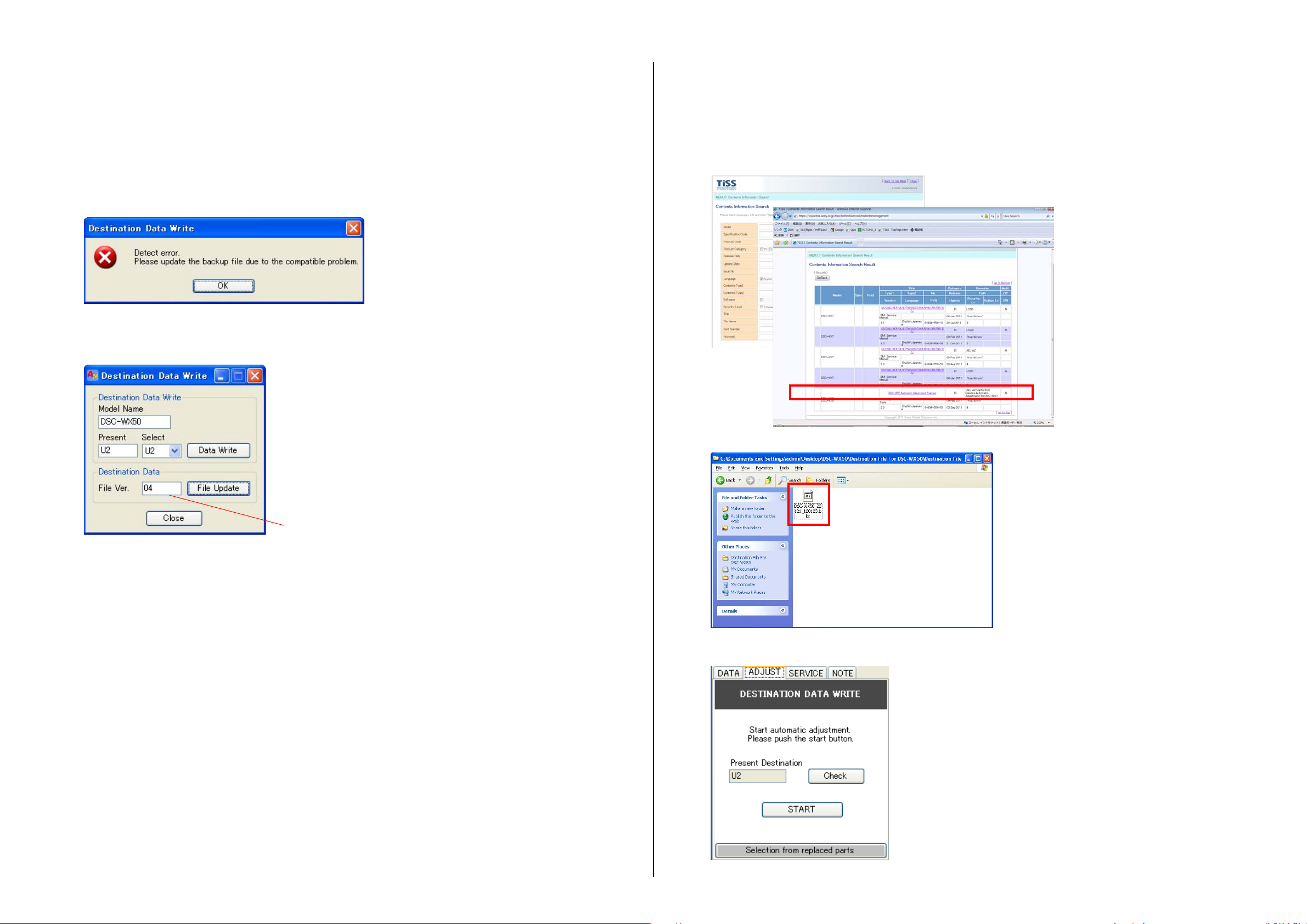
1-3. ADDITION OF DESTINATION DATA FILE
If the Destination Data file included in the Adjust manual is old, “DESTINATION DATA WRITE” cannot be executed in some cases.
In that case, download a new Destination Data file from the TISS homepage according to the following procedure.
– ENGLISH –
3) Search the model whose new Destination Data file you want to get on the TISS homepage.
When the Destination Data file has been updated, a file with a name “Destination File For ‘model name’.zip” is registered.
(Example) Destination File For DSC-WX50.zip
Note 1: To perform Destination Data Write for this model, the Adjust manual of the DSC-WX50 series must have been installed.
Install the Adjust manual of the DSC-WX50 series in advance.
Note 2: The actual image may differ from the image shown above.
1) If the Destination Data file in the Adjust manual in use is old, the window shown in Fig. 1 is displayed.
Click the [OK] button.
Fig. 1
2) The Destination Data Write window opens.
Check the version of the Destination Data file retained in the Adjust manual.
Furthermore, the version supported by the Destination Data file is shown in the Remarks column.
Note : If the Destination Data file has not been updated, contact the Service Headquarters.
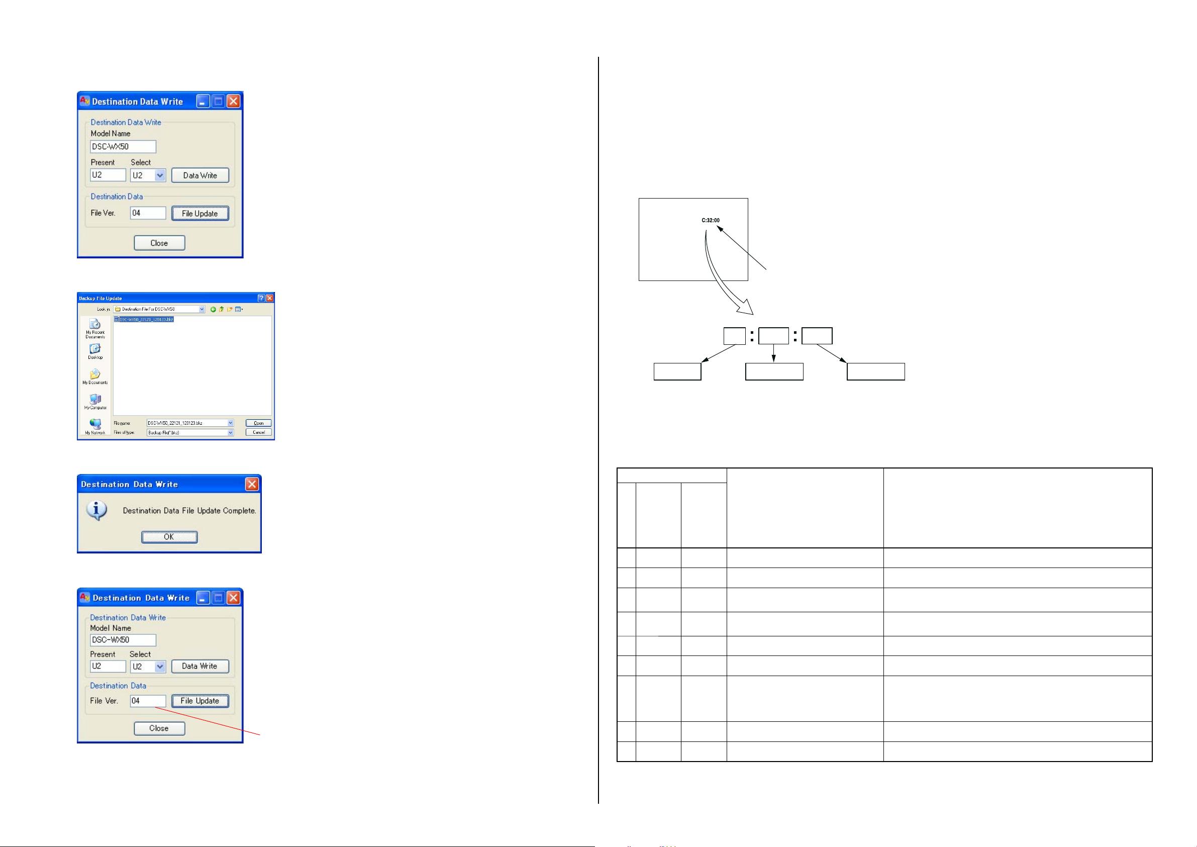
4) Download the Destination Data file of the relevant model and unzip the file.
Destination Ver. window
5) Execute “DESTINATION DATA WRITE” in the Adjust tab of the Adjust manual.
Click the [START] button.
HDR-CX190/CX190E/CX200/CX200E/CX210/CX210E/PJ200/PJ200E/PJ210_L2
1-2
Page 7
Ver. 1.1 2012.01
The changed portions from
Ver. 1.0 are shown in blue.
6) Click the [File Update] button in the window.
1-4. SELF-DIAGNOSIS FUNCTION
1-4-1. Self-diagnosis Function
When problems occur while the unit is operating, the self-diagnosis
function starts working, and displays on the LCD screen what to do.
This function consists of two display; self-diagnosis display and service
mode display.Details of the self-diagnosis functions are provided in the
Instruction manual.
LCD screen
– ENGLISH –
1-4-2. Self-diagnosis Display
When problems occur while the unit is operating, the counter of the LCD
screen shows a 4-digit display consisting of an alphabet and numbers,
which blinks at 3.2 Hz. This 5-character display indicates the “repaired
by:”, “block” in which the problem occurred, and “detailed code”of the
problem.
7) A file selection screen opens. Select the Destination Data file to be added and click the [Open] button.
8) When the file has been successfully added, the following window opens.
9) Check the Destination Ver. window and confirm that the version has been updated.
Blinks at 3.2 Hz
00
Detailed Code
Refer to “1-4-3. Self-diagnosis Code Table”.
Repaired by:
C : Corrected by customer
E : Corrected by service
engineer
32C
Block
Indicates the appropriate
step to be taken.
E.g.
13 ....
Format the “memory card”.
32 ....Turn on power again.
1-4-3. Self-diagnosis Code Table
Self-diagnosis Code
Block
Function
Repaired by:
C 0 4 0 0 Non-standard battery is used. Use the InfoLITHIUM battery.
C 0 6 0 0 The battery pack temperature is high. Change the battery pack or place it in a cool place.
C1 3 0 1
C 1 3 0 2 Access error
C 1 3 0 3 Access error (External mdedia) Turn power off and turn power on again.
Detailed
Code
Memory card is unformatted.
Memory card is broken.
*
*
Symptom/State Correction
Format the memory card.
Insert a new memory card.
Remove the power source. Reconnect it again and operate your camcorder again.
Destination Ver. window
HDR-CX190/CX190E/CX200/CX200E/CX210/CX210E/PJ200/PJ200E/PJ210_L2
C 1 3 0 4 Drive fault (External mdedia) Turn power off and turn power on again.
CE32
( )
61
E 2 0 0 0 Flash memory data are rewritten. Make flash memory data correct value. (Note 1)
E 3 1 0 0 Drive fault Turn power off and turn power on again.
Note 1: Start the Adjust Manual in the Adjust Station and refer to the “DESTINATON DATA WRITE”.
Note 2: Functions of codes with * mark are not provided in this unit.
*
60
00
*
Difficult to adjust focus
(Cannot initialize focus)
1-3
Retry turn the power on by the power switch. If it does not recover,
check the focus drive signal of lens block (pin wa to wf of CN1005 on
the VC-651 board). If it is OK, check the focus motor drive IC (IC5306
on the VC-651 board).
Page 8

Ver. 1.1 2012.01
The changed portions from
Ver. 1.0 are shown in blue.
Self-diagnosis Code
– ENGLISH –
Self-diagnosis Code
Block
Function
Detailed
Code
Repaired by:
E6 1 1 0
E6 1 1 1
E6 1 3 0
E6 2 0 0
E6 2 0 1
Symptom/State Correction
Zoom operations fault
(Cannot initialize zoom lens.)
The abnormalities in initialization of the focus
lens and the abnormalities in initialization of
the zoom lens occurred simultaneously.
Reset position detection error on the stepper
iris initializing
Handshake correction function does not work
well. (With PITCH angular velocity sensor
output stopped.)
Handshake correction function does not work
well. (With YAW angular velocity sensor
output stopped.)
Inspect the lens block zoom drive signal (pin 1 to 4 of CN1005 on
the VC-651 board, when zooming is performed when the zoom lever is
operated, and the zoom motor drive IC (IC5306 on the VC-651 board)
when zooming is not performed.
Check both C: 32: 60 and E: 61: 10 of the self-diagnosis code.
Turn the power on to open lens barrier . Disconnect the battery or power
cord, and then connect again.
Confirm that the iris blades in lens are working.
If iris blades do not working, check the iris motor drive IC in lens drive
block (CN1005 pin qd to qk on the VC-651 board).
If iris blades work normally, confirm that they are closing completely
and confirm following item.
・ Case of the iris blades do not close normally Replace the lens block).
・ Case of “E: 61: 30” is appeared and iris blades closed completely.
Confirm that communication with lens block is normal.
・ Case of LCD is not displayed normally Check that connection
between CN6805 on the CM-127 board and CN1002 and VC-651
board by FP-1483 flexible board.
・ Case of LCD is displayed normally Replace the lens block.
Inspect PITCH angular velocity sensors (SE7501 on the CM-127
board) peripheral circuits.
Inspect YAW angular velocity sensors (SE7501 on the CM-127 board)
peripheral circuits.
Block
Function
Detailed
Code
Symptom/State Correction
Repaired by:
E 9 5 0 0 GPS hardware error Turn power off and turn power on again.
E 9 6 0 0 Map area mount error Turn power off and turn power on again.
*
*
E 9 7 0 0 Projector hardware error Turn power off and turn power on again.
Note 3: When the lens block was replaced, start the Adjust Manual in the Adjust Station and execute the necessary adjustment items.
After the adjustment, make sure with the STEADYSHOT turned ON that the steadyshot functions appropriately in the handheld operation.
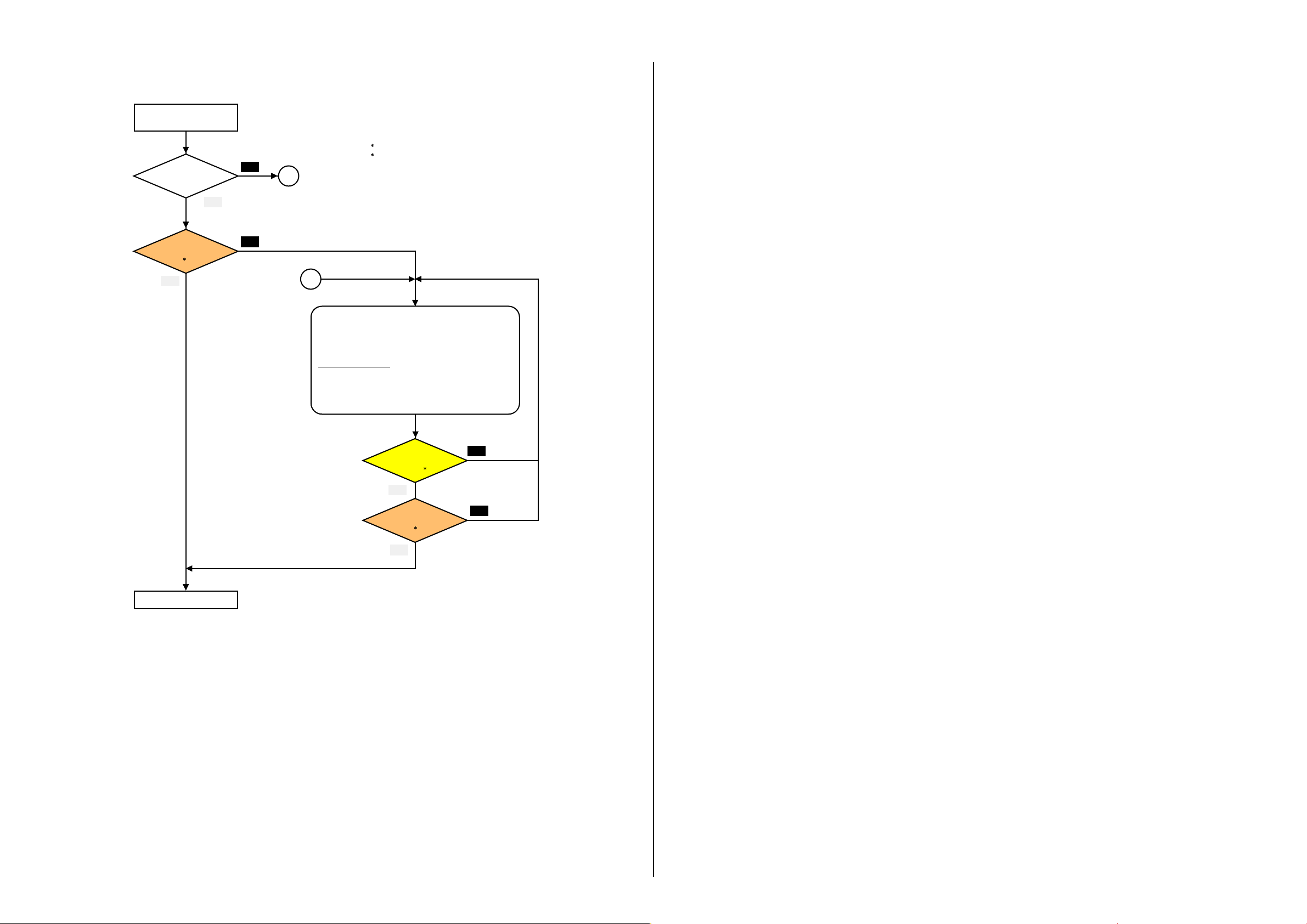
1-5. NOTE ON REPLACING PROJECTOR UNIT (HDR-PJ200/PJ200E/PJ210)
Refer to the following flowchart when repairing or inspecting the projector’s projection function.
If you have received an indication on the projector’s projection function from the customer, check defective part according to the following flowchart.
When a defective part has been clarified, repair the projector according to the check result.
Note 1: The projector unit (copper plate in particular) becomes hot after it is used.
When replacing a part of the projector unit, wait until it is cooled down.
Wipe the lens gently with a soft cloth such as a cleaning cloth or glass cleaning cloth.
Note 2: Stubborn stains may be removed with a soft cloth such as a cleaning cloth or glass cleaning cloth lightly dampened with water.
Never use a solvent such as alcohol, benzene or thinner; acid, alkaline or abrasive detergent; or a chemical cleaning cloth, as they will damage the lens sur-
face.
Projector problem checking procedure (other than indication on brightness)
E 6 2 0 2 Abnormality of IC for steadyshot. Turn power off and turn power on again.
E6 2 0 3
E6 2 0 4
E 6 2 1 0 Shift lens initializing failure.
IC for steadyshot and micro controller com-
*
munication abnormality among.
Image vibration correction during handshake
function does not work.
Turn power off and turn power on again.
Inspect the image vibration angular velocity sensors (SE7501 in the
CM-127 board) peripheral circuits.
Replacement of lens block. (Note 3)
If an error occurs again, replace the VC-651 board.
E 6 2 1 1 Shift lens overheating (Pitch) Turn power off and turn power on again.
E 6 2 1 2 Shift lens overheating (Yaw) Turn power off and turn power on again.
E 6 2 2 0 Abnormality of thermistor. Turn power off and turn power on again.
E 9 1 0 1 Abnormality when flash is beingcharged. Turn power off and turn power on again.
E 9 1 0 2 Abnormality of LED Video light. Turn power off and turn power on again.
E9 1 0 3
*
*
*
Abnormality of LED Video light Temperature detection.
Turn power off and turn power on again.
Check the remaining battery power because this symptom maybe
depended on the remaining battery level, and confirm whether or
E9 2 0 1
Battery current value goes over the max
discharge current
not the symptom is occurred after replacing the battery. If the symptom is still occurred, overhaul inspection is needed. Check each
output of DC/DC converter (IC4301 on the VC-651 board) on with
connected the DC JACK (J1001).
(The minimum connection to periphery)
E9 4 0 0
Fault of writing or erasing the flash memory
E 9 4 0 1 Internal flash memory fault
E 9 4 0 2 BGM data error Check the CPU (IC1301 on the VC-651 board).
*
IM Model:
Inspect the flash memory (IC8101, IC8201 on the MM-102 board).
IM Model:
Inspect the flash memory (IC8101, IC8201 on the MM-102 board).
Indicated defective
projector received
Indication on
brightness
No
B
Yes
Measure brightness.
( 2)
OK OK
END
(See page 1-5)
NG
A
(See page 1-5)
Inspect projector
LED.
( 1)
1 Refer to the ADJUST tab of Adjust Manual.
2 Refer to the SERVICE tab of Adjust Manual.
NG
-
Replace projector unit (light emitting block). (*1)
-
Replace PJ board. (*1)
-
Replace both projector unit (light emitting block)
and PJ board. (*1)
Projector Data Input
-
Fixed value input
Enter the number on the label attached to the unit.
-
Serial number input
LD40Syywwnnnnn Enter the red part.
Inspect projector
LED.
( 1)
OK
NG
HDR-CX190/CX190E/CX200/CX200E/CX210/CX210E/PJ200/PJ200E/PJ210_L2
1-4
Page 9
Projector problem checking procedure (indication on brightness)
– ENGLISH –
– JAPANESE –
1-1. 修理時の電源供給について
Indicated defective
projector received
Indication on
brightness
Yes
Measure brightness.
( 2)
OK
END
No
B
NG
(See page 1-4)
1 Refer to the ADJUST tab of Adjust Manual.
2 Refer to the SERVICE tab of Adjust Manual.
(See page 1-4)
A
-
Replace projector unit (light emitting block). (*1)
-
Replace PJ board. (*1)
-
Replace both projector unit (light emitting block)
and PJ board. (*1)
Projector Data Input
-
Fixed value input
Enter the number on the label attached to the unit.
-
Serial number input
LD40Syywwnnnnn Enter the red part.
Inspect projector
LED.
( 1)
OK
Measure brightness.
( 2)
OK
NG
NG
本機では,安定化電源(8.4Vdc)からバッテリ端子に電源を供給した場合,約10秒後にシャットオフし,動作しなくなります。
これを避けるため,下記の方法を用いてください。
方法:
ACアダプタを使用する。
注意: 基板交換時は、最初に仕向けデータの変更を行う必要があります。
仕向けデータの変更はAdjustManualのADJUSTタブにある、「DESTINATIONDATAWRITE」を実行してください。
1-2. VC-651基板交換時の注意
基板交換時は,下記の点に注意してください。
仕向けデータ
補修用基板と交換する時,補修用基板に書かれている仕向けデータは元の設定と違っている場合があります。
AdjustStationからAdjustManualを起動させて「DESTINATIONDATAWRITE」を実行させてください。
補修用基板交換後、電源を入れると内蔵記録メディアエラーが表示される場合がありますが、「DESTINATIONDATAWRITE」を実行
させると消えます。「DESTINATIONDATAWRITE」実行しても消えない場合は、内蔵記録メディアをフォーマットしてください。
USBシリアルセーブ
補修用基板と交換する時,交換前の基板よりUSBシリアルNo.を取得してください。
データの取得はAdjustStationからAdjustManualを起動させて「USBSERIALSAVE」を実行させてください。
USBシリアルNo.
セットは,1台毎に異なる固有のID(USBSerialNo.)を書き込んだ後,出荷されています。
新品の補修用基板には,このIDが書き込まれていないので,基板交換後にIDを入力する必要があります。
AdjustStationからAdjustManualを起動させて「USBSERIALNo.INPUT」を実行させてください。
プロジェクター用のデータ(HDR-PJ200/PJ200E/PJ210)
補修用基板と交換する時,交換前の基板より下記のデータを取得してください。
・Fixedvalue(プロジェクターの照射性能を示す値)。
・Serialnumber(プロジェクターユニットの製造シリアル番号)。
データの取得はAdjustStationからAdjustManualを起動させて、[DATA]タブにある[ProjectorDataReference]を参照してください。
内蔵メモリー搭載機について
補修用基板に交換後は,最初に下記の手順を実行してください。
1. AdjustManualのADJUSTタブにある,「DESTINATIONDATAWRITE」を実行する。
2. 下記のスクリプトファイルを実行する。
・11DdmMmcReadTestMINIv4.vbe
・11DdmMmcMakePartitionv4.vbe
Note: スクリプトファイルはTISSホームページより入手してください。
TISSホームページで検索する際はPartNumber欄に「IMVCTOOL」と入 力して検索してください。
HDR-CX190/CX190E/CX200/CX200E/CX210/CX210E/PJ200/PJ200E/PJ210_L2
このスクリプトファイルを実行しなかった場合,以下のような症状が発生する可能性があります。
必ず上記のスクリプトを実行してください。
・内蔵メモリーがメディアとして認識できない
・内蔵メモリー内に保存されている,管理ファイルの修復ができない
・内蔵メモリーのフォーマットができない
1-5
Page 10

Ver. 1.1 2012.01
START
セットをPCにUSB接続し、電源を入れる
* PCはSeusEX がインストール済で,
SeusEXへの接続が可能であること
– JAPANESE –
1-3. DestinationDataファイルの追加について
Adjustmanualに含まれるDestinationDataファイルが古い場合,「DESTINATIONDATAWRITE」が実行できないことがあります。
その場合は,下記の手順を参考にして,TISSホームページより新しいDestinationDataファイルを入手してください。
Note1: この機種で仕向け設定を行うには,DSC-WX50シリーズのAdjustmanualがインストールされている必要があります。
先にDSC-WX50シリーズのAdjustmanualをインストールしてください。
Note2: 手順中の画像は実際と異なる場合があります。
USB接続を選択し、
USB接続を行う
DdmMmcReadTestMINI.vbe
を実行
(数秒後)
SetOverallReadMINI OK表示
電源を入れたまま、
ACアダプタを抜き挿しする
処理は自動で実行される
(Blue画面)
(約10秒後)
セットが自動的に再起動される
11DdmMMCMakePartition.vbe
を実行
(数秒後)
MakePartition OK表示
1) 使用しているAdjustmanualのDestinationDataファイルが古い場合,Fig.1のようなウインドウが表示される。
[OK]ボタンをクリックする。
Fig. 1
2) DestinationDataWriteウインドウが表示される。
Adjustmanualの保持しているDestinationDataファイルのバージョンを確認する。
セットが自動的に再起動される
USB接続を解除し、電源を切る
END
Fig.1
Destination Ver. ウインドウ
HDR-CX190/CX190E/CX200/CX200E/CX210/CX210E/PJ200/PJ200E/PJ210_L2
1-6
Page 11

Ver. 1.1 2012.01
3) TISSホームページにて,新しいDestinationDataファイルを入手したい機種を検索する。
DestinationDataファイルが更新されている場合,「DestinationFileFor”機種名”.zip」という名称のファイルが登録されてい
る。
(例)DestinationFileForDSC-WX50.zip
また,Remarks欄にはこのDestinationDataファイルが対応するバージョンが記載されています。
Note:バージョンが更新されていなかった場合は,サービスヘッドクォーターへお問い合わせください。
– JAPANESE –
6) ウインドウ内の[FileUpdate]ボタンをクリックする。
7) ファイルを選択する画面が出るので,追加するDestinationDataファイルを選択し,[開く]ボタンをクリックする。
4) 該当機種のDestinationDataファイルをダウンロードし,解凍する。
5) AdjustmanualのAdjustタブにある,「DESTINATIONDATAWRITE」を実行する。
[START]ボタンをクリックする。
8) ファイルの追加が成功すると,下記のような画面が出る。
9) DestinationVer.ウインドウを確認し,バージョンが更新されていることを確認する。
HDR-CX190/CX190E/CX200/CX200E/CX210/CX210E/PJ200/PJ200E/PJ210_L2
Destination Ver. ウインドウ
1-7
Page 12

Ver. 1.1 2012.01
The changed portions from
V
er. 1.0 are shown in blue.
1-4. 自己診断機能
1-4-1.自己診断機能について
本機の動作に不具合が生じたとき,自己診断機能が働き,LCD
画面に,どう処置したらよいか判断できる表示を行います。「自
己診断表示」と「サービスモード表示」の2つの表示があります。
自己診断機能については取扱説明書にも掲載されています。
LCD画面
3.2 Hz点滅
00
詳細コード
「1-4-3. 自己診断コード表」を参照
対応者分類
C:お客さま自身で対応
E:サービスエンジニア
で対応
C23
ブロック分類
対応方法の違いにより分類
例
・メモリーカードをフォーマットする・・31
32・・・電源を入れ直す
1-4-3. 自己診断コード表
自己診断コード
対
ブロック機能詳細
応
者
コード
C 0 4 0 0 標準以外のバッテリを使用している インフォリチウムバッテリを使用する。
C 0 6 0 0 バッテリが高温になっている バッテリを交換するか, バッテリを涼しいとこに置く。
フォーマットしていないメモリー
C1 3 0 1
カードを入れた
メモリーカードが壊れている
C 1 3 0 2 アクセスエラー 電源を外し,再度入れ直してから操作する。
C 1 3 0 3 アクセスエラー(外部メディア) 電源を入れ直す。
C 1 3 0 4 ドライブの異常(外部メディア) 電源を入れ直す。
CE32
( )
61
60
00
E2 00 0
E 3 1 0 0 ドライブの異常 電源を入れ直す。
注意1:AdjustStationからAdjustManualを起動させて「DESTINATIONDATAWRITE」を参照してください。
注意2:*マークのコードは本機には実装されていない機能です。
*
*
*
フォーカスが合いにくい
(フォーカスの初期化ができない)
フラッシュメモリが書き換えられて
いる
*
症状/状態 対応/方法
1-4-2.自己診断表示
本機の動作に不具合が生じたとき,LCD画面のカウンタ表示部
分がアルファベットと数字の4桁表示になり,3.2Hzで点滅しま
す。この5文字の表示によって対応者分類および不具合の生じ
たブロックの分類,不具合の詳細コードを示します。
メモリーカードをフォーマットする。
新しいメモリーカードに交換する。
操作スイッチの電源を入れ直す。
復帰しない場合,レンズブロックのフォーカス駆動信号(VC-651
基板CN1005wa〜wfピン)を点検する。
異常なければフォーカスモータ駆動回路(VC-651基板IC5306)
を点検する。
フラッシュメモリのデータを元の値に戻す。(注意1)
自己診断コード
対
応
者
ブロック
機能
詳細
コード
症状/状態 対応/方法
ズームレバーを操作したときにズーム動作をすれば,レンズブロッ
E6 11 0
ズーム動作の異常(ズームレン
ズの初期化ができない)
クのズーム駆動信号(VC-651基板CN10051〜4ピン)を点検する。
ズーム動作をしなければズームモータ駆動回路(VC-651基板IC5306)
を点検する。
E 6 1 1 1 フォーカス,ズーム異常 自己診断コードC:32:60とE:61:10の両方を点検する。
電源を入れてレンズバリアが開いている状態で、バッテリまたは電源ケーブル
をはずして付け直す。
その際、レンズ内のアイリス羽根が動作していることを確認する。
アイリス羽根が動作してない場合は、レンズドライブブロックのアイリスモー
タドライブ(VC-651基板CN1005
E61 30
E62 00
E62 01
E 6 2 0 2 手振れ補正用ICの異常 電源を入れ直す。
E62 03
E62 04
E 6 2 1 0 シフトレンズ初期化異常
E62 11
E62 12
E 6 2 2 0 サーミスタの異常 電源を入れ直す。
E 9 1 0 1 フラッシュの充電異常 電源を入れ直す。
E 9 2 0 2 LEDビデオライトの異常 電源を入れ直す。
E 9 3 0 3 LEDビデオライトの温度検出異常 電源を入れ直す。
E92 01
E94 00
E 9 4 0 1 フラッシュメモリ内部異常
E 9 4 0 2 BGMデータ異常 CPU(VC-651基板IC1301)を点検する。
E 9 5 0 0 GPSハード異常 電源を入れ直す。
E 9 6 0 0 地図領域マウント異常 電源を入れ直す。
E 9 7 0 0 プロジェクタハード異常 電源を入れ直す。
注 意 3: レンズブロックを交換した場合 は,AdjustStationからAdjustManualを起動させて必要な調整項目を実施すること。
調整後は手振れ補正ONの状態にして,手持ち動作で手振れ補正が適切に動作していることを確認する。
ステッパIRISイニシャル時リセット
位置検出異常
手振れ補正が効きにくい(PITCH角速
度センサ出力張り付き)
手振れ補正が効きにくい(YAW角速
度センサ出力張り付き)
手振れ補正用ICとマイクロコント
*
ローラーとの通信異常
Active手振れ補正時の画ゆれが補正
できない
(角速度センサ出力張り付き)
シフトレンズオーバーヒート
(PITCH)
シフトレンズオーバーヒート
(YAW)
*
*
*
(バッテリーの)電流値が最大放電電
流を超えた
フラッシュメモリの書込み/消去動作不良IMModel:
*
*
*
アイリス羽根が動作する場合は、アイリス羽根が完全に閉じきることを確認し、
以下の内容を確認する。
・アイリス羽根を正常に閉じることができない場合レンズブロックを交換す
る。
・アイリス羽根は正常に閉じているが、E:61:30が出る場合CMOSブロック組
立との通信ができているかを確認する。
・正常に画面が出ていない場合CM-127基板 のCN6805とVC-651基 板 の
CN1002がFP-1483フレキシブル基板で接続されているかを確認する。
・正常に画面が出ている場合レンズブロックを交換する
PITCH角速度センサ(CM-127基板SE7501)周辺回路を点検する。
YAW角速度センサ(CM-127基板SE7501)周辺回路を点検する。
電源を入れ直す。
画ゆれ検出角速度センサ(CM-127基板SE7501)周辺回路を点検する。
レンズブロックを交換する。
(注意3)エラーが再度発生する場合は,VC-651基板を交換する。
電源を入れ直す。
電源を入れ直す。
バッテリ残量に依存する場合があるので,バッテリ残量を確認する。次にバッ
テリを交換して症状が出るか確認する。バッテリを交換しても症状が出る場合
は,エラー発生後に電源が切れてしまうため,分解して確認する。DCジャッ
ク(J1001)をVC-651基板に接続した状態(最小限の接続)でDC/DCコンバー
タ(VC-651基板IC4301)の各チャンネル出力を確認する。
フラッシュメモリ(MM-102基板IC8101,IC8201)を点検する。
IMModel:
フラッシュメモリ(MM-102基板IC8101,IC8201)を点検する。
qd
ピン)を点検する。
qk
〜
– JAPANESE –
HDR-CX190/CX190E/CX200/CX200E/CX210/CX210E/PJ200/PJ200E/PJ210_L2
1-8
Page 13

Ver. 1.1 2012.01
The changed portions from
Ver. 1.0 are shown in blue.
1-5. プロジェクターユニット交換時の注意(HDR-PJ200/PJ200E/PJ210)
– JAPANESE –
プロジェクターの不具合確認手順(明るさに関する指摘の場合)
プロジェクター投影機能のサービス、点検時には下記のフローを参照してください。
お客様よりプロジェクター投影機能に関する指摘を受けた場合は、下記のフロー沿って不具合箇所を確認してください。
その確認結果に従って、修理を行ってください。
注意1:プロジェクターを使用した後は、プロジェクターユ ニットが熱くなっています 。
特に銅板の部分は高温になります。
部品を交換する時は、温度が下がってから作業を行ってください。
注意2:プロジェクターのレンズ表面についた汚れは、メガネ拭きやクリーニングクロス等の柔らかい布で軽く拭いてください。
汚れがひどいときは、メガネ拭きやクリーニングクロス等の柔らかい布に水を少し含ませて、拭きとってください。
アルコールやベンジン、シンナー、酸性洗浄液、アルカリ性洗浄液、研磨剤入り洗浄剤、化学ぞうきん等は
レンズ表面を傷めますので、絶対に使用しないでください。
プロジェクターの不具合確認手順(明るさに関する指摘以外の場合)
プロジェクター不具合の
指摘品受付
1 Adjust manualのADJUSTタブを参照
2 Adjust manualのSERVICEタブを参照
明るさに
関する指摘
No
B
Yes
明るさの測定
( 2)
NG
A
Projector LED
検査 ( 1)
NG
プロジェクター不具合の
指摘品受付
明るさに
関する指摘
Yes
明るさの測定
( 2)
OK
No
NG
B
A
・
・
・
Projector Data Input
・
・
1 Adjust manualのADJUSTタブを参照
2 Adjust manualのSERVICEタブを参照
プロジェクターユニット(LED発光部)を交換する (*1)
PJ基板を交換する(*1)
プロジェクターユニット(LED発光部)とPJ基板の
両方を交換する(*1)
Fixed valueの入力
ユニット上の貼付シールに記載されている番号を入力
シリアルNoの入力
LD40Syywwnnnn 赤字部分の入力
OK OK
修理完了
・
プロジェクターユニット(LED発光部)を交換する (*1)
・
PJ基板を交換する(*1)
・
プロジェクターユニット(LED発光部)とPJ基板の
両方を交換する(*1)
Projector Data Input
・
Fixed valueの入力
ユニット上の貼付シールに記載されている番号を入力
・
シリアルNoの入力
LD40Syywwnnnn 赤字部分の入力
Projector LED
検査 ( 1)
OK
NG
修理完了
Projector LED
検査 ( 1)
OK
明るさの測定
( 2)
OK
NG
NG
HDR-CX190/CX190E/CX200/CX200E/CX210/CX210E/PJ200/PJ200E/PJ210_L2
1-9E
Page 14

2. REPAIR PARTS LIST
IDENTIFYING PARTS
Follow the disassembly in the numerical order given.
1 USB Cabinet
IM Model
5 MM-102 Board
3 MS Lid
8 Cabinet (L)
2 Top Cabinet Assy
7 Lens Block
• CM-127 Board
• FP-1483 Flexible Board
Projector Model
6 Cabinet (R) Section
• PD-457 Board
• PJ-104 Board
• FP-1319 Flexible Board
• FP-1482 Flexible Board
(ENGLISH)
NOTE:
• -XX, -X mean standardized parts, so they may have some differences from the original
one.
• Items marked “*” are not stocked since they are seldom required for routine service.
Some delay should be anticipated when ordering these items.
• The mechanical parts with no reference number in the exploded views are not supplied.
• Due to standardization, replacements in the parts list may be different from the parts
specified in the diagrams or the components used on the set.
• CAPACITORS:
uF: μF
• COILS
uH: μH
• RESISTORS
All resistors are in ohms.
METAL: metal-film resistor
METAL OXIDE: Metal Oxide-film resistor
F: nonflammable
• SEMICONDUCTORS
In each case, u: μ, for example:
uA...: μA... , uPA... , μPA... ,
uPB... , μPB... , μPC... , μPC... ,
uPD..., μPD...
(JAPANESE)
【使用上の注意】
•ここに記載されている部品は,補修用部品であるため,回路図及び
セットに付いている部品と異なる場合があります。
•-XX,-Xは標準化部品のため,セットに付いている部品と異なる場合
があります。
•*印の部品は常備在庫しておりません。
•抵抗の単位Ωは省略してあります。
金 被:金属被膜抵抗。
サンキン:酸化金属被膜抵抗。
•インダクタの単位でuHはμHを示します。
•半導体の名称でuA...,uPA...,uPB...,uPC...,uPD...等はそれぞれμ
A...,μPA...,μPB...,μPC...,μPD...を示します。
The components identified by mark 0
or dotted line with mark 0 are critical for
safety.
Replace only with part number specified.
Les composants identifiés par une marque
0 sont critiques pour la sécurité.
Ne les remplacer que par une pièce portant
le numéro spécifié.
• Color Indication of Appearance Parts
Example:
(SILVER) : Cabinet’s Color
(Silver) : Parts Color
印の部品,または0印付の点線で囲ま
0
れた部品は,安全性を維持するために,
重要な部品です。
従って交換時は,必ず指定の部品を使用
してください。
• 外装部品色表示
例:
(SILVER):セットの色を表す。
(Silver) :部品の色を表す。
4 Front Block
Link
q; VC-651 Board
9 MS-475 Board
Non Projector Model
6 Cabinet (R) Section
• PD-454 Board
• FP-1481 Flexible Board
ACCESSORIES ASSEMBLY
• Abbreviation
AUS : Australian model
BR : Brazilian Model
CH : Chinese model
CND : Canadian model
HK : Hong Kong model
J : Japanese model
JE : Tourist model
KR : Korea model
NE : North European model
View Position
Left View
Front View
Top View
Back View
Right View
Bottom View
HDR-CX190/CX190E/CX200/CX200E/CX210/CX210E/PJ200/PJ200E/PJ210_L2
2-1
Page 15

NOTE FOR REPAIR
• Make sure that the flat cable and flexible board are not cracked of
bent at the terminal.
Do not insert the cable insufficiently nor crookedly.
• When remove a connector, don’t pull at wire of connector . It is possible
that a wire is snapped.
• When installing a connector, don’t press down at wire of connector.
It is possible that a wire is snapped.
• Do not apply excessive load to the gilded flexible board.
Cut and remove the part of gilt
which comes off at the point.
(Be careful or some
pieces of gilt may be left inside)
– ENGLISH –
修理時の注意
• フラットケーブルおよびフレキシブル基板の端子面に欠け,折れ等
がないことを確認する。
また,コネクタへの接続は,差し込み不足や斜め差しにならないよ
うに注意する。
• コネクタを取り外す時に,線材部(極細)を持って引っ張ると断線す
る恐れがありますので,絶対に線材部(極細)を持って引っ張らない
でください。
• 線材部(極細)を押さえながらコネクタを差し込むと,線材部(極細)
が断線する恐れがありますので,絶対に線材部(極細)には負担をか
けないでください。
• 金メッキされているフレキシブル基板には,強い負担をかけないで
ください。
– JAPANESE –
వ┵ߩ߇ࠇߚࡔ࠶ࠠㇱߪࠞ࠶࠻ߒߡ
వ┵ߩ߇ࠇߚࡔ࠶ࠠㇱߪࠞ࠶࠻ߒߡ
㒰ߒߡߊߛߐޕ
㒰ߒߡߊߛߐޕ
㧔ࡔ࠶ࠠ⎕ ߇ࠦࡀࠢ࠲ౝߦᱷߞߡࠆ
㧔ࡔ࠶ࠠ⎕ ߇ࠦࡀࠢ࠲ౝߦᱷߞߡࠆ
႐ว߽ࠆߩߢᵈᗧߒߡߊߛߐ㧕
႐ว߽ࠆߩߢᵈᗧߒߡߊߛߐ㧕
HDR-CX190/CX190E/CX200/CX200E/CX210/CX210E/PJ200/PJ200E/PJ210_L2
2-2
Page 16
1
Ver. 1.2 2012.05
The changed portions from
Ver. 1.1 are shown in blue.
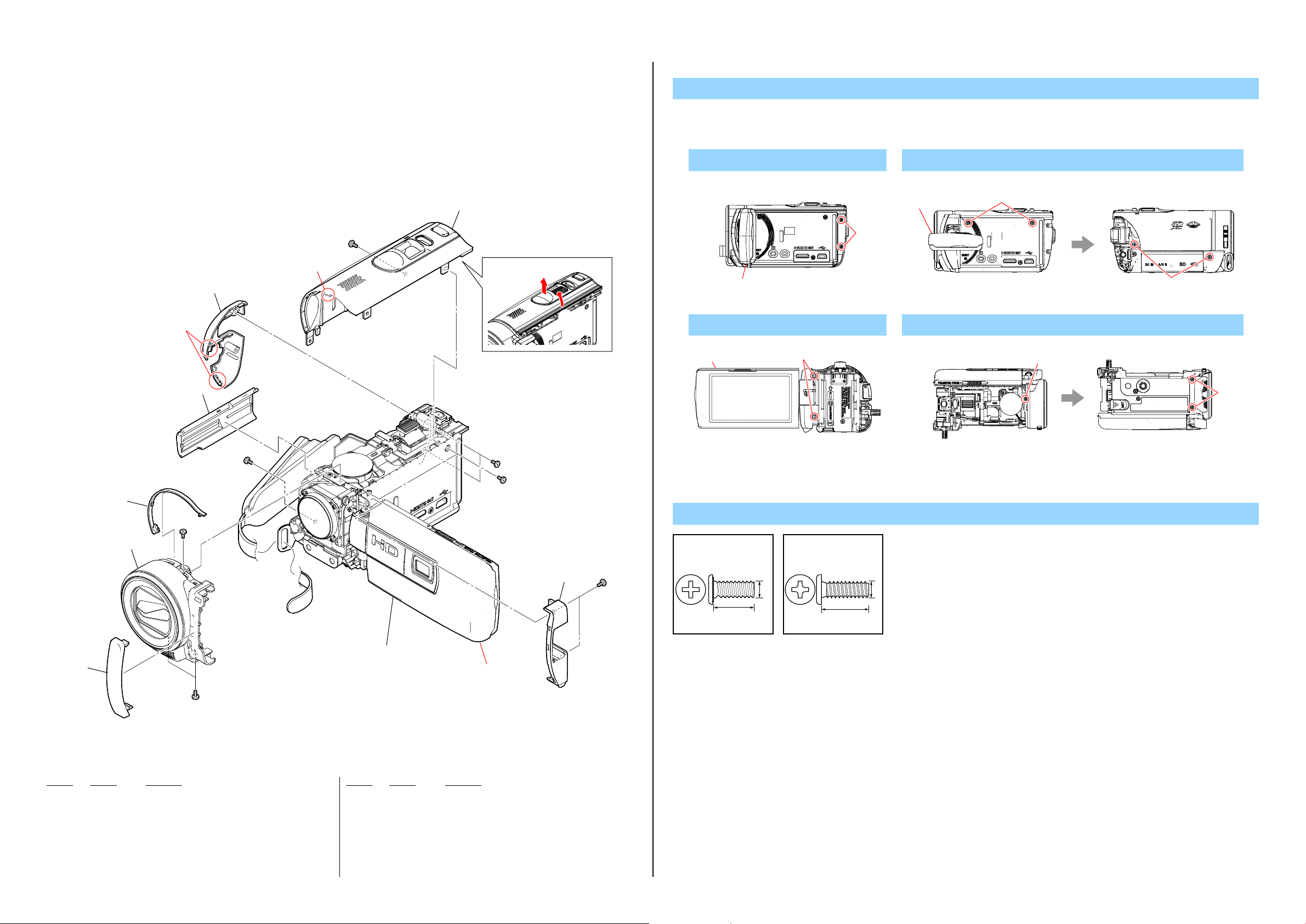
2-1. EXPLODED VIEWS
2-1-1. OVERALL SECTION-1
(Projector Model)
Refer to page 2-4 about Non Projector Model
1 5
1 (Claws)
3 4
2 (Claw)
#2
2 6
2
1
DISASSEMBLY
1. Remove to numerical order (1 to 5) in the left figure.
1 Open the LCD (1) → #12 X 2
Right View
#12
4 Open the LCD (4) → #2 X 2
4
Back View
#2
2 Rotate the LCD (2) → #2 X 4
Right View Left View
2
#2
5 #2 X 3
Top View Bottom View
#2
#2
#2
#2
3
#2
5 2
1
#2
Refer to page 2-4 about Non Projector Model
Overall Section-2
(Projector Model)
(See Page 2-5)
#12
#2
124
4 7
#2
Screw
#2: M1.7 X 4.0
(Black)
2-635-562-31
4.0
#12:M1.7 X 5.0 (Tapping)
(Black)
3-080-204-21
1.7
1.7
5.0
Ref. No. Part No. Description
1 4-412-130-01 ORNAMENT (2781), COVER (R)
2 A-1855-267-A PANEL ASSY (2781B), F (BLACK)
2 A-1861-022-A PANEL ASSY (2781S), F (SILVER)
3 4-412-135-01 BELT, FRONT
4
4-412-131-01 LID, MS
Ref. No. Part No. Description
5 4-412-136-01 CABINET, USB
6 A-1857-765-A CABINET ASSY (2781B), TOP (BLACK)
6 A-1861-018-A CABINET ASSY (2781S), TOP (SILVER)
7 4-412-129-01 COVER (R (2781)), HINGE (BLACK)
7 4-412-129-11 COVER (R (2781)), HINGE (SILVER)
#2 2-635-562-31 SCREW (M1.7)
#12 3-080-204-21 SCREW, TAPPING, P2
HDR-CX190/CX190E/CX200/CX200E/CX210/CX210E/PJ200/PJ200E/PJ210_L2
2-3
Page 17

DISASSEMBLY
2
2-1-2. OVERALL SECTION-1
(Non Projector Model)
Refer to page 2-3 about Projector Model
53
3
52
#2
2 (Claw)
1 (Claws)
2
#2
55
1
54
#2
#12
2
1
1. Remove to numerical order (1 to 4) in the left figure.
1 Open the LCD (1) → #12 X 2
Right View
#12
1
4 #2 X 3
Top View Bottom View
#2
2 Rotate the LCD (2) → #2 X 4
Right View Left View
#2
#2
#2
#2
51
4
56
58
57
57
#2
Overall Section-2
(Non Projector Model)
(See Page 2-6)
Refer to page 2-3 about Projector Model
Ref. No. Part No. Description
51 A-1855-293-A PANEL ASSY (278B), F (BLACK)
51 A-1855-294-A PANEL
51 A-1855-295-A PANEL ASSY (278R), F (RED)
51 A-1855-296-A PANEL ASSY (278S), F (SILVER)
52 4-412-135-01 BELT, FRONT
53 4-412-131-01 LID, MS
54 4-412-136-01 CABINET, USB
55 A-1854-710-A CABINET ASSY (278B), TOP
55 A-1854-711-A CABINET ASSY (278L), TOP
ASSY (278L), F (BLUE)
(CX200/CX200E/CX210/CX210E (BLACK))
(CX200/CX200E/CX210/CX210E (BLUE))
Ref. No. Part No. Description
55 A-1854-712-A CABINET ASSY (278R), TOP
55 A-1854-713-A CABINET ASSY (278S), TOP
55 A-1854-714-A CABINET ASSY (273B), TOP (CX190/CX190E)
56 X-2583-408-1 COVER (R) ASSY (278), HINGE
57 4-413-682-01 SHEET, HINGE COVER (R) ADHESIVE
58 4-412-127-01 COVER (R), HINGE
#2 2-635-562-31 SCREW (M1.7)
#12 3-080-204-21 SCREW, TAPPING, P2
HDR-CX190/CX190E/CX200/CX200E/CX210/CX210E/PJ200/PJ200E/PJ210_L2
12
(CX200/CX200E/CX210/CX210E (RED))
(CX200/CX200E/CX210/CX210E (SILVER))
2-4
Screw
#2: M1.7 X 4.0
(Black)
2-635-562-31
4.0
#12:M1.7 X 5.0 (Tapping)
(Black)
3-080-204-21
1.7
1.7
5.0
Page 18

DISASSEMBLY
2-1-3. OVERALL SECTION-2
(Projector Model)
Refer to page 2-6 about Non Projector Model
1
103
1
#12
106
107
IM Model
104
105
#2
#12
109
2
108
#11
110
3
Main Section
(See Page 2-7)
#12
1. Remove to numerical order (1 to 5) in the left figure.
1 Disconnect(1) → #12 X 3
Left View Left View
Disconnect
3 #11 X 2
Top View
#11
5 Disconnect(5-1) → #12 X 3 → Open the LCD (5-2) → #12 X 1
Disconnect
#12
5-1
2 #2 X 1 (IM Model)
#2
Left View
Claws
#12
Back ViewBottom View Right View
Left View
IM Model
4 (Claw)
5-1
102
101
Refer to page 2-6 about Non Projector Model
Ref. No. Part No. Description
101 4-412-116-01 CUSHION, MICROPHONE
102 4-412-122-01 HOLDER, MICROPHONE
103 4-413-125-01 BELT (S (K)), 12 TYPE GRIP
104 4-412-134-01 RETAINER, G BELT
105 4-412-133-01 SHEET METAL (REAR), G BELT
106 4-413-435-01 GASKET (MM) (IM Model)
107 1-885-623-11 FP-1557 FLEXIBLE BOARD (IM Model)
108 A-1852-422-A MM-102 (8G) BOARD, COMPLETE (IM Model)
109 4-412-124-01 CUSHION, SP
4
MIC901
Cabinet (R) Section-1
5
(Projector Model)
(See Page 2-8)
Ref. No. Part No. Description
110 4-412-119-01 PLATE, SP FIXED
MIC901 1-542-909-11 MICROPHONE UNIT
#2 2-635-562-31 SCREW (M1.7) (IM Model)
#11 3-078-890-11 SCREW, TAPPING
#12 3-080-204-21 SCREW, TAPPING, P2
HDR-CX190/CX190E/CX200/CX200E/CX210/CX210E/PJ200/PJ200E/PJ210_L2
#12
#12
5-2
2-5
Screw
#2: M1.7 X 4.0
(Black)
2-635-562-31
4.0
#11:M1.7 X 4.0 (Tapping)
(Silver)
3-078-890-11
1.7
4.0
#12
#12:M1.7 X 5.0 (Tapping)
(Black)
3-080-204-21
1.7
5.0
1.7
#12
5-2
#12
Page 19

DISASSEMBLY
2-1-4. OVERALL SECTION-2
(Non Projector Model)
Refer to page 2-5 about Projector Model
1
159
1
#12
156
IM Model
158
154
157
3
2
#2
152
161
160
155
#12
#11
Main Section
(See Page 2-7)
#12
1. Remove to numerical order (1 to 5) in the left figure.
1 Disconnect(1) → #12 X 3
Left View Left View
Disconnect
3 #11 X 2
Top View
#11
5 Disconnect(5-1) → #12 X 3→ Open the LCD (5-2) → #12 X 1
Disconnect
#12
5-1
2 #2 X 1
#2
Left View
Claws
#12
Back ViewBottom View Right View
Left View
IM Model
4 (Claw)
5-1
153
151
Refer to page 2-5 about Projector Model
Ref. No. Part No. Description
151 4-412-116-01 CUSHION, MICROPHONE
152 4-412-124-01 CUSHION, SP
153 4-412-122-01 HOLDER, MICROPHONE
154 1-885-623-11 FP-1557 FLEXIBLE BOARD (IM Model)
155 A-1852-422-A MM-102 (8G) BOARD, COMPLETE (IM Model)
156 4-413-435-01 GASKET (MM) (IM Model)
157 4-412-133-01 SHEET METAL (REAR), G BELT
158 4-412-134-01 RETAINER, G BELT
159 4-413-125-01 BELT (S (K)), 12 TYPE GRIP
160 4-412-123-01 HOLDER, SP
4
MIC901
Ref. No. Part No. Description
161 4-412-119-01 PLATE, SP FIXED
MIC901 1-542-908-11 MICROPHONE UNIT (CX190/CX190E)
MIC901 1-542-909-11 MICROPHONE UNIT (CX200/CX200E/CX210/CX210E)
#2 2-635-562-31 SCREW (M1.7) (IM Model)
#11 3-078-890-11 SCREW, TAPPING
#12 3-080-204-21 SCREW, TAPPING, P2
HDR-CX190/CX190E/CX200/CX200E/CX210/CX210E/PJ200/PJ200E/PJ210_L2
Cabinet (R) Section-1
5
(Non Projector Model)
(See Page 2-10)
#12
#12
5-2
2-6
Screw
#2: M1.7 X 4.0
(Black)
2-635-562-31
4.0
#11:M1.7 X 4.0 (Tapping)
(Silver)
3-078-890-11
1.7
4.0
#12
#12:M1.7 X 5.0 (Tapping)
(Black)
3-080-204-21
1.7
5.0
1.7
#12
5-2
#12
Page 20

Ver. 1.2 2012.05
2-1-5. MAIN SECTION
ns: not supplied
2
SP901
(Note 5)
#11
3
#11
212
213
211
#12
#11
209
208
BT8001
(Note 4)
CN901
204
214
207
223
#11
VC-651
204
206
#11
205
215
210
5
: BT8001 (LITHIUM SECONDARY BATTERY)
Board on the mount position.
(See page 6-30 of Level 3)
219
217
(Note 1, 2)
218
#172
DISASSEMBLY
1. Remove to numerical order (1 to 5) in the left figure.
1 #11 X 2
Left View
#11
5 #11 X 3
Top View
#11
4 #12 X 1 → #11 X 3
Bottom View
Bottom View Left View
#12
#11
#11
#11
BH8001
(Note 4)
ns
#11
1
216
4
203
202
#3
Caution :
Danger of explosion if battery is incorrectly replaced.
Replace only with the same or equivalent type.
Dispose of used batteries according to the instructions.
Ref. No. Part No. Description
201 4-412-118-01 PLATE, MS FIXED
202 4-412-126-01 SHEET METAL (FRONT), G BELT
203 A-1851-283-A MS-475 BOARD, COMPLETE
204 4-413-553-01 GASKET (MS)
205 3-283-643-01 SCREW, TRIPOD
206 4-412-121-01 HOLDER, MAIN
207 4-412-120-01 FRAME, MAIN
208 1-885-587-11 FP-1556 FLEXIBLE BOARD
209 4-412-125-01 SHEET, MS ACCESS
210 A-1852-423-A VC-651 BOARD, COMPLETE (CX190/CX190E)
210 A-1852-424-A VC-651 BOARD, COMPLETE
(CX200/CX200E/CX210/CX210E)
210 A-1852-425-A VC-651 BOARD, COMPLETE (Projector Model)
211 4-414-749-01 SHEET, TRIPOD
212 4-412-117-01 CABINET (L)
213 1-489-972-11 SWITCH BLOCK, CONTROL (PS27800)
214 1-838-712-21 CABLE, BUILT-IN USB
215 1-968-126-11 BATTERY CONNECTOR HARNESS
201
#11
電池の交換は、正しく行わないと破裂する恐れがあります。
電池を交換する場合には必ず同じ型名の電池又は同等品と交換してください。
使用済み電池は、取扱指示に従って処分してください。
Ref. No. Part No. Description
216 8-848-865-01 DEVICE, LENS LSV-1181A
217 1-856-061-21 OPTICAL FILTERBLOCK (OFB-06-12) (Note 1, 2)
218 4-163-258-01 RUBBER (1181), SEAL
219 A-1851-282-A CM-127 BOARD, COMPLETE
220 1-884-873-21 FP-1483 FLEXIBLE BOARD
221 4-412-055-01 SHEET, CM RADIATION (Note 3)
222 4-413-552-01 GASKET (CM)
223 4-419-529-01 TAPE (CN)
224 4-413-436-01 SHEET, CM PROTECTION
BH8001 1-251-928-21 SOCKET, BATTERY (Note 4)
BT8001 1-756-134-15 BATTERY, LITHIUM (SECONDARY) (Note 4)
CN901 1-842-324-11 JACK, DC
SP901 1-826-837-91 SPEAKER (1.3CM) (Non Projector Model) (Note 5)
SP901 1-858-075-41 SPEAKER (1.8CM) (Projector Model) (Note 5)
#3 2-660-401-01 SCREW (M1.7), NEW TRU-STAR, P2
#11 3-078-890-11 SCREW, TAPPING
#12 3-080-204-21 SCREW, TAPPING, P2
#172 2-178-410-01 TITE (UB TITE) 1.4
HDR-CX190/CX190E/CX200/CX200E/CX210/CX210E/PJ200/PJ200E/PJ210_L2
注意
224
221
(Note 3)
220
222
2-7
Screw
#3: M1.7 X 2.5
(Red)
2-660-401-01
2.5
#11:M1.7 X 4.0 (Tapping)
1.7
(Silver)
3-078-890-11
4.0
#12:M1.7 X 5.0 (Tapping)
(Black)
3-080-204-21
1.7
Note
Note 1: Be sure to read “Precautions for Replacement of Imager”
Note 1:
Note 2: Refer to “Assembly-2: How to distinguish the side of Optical
Note 2:
Note 3: The CM Radiation Sheet when peeling off once, so that it
Note 3:
on page 6-1 of Level3 when changing the imager.
イメージャの交換時はLevel3の6-1ページ、“イメージャ
交換時の注意”を必ずお読みください。
Filter Block facing to Lens Device”.
“Assembly-2: How to distinguish the side of Optical Filter
Block facing to Lens Device” を参照してください。
cannot be reused.
CM Radiation Sheet は一度剥がすと粘着力が弱くなるた
め、再利用はしないでください。
#172: M1.4 X 4.0 (Tapping)
(Black)
2-178-410-01
1.7
5.0
Note 4 : Replace the battery holder (BH8001) together when replacing
When mounting these parts, mount new battery holder first and
Note 4 :
the lithium storage battery (BT8001) on the MS-475 board. (The
battery holder removed once cannot be usedagain.)
attach new lithium storage battery next.
MS-475基板のリチウム蓄電池 (BT8001) を交換する場合は
バッテリホ ルダ (BH8001) も同時に新品に交換してください。
(一度使用したバッテリホルダは再使用できません。)
部品取り付けの際は、先にバッテリホルダを取り付けてから
リチウム蓄電池を装着してください。
Note 5: Refer to “Assembly-1: Installation Cautions of the Speaker
Note 5:
Unit.”.
“Assembly-1: Installation Cautions of the Speaker Unit.” を
参照してください。
1.4
4.0
Page 21

Ver. 1.4 2012.08
The changed portions from
Ver. 1.3 are shown in blue.
2-1-6. CABINET (R) SECTION-1
(Projector Model)
Refer to page 2-10, 11 about Non Projector Model
ns: not supplied
#68
(Note 2)
264
263
ns
265
266
Cabinet (R) Section-2
(Projector Model)
(See page 2-9)
Screw
#2: M1.7 X 4.0
(Black)
2-635-562-31
4.0
1.7
#3: M1.7 X 2.5
(Red)
2-660-401-01
Note
Note 1:
Do not hold the following part.
Lens
Very weak
Copper Plate
Very weak
1.7
2.5
Sheet
Very weak
#11:M1.7 X 4.0 (Tapping)
(Silver)
3-078-890-11
4.0
#30:M1.2 X 3.5 (Tapping)
(White)
3-086-156-11
1.7
#68:M1.7 X 4.0
(Silver)
2-655-581-01
1.2
3.5
Note 2: This screw cannot be re-used. discard
Note 2:
the screw removed once in servicing.
In-stead, use a new screw.
このねじは再利用することができません。
サービス対応時に一度でも外した場合は
新品のねじと交換してください。
1.7
4.0
ns
254
259
(Note 1, 3)
258
267
(Note
1, 3)
255
253
#2
251
Refer to page 2-10, 11 about Non Projector Model
Ref. No. Part No. Description
251 4-410-569-01 ORNAMENT (2781), PJ WINDOW
252 4-411-932-01 CABINET (C (2781)), P (PJ200/PJ200E (BLACK))
252 4-411-932-11 CABINET (C (2781)), P (PJ210 (BLACK))
252 4-411-932-21 CABINET (C (2781)), P (PJ200/PJ200E (SILVER))
252 4-411-932-31 CABINET (C (2781)), P (PJ210 (SILVER))
253 4-272-357-01 GASKET (P (389))
254 4-411-944-01 HEAT SINK (2781), P
255 4-272-354-01 SHEET, P RADIATION
256 4-271-688-01 CUSHION (M)
257 A-1810-716-A FP-1319 FLEXIBLE BOARD, COMPLETE
252
(Claws)
256
#3
#30
#11
(Claws)
Ref. No. Part No. Description
258 4-272-358-01 CUSHION, P
259 A-1802-781-A FLT3 0.2 PICO OPTICAL ENGINE (Note 1, 3)
263 A-1853-345-A PJ-104 (YC) BOARD, COMPLETE
264 A-1854-709-A CABINET (R) ASSY (2781)
265 4-411-753-01 CUSHION (2781), PANEL
266 4-411-750-01 CUSHION, PANEL
267 X-2583-273-1 ASSY COVER MODULE FLT3 (Note 1, 3)
268 4-411-285-01
269 4-411-284-01 SCREW CALD TAP BLACK (Note 1, 3)
#2 2-635-562-31 SCREW (M1.7)
#3 2-660-401-01 SCREW (M1.7), NEW
#11 3-078-890-11 SCREW, TAPPING
#30 3-086-156-11 SCREW B1.2
#68 2-655-581-01 SCREW 0+P2 M1.7 NEWTRU-STAR SG (Note 2)
HDR-CX190/CX190E/CX200/CX200E/CX210/CX210E/PJ200/PJ200E/PJ210_L2
269
(Note 1, 3)
268
(Note 1,
3)
Adjust the position.
257
FOCUS LEVER V2 FLT3 (Note 1, 3)
TRU-STAR, P2
2-8
Sheet
Very weak
The projector unit (copper plate in particular) becomes hot after it is used.
When replacing a part of the projector unit, wait until it is cooled down.
Note 1:
ᜬߞߡߪߌߥㇱಽ
ࡦ࠭
˴㕖Ᏹߦᒙㇱಽ
ࠪ࠻
˴㕖Ᏹߦᒙㇱಽ
ࡊࡠࠫࠚࠢ࠲ࠍ↪ߒߚᓟߪ㧘ࡊࡠࠫࠚࠢ࠲࡙࠾࠶࠻߇ᾲߊߥߞߡ߹ߔޕ
․ߦ㌃᧼ߩㇱಽߪ㜞ߦߥࠅ߹ߔޕ
ㇱຠࠍ឵ߔࠆᤨߪ㧘ᐲ߇߇ߞߡ߆ࠄᬺࠍⴕߥߞߡߊߛߐޕ
㌃᧼
˴㕖Ᏹߦᒙㇱಽ
ࠪ࠻
˴㕖Ᏹߦᒙㇱಽ
Note 3: When this part is replaced, adjustment
Perform Projector Data Input from the
Note 3:
Adjust manualからProjector Data Input
values must be written.
Adjust manual.
この部品を交換した場合、調整値の書き
込みが必要です。
を実施してください。
Page 22

Ver. 1.2 2012.05
The changed portions from
Ver. 1.1 are shown in blue.
Screw
2-1-7. CABINET (R) SECTION-2
(Projector Model)
Refer to page 2-10, 11 about Non Projector Model
313
(Note 2)
311
312
310
(Note 1)
309
308
#1
307
#1: M1.7 X 2.5
(Black)
2-635-562-11
Note
Note 1:
Put the marking side
together on the position
of figure when
you install the magnet.
2.5
#11:M1.7 X 4.0 (Tapping)
1.7
Marking
(Silver)
3-078-890-11
1.7
4.0
Note 1: マグネットを取付ける
際は,マ−キング面を
図の位置にあわせて
ください。
マーキング
314
315
#11
301
Refer to page 2-10, 11 about Non Projector Model
Ref. No. Part No. Description
301 A-1851-286-A PD-457 BOARD, COMPLETE
302 4-411-945-01 INSULATING SHEET (2781)
303 4-411-943-01 FRAME (2781), LCD
304 4-411-950-01 CUSHION (2781), LCD
305 4-411-938-01 PLATE (2781), LCD GROUND
302
305
LCD901
304
303
Ref. No. Part No. Description
311 4-411-934-01 COVER (C (2781)), HINGE
312 4-418-111-01 ORNAMENT (2781), COVER (C)
313 1-884-872-21 FP-1482 FLEXIBLE BOARD (Note 2)
314 4-419-443-01 SHEET (2781), PD RADIATION
315 4-419-444-01 SHEET (2781), PD CONDUCTIVE
306
Note 2: Refer to “Assembly-3: The Method of attachment o
Note 2:
FP-1482 Flexible Board.”.
“Assembly-3: The Method of attachment of FP-1482
Flexible Board.” を参照してください。
306 4-411-948-01 CABINET (M (2781)), P
307 4-411-942-01 KNOB (2781), FOCUS
308 4-411-940-01 COVER (M (2781)), HINGE
309 X-2583-210-1 HINGE(P)(Y(2781))ASSY, T TYPE
310 1-471-598-11 MAGNET (Note 1)
LCD901 A-1854-057-A LCD BLOCK ASSY
#1 2-635-562-11 SCREW (M1.7)
#11 3-078-890-11 SCREW, TAPPING
HDR-CX190/CX190E/CX200/CX200E/CX210/CX210E/PJ200/PJ200E/PJ210_L2
2-9
Page 23

Ver. 1.2 2012.05
The changed portions from
Ver. 1.1 are shown in blue.
Screw
2-1-8. CABINET (R) SECTION
(Non Projector Model (CX190/CX190E))
Refer to page 2-8, 9 about Projector Model
363
ns
#68
(Note 1)
364
360
362
(Note 4)
361
366
(Size: 3.7mm X 10.0mm)
(Note 3)
#2
358
#1
359
(Note 2)
#11
353
LCD901
354
365
355
357
356
#1: M1.7 X 2.5
(Black)
2-635-562-11
2.5
1.7
#2: M1.7 X 4.0
(Black)
2-635-562-31
4.0
Note
Note 1: This screw cannot be re-used. discard
Note 1:
Note 2: Put the marking side
the screw removed once in servicing.
In-stead, use a new screw.
このねじは再利用することができません。
サービス対応時に一度でも外した場合は
新品のねじと交換してください。
Note 2: マグネットを取付ける
together on the position
of figure when
you install the magnet.
Marking
マーキング
#11:M1.7 X 4.0 (Tapping)
(Silver)
3-078-890-11
1.7
際は,マ−キング面を
図の位置にあわせて
ください。
4.0
1.7
#68:M1.7 X 4.0
(Silver)
2-655-581-01
1.7
4.0
#11
(Claws)
(Claws)
352
351
Refer to page 2-8, 9 about Projector Model
Ref. No. Part No. Description
351 4-411-935-01 CABINET (C (273)), P
352 A-1851-284-A PD-454 (HPL) BOARD, COMPLETE
353 4-209-715-01 JOYSTICK
354 4-411-941-01 INSULATING SHEET
355 4-411-936-01 PLATE (273), LCD GROUND
356 4-411-949-01 BUTTON (273), PLAYBACK
357 4-411-946-01 CABINET (M (273)), P
358 4-411-939-01 COVER (M), HINGE
359 1-471-504-11 MAGNET (ND5X3.5X2.4-B) (Note 2)
360 X-2583-211-1 HINGE (Y (278)) ASSY ,T TYPE
361 4-411-933-01 COVER (C), HINGE
Ref. No. Part No. Description
362 1-884-871-21 FP-1481 FLEXIBLE BOARD (Note 4)
363 A-1854-061-A CABINET (R) ASSY (273)
364 4-411-750-01 CUSHION, PANEL
365 4-414-342-01 SHEET (LCD), LIGHT INTERCEPTION
366 2-649-300-01 SHEET, ADHESIVE (Note 3)
LCD901 1-811-218-31 LCD MODULE
#1 2-635-562-11 SCREW (M1.7)
#2 2-635-562-31 SCREW (M1.7)
#11 3-078-890-11 SCREW, TAPPING
#68 2-655-581-01 SCREW 0+P2 M1.7 NEWTRU-STAR SG (Note 1)
HDR-CX190/CX190E/CX200/CX200E/CX210/CX210E/PJ200/PJ200E/PJ210_L2
2-10
Note 3:
Note 4: Refer to “Assembly-4: The Method of attachment o
Note 4:
Cut SHEET, ADHESIVE (2-649-300-01) into
the desired length and use it.
10.0mm
3.7mm
Adhesive Sheet
FP-1481 Flexible Board
FP-1481 Flexible Board.”.
“Assembly-4: The Method of attachment of FP-1481
Flexible Board.” を参照してください。
Note 3:
3.7mm
SHEET , ADHESIVE (2-649-300-01)は指定の
サイズに切って使用すること。
10.0mm
Adhesive Sheet
FP-1481 Flexible Board
Page 24

Screw
2-1-9. CABINET (R) SECTION
(Non Projector Model (CX200/CX200E/CX210/CX210E))
Refer to page 2-8, 9 about Projector Model
411
ns
#68
(Note 1)
412
406
408
#1
410
(Note 4)
409
407
(Note 2)
413
(Size: 3.7mm X 10.0mm)
(Note 3)
#2
403
404
405
#1: M1.7 X 2.5
(Black)
2-635-562-11
2.5
1.7
#2: M1.7 X 4.0
(Black)
2-635-562-31
4.0
Note
Note 1: This screw cannot be re-used. discard
Note 1:
Note 2: Put the marking side
the screw removed once in servicing.
In-stead, use a new screw.
このねじは再利用することができません。
サービス対応時に一度でも外した場合は
新品のねじと交換してください。
Note 2:
together on the position
of figure when
you install the magnet.
#11:M1.7 X 4.0 (Tapping)
(Silver)
3-078-890-11
1.7
マグネットを取付ける
際は,マ−キング面を
図の位置にあわせて
ください。
4.0
1.7
#68:M1.7 X 4.0
(Silver)
2-655-581-01
1.7
4.0
#11
#11
(Claws)
(Claws)
402
401
Refer to page 2-8, 9 about Projector Model
Ref. No. Part No. Description
401 4-410-568-01 CABINET (C (278)), P (CX200/CX200E (BLACK))
401 4-410-568-11 CABINET (C (278)), P (CX210/CX210E (BLACK))
401 4-410-568-21 CABINET (C (278)), P (CX200/CX200E (SILVER))
401 4-410-568-31 CABINET (C (278)), P (CX210/CX210E (SILVER))
401 4-410-568-41 CABINET (C (278)), P (CX200/CX200E (BLUE))
401 4-410-568-51 CABINET (C (278)), P (CX210/CX210E (BLUE))
401 4-410-568-61 CABINET (C (278)), P (CX200/CX200E (RED))
401 4-410-568-71 CABINET (C (278)), P (CX210/CX210E (RED))
402 A-1851-285-A PD-454 BOARD, COMPLETE
403 4-411-941-01 INSULATING SHEET
404 4-411-937-01 PLATE (278), LCD GROUND
405 4-411-947-01 CABINET (M (278)), P
406 4-411-939-01 COVER (M), HINGE
Ref. No. Part No. Description
407 1-471-504-11 MAGNET (ND5X3.5X2.4-B) (Note 2)
408 X-2583-211-1 HINGE (Y (278)) ASSY ,T TYPE
409 4-411-933-01 COVER (C), HINGE
410 1-884-871-21 FP-1481 FLEXIBLE BOARD (Note 4)
411 A-1854-060-A CABINET (R) ASSY (278)
412 4-411-750-01 CUSHION, PANEL
413 2-649-300-01 SHEET, ADHESIVE (Note 3)
LCD901 A-1854-057-A LCD BLOCK ASSY
#1 2-635-562-11 SCREW (M1.7)
#2 2-635-562-31 SCREW (M1.7)
#11 3-078-890-11 SCREW, TAPPING
#68 2-655-581-01 SCREW 0+P2 M1.7 NEWTRU-STAR SG (Note 1)
HDR-CX190/CX190E/CX200/CX200E/CX210/CX210E/PJ200/PJ200E/PJ210_L2
LCD901
2-11
Marking
Note 3:
Note 4: Refer to “Assembly-4: The Method of attachment o
Note 4:
Cut SHEET, ADHESIVE (2-649-300-01) into
the desired length and use it.
10.0mm
3.7mm
Adhesive Sheet
FP-1481 Flexible Board
FP-1481 Flexible Board.”.
“Assembly-4: The Method of attachment of FP-1481
Flexible Board.” を参照してください。
マーキング
Note 3:
3.7mm
SHEET , ADHESIVE (2-649-300-01)は指定の
サイズに切って使用すること。
10.0mm
Adhesive Sheet
FP-1481 Flexible Board
Page 25

Ver. 1.3 2012.06
• EXCEPT J MODEL
ACCESSORIES
901 902 903 904 905
906 907
This Item is not supplied with the unit as an accessory, but it is prepared as a service part.
When the customer requests printed one, ask Head Quarter.
941
Ref. No. Part No. Description
901 1-487-150-71 AC Adaptor (AC-L200C/L200D) (EXCEPT BR)
* Compatible in L200C and L200D
902 1-832-121-31 Power cord (mains lead) (CH)
902 1-832-169-41 Power cord (mains lead) (UK, E (Saudi), HK)
902 1-835-983-11 Power cord (mains lead) (AUS)
902 1-836-251-11 Power cord (mains lead) (JE)
902 1-837-428-51 Power cord (mains lead) (KR)
902 1-834-482-31 Power cord (mains lead) (AEP, NE, E: PAL)
902 1-834-852-11 Power cord (mains lead) (E: NTSC, BR)
902 1-838-955-11 Power cord (mains lead) (US, CND)
903 1-569-007-12 Conversion (2P) Adaptor (E: NTSC, JE)
904 1-839-080-21 HDMI cable
(CX200/CX200E/CX210/CX210E/PJ200/PJ200E/PJ210)
905 1-838-205-11 A/V connecting cable
906 1-838-714-31 USB connection support cable
* 907 4-416-969-11 Operating Guide (ENGLISH, SPANISH)
* 907 4-416-969-21 Operating Guide (ENGLISH, FRENCH)
* 907 4-416-969-31 Operating Guide (PORTUGUESE)
* 907 4-416-969-41 Operating Guide (TRADITIONAL CHINESE)
907 4-416-969-51 Operating Guide (KOREAN)
907 4-416-970-11 Operating Guide (ENGLISH)
* 907 4-416-970-21 Operating Guide
(FRENCH, GERMAN, DUTCH, ITALIAN)
Ref. No. Part No. Description
* 907 4-416-970-31 Operating Guide
(SPANISH, PORTUGUESE, GREEK, TURKISH)
* 907 4-416-970-41 Operating Guide
(POLISH, CZECH, HUNGARIAN, SLOVAK)
* 907 4-416-970-51 Operating Guide
(SWEDISH, DANISH, FINNISH, ROMANIAN)
* 907 4-416-970-61 Operating Guide (RUSSIAN, UKRAINIAN) (NE)
* 907 4-416-970-71 Operating Guide (TRADITIONAL CHINESE)
907 4-416-970-81 Operating Guide
(SIMPLIFIED CHINESE) (E (PAL), PJ200E: JE)
* 907 4-416-970-91 Operating Guide (ARABIC, PERSIAN)
* 907 4-416-971-11 Operating Guide (MALAY)
* 907 4-416-971-21 Operating Guide (INDONESIAN)
* 907 4-416-971-31 Operating Guide (THAI)
907 4-416-972-11 Operating Guide (SIMPLIFIED CHINESE) (CH)
* 907 4-417-076-11 Operating Guide (RUSSIAN, UKRAINIAN) (PJ200E: JE)
Note : This unit has no bundled CD-ROM.
Contents included in the CD-ROM will be supplied to customers as
follows.
・ User Guide (HTML)
- You can access to the URL of support site described in the Instruction Manual.
・ Application Software
- By connecting this unit and Windows PC with the USB cable, the
application software [PlayMemories Home Lite version] can be
installed on the PC from the unit.
- In case of using the extended version, install “Expanded Feature”
via Internet.
- If a customer requests the CD-ROM, consult with each Head
Quarters.
Ref. No. Part No. Description
PJ210
* 941 4-416-965-11 User Guide (ENGLISH)
* 941 4-416-965-21 User Guide (FRENCH)
CX190/CX200/CX210/PJ200
* 941 4-416-965-11 User Guide (ENGLISH)
* 941 4-416-965-21 User Guide (FRENCH)
* 941 4-416-965-31 User Guide (SPANISH)
* 941 4-416-965-41 User Guide (PORTUGUESE)
* 941 4-416-965-51 User Guide (TRADITIONAL CHINESE)
* 941 4-416-965-61 User Guide (KOREAN)
Ref. No. Part No. Description
CX190E/CX200E/CX210E/PJ200E
* 941 4-416-966-11 User Guide (ENGLISH)
* 941 4-416-966-21 User Guide (FRENCH)
* 941 4-416-966-31 User Guide (GERMAN)
* 941 4-416-966-41 User Guide (ITALIAN)
* 941 4-416-966-51 User Guide (DUTCH)
* 941 4-416-966-61 User Guide (SPANISH)
* 941 4-416-966-71 User Guide (PORTUGUESE)
* 941 4-416-966-81 User Guide (TURKISH)
* 941 4-416-966-91 User Guide (GREEK)
* 941 4-416-967-11 User Guide (CZECH)
* 941 4-416-967-21 User Guide (HUNGARIAN)
* 941 4-416-967-31 User Guide (SLOVAK)
* 941 4-416-967-41 User Guide (POLISH)
* 941 4-416-967-51 User Guide (SWEDISH)
* 941 4-416-967-61 User Guide (DANISH)
* 941 4-416-967-71 User Guide (FINNISH)
* 941 4-416-967-81 User Guide (ROMANIAN)
* 941 4-416-967-91 User Guide (RUSSIAN)
* 941 4-416-968-11 User Guide (UKRAINIAN)
* 941 4-416-968-21 User Guide (TRADITIONAL CHINESE)
* 941 4-416-968-31 User Guide (SIMPLIFIED CHINESE)
* 941 4-416-968-41 User Guide (ARABIC)
* 941 4-416-968-51 User Guide (PERSIAN)
* 941 4-416-968-61 User Guide (MALAY)
* 941 4-416-968-71 User Guide (INDONESIAN)
* 941 4-416-968-81 User Guide (THAI)
This item is supplied with the unit as an accessory, but is not prepared as a service part.
931
Ref. No. Part No. Description
931 (Not supplied) Rechargeable battery pack (NP-FV30)
HDR-CX190/CX190E/CX200/CX200E/CX210/CX210E/PJ200/PJ200E/PJ210_L2
2-12
Page 26

Ver. 1.3 2012.06
• J MODEL
付属品
951 952 953 954 955
956
当商品はアクセサリーとして同梱されていませんが、サービス部品として準備しております。
お客様から紙への印刷物を要求された場合は提供して下さい。
991
Ref. No. Part No. Description
951 1-487-150-71 ACアダプター(AC-L200C/L200D)
* L200CとL200Dには互換性があります。
952 1-836-251-11 電源コード
953 1-839-080-21 HDMIケーブル
954 1-838-205-11 A/V接続ケーブル
955 1-838-714-31 USB接続サポートケーブル
956 4-416-969-01 取扱説明書
Note :
本機ではCD-ROMを同梱していません。
これまでCD-ROMに含まれていたコンテンツは以下のようにお客様に
提供されます。
・ユーザーガイド(HTML)
- 取扱説明書にサポートサイトのURLが記載されており、そこから
閲覧可能です。
・アプリケーションソフトウェア
- 本機をWindowsパソコンとUSB接続することで、本機からパソ
コンにアプリケーションソフトウェア「PlayMemoriesHomeLite
版」をインストールすることが可能です。
- 拡張版をご利用したい場合にはインターネットに接続して「拡張
機能」をインストールしてください。
- お客様からアプリケーションCD-ROMを要求された場合は各HQ
へ相談してください。
Ref. No. Part No. Description
PJ210
* 991 4-416-965-11 ユーザーガイド(英語)
* 991 4-416-965-21 ユーザーガイド(フランス語)
CX190/CX200/CX210/PJ200
* 991 4-416-965-11 ユーザーガイド(英語)
* 991 4-416-965-21 ユーザーガイド(フランス語)
* 991 4-416-965-31 ユーザーガイド(スペイン語)
* 991 4-416-965-41 ユーザーガイド(ポルトガル語)
* 991 4-416-965-51 ユーザーガイド(中国語(繁体字))
* 991 4-416-965-61 ユーザーガイド(韓国語)
Ref. No. Part No. Description
CX190E/CX200E/CX210E/PJ200E
* 991 4-416-966-11 ユーザーガイド(英語)
* 991 4-416-966-21 ユーザーガイド(フランス語)
* 991 4-416-966-31 ユーザーガイド(ドイツ語)
* 991 4-416-966-41 ユーザーガイド(イタリア語)
* 991 4-416-966-51 ユーザーガイド(オランダ語)
* 991 4-416-966-61 ユーザーガイド(スペイン語)
* 991 4-416-966-71 ユーザーガイド(ポルトガル語)
* 991 4-416-966-81 ユーザーガイド(トルコ語)
* 991 4-416-966-91 ユーザーガイド(ギリシャ語)
* 991 4-416-967-11 ユーザーガイド(チェコ語)
* 991 4-416-967-21 ユーザーガイド(ハンガリー語)
* 991 4-416-967-31 ユーザーガイド(スロバキア語)
* 991 4-416-967-41 ユーザーガイド(ポーランド語)
* 991 4-416-967-51 ユーザーガイド(スェーデン語)
* 991 4-416-967-61 ユーザーガイド(デンマーク語)
* 991 4-416-967-71 ユーザーガイド(フィンランド語)
* 991 4-416-967-81 ユーザーガイド(ルーマニア語)
* 991 4-416-967-91 ユーザーガイド(ロシア語)
* 991 4-416-968-11 ユーザーガイド(ウクライナ語)
* 991 4-416-968-21 ユーザーガイド(中国語(繁体字))
* 991 4-416-968-31 ユーザーガイド(中国語(簡体字))
* 991 4-416-968-41 ユーザーガイド(アラビア語)
* 991 4-416-968-51 ユーザーガイド(ペルシャ語)
* 991 4-416-968-61 ユーザーガイド(マレー語)
* 991 4-416-968-71 ユーザーガイド(インドネシア語)
当商品はアクセサリーとして同梱されておりますがサービス用補修部品としては準備しておりません。
981
Ref. No. Part No. Description
981 (Not supplied) リチャージャブルバッテリーパック(NP-FV30)
HDR-CX190/CX190E/CX200/CX200E/CX210/CX210E/PJ200/PJ200E/PJ210_L2
* 991 4-416-968-81 ユーザーガイド(タイ語)
2-13E
Page 27

3. ASSEMBLY
Assembly-1: Installation Cautions of the Speaker Unit.
Route the Speaker harness.
Ribs
Speker Harness
(Red, Black)
Assembly-3: The Method of attachment of FP-1482
Flexible Board.
1 Fold dotted line parts of the FP-1482 flexible board
as shown in figure.
Mountain fold
FP-1482 Flexible Board
Valley fold
Adhesive tape
Adhesive tape
Valley fold
Adhesive tape
Adhesive tape
Adhesive tape
Valley fold
2 Insert the FP-1482 Flexible Board to the Hinge Assy
as shown in figure.
Hinge Cover (M)
Hinge Assy
FP-1482 Flexible Board
Assembly-4: The Method of attachment of FP-1481
Flexible Board.
1 Fold dotted line parts of the FP-1481 flexible board
as shown in figure.
Adhesive tape
Adhesive tape
Mountain fold
Mountain fold
FP-1481 Flexible Board
Mountain fold
Val ley fold
FP-1481 Flexible Board
Assembly-2: How to distinguish the side of Optical Filter
Block facing to Lens Device.
The one side of the Optical Filter Block has treatedwith IR cut coating.
Mount the Optical Filter Block facing the IR cut coated side to the lens
device.Distinguish the IR cut coated side from the other byapplying the
fluorescent light to the Optical Filter Block in the dark place(cut off the
outside light).
Optical Filter Block
Hold it with tweezers or the like.
[IR Cut Coated Side] [The Other Side]
Lens Device side
• The other surface
The red coating is
not reflected.
• Side view
The red belt
is seen.
Mountain fold
FP-1482 Flexible Board
Valley fold
FP-1482 Flexible Board
Adhesive tape
Mountain
fold
Valley fold
Valley fold
Valley fold
Adhesive tape
Adhesive tape
FP-1482 Flexible Board
2 Insert the FP-1481 Flexible Board to the Hinge Assy
as shown in figure.
• IR cut coating surface
The red coating is reflected.
Lens Device side
HDR-CX190/CX190E/CX200/CX200E/CX210/CX210E/PJ200/PJ200E/PJ210_L2
3-1E
 Loading...