

Page 1

4-745-630-13 (1)
Color Camera
Operating Instructions
Before operating the unit, please read this manual thoroughly
and retain it for future reference.
HDC5500
HDC3500
© 2018 Sony Corporation
Page 2

Table of Contents
Overview .............................................................. 3
Supported Formats......................................................... 3
System Configuration..................................................... 5
Locations and Functions of Parts .......................... 8
Accessory Attachments..................................................8
Controls and Connectors................................................ 9
Transmission Adaptor Options .....................................13
Preparations....................................................... 14
Attaching a Lens............................................................14
Adjusting the Flange Focal Length ...............................15
Attaching an Eyepiece Viewfinder................................15
Attaching an Electronic Viewfinder ..............................16
Attaching the Cable Clamp Belt (Supplied) .................. 17
Adjusting the Shoulder Pad Position............................18
Mounting the Camera to a Tripod ................................18
Adjustments and Settings for Shooting.............. 20
Adjusting the Black Balance and White Balance......... 20
Setting the Electronic Shutter ...................................... 22
Setting the Transport Conversion Function................. 22
Setting the Focus Assist Functions .............................. 23
Setting the Focus Position Meter Function.................. 24
Setting the VF Dynamic Contrast Function.................. 25
Setting the Camera Outputs ............................... 26
Viewfinder Screen Status Display ....................... 28
Menu Operations ............................................... 29
Starting Menu Operations............................................ 29
Selecting Pages ............................................................ 30
Setting the Menu Items................................................ 30
Editing the USER Menu..................................................31
Menu List............................................................ 34
Menu Tree..................................................................... 34
OPERATION Menu ........................................................40
PAINT Menu .................................................................. 54
MAINTENANCE Menu....................................................60
FILE Menu ......................................................................91
DIAGNOSIS Menu ......................................................... 93
Appendix............................................................ 94
Precautions................................................................... 94
Digital Triax Transmission (when HKC-TR37 is
installed).................................................................... 94
Error Messages ............................................................. 95
Using a USB Drive............................................... 96
Specifications ..................................................... 97
HDC5500....................................................................... 97
HDC3500....................................................................... 98
HKC-FB50......................................................................99
HKC-FB30 ......................................................................99
HKC-TR37 ...................................................................... 99
HKC-CN50 ..................................................................... 99
HKC-WL50..................................................................... 99
Dimensions................................................................. 100
2
Page 3
Overview
The HDC5500/3500 is a color camera equipped with a newly developed 2/3 inch 4K CMOS sensor with global shutter for F10
(4K/59.94P)/F11 (4K/50P) high sensitivity and high signal-to-noise ratio.
Operation as a studio camera is supported when connected with a Camera Control Unit (CCU)
Connection with other CCUs and wireless transmission are also supported by replacing the transmission adaptor side panel
of the unit with the following optional transmission adaptors.
a)
using fiber cables.
HKC-FB50 UHB Fiber Transmission Adaptor
b) c)
Connects an HDCU5000/5500 Camera Control Unit to the unit to support UHB optical transmission.
HKC-TR37 Triax Transmission Adaptor
c)
Connects an HDCU3170 Camera Control Unit to the unit to support triax transmission.
HKC-WL50 Wireless Transmission Adaptor
b) c)
Connects to the unit to support wireless transmission of video signals and control signals.
HKC-FB30 Fiber Transmission Adaptor
c)
Connects an HDCU3500/3100 or HDCU2000-series Camera Control Unit to the unit to support optical transmission.
a)For details about camera control units that can be connected, see the system configuration diagrams
b)Use camera software version 2.00 or later.
c)The HKC-CN50 Side Panel Attachment Kit (option) is required in order to use the transmission adaptor.
(page 5)
.
Notes
• Before starting system operation, check that the software version and ROM version of the unit and system devices meet
the version requirements.
• For details about changing the transmission adaptor side panel, contact a Sony service or sales representative.
Supported Formats
The HDC3500 supports 1080-59.94i/50i and 720-59.94P/50P formats as standard. The HDC5500 also supports 1080-59.94P/
50P and HDR formats as standard.
(When an HKC-TR37 is installed in the HDC3500, 1080-59.94P/50P and HDR formats are supported as standard.)
You can extend the formats that are supported by installing the following camera operating software (option).
For details, contact a Sony service or sales representative.
Camera operating software
a
a
*1
*2
*2
Extended formats HZC-DFR50 HZC-HFR50 HZC-PRV50 HZC-PSF50 HZC-UG50 HZC-UHD50
1080-59.94P aa a
1080-50P aa a
1080-59.94i (×2) aa
1080-50i (×2) aa
1080-59.94P (×2) a
1080-59.94P (×3)/(×4) a
1080-59.94P (×6)/(×8) a
1080-50P (×2) a
1080-50P (×3)/(×4) a
1080-50P (×6)/(×8) a
1080-24PsF a
1080-23.98PsF a
1080-25PsF a
1080-29.97PsF a
720-59.94P (×2) aa
720-50P (×2) aa
4K-59.94P a
4K-50P a
*2
*2
a
a
*2
*2
*3
*2
*2
*3
*4
*4
*5
*5
3
Page 4
Camera operating software
Extended formats HZC-DFR50 HZC-HFR50 HZC-PRV50 HZC-PSF50 HZC-UG50 HZC-UHD50
4K-59.94P (×2) a a
4K-50P (×2) a a
4K-24P a
4K-23.98P a
4K-25P a
HD (RGB 444) a
a: Required camera operating software
*1 On HDC5500 models for Japan and China, HZC-UHD50 is pre-installed.
*2 HKC-FB50 or HKC-WL50 is required.
*3HKC-FB50 is required.
*4Use on triax model is not supported.
*5For the HDC3500, attachment of optional items to the camera control unit is required. For details, contact a Sony sales representative.
*1
• Limited subscription licenses are available for each software, with the period of validity of the license indicated by the last
character of the name.
If a character that does not denote a license period of validity is the last character, the license will not expire (indefinite).
– M: Valid for 30 days
– W: Valid for 7 days
– P: Portable licenses valid for 365 days*
* Portable license are available for HZC-HFR50/UHD50 software
Notes on camera operating software use
The following limitations apply according to the camera operating software and side panel attachment.
Camera operating software Limitations
HZC-UG50
(4:4:4 output)
HZC-PRV50
(Progressive output)
HZC-PSF50
(PsF output)
HZC-DFR50
(×2 speed output)
HZC-HFR50
(×2/3/4/6/8 speed output)
HZC-UHD50
(4K output)
• When an HKC-WL50 or HKC-TR37 is installed in the HDC5500/3500, 4:4:4 output is not
supported.
• When HZC-HFR50 or HZC-UHD50 software is installed in the HDC5500/3500, this option is not
required.
• When an HKC-FB50 or HKC-TR37 is installed in the HDC5500/3500, this option is not required.
• When an HKC-FB50 or HKC-WL50 is installed in the HDC5500/3500, 1080P (HDR) output is not
supported.
• When an HKC-TR37 is installed in the HDC5500/3500, 24PsF and 23.98PsF output are not
supported.
• When HZC-HFR50 software is installed in the HDC5500/3500, this option is not required.
• When an HKC-FB50 is installed in the HDC5500/3500, ×2 speed interlaced output is not
supported.
• When an HKC-WL50 or HKC-TR37 is installed in the HDC5500/3500, ×2 speed output is not
supported.
• On the HDC3500 as shipped or when an HKC-FB30 is installed in the HDC5500/3500, only ×2
speed interlaced output is supported.
• On the HDC3500 as shipped or when an HKC-FB30 is installed in the HDC5500/3500, only ×2
speed interlaced output is supported.
• When an HKC-TR37 is installed in the HDC5500/3500, ×2 speed and higher output is not
supported.
• When an HKC-FB50 is installed in the HDC5500/3500, 4K output is supported.
• When an HKC-WL50 is installed in the HDC5500/3500, 4K 24P, 23.98P, 25P, and 29.97P output
are not supported.
• When an HKC-TR37 is installed in the HDC5500/3500, 4K output is not supported.
4
Page 5
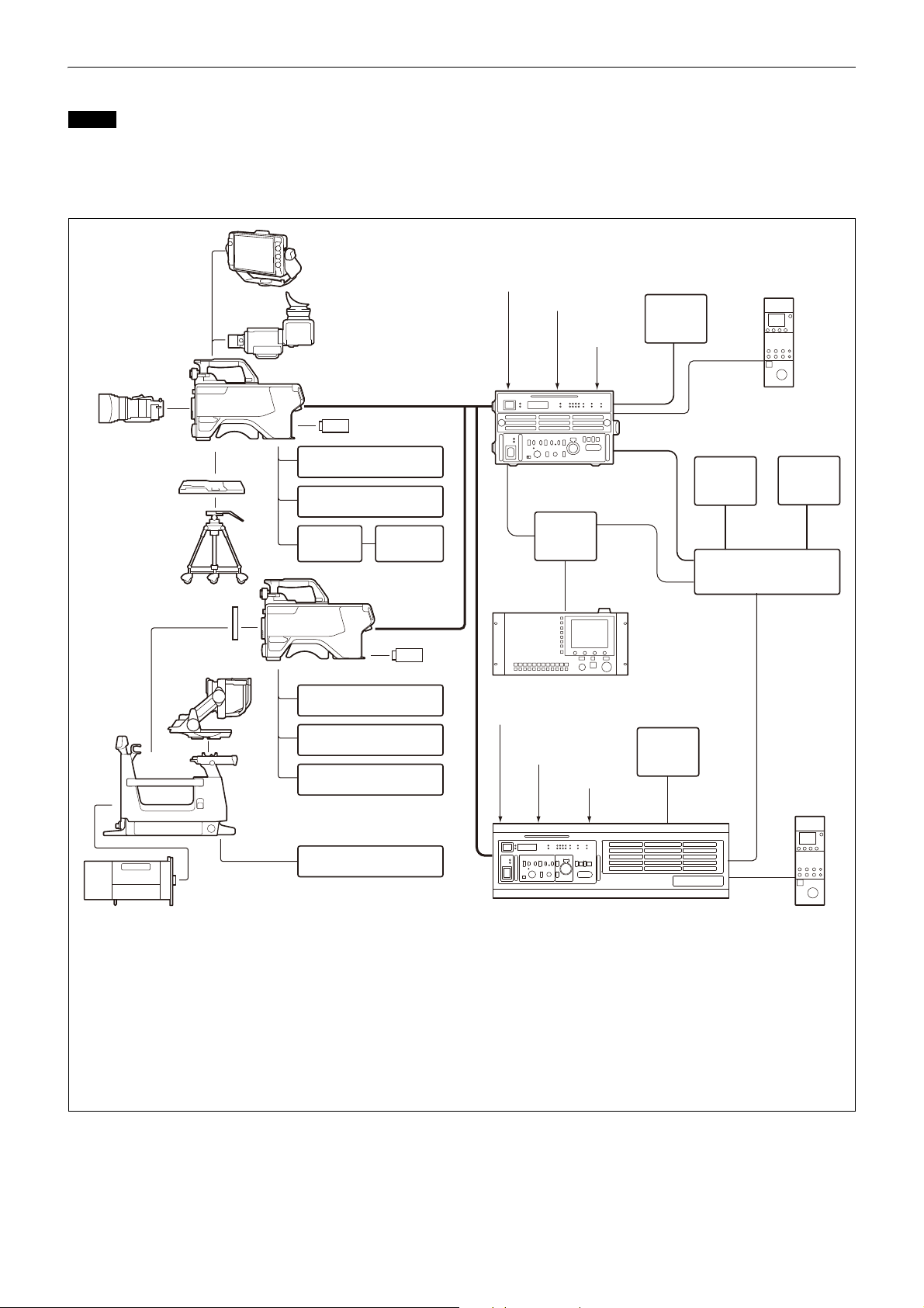
System Configuration
Lens
(for ENG/EFP)
VCT-14 Tripod
Attachment
Tripo d
USB drive
Camera hanger
a)
HDVF-EL70
Viewfinder
CAC-6 Return Video
Selector
Intercom headset
Microphone
HDLA1500-series Large
Lens Adaptor
BKP-7911 Script Holder
Lens
(for studio camera use)
HDVF-EL75/L750/L770
Viewfinder
HDC5500
HDC3500
b)
Optical fiber cable
c)
CAC-6 Return Video
Selector
Intercom headset
CAC-12
Microphone
Holder
Microphone
HDC5500
HDC3500
b)
HDVF-EL20
HDVF-EL30
Viewfinder
MSU-1000 series
Master Setup Unit
a) Supplied with HDLA1500 series (Part No.: A-1128-405-A)
b) Installation of the HKC-FB50 Fiber Transmission Adaptor and HKC-CN50 Side Panel Attachment Kit is required.
c) Signal transfer up to a maximum of 4 km is possible when using the HDCU5000, or 2 km when using the HDCU5500.
However, the actual transfer distance may vary depending on the system configuration of the cameras, the type of
optical fiber cables used, and the shooting format.
d) Configure the following menu items on the camera control unit according to the connected camera.
SYSTEM CONFIG t <CAMERA I/F> t CABLE TYPE t FIBER CAMERA CABLE
SYSTEM CONFIG t <CAMERA I/F> t FIBER TRANSMIT RATE t ULTRA
For details, refer to the operation manual of the camera control unit.
USB drive
RCP-3000/1000
series
Remote Control Panel
Sync signal input
Return video input
Intercom
microphone
input
4K video
monitor
CCA-5
Video
monitor
Waveform
monitor
BNC
HDCU5500
Camera Control Unit
d)
Video router
Hub
BNC
LAN cable
LAN
cable
LAN
cable
Sync signal input
Return video input
Intercom
microphone
input
BNC
BNC
4K video
monitor
HDCU5000
Camera Control Unit
RCP-3000/1000 series
Remote Control Panel
CCA-5
Note
Production of some of the peripherals and related devices shown in the figures has been discontinued. For advice on
choosing devices, please contact your Sony dealer or a Sony sales representative.
Connection example (4K optical fiber transmission)
5
Page 6
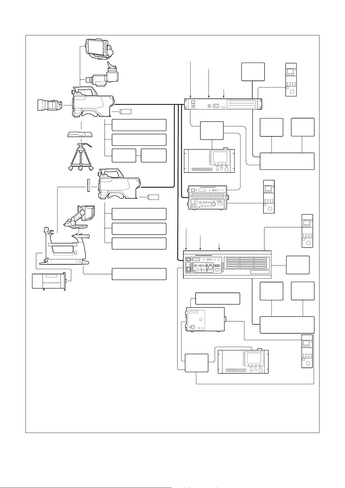
Connection example (HD optical fiber transmission)
Lens
(for ENG/EFP)
VCT-14 Tripod
Attachment
Tripod
USB drive
Camera hangers
a)
HDVF-EL70
Viewfinder
CAC-6
Return Video Selector
Intercom headset
Microphone
HDLA1500-series
Large Lens Adaptor
BKP-7911
Script Holder
Lens
(for stud io ca mera use)
HDVF-EL75/L750/L770
Viewfinder
HDC3500
Optical fiber cable
b)
CAC-6
Return Video Selector
Intercom headset
CAC-12
Microphone
Holder
Microphone
HDC3500
HDVF-EL20
HDVF-EL30
Viewfinder
BNC
HDCU3100
e)
, HDCU3170
d) e)
Camera Control Unit
c)
a) Supplied with HDLA1500 series (Part No.: A-1128-405-A)
b) Signal transfer up to a maximum of 4 km is possible when using
the HDCU5000/2000, or 2 km when using the HDCU3500/3100/
3170/2500. However, the actual transfer distance may vary
depending on the system configuration of the cameras, the type
of optical fiber cables used, and the shooting format.
c) Configure the following menu items on the camera control unit
according to the connected camera.
SYSTEM CONFIG t <CAMERA I/F> t CABLE TYPE t
FIBER CAMERA CABLE
SYSTEM CONFIG t <CAMERA I/F> t FIBER TRANSMIT RATE t
HIGH
For details, refer to the operation manual of the camera control
unit.
d) To use the HDCU3170, install the HKCU-FB30 Optical Fiber
Connector Kit.
e) Use software version 2.00 or later.
f) Use software version 3.30 or later.
g) The diagram shows the HDCU2500.
USB drive
RCP-3000/1000 series
Remote Control Panel
MSU-1000 series
Master Setup Unit
Sync signal input
Return video input
Intercom
microphone
input
Video
monitor
Waveform
monitor
Video router
2K video
monitor
BNC
CCA-5
Hub
Hub
HDCU5000
Camera Control Unit
HDCU2000/2500
f) g)
Camera Control Unit
RCP-3000/1000
series
Remote Control
Panel
Video
monitor
Waveform
monitor
Video router
CCA-5
LAN cable
RCP-3000/
1000 series
Remote
Control
Panel
CCA-5
BNC
HKCU1001/1003/
2007/2040
LAN cable
MSU-1000 series
Master Setup Unit
LAN cable
LAN cable
HDCU3500
Camera Control Unit
CCA-5
RCP-3000/1000
series
Remote Control
Panel
LAN cable
Sync signal input
Return video input
Intercom microphone input
4K video
monitor
BNC
LAN cable
LAN cable
6
Page 7
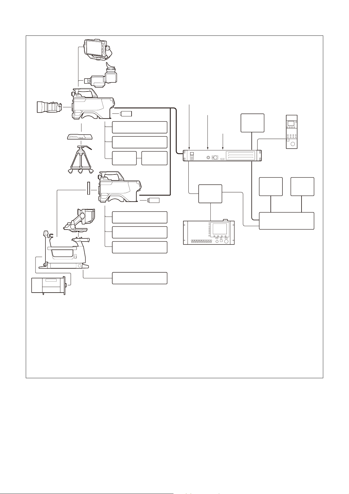
Connection example (digital triax transmission)
Lens
(for ENG/EFP)
VCT-14 Tripod
Attachment
Tripod
USB drive
Camera hangers
a)
HDVF-EL70
Viewfinder
CAC-6 Return Video
Selector
Intercom headset
Microphone
HDLA1500-series
Large Lens Adaptor
BKP-7911
Script Holder
Lens
(for studio camera use)
HDVF-EL75/L750/L770
Viewfinder
HDC3500
b)
Triax cable
c)
CAC-6 Return Video
Selector
Intercom headset
CAC-12
Microphone
Holder
Microphone
HDC3500
b) d)
HDVF-EL20
HDVF-EL30
Viewfinder
MSU-1000 series
Master Setup Unit
a) Supplied with HDLA1500 series (Part No.: A-1128-405-A)
b) Attach the HKC-TR37 Triax Transmission Adaptor and HKC-CN50 Side Panel Attachment Kit.
c) Signal transfer up to a maximum of 1.8 km is possible. However, the actual transfer distance may vary depending on the
system configuration of the cameras, the type of optical fiber cables used, and the shooting format.
For details, see
page 94
.
d) When using the HDLA1500 series, external DC power supply is not available.
e) Configure the following menu item on the camera control unit.
SYSTEM CONFIG t <CAMERA I/F> t CABLE TYPE t TRIAX CABLE
For details, refer to the operation manual of the camera control unit.
USB drive
RCP-3000/1000 series
Remote Control Panel
Sync signal input
Return video input
Intercom
microphone
input
2K video
monitor
CCA-5
Video
monitor
Waveform
monitor
BNC
HDCU3170
e)
Camera Control Unit
Video router
Hub
LAN cable
LAN
cable
BNC
7
Page 8
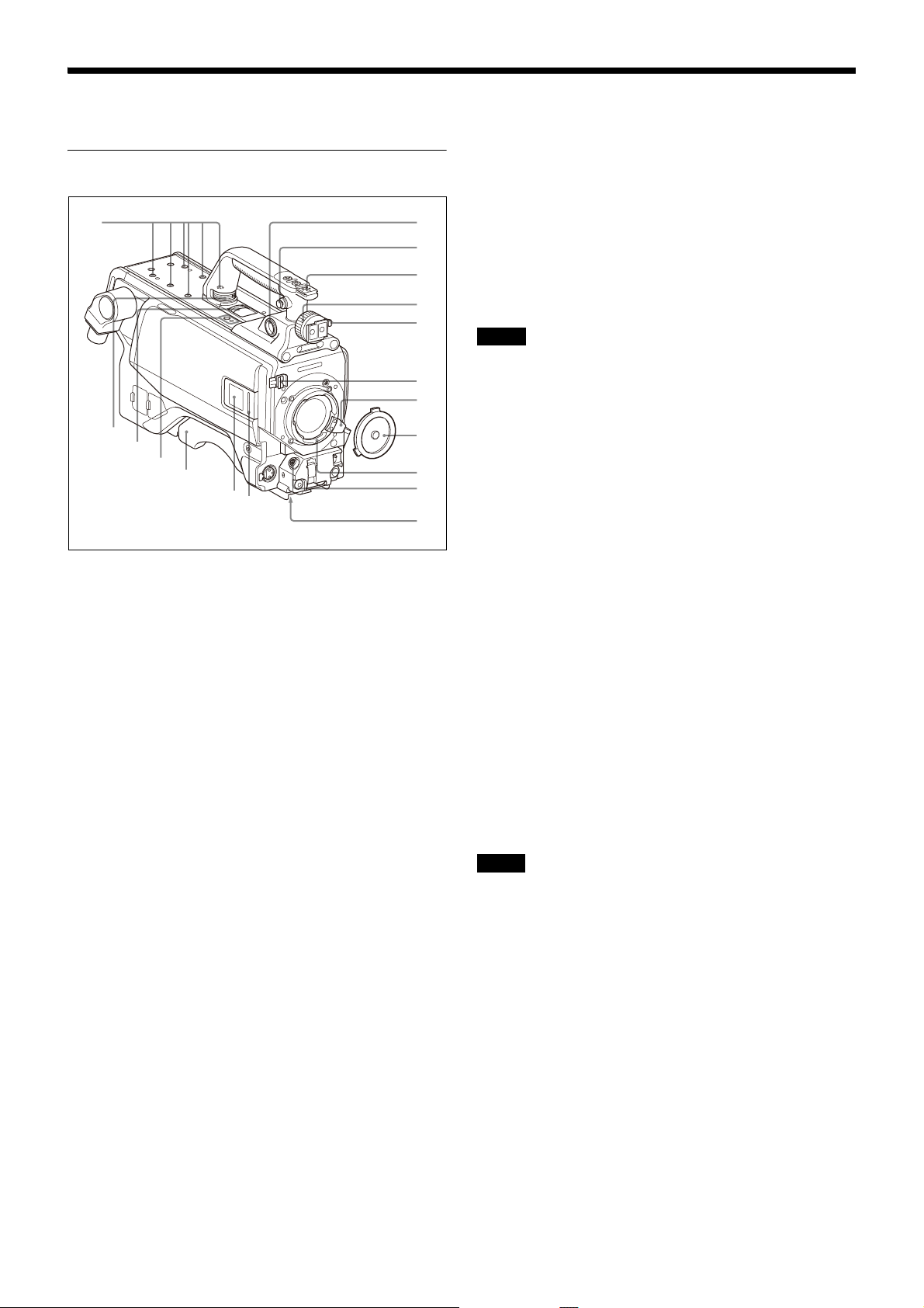
Locations and Functions of Parts
a
b
c
d
e
f
g
h
i
j
k
m
l
n
o
p
q
r
Accessory Attachments
a VF (viewfinder) connector (20-pin)
Connect the cable of the viewfinder (not supplied).
b Shoulder strap fitting post
Attach one end of a shoulder strap (not supplied) to this
fitting post, and the other end to the fitting post on the
other side of the camera.
k Tripod mount
Attach the VCT-14 Tripod Attachment when mounting the
camera on a tripod.
l LED lamp
Use as a tally. You can switch the function using the menu.
m Camera number
The unit uses electronic paper (e-ink) type camera
numbers. You can set the camera number using the menu.
Note
The operating temperature range of the camera number
setting is 0 °C to 45 °C (32 °F to 113 °F). The setting may not
be configurable if the temperature range is exceeded.
Check the temperature when configuring.
n Shoulder pad
You can adjust the position so that you can get the best
balance for shooting with the camera on your shoulder.
For details, see “Adjusting the Shoulder Pad Position” on
page 18.
o Microphone holder attachment
Use to attach a CAC-12 Microphone Holder.
For details, refer to the microphone holder operation
manual.
p Handle rotation release lever
Push the lever toward the rear with the handle rotation lock
knob in the loosened state to enable rotation of the handle.
c Accessory shoe
To attach an accessory using a 1/4-inch screw.
d Viewfinder left-right positioning ring
Loosen this ring to adjust the viewfinder position towards
the left or right.
e Viewfinder front-rear positioning lever
Unlock the front-rear positioning lever to adjust the
viewfinder position towards the front or rear, then lock in
the desired position.
For details on adjusting the viewfinder position, see
“Attaching an Eyepiece Viewfinder” on page 15.
f Lens cable clamp
To secure the cable of the lens (not supplied).
g Lens fixing lever
To secure the lens in the lens mount.
h Lens mount cap
The cover can be removed by moving the lens fixing lever
upwards. Always keep the lens mount covered with this cap
when a lens is not attached.
i Lens mount
To attach a lens.
j LENS connector (12-pin)
Connect the lens cable. The camera can control the lens
functions through this cable.
q Handle rotation lock knob
Turn counterclockwise until loosened to unlock the handle.
Rotate the handle to reduce the interference with the
viewfinder and to enable wide angle adjustment of the tilt
and pan of the viewfinder.
r V-wedge shoe attachment points
Attach a V-wedge shoe here to mount an HDVF-EL75/L750/
L770 Viewfinder.
Note
Select either the front or rear V-wedge shoe attachment
points to attach the V-wedge shoe. If the front position is
used, it may restrict the tilt/pan angle available for the
viewfinder.
For details about attachment, refer to the operation manual
of the viewfinder.
8
Page 9
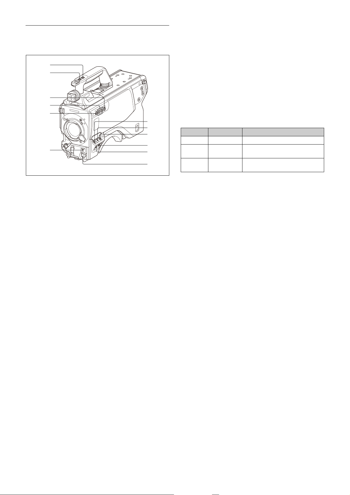
Controls and Connectors
a
b
c
d
e
f
g
h
i
j
k
l
Front right
g GAIN switch
To select the gain of the video amplifier based on lighting
conditions when the camera is used in standalone status
without connecting a camera control unit.
When shipped from the factory, the values set are L = 0 dB,
M = 6 dB, and H = 12 dB.
h OUTPUT (output signal selection)/AUTO KNEE switch
To select the signal (color bar signal or camera’s video
signal) to be used as output to the viewfinder or a video
monitor when the camera is used in standalone status
without connecting a camera control unit.
When the camera’s video signal is being used as output,
the auto knee function may be used.
The relationship between the switch setting and the output
signal and auto knee function is shown in the table below.
OUTPUT AUTO KNEE Function
BARS OFF Output is a color bar signal.
CAM OFF Output is the camera’s video signal.
The auto knee circuit is disabled.
CAM ON Output is the camera’s video signal.
The auto knee circuit is enabled.
a INCOM1 (intercom 1) button
The intercom 1 microphone is turned ON while this button
is held pressed.
You can also assign other functions to this button, using the
menu displayed on the viewfinder screen.
b RET 1 (return video 1) button
The return video 1 signal from the camera control unit is
monitored on the viewfinder screen while this button is
pressed. It functions the same as the RET 1 button on the
page 10
side (
operation panel on the rear of the camera (
) and RET/ASSIGNABLE button A on the
page 11
or 12).
You can also assign other functions to this button, using the
menu displayed on the viewfinder screen.
c Assignable switch
You can assign a function using the menu displayed on the
viewfinder screen.
You can also display the assigned function name by
attaching the corresponding label (supplied) for the
assigned function.
d Filter select buttons
You can switch the built-in ND and CC (color temperature
conversion) filters by pressing the selectors while holding
the FILTER LOCAL button depressed.
Pressing the left button selects the available ND filters
(CLEAR, 1/4ND, 1/8ND, 1/16ND,1/64ND) in sequence.
Pressing the right button selects the available CC filters
(cross, 3200K, 4300K, 6300K) in sequence.
e FILTER LOCAL button
While holding this button depressed, press either of the
filter select buttons to select the built-in optical filters.
f AUTO W/B BAL (white and black balance automatic
adjustment) switch
To automatically adjust white and black balance when the
camera is used in standalone status without connecting to
the camera control unit.
WHT: Automatically adjust white balance.
BLK: Automatically adjust black balance.
i WHITE BAL (white balance memory selection) switch
To select the white balance adjustment method or the
memory used to store the adjusted value when the camera
is used in standalone status without connecting a camera
control unit.
PRST (preset memory): White balance is adjusted to a
preset value corresponding to a color temperature of
3200K.
A or B: Selects memory A or B.
j DISPLAY switch
The functions of the DISPLAY switch are as follows:
DISPLAY: Characters and messages showing the camera
settings and operating status may be displayed on the
viewfinder screen.
OFF: Status messages will not appear on the viewfinder
screen.
MENU: Menus for camera settings will be displayed on the
viewfinder screen.
k STATUS/CANCEL switch
STATUS: When no menu is displayed on the viewfinder
screen, the status information of this camera is
displayed.
CANCEL: When a menu is displayed on the viewfinder
screen, you can cancel any changed settings or return
the display to the previous menu.
l MENU SEL (menu select) knob/ENTER button (rotary
encoder)
To select settings from menus displayed on the viewfinder
screen (by rotating the knob) and to confirm settings (by
pushing the button).
You can change the ECS frequency by pushing the ENTER
button when no menu is displayed on the viewfinder
screen. Make sure that the camera is used in standalone
status without connecting a camera control unit, and the
shutter mode is set to ECS. When the camera is used in
standalone status and the shutter mode is set to other than
ECS, the VF DETAIL function can be adjusted.
9
Page 10
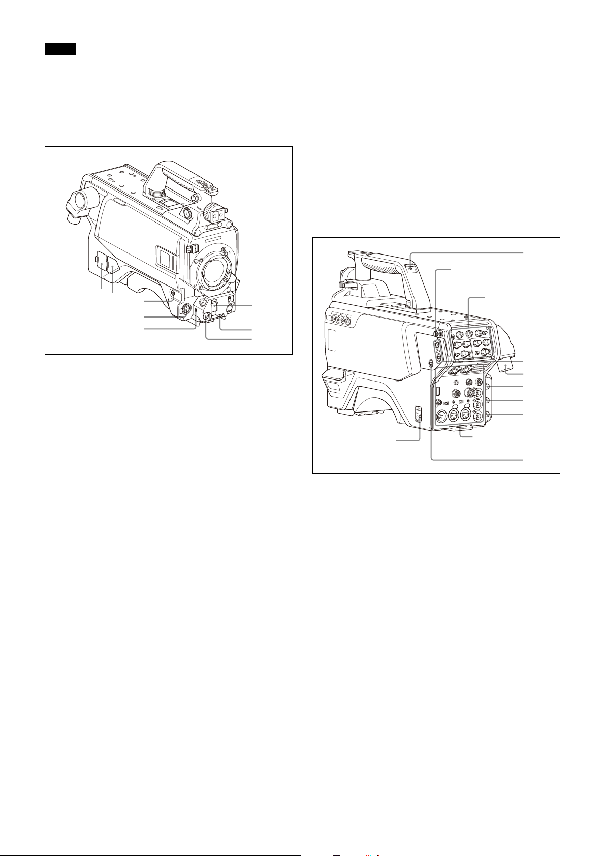
Note
a
b
c
d
e
g
f
h
b
c
d
e
f
g
h
a
Operation
panel (
page 11
)
Shoulder strap fitting
post (
page 8
)
Connector panel
(
page 12
)
When a camera control unit or a remote control device,
such as an MSU or RCP-series Remote Control Panel, is
connected, the functions of 6 to 9 are controlled from the
external control device and the controls on the camera are
disabled.
g INTERCOM LEVEL control
To adjust the intercom/earphone volume level.
The intercom level adjustment is enabled when the
INTERCOM 1 and 2 LEVEL/MIC switches (on the UCJ model
operation panel,
page 11
switch (on the CE model operation panel,
) are set to “FRONT” or the LEVEL
page 12
) on the
rear of the camera is set to “FRT.”
Front left
a NETWORK TRUNK connector (RJ-45 8-pin)
Connects a device connected to the CCU’s NETWORK
TRUNK connector to the network.
b DC power supply out connector (2-pin)
Supplies power to an external device up to 2.5 A.
h RET 2 (return video 2) button
When this button is pressed, the picture on the viewfinder
screen changes to the return video signal selected using
RET/ASSIGNABLE button A, B, or C on the operation panel
on the rear of the camera or using the menu.
You can also assign other functions to this button, using the
menu displayed on the viewfinder screen.
Rear
c RET 1 (return video 1) button
The return video 1 signal from the camera control unit is
monitored on the viewfinder screen while this button is
pressed. It function the same as the RET 1 button on the
handle (
operation panel on the rear of the camera (
page 9
) and RET/ASSIGNABLE button A on the
page 11
or 12).
You can also assign other functions to this button, using the
menu displayed on the viewfinder screen.
d MIC 1 IN (microphone 1 input) connector (XLR 3-pin)
Connect a microphone.
This connector and the AUDIO IN CH-1 connector (
page 13
on the operation panel on the rear of the camera are
alternately activated with the CH1 audio input select switch
page 13
(
).
e MIC (microphone) power switch
+48V: To supply power at +48 V to the connected
microphone.
OFF: Not to supply power to the connected microphone.
f SHUTTER switch
For setting the electronic shutter functions when the
camera is used in standalone status without connecting a
camera control unit.
OFF: The electronic shutter does not function.
ON: The electronic shutter is activated.
SEL: The shutter speed and shutter mode change each time
the switch is set to this position.
For details, see “Setting the Electronic Shutter” on page 22.
a CAMERA POWER switch
CCU: Power is supplied from the camera control unit.
EXT: Power is supplied through the DC IN connector.
b Tally lamp and switch
ON: The tally lamp lights when a tally signal is input to the
)
connected camera control unit or a call signal is
generated in response to pressing of a CALL button.
OFF: The tally lamp is prevented from lighting.
c RET 1/2 (return video 1/2) buttons
When pressed, the picture on the viewfinder screen changes
to the return video signal selected using the operation panel
on the rear of the camera or using the menu.
You can also assign other functions to this button, using the
menu displayed on the viewfinder screen.
d CCU (camera control unit) connector
Connect a camera control unit using an optical/electrical
multi cable.
e SDI 1 (serial digital interface 1) connector (BNC-type)
HDC5500: For HD-SDI signal, 3G-SDI signal, 6G-SDI signal,
12G-SDI signal, and UHD PROMPTER signal output.
HDC3500: For 3G-SDI, HD-SDI, or HD PROMPTER signal
output.
For details on the output signals, see “Setting the Camera
Outputs” (page 26).
10
Page 11
f SDI 2 (serial digital interface 2) connector (BNC-type)
PGM1 control
PGM2 control
INCOM level control
Line select / Receive
MIX select switch
LEVEL/MIC switch
HDC5500: For HD-SDI signal, 3G-SDI signal, 6G-SDI signal,
and 12G-SDI signal output. Also for HD TRUNK signal
and UHD TRUNK signal input.
HDC3500: For 3G-SDI and HD-SDI signal output, or HD
TRUNK signal input.
During stand-alone operation, also used for inputting an
HD-SDI return signal.
When RET (return) is set to 1, this is displayed in the
viewfinder.
g SDI 3 connector (BNC-type) (HDC5500)
For HD PROMPTER signal output.
g PROMPTER2 connector (BNC-type) (HDC3500)
For prompter 2 signal output. Available only when
connecting a camera control unit with a prompter 2 input
connector.
h CALL button
When this button is pressed, the red tally lamp of the
RCP-3000/1000 series Remote Control Panel or the
MSU-1500/1000 series Master Setup Unit will light. Use to
call the operator of the RCP or MSU.
You can also assign other functions to this button, using the
menu displayed on the viewfinder screen.
Operation panel
UCJ model: For USA, Canada, East Asia and other
countries
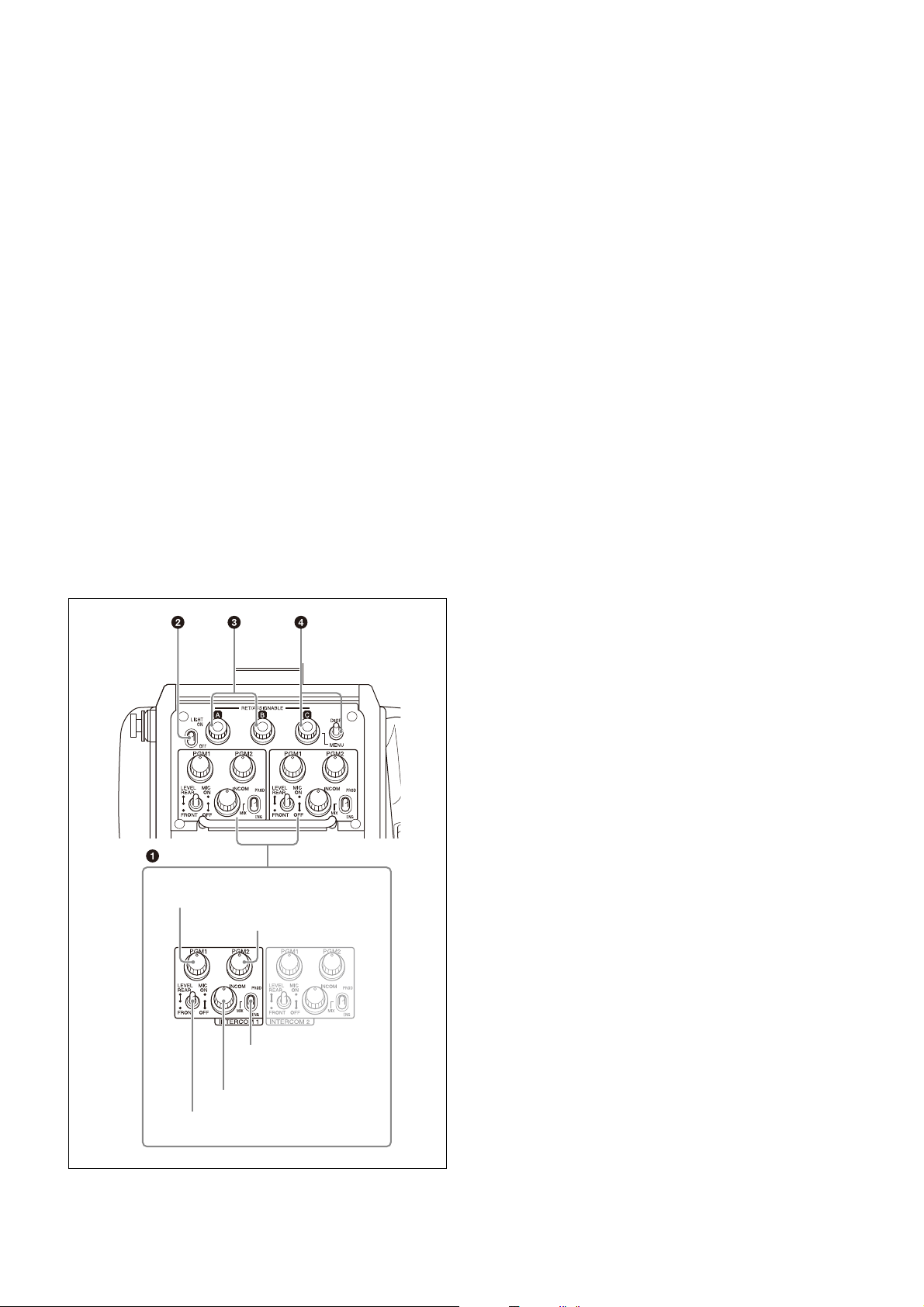
a INTERCOM 1 and INTERCOM 2 controls and switches
There are separate PGM1 and PGM2 controls, line select/
receive MIX select switch, LEVEL/MIC switch, and INCOM
level control for both intercom line 1 and intercom line 2.
PGM1 (program 1) control
Adjust the audio listening level of program 1, and program
3 (when PGM3 VOLUME LINK is set to PGM1).
PGM2 (program 2) control
Adjust the audio listening level of program 2, and program
3 (when PGM3 VOLUME LINK is set to PGM2).
LEVEL/MIC switch
REAR/ON: The intercom headset microphone is turned
on. The intercom audio listening level is adjusted
with the INCOM level control.
REAR/OFF: The intercom headset microphone is
turned off. The intercom audio listening level is
adjusted with the INCOM level control.
FRONT/OFF: The intercom headset microphone is
turned off. The intercom audio listening level is
adjusted with the INCOM level control and the
INTERCOM LEVEL control on the front of the
camera
(page 10)
.
INCOM level control
Adjust the intercom audio listening level. The intercom MIX
TALK (ENG or PROD), SIDE TONE, and TRACKER settings are
reflected in the intercom audio.
Line select / Receive MIX select switch
Select the intercom line.
PROD: Producer line
ENG: Engineer line
MIX: Receive mixed PROD/ENG audio. Select the
intercom talk line from the menu.
The default intercom line setting is ENG.
b LIGHT switch
Set to ON to illuminate the operation panel.
c RET/ASSIGNABLE button A, B
Press the button to switch the function assigned to the
button on the <REAR FUNCTION ASSIGN> page on/off.
When the return function is assigned, press the button to
display the return video signal on the viewfinder screen
while the button is pressed.
Turn the button to change the assigned function setting.
When the return function is assigned, you can change the
return signal channel.
d RET/ASSIGNABLE button C / DISP/MENU switch
Press the button to switch the function assigned to the
button on the <REAR FUNCTION ASSIGN> page on/off.
When the return function is assigned, press the button to
display the return video signal on the viewfinder screen
while the button is pressed.
Turn the button to change the assigned function setting.
When the return function is assigned, you can change the
return signal channel.
When the DISP/MENU switch is set to the MENU position to
display the MENU screen, you can perform menu
operations using RET/ASSIGNABLE button C.
11
Page 12
CE model: For Europe and South Asia
PGM1
control
PGM2 control
TRACKER
control
LEVEL switch
MIC LINE1
switch
ENG
control
PROD control
MIC LINE2
switch
PROMPTER
TEST
OUT
LINE
+48V
OFF
MIC
SDI
MONI
AUDIO IN
CH1 CH2
/GEN
LOCK
LINE
+48V
OFF
FRONT MIC
MIC
EARPHONE
RET CTRL
DC IN 10.5-17V
DC OUT
CRANE
TRACKER
REMOTE
AES/EBU
a
b
c
d
e
f
g
h
i
j
k
l
m
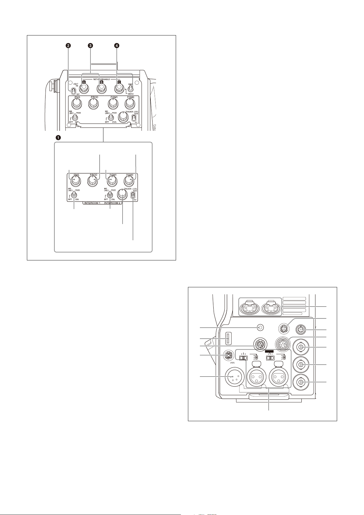
a INTERCOM 1 and INTERCOM 2 controls and switches
The reception level controls are common to intercom 1 and
intercom 2. The talk lines can be set independently for
intercom 1 and intercom 2.
TRACKER control
Adjust the intercom audio listening level at the TRACKER
connector (
page 13
) on the connector panel when using the
connector for intercom.
LEVEL switch
REAR: The intercom audio listening level is adjusted
with the controls on this panel.
FRT: The intercom audio listening level is adjusted with
the INTERCOM LEVEL control on the front of the
camera.
b LIGHT switch
Set to ON to illuminate the operation panel.
c RET/ASSIGNABLE button A, B
Press the button to switch the function assigned to the
button on the <ROTARY ENCODER ASSIGN> page on/off.
When the return function is assigned, press the button to
display the return video signal on the viewfinder screen
while the button is pressed.
Turn the button to change the assigned function setting.
When the return function is assigned, you can change the
return signal channel.
d RET/ASSIGNABLE button C / DISP/MENU switch
Press the button to switch the function assigned to the
button on the <ROTARY ENCODER ASSIGN> page on/off.
When the return function is assigned, press the button to
display the return video signal on the viewfinder screen
while the button is pressed.
Turn the button to change the assigned function setting.
When the return function is assigned, you can change the
return signal channel.
When the DISP/MENU switch is set to the MENU position to
display the MENU screen, you can perform menu
operations using RET/ASSIGNABLE button C.
Connector panel
ENG (engineer line) control
Adjust the intercom audio listening level of the engineer
line.
PROD (producer line) control
Adjust the intercom audio listening level of the producer
line.
PGM1 (program 1) control
Adjust the audio listening level of program 1, and program
3 (when PGM3 VOLUME LINK is set to PGM1).
PGM2 (program 2) control
Adjust the audio listening level of program 2, and program
3 (when PGM3 VOLUME LINK is set to PGM2).
MIC LINE1 (intercom microphone line 1) switch
Select the talk line for intercom 1.
PROD: To talk over the producer line
OFF: To turn off the headset microphone for intercom
ENG: To talk over the engineer line
MIC LINE2 (intercom microphone line 2) switch
Select the talk line for intercom 2.
PROD: To talk over the producer line
OFF: To turn off the headset microphone for intercom
ENG: To talk over the engineer line
line 1.
line 2.
a EARPHONE jack (4-pole mini jack)
Connect to a headset, or earphones with microphone (3pole/4-pole earphones), to input/output the intercom
audio signal.
For 4-pole earphones, the intercom line is linked to the
OPERATION LINK setting on the <EARPHONE> page in the
OPERATION menu.
12
Page 13
LINE
+48V
OFF
MIC
AUDIO IN
CH1 CH2
LINE
+48V
OFF
FRONT MIC
MIC
AES/EBU
CH2 audio input select switch
CH1 audio input select switch
Microphone power switches
AUDIO IN CH1 connector AUDIO IN CH2 connector
Turn the microphone function on/off using HEADSET MIC
(page 49)
in the OPERATION menu. The default setting is
OFF.
b USB connector (for connecting a USB drive)
Connect a USB drive to save or load the settings data file.
For details, see “Using a USB drive” (page 96).
c TRACKER connector (12-pin)
For external interface, such as intercom and tally.
d RET CTRL (return control) connector (6-pin)
For connection to a CAC-6 Return Video Selector.
e DC IN (DC power supply input) connector (XLR 4-pin)
Used for connection to the AC-DN10A AC Adaptor to supply
power to the camera.
f INTERCOM1 and 2 (intercom 1 and 2) connectors (XLR
5-pin)
Used for input and output of intercom audio signals if an
XLR 5-pin headset is connected.
The INTERCOM 1 connector can be used for communication
over the engineer line even when the power is off, as long
as the power LED is lit in red.
g DC OUT (DC power supply output) connector (4-pin)
To supply power to devices such as a wireless receiver
(optional) (max. 0.5 A).
h REMOTE connector (8-pin)
For connection to an RCP-3000/1000 series Remote Control
Panel, or MSU-1000/1500 Master Setup Unit.
Note
When the camera is connected to a CCU, do not connect
any remote control device, such as RCP and MSU, to this
connector.
i CRANE connector (12-pin)
For external interface, such as viewfinder and external data.
j PROMPTER/GENLOCK (prompter 1 signal output/
external gen-lock signal input) connector (BNC-type)
The PROMPTER OUT function is enabled when a camera
control unit is connected. The GENLOCK IN function is
enabled when a camera control unit is not connected.
GENLOCK IN: For input of an external gen-lock signal (VBS
or 3-level sync) during stand-alone operation.
PROMPTER: For output of the prompter 1 signal (valid only
when a camera control unit is connected). When a
camera control unit having two prompter inputs is
connected, the signal of input 1 is output from this
connector.
k TEST OUT connector (BNC-type)
To output the analog signal.
This can also output a VBS signal, HD-SYNC signal, or
SD-SYNC signal, whichever is selected in the menu.
For details on the output signals, see “Setting the Camera
Outputs” (page 26).
l SDI MONI (serial digital interface) connector (BNC-
type)
For HD-SDI or SD-SDI signal output.
For details on the output signals, see “Setting the Camera
Outputs” (page 26).
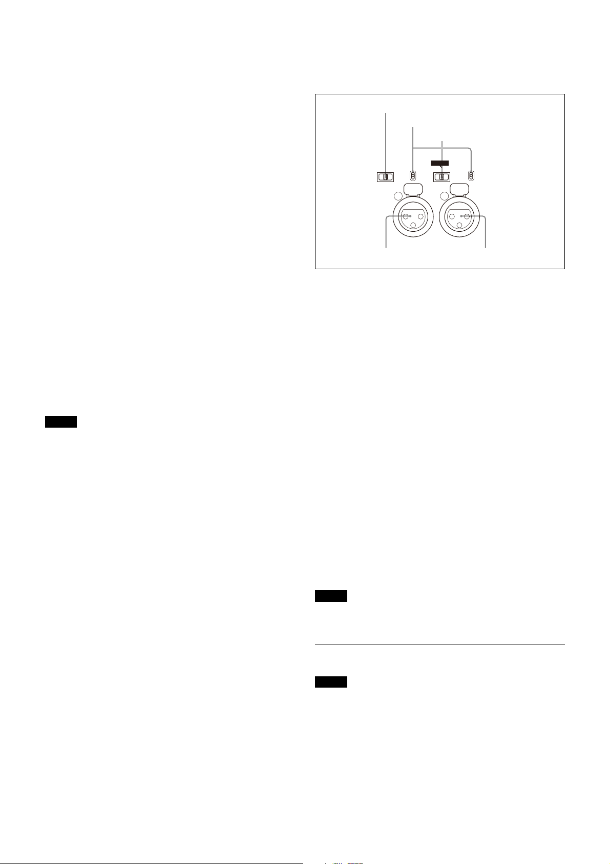
m AUDIO IN CH1 and CH2 connectors (XLR 3-pin) and
switches
Connect audio signals. An input select switch and
microphone power switch are provided for each channel.
CH1 audio input select switch
Set to the appropriate position according to the equipment
connected to the AUDIO IN CH1 connector.
LINE: When a line-level (0 dBu) signal source is
connected
FRONT MIC: When using the microphone connected to
the MIC 1 IN connector
MIC: When an external microphone is connected
CH2 audio input select switch
Set to the appropriate position according to the equipment
connected to the AUDIO IN CH2 connector.
LINE: When a line-level (0 dBu) signal source is
connected
AES/EBU: When a digital audio signal is connected
(The signal must be in synchronization with the
camera output).
MIC: When an external microphone is connected
Microphone power switches
When a microphone is connected to the corresponding
AUDIO IN connector, set whether or not to supply power to
the microphone.
+48V: To supply power at +48 V
OFF: Not to supply power
(No function has been assigned to the lowermost
position. No power is supplied to the microphone.)
Note
To supply +12 V power, contact a Sony sales representative
or Sony service representative.
Transmission Adaptor Options
Note
For safety, only a qualified technician with service training
should perform tasks inside the unit.
For details about installation, contact a Sony service or sales
representative.
HKC-FB50 UHB Fiber Transmission Adaptor
The name and function of the connectors used are
described below.
13
Page 14
NETWORK TRUNK connector (RJ-45 8-pin) (see item 1 of
front left side
connected to the CCU’s NETWORK TRUNK connector to
the network.
CCU (camera control unit) connector (see item 4 of rear
side
(page 10)
electrical multi cable.
SDI 1 (serial digital interface 1) connector (BNC-type) (see
item 5 of rear side
SDI signal, 6G-SDI signal, 12G-SDI signal, and UHD
PROMPTER signal output.
SDI 2 (serial digital interface 2) connector (BNC-type) (see
item 6 of rear side
SDI signal, 6G-SDI signal, and 12G SDI signal output, or
HD TRUNK and UHD TRUNK signal input.
During standalone operation, input the HD-SDI return
signal.
When RET (return) is set to 1, the return signal is
displayed in the viewfinder.
SDI 3 (serial digital interface 3) connector (BNC-type) (see
item 7 of rear side
signal output.
(page 10)
): Connect a CCU using an optical/
): Connects a device
(page 10)
(page 10)
(page 10)
): For HD-SDI signal, 3G-
): For HD-SDI signal, 3G-
): For HD prompter
HKC-FB30 Fiber Transmission Adaptor
The name and function of the connectors used are
described below.
NETWORK TRUNK connector (RJ-45 8-pin) (see item 1 of
front left side
connected to the CCU’s NETWORK TRUNK connector to
the network.
CCU (camera control unit) connector (see item 4 of rear
side
(page 10)
electrical multi cable.
SDI 1 (serial digital interface 1) connector (BNC-type) (see
item 5 of rear side
SDI signal, or HD PROMPTER signal output.
SDI 2 (serial digital interface 2) connector (BNC-type) (see
item 6 of rear side
SDI signal, or HD TRUNK signal input.
During standalone operation, input the HD-SDI return
signal.
When RET (return) is set to 1, the return signal is
displayed in the viewfinder.
PROMPTER2 (prompter 2) connector (BNC-type): For
prompter 2 signal output. Available only when
connecting a camera control unit with a prompter 2
input connector.
(page 10)
): Connect a CCU using an optical/
): Connects a device
(page 10)
(page 10)
): For 3G-SDI signal, HD-
): For 3G-SDI signal, HD-
HKC-TR37 Triax Transmission Adaptor
The name and function of the connectors used are
described below.
CCU (camera control unit) connector (see item 4 of rear
side
(page 10)
SDI 1 (serial digital interface 1) connector (BNC-type) (see
item 5 of rear side
HD-SDI signal output.
): Connect a CCU using a triax cable.
(page 10)
): For 3G-SDI signal or
Preparations
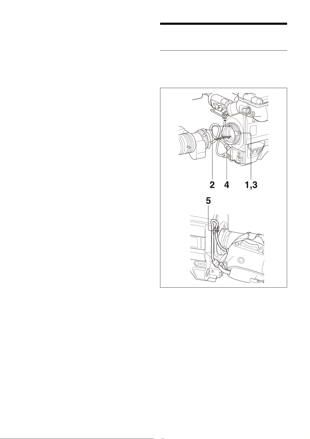
Attaching a Lens
For information on handling lenses, refer to the lens’
operation manual.
Attaching procedure
1 Push the lens fixing lever upwards and remove the
lens mount cap from the lens mount.
2 Align the lens’ alignment pin with the notch in the
upper part of the lens mount and insert the lens into
the mount.
3 While supporting the lens, push the lens fixing lever
downwards to secure the lens.
4 Connect the lens cable to the LENS connector.
HKC-WL50 Wireless Transmission Adaptor
Connects video signals and control signals to a third-party
wireless module to support wireless transmission.
For details about supported wireless modules, contact your
Sony sales representative.
5 Secure the lens cable with the cable clamp.
14
Page 15
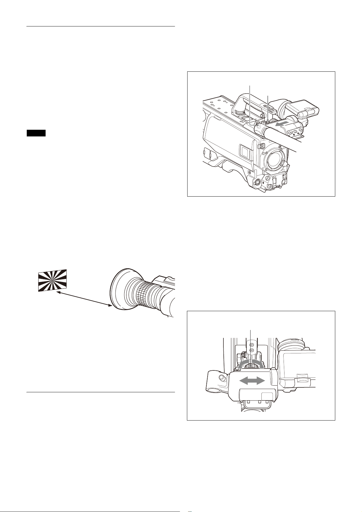
Adjusting the Flange Focal Length
About 3 meters (10 ft)
Viewfinder stopper
VF connector
Viewfinder left-right
positioning ring
Adjustment of the flange focal length (the distance
between the lens mount attachment plane and the imaging
plane) is necessary in the following situations:
• The first time a lens is attached
• When changing lenses
• If the focus is not sharp at both telephoto and wide angle
when zooming
The flange focal length can be more precisely adjusted by
using the focus assist indicators.
See “Displaying the focus assist indicators” on page 23 for
the focus assist indicators.
Note
The various parts of the lens used in adjusting the flange
focal length are in different positions on different lenses.
Refer to the operation manual for the particular lens.
Adjusting procedure
1 Set the iris control to manual, and open the iris fully.
2 Place a flange focal length adjustment chart
approximately 3 meters from the camera and adjust
the lighting to get an appropriate video output level.
3 Loosen the Ff (flange focal length) ring lock screw.
4 With either manual or power zoom, set the zoom
ring to telephoto.
Attaching a viewfinder
This section describes using a HDVF-20A/200/EL20/EL30
(the HDVF-EL30 is shown in the diagrams).
For details about the viewfinder, refer to the operation
manual of the viewfinder.
1
Slide the viewfinder in the direction of the arrow.
The viewfinder stopper automatically pops down.
2 Set the viewfinder left-right position, then tighten
the left-right positioning ring (see
position to the left or right”
below).
“To adjust the
5 Aim at the flange focal length adjustment chart and
turn the focus ring to focus the image.
6 Set the zoom ring to wide angle.
7 Turn the Ff ring to bring the chart into focus. Take
care not to move the distance ring.
8 Repeat steps 4 through 7 until the image is in focus
at both telephoto and wide angle.
9 Tighten the Ff ring lock screw.
Attaching an Eyepiece Viewfinder
Warning
When the viewfinder is attached, do not leave the camera
with the eyepiece facing the sun. Direct sunlight can enter
through the eyepiece, be focused in the viewfinder and
cause fire.
3 Connect the viewfinder cable to the VF connector of
the camera.
Adjusting the viewfinder position
The viewfinder position may be adjusted towards the front
and rear and to the left and right to make it easier to view.
To adjust the position to the left or right
1
Loosen the viewfinder left-right positioning ring.
2 Slide the viewfinder left or right to move it into a
good viewing position.
3 Tighten the viewfinder left-right positioning ring.
15
Page 16
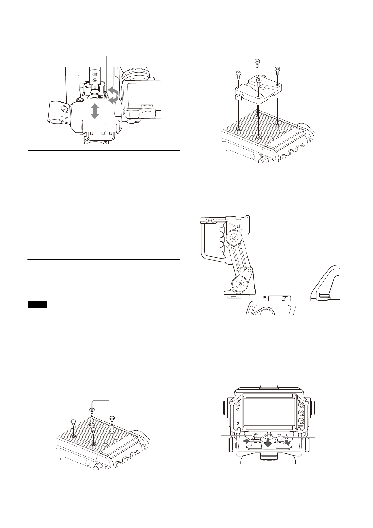
To adjust the position forward or backward
Viewfinder front-rear
positioning lever
Plastic caps
2
1
Lever
Button
1
Set the viewfinder front-rear positioning lever to the
unlocked position.
2 Attach the V-wedge shoe attachment to the camera
using the supplied hexagonal wrench and four
hexagonal screws (4×12).
2 Slide the viewfinder towards the front or rear of the
camera to move it into a good viewing position.
3 Set the viewfinder front-rear positioning lever to the
lock position to secure the viewfinder.
Detaching the viewfinder
Loosen the viewfinder left-right positioning ring, pull the
viewfinder stopper, then pull out the viewfinder by sliding
it in the direction opposite to that when attached.
Attaching an Electronic Viewfinder
Attach the V-wedge shoe attachment (supplied with the
viewfinder) to the camera and attach the viewfinder to the
attachment.
Notes
• When attaching the viewfinder to the camera or
removing it from the camera, be sure to lock the
viewfinder in its standard position.
• When removing the viewfinder from the camera, be sure
to secure the tripod with its tilt-lock mechanism and hold
the viewfinder firmly. Be careful not to fall or drop the
viewfinder and camera.
• When attaching the V-wedge shoe attachment, be sure
to use the supplied hexagonal screws.
3 Insert the viewfinder firmly into the V-wedge shoe
attachment.
There is an audible click when the viewfinder snaps into
the attachment.
4 Connect the camera connector of the viewfinder to
the VF connector of the camera.
Detaching the viewfinder
Pull the lever and push down the button while pulling the
viewfinder toward you, as shown in the figure below.
1
Remove the four plastic caps from the camera.
16
Page 17
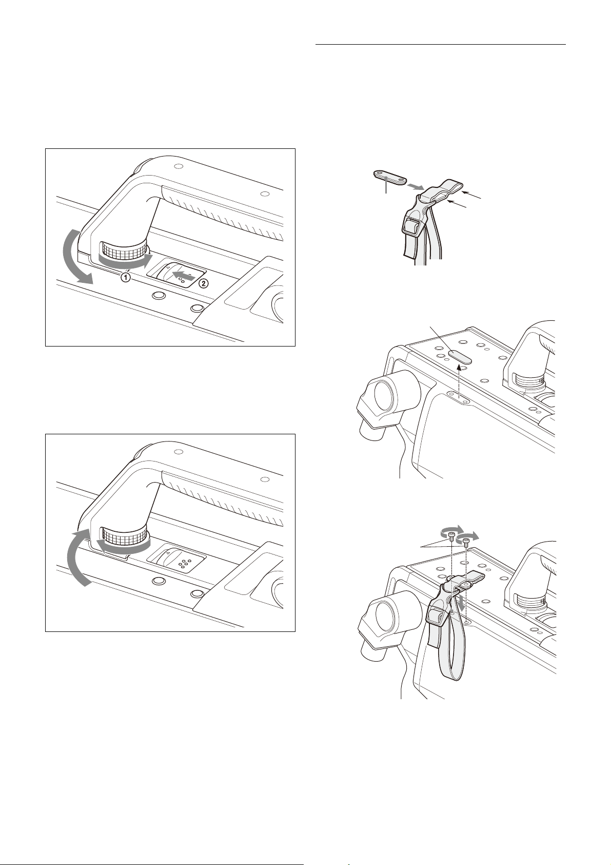
If the tilt/pan angle available for the
Belt bracket
Cover seal
+B3×8 screws
viewfinder is restricted
You can alleviate interference by rotating the camera
handle.
1
Loosen the handle rotation lock knob 1 of the
camera until it turns freely, then push the handle
rotation release lever 2 to unlock the grip.
Attaching the Cable Clamp Belt
(Supplied)
You can secure the optical/electrical multi cable or triax
cable, connected to the CCU connector, to the side of the
camera by attaching the supplied cable clamp belt.
1 Insert the belt bracket into hole A or B of the cable
clamp belt.
B
A
2 Peel off the cover seal from the camera as shown in
the following diagram.
2 Rotate the handle toward the front of the camera.
To stow the handle of the camera in the original
position
Return the handle to the lock position, and securely tighten
the handle rotation lock knob.
3 Secure the cable clamp belt to the camera, using the
two supplied +B3×8 screws.
17
Page 18
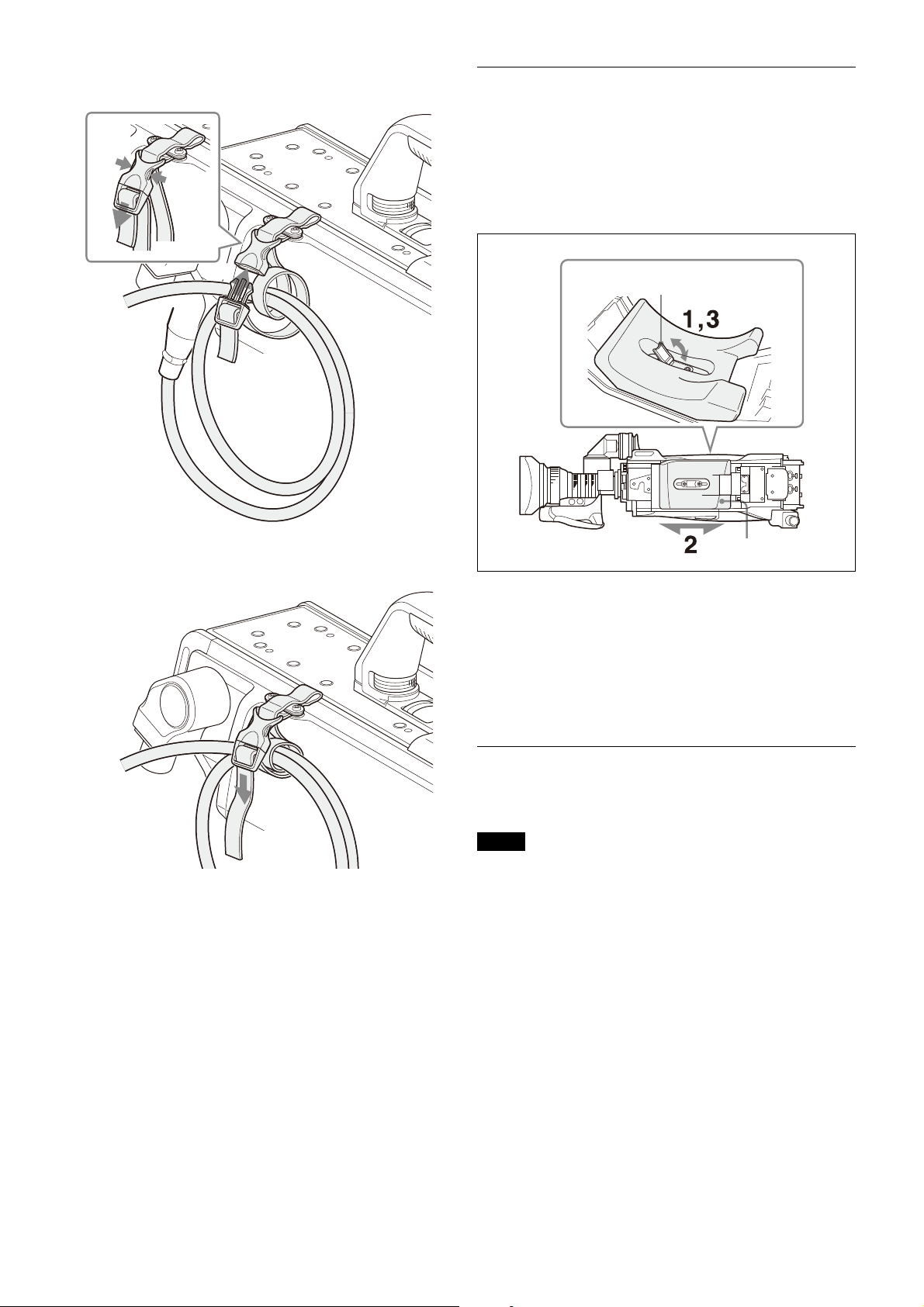
4 1 Release the buckle, 2 bundle the cable with the
1
2
3
Optical/
electrical multi
cable or triax
cable
Shoulder pad
Shoulder pad lock lever
Bottom of the camera
belt, 3 then lock the buckle again.
Adjusting the Shoulder Pad Position
You can shift the shoulder pad from its center position
(factory setting) backward by up to 10 mm (3/8 inch) or
forward by up to 25 mm (1 inch). This adjustment helps you
get the best balance for shooting with the camera on your
shoulder.
Adjusting procedure
5 Adjust the length by pulling down the end of the
belt.
1 Raise the lever in the center of the shoulder pad to
unlock the shoulder pad.
2 Slide the shoulder pad backward or forward until it is
in the most convenient position.
3 Move the lever down to lock the shoulder pad in the
selected position.
Mounting the Camera to a Tripod
Mount the camera to a tripod using a VCT-14 Tripod
Attachment.
Notes
• Select an appropriate hole from among those at the
bottom of the tripod attachment considering the balance
of the weight of the camera and the tripod attachment. If
an inappropriate hole is selected, the camera may fall
over.
• Check that the size of the selected hole matches that of
the screw of the tripod. If they do not match, the tripod
attachment cannot be attached to the tripod securely.
18
Page 19
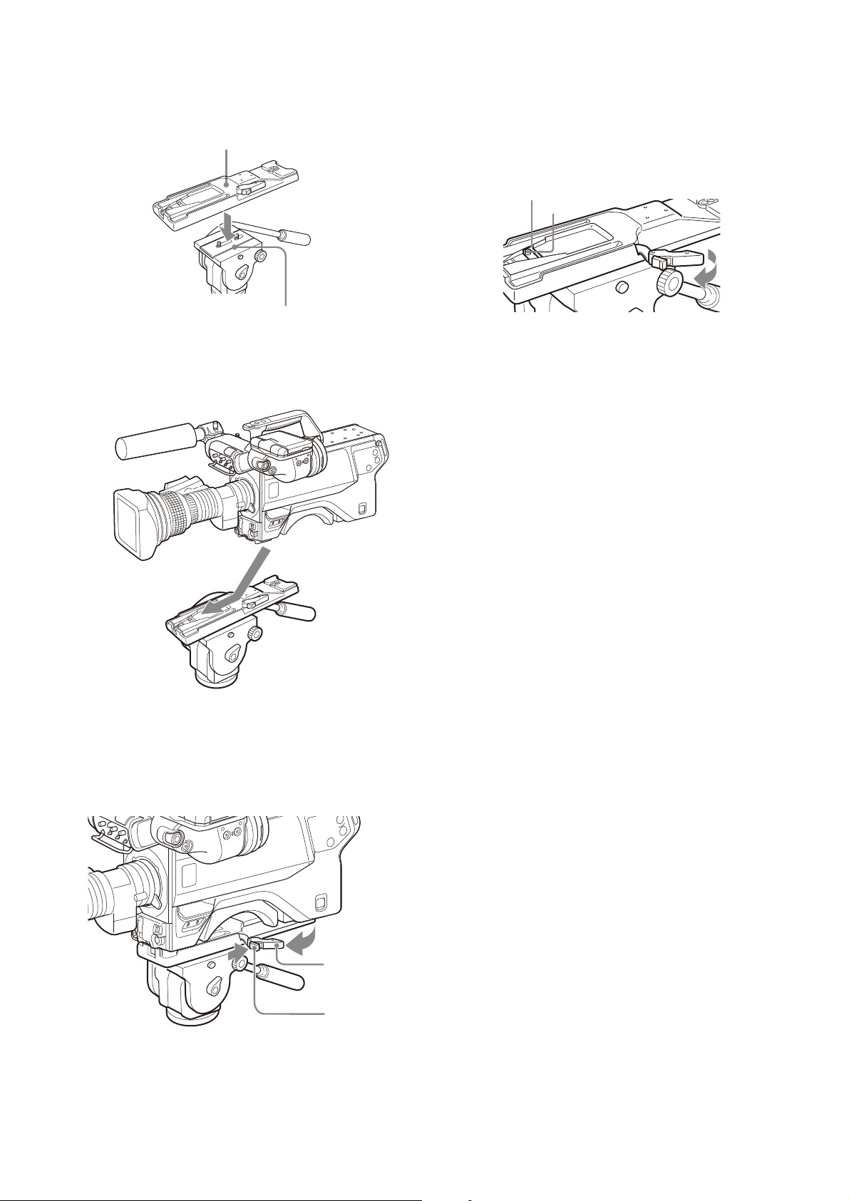
Mounting procedure
Tripod attachment
Platform of the tripod
Lever
Red button
Original position
Pin
1 Attach the tripod attachment to the tripod and
secure it with the screw.
2 Place the camera on the tripod attachment, and slide
forward it along the groove of the tripod attachment
until it clicks.
If the pin of the tripod attachment does not return
to its original position
After removing the camera, if the pin of the tripod
attachment does not return to its original position, hold
down the red button and move the lever in the direction of
the arrow to return the pin to its original position. It is not
possible to mount a camera with the pin not seated.
3 Make sure that the camera is securely attached by
moving it back and forth.
To remove the camera from the tripod attachment
Hold down the red button and pull the lever in the direction
of the arrow.
19
Page 20
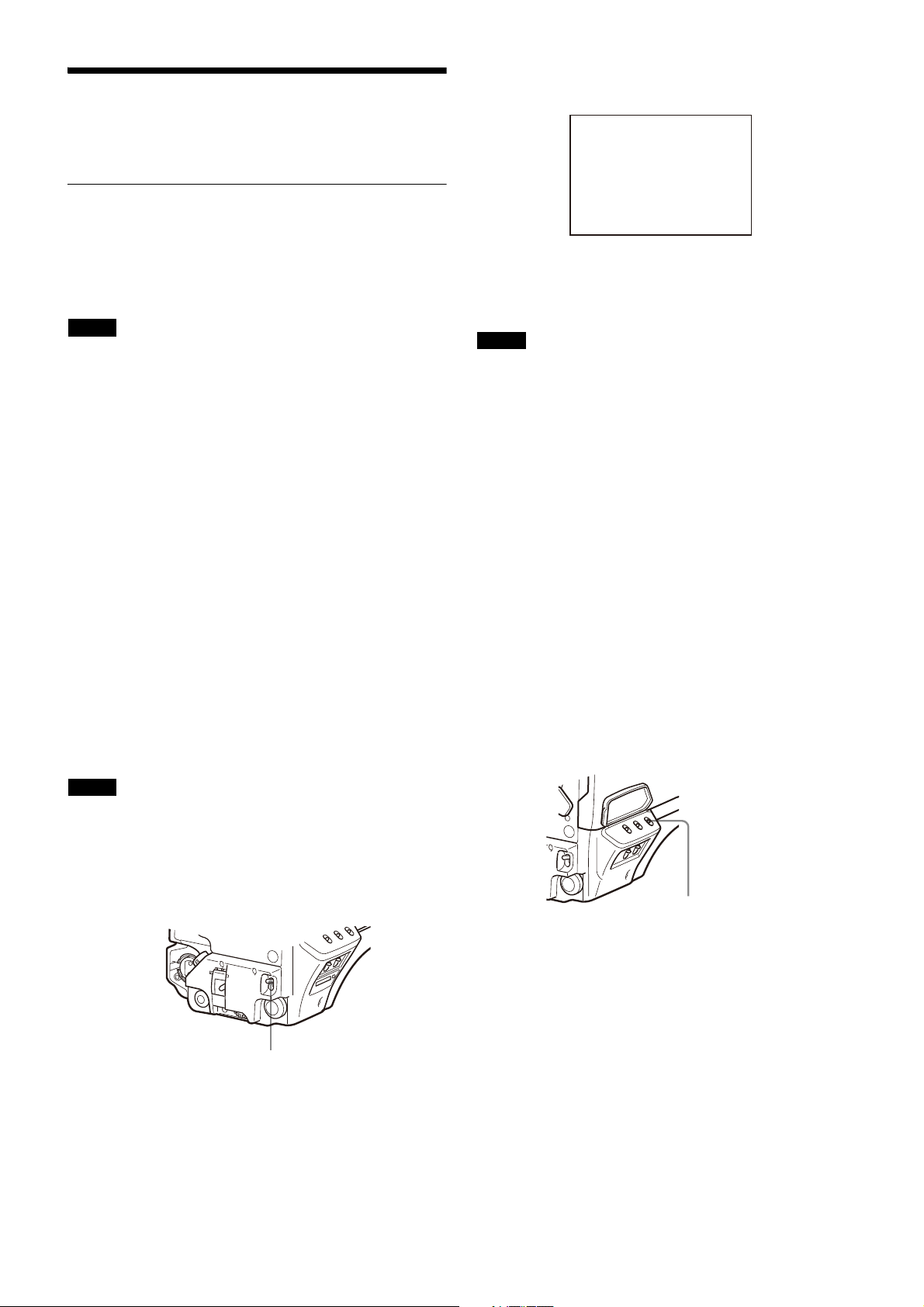
Adjustments and
AUTO W/B BAL switch
ABB:EXECUTING
WHITE BAL switch
Settings for Shooting
Adjusting the Black Balance and White
Balance
During adjustment, a message like the one in the figure
below will be displayed on the viewfinder screen.
In order to maintain high picture quality, it is necessary to
set the black balance and white balance appropriately for
the conditions.
Note
When a camera control unit or a remote control devicesuch as the MSU or RCP series-is connected, control is
performed from the RCP/MSU, and the switches on the
camera are disabled.
Black balance adjustment
The black balance needs adjustment in situations like the
following:
• The first time the camera is used
• When the camera is used after a long period of disuse
• When the surrounding temperature changes greatly
• When the gain value is changed using the setup menus
Normally, there is no need to adjust the black balance every
time the camera is turned on.
White balance adjustment
Always readjust the white balance when lighting conditions
change.
About the viewfinder screen
After the process of adjusting the black balance or white
balance begins, messages about the progress and results
of the adjustment will be displayed on the viewfinder
screen.
When the adjustment process is completed, the message
“ABB: OK” will be displayed. The adjusted value is
automatically stored in memory.
Notes
• During black balance adjustment, the iris will be
automatically closed.
• During black balance adjustment, the gain switching
circuit will work automatically, and the viewfinder screen
will flicker several times. This is not a malfunction.
When automatic black balance adjustment fails
If the automatic black balance adjustment process does not
end successfully, the error message “ABB: NG” will be
displayed on the viewfinder screen for approximately three
seconds.
If this error message is displayed, try black balance
adjustment again.
If the error message continues to be displayed after several
attempts, the camera requires internal inspection.
About black balance memory
The black balance values stored in memory will be
preserved even when the camera power is turned off.
Adjusting the white balance
1 Set the WHITE BAL switch to A or B.
Note
Adjusted values set through automatic adjustment, and
other settings, are stored in the camera’s memory and
preserved even when the camera power is turned off.
Adjusting the black balance
Push the AUTO W/B BAL switch toward BLK (downward).
Automatic adjustment of black balance begins.
In automatic adjustment of black balance, both the black
set and black balance are adjusted.
2 Select the filter setting according to the lighting
conditions.
To select the ND filter
Press the ND filter select button while holding the
FILTER LOCAL button depressed.
Each press of the select button switches the available
ND filters (CLEAR, 1/4ND, 1/8ND, 1/16ND,1/64ND) in
sequence.
To select the CC filter
Press the CC filter select button while holding the
FILTER LOCAL button depressed.
Each press of the select button switches the available
CC filters (cross, 3200K, 4300K, 6300K) in sequence.
20
Page 21
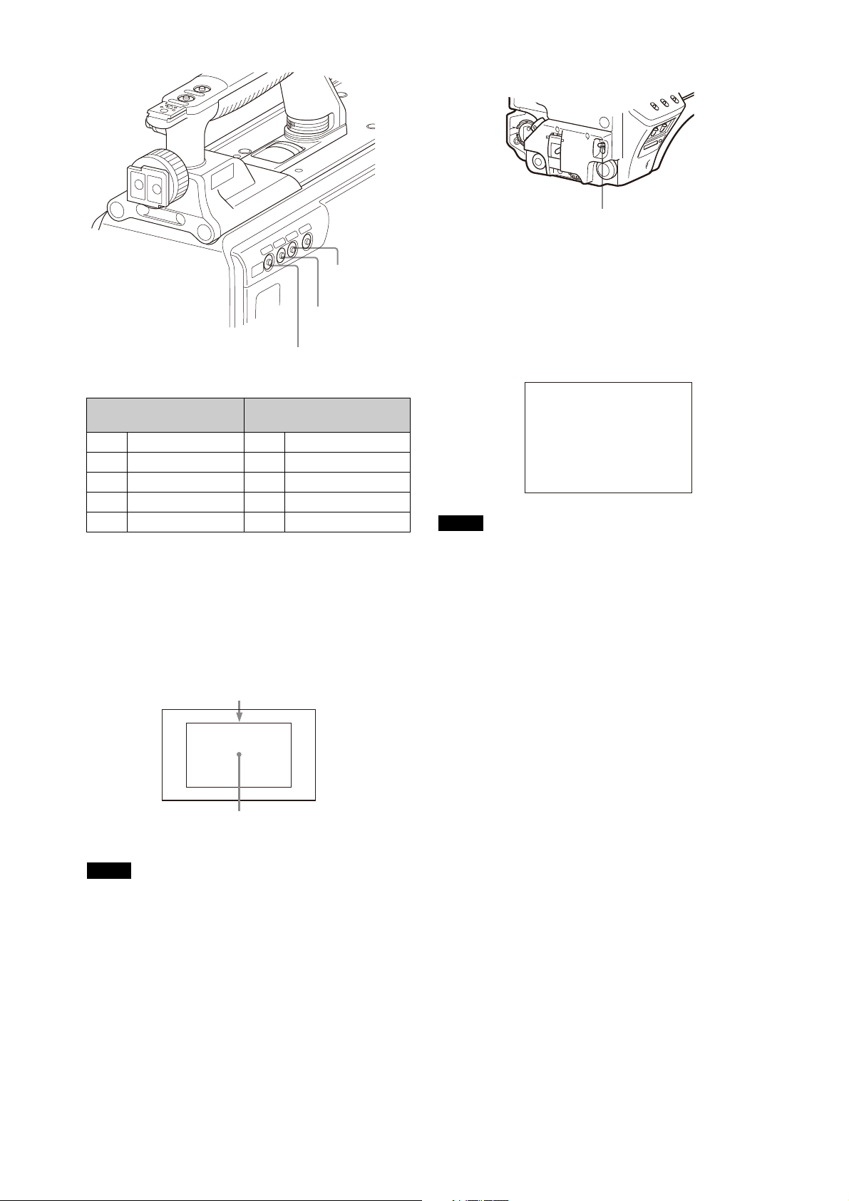
5 Push the AUTO W/B BAL switch to WHT (up).
FILTER LOCAL
button
ND filter select
button
CC filter select
button
A rectangle centered in the screen. The length of the sides
must be at least 70% of the height and width of the screen.
Within this rectangle, there must be an area of white
greater than 10% of the entire screen.
AUTO W/B BAL switch
White balance automatic adjustment begins.
During adjustment, the message “AWB: EXECUTING” will be
displayed on the viewfinder screen.
A message like the one in the figure below will be
displayed, and the adjustment process will complete. The
adjusted value will be automatically stored in the memory
(A or B) selected in step 1.
ND filter Color temperature
conversion filter
1CLEAR Across filter
2 1/4 ND B 3200K (clear)
31/8 ND C4300K
4 1/16 ND D 6300K
51/64 ND
3 Place a white pattern in the same lighting conditions
as the subject, and zoom in on it so that a white area
is obtained in the screen to satisfy the positional and
quantitative requirements illustrated below.
A white object (white cloth, a white wall, etc.) near the
subject may be used in place of a white pattern.
AWB:OK
Note
When using a zoom lens with automatic iris control
capability, hunting1) may occur. Adjust the lens’ iris gain
control (labeled IG, IS, S, etc.).
1)
Hunting: The automatic iris responds over and over, and the
image repeatedly darkens and lightens.
For more information, refer to the lens’ operation manual.
When automatic white balance adjustment fails
If the white balance adjustment process does not end
successfully, the error message “AWB: NG” will be
displayed on the viewfinder screen for approximately three
seconds.
If this error message is displayed, try white balance
adjustment again.
If the error message continues to be displayed after several
attempts, the camera requires internal inspection.
Note
Be careful not to have any spots of high illumination in
the rectangle.
4 Adjust the lens iris opening.
With a manually adjusted lens: Set the opening to an
appropriate value.
With a lens which has automatic iris control: Set the
lens’ automatic/manual iris control switch to
automatic.
When there is no time to adjust the white balance
Set the WHITE BAL switch to PRST. The white balance will be
set automatically according to the filter settings.
About white balance memory
The white balance values stored in memory will be
preserved even when the camera power is turned off.
There are two white balance memories, A and B. When the
AUTO W/B BAL switch is pushed to the WHT side, the white
balance will be adjusted automatically according to the
filter settings. The adjusted value will be stored in the
selected memory. Each memory can store up to five
adjusted values, for a total of 10.
21
Page 22
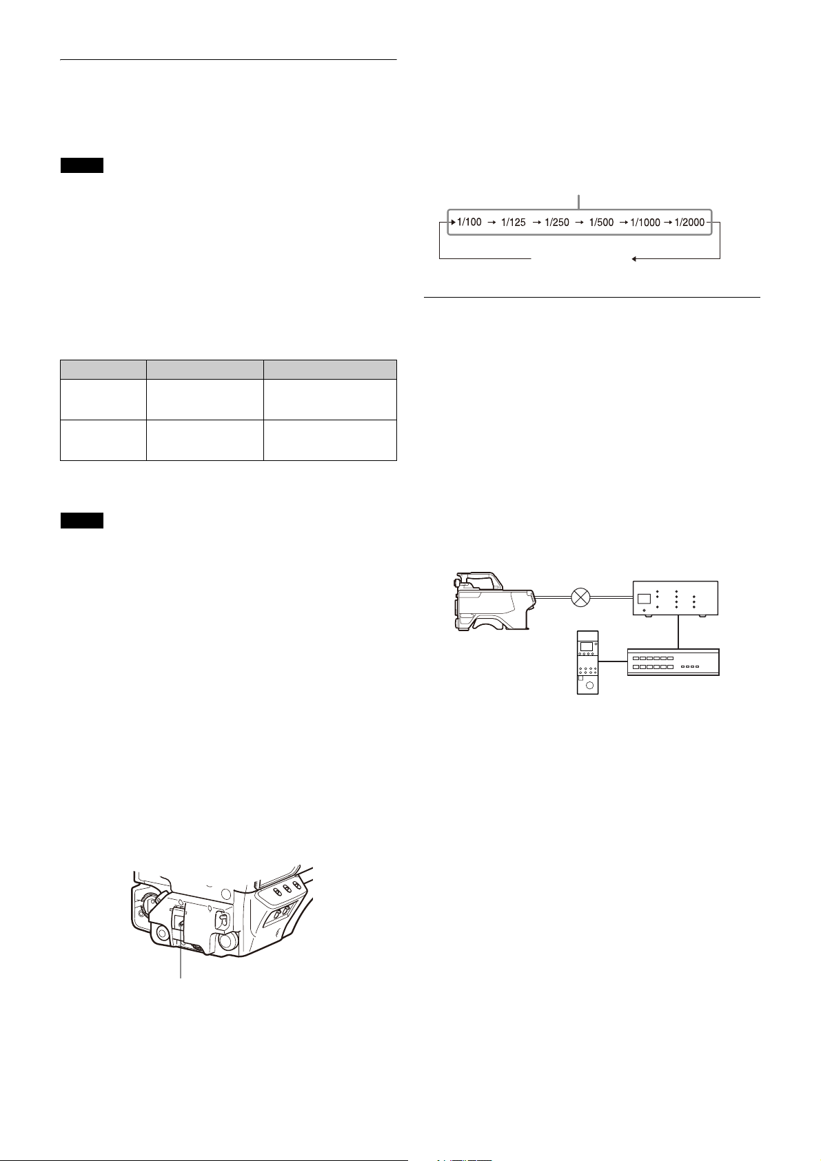
Setting the Electronic Shutter
SHUTTER switch
Standard mode
ECS mode
HDC5500/3500
RS-422A/RS-232C
Network hub
CNA-1
1) 2)
RCP-3000/1000
series
3)
This section explains the different modes which can be
used for the electronic shutter and gives the procedures for
setting the shutter mode and shutter speed.
Note
When a camera control unit or a remote control device,
such as MSU-1000/1500 Master Setup Unit and RCP-1500/
1000 series Remote Control Panel, is connected, the
electronic shutter is controlled from the external control
device and control on the camera are disabled.
About the shutter modes
The shutter modes that can be used with the electronic
shutter of the camera and the shutter speeds that may be
selected are as follows:
Shutter modes and speeds
Shutter mode Shutter speeds* Usage
Standard 1/100, 1/125, 1/250,
ECS (Extended
Clear Scan)
* The values in the table are those with 59.94i. With other formats,
the available values are different.
1/500, 1/1000, 1/2000
seconds
Continuously variable
in the range of
59.96 Hz to 4300 Hz
Note
With artificial lighting, particularly fluorescent lights and
mercury vapor lamps, the brightness appears to be constant,
but in fact the strength of the red, green, and blue
components varies with the power supply frequency. This
phenomenon is known as “flicker.” When using the electronic
shutter under these lighting conditions, there are certain
cases in which the flicker is more noticeable. In particular,
color flicker is evident when the power frequency is 60 Hz. In
areas where the power frequency is 50 Hz, setting the shutter
speed to 1/100 second will reduce the flicker.
Use to obtain clear images
of quickly moving subjects
Use to obtain images on
video monitors without
horizontal striping
2 Push the SHUTTER switch to the SEL position again
before the display disappears. Repeat this action
until the desired mode or speed is displayed.
When all modes and speeds are displayed, they will be
displayed in the following order:
Example: with 59.94i
Setting the Transport Conversion
Function
This function converts the communications protocol from
the camera network system protocol to the simple protocol
internally in the HDC5500/3500.
Using the simple protocol for communication between the
HDC5500/3500 and CNA-1 (RS-422A/RS-232C) enables
camera control using transmission lines or networks that do
not support the camera network system protocol or which
have high latency, such as wireless networks.
You can toggle this function on/off on the <SIMPLE
PROTOCOL> page
(page 63)
For details about configuring the CNA-1, refer to the
operation manual of the CNA-1.
.
Selecting the shutter mode and speed
The shutter mode, and the shutter speed in standard mode,
are set using the SHUTTER switch.
Setting the shutter mode, and shutter speed in
Standard mode
1 Push the SHUTTER switch from the ON position to the
SEL position.
The current shutter setting will be displayed in the
setting change/adjustment process message display
area of the viewfinder screen for about three seconds.
Example: “SHUTTER: 1/250”
1)
Connect the RS-422A/RS-232C cable to the I/O connector of the
CNA-1.
2)
Set CNS Mode to Bridge, and Emulation Mode to CAM.
3)
Set CNS Mode to Bridge.
Transmission lines/networks that support the
simple protocol
Transmission lines/networks that meet the following
conditions are supported.
• Latency: 1 second or lower (one way)
• Bandwidth: 100 kbps or higher
Connectors used for simple protocol
communication
Use one of the following connectors on the HDC5500/3500.
• REMOTE connector on the connector panel (supports
RS-422A only)
• CRANE connector on the connector panel (supports
RS-422A/RS-232C)
• I/O connector on the HKC-WL50 Wireless Transmission
Adaptor (option) (supports RS-422A/RS-232C)
Change the PORT setting on the <SIMPLE PROTOCOL> page
for the connector that is used
(page 63)
.
22
Page 23
Setting the Focus Assist Functions
CONTENTS 00 TOP
01.<VF DISPLAY>
02.<'!'IND>
03.<VF MARKER>
04.<VF DETAIL>
05.<FOCUS POSITION METER1
06.<FOCUS POSITION METER2
07.<FOCUS ASSIST>
08.<ZEBRA>
09.<CURSOR>
10.<BOX CURSOR FILE>
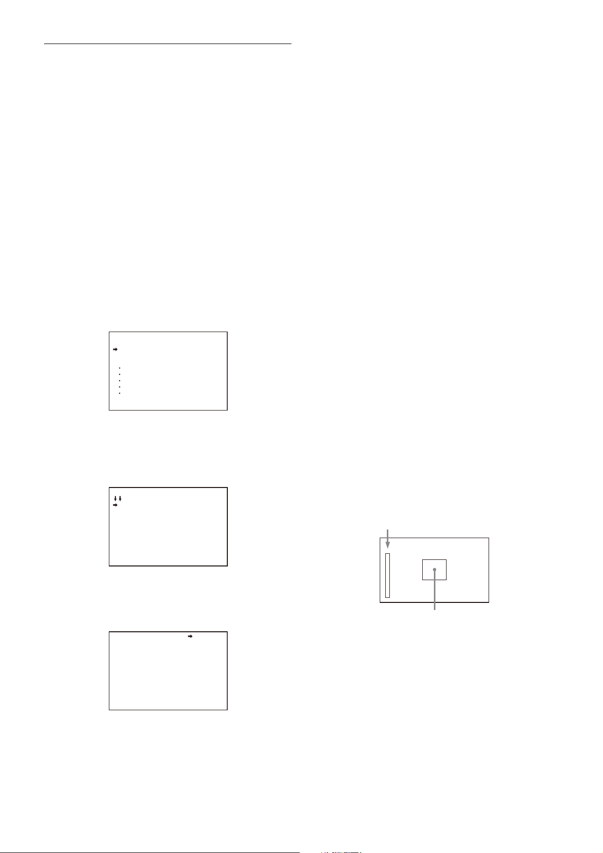
Level indicator (its position and operations can be adjusted.)
Area marker to display the detection area of the focus
(its size and position can be adjusted.)
Using the OPERATION menu, the assist functions for easier
focusing on the viewfinder, can be activated.
Adding the VF detail signal
Adding the VF detail signal to sharp edges in the image on
the viewfinder screen makes it easier to check the focusing
condition by observing changes in the detail signal or in the
color converted from the detail signal (color detail).
The focus setting where the detail signal becomes
strongest is the best focus setting.
1 Turn on the camera.
2 Set the DISPLAY switch to MENU while holding the
MENU SEL knob/ENTER button pressed.
The camera enters Menu mode, and “TOP” is displayed
at the upper right corner of the screen.
3 Rotate the MENU SEL knob/ENTER button to align the
arrow marker (
SEL knob/ENTER button.
The TOP MENU screen is displayed.
,) to “TOP” and push on the MENU
<TOP MENU>
USER
USER MENU CUSTOMIZE
ALL
OPERATION
PAINT
MAINTENANCE
FILE
DIAGNOSIS
can adjust the signal level (strength) in the range of 0 to
100% (default 25%).
You can adjust the characteristics of the detail signal
with the menu items below.
CRISP: Adjust to eliminate fine portions of the detail
signal.
FREQUENCY: Change the detection band of sharp
edges.
FLICKER: Turn ON/OFF the function to flicker the detail
signal, which makes it easier to check the signal on
a viewfinder screen.
AREA: To limit the area where to display the detail
signal.
ZOOM LINK: Set the VF detail level at the full WIDE
position. (The VF detail level changes according to
the zoom position.)
To use the color detail
Set COLOR DETAIL to ON to convert the VF detail signal
to a specified color. This makes it easier to check the
signal on an LCD screen, including the viewfinder
screen. The display color can be selected at the column
next to ON.
You can adjust the coloring with the menu items below.
PEAK COLOR: Turn ON/OFF the function to change the
color where the detail signal is strongest.
CHROMA LEVEL: To reduce the chroma components of
the video signal (only for video signals on the
viewfinder).
7 Rotate the MENU SEL knob/ENTER button to display
the desired setting and push on the MENU SEL knob/
ENTER button.
4 Rotate the MENU SEL knob/ENTER button to align the
arrow marker (
MENU SEL knob/ENTER button.
The CONTENTS page of the OPERATION menu is
displayed.
,) to OPERATION and push on the
5 Rotate the MENU SEL knob/ENTER button to align the
arrow marker (
MENU SEL knob/ENTER button.
The <VF DETAIL> page is displayed.
,) to <VF DETAIL> and push on the
<VF DETAIL> 04 TOP
VF DETAIL : ON (25%)
CRISP : 0
FREQUENCY: 9M
FLICKER : OFF
AREA : 70%
ZOOM LINK: ON 100%
COLOR DETAIL : ON BLUE
PEAK COLOR : ON
CHROMA LEVEL: 100%
6 Rotate the MENU SEL knob/ENTER button to align the
arrow marker (
the MENU SEL knob/ENTER button.
To use the VF detail signal
Set VF DETAIL to ON to activate the VF detail function to
add the detail signal to sharp edges in the image. You
,) to the item to be set and push on
8 To finish the adjustment, set the DISPLAY switch to
OFF to exit Menu mode.
Displaying the focus assist indicators
The focus assist indicator function extracts the irregularities
of a subject and converts the integrated values to a level
indicator, which shows the focus condition.
The focus setting where the indicator shows the maximum
level is the best focus setting. (The range of the indicator
substantially changes depending on picture elements or
shooting environments. Adjust it with GAIN and OFFSET as
required.)
1 Display the CONTENTS page of the OPERATION menu
(referring to step 1 to 4 in “Adding the VF detail
signal”).
2 Rotate the MENU SEL knob/ENTER button to align the
arrow marker (
the MENU SEL knob/ENTER button.
23
,) to <FOCUS ASSIST> and push on
Page 24
The <FOCUS ASSIST> page is displayed.
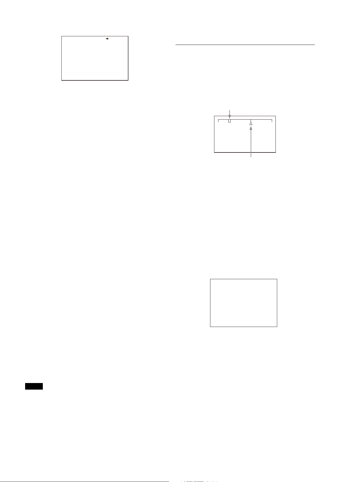
Current focus position (index)
Registered focus position (marker)
<FOCUS POSITION METER1>
FOCUS POSITION METER: ON
NEAR LIMIT : 100 (0~999)
FAR LIMIT : 923 (0~999)
DIRECTION : HORIZONTAL
SIZE : NORMAL
RULED LINE : ON
INDEX COLOR : WHITE
INDEX WIDTH : 1
MARKER WIDTH : 1
CURRENT FOCUS DIST :_5.7M 18.7ft
236 (0~999)
06 TOP
<FOCUS ASSIST> 08 TOP
INDICATOR : OFF
MODE : BOX BOTTOM
LEVEL : 3 QUICK
GAIN : 50
OFFSET : 50
AREA MARKER: ON
SIZE : MIDDLE
POSITION : CENTER
POSITION H: 50
POSITION V: 50
3 Rotate the MENU SEL knob/ENTER button to align the
arrow marker (
the MENU SEL knob/ENTER button.
To use the level indicator
Setting INDICATOR to ON displays the level indicator on
the viewfinder.
You can set the display format with the menu items
below.
MODE: Set the type and position of the indicator.
LEVEL: Set the density and the response speed of the
indicator.
GAIN: Set the sensitivity of the indicator.
OFFSET: Set the offset of the focus detection value.
1)
Normally, the sensitivity of the indicator is automatically set
to the optimum value in conjunction with the AREA MARKER
SIZE set value. Use this setting when an optimum sensitivity
value cannot be obtained, depending on the shooting
environment.
2)
Normally, the optimum offset is automatically set in
conjunction with the AREA MARKER SIZE and MASTER GAIN
set values. Use this setting when the optimum offset cannot
be obtained, depending on the shooting environment.
To use the area marker
Setting AREA MARKER to ON displays the detection
area of the focus as a marker on the viewfinder screen.
You can set the size and position of the detection area
with the menu items below.
SIZE: The size of the detection area can be changed. (If
the area size is too large, both the subject and the
background are included in the area, making the
indicator display may easily deviate from the
subject.)
POSITION: Roughly set the position of the detection
area.
POSITION H: Finely adjust the position of the detection
area in the horizontal directions.
POSITION V: Finely adjust the position of the detection
area in the vertical directions.
4 Rotate the MENU SEL knob/ENTER button to display
the desired setting and push on the MENU SEL knob/
ENTER button.
5 To finish the adjustment, set the DISPLAY switch to
OFF to exit Menu mode.
Notes
• The level indicator and the effect area marker cannot be
displayed simultaneously, whichever you set to ON later
is preferentially displayed.
• The area marker and the aspect safety marker cannot be
displayed simultaneously, whichever you set to ON later
is preferentially displayed.
• When displaying the focus assist indicators, check that
the flange focal length has been precisely adjusted.
See “Adjusting the Flange Focal Length” on page 15 for
the flange focal length.
Setting the Focus Position Meter
Function
The focus position meter function allows you to graphically
display the registered focus position (marker) and the
current focus position (index) graphically on the viewfinder
screen.
,) to the item to be set and push on
NEAR FAR
1)
2)
You can set the focus to the registered point easily by
adjusting the focus until the index position overlaps the
marker position (adjusted state). In the adjusted state, you
can display a color frame and marker name on the
viewfinder screen.
1 Display the CONTENTS page of the OPERATION menu
(referring to steps 1 to 4 in “Adding the VF detail
signal”).
2 Turn the MENU SEL knob/ENTER button to align the
arrow marker (,) to <FOCUS POSITION METER1> or
<FOCUS POSITION METER2>, and press the MENU SEL
knob/ENTER button.
The <FOCUS POSITION METER1> page or <FOCUS
POSITION METER2> page is displayed.
3 Turn the MENU SEL knob/ENTER button to align the
arrow marker (,) to the item to be set and press the
MENU SEL knob/ENTER button.
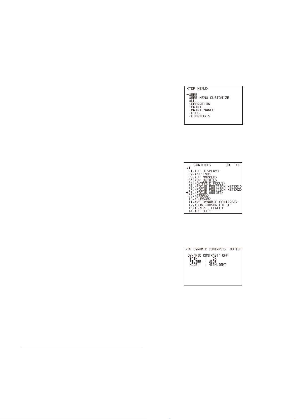
To use the focus position meter
Setting FOCUS POSITION METER to ON displays the
focus position meter on the viewfinder screen.
You can set the display format with the <FOCUS
POSITION METER1> page items below.
NEAR LIMIT: Sets the NEAR edge of the focus position
meter.
FAR LIMIT: Sets the FAR edge of the focus position
meter.
The focus position range to display varies depending on
the NEAR LIMIT and FAR LIMIT settings. The full range is
displayed by setting NEAR LIMIT to 0 and FAR LIMIT to
999.
24
Page 25
DIRECTION: Selects whether to display the meter
horizontally at the top of the screen or vertically on
the right edge of the screen.
SIZE: Sets the size of the meter.
RULED LINE: Turns the display of guide lines on the
meter on/off.
INDEX COLOR: Sets the color of the index.
INDEX WIDTH: Sets the width of the index.
MARKER WIDTH: Sets the width of the marker.
To set the adjustment sensitivity and display content
You can set the adjustment sensitivity and configure
the display in the adjusted state using ADJUSTED SIGN
on the <FOCUS POSITION METER2> page.
SENSE: Sets the adjustment sensitivity. Increasing the
value increases the sensitivity (making
determination of adjusted state more precise).
NAME DISP: Turns the display of the marker name in
the adjusted state on/off (DISPLAY screen only).
FRAME DISP: Turns the display of a color frame
(adjustment frame) on the screen in the adjusted
state on/off.
FRAME WIDTH: Sets the width of the adjustment
frame.
To configure the marker display settings
You can set the marker display using MARKER CONFIG
on the <FOCUS POSITION METER2> page.
REG: Registers a marker at the index position.
DISP: Turns the marker display on/off.
COLOR: Sets the color of the marker. This also sets the
color of the adjustment frame.
NAME: Sets the name of the marker.
POS: Adjusts the marker position manually.
1 Turn on the camera.
2 Set the DISPLAY switch to MENU while holding the
MENU SELECT knob pressed.
The camera enters Menu mode, and “TOP” is displayed
at the upper right corner of the screen.
3 Turn the MENU SELECT knob to align the arrow
marker () to “TOP” and press the MENU SELECT
knob.
The TOP MENU screen appears.
4 Turn the MENU SELECT knob to align the arrow
marker () to OPERATION and press the MENU
SELECT knob.
The CONTENTS page of the OPERATION menu is
displayed.
4 Turn the MENU SEL knob/ENTER button to display
the desired setting and press the MENU SEL knob/
ENTER button.
5 To finish the adjustment, set the DISPLAY switch to
OFF to exit Menu mode.
Marker registration
You can register a marker for the focus position meter using
RET/ASSIGNABLE buttons A, B, and C.
When HDLA is attached, you can register a marker for the
focus position meter using the VF OUT switch. Marker 1 is
registered using the R switch, marker 2 by the G switch, and
marker 3 by the B switch. Setting a switch to ON registers a
marker at the current index position (same function as REG
on the <FOCUS POSITION METER2> page). Setting a switch to
OFF turns the marker display off (same as setting DISP on the
<FOCUS POSITION METER2> page to OFF).
To register a marker for the focus position meter
using the VF OUT switch
Set VF OUT SW to FOCUS POSITION METER on the <SWITCH
ASSIGN1> page in the OPERATION menu.
Setting the VF Dynamic Contrast
Function
Emphasizing the contrast in the image on the viewfinder
screen makes it easier to check the focusing condition for
high brightness areas and for subjects with low contrast
levels.
5 Turn the MENU SELECT knob to align the arrow
marker () to <VF DYNAMIC CONTRAST> and press
the MENU SELECT knob.
The <VF DYNAMIC CONTRAST> page is displayed.
6 Turn the MENU SELECT knob to align the arrow
marker () to the item to be set and press the MENU
SELECT knob.
To use the VF dynamic contrast signal
Set DYNAMIC CONTRAST to ON to add the contrast
signal in the image. You can adjust the GAIN in the
range of 0 to 100%.
You can adjust the characteristics of the contrast signal
with the menu items below.
FILTER: Adjust the selection range of the contrast
extraction target pixel.
MODE: Selection of contrast signal addition mode.
LINEAR adjusts the contrast of the entire image.
HIGHLIGHT emphasizes the contrast of the high
brightness range. FOGGY emphasizes the contrast
of the image which is hazy and in low contrast.
25
Page 26
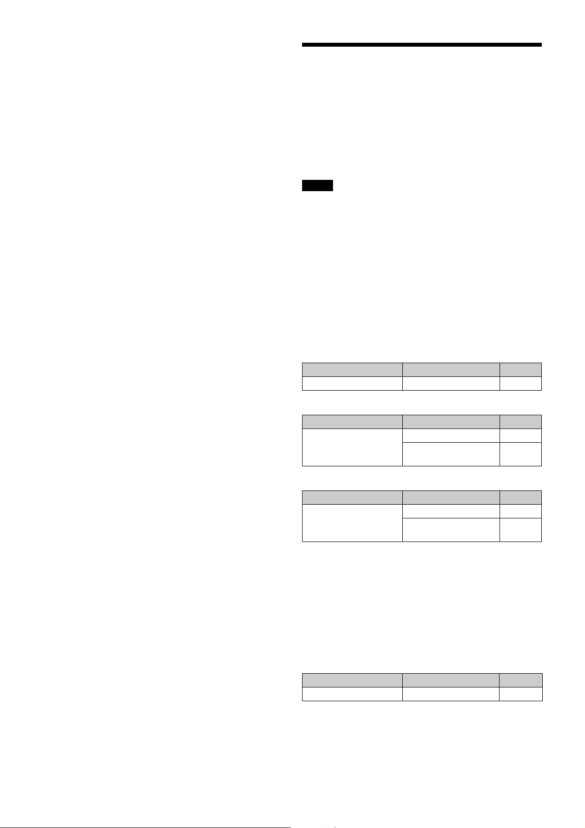
7 Turn the MENU SELECT knob to display the desired
setting and press the MENU SELECT switch.
8 To finish the adjustment, set the DISPLAY switch to
OFF to exit Menu mode.
Setting the Camera Outputs
You can specify video signals directly output from the
camera, with menu operations.
You can display the signal name by attaching a label
(supplied) for the configured output signal name to the
connector label area.
Notes
• The MAIN (camera picture), RET (return video), or VF (the
same picture as that displayed on the viewfinder screen)
setting is common to SD-SDI and VBS. Different signals
cannot be output.
• The output from the SDI MONI connector is 1080i, even if
the format setting is 720P.
Outputting the signal being shot (camera
picture)
The same textual information as that displayed on the
viewfinder screen can be added to the output signal by
setting CHARACTER to “ON” on the <SDI OUT> or <TEST
OUT> page.
To output as HD-SDI
Menu page Item Setting
<SDI OUT> SDI-MONI OUT MAIN
To output as SD-SDI
Menu page Item Setting
<SDI OUT> SDI-MONI OUT SD-SDI
DOWN CONVERTER
SELECT
To output as VBS
Menu page Item Setting
<TEST OUT> OUTPUT VBS
DOWN CONVERTER
SELECT
MAIN
MAIN
Constantly outputting a return video
• When a camera control unit is connected, one of the
signals being supplied to the camera control unit can be
output from the camera.
• The last selected return signal is output.
• The same textual information as that displayed on the
viewfinder screen can be added to the output signal by
setting CHARACTER to “ON” on the <SDI OUT> or <TEST
OUT> page.
To output as HD-SDI
Menu page Item Setting
<SDI OUT> SDI-MONI OUT RET
26
Page 27
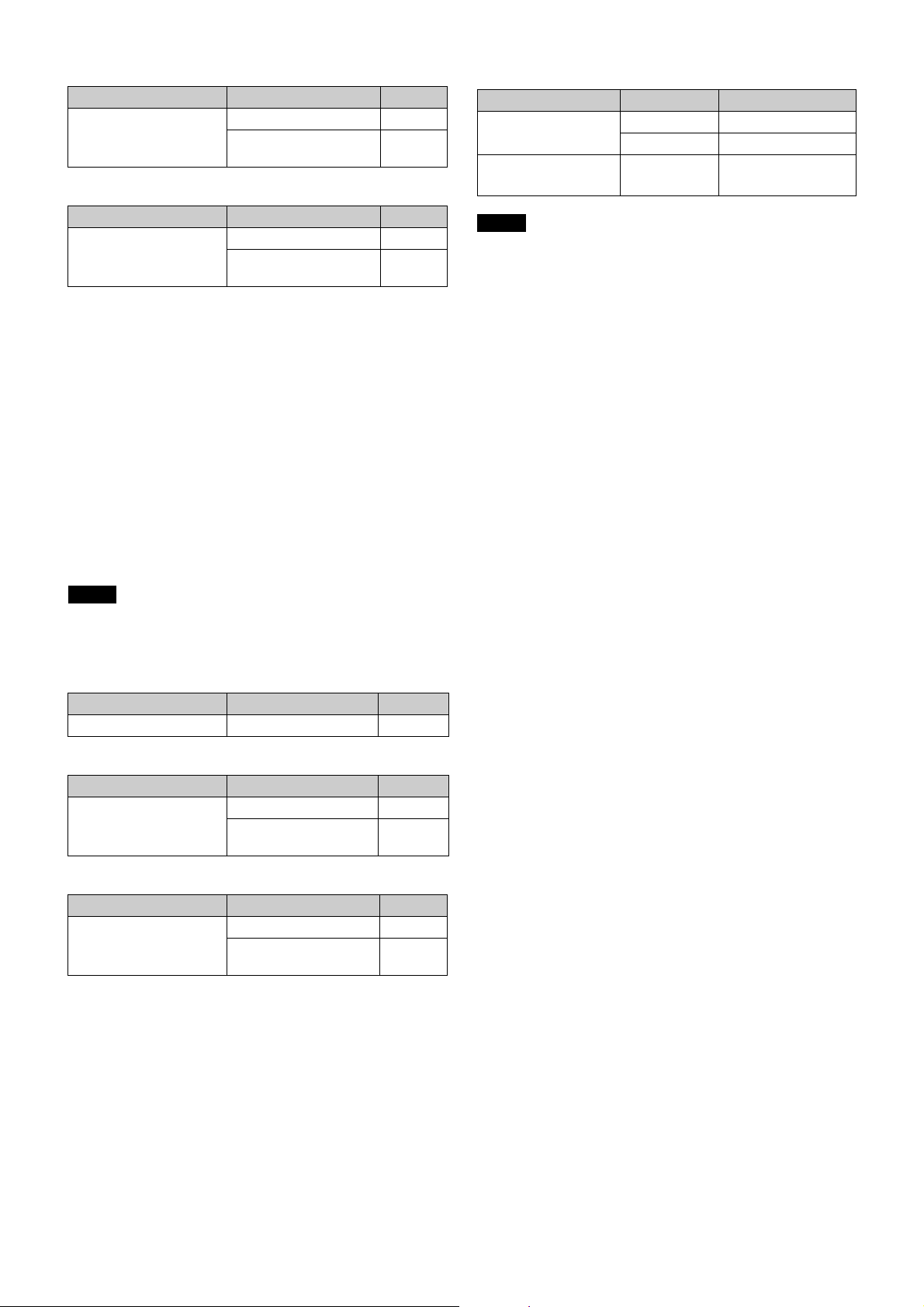
To output as SD-SDI
Menu page Item Setting
<SDI OUT> SDI-MONI OUT SD-SDI
DOWN CONVERTER
SELECT
RET
To output as VBS
Menu page Item Setting
<TEST OUT> OUTPUT VBS
DOWN CONVERTER
SELECT
RET
Outputting the same image as that on the
viewfinder screen
• With HD-SDI, you can obtain a signal that includes the
same information as that being displayed on the
viewfinder screen according to the settings of the VF
MARKER, CHARACTER, VF DETAIL, ZEBRA, etc. The ON/
OFF or other settings for adding information are common
to those for the viewfinder. The output is synchronized
with switching among Y, R, G, and B or switching to a
return signal.
• With SD-SDI or VBS, the output is synchronized only with
switching between a return signal and the camera image.
It does not correspond to switching among Y, R, G, and B.
Information other than CHARACTER (such as VF MARKER,
VF DETAIL, ZEBRA) cannot be added to the output.
To output in 1080/59.94P or 1080/50P
Menu page Item Setting
<OUTPUT FORMAT> ACTIVE LINE 1080
(Format) 59.94P or 50P
<SDI OUT> SDI-1
SDI-2
Notes
• HZC-PRV50/PRV50M/PRV50W camera operating
software (option) is required for 3G-SDI output.
• Output as standard when an HKC-TR37 is installed.
MAIN (3G)
LEVEL-A or LEVEL-B
Note
With the settings for outputting the same image as that on
the viewfinder screen, the output will be obtained in 1080i,
even if the format setting is 720P.
To output as HD-SDI
Menu page Item Setting
<SDI OUT> SDI-MONI OUT VF
To output as SD-SDI
Menu page Item Setting
<SDI OUT> SDI-MONI OUT SD-SDI
DOWN CONVERTER
SELECT
VF
To output as VBS
Menu page Item Setting
<TEST OUT> OUTPUT VBS
DOWN CONVERTER
SELECT
VF
Outputting 3G/6G/12G-SDI (HDC5500)
The SDI 1 output and SDI 2 output form 3G/6G/12G-SDI
output.
For details, see “SDI output format with master frequency
of 1/1.001” (page 64) and “SDI output format with master
frequency of 1/1.000” (page 77).
Outputting 3G-SDI (HDC3500)
The SDI 1 output and SDI 2 output form 3G-SDI output.
27
Page 28
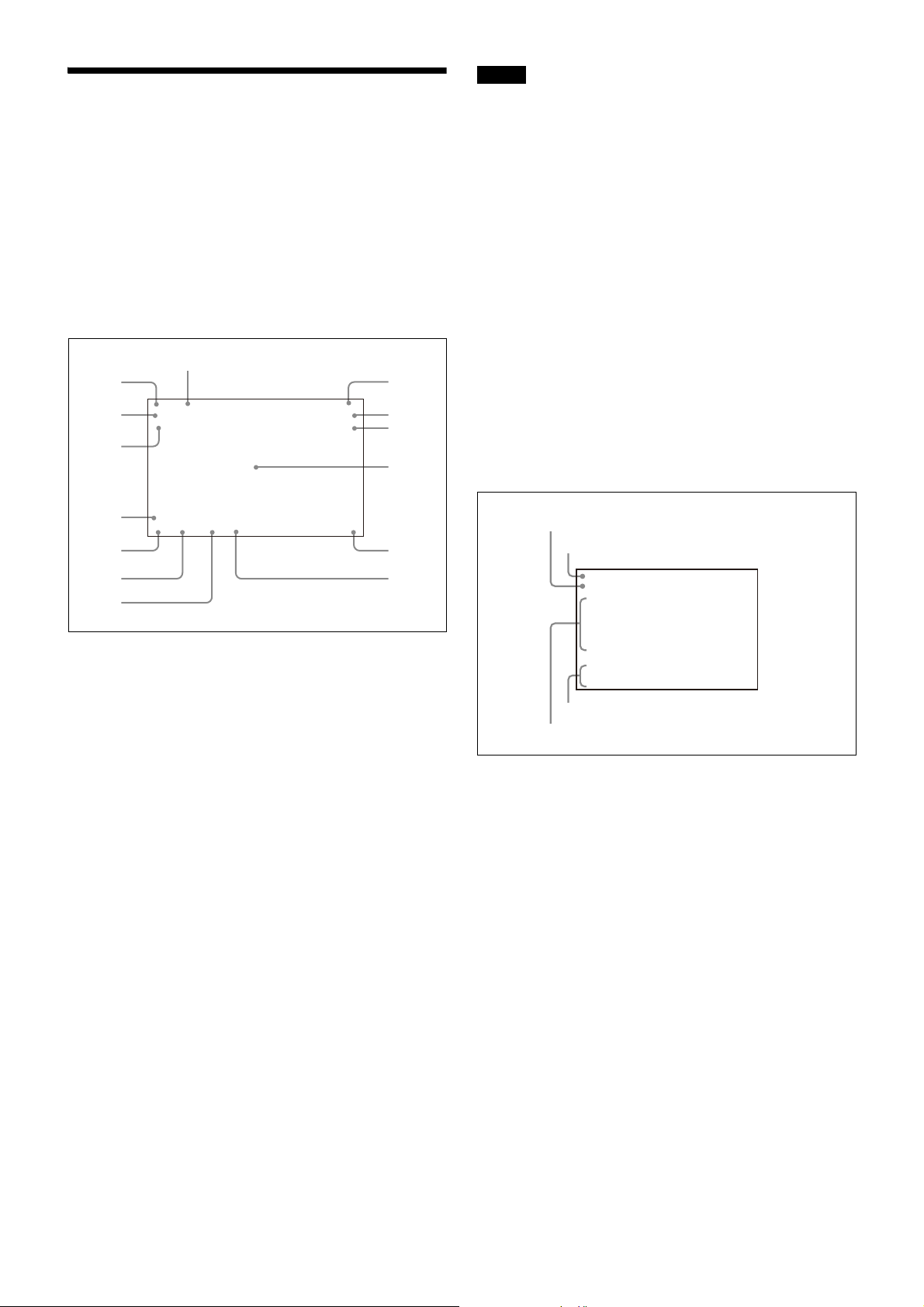
Viewfinder Screen Status
1
2
3
4
5
6
7
8
9
0
qd
qf
qs
qa
1080-59.94i
ASSIGNABLE :OFF
!ND :2
!CC :C
!FAN :MAX
!EXT :ON
!FORMAT :1080-59.94i
OPT LV CAM:ssxxxxxxb
CCU:ssxxxxxxb
a
c
d
b
Display
Besides the video image, the viewfinder can display text
and messages showing the camera settings and operation
status, as well as items such as a center marker or safety
zone marker.
When the DISPLAY switch is set to DISPLAY
Items set to ON using the menu or related switches will be
displayed on the upper and lower edges of the screen.
EX Z55
D.EX
TALK
5600K
1A A
W:
0dB 1/125
F255
12.5V
DOOR No1
F5.6
Note
Displayed only when a serial communication lens is
connected.
j Battery voltage
Displays the input voltage.
k Marker name of the focus position meter
Displays the marker name of the focus position meter.
l Setting change / adjustment process message area
This area is only used when the MESSAGE item of the menu
is set to other than OFF.
m F value
Indicates the lens F (iris opening) value.
n Shutter/ECS
Displays the shutter/ECS status. Nothing is displayed if the
electronic shutter is set to OFF.
When you press the STATUS/CANCEL switch
toward STATUS
The status display is changed to show the following items:
a Zoom position
Indicates the approximate position of the zoom lens
variator between wide angle (0) and telephoto (99). Shows
how close it is to the telephoto side.
b Lens extender
“EX” is displayed when a lens extender is in use.
c Digital extender
“D.EX” is displayed when a digital extender is in use.
d TALK indication
Displayed when the intercom microphone is set to ON.
e 5600K mode
Displayed when 5600K is set to ON.
f Filter
Displays the type of filter currently selected. The number (1,
2, 3, 4, or 5) indicates the ND filter, and the letter (A, B, C, or
D) is for the CC filter.
g White balance memory
Displays the currently selected white balance automatic
adjustment memory.
W:A: The WHITE BAL switch is set to “A”
W:B: The WHITE BAL switch is set to “B”
W:P: The WHITE BAL switch is set to “PRST”
h Gain value
Displays the video gain value (dB) set with the GAIN switch.
i Focus position
Shows the focus position of a zoom lens as a numeric value
(0 to 255 (infinity)).
a Assignable switch indication
The function assigned to the assignable switch
(page 9)
is
indicated.
For the functions that can be assigned, see OPERATION
menu <SWITCH ASSIGN1> (page 44).
b Format indication
The current video format is displayed.
c ‘!’ indication area
This area is used to display abnormal statuses, using the
<‘!’IND> function. Display options can be set, using the
menu.
For details, see OPERATION menu <‘!’ IND> (page 40).
d Light sensor level indicators (optical fiber
transmission only)
This area shows the light-receiving levels in segments.
CAM: Light-receiving level at the CCU connector
(page 10)
of the camera
CCU: Light-receiving level at the CAMERA connector of the
CCU
28
Page 29
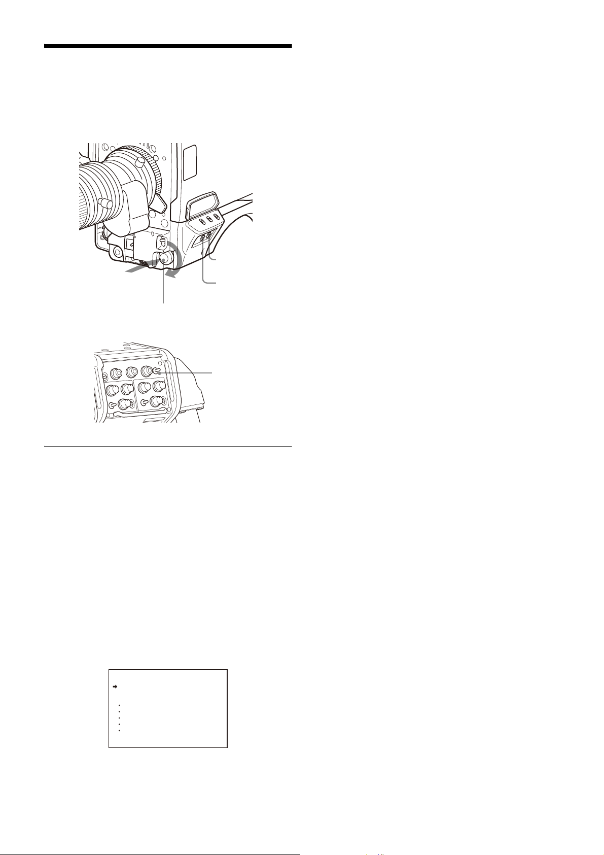
Menu Operations
DISPLAY switch
STATUS/CANCEL
switch
MENU SEL knob/ENTER button
Push on
Rotate
DISP/MENU switch
The menus displayed on the viewfinder screen enable
various settings of the camera.
The following controls are used to operate the menus.
To disable the “TOP” indication
Turn the power once off then on again, or set the DISPLAY
switch from OFF to MENU while holding the STATUS/
CANCEL switch pressed toward CANCEL. This disables the
TOP selection.
Available menus
USER menu
This menu can include menu pages selected from among
the OPERATION, PAINT, MAINTENANCE, FILE, and
DIAGNOSIS menus, for convenience. Changing, adding,
and deleting pages can be performed with the USER MENU
CUSTOMIZE menu.
USER MENU CUSTOMIZE menu
This menu allows you to edit the USER menu.
For details on the USER menu, see “Editing the USER Menu”
on page 31.
ALL menu
This menu permits you to control all items of the
OPERATION menu, PAINT menu, MAINTENANCE menu, FILE
menu, and DIAGNOSIS menu as a single menu.
OPERATION menu
This menu contains items for camera operators to operate
the camera. It mainly permits viewfinder, intercom, and
switch settings.
Starting Menu Operations
To display a menu page
Set the DISPLAY switch from OFF to MENU.
You can also display the menu by setting the DISP/MENU
switch on the rear side to MENU.
The menu page that last operated will be displayed. (If it is
the first time, the CONTENTS page of the OPERATION menu
will be displayed.)
To display the TOP MENU screen
If you set the DISPLAY switch from OFF to MENU while
holding the MENU SEL knob/ENTER button pressed, “TOP”
is displayed at the upper right corner of the screen.
Selecting it displays the TOP MENU screen, which lists the
available menus, and you can select the menus on this
screen.
TOP MENU screen
<TOP MENU>
USER
USER MENU CUSTOMIZE
ALL
OPERATION
PAINT
MAINTENANCE
FILE
DIAGNOSIS
PAINT menu
This menu contains items for making detailed image
adjustments while using a waveform monitor to monitor
the waveforms output from the camera. Support of a video
engineer is usually required to use this menu.
Although you can also use an external remote control panel
or master setup unit to set the items on this menu, the
menu is effective when using the camera by itself outdoors.
MAINTENANCE menu
This menu contains items for performing camera
maintenance operations, such as changing the system or
setting infrequently used “paint” items.
FILE menu
This menu is for performing file operations, such as writing
or clearing the reference file.
DIAGNOSIS menu
This menu enables you to confirm the self-diagnostic
information.
To select a menu on the TOP MENU screen
1 Rotate the MENU SEL knob/ENTER button to align the
arrow marker (
,) with the desired menu indication.
2 Push on the MENU SEL knob/ENTER button.
The CONTENTS page or the last operated page of the
selected menu is displayed.
29
Page 30
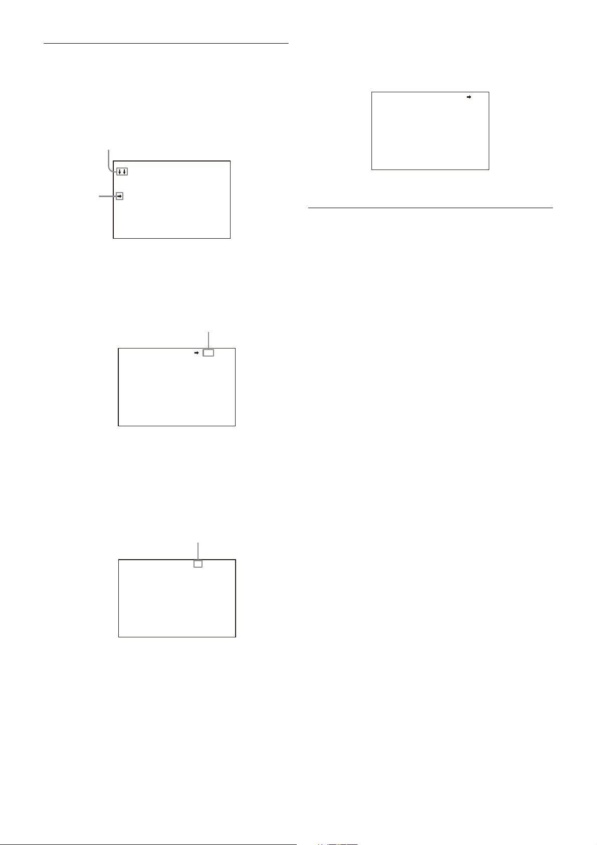
Selecting Pages
If the screen can be scrolled, arrows will
indicate the direction of scrolling.
, marker
Example: CONTENTS page of the OPERATION menu
Page number
Flashes
When selecting a page from a CONTENTS
page
CONTENTS 00 TOP
01.<VF DISPLAY>
02.<'!'IND>
03.<VF MARKER>
04.<VF DETAIL>
05.<FOCUS POSITION METER1
06.<FOCUS POSITION METER2
07.<FOCUS ASSIST>
08.<ZEBRA>
09.<CURSOR>
10.<BOX CURSOR FILE>
Rotate the MENU SEL knob/ENTER button to align the arrow
marker (
,) with the desired page indication, then push on
the MENU SEL knob/ENTER button.
The selected page is displayed.
<VF DETAIL> 04 TOP
VF DETAIL : ON 25%
CRISP : 0
FREQUENCY: 9M
FLICKER : OFF
AREA : 70%
ZOOM LINK: ON 100%
COLOR DETAIL : ON BLUE
PEAK COLOR : ON
CHROMA LEVEL: 100%
To change the displayed page
1 Check that the arrow marker (,) is located at the left
of the page number, then push on the MENU SEL
knob/ENTER button.
The arrow marker (
(?) mark.
,) changes to a flashing question
To return to the TOP MENU screen
Align the arrow marker (
,) with “TOP” at the top right of
the menu page then press the MENU SEL knob/ENTER
button.
<VF DETAIL> 04 TOP
VF DETAIL : ON 25%
CRISP : 0
FREQUENCY: 9M
FLICKER : OFF
AREA : 70%
ZOOM LINK: ON 100%
COLOR DETAIL : ON BLUE
PEAK COLOR : ON
CHROMA LEVEL: 100%
The TOP MENU screen is resumed.
Setting the Menu Items
If a “?” mark is flashing at the left of t he page number, push
on the MENU SEL knob/ENTER button to change it to the
arrow marker (,). Setting on the displayed page is
enabled.
1 Rotate the MENU SEL knob/ENTER button to align the
arrow marker (
,) with the desired item.
2 Push on the MENU SEL knob/ENTER button.
The arrow marker (
mark.
,) will change to a flashing “?”
3 Rotate the MENU SEL knob/ENTER button to change
the setting value.
When the knob is rotated quickly, the values will
change quickly; when rotated slowly, the values will
change slowly.
To reset a changed value
If you press the STATUS/CANCEL switch toward CANCEL
before pressing the MENU SEL knob/ENTER button, the
setting will be returned to its previous value.
To interrupt settings
Set the DISPLAY switch to OFF to turn off the menu
screen display.
The setting operation can be restarted by setting the
DISPLAY switch back to MENU.
<VF DETAIL> ? 04 TOP
VF DETAIL : ON 25%
CRISP : 0
FREQUENCY: 9M
FLICKER : OFF
AREA : 70%
ZOOM LINK: ON 100%
COLOR DETAIL : ON BLUE
PEAK COLOR : ON
CHROMA LEVEL: 100%
2 Rotate the MENU SEL knob/ENTER button to flip
through the pages.
3 When the desired page is displayed, push on the
MENU SEL knob/ENTER button.
The “?” mark will change back to the arrow marker (
and operations with the displayed page are enabled.
,),
4 Push on the MENU SEL knob/ENTER button.
The “?” mark will change back to the arrow marker (
and the new setting will be registered.
5 To change other setting items on the same menu
page, repeat steps 1 through 4.
To specify a character string
When you press the MENU SEL knob/ENTER button with the
arrow marker (
string, such as a file ID, is to be specified, a cursor and the
list of selectable characters are displayed.
The displayed cursor can be moved by rotating the MENU
SEL knob/ENTER button.
,) pointing to an item for which a character
1 Set the cursor to the position where you wish enter a
character, then push on the MENU SEL knob/ENTER
button.
Another cursor appears on the character list.
30
,),
Page 31
2 Set the cursor to the character to be entered and
push on the MENU SEL knob/ENTER button.
Repeat steps 1 and 2.
By selecting INS on the line below the character list, you
can enter a space at the cursor position.
For the items on each page, see the corresponding source
menu page in the table in “Menu List” on page 34.
The USER MENU CUSTOMIZE menu allows you to configure
a USER menu that consists only of pages and items that you
need, by your adding, deleting or replacing pages.
Selecting DEL deletes the character at the cursor
position.
You can return to step 1 without changing the character
by selecting RET.
If you enter the permitted maximum number of
characters (up to the stop mark at the right end of the
line), the cursor moves to ESC on the line below the
character list.
To register the new string you have set, select END and
push on the MENU SEL knob/ENTER button.
To restore the previous string, select ESC and push on
the MENU SEL knob/ENTER button.
To return a menu item to its standard value
Select the menu item to be returned to its standard value
then hold the MENU SEL knob/ENTER button pressed for 3
seconds while the arrow marker (,) is displayed.
To end menu operations
Set the DISPLAY switch to OFF.
Editing the USER Menu
You can select desired pages and items from the
OPERATION, PAINT, MAINTENANCE, FILE, and DIAGNOSIS
menus and register them to the USER menu.
If you specify pages or items frequently used for the USER
menu, you can easily call and use them.
The following pages are included on the factory-set USER
menu:
Menu page title USER
menu
No.
<VF OUT> U01 OPERATION 14
<VF DETAIL> U02 OPERATION 04
<FOCUS ASSIST> U03 OPERATION 08
<VF DISPLAY> U04 OPERATION 01
<‘!’ IND> U05 OPERATION 02
<VF MARKER> U06 OPERATION 03
<CURSOR> U07 OPERATION 10
<ZEBRA> U08 OPERATION 09
<SWITCH ASSIGN1> U09 OPERATION 15
<SWITCH ASSIGN2> U10 OPERATION 16
<HEADSET MIC> U11 OPERATION 20
<OUTPUT FORMAT> U12 MAINTENANCE M11
<TEST OUT> U13 MAINTENANCE M12
<SDI OUT> U14 MAINTENANCE M13
<ROM VERSION> U15 DIAGNOSIS D03
Source menu / page No.
Editing by items
The USER MENU CUSTOMIZE menu allows you to add a new
page to the USER menu and add desired items to the page.
While the EDIT page contains factory-preset items, the
USER 1 EDIT to USER 19 EDIT pages are all blank in their initial
state. You can register up to 10 items, including blank lines,
on each of these pages.
To add items to a page
Proceed as follows.
1 Set the DISPLAY switch from the OFF position to the
MENU position while holding the MENU SEL knob/
ENTER button pressed.
The TOP MENU screen appears.
2 Turn the MENU SEL knob/ENTER button to move the
arrow marker (
push on the MENU SEL knob/ENTER button.
If this is the first time the USER MENU CUSTOMIZE menu
has been displayed, the CONTENTS page of the menu
appears.
If the USER MENU CUSTOMIZE menu has been used
before, the page last accessed appears.
,) to “USER MENU CUSTOMIZE” then
CONTENTS E00
xx
01.EDIT PAGE
02.USER 1 EDIT
c
03.USER 2 EDIT
04.USER 3 EDIT
05.USER 4 EDIT
06.USER 5 EDIT
07.USER 6 EDIT
08.USER 7 EDIT
09.USER 8 EDIT
10.USER 9 EDIT
TOP
3 If the CONTENTS page is displayed, turn the MENU
SEL knob/ENTER button to move the arrow marker
(,) to any of USER 1 EDIT to USER 19 EDIT then push
on the MENU SEL knob/ENTER button to display the
page.
If a different page is displayed, turn the MENU SEL
knob/ENTER button until the desired page appears,
then push on the MENU SEL knob/ENTER button to
select the page.
Example: When you select the USER 2 EDIT page
USER 2 EDIT E03cTOP
4 Move the arrow marker (,) to the item to be added
(this operation is unnecessary if no item exists on the
page, as shown in the figure for step 3) then push on
the MENU SEL knob/ENTER button.
The EDIT FUNCTION screen appears.
31
Page 32
EDIT FUNCTION
ITEM MOVE
xx
c
VF OUT : COLOR
VF DETAIL : OFF
MARKER : ON
CURSOR : OFF
ZEBRA SW : OFF
: 1
z
ASSIGNABLE : OFF
ESC
c
INSERT
MOVE
DELETE
BLANK
ESC
5 Move the arrow marker (,) to “INSERT” and push on
the MENU SEL knob/ENTER button.
The page with the last item added appears.
3 Turn the MENU SEL knob/ENTER button to move the
arrow marker (
move the item then push on the MENU SEL knob/
ENTER button.
,) to the position where you wish to
<SW STATUS> P01
FLARE :
GAMMA : ON
BLK GAM : OFF
KNEE : ON
WHT CLIP: ON
DETAIL : ON
LVL DEP : ON
SKIN DTL: OFF
MATRIX : OFF
c
ON
ESC
6 Add the items.
1 Turn the MENU SEL knob/ENTER button until the
page that has the desired items appears then push
on the MENU SEL knob/ENTER button.
2 Turn the MENU SEL knob/ENTER button to move the
arrow marker (,) to the desired item then push on
the MENU SEL knob/ENTER button.
The USER 2 EDIT page appears again, displaying the
newly added item.
7 Add the remaining items by repeating steps 4 to 6.
You can add up to 10 items on one page.
To delete items from a page
Proceed as follows:
1 Move the arrow marker (,) to the item to be
deleted, and push on the MENU SEL knob/ENTER
button.
The EDIT FUNCTION screen appears.
The item selected in step 1 moves to the position that
you selected in step 3.
In the above example, “ASSIGNABLE” is moved to the
top and the other items are moved down one line.
To insert a blank line
Proceed as follows:
1 Turn the MENU SEL knob/ENTER button to move the
arrow marker (
to insert a blank line.
The EDIT FUNCTION screen appears.
,) to the item above which you wish
2 Select “BLANK” then push on the MENU SEL knob/
ENTER button.
The previously displayed page appears again, and a
blank line is inserted above the specified item.
Note
You cannot insert a blank line on a page where 10 items
have already been registered.
Editing by pages
You can add a page to the USER menu, delete a page from
the USER menu, or replace pages, using the EDIT PAGE of
the USER MENU CUSTOMIZE menu.
To add a page
Proceed as follows:
2 Select “DELETE,” and push on the MENU SEL knob/
ENTER button.
The previously displayed page appears again, and the
message “DELETE OK? YES
right.
3 To delete, turn the MENU SEL knob/ENTER button to
move the arrow marker (
the MENU SEL knob/ENTER button.
To change the order of items on a page
Proceed as follows:
1 Turn the MENU SEL knob/ENTER button to move the
arrow marker (
on the MENU SEL knob/ENTER button.
The EDIT FUNCTION screen appears.
2 Select MOVE then push on the MENU SEL knob/
ENTER button.
The previously displayed page appears again.
,NO” appears at the upper
,) to “YES,” and push on
,) to the item to be moved then push
1 Select “USER MENU CUSTOMIZE” on the TOP MENU
screen.
If this is the first time the USER MENU CUSTOMIZE menu
has been displayed, the CONTENTS page of the menu
appears. If the menu has been used before, the last
accessed page appears.
2 If the CONTENTS page is displayed, turn the MENU
SEL knob/ENTER button to move the arrow marker
,) to “EDIT PAGE” then push on the MENU SEL
(
knob/ENTER button to display the EDIT PAGE screen.
If a different page is displayed, turn the MENU SEL
knob/ENTER button until the EDIT PAGE screen
appears, then push on the MENU SEL knob/ENTER
button to select the page.
32
EDIT PAGE E01
xx
01.<VF OUT>
c
02.<VF DETAIL>
03.<FOCUS ASSIST>
04.<VF DISPLAY>
05.<'!' IND>
06.<VF MARKER>
07.<CURSOR>
08.<ZEBRA>
09.<SWITCH ASSIGN1>
10.<SWITCH ASSIGN2>
TOP
Page 33

3 Turn the MENU SEL knob/ENTER button to move the
ITEM MOVE
xx
01.<VF OUT>
02.<VF DETAIL>
03.<FOCUS ASSIST>
c
04.<VF DISPLAY>
05.<'!' IND>
06.<VF MARKER>
07.<CURSOR>
z
08.<ZEBRA>
09.<SWITCH ASSIGN1>
10.<SWITCH ASSIGN2>
ESC
arrow marker (
page, then push on the MENU SEL knob/ENTER
button.
The EDIT FUNCTION screen appears.
,) to where you wish to add the
EDIT FUNCTION
c
INSERT
MOVE
DELETE
ESC
To move a page
Proceed as follows:
1 Display the EDIT PAGE screen of the USER MENU
CUSTOMIZE menu, turn the MENU SEL knob/ENTER
button to move the arrow marker (,) to the page
that you wish to move, and press the MENU SEL
knob/ENTER button.
The EDIT FUNCTION screen appears.
2 Select “MOVE” then push on the MENU SEL knob/
ENTER button.
The EDIT PAGE screen appears again.
4 Select INSERT then push on the MENU SEL knob/
ENTER button.
The selection screen appears.
CONTENTS
xx
c
01.USER 1
02.USER 2
03.USER 3
04.USER 4
05.USER 5
06.USER 6
07.USER 7
08.USER 8
09.USER 9
10.USER 10
ESC
5 Turn the MENU SEL knob/ENTER button to move the
arrow marker (
the MENU SEL knob/ENTER button.
This adds the number and name of the selected page
above the item selected in step 3.
To cancel addition of a page
Before pushing the MENU SEL knob/ENTER button in step 5,
turn the MENU SEL knob/ENTER button to move the arrow
marker (
,) to “ESC” at the top right of the screen, then
push on the MENU SEL knob/ENTER button.
The EDIT PAGE screen appears again.
To delete a page
Proceed as follows:
,) to the desired page, then push on
3 Turn MENU SEL knob/ENTER button to move the
arrow marker (
to move the page selected in step 1.
,) to the position to which you wish
4 Push on the MENU SEL knob/ENTER button.
The page selected in step 1 is moved to the position
selected in step 3.
In the above example, <ZEBRA> moves to the “04”
position, and the <VF DISPLAY> and following pages
move down one line.
1 On the EDIT PAGE screen of the USER MENU
CUSTOMIZE menu, move the arrow marker (
the page to be deleted, and push on the MENU SEL
knob/ENTER button.
The EDIT FUNCTION screen appears.
2 Select “DELETE” then push on the MENU SEL knob/
ENTER button.
The previously displayed page appears again, and the
message “DELETE OK? YES
right.
3 To delete, turn the MENU SEL knob/ENTER button to
move the arrow marker (
the MENU SEL knob/ENTER button.
ITEM DELETE
DELETE OK? YES
01.<VF OUT>
02.<VF DETAIL>
03.<FOCUS ASSIST>
z
04.<VF DISPLAY>
05.<'!' IND>
06.<VF MARKER>
07.<CURSOR>
08.<ZEBRA>
09.<SWITCH ASSIGN1>
10.<SWITCH ASSIGN2>
,) to
,NO” appears at the upper
ESC
c
NO
,) to “YES,” then push on
33
Page 34
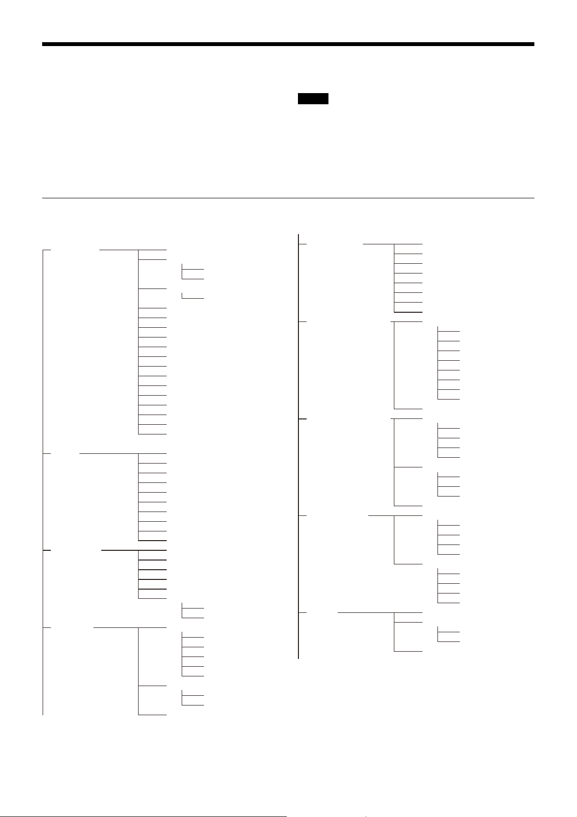
Menu List
VF DISPLAY
' ! 'IND
VF MARKER
VF DETAIL
EX
ZOOM
DISP
FORM
FORM
FOCUS
ND
CC
5600K
IRIS
WHITE
D.EXT
GAIN
SHUTTER
BATT
RETURN
TALK
MESS
FOLLOW F
AGE
ND
CC
WHITE
5600K
GAIN
SHUTTER
FAN
EXT
D.EXT
Y TALLY
MARKER
LEVEL
CENTER
SAFETY ZONE
EFFECT
ASPECT
MASK
SAFETY
VF DETAIL
CRISP
FREQUENCY
FLICKER
AREA
ZOOM LINK
COLOR DE
RETURN DISABLE
TAIL
PEAK COLOR
CHROMA LEVEL
FOCUS NAME
01 (U04)
02 (U05)
03 (U06)
04 (U02)
FOCUS ASSIST
ZEBRA
INDICATOR
MODE
LEVEL
GAIN
OFFSET
AREA MARKER
SIZE
POSITION
POSITION H
POSITION V
ZEBRA
ZEBRA1
LEVEL
WIDTH
ZEBRA2
FOCUS POSITION METER1
FOCUS POSITION METER
DYNAMIC FOCUS
NEAR LIMIT
FAR LIMIT
DIRECTION
SIZE
SENSE
NAME DISP
FRAME DISP
FRAME WIDTH
RULED LINE
MKR1
MKR2
MKR3
INDEX COLOR
INDEX WIDTH
MARKER WIDTH
DYNAMIC FOCUS
FREQUENCY
ZOOM LINK
CRISP
LEVEL
PEAK COLOR
THRESHOLD
COLOR LEVEL
CURRENT FOCUS DIST
CURRENT FOCUS DIST
MARKER CONFIG
FOCUS POSITION METER2
ADJUSTED SIGN
09 (U08)8)
08 (U03)
06
05
07
This section shows the menus to be displayed on the
viewfinder screen in tables.
• For the pages that have been registered in the USER
menu at the factory, the USER menu page numbers are
indicated in parenthesis in the No. column of the tables.
• A CONTENTS page (numbered 00) is also provided for
each menu.
Menu Tree
OPERATION menu
Notes
HDLA: HDLA1500-series Large Lens Adaptor, HDLA1507
Large Viewfinder Adaptor
CCU: HDCU5000/5500/3100/3170/3500/2000/2500
Camera Control Unit
Bold values (e.g. ON, OFF, 0): Default settings
Execute via ENTER: Execute by pushing on the MENU SEL
knob/ENTER button.
34
Page 35
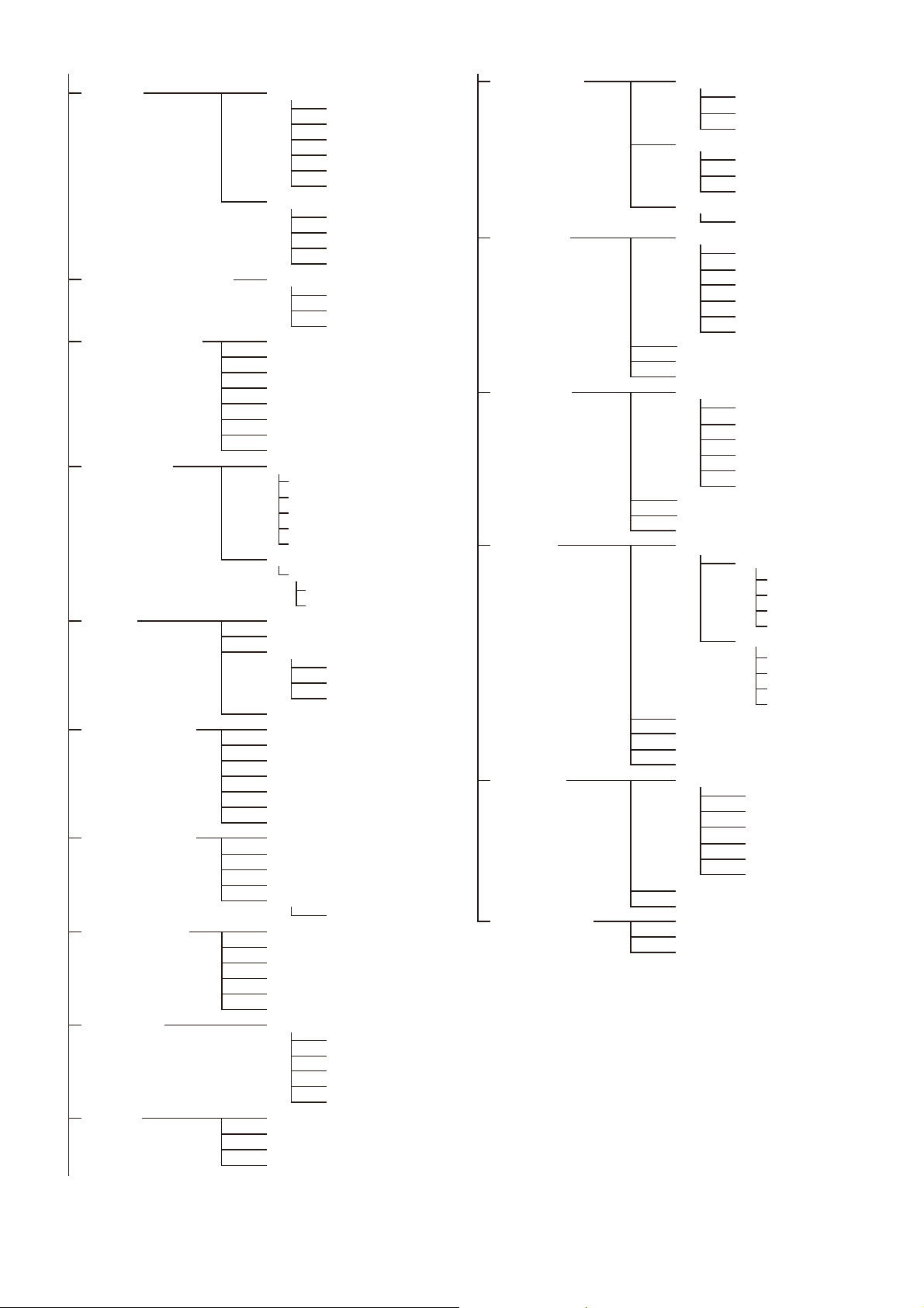
SWITCH ASSIGN2
EXT SWITCH
RETURN
LENS VTR S/S
FRONT RET1
FRONT RET2
HANDLE SW1
HANDLE SW2
B PUSH
C PUSH
A ROT
B ROT
C ROT
ZOOM SPEED
RET CTRL CONNECTOR
RET1 Pin5:
RET2 Pin6:
RET3 Pin4:
INCOM1 Pin1:
INCOM2 Pin2:
RET1 SW SEL
RET2 SW SEL
RET3 SW SEL
RET1 SW + RET2 SW
BOX CURSOR FILE
VF OUT
SWITCH ASSIGN1
1:
CURSOR CURSOR
BOX/CROSS
H POSITION
V POSITION
WIDTH
HEIGHT
BOX MEMORY
H POSI
V POSI
WIDTH
HEIGHT
LEVEL
SPIRIT LEVEL INDICATOR
MODE
REVERSE
SCALE
H POSITION
V POSITION
ANGLE
OFFSET
SET ZERO ANGLE
CLEAR
VF OUT
CHAR
2:
3:
4:
5:
STORE
READ (USB t CAM)
WRITE (CAM t USB)
ACTER LEVEL
GAIN
ASSIGNABLE
PinP
POSITION
SIZE
MODE
HFR MODE (HD)
VF ASSIGN
VF OUT SW
INSIDE RET1
INSIDE RET2
INSIDE CALL
16 (U10)
18
REAR FUNCTION
ASSIGN
17
A PUSH
19
12
14 (U01)
15 (U09)
10 (U07)
13
GAIN
FILTER
MODE
DYNAMIC CONTRAST
VF DYNAMIC CONTRAST
11
TRACKER
EARPHONE
OPERATOR FILE
RECEIVE SELECT
INPUT LEVEL
OUTPUT LEVEL L-CH
OUTPUT LEVEL 2
OUTPUT LEVEL R-CH
RECEIVE SELECT
MIX TALK
OPERATION LINK
INTERCOM
PGM1
PGM2
PGM3
TRACKER
INTERCOM
PGM1
PGM2
PGM3
SIDE TONE
READ (USB t CAM)
WRITE (CAM t USB)
PRESET
INTERCOM2
INTERCOM1/2
RECEIVE SELECT
INTERCOM
PGM1
PGM3
PGM2
TRACKER
SIDE TONE
MIX TALK
PGM3 VOLUME LINK
INTERCOM1 RECEIVE SELECT
INTERCOM
PGM1
PGM3
PGM2
TRACKER
SIDE TONE
INTERCOM1/2
MIX TALK
PGM3 VOLUME LINK
23
24
25
22
21
INTERCOM2
LEVEL
POWER
UNBAL
EARPHONE
LEVEL
HEADSET MIC
20 (U11)
INTERCOM1
LEVEL
POWER
UNBAL
[1-LR]
INTERCOM
PGM1
PGM2
PGM3
[2]
• INTERCOM and MIX TALK sub menu items are displayed
on the UCJ model only.
• On the CE model, the INTERCOM sub menu item is
replaced by separate ENG and PROD menu items. On the
UCJ model, INTERCOM is replaced by separate ENG and
PROD items, depending on the setting of the Line select
/ Receive MIX select switch.
35
Page 36
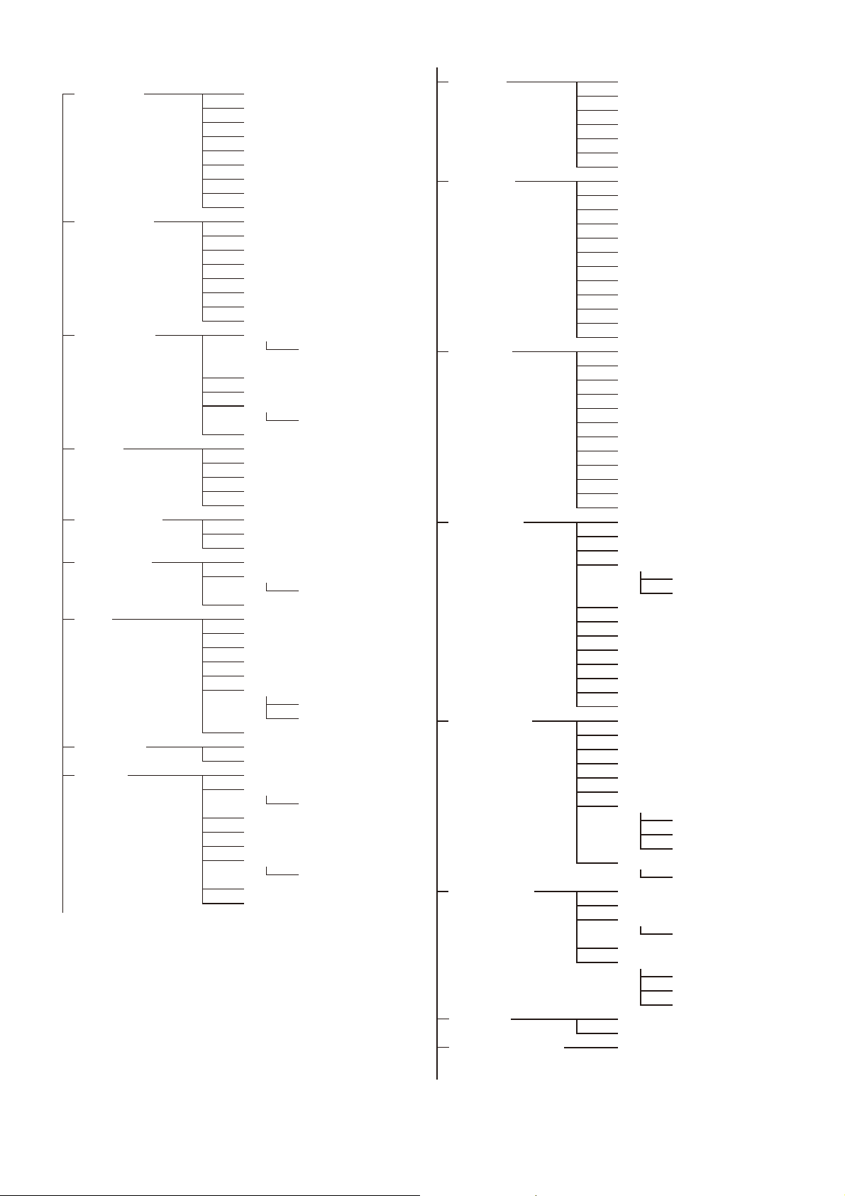
PAINT menu
SW STATUS
P01
VIDEO LEVEL
P02
COLOR TEMP
P03
GAMMA
P04
BLACK GAMMA
P05
SATURATION
P06
KNEE
P07
WHITE CLIP
P08
DETAIL 1
P09
FLARE
GAMMA
BLK GAM
KNEE
WHT CLIP
DETAIL
LVL DEP
SKIN DTL
MATRIX
WHITE
BLACK
FLARE
GAMMA
V MOD
FLARE
V MOD
TEST
WHITE
AUTO WHITE
AT W
SPEED
BALANCE
COLOR TEMP
BALANCE
MASTER
LEVEL
COARSE
TABLE
GAMMA
TEST
LEVEL
RANGE
TEST
SATURATION
LOW KEY SAT
RANGE
TEST
K POINT
K SLOPE
KNEE
KNEE MAX
KNEE SAT
AUTO KNEE
POINT LIMIT
SLOPE
W CLIP
ABS
DETAIL
LEVEL
LIMITER M
LIMITER WHT
LIMITER BLK
CRISP
HFR RATIO
HFR RATIO
LEVEL DEPEND
ABS
ABS
DETAIL 2
P10
SKIN DETAIL
P13
USER MATRIX
P14
MULTI MATRIX
P15
H/V RATIO
FREQ
MIX RATIO
KNEE APT
DTL H/V MODE
INDEPENDENT
ABS
HD DETAIL
P11
DETAIL
LEVEL
LIMITER M
LIMITER WHT
LIMITER BLK
CRISP
LEVEL DEPEND
H/V RATIO
FREQ
MIX RATIO
KNEE APT
ABS
4K DETAIL
P12
DETAIL
LEVEL
LIMITER M
LIMITER WHT
LIMITER BLK
CRISP
LEVEL DEPEND
H/V RATIO
FREQ
MIX RATIO
KNEE APT
ABS
SKIN DTL
SKIN GATE
NATURAL SKINDTL
ZOOM LINK
TELE
WIDE
CH SW
HUE
PHASE
WIDTH
SAT
LEVEL
R-G
R-B
G-R
G-B
B-R
B-G
MATRIX
PRESET
LEVEL
USER
MULTI
ADAPTIVE MATRIX
PHASE
HUE
SAT
ALL CLEAR
GATE
MATRIX
PRESET
USER
MULTI
Y LIMIT
ABS
SHUTTER
P16
NOISE SUPPRESSION
P17
SHUTTER
ECS FREQ
SUPPRESSION
36
Page 37
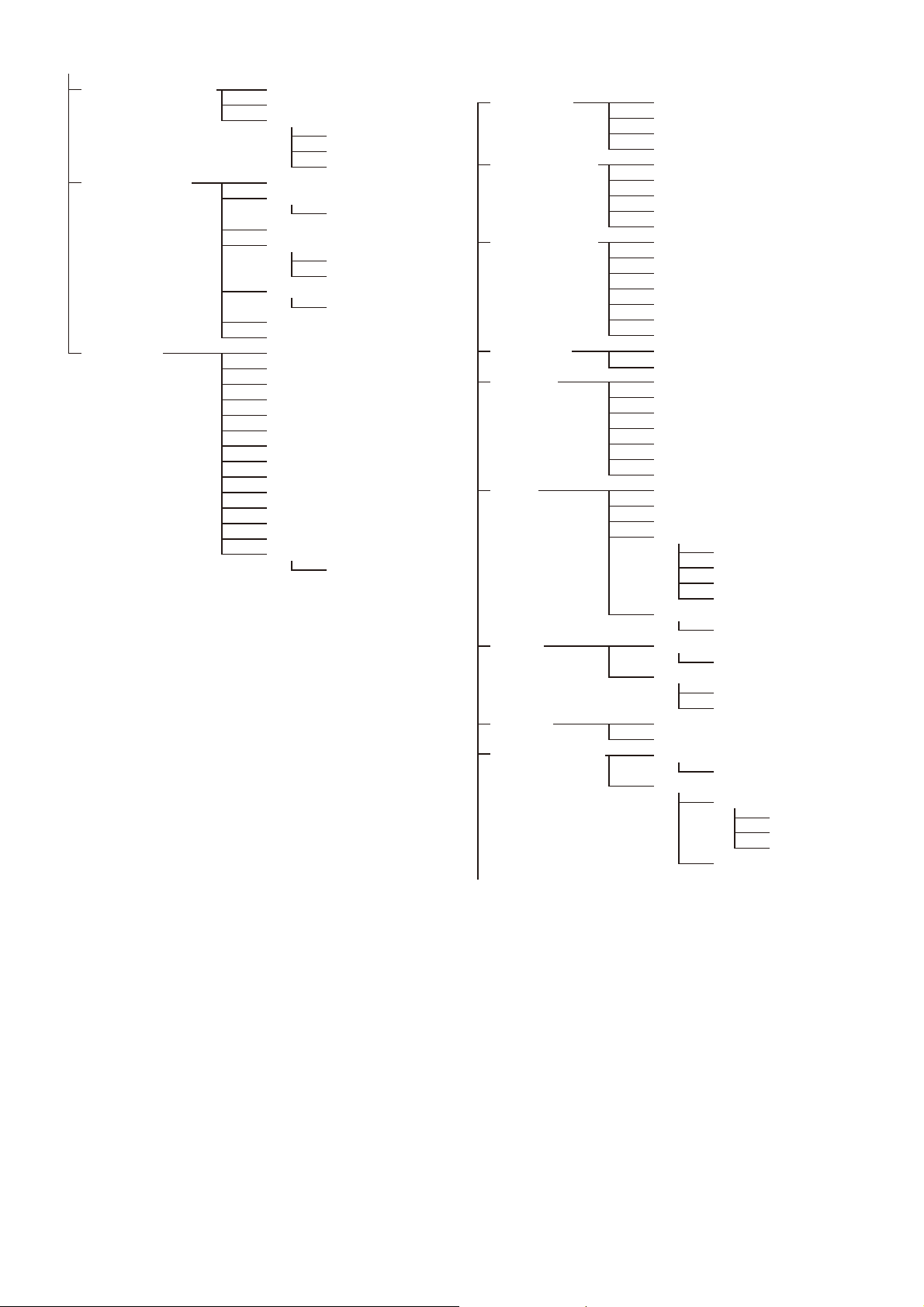
MAINTENANCE menu
SCENE FILE
P20
1
2
3
4
5
STORE
STANDARD
READ (USB t CAM)
WRITE (CAM t USB)
FILE ID
CAM CODE
DATE
HDR OPERATION
P19
HDR CONTRAST
HDR MODE
FLICKER REDUCTION
P18
REDUCTION
SDR GAIN
POWER LINE FREQUENCY
MODE
GAIN
OFFSET
ACM TYPE
POINT
SLOPE
HDR KNEE
HDR BLACK OFFSET
LEVEL
HDR WHITE CLIP
HDR BLACK CLIP
HDR BLACK COMPRESSION
DISSOLVE
01
SPEED
AUTO SETUP
M01
WHITE SHADING
M02
BLACK SHADING
M03
OHB MATRIX
M04
AUTO IRIS
M05
MIC GAIN
M08
CAMERA NUMBER
M09
AUTO BLACK
AUTO WHITE
AUTO LEVEL
TEST
V SAW
V PARA
H SAW
H PARA
WHITE
V SAW
V PARA
H SAW
H PARA
BLK SET
BLACK
MASTER GAIN
OHB MATRIX
MATRIX
AUTO IRIS
WINDOW
OVERRIDE
IRIS LEVEL
APL RATIO
IRIS GAIN
IRIS CLOSE
MIC1
MIC2
LENS1
M06
F NO. DISP
AL
AF DISPLAY
LENS2
FOLLOW FOCUS
F DROP COMP
REMOTE CONTROL
AC
MAX GAIN
GAIN LIMIT
DROP POINT
OFFSET ADJUST SENS
CONTROL MODE
OFFSET CANCEL GAIN
OUTSIDE DISPLAY
CAMERA NUMBER
CAMERA NUMBER
CCU LINK
X
ROUNDNESS
STORE LENS FILE
ARIA
Y
SIZE
BACK GROUND
M07
37
Page 38
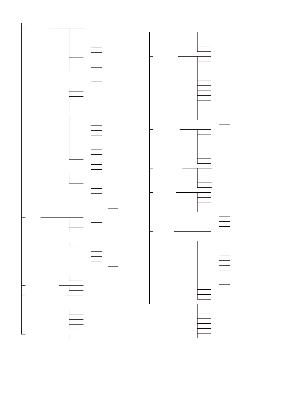
FILE menu
TEST OUT
M12 (U13)
SDI OUT
M13 (U14)
TRUNK
M14
GENLOCK
M15
DATE
M16
BATTERY ALARM
M17
SIMPLE PROTOCOL
M18
OTHERS
M19
OPTION KEY
M20
OUTPUT
VBS-OUT
CHARACTER
GAIN
CH
SETUP
ROMA
DOWN CONVERTER
SELECT
ASPECT
SDI-1
SDI-2
SDI-MONI OUT
CHARACTER
EMB AUDIO
DOWN
CONVERTER
SELECT
ASPECT
TRUNK
INTERFACE
AUX REMOTE
NETWORK TRUNK
LINK
REFERENCE
GENLOCK
S
PORT
TATUS
FORMAT
PHASE
V
BAUDRATE
H
DATE/TIME
DATE FORMAT
BEFORE END
END
TRANSPORT CONVERTER MODE
FAN MODE
CAM BARS
WHITE SETUP MODE
READ (USB t CAM)
EFFECTIVE FUNCTION
OUTPUT FORM
M11 (U12)
CURRENTAT
STANDALONE PAINT SWITCH
HD DOWNCONV FILTER
CALL/TALLY
M10
CCU CALL
CAM CALL
HDLA UP TALLY
NUMBER DISPLAY
RESOLUTION
FREQUENCY
BIT DEPTH
COLOR
OETF
MODE
BRIGHTNESS
OUTSIDE LED
EXTENDER
FILTER DISC
TALLY GUARD
SYNC-OUT
V-PHASE
H-PHASE
TALLY BRIGHTNESS
NUMBER BRIGHTNESS
OPERATOR FILE
F01
SCENE FILE
F02
REFERENCE
F03
LENS FILE
F05
OHB FILE
F06
READ (USB t CAM)
WRITE (CAM t USB)
PRESET
S
CLEAR PRESET FILE
TORE PRESET FILE
1
2
3
4
5
01
STORE
STANDARD
READ (USB t CAM)
WRITE (CAM t USB)
FILE ID
CAM CODE
DATE
STORE FILE
STANDARD
ALL PRESET
DISSOLVE
SPEED
READ (USB
t
BOX CURSOR FILE
F08
1:
2:
3:
4:
5:
STORE
READ (USB t CAM)
WRITE (CAM t USB)
CAM)
WRITE (CAM t USB)
FILE ID
CAM CODE
DATE
STORE FILE
No.
NAME
F NO
CENTER MARKER
H POS
V POS
STORE
STORE FILE
MATRIX FILE
F07
1
2
3
4
5
CLEAR ALL
CUSTOM PRESET MATRIX
READ (USB t CAM)
WRITE (CAM t USB)
FILE ID
CAM CODE
DATE
STORE FILE
USER GAMMA
F04
READ (USB t CAM)
PRESET
FILE ID
CAM CODE
DATE
38
Page 39
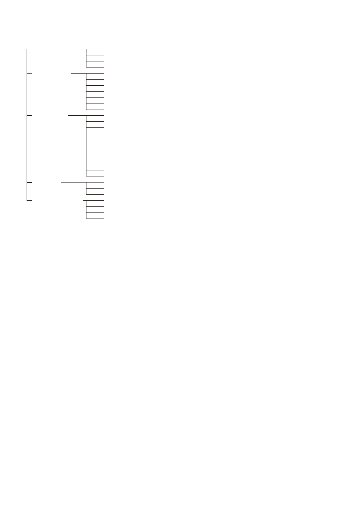
DIAGNOSIS menu
EFFECTIVE FUNCTION
CABLE LENGTH
CABLE MARGIN
CAM INPUT VOLTAGE
CAM CONSUMPTION
OPTICAL LEVEL
D01
BOARD STATUS
D02
ROM VERSION
D03 (U15)
SERIAL NO.
D04
POWER SUPPLY STATUS
D05
CCU t CAM
CAM
REFLECTION
t
CCU
OHB
DPR
SY
PS
TX
CD
1)
HOURS METER
CAMERA APP
OS
UPDATER
SY
PANEL
DPR
PS
TX
CD1
1)
CD2
1)
TR
1)
MODEL
NO.
CABLE LENGTH
1)
When the HKC-TR37 is installed
39
Page 40
OPERATION Menu
OPERATION
Page name
Page No.
<VF DISPLAY>
01 (U04)
<‘!’ IND>
02 (U05)
Item Settings Description
EX ON
ZOOM ON, OFF
DISP LEFT
FORM 999
FOCUS ON, OFF
FORM 999
ND ON
CC ON
5600K ON
IRIS ON
WHITE ON, OFF
D.EXT ON
GAIN ON
SHUTTER ON
BATT ON, OFF
RETURN ON
TALK ON
MESSAGE ALL
FOLLOW F ON, OFF
FOCUS NAME OFF, 1S, 3S, 5S, ON
ND ON
CC ON
WHITE ON
5600K ON
GAIN ON, OFF, ---
SHUTTER ON
FAN ON, OFF
EXT ON
D.EXT ON
Y TALLY ON
, OFF, 3S
, 3S
, RIGT
, mm
, 3S Valid only when a serial lens is used.
, m, ft
, OFF, 3S
, OFF, 3S
, OFF, 3S
, OFF, 3S
, 3S
, OFF, 3S
, OFF, 3S
, OFF, 3S
, 3S
, OFF, 3S
, OFF, 3S
, WRN, AT, OFF ALL: Displays all messages.
WRN: Displays warning messages and higher.
AT: Displays Auto Setup messages and higher.
, 3S
Sets whether to show/hide the marker name and
sets the display time.
, OFF [IND]: Turns the ‘!’ display area
, 2, 3, 4, 5 (combination
1
allowed)
, OFF
, C, D (combination allowed)
A, B
, OFF, ---
, B (combination allowed)
P, A
, OFF, ---
ON, OFF
, M, H (combination allowed)
L
, OFF, ---
ON, OFF
, AUTO2, MIN, MAX
AUTO1
, OFF
, OFF
, OFF
[NORMAL]: Specifies the conditions under which the
‘!’ indication is not to be displayed even if [IND] is
ON. (By specifying the standard or normal
conditions here, non-standard or abnormal
conditions can be found with the ‘!’ indication on
the viewfinder screen.)
Example: With the default setting of ND, the ‘!’
indication is displayed when an ND filter other
than 1 is selected.
---: When a CCU is connected (cannot be changed)
(see page 28)
on/off.
40
Page 41
OPERATION
Page name
Item Settings Description
Page No.
<VF MARKER>
03 (U06)
MARKER ON
WHITE
LEVEL MIN, 1 to 10, 4
CENTER ON, OFF
1, 2, 3, 4 1: Full cross
SAFETY ZONE ON, OFF
80.0, 90.0, 92.5, 95.0%
EFFECT ON, OFF
ASPECT ON, OFF
16:9, 15:9, 14:9, 13:9, 4:3 (4.3): If VF SCAN is set to 4:3 when HDLA is attached
MASK ON, OFF
0 to 15, 12
SAFETY ON, OFF
80.0, 90.0
<VF DETAIL>
04 (U02)
VF DETAIL ON
0 to 100%, (0 to 100%), 25%
CRISP –99 to +99, 0
FREQUENCY 9M, 14M, 18M
FLICKER ON, OFF
AREA 10 to 100%, 100%
ZOOM LINK ON, OFF
0 to 100%, 50%
COLOR DETAIL ON, OFF
YELLOW, RED, BLUE
PEAK COLOR ON, OFF
CHROMA LEVEL 100%, 50%, 25%, 0%
RETURN DISABLE ON, OFF
<DYNAMIC FOCUS>05DYNAMIC FOCUS OFF
FREQUENCY EXTRA-LOW
(AUTO)
ZOOM LINK ON, OFF
MODE1, MODE2, MODE3,
MODE4
0 to 100%, 50%
(5% increments)
CRISP 0 to 99, 6
LEVEL LOW
VERY-HIGH
PEAK COLOR OFF, RED, BLUE, GREEN,
BROWN, PURPLE, YELLOW
THRESHOLD 0 to 99, 50 Sets the threshold level for adding color specified
COLOR LEVEL 0 to 99, 19
, OFF Sets the display of all markers on/off.
, BLACK, DOT
2: Full cross with a hole
3: Center
4: Center with a hole
(cannot be changed)
(ON): If VF SCAN is set to 4:3 when HDLA is attached
(cannot be changed)
Sets the darken level outside the aspect area.
For the safety marker in Aspect mode.
, 92.5, 95.0%
, OFF, (ON), (OFF) Settings in ( ): When HDLA is attached (cannot be
changed)
Selects whether to set VF DETAIL to OFF for RETURN
display.
, ON, (OFF) (OFF): Displayed for formats other than 4K/HDR
format.
, LOW, MID, HIGH,
Sets the bandwidth of the 4K resolution highfrequency signal to detect.
(AUTO): Displayed when ZOOM LINK is set to ON.
Sets characteristics according to the zoom position.
Sets the level at the WIDE position mark.
Adjust to eliminate minute components of the
detected signal.
, MIDDLE, HIGH,
Sets the brightness level of the marking signal.
using PEAK COLOR.
Sets the saturation of the color of the PEAK COLOR
indicator.
41
Page 42
OPERATION
Page name
Page No.
<FOCUS POSITION
METER1>
06
<FOCUS POSITION
METER2>
07
<FOCUS ASSIST>
08 (U03)
Item Settings Description
FOCUS POSITION METER OFF
NEAR LIMIT 0
FAR LIMIT 0 to 999
DIRECTION HORIZONTAL
SIZE NORMAL
RULED LINE OFF
INDEX COLOR BLACK, WHITE
INDEX WIDTH 1
MARKER WIDTH 1
CURRENT FOCUS DIST Displays the current focus distance (display only).
ADJUSTED SIGN
SENSE 1 to 5, 2
NAME DISP OFF, 1S, 3S, 5S, ON
FRAME DISP OFF, 1S, 3S, 5S, ON
FRAME WIDTH 1 to 5, 2
MARKER CONFIG
[REG] MKR1, 2, 3 Execute using ENTER. Registers a marker at the current focus position.
[DISP] MKR1, 2, 3 OFF
[COLOR] MKR1, 2, 3 RED
[NAME] MKR1, 2, 3 Max. 8 characters
[POS] MKR1, 2, 3 0 to 999 Sets the position of the marker.
CURRENT FOCUS DIST Displays the current focus distance (display only).
INDICATOR ON, OFF
MODE BOX, B&W, COL
LEVEL MIN, 1 to 10, 4
GAIN 0 to 99, 50
OFFSET 0 to 99, 50
AREA MARKER ON, OFF
SIZE SMALL, MIDDLE, LARGE
POSITION LEFT, CENTER
POSITION H 0 to 99, 50
POSITION V 0 to 99, 50
, ON Shows/hides the focus position meter.
to 999 Sets the NEAR edge of the focus position meter.
Sets the FAR edge of the focus position meter.
, VERTICAL Sets the display direction of the focus position
, HALF Sets the display size of the focus position meter.
, ON Shows/hides ruled lines.
to 5 Sets the index width.
to 9 Sets the width of the marker axis portion.
, ON Shows/hides markers.
, GREEN, BLUE, YELLOW,
ORANGE, PURPLE, GRAY,
BLACK, WHITE
(Default value: MARKER 1 to 3)
, LEFT, TOP, RIGHT
BTM
QUICK, SMOOTH
, RIGHT
meter.
HORIZONTAL: Horizontal display at the top of the
screen.
VERTICAL: Vertical display along the right edge of
the screen.
Sets the index color.
Sets the adjustment sensitivity.
Increasing the value increases the sensitivity.
Sets whether to show/hide the marker name and
sets the display time.
Sets whether to show/hide the adjustment frame
and sets the display time.
Sets the width of the adjustment frame.
(Cannot be registered here if marker registration has
been assigned to a dedicated switch.)
(Cannot be changed here if marker registration has
been assigned to a dedicated switch.)
Sets the color of the triangular part of the marker.
Sets the text of the marker name.
See “To specify a character string” (page 30).
42
Page 43
OPERATION
Page name
Page No.
<ZEBRA>
09 (U08)
<CURSOR>
10 (U07)
<VF DYNAMIC
CONTRAST>
11
<BOX CURSOR FILE>121: BOX CURSOR FILE selection FILE name input.
<SPIRIT LEVEL>
13
Item Settings Description
ZEBRA ON, OFF
1, 2, 1&2
ZEBRA1
LEVEL 50 to 109%, 70%
WIDTH 0 to 30%, 10%
ZEBRA2 50 to 109%, 100%
CURSOR ON, OFF Displayed only if HDLA attached.
LEVEL WHITE
BOX/CROSS BOX, CROSS
H POSITION 0 to 99, 50
V POSITION 0 to 99, 50
WIDTH 0 to 99, 50
HEIGHT 0 to 99, 50
BOX MEMORY 1/2/3: OFF, ON
H POSI 1/2/3: 0 to 99, 50
V POSI 1/2/3: 0 to 99, 50
WIDTH 1/2/3: 0 to 99, 50
HEIGHT 1/2/3: 0 to 99, 50
DYNAMIC CONTRAST ON, OFF, (OFF) (OFF) is displayed when CAM BARS is set to ON.
GAIN 0 to 100%, 30%
FILTER NARROW, MIDDLE, WIDE
MODE LINEAR, HIGHLIGHT
2:
3:
4:
5:
STORE Stores a BOX CURSOR FILE name in the camera.
READ (USB t CAM) Transfers a BOX CURSOR FILE from a USB drive to
WRITE (CAM t USB) Transfers a BOX CURSOR FILE from the camera to a
INDICATOR ON, OFF
MODE 1, 2 Switches the display method of the indicator.
REVERSE OFF
SCALE 50% to 150%, 100%
H POSITION 0 to 99, 50
V POSITION 0 to 99, 97
ANGLE Displays the inclination angle (display only).
OFFSET –90 to +90, 0
SET ZERO ANGLE Execute using ENTER. Designates the current angle as level (0°).
CLEAR Execute using ENTER. Sets OFFSET to 0.
, BLACK, DOT
MIN, 1 to 10, 4
Displayed only if HDLA attached.
, FOGGY
Align the cursor to the left of the number to select
the BOX CURSOR FILE.
Align the cursor to the right of the number to enter
the BOX CURSOR FILE name.
“To specify a character string” (page 30)
See
the camera.
USB drive.
, ON Inverts the movement of the indicator horizontally.
Adjusts the horizontal width of the indicator.
.
43
Page 44
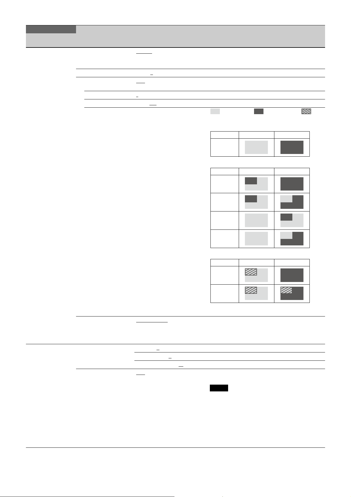
OPERATION
PinP: OFF
PinP: RETURN
PinP: HD PROMPTER
Mode RET SW OFF RET SW ON
---
Mode RET SW OFF RET SW ON
1
2
3
4
Mode RET SW OFF RET SW ON
1
2
Page name
Page No.
<VF OUT>
14 (U01)
Item Settings Description
VF OUT COLOR
CHARACTER LEVEL 1 to 5, 4
PinP OFF, RETURN, HD PROMPTER OFF and RETURN displayed only when the HKC-TR37
POSITION 1
SIZE 1/2.5, 1/3
MODE PinP OFF: ---
, Y, R, G, B,
(COLOR), (Y), (R), (G), (B), (RET),
(R+G), (R+B), (G+B)
, 2, 3, 4
, 1/4
PinP RETURN: 1, 2, 3, 4
PinP HD PROMPTER: 1, 2
Settings in ( ): When HDLA is attached (cannot be
changed)
is installed.
: Main picture, : Return picture, : HD
Prompter picture
<SWITCH ASSIGN1>
15 (U09)
*1: See
*1
page 53
.
HFR MODE (HD) ACCUMULATE
GAIN L: –6, –3, 0
M: –6, –3, 0, 3, 6
H: –6, –3, 0, 3, 6, 9, 12
ASSIGNABLE OFF
SW, RETURN3 SW, INCOM1,
INCOM2, EXTENDER,
D.EXTENDER, 5600K, VF DETAIL,
SPIRIT LEVEL INDICATOR, FOCUS
ASSIST INDICATOR, PinP, VF
ASSIGN SW1, VF ASSIGN SW2,
RET1 SW TOGGLE, RET2 SW
TOGGLE, RET3 SW TOGGLE, VTR
S/S, TALLY R, TALLY G, TALLY Y,
FAN MAX, CURSOR ALL OFF,
FLAG, AWB, CALL, ZOOM(T),
ZOOM(W)
, 3, 6, 9, 12 dB
, RETURN1 SW, RETURN2
Cannot be used during standalone operation.
, SINGLE Output images as follows to the viewfinder when in
HD HFR format.
ACCUMULATE: Accumulated image
SINGLE: Single image
, 9, 12 dB
dB
When HDLA is attached: OFF, EXTENDER, 5600K,
FAN MAX, D.EXTENDER, PinP, FLAG
Notes
• When you turn D.EXTENDER ON or OFF, noise may
be generated. This is not a malfunction.
D.EXTENDER does not operate when 4K or 2×
speed format is selected.
• TALLY R, TALLY G, TALLY Y are displayed only in
standalone operation.
• INCOM1 and INCOM2 are displayed on the UCJ
model only. ENG and PROD are displayed instead
on the CE model.
44
Page 45
OPERATION
Page name
Page No.
<SWITCH ASSIGN1>
*1
15 (U09)
*1: See
page 53
.
Item Settings Description
VF ASSIGN OFF, RETURN1 SW, RETURN2
VF OUT SW VF OUT RGB
INSIDE RET1 OFF, RETURN1 SW
INSIDE RET2 OFF, RETURN1 SW, RETURN2
INSIDE CALL OFF, RETURN1 SW, RETURN2
SW, RETURN3 SW, INCOM1,
INCOM2, EXTENDER,
D.EXTENDER, 5600K, VF DETAIL,
SPIRIT LEVEL INDICATOR, FOCUS
ASSIST INDICATOR, PinP, VF
ASSIGN SW1, VF ASSIGN SW2,
RET1 SW TOGGLE, RET2 SW
TOGGLE, RET3 SW TOGGLE, VTR
S/S, TALLY R, TALLY G, TALLY Y,
FAN MAX, CURSOR ALL OFF,
FLAG, AWB, CALL, ZOOM(T),
ZOOM(W)
METER
SW, RETURN3 SW, INCOM1,
INCOM2, EXTENDER,
D.EXTENDER, 5600K, VF DETAIL,
SPIRIT LEVEL INDICATOR, FOCUS
ASSIST INDICATOR, PinP, VF
ASSIGN SW1, VF ASSIGN SW2,
RET1 SW TOGGLE, RET2 SW
TOGGLE, RET3 SW TOGGLE, VTR
S/S, TALLY R, TALLY G, TALLY Y,
FAN MAX, CURSOR ALL OFF,
FLAG, AWB, CALL, ZOOM(T),
ZOOM(W)
SW, RETURN3 SW, INCOM1,
INCOM2, EXTENDER,
D.EXTENDER, 5600K, VF DETAIL,
SPIRIT LEVEL INDICATOR, FOCUS
ASSIST INDICATOR, PinP, VF
ASSIGN SW1, VF ASSIGN SW2,
RET1 SW TOGGLE, RET2 SW
TOGGLE, RET3 SW TOGGLE, VTR
S/S, TALLY R, TALLY G, TALLY Y,
FAN MAX, CURSOR ALL OFF,
FLAG, AWB, CALL, ZOOM(T),
ZOOM(W)
SW, RETURN3 SW, INCOM1,
INCOM2, EXTENDER,
D.EXTENDER, 5600K, VF DETAIL,
SPIRIT LEVEL INDICATOR, FOCUS
ASSIST INDICATOR, PinP, VF
ASSIGN SW1, VF ASSIGN SW2,
RET1 SW TOGGLE, RET2 SW
TOGGLE, RET3 SW TOGGLE, VTR
S/S, TALLY R, TALLY G, TALLY Y,
FAN MAX, CURSOR ALL OFF,
FLAG, AWB, CALL
ZOOM(W)
, FOCUS POSITION
, RETURN2
, ZOOM(T),
Displayed only when HDLA is attached.
Note
INCOM1 and INCOM2 are displayed on the UCJ
model only. ENG and PROD are displayed instead on
the CE model.
Displayed only when HDLA is attached.
(When set to FOCUS POSITION METER, VF OUT SW
(R/G/B) can be used to register/display marker
1/2/3.)
Assigns functions executed when you press the RET
1 button.
Note
INCOM1 and INCOM2 are displayed on the UCJ
model only. ENG and PROD are displayed instead on
the CE model.
Assigns functions executed when you press the RET
2 button.
Note
INCOM1 and INCOM2 are displayed on the UCJ
model only. ENG and PROD are displayed instead on
the CE model.
Assigns functions executed when you press the
CALL button.
Note
INCOM1 and INCOM2 are displayed on the UCJ
model only. ENG and PROD are displayed instead on
the CE model.
45
Page 46
OPERATION
Page name
Page No.
<SWITCH ASSIGN2>
*1
16 (U10)
*1: See
page 53
.
Item Settings Description
LENS VTR S/S OFF, RETURN1 SW, RETURN2
FRONT RET1 OFF, RETURN1 SW
FRONT RET2 OFF, RETURN1 SW, RETURN2
HANDLE SW1 OFF, RETURN1 SW
HANDLE SW2 OFF, RETURN1 SW, RETURN2
ZOOM SPEED 0 to 99, 20
SW, RETURN3 SW, INCOM1,
INCOM2, EXTENDER,
D.EXTENDER, 5600K, VF DETAIL,
SPIRIT LEVEL INDICATOR, FOCUS
ASSIST INDICATOR, PinP, VF
ASSIGN SW1, VF ASSIGN SW2,
RET1 SW TOGGLE, RET2 SW
TOGGLE, RET3 SW TOGGLE, VTR
S/S, TALLY R, TALLY G, TALLY Y,
FAN MAX, CURSOR ALL OFF,
FLAG, AWB, CALL, ZOOM(T),
ZOOM(W)
, RETURN2
SW, RETURN3 SW, INCOM1,
INCOM2, EXTENDER,
D.EXTENDER, 5600K, VF DETAIL,
SPIRIT LEVEL INDICATOR, FOCUS
ASSIST INDICATOR, PinP, VF
ASSIGN SW1, VF ASSIGN SW2,
RET1 SW TOGGLE, RET2 SW
TOGGLE, RET3 SW TOGGLE, VTR
S/S, TALLY R, TALLY G, TALLY Y,
FAN MAX, CURSOR ALL OFF,
FLAG, AWB, CALL, ZOOM(T),
ZOOM(W)
SW, RETURN3 SW, INCOM1,
INCOM2, EXTENDER,
D.EXTENDER, 5600K, VF DETAIL,
SPIRIT LEVEL INDICATOR, FOCUS
ASSIST INDICATOR, PinP, VF
ASSIGN SW1, VF ASSIGN SW2,
RET1 SW TOGGLE, RET2 SW
TOGGLE, RET3 SW TOGGLE, VTR
S/S, TALLY R, TALLY G, TALLY Y,
FAN MAX, CURSOR ALL OFF,
FLAG, AWB, CALL, ZOOM(T),
ZOOM(W)
, RETURN2
SW, RETURN3 SW, INCOM1,
INCOM2, EXTENDER,
D.EXTENDER, 5600K, VF DETAIL,
SPIRIT LEVEL INDICATOR, FOCUS
ASSIST INDICATOR, PinP, VF
ASSIGN SW1, VF ASSIGN SW2,
RET1 SW TOGGLE, RET2 SW
TOGGLE, RET3 SW TOGGLE, VTR
S/S, TALLY R, TALLY G, TALLY Y,
FAN MAX, CURSOR ALL OFF,
FLAG, AWB, CALL, ZOOM(T),
ZOOM(W)
SW, RETURN3 SW, INCOM1
INCOM2, EXTENDER,
D.EXTENDER, 5600K, VF DETAIL,
SPIRIT LEVEL INDICATOR, FOCUS
ASSIST INDICATOR, PinP, VF
ASSIGN SW1, VF ASSIGN SW2,
RET1 SW TOGGLE, RET2 SW
TOGGLE, RET3 SW TOGGLE, VTR
S/S, TALLY R, TALLY G, TALLY Y,
FAN MAX, CURSOR ALL OFF,
FLAG, AWB, CALL, ZOOM(T),
ZOOM(W)
Assigns a function to the VTR START/STOP switch
on the mounted lens.
Note
INCOM1 and INCOM2 are displayed on the UCJ
model only. ENG and PROD are displayed instead on
the CE model.
VTR S/S is available only when using the camera as
a standalone device, and adds the REC signal to the
SDI signal. Pressing this button repeatedly, toggles
recording on/off. While recording, the tally lamp
lights in red.
Note
INCOM1 and INCOM2 are displayed on the UCJ
model only. ENG and PROD are displayed instead on
the CE model.
,
46
Page 47
OPERATION
Page name
Page No.
<REAR FUNCTION
ASSIGN>
17
Item Settings Description
A PUSH OFF, RETURN1 CAM SW
B PUSH
C PUSH
RETURN1 CAM SW TOGGLE,
RETURN2 CAM SW
, RETURN2
CAM SW TOGGLE, RETURN3
CAM SW, RETURN3 CAM SW
TOGGLE, VF DETAIL, FOCUS
POSITION METER, FOCUS
POSITION METER MKR1 REG,
,
Assigns functions executed when you press RET/
ASSIGNABLE buttons A, B, and C.
Default values:
When A PUSH is selected: RETURN1 CAM SW. When
B PUSH is selected: RETURN2 CAM SW. When C
PUSH is selected: RETURN3 CAM SW.
FOCUS POSITION METER MKR2
REG, FOCUS POSITION METER
MKR3 REG, FOCUS ASSIST
INDICATOR, DIGITAL EXTENDER,
VF DYNAMIC CONTRAST,
DYNAMIC FOCUS
A ROT OFF, RET CCU CH SEL
B ROT
LEVEL, VF DETAIL CRISP, FOCUS
ASSIST IND GAIN
C ROT
, VF DETAIL
Assigns functions executed when you turn RET/
ASSIGNABLE buttons A, B, and C.
The items that can be selected vary depending on
the A PUSH, B PUSH, and C PUSH settings.
When the PUSH function is OFF: OFF
When RETURN1 CAM SW, RETURN1 CAM SW TOGGLE,
RETURN2 CAM SW, RETURN2 CAM SW TOGGLE,
RETURN3 CAM SW, RETURN3 CAM SW TOGGLE,
FOCUS POSITION METER, FOCUS POSITION METER
MKR1 REG, FOCUS POSITION METER MKR2 REG,
FOCUS POSITION METER MKR3 REG, DIGITAL
EXTENDER is selected: RET CCU CH SEL
When VF DETAIL is selected: VF DETAIL LEVEL or VF
DETAIL CRISP
When FOCUS ASSIST INDICATOR is selected: FOCUS
ASSIST IND GAIN
When VF DYNAMIC CONTRAST is selected: DYNAMIC
CONTRAST GAIN
When DYNAMIC FOCUS is selected: DYNAMIC FOCUS
CRISP
47
Page 48

OPERATION
Page name
Page No.
<EXT SWITCH>
*1
18
*1: See
page 53
Item Settings Description
RET CTRL CONNECTOR
RET1 Pin5: OFF, RETURN1 SW
, RETURN2
SW, RETURN3 SW, INCOM1,
.
INCOM2, EXTENDER,
D.EXTENDER, 5600K, VF DETAIL,
SPIRIT LEVEL INDICATOR, FOCUS
ASSIST INDICATOR, PinP, VF
ASSIGN SW1, VF ASSIGN SW2,
RET1 SW TOGGLE, RET2 SW
TOGGLE, RET3 SW TOGGLE, VTR
S/S, TALLY R, TALLY G, TALLY Y,
FAN MAX, CURSOR ALL OFF,
DYNAMIC FOCUS, FLAG, AWB,
CALL, ZOOM(T), ZOOM(W),
DYNAMIC CONTRAST
RET2 Pin6: OFF, RETURN1 SW, RETURN2
SW, RETURN3 SW, INCOM1,
INCOM2, EXTENDER,
D.EXTENDER, 5600K, VF DETAIL,
SPIRIT LEVEL INDICATOR, FOCUS
ASSIST INDICATOR, PinP, VF
ASSIGN SW1, VF ASSIGN SW2,
RET1 SW TOGGLE, RET2 SW
TOGGLE, RET3 SW TOGGLE, VTR
S/S, TALLY R, TALLY G, TALLY Y,
FAN MAX, CURSOR ALL OFF,
DYNAMIC FOCUS, FLAG, AWB,
CALL, ZOOM(T), ZOOM(W),
DYNAMIC CONTRAST
RET3 Pin4: OFF, RETURN1 SW, RETURN2
SW, RETURN3 SW
, INCOM1,
INCOM2, EXTENDER,
D.EXTENDER, 5600K, VF DETAIL,
SPIRIT LEVEL INDICATOR, FOCUS
ASSIST INDICATOR, PinP, VF
ASSIGN SW1, VF ASSIGN SW2,
RET1 SW TOGGLE, RET2 SW
TOGGLE, RET3 SW TOGGLE, VTR
S/S, TALLY R, TALLY G, TALLY Y,
FAN MAX, CURSOR ALL OFF,
DYNAMIC FOCUS, FLAG, AWB,
CALL, ZOOM(T), ZOOM(W),
DYNAMIC CONTRAST
INCOM1 Pin1: OFF, RETURN1 SW, RETURN2
SW, RETURN3 SW, INCOM1
,
INCOM2, EXTENDER,
D.EXTENDER, 5600K, VF DETAIL,
SPIRIT LEVEL INDICATOR, FOCUS
ASSIST INDICATOR, PinP, VF
ASSIGN SW1, VF ASSIGN SW2,
RET1 SW TOGGLE, RET2 SW
TOGGLE, RET3 SW TOGGLE, VTR
S/S, TALLY R, TALLY G, TALLY Y,
FAN MAX, CURSOR ALL OFF,
DYNAMIC FOCUS, FLAG, AWB,
CALL, ZOOM(T), ZOOM(W),
DYNAMIC CONTRAST
INCOM2 Pin2: OFF, RETURN1 SW, RETURN2
SW, RETURN3 SW, INCOM1,
INCOM2
, EXTENDER,
D.EXTENDER, 5600K, VF DETAIL,
SPIRIT LEVEL INDICATOR, FOCUS
ASSIST INDICATOR, PinP, VF
ASSIGN SW1, VF ASSIGN SW2,
RET1 SW TOGGLE, RET2 SW
TOGGLE, RET3 SW TOGGLE, VTR
S/S, TALLY R, TALLY G, TALLY Y,
FAN MAX, CURSOR ALL OFF,
DYNAMIC FOCUS, FLAG, AWB,
CALL, ZOOM(T), ZOOM(W),
DYNAMIC CONTRAST
This function works when each pin of the RET CTRL
connector contacts with GND (pin 3).
TALLY R, TALLY G, TALLY Y are available only when
using the camera as a standalone device, and make
the tally lamp light. VTR S/S is available only when
using the camera as a standalone device, and
makes the R tally lamp light.
VTR S/S signal is embedded in the video.
Note
INCOM1 and INCOM2 are displayed on the UCJ
model only. ENG and PROD are displayed instead on
the CE model.
48
Page 49
OPERATION
Page name
Page No.
<RETURN>
19
<HEADSET MIC>
20 (U11)
Item Settings Description
RET1 SW SEL CCU RET1, CCU RET2,
RET2 SW SEL
CCU RET3, CCU RET4
The settings that are available increase according to
the connected CCU units.
RET3 SW SEL
RET1 SW + RET2 SW RET1 SW
, RET3 SW Changes operation when you press both the RET1
button and RET2 button at the same time.
RET1 SW: The two buttons function as the RET1
button.
RET3 SW: The two buttons function as the RET3
button.
INTERCOM1 DYNAMIC
LEVEL –60 dBu, –50 dBu, –40 dBu,
–30 dBu, –20 dBu, (–60 dBu)
, CARBON, MANUAL
Settings in ( ): With DYNAMIC or CARBON (cannot be
,
changed)
(–50 dBu), (–40 dBu), (–30 dBu),
(–20 dBu)
, 6 dB Input gain
–6, 0
POWER ON, OFF, (ON), (OFF)
Settings in ( ): With DYNAMIC or CARBON (cannot be
changed)
UNBAL ON
INTERCOM2 DYNAMIC
LEVEL –60 dBu, –50 dBu, –40 dBu,
, OFF, (ON), (OFF) Settings in ( ): With CARBON (cannot be changed)
, CARBON, MANUAL
Settings in ( ): With DYNAMIC or CARBON (cannot be
–30 dBu, –20 dBu, (–60 dBu)
(–50 dBu), (–40 dBu), (–30 dBu),
,
changed)
(–20 dBu)
, 6 dB Input gain
–6, 0
POWER ON, OFF, (ON), (OFF)
Settings in ( ): With DYNAMIC or CARBON (cannot be
changed)
UNBAL ON
, OFF, (ON), (OFF) Settings in ( ): With CARBON (cannot be changed)
EARPHONE ON, OFF
LEVEL –34 dBu, –40 dBu, –46 dBu
49
Page 50
OPERATION
Page name
Page No.
<INTERCOM1>
21
Item Settings Description
RECEIVE SELECT SEPARATE
, MIX Sets the headset audio.
SEPARATE: Set L and R separately.
MIX: Set L and R to the same settings.
INTERCOM ---, LEFT
, RIGHT, BOTH UCJ model only
When the Line select / Receive MIX select switch on
the operation panel is set to MIX, menu items ENG
and PROD appear instead of this item (the setting
values are same as this item).
ENG ---, LEFT
PROD ---, LEFT
, RIGHT, BOTH CE model: Always displayed.
, RIGHT, BOTH
UCJ model: Displayed when the Line select / Receive
MIX select switch on the operation panel is set to
MIX.
PGM1 ---, LEFT, RIGHT
PGM2 ---, LEFT, RIGHT
PGM3 ---
, LEFT, RIGHT, BOTH
TRACKER ---, LEFT
, BOTH
, BOTH
, RIGHT, BOTH
SIDE TONE MUTE, 1 to 99, 50
INTERCOM1/2 SEPARATE, MIX UCJ model: Set to MIX for intercom communication
between intercom 1 and intercom 2.
When set to MIX, you can receive audio from the
other party if the following condition is satisfied.
• When the intercom line of the other party (ENG/
PROD) can be received
MIX TALK ENG
, PROD UCJ model only
When the Line select / Receive MIX select switch on
the operation panel is set to MIX, this sets the TALK
destination.
PGM3 VOLUME LINK PGM1
, PGM2, MENU Sets the adjustment method for PGM3 audio.
PGM1: Determined by the PGM1 control of intercom
1 (UCJ model). Determined by the PGM1 control
(CE model).
PGM2: Determined by the PGM2 control of intercom
1 (UCJ model). Determined by the PGM2 control
(CE model).
MENU: Determined by menu setting.
(Blank) 0% to 50%
to 100% Displayed only when PGM3 VOLUME LINK is set to
MENU.
50
Page 51
OPERATION
Page name
Page No.
<INTERCOM2>
22
Item Settings Description
RECEIVE SELECT SEPARATE
, MIX Sets the headset audio.
SEPARATE: Set L and R separately.
MIX: Set L and R to the same settings.
INTERCOM ---, LEFT
, RIGHT, BOTH UCJ model only
When the Line select / Receive MIX select switch on
the operation panel is set to MIX, menu items ENG
and PROD appear instead of this item (the setting
values are same as this item).
ENG ---, LEFT
PROD ---, LEFT
, RIGHT, BOTH CE model: Always displayed.
, RIGHT, BOTH
UCJ model: Displayed when the Line select / Receive
MIX select switch on the operation panel is set to
MIX.
PGM1 ---, LEFT, RIGHT
PGM2 ---, LEFT, RIGHT
PGM3 ---
TRACKER ---
, LEFT, RIGHT, BOTH
, LEFT, RIGHT, BOTH
, BOTH
, BOTH
SIDE TONE MUTE, 1 to 99, 50
INTERCOM1/2 SEPARATE, MIX UCJ model: Set to MIX for intercom communication
between intercom 1 and intercom 2.
When set to MIX, you can receive audio from the
other party if the following condition is satisfied.
• When the intercom line of the other party (ENG/
PROD) can be received
MIX TALK ENG
, PROD UCJ model only
When the Line select / Receive MIX select switch on
the operation panel is set to MIX, this sets the TALK
destination.
PGM3 VOLUME LINK PGM1
, PGM2, MENU UCJ model only
Sets the adjustment method for PGM3 audio.
PGM1: Determined by the PGM1 control of intercom
2.
PGM2: Determined by the PGM2 control of intercom
2.
MENU: Determined by menu setting.
(Blank) 0% to 50%
to 100% Displayed only when PGM3 VOLUME LINK is set to
MENU.
51
Page 52
OPERATION
Page name
Page No.
<TRACKER>
23
Item Settings Description
RECEIVE SELECT SEPARATE
, MIX Sets the headset audio.
SEPARATE: Set L and R separately.
MIX: Set L and R to the same settings.
[1-LR]
INTERCOM ---, LEFT
, RIGHT, BOTH UCJ model only
When the INTERCOM1 Line select / Receive MIX
select switch on the operation panel is set to MIX,
menu items ENG and PROD appear instead of this
item (the setting values are same as this item).
ENG ---, LEFT
PROD ---, LEFT
, RIGHT, BOTH CE model: Always displayed.
, RIGHT, BOTH
UCJ model: Displayed when the INTERCOM1 Line
select / Receive MIX select switch on the operation
panel is set to MIX.
PGM1 ---, LEFT, RIGHT
PGM2 ---, LEFT, RIGHT
PGM3 ---
, LEFT, RIGHT, BOTH
, BOTH
, BOTH
[2]
INTERCOM ON, OFF
UCJ model only
When the INTERCOM1 Line select / Receive MIX
select switch on the operation panel is set to MIX,
menu items ENG and PROD appear instead of this
item (the setting values are same as this item).
ENG ON, OFF
PROD ON, OFF
CE model: Always displayed.
UCJ model: Displayed when the INTERCOM1 Line
select / Receive MIX select switch on the operation
panel is set to MIX.
PGM1 ON, OFF
PGM2 ON, OFF
PGM3 ON, OFF
INPUT LEVEL –20 dBu, 0 dBu
–6 dB, 0 dB, 6 dB
OUTPUT LEVEL L-CH 0 dBu
OUTPUT LEVEL R-CH
, –6 dBu, –12 dBu,
–18 dBu, –20 dBu, –24 dBu
OUTPUT LEVEL 2
52
Page 53
OPERATION
Page name
Item Settings Description
Page No.
<EARPHONE>
24
RECEIVE SELECT SEPARATE
, MIX Sets the headset audio.
SEPARATE: Set L and R separately.
MIX: Set L and R to the same settings.
INTERCOM ---, LEFT
, RIGHT, BOTH UCJ model only
When the intercom Line select / Receive MIX select
switch selected by OPERATION LINK on the
operation panel is set to MIX, menu items ENG and
PROD appear instead of this item (the setting values
are same as this item).
ENG ---, LEFT
PROD ---, LEFT
, RIGHT, BOTH CE model: Always displayed.
, RIGHT, BOTH
UCJ model: Displayed when the intercom Line select
/ Receive MIX select switch selected by OPERATION
LINK on the operation panel is set to MIX.
PGM1 ---, LEFT, RIGHT
PGM2 ---, LEFT, RIGHT
PGM3 ---
, LEFT, RIGHT, BOTH
TRACKER ---, LEFT
, BOTH
, BOTH
, RIGHT, BOTH
SIDE TONE MUTE, 1 to 99, 50
OPERATION LINK INCOM1, INCOM2 UCJ model: Selects which intercom to link to the
headset microphone on/off control, Line select /
Receive MIX switch, MIX TALK setting, and each
volume adjustment.
CE model: Selects which intercom to link to the
headset microphone on/off control and line
selection.
MIX TALK(INCOM1) or MIX
TALK(INCOM2)
, PROD UCJ model only
ENG
Displays MIX TALK(INCOM1) when OPERATION LINK
is set to INCOM1, and MIX TALK(INCOM2) when set
to INCOM2.
<OPERATOR FILE>25READ (USB t CAM) Execute using ENTER. Reads the operator file from a USB drive.
WRITE (CAM t USB) Execute using ENTER. Writes the current settings of the operator file items
to a USB drive.
PRESET Execute using ENTER. Sets the operator file items to the preset values in
internal memory.
*1 Observe the following points.
• When you turn D.EXTENDER ON or OFF, noise may be generated. This is not a malfunction. D.EXTENDER does not operate when 4K or
2× speed format is selected.
• TALLY R, TALLY G, and TALLY Y are enabled only in standalone mode.
• When HDLA is attached, VF DETAIL, SPIRIT LEVEL INDICATOR, and FOCUS ASSIST INDICATOR do not function.
• VTR S/S is available only when using the camera as a standalone device, and adds the REC signal to the SDI signal. Pressing this button
repeatedly toggles recording on/off. While recording, the tally lamp lights in red.
• An “:N/A” suffix is displayed for disabled items.
53
Page 54
PAINT Menu
PAI NT
Page name
Page No.
<SW STATUS>
P01
<VIDEO LEVEL>
P02
<COLOR TEMP>
P03
<GAMMA>
P04
<BLACK GAMMA>
P05
Item Settings Description
FLARE ON
GAMMA ON
BLK GAM ON, OFF
KNEE ON, OFF
WHT CLIP ON
DETAIL ON
LVL DEP ON
SKIN DTL ON, OFF
MATRIX ON, OFF
WHITE R/G/B: –99 to +99, 0 R, G, B, and M (master) values can be independently
BLACK R/G/B/M: –99 to +99, 0.0
FLARE R/G/B: –99 to +99, 0
GAMMA
V MOD
FLARE ON
V MOD ON
TEST OFF
WHITE R/G/B: –99 to +99, 0
AUTO WHITE
BALANCE
COLOR TEMP 0 K to 65535 K, 3200 K
BALANCE –99 to +99, 0
ATW ON, OFF
SPEED 1, 2, 3, 4, 5
MASTER –3.0 dB to +12.0 dB, 0.0 dB
LEVEL R/G/B/M: –99 to +99, 0 R, G, B, and M (master) values can be independently
COARSE 0.35 to 0.90 (0.05 steps), 0.45
TABLE STANDARD, HYPER, USER
GAMMA ON
TEST OFF
LEVEL R/G/B/M: –99 to +99, 0
RANGE LOW, L.MID, H.MID, HIGH
TEST OFF, SAW, 10STEP
, OFF
, OFF
, OFF
, OFF
, OFF
M: –99.9 to +99.9, 0
, OFF
, OFF
, SAW, 10STEP
Execute using ENTER.
1, 2, 3, 4, 5
1, 2, 3, 4
ON, OFF
, 6, 7 With STANDARD or USER selected (only 1 to 5 are
, OFF
, SAW, 10STEP
set.
(M cannot be set for WHITE.)
set.
available for USER)
1: Equivalent to a camcorder
2: ×4.5 gain
3: ×3.5 gain
4: Equivalent to SMPTE-240M
5: Equivalent to ITU-R709
6: ×5.0 gain
7: ×5.0–709
With HYPER selected
1: 325% to 100%
2: 460% to 100%
3: 325% to 109%
4: 460% to 109%
R, G, B, and M (master) values can be independently
set.
54
Page 55
PAI NT
Page name
Page No.
<SATURATION>
P06
<KNEE>
P07
<WHITE CLIP>
P08
<DETAIL 1>
P09
<DETAIL 2>
P10
Item Settings Description
SATURATION –99 to +99, 0
ON, OFF
LOW KEY SAT –99 to +99, 0
RANGE LOW, L.MID, H.MID, HIGH
ON, OFF
TEST OFF, SAW, 10STEP
K POINT R/G/B/M: –99 to +99, 0
K SLOPE R/G/B/M: –99 to +99, 0
R, G, B, and M (master) values can be independently
set.
Absolute values are displayed in ABS mode except
for M (master).
KNEE ON, OFF
KNEE MAX ON, OFF
KNEE SAT –99 to +99, 0
ON, OFF
AUTO KNEE OFF, AUTO, (OFF) (OFF): Displayed only for 4K/HDR format (HDC3500
only).
POINT LIMIT –99 to +99, 0
SLOPE –99 to +99, 0
Absolute value is displayed in ABS mode.
Absolute value is displayed in ABS mode.
ABS Highlighted: ABS (Absolute) mode
W CLIP –99 to +99, 0
ON, OFF
ABS Highlighted: ABS (Absolute) mode
DETAIL ON
LEVEL –99 to +99, 0
HFR RATIO 0 to 199%, 100%
, OFF
Absolute value is displayed in ABS mode.
Adjustment value in HFR format mode
LIMITER [M] –99 to +99, 0
LIMITER [WHT] –99 to +99, 0 Absolute value is displayed in ABS mode.
LIMITER [BLK] –99 to +99, 0
CRISP –99 to +99, 0
HFR RATIO 0 to 199%, 100%
LEVEL DEPEND –99 to +99, 0
, OFF
ON
Absolute value is displayed in ABS mode.
Absolute value is displayed in ABS mode.
Adjustment value in HFR format mode
Absolute value is displayed in ABS mode.
ABS Highlighted: ABS (Absolute) mode
H/V RATIO –99 to +99, 0
FREQ –99 to +99, 0
MIX RATIO –99 to +99, 0
KNEE APT –99 to +99, 0
Absolute value is displayed in ABS mode.
Absolute value is displayed in ABS mode.
Absolute value is displayed in ABS mode.
Absolute value is displayed in ABS mode.
ON, OFF
DTL H/V MODE H/V, V Only
INDEPENDENT ON, OFF
ABS Highlighted: ABS (Absolute) mode
55
Page 56
PAI NT
Page name
Page No.
<HD DETAIL>
P11
<4K DETAIL>
P12
<SKIN DETAIL>
P13
Item Settings Description
DETAIL ON
LEVEL –99 to +99, 0
, OFF
Absolute value is displayed in ABS mode.
LIMITER [M] –99 to +99, 0
LIMITER [WHT] –99 to +99, 0 Absolute value is displayed in ABS mode.
LIMITER [BLK] –99 to +99, 0
CRISP –99 to +99, 0
LEVEL DEPEND –99 to +99, 0
, OFF
ON
H/V RATIO –99 to +99, 0
FREQ –99 to +99, 0
MIX RATIO –99 to +99, 0
KNEE APT –99 to +99, 0
Absolute value is displayed in ABS mode.
Absolute value is displayed in ABS mode.
Absolute value is displayed in ABS mode.
Absolute value is displayed in ABS mode.
Absolute value is displayed in ABS mode.
Absolute value is displayed in ABS mode.
Absolute value is displayed in ABS mode.
ON, OFF
ABS Highlighted: ABS (Absolute) mode
DETAIL ON
LEVEL –99 to +99, 0
, OFF
Absolute value is displayed in ABS mode.
LIMITER [M] –99 to +99, 0
LIMITER [WHT] –99 to +99, 0 Absolute value is displayed in ABS mode.
LIMITER [BLK] –99 to +99, 0
CRISP –99 to +99, 0
LEVEL DEPEND –99 to +99, 0
, OFF
ON
H/V RATIO –99 to +99, 0
FREQ –99 to +99, 0
MIX RATIO –99 to +99, 0
KNEE APT –99 to +99, 0
Absolute value is displayed in ABS mode.
Absolute value is displayed in ABS mode.
Absolute value is displayed in ABS mode.
Absolute value is displayed in ABS mode.
Absolute value is displayed in ABS mode.
Absolute value is displayed in ABS mode.
Absolute value is displayed in ABS mode.
ON, OFF
ABS Highlighted: ABS (Absolute) mode
SKIN DTL ON, OFF
SKIN GATE OFF, 1, 2, 3, (MAT) 1, 2, 3: The skin gate function can be turned on for
the specified channel only.
(MAT): Displayed when GATE of <MULTI MATRIX> is
ON.
NATURAL SKINDTL OFF
ZOOM LINK OFF
, ON
, ON
TELE 0 to 99
WIDE 0 to 99
CH SW 1: (ON), 2/3: ON, OFF
HUE 1/2/3: Execute using ENTER.
PHASE 1/2/3: 0
to 359
WIDTH 1/2/3: 0 to 90, 29
Sets the skin tone detail function independently for
each channel. (Channel 1 is always set to ON.)
Absolute values are indicated for LEVEL only in ABS
mode.
SAT 1/2/3: –99 to +99, –89
LEVEL 1/2/3: –99 to +99, 0
Y LIMIT 1/2/3: 0 to 99
ABS Highlighted: ABS (Absolute) mode
56
Page 57
PAI NT
Page name
Page No.
<USER MATRIX>
P14
<MULTI MATRIX>
P15
Item Settings Description
R-G –99 to +99, 0
R-B –99 to +99, 0
G-R –99 to +99, 0
G-B –99 to +99, 0
B-R –99 to +99, 0
B-G –99 to +99, 0
MATRIX ON, OFF
PRESET ---, ON, OFF
, SMPTE-240M, ITU-709,
---
SMPTE-WIDE, NTSC, EBU,
ITU-601, CUSTOM1, CUSTOM2,
CUSTOM3, CUSTOM4, CUSTOM5
USER ---
MULTI ---
ADAPTIVE MATRIX OFF
, ON, OFF
, ON, OFF
, ON
LEVEL 0 to 7, 0
PHASE 0, 23, 45, 68, 90, 113, 135, 158,
180, 203, 225, 248, 270, 293, 315,
338
HUE –99 to +99, 0
Selects an axis (angle) at PHASE for which the
multimatrix adjustment is to be made, and sets HUE
and SAT. (HUE and SAT can be adjusted
independently for 16 axes.)
SAT –99 to +99, 0
ALL CLEAR Execute using ENTER.
GATE ON, OFF
, (SKIN) (SKIN): Displayed when SKIN GATE of <SKIN DETAIL>
is ON.
MATRIX ON, OFF
PRESET ---, ON, OFF
, SMPTE-240M, ITU-709,
---
SMPTE-WIDE, NTSC, EBU,
ITU-601, CUSTOM1, CUSTOM2,
CUSTOM3, CUSTOM4, CUSTOM5
USER ---
MULTI ---
, ON, OFF
, ON, OFF
57
Page 58
PAI NT
Page name
Page No.
<SHUTTER>
P16
<NOISE
SUPPRESSION>
P17
<FLICKER
REDUCTION>
P18
Item Settings Description
SHUTTER ON, OFF
59.94i: 1/100
50i: 1/60, 1/125
29.97PsF: 1/40, 1/60, 1/100,
25PsF: 1/33, 1/50, 1/100,
24PsF/23.98PsF: 1/32, 1/48,
59.94P: 1/100, 1/125, 1/250,
50P: 1/60, 1/125, 1/250,
ECS FREQ 59.94i: 59.96
50i: 50.00 to 4700 Hz
29.97PsF: 29.97 to 2700 Hz
25PsF: 25.00 to 2300 Hz
24PsF/23.98PsF: 24.00 to
59.94P: 59.96 to 4600 Hz
50P: 50.03 to 4600 Hz
SUPPRESSION 0
ON, OFF
REDUCTION ON, OFF, (OFF) (OFF): Displayed for normal speed formats other
, (ON), (OFF) Settings in ( ): When a remote control unit/panel or a
CCU is not connected (cannot be changed)
1/500, 1/1000, 1/2000
, 1/125, 1/250,
, 1/250, 1/500,
1/1000, 1/2000
1/120, 1/125, 1/250, 1/500,
1/1000, 1/2000
1/125, 1/250, 1/500, 1/1000,
1/2000
1/96, 1/100, 1/125, 1/250,
1/500, 1/1000, 1/2000
1/500, 1/1000, 1/2000
1/500, 1/1000, 1/2000
to 4300 Hz
2200 Hz
to 100%
Step shutter selection
than HFR.
Note
When you turn REDUCTION ON or OFF, noise may be
generated. This is not a malfunction.
POWER LINE FREQUENCY 50 Hz
MODE STANDARD
GAIN –99 to +99, 0
OFFSET 0
ACM TYPE 1
, 60 Hz Specifies the frequency of the lighting power
source.
, ACM, (OFF) STANDARD: Corrects flicker without adding an
image.
ACM: Corrects flicker by adding images.
(OFF): Displayed for normal speed formats other
than HFR.
Enabled only when STANDARD is selected.
Sets the correction gain.
to 99 Enabled only when STANDARD is selected.
Sets the brightness level that invokes correction.
, 2, 3, 4 Enabled only when ACM is selected.
Selects the combination of frames to add. More
frames are added as the value increases.
58
Page 59
PAI NT
Page name
Page No.
<HDR OPERATION>
P19
<SCENE FILE>
P20
Item Settings Description
HDR MODE OFF
SDR GAIN 0.0 to –15 dB, –6.0 dB
HDR CONTRAST 100 to 566%, 200%
HDR BLACK OFFSET –30.0 to 30.0, 0.0
HDR KNEE OFF
POINT –99 to 99, 0
SLOPE –99 to 99, 0
HDR WHITE CLIP OFF, ON Enabled only when LIVE HDR is selected.
LEVEL –99 to 99, 0
HDR BLACK CLIP OFF, ON Enabled only when LIVE HDR is selected.
HDR BLACK
COMPRESSION
1 Stores and reads scene files (paint data):
2
3
4
5
STORE Execute using ENTER.
01 01
STANDARD Execute using ENTER. Reads the standard paint data.
READ (USB t CAM) Execute using ENTER. Loads 32 scene files from a USB drive to internal
WRITE (CAM t USB) Execute using ENTER. Writes 32 scene files in the camera’s memory to a
FILE ID Max. 14 characters Enters a comment for the scene files to be written to
CAM CODE Camera code Display only
DATE Date Display only
DISSOLVE OFF
SPEED 0.2 to 2.8 (0.2 steps), 3 to 10
, LIVE HDR Displays the CCU setting.
Enabled only when LIVE HDR is selected.
Gain setting applied to the SDR output.
Enabled only when LIVE HDR is selected.
HDR output contrast ensured by setting SDR GAIN
(display only).
Enabled only when LIVE HDR is selected.
HDR output black offset
, ON Enabled only when LIVE HDR is selected.
KNEE setting applied for HDR
Sets whether to clip at 0% and lower in the HDR
output.
Set to OFF (fixed) when <OUTPUT FORMAT> t
FREQUENCY t OETF is set to S-Log3.
, ON Enabled only when LIVE HDR is selected.
OFF
Sets whether to compress low-luminance areas in
the HDR output.
When storing a file in camera memory, specify the
number before executing STORE.
When reading, only specify the number.
to 32
memory.
USB drive.
a USB drive.
“To specify a character string” (page 30)
See
, ON Switches scene files seamlessly.
(1 steps), 0.2
.
59
Page 60
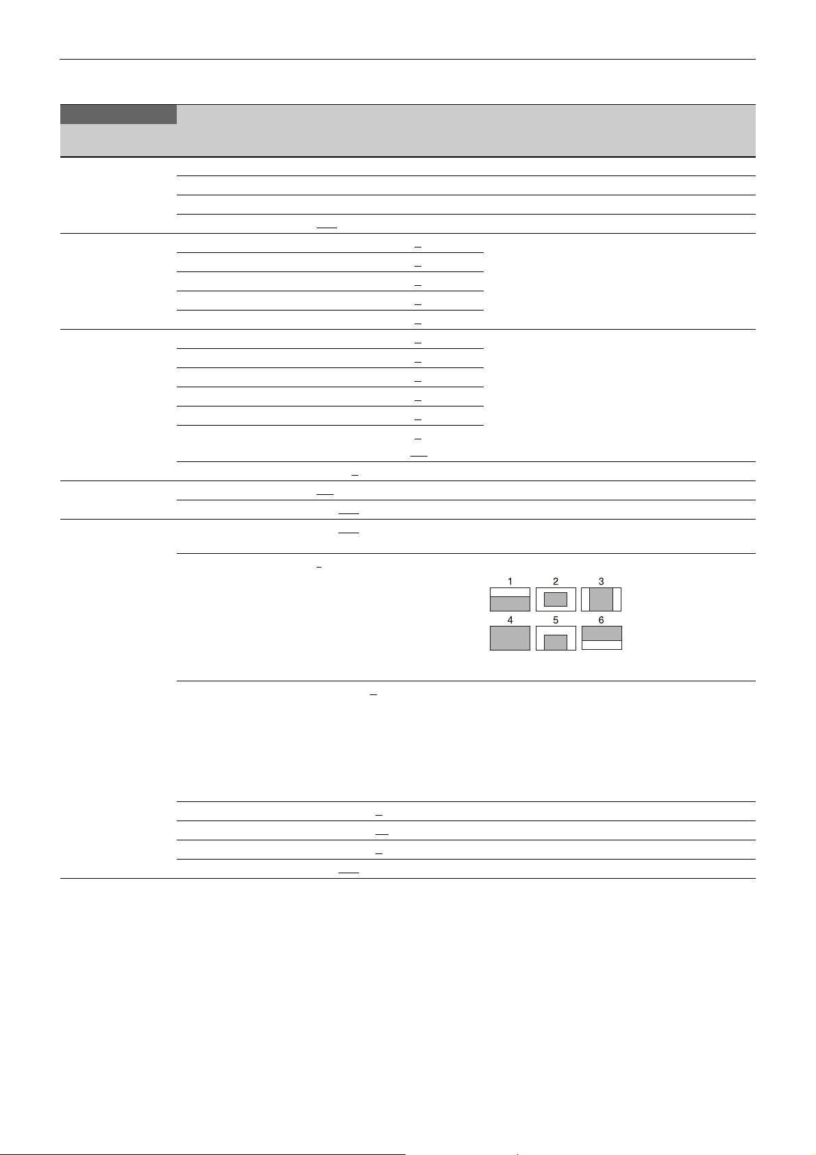
MAINTENANCE Menu
MAINTENANCE
Page name
Page No.
<AUTO SETUP>
M01
<WHITE SHADING>
M02
<BLACK SHADING>
M03
<OHB MATRIX>
M04
<AUTO IRIS>
M05
Item Settings Description
AUTO BLACK Execute using ENTER.
AUTO WHITE Execute using ENTER.
AUTO LEVEL Execute using ENTER.
TEST OFF
V SAW R/G/B: –99 to +99, 0
V PARA R/G/B: –99 to +99, 0
H SAW R/G/B: –99 to +99, 0
H PARA R/G/B: –99 to +99, 0
WHITE R/G/B: –99 to +99, 0
V SAW R/G/B: –99 to +99, 0 R, G, and B values can be independently set.
V PARA R/G/B: –99 to +99, 0
H SAW R/G/B: –99 to +99, 0
H PARA R/G/B: –99 to +99, 0
BLK SET R/G/B: –99 to +99, 0
BLACK R/G/B: –99 to +99, 0
MASTER GAIN –6, –3, 0, 3, 6, 9, 12 dB
OHB MATRIX ON
MATRIX ON, OFF
AUTO IRIS ON, OFF, (ON), (OFF) Settings in ( ): When a remote control unit/panel or a
WINDOW 1
, SAW, 10STEP
R, G, and B values can be independently set.
M (master) value can also be set for BLACK.
M: –99.9 to +99.9, 0.0
, OFF
CCU is not connected (cannot be changed)
, 2, 3, 4, 5, 6 Selects the auto iris windows:
OVERRIDE –99 to 99, 0
IRIS LEVEL –99 to +99, 0
APL RATIO –99 to +99, 65
IRIS GAIN –99 to +99, 0
IRIS CLOSE ON, OFF
, --- Sets the override to temporarily change the
The shaded parts indicate the area where light
detection occurs.
reference value for brightness of the automatic iris
level in the range of ±2 steps:
–99: Two steps to fully closed iris.
99: Two steps to fully opened iris.
---: OFF
The setting returns to “---” when the power is
turned off.
±4 steps
60
Page 61

MAINTENANCE
Page name
Page No.
<LENS1>
M06
<LENS2>
M07
Item Settings Description
F NO. DISP CONTROL
AF DISPLAY ON, OFF
ALAC AUTO, OFF With AUTO selected, the status is displayed at the
F DROP COMP OFF
MAX GAIN 0.0
DROP POINT 0 to 99, 50
ROUNDNESS 0.0
STORE LENS FILE Execute using ENTER. Saves settings to a lens file.
ARIA AUTO, OFF
GAIN LIMIT 0 to 12 dB, OFF
REMOTE CONTROL OFF, ON, (OFF)
CONTROL MODE ZOOM&FOCUS
FOLLOW FOCUS
, RETURN Selects the iris indication on the panel when AUTO
, ON, (OFF) Turns F drop compensation on/off.
to 24.0 dB Maximum compensation value
to 12.0 dB Roundness of the compensation curve.
With AUTO selected, the status is displayed at the
, FOCUS,
IRIS is off:
CONTROL: Displays the value from the camera.
RETURN: Displays the value returned from the lens.
(When AUTO IRIS is on, the value returned from the
lens is always displayed.)
right.
(ACTIVE): Compensation is in progress.
(WAIT): Waiting for completion of lens initialization.
(STOP): Compensation is turned off for a non-
applicable lens.
During compensation, the compensation gain is
displayed on the right.
(OFF): For when a serial lens is not attached.
Compensation start point
right.
(ACTIVE): Compensation is in progress.
(WAIT): Waiting for completion of lens initialization.
(STOP): Compensation is turned off for a non-
applicable lens.
Lens remote control from MSU/RCP on/off setting.
Same function as the Active button on the Zoom/
Focus Control screen of the MSU/RCP.
(OFF): When lens is not supported
ZOOM&FOCUS: Control ZOOM and FOCUS from an
MSU/RCP (control by lens demand is not
supported)
FOCUS: Control FOCUS from an MSU/RCP. ZOOM is
controlled by lens demand.
FOLLOW FOCUS: FOCUS is controlled by lens
demand, but can be adjusted (offset fine
adjustment) from an MSU/RCP. ZOOM is
controlled by lens demand.
<MIC GAIN>
M08
FOLLOW FOCUS
OFFSET ADJUST SENS 1, 2, 3
OFFSET CANCEL GAIN 1, 2, 3
MIC1 20, 30, 40, 50, 60
MIC2 20, 30, 40, 50, 60
, 4, 5 Sets the sensitivity of superimposing the offset of
, 4, 5 Sets the sensitivity of canceling the offset on the
Note
Settings other than FOLLOW FOCUS cannot be
modified when the offset is not 0 and REMOTE
CONTROL is OFF. To change settings, set REMOTE
CONTROL to ON.
the MSU.
demand side.
dB Can be modified only in standalone operation.
dB
61
Page 62
MAINTENANCE
Page name
Page No.
<CAMERA NUMBER>
M09
<CALL/TALLY>
M10
<OUTPUT FORMAT>
M11 (U12)
Item Settings Description
CAMERA NUMBER ---
CCU LINK OFF
, 1 to 96 Sets the camera number.
, ON Turns the link with the CCU No. on/off.
When on, you can set the camera number from the
CCU.
OUTSIDE DISPLAY
CAMERA NUMBER OFF
, ON Turns the camera number display on the side panel
on/off.
X –100 to 100, 0
Sets the text position of the camera number (0:
center position)
Y –100 to 100, 0
Sets the text position of the camera number (0:
center position)
SIZE 0 to 150, 100
Sets the text size of the camera number.
BACK GROUND BLACK, WHITE, LOGO Sets the background color.
LOGO: Set imported logo as the background.
READ LOGO Import logo data (BMP file) to use for the
background color.
To import logo data into the camera, prepare
monochrome 200×200 pixel data. Change the file
name of the data to “logo.bmp”, copy the file to a
USB drive, connect the drive to the unit, and then
select READ LOGO in the menu.
DELETE LOGO Deletes the configured logo data.
CCU CALL OFF, ON
CAM CALL OFF
, ON
Selects whether TALLY lights for CALL signal.
HDLA UP TALLY
TALLY BRIGHTNESS 0 to 100, 50
NUMBER
0 to 100, 50
BRIGHTNESS
NUMBER DISPLAY AUTO, OFF, ON
OUTSIDE LED Sets the display mode of the LED on the side panel.
MODE OFF, TALLY
, LIGHT TALLY: Function as a tally.
LIGHT: Function as a light.
BRIGHTNESS 0 to 100, 50
Sets the brightness of the LED.
TALLY GUARD Selects whether to prevent changes while TALLY is
EXTENDER OFF
FILTER DISC OFF
, ON
, ON
lit.
CURRENT Display only Displays the current format.
RESOLUTION 3840×2160, 1920×1080
FREQUENCY 59.94P, 50P
Not displayed when a CCU is connected.
System format settings (The selectable system
formats vary depending on camera operating
software options.)
OETF SDR
, S-Log3, HLG_Live,
HLG_BT.2100
COLOR BT.709
, BT.2020 Not displayed when a CCU is connected.
Not displayed when a CCU is connected.
Camera OETF setting
Camera color space setting
BIT DEPTH 10bit
, 12bit Not displayed when a CCU is connected.
Can be selected for RGB 444 only.
62
Page 63
MAINTENANCE
Page name
Page No.
<TEST OUT>
M12 (U13)
<SDI OUT>
M13 (U14)
<TRUNK>
M14
<GENLOCK>
M15
<DATE>
M16
<BATTERY ALARM>
M17
<SIMPLE PROTOCOL>
M18
Item Settings Description
OUTPUT Display only Displays the current format.
VBS-OUT Displayed when OUTPUT is set to VBS.
CHARACTER ON, OFF
GAIN –99 to +99, 0
CHROMA –99 to +99, 0
SETUP OFF, ON
DOWN CONVERTER Displayed when OUTPUT is set to VBS.
SELECT MAIN
ASPECT SQ
SYNC-OUT Displayed when OUTPUT is set to SD-SYNC or
V-PHASE –999 to +999, 0
H-PHASE –999 to +999, 0
SDI-1
SDI-2
SDI-MONI OUT MAIN, VF
CHARACTER ON, OFF
EMB AUDIO OFF
DOWN CONVERTER Displayed when SDI-MONI OUT is set to SD-SDI.
SELECT MAIN
ASPECT SQ
TRUNK ON
INTERFACE 232c
AUX REMOTE Display only
NETWORK TRUNK Display only
LINK
REFERENCE Synchronization status Display only
GENLOCK ENABLE
STATUS
FORMAT
PHASE
V –1024 to 1023, 0
H –1700 to 1700, 0
DATE/TIME 2000 to 2035/01 to 12/00 to 31
DATE FORMAT 1 Y/Mn/D, 2 Mn/D, 3 D/M/Y
BEFORE END 11.5
END 11.0
TRANSPORT CONVERTER
MODE
PORT REMOTE(RS-422A)
BAUDRATE 9.6kbps to 843.75kbps,
, RET, VF
, EC Displayed when OUTPUT is set to VBS (NTSC).
HD-SYNC.
See “SDI output format with
Sets the SDI-1 and SDI-2 output formats.
master frequency of 1/1.001”
(page 64).
, RET, SD-SDI, OFF
Displayed when SDI-MONI OUT is not set to VF.
, MIC, PGM
, RET, VF
, EC
, OFF
, 422A
, DISABLE Not displayed when a CCU is connected.
00 to 23: 00 to 59
4 D/M, 5 M/D/Y
to 17.0 V
to 11.5 V
DISABLE
CRANE(RS-422A),
CRANE(RS-232C), WIRELESS SIDE
PANEL(RS-422A), WIRELESS SIDE
PANEL(RS-232C)
115.2kbps
, 6 M/D
, ENABLE Enables transport conversion mode to enable
,
Y: Year
Mn: Month (numeric)
M: Month (English abbreviation)
D: Day
camera control using transmission lines/networks
with high latency, such as wireless transmission.
Sets the port to enable for transport conversion
mode.
WIRELESS SIDE PANEL(RS-422A) or WIRELESS SIDE
PANEL(RS-232C) can be selected only when an
HKC-WL50 Wireless Transmission Adaptor is
installed.
Communication speed
63
Page 64
MAINTENANCE
Page name
Item Settings Description
Page No.
<OTHERS>
M19
FAN MODE OFF, AUTO1
CAM BARS ON, OFF
, (OFF) (OFF): Displayed only for 4K/HDR format.
, AUTO2, MIN, MAX AUTO1: Normal rotation
AUTO2: Slow rotation
WHITE SETUP MODE AWB, A.LVL
STANDALONE PAINT
SWITCH
OFF, ON When set to ON, disables operation of the unit’s
switches, such as the WHITE BAL switch, even when
a CCU or control panel is not connected.
, 2, 3, 4, 1(V0.3), 1(V0.6), (4) (4): Displayed only for 4K/HDR format.
<OPTION KEY>
M20
HD DOWNCONV FILTER 1
READ (USB t CAM) Execute using ENTER. Reads the install key from a USB drive.
EFFECTIVE FUNCTION Displayed only when option function is installed.
SDI output format with master frequency of 1/1.001
The following table shows the SDI output formats when the master frequency is 1/1.001.
The SDI output format will vary depending on the combination of camera model, transmission adaptor, and camera
operating software.
1. Using HDC5500 or HDC3500 with HKC-CN50 and HKC-FB50 installed
<Standard format>
SYSTEM FORMAT HDR/
SDR
RESOLUTION
FREQUENCY OETF Settings Output formats Settings Output formats
1920×1080 59.94P S-Log3
HLG
SDR OFF
OUTPUT FORMAT
SDI-1 SDI-2
OFF
HD/3G-A/HDR
HD/3G-A/SDR
HD/3G-B/HDR
HD/3G-B/SDR
HD/1.5G/SDR
UHD PROMPTER
–
1920×1080/59.94P
1920×1080/59.94P
1920×1080/59.94P
1920×1080/59.94P
1920×1080/59.94i
–
OFF
HD/3G-A/HDR
HD/3G-A/SDR
HD/3G-B/HDR
HD/3G-B/SDR
HD/1.5G/SDR
UHD TRUNK(12G) IN
UHD TRUNK(6G) IN
UHD TRUNK(3G) IN
HD/UHD TRUNK(1.5G) IN
HD RETURN IN
HD/3G-A/SDR
HD/3G-B/SDR
HD/1.5G/SDR
UHD PROMPTER
–
1920×1080/59.94P
1920×1080/59.94P
1920×1080/59.94i
–
OFF
HD/3G-A/SDR
HD/3G-B/SDR
HD/1.5G/SDR
UHD TRUNK(12G) IN
UHD TRUNK(6G) IN
UHD TRUNK(3G) IN
HD/UHD TRUNK(1.5G) IN
HD RETURN IN
–
1920×1080/59.94P
1920×1080/59.94P
1920×1080/59.94P
1920×1080/59.94P
1920×1080/59.94i
*1 *2
–
*1 *2
–
*1 *2
–
*2
–
*3
–
–
1920×1080/59.94P
1920×1080/59.94P
1920×1080/59.94i
*1 *2
–
*1 *2
–
*1 *2
–
*2
–
*3
–
*1
Can be selected only when NETWORK TRUNK > DATA RATE (setting on the CCU) is set to 100Mbps.
*2
Can be selected only when a CCU is connected.
*3
Can be selected only in standalone operation.
64
Page 65
<When HZC-PSF50/PSF50M/PSF50W is installed>
SYSTEM FORMAT HDR/
SDR
RESOLUTION
FREQUENCY OETF Settings Output formats Settings Output formats
1920×1080 29.97PsF S-Log3
HLG
SDR OFF
23.98PsF S-Log3
HLG
SDR OFF
29.97PsF(444)
(HZC-UG50 is
SDR
(fixed)
required)
23.98PsF(444)
(HZC-UG50 is
SDR
(fixed)
required)
OUTPUT FORMAT
SDI-1 SDI-2
OFF
HD/1.5G/HDR
HD/1.5G/SDR
UHD PROMPTER
–
1920×1080/29.97PsF
1920×1080/29.97PsF
–
OFF
HD/1.5G/HDR
HD/1.5G/SDR
UHD TRUNK(12G) IN
UHD TRUNK(6G) IN
UHD TRUNK(3G) IN
HD/UHD TRUNK(1.5G) IN
HD RETURN IN
HD/1.5G/SDR
UHD PROMPTER
–
1920×1080/29.97PsF
–
OFF
HD/1.5G/SDR
UHD TRUNK(12G) IN
UHD TRUNK(6G) IN
UHD TRUNK(3G) IN
HD/UHD TRUNK(1.5G) IN
HD RETURN IN
OFF
HD/1.5G/HDR
HD/1.5G/SDR
UHD PROMPTER
–
1920×1080/23.98PsF
1920×1080/23.98PsF
–
OFF
HD/1.5G/HDR
HD/1.5G/SDR
UHD TRUNK(12G) IN
UHD TRUNK(6G) IN
UHD TRUNK(3G) IN
HD/UHD TRUNK(1.5G) IN
HD RETURN IN
HD/1.5G/SDR
UHD PROMPTER
–
1920×1080/23.98PsF
–
OFF
HD/1.5G/SDR
UHD TRUNK(12G) IN
UHD TRUNK(6G) IN
UHD TRUNK(3G) IN
HD/UHD TRUNK(1.5G) IN
HD RETURN IN
OFF
HD/3G-B/SDR
UHD PROMPTER
–
1920×1080/29.97PsF(444)
–
OFF
HD/3G-B/SDR
UHD TRUNK(12G) IN
UHD TRUNK(6G) IN
UHD TRUNK(3G) IN
HD/UHD TRUNK(1.5G) IN
HD RETURN IN
OFF
HD/3G-B/SDR
UHD PROMPTER
–
1920×1080/23.98PsF(444)
–
OFF
HD/3G-B/SDR
UHD TRUNK(12G) IN
UHD TRUNK(6G) IN
UHD TRUNK(3G) IN
HD/UHD TRUNK(1.5G) IN
HD RETURN IN
–
1920×1080/29.97PsF
1920×1080/29.97PsF
*1 *2
–
*1 *2
–
*1 *2
–
*2
–
*3
–
–
1920×1080/29.97PsF
*1 *2
–
*1 *2
–
*1 *2
–
*2
–
*3
–
–
1920×1080/23.98PsF
1920×1080/23.98PsF
*1 *2
–
*1 *2
–
*1 *2
–
*2
–
*3
–
–
1920×1080/23.98PsF
*1 *2
–
*1 *2
–
*1 *2
–
*2
–
*3
–
–
1920×1080/29.97PsF(444)
*1 *2
–
*1 *2
–
*1 *2
–
*2
–
*3
–
–
1920×1080/23.98PsF(444)
*1 *2
–
*1 *2
–
*1 *2
–
*2
–
*3
–
*1
Can be selected only when NETWORK TRUNK > DATA RATE (setting on the CCU) is set to 100Mbps.
*2
Can be selected only when a CCU is connected.
*3
Can be selected only in standalone operation.
65
Page 66
<When HZC-HFR50/HFR50M/HFR50W/HFR50P is installed>
SYSTEM FORMAT HDR/
SDR
RESOLUTION
FREQUENCY OETF Settings Output formats Settings Output formats
1920×1080 59.94P(2×) S-Log3
HLG
SDR OFF
59.94P(3×) S-Log3
HLG
SDR OFF
OUTPUT FORMAT
SDI-1 SDI-2
OFF
HD/12G/HDR/HFR
HD/3G-A/HDR/HFR
HD/3G-B/HDR/HFR
HD/3G-A/SDR
HD/3G-B/SDR
HD/1.5G/SDR
UHD PROMPTER
–
1920×1080/59.94P/Link A-B
1920×1080/59.94P/Link A
1920×1080/59.94P/Link A
1920×1080/59.94P
1920×1080/59.94P
1920×1080/59.94i
–
OFF
HD/12G/HDR/HFR
HD/3G-A/HDR/HFR
HD/3G-B/HDR/HFR
HD/3G-A/SDR
HD/3G-B/SDR
HD/1.5G/SDR
UHD TRUNK(12G) IN
UHD TRUNK(6G) IN
UHD TRUNK(3G) IN
HD/UHD TRUNK(1.5G) IN
HD RETURN IN
HD/12G/SDR/HFR
HD/3G-A/SDR/HFR
HD/3G-B/SDR/HFR
HD/3G-B/SDR/HFR(i)
HD/3G-A/SDR
HD/3G-B/SDR
HD/1.5G/SDR
UHD PROMPTER
–
1920×1080/59.94P/Link A-B
1920×1080/59.94P/Link A
1920×1080/59.94P/Link A
1920×1080/59.94i/Link A-B
1920×1080/59.94P
1920×1080/59.94P
1920×1080/59.94i
–
OFF
HD/12G/SDR/HFR
HD/3G-A/SDR/HFR
HD/3G-B/SDR/HFR
HD/3G-B/SDR/HFR(i)
HD/3G-A/SDR
HD/3G-B/SDR
HD/1.5G/SDR
UHD TRUNK(12G) IN
UHD TRUNK(6G) IN
UHD TRUNK(3G) IN
HD/UHD TRUNK(1.5G) IN
HD RETURN IN
OFF
HD/12G/HDR/HFR
HD/3G-A/SDR
HD/3G-B/SDR
HD/1.5G/SDR
UHD PROMPTER
–
1920×1080/59.94P/Link A-C
1920×1080/59.94P
1920×1080/59.94P
1920×1080/59.94i
–
OFF
HD/12G/HDR/HFR
HD/3G-A/SDR
HD/3G-B/SDR
HD/1.5G/SDR
UHD TRUNK(12G) IN
UHD TRUNK(6G) IN
UHD TRUNK(3G) IN
HD/UHD TRUNK(1.5G) IN
HD RETURN IN
HD/12G/SDR/HFR
HD/3G-A/SDR
HD/3G-B/SDR
HD/1.5G/SDR
UHD PROMPTER
–
1920×1080/59.94P/Link A-C
1920×1080/59.94P
1920×1080/59.94P
1920×1080/59.94i
–
OFF
HD/12G/SDR/HFR
HD/3G-A/SDR
HD/3G-B/SDR
HD/1.5G/SDR
UHD TRUNK(12G) IN
UHD TRUNK(6G) IN
UHD TRUNK(3G) IN
HD/UHD TRUNK(1.5G) IN
HD RETURN IN
–
1920×1080/59.94P/Link A-B
1920×1080/59.94P/Link B
1920×1080/59.94P/Link B
1920×1080/59.94P
1920×1080/59.94P
1920×1080/59.94i
*1 *2
–
*1 *2
–
*1 *2
–
*2
–
*3
–
–
1920×1080/59.94P/Link A-B
1920×1080/59.94P/Link B
1920×1080/59.94P/Link B
1920×1080/59.94i/Link A-B
1920×1080/59.94P
1920×1080/59.94P
1920×1080/59.94i
*1 *2
–
*1 *2
–
*1 *2
–
*2
–
*3
–
–
1920×1080/59.94P/Link A-C
1920×1080/59.94P
1920×1080/59.94P
1920×1080/59.94i
*1 *2
–
*1 *2
–
*1 *2
–
*2
–
*3
–
–
1920×1080/59.94P/Link A-C
1920×1080/59.94P
1920×1080/59.94P
1920×1080/59.94i
*1 *2
–
*1 *2
–
*1 *2
–
*2
–
*3
–
66
Page 67
SYSTEM FORMAT HDR/
SDR
RESOLUTION
FREQUENCY OETF Settings Output formats Settings Output formats
1920×1080 59.94P(4×) S-Log3
HLG
SDR OFF
59.94P(6×) All OFF
59.94P(8×) All OFF
3840×2160 59.94P(2×)
(HZC-UHD50 is
S-Log3
HLG
required)
SDR OFF
OUTPUT FORMAT
SDI-1 SDI-2
OFF
HD/12G/HDR/HFR
HD/3G-A/SDR
HD/3G-B/SDR
HD/1.5G/SDR
UHD PROMPTER
–
1920×1080/59.94P/Link A-D
1920×1080/59.94P
1920×1080/59.94P
1920×1080/59.94i
–
OFF
HD/12G/HDR/HFR
HD/3G-A/SDR
HD/3G-B/SDR
HD/1.5G/SDR
UHD TRUNK(12G) IN
UHD TRUNK(6G) IN
UHD TRUNK(3G) IN
HD/UHD TRUNK(1.5G) IN
HD RETURN IN
HD/12G/SDR/HFR
HD/3G-A/SDR
HD/3G-B/SDR
HD/1.5G/SDR
UHD PROMPTER
–
1920×1080/59.94P/Link A-D
1920×1080/59.94P
1920×1080/59.94P
1920×1080/59.94i
–
OFF
HD/12G/SDR/HFR
HD/3G-A/SDR
HD/3G-B/SDR
HD/1.5G/SDR
UHD TRUNK(12G) IN
UHD TRUNK(6G) IN
UHD TRUNK(3G) IN
HD/UHD TRUNK(1.5G) IN
HD RETURN IN
– OFF –
– OFF –
OFF
4K/12G/HDR/HFR
4K/12G/HDR
HD/3G-A/SDR
HD/3G-B/SDR
HD/1.5G/SDR
UHD PROMPTER
–
3840×2160/59.94P/Link A
3840×2160/59.94P
1920×1080/59.94P
1920×1080/59.94P
1920×1080/59.94i
–
OFF
4K/12G/HDR/HFR
4K/12G/HDR
HD/3G-A/SDR
HD/3G-B/SDR
HD/1.5G/SDR
HD/UHD TRUNK(1.5G) IN
HD RETURN IN
OFF
4K/12G/SDR/HFR
4K/12G/SDR
HD/3G-A/SDR
HD/3G-B/SDR
HD/1.5G/SDR
HD/UHD TRUNK(1.5G) IN
4K/12G/SDR/HFR
4K/12G/SDR
HD/3G-A/SDR
HD/3G-B/SDR
HD/1.5G/SDR
UHD PROMPTER
–
3840×2160/59.94P/Link A
3840×2160/59.94P
1920×1080/59.94P
1920×1080/59.94P
1920×1080/59.94i
–
HD RETURN IN
–
1920×1080/59.94P/Link A-D
1920×1080/59.94P
1920×1080/59.94P
1920×1080/59.94i
*1 *2
–
*1 *2
–
*1 *2
–
*2
–
*3
–
–
1920×1080/59.94P/Link A-D
1920×1080/59.94P
1920×1080/59.94P
1920×1080/59.94i
*1 *2
–
*1 *2
–
*1 *2
–
*2
–
*3
–
–
3840×2160/59.94P/Link B
3840×2160/59.94P
1920×1080/59.94P
1920×1080/59.94P
1920×1080/59.94i
*2
–
*3
–
–
3840×2160/59.94P/Link B
3840×2160/59.94P
1920×1080/59.94P
1920×1080/59.94P
1920×1080/59.94i
*2
–
*3
–
*1
Can be selected only when NETWORK TRUNK > DATA RATE (setting on the CCU) is set to 100Mbps.
*2
Can be selected only when a CCU is connected.
*3
Can be selected only in standalone operation.
67
Page 68
<When HZC-DFR50/DFR50M/DFR50W is installed>
SYSTEM FORMAT HDR/
SDR
RESOLUTION
FREQUENCY OETF Settings Output formats Settings Output formats
1920×1080 59.94P(2×) S-Log3
HLG
SDR OFF
OUTPUT FORMAT
SDI-1 SDI-2
OFF
HD/12G/HDR/HFR
HD/3G-A/HDR/HFR
HD/3G-B/HDR/HFR
HD/3G-A/SDR
HD/3G-B/SDR
HD/1.5G/SDR
UHD PROMPTER
–
1920×1080/59.94P/Link A-B
1920×1080/59.94P/Link A
1920×1080/59.94P/Link A
1920×1080/59.94P
1920×1080/59.94P
1920×1080/59.94i
–
OFF
HD/12G/HDR/HFR
HD/3G-A/HDR/HFR
HD/3G-B/HDR/HFR
HD/3G-A/SDR
HD/3G-B/SDR
HD/1.5G/SDR
UHD TRUNK(12G) IN
UHD TRUNK(6G) IN
UHD TRUNK(3G) IN
HD/UHD TRUNK(1.5G) IN
HD RETURN IN
HD/12G/SDR/HFR
HD/3G-A/SDR/HFR
HD/3G-B/SDR/HFR
HD/3G-B/SDR/HFR(i)
HD/3G-A/SDR
HD/3G-B/SDR
HD/1.5G/SDR
UHD PROMPTER
–
1920×1080/59.94P/Link A-B
1920×1080/59.94P/Link A
1920×1080/59.94P/Link A
1920×1080/59.94i/Link A-B
1920×1080/59.94P
1920×1080/59.94P
1920×1080/59.94i
–
OFF
HD/12G/SDR/HFR
HD/3G-A/SDR/HFR
HD/3G-B/SDR/HFR
HD/3G-B/SDR/HFR(i)
HD/3G-A/SDR
HD/3G-B/SDR
HD/1.5G/SDR
UHD TRUNK(12G) IN
UHD TRUNK(6G) IN
UHD TRUNK(3G) IN
HD/UHD TRUNK(1.5G) IN
HD RETURN IN
–
1920×1080/59.94P/Link A-B
1920×1080/59.94P/Link B
1920×1080/59.94P/Link B
1920×1080/59.94P
1920×1080/59.94P
1920×1080/59.94i
*1 *2
–
*1 *2
–
*1 *2
–
*2
–
*3
–
–
1920×1080/59.94P/Link A-B
1920×1080/59.94P/Link B
1920×1080/59.94P/Link B
1920×1080/59.94i/Link A-B
1920×1080/59.94P
1920×1080/59.94P
1920×1080/59.94i
*1 *2
–
*1 *2
–
*1 *2
–
*2
–
*3
–
*1
Can be selected only when NETWORK TRUNK > DATA RATE (setting on the CCU) is set to 100Mbps.
*2
Can be selected only when a CCU is connected.
*3
Can be selected only in standalone operation.
68
Page 69
<When HZC-UG50/UG50M/UG50W is installed>
SYSTEM FORMAT HDR/
SDR
RESOLUTION
FREQUENCY OETF Settings Output formats Settings Output formats
1920×1080 59.94i(444) SDR
(fixed)
29.97PsF(444)
(HZC-PSF50 is
SDR
(fixed)
required)
23.98PsF(444)
(HZC-PSF50 is
SDR
(fixed)
required)
OUTPUT FORMAT
SDI-1 SDI-2
OFF
HD/3G-B/SDR
UHD PROMPTER
–
1920×1080/59.94i(444)
–
OFF
HD/3G-B/SDR
UHD TRUNK(12G) IN
UHD TRUNK(6G) IN
UHD TRUNK(3G) IN
HD/UHD TRUNK(1.5G) IN
HD RETURN IN
OFF
HD/3G-B/SDR
UHD PROMPTER
–
1920×1080/29.97PsF(444)
–
OFF
HD/3G-B/SDR
UHD TRUNK(12G) IN
UHD TRUNK(6G) IN
UHD TRUNK(3G) IN
HD/UHD TRUNK(1.5G) IN
HD RETURN IN
OFF
HD/3G-B/SDR
UHD PROMPTER
–
1920×1080/23.98PsF(444)
–
OFF
HD/3G-B/SDR
UHD TRUNK(12G) IN
UHD TRUNK(6G) IN
UHD TRUNK(3G) IN
HD/UHD TRUNK(1.5G) IN
HD RETURN IN
–
1920×1080/59.94i(444)
*1 *2
–
*1 *2
–
*1 *2
–
*2
–
*3
–
–
1920×1080/29.97PsF(444)
*1 *2
–
*1 *2
–
*1 *2
–
*2
–
*3
–
–
1920×1080/23.98PsF(444)
*1 *2
–
*1 *2
–
*1 *2
–
*2
–
*3
–
*1
Can be selected only when NETWORK TRUNK > DATA RATE (setting on the CCU) is set to 100Mbps.
*2
Can be selected only when a CCU is connected.
*3
Can be selected only in standalone operation.
69
Page 70
<When HZC-UHD50/UHD50M/UHD50W/UHD50P is installed>
SYSTEM FORMAT HDR/
SDR
RESOLUTION
FREQUENCY OETF Settings Output formats Settings Output formats
3840×2160 59.94P S-Log3
HLG
SDR OFF
29.97P S-Log3
HLG
SDR OFF
23.98P S-Log3
HLG
SDR OFF
OUTPUT FORMAT
SDI-1 SDI-2
OFF
4K/12G/HDR
HD/3G-A/SDR
HD/3G-B/SDR
HD/1.5G/SDR
UHD PROMPTER
–
3840×2160/59.94P
1920×1080/59.94P
1920×1080/59.94P
1920×1080/59.94i
–
OFF
4K/12G/HDR
HD/3G-A/SDR
HD/3G-B/SDR
HD/1.5G/SDR
UHD TRUNK(12G) IN
UHD TRUNK(6G) IN
UHD TRUNK(3G) IN
HD/UHD TRUNK(1.5G) IN
HD RETURN IN
4K/12G/SDR
HD/3G-A/SDR
HD/3G-B/SDR
HD/1.5G/SDR
UHD PROMPTER
–
3840×2160/59.94P
1920×1080/59.94P
1920×1080/59.94P
1920×1080/59.94i
–
OFF
4K/12G/SDR
HD/3G-A/SDR
HD/3G-B/SDR
HD/1.5G/SDR
UHD TRUNK(12G) IN
UHD TRUNK(6G) IN
UHD TRUNK(3G) IN
HD/UHD TRUNK(1.5G) IN
HD RETURN IN
OFF
4K/6G/HDR
HD/1.5G/SDR
UHD PROMPTER
–
3840×2160/29.97P
1920×1080/29.97PsF
–
OFF
4K/6G/HDR
HD/1.5G/SDR
UHD TRUNK(12G) IN
UHD TRUNK(6G) IN
UHD TRUNK(3G) IN
HD/UHD TRUNK(1.5G) IN
HD RETURN IN
4K/6G/SDR
HD/1.5G/SDR
UHD PROMPTER
–
3840×2160/29.97P
1920×1080/29.97PsF
–
OFF
4K/6G/SDR
HD/1.5G/SDR
UHD TRUNK(12G) IN
UHD TRUNK(6G) IN
UHD TRUNK(3G) IN
HD/UHD TRUNK(1.5G) IN
HD RETURN IN
OFF
4K/6G/SDR
HD/1.5G/SDR
UHD PROMPTER
–
3840×2160/23.98P
1920×1080/23.98PsF
–
OFF
4K/6G/SDR
HD/1.5G/SDR
UHD TRUNK(12G) IN
UHD TRUNK(6G) IN
UHD TRUNK(3G) IN
HD/UHD TRUNK(1.5G) IN
HD RETURN IN
4K/6G/SDR
HD/1.5G/SDR
UHD PROMPTER
–
3840×2160/23.98P
1920×1080/23.98PsF
–
OFF
4K/6G/SDR
HD/1.5G/SDR
UHD TRUNK(12G) IN
UHD TRUNK(6G) IN
UHD TRUNK(3G) IN
HD/UHD TRUNK(1.5G) IN
HD RETURN IN
–
3840×2160/59.94P
1920×1080/59.94P
1920×1080/59.94P
1920×1080/59.94i
*1 *2
–
*1 *2
–
*1 *2
–
*2
–
*3
–
–
3840×2160/59.94P
1920×1080/59.94P
1920×1080/59.94P
1920×1080/59.94i
*1 *2
–
*1 *2
–
*1 *2
–
*2
–
*3
–
–
3840×2160/29.97P
1920×1080/29.97PsF
*1 *2
–
*1 *2
–
*1 *2
–
*2
–
*3
–
–
3840×2160/29.97P
1920×1080/29.97PsF
*1 *2
–
*1 *2
–
*1 *2
–
*2
–
*3
–
–
3840×2160/23.98P
1920×1080/23.98PsF
*1 *2
–
*1 *2
–
*1 *2
–
*2
–
*3
–
–
3840×2160/23.98P
1920×1080/23.98PsF
*1 *2
–
*1 *2
–
*1 *2
–
*2
–
*3
–
70
Page 71
SYSTEM FORMAT HDR/
SDR
RESOLUTION
3840×2160 59.94P(2×)
FREQUENCY OETF Settings Output formats Settings Output formats
S-Log3
(HZC-HFR50 is
HLG
required)
OUTPUT FORMAT
SDI-1 SDI-2
OFF
4K/12G/HDR/HFR
4K/12G/HDR
HD/3G-A/SDR
HD/3G-B/SDR
HD/1.5G/SDR
UHD PROMPTER
–
3840×2160/59.94P/Link A
3840×2160/59.94P
1920×1080/59.94P
1920×1080/59.94P
1920×1080/59.94i
–
OFF
4K/12G/HDR/HFR
4K/12G/HDR
HD/3G-A/SDR
HD/3G-B/SDR
HD/1.5G/SDR
HD/UHD TRUNK(1.5G) IN
HD RETURN IN
SDR OFF
4K/12G/SDR/HFR
4K/12G/SDR
HD/3G-A/SDR
HD/3G-B/SDR
HD/1.5G/SDR
UHD PROMPTER
–
3840×2160/59.94P/Link A
3840×2160/59.94P
1920×1080/59.94P
1920×1080/59.94P
1920×1080/59.94i
–
OFF
4K/12G/SDR/HFR
4K/12G/SDR
HD/3G-A/SDR
HD/3G-B/SDR
HD/1.5G/SDR
HD/UHD TRUNK(1.5G) IN
HD RETURN IN
*1
Can be selected only when NETWORK TRUNK > DATA RATE (setting on the CCU) is set to 100Mbps.
*2
Can be selected only when a CCU is connected.
*3
Can be selected only in standalone operation.
–
3840×2160/59.94P/Link B
3840×2160/59.94P
1920×1080/59.94P
1920×1080/59.94P
1920×1080/59.94i
*2
–
*3
–
–
3840×2160/59.94P/Link B
3840×2160/59.94P
1920×1080/59.94P
1920×1080/59.94P
1920×1080/59.94i
*2
–
*3
–
2. Using HDC3500 (or HDC3500 serial number 20000 series, with HKC-CN50 and HKC-FB30 installed)
<Standard format>
SYSTEM FORMAT HDR/
SDR
RESOLUTION
FREQUENCY OETF Settings Output formats Settings Output formats
1920×1080 59.94i SDR
(fixed)
1280×720 59.94P SDR
(fixed)
*1
Can be selected only when a CCU is connected.
*2
Can be selected only in standalone operation.
OUTPUT FORMAT
SDI-1 SDI-2
OFF
HD/1.5G/SDR
HD PROMPTER
–
1920×1080/59.94i
–
OFF
HD/1.5G/SDR
HD TRUNK IN
RET IN
OFF
HD/1.5G/SDR
HD PROMPTER
–
1280×720/59.94P
–
OFF
HD/1.5G/SDR
HD TRUNK IN
RET IN
–
1920×1080/59.94i
*1
*2
–
–
–
1280×720/59.94P
*1
*2
–
–
71
Page 72
<When HZC-PSF50/PSF50M/PSF50W is installed>
SYSTEM FORMAT HDR/
SDR
RESOLUTION
FREQUENCY OETF Settings Output formats Settings Output formats
1920×1080 29.97PsF SDR
(fixed)
23.98PsF SDR
(fixed)
29.97PsF(444)
(HZC-UG50 is
SDR
(fixed)
required)
23.98PsF(444)
(HZC-UG50 is
SDR
(fixed)
required)
*1
Can be selected only when a CCU is connected.
*2
Can be selected only in standalone operation.
OUTPUT FORMAT
SDI-1 SDI-2
OFF
HD/1.5G/SDR
HD PROMPTER
–
1920×1080/29.97PsF
–
OFF
HD/1.5G/SDR
HD TRUNK IN
RET IN
OFF
HD/1.5G/SDR
HD PROMPTER
–
1920×1080/23.98PsF
–
OFF
HD/1.5G/SDR
HD TRUNK IN
RET IN
OFF
HD/3G-B/SDR
HD PROMPTER
–
1920×1080/29.97PsF(444)
–
OFF
HD/3G-B/SDR
HD TRUNK IN
RET IN
OFF
HD/3G-B/SDR
HD PROMPTER
–
1920×1080/23.98PsF(444)
–
OFF
HD/3G-B/SDR
HD TRUNK IN
RET IN
–
1920×1080/29.97PsF
*1
*2
–
–
–
1920×1080/23.98PsF
*1
*2
–
–
–
1920×1080/29.97PsF(444)
*1
*2
–
–
–
1920×1080/23.98PsF(444)
*1
*2
–
–
<When HZC-PRV50/PRV50M/PRV50W is installed>
SYSTEM FORMAT HDR/
SDR
RESOLUTION
FREQUENCY OETF Settings Output formats Settings Output formats
1920×1080 59.94P S-Log3
HLG
OUTPUT FORMAT
SDI-1 SDI-2
OFF
*2
HD/3G-A/HDR
HD/3G-B/HDR
HD PROMPTER
SDR OFF
HD/3G-A/SDR
HD/3G-B/SDR
HD PROMPTER
59.94P
(4K/HDR)
*1
Set by
CCU
OFF
HD/3G-A/SDR
HD/3G-B/SDR
HD PROMPTER
*1
Can be selected only when a CCU is connected.
*2
Can be selected only in standalone operation.
–
1920×1080/59.94P
1920×1080/59.94P
–
–
1920×1080/59.94P
1920×1080/59.94P
–
–
1920×1080/59.94P
1920×1080/59.94P
–
OFF
HD/3G-A/HDR
HD/3G-B/HDR
RET IN
OFF
HD/3G-A/SDR
HD/3G-B/SDR
HD TRUNK IN
*2
RET IN
OFF
HD/3G-A/SDR
HD/3G-B/SDR
HD TRUNK IN
–
1920×1080/59.94P
1920×1080/59.94P
–
–
1920×1080/59.94P
1920×1080/59.94P
*1
–
–
–
1920×1080/59.94P
1920×1080/59.94P
–
72
Page 73
<When HZC-HFR50/HFR50M/HFR50W/HFR50P is installed>
SYSTEM FORMAT HDR/
SDR
RESOLUTION
FREQUENCY OETF Settings Output formats Settings Output formats
1920×1080 59.94i(2×) SDR
(fixed)
59.94P S-Log3
HLG
SDR OFF
59.94P
(4K/HDR)
*1
Set by
CCU
1280×720 59.94P(2×) SDR
(fixed)
OUTPUT FORMAT
SDI-1 SDI-2
OFF
HD/3G-B/SDR/HFR(i)
HD PROMPTER
OFF
*2
HD/3G-A/HDR
HD/3G-B/HDR
HD PROMPTER
–
1920×1080/59.94i/Link A-B
–
–
1920×1080/59.94P
1920×1080/59.94P
–
–
HD/3G-A/SDR
HD/3G-B/SDR
HD PROMPTER
OFF
HD/3G-A/SDR
HD/3G-B/SDR
HD PROMPTER
OFF
HD/3G-B/SDR/HFR
HD PROMPTER
1920×1080/59.94P
1920×1080/59.94P
–
–
1920×1080/59.94P
1920×1080/59.94P
–
–
1280×720/59.94P/Link A-B
–
OFF
HD/3G-B/SDR/HFR(i)
HD TRUNK IN
RET IN
*1
*2
OFF
HD/3G-A/HDR
HD/3G-B/HDR
RET IN
OFF
HD/3G-A/SDR
HD/3G-B/SDR
HD TRUNK IN
RET IN
*1
*2
OFF
HD/3G-A/SDR
HD/3G-B/SDR
HD TRUNK IN
OFF
HD/3G-B/SDR/HFR
HD TRUNK IN
RET IN
*1
*2
–
1920×1080/59.94i/Link A-B
–
–
–
1920×1080/59.94P
1920×1080/59.94P
–
–
1920×1080/59.94P
1920×1080/59.94P
–
–
–
1920×1080/59.94P
1920×1080/59.94P
–
–
1280×720/59.94P/Link A-B
–
–
*1
Can be selected only when a CCU is connected.
*2
Can be selected only in standalone operation.
<When HZC-DFR50/DFR50M/DFR50W is installed>
SYSTEM FORMAT HDR/
SDR
RESOLUTION
FREQUENCY OETF Settings Output formats Settings Output formats
1920×1080 59.94i(2×) SDR
(fixed)
OUTPUT FORMAT
SDI-1 SDI-2
OFF
HD/3G-B/SDR/HFR(i)
HD PROMPTER
1280×720 59.94P(2×) SDR
(fixed)
OFF
HD/3G-B/SDR/HFR
HD PROMPTER
*1
Can be selected only when a CCU is connected.
*2
Can be selected only in standalone operation.
–
1920×1080/59.94i/Link A-B
–
–
1280×720/59.94P/Link A-B
–
OFF
HD/3G-B/SDR/HFR(i)
HD TRUNK IN
RET IN
*1
*2
OFF
HD/3G-B/SDR/HFR
HD TRUNK IN
RET IN
*1
*2
–
1920×1080/59.94i/Link A-B
–
–
–
1280×720/59.94P/Link A-B
–
–
73
Page 74
<When HZC-UHD50/UHD50M/UHD50W/UHD50P is installed>
SYSTEM FORMAT HDR/
SDR
RESOLUTION
FREQUENCY OETF Settings Output formats Settings Output formats
1920×1080 59.94P S-Log3
HLG
OUTPUT FORMAT
SDI-1 SDI-2
OFF
*2
HD/3G-A/HDR
HD/3G-B/HDR
HD PROMPTER
SDR OFF
HD/3G-A/SDR
HD/3G-B/SDR
HD PROMPTER
59.94P
(4K/HDR)
*1
Set by
CCU
OFF
HD/3G-A/SDR
HD/3G-B/SDR
HD PROMPTER
*1
Can be selected only when a CCU is connected.
*2
Can be selected only in standalone operation.
<When HZC-UG50/UG50M/UG50W is installed>
SYSTEM FORMAT HDR/
SDR
RESOLUTION
FREQUENCY OETF Settings Output formats Settings Output formats
1920×1080 59.94i(444) SDR
(fixed)
OUTPUT FORMAT
SDI-1 SDI-2
OFF
HD/3G-B/SDR
HD PROMPTER
29.97PsF(444) SDR
(fixed)
OFF
HD/3G-B/SDR
HD PROMPTER
23.98PsF(444) SDR
(fixed)
OFF
HD/3G-B/SDR
HD PROMPTER
–
1920×1080/59.94P
1920×1080/59.94P
–
–
1920×1080/59.94P
1920×1080/59.94P
–
–
1920×1080/59.94P
1920×1080/59.94P
–
–
1920×1080/59.94i(444)
–
–
1920×1080/29.97PsF(444)
–
–
1920×1080/23.98PsF(444)
–
OFF
HD/3G-A/HDR
HD/3G-B/HDR
RET IN
OFF
HD/3G-A/SDR
HD/3G-B/SDR
HD TRUNK IN
*2
RET IN
OFF
HD/3G-A/SDR
HD/3G-B/SDR
HD TRUNK IN
OFF
HD/3G-B/SDR
HD TRUNK IN
*2
RET IN
OFF
HD/3G-B/SDR
HD TRUNK IN
*2
RET IN
OFF
HD/3G-B/SDR
HD TRUNK IN
*2
RET IN
–
1920×1080/59.94P
1920×1080/59.94P
–
–
1920×1080/59.94P
1920×1080/59.94P
*1
–
–
–
1920×1080/59.94P
1920×1080/59.94P
–
–
1920×1080/59.94i(444)
*1
–
–
–
1920×1080/29.97PsF(444)
*1
–
–
–
1920×1080/23.98PsF(444)
*1
–
–
*1
Can be selected only when a CCU is connected.
*2
Can be selected only in standalone operation.
74
Page 75
3. Using HDC3500 with HKC-CN50 and HKC-TR37 installed for digital triax transmission (equivalent to
HDC3170)
<Standard format>
SYSTEM FORMAT HDR/
RESOLUTION
1920×1080 59.94P S-Log3
1280×720 59.94P SDR
*1
Can be selected only when a CCU is connected.
*2
Can be selected only in standalone operation.
FREQUENCY OETF Settings Output formats
59.94P(4K/HDR)
*1
59.94I
SDR
HLG
SDR OFF
*1
Set by
CCU
SDR
(fixed)
(fixed)
OUTPUT FORMAT
SDI-1
OFF
*2
HD/3G-A/HDR
HD/3G-B/HDR
HD/3G-A/SDR
HD/3G-B/SDR
OFF –
OFF
HD/1.5G/SDR
OFF
HD/1.5G/SDR
<When HZC-PSF50/PSF50M/PSF50W is installed>
SYSTEM FORMAT HDR/
RESOLUTION
1920×1080 29.97PsF SDR
FREQUENCY OETF Settings Output formats
SDR
(fixed)
OUTPUT FORMAT
SDI-1
OFF
HD/1.5G/SDR
–
1920×1080/59.94P
1920×1080/59.94P
–
1920×1080/59.94P
1920×1080/59.94P
–
1920×1080/59.94i
–
1280×720/59.94P
–
1920×1080/29.97PsF
4. Using HDC3500 with HKC-CN50 and HKC-WL50 installed
<Standard format>
SYSTEM FORMAT HDR/
RESOLUTION
1920×1080 59.94i SDR
1280×720 59.94P SDR
FREQUENCY OETF Settings Output formats Settings Output formats
SDR
(fixed)
(fixed)
<When HZC-PSF50/PSF50M/PSF50W is installed>
SYSTEM FORMAT HDR/
RESOLUTION
1920×1080 29.97PsF SDR
FREQUENCY OETF Settings Output formats Settings Output formats
23.98PsF SDR
SDR
(fixed)
(fixed)
OUTPUT FORMAT
SDI-1 SDI-2
HD/1.5G/SDR 1920×1080/59.94i OFF
HD/1.5G/SDR 1280×720/59.94P OFF
OUTPUT FORMAT
SDI-1 SDI-2
HD/1.5G/SDR 1920×1080/29.97PsF OFF
HD/1.5G/SDR 1920×1080/23.98PsF OFF
HD RETURN IN––
HD RETURN IN––
HD RETURN IN––
HD RETURN IN––
75
Page 76
<When HZC-PRV50/PRV50M/PRV50W is installed>
SYSTEM FORMAT HDR/
SDR
RESOLUTION
1920×1080 59.94P S-Log3
FREQUENCY OETF Settings Output formats Settings Output formats
HLG
SDR HD/3G-B/SDR 1920×1080/59.94P OFF
OUTPUT FORMAT
SDI-1 SDI-2
HD/3G-B/HDR 1920×1080/59.94P OFF
<When HZC-HFR50/HFR50M/HFR50W/HFR50P is installed>
SYSTEM FORMAT HDR/
RESOLUTION
1920×1080 59.94P S-Log3
FREQUENCY OETF Settings Output formats Settings Output formats
59.94P(2×) S-Log3
59.94P(3×) S-Log3
59.94P(4×) S-Log3
SDR
HLG
SDR HD/3G-B/SDR 1920×1080/59.94P OFF
HLG
SDR
HLG
SDR
HLG
SDR
OUTPUT FORMAT
SDI-1 SDI-2
HD/3G-B/HDR 1920×1080/59.94P OFF
HD/3G-A/HDR/HFR 1920×1080/59.94P/Link A-B
HD/3G-A/SDR/HFR 1920×1080/59.94P/Link A-B
HD/3G-A/HDR/HFR 1920×1080/59.94P/Link A-C
HD/3G-A/SDR/HFR 1920×1080/59.94P/Link A-C
HD/3G-A/HDR/HFR 1920×1080/59.94P/Link A-D
HD/3G-A/SDR/HFR 1920×1080/59.94P/Link A-D
HD RETURN IN
HD/3G-B/SDR
HD RETURN IN––
HD RETURN IN––
HD RETURN IN––
OFF
HD RETURN IN––
OFF
HD RETURN IN––
OFF
HD RETURN IN––
OFF
HD RETURN IN––
OFF
HD RETURN IN––
OFF
HD RETURN IN––
–
–
1920×1080/59.94P
<When HZC-DFR50/DFR50M/DFR50W is installed>
SYSTEM FORMAT HDR/
RESOLUTION
1920×1080 59.94P(2×) S-Log3
FREQUENCY OETF Settings Output formats Settings Output formats
SDR
HLG
SDR
OUTPUT FORMAT
SDI-1 SDI-2
HD/3G-A/HDR/HFR 1920×1080/59.94P/Link A-B
HD/3G-A/SDR/HFR 1920×1080/59.94P/Link A-B
<When HZC-UHD50/UHD50M/UHD50W/UHD50P is installed>
SYSTEM FORMAT HDR/
RESOLUTION
3840×2160 59.94P S-Log3
FREQUENCY OETF Settings Output formats Settings Output formats
SDR
HLG
SDR 4K/12G/SDR
OUTPUT FORMAT
SDI-1 SDI-2
4K/12G/HDR
4K/3G-A/HDR
4K/3G-A/SDR
3840×2160/59.94P
3840×2160/59.94P
3840×2160/59.94P
3840×2160/59.94P
OFF
HD RETURN IN––
OFF
HD RETURN IN––
OFF
HD RETURN IN
HD/3G-B/SDR
OFF
HD RETURN IN
HD/3G-B/SDR
–
–
1920×1080/59.94P
–
–
1920×1080/59.94P
76
Page 77
SYSTEM FORMAT HDR/
SDR
RESOLUTION
FREQUENCY OETF Settings Output formats Settings Output formats
1920×1080 59.94P S-Log3
HLG
OUTPUT FORMAT
SDI-1 SDI-2
HD/3G-B/HDR 1920×1080/59.94P OFF
HD RETURN IN
HD/3G-B/SDR
–
–
1920×1080/59.94P
SDR HD/3G-B/SDR 1920×1080/59.94P OFF
HD RETURN IN––
SDI output format with master frequency of 1/1.000
The following table shows the SDI output formats when the master frequency is 1/1.000.
The SDI output format will vary depending on the combination of camera model, transmission adaptor, and camera
operating software.
1. Using HDC5500 or HDC3500 with HKC-CN50 and HKC-FB50 installed
<Standard format>
SYSTEM FORMAT HDR/
SDR
RESOLUTION
FREQUENCY OETF Settings Output formats Settings Output formats
1920×1080 50P S-Log3
HLG
SDR OFF
OUTPUT FORMAT
SDI-1 SDI-2
OFF
HD/3G-A/HDR
HD/3G-A/SDR
HD/3G-B/HDR
HD/3G-B/SDR
HD/1.5G/SDR
UHD PROMPTER
–
1920×1080/50P
1920×1080/50P
1920×1080/50P
1920×1080/50P
1920×1080/50i
–
OFF
HD/3G-A/HDR
HD/3G-A/SDR
HD/3G-B/HDR
HD/3G-B/SDR
HD/1.5G/SDR
UHD TRUNK(12G) IN
UHD TRUNK(6G) IN
UHD TRUNK(3G) IN
HD/UHD TRUNK(1.5G) IN
HD RETURN IN
HD/3G-A/SDR
HD/3G-B/SDR
HD/1.5G/SDR
UHD PROMPTER
–
1920×1080/50P
1920×1080/50P
1920×1080/50i
–
OFF
HD/3G-A/SDR
HD/3G-B/SDR
HD/1.5G/SDR
UHD TRUNK(12G) IN
UHD TRUNK(6G) IN
UHD TRUNK(3G) IN
HD/UHD TRUNK(1.5G) IN
HD RETURN IN
*1 *2
*1 *2
*1 *2
*2
*3
*1 *2
*1 *2
*1 *2
*2
*3
–
1920×1080/50P
1920×1080/50P
1920×1080/50P
1920×1080/50P
1920×1080/50i
–
–
–
–
–
–
1920×1080/50P
1920×1080/50P
1920×1080/50i
–
–
–
–
–
*1
Can be selected only when NETWORK TRUNK > DATA RATE (setting on the CCU) is set to 100Mbps.
*2
Can be selected only when a CCU is connected.
*3
Can be selected only in standalone operation.
77
Page 78
<When HZC-PSF50/PSF50M/PSF50W is installed>
SYSTEM FORMAT HDR/
SDR
RESOLUTION
FREQUENCY OETF Settings Output formats Settings Output formats
1920×1080 25PsF S-Log3
HLG
SDR OFF
24PsF S-Log3
HLG
SDR OFF
25PsF(444)
(HZC-UG50 is
SDR
(fixed)
required)
24PsF(444)
(HZC-UG50 is
SDR
(fixed)
required)
OUTPUT FORMAT
SDI-1 SDI-2
OFF
HD/1.5G/HDR
HD/1.5G/SDR
UHD PROMPTER
–
1920×1080/25PsF
1920×1080/25PsF
–
OFF
HD/1.5G/HDR
HD/1.5G/SDR
UHD TRUNK(12G) IN
UHD TRUNK(6G) IN
UHD TRUNK(3G) IN
HD/UHD TRUNK(1.5G) IN
HD RETURN IN
HD/1.5G/SDR
UHD PROMPTER
–
1920×1080/25PsF
–
OFF
HD/1.5G/SDR
UHD TRUNK(12G) IN
UHD TRUNK(6G) IN
UHD TRUNK(3G) IN
HD/UHD TRUNK(1.5G) IN
HD RETURN IN
OFF
HD/1.5G/HDR
HD/1.5G/SDR
UHD PROMPTER
–
1920×1080/24PsF
1920×1080/24PsF
–
OFF
HD/1.5G/HDR
HD/1.5G/SDR
UHD TRUNK(12G) IN
UHD TRUNK(6G) IN
UHD TRUNK(3G) IN
HD/UHD TRUNK(1.5G) IN
HD RETURN IN
HD/1.5G/SDR
UHD PROMPTER
–
1920×1080/24PsF
–
OFF
HD/1.5G/SDR
UHD TRUNK(12G) IN
UHD TRUNK(6G) IN
UHD TRUNK(3G) IN
HD/UHD TRUNK(1.5G) IN
HD RETURN IN
OFF
HD/3G-B/SDR
UHD PROMPTER
–
1920×1080/25PsF(444)
–
OFF
HD/3G-B/SDR
UHD TRUNK(12G) IN
UHD TRUNK(6G) IN
UHD TRUNK(3G) IN
HD/UHD TRUNK(1.5G) IN
HD RETURN IN
OFF
HD/3G-B/SDR
UHD PROMPTER
–
1920×1080/24PsF(444)
–
OFF
HD/3G-B/SDR
UHD TRUNK(12G) IN
UHD TRUNK(6G) IN
UHD TRUNK(3G) IN
HD/UHD TRUNK(1.5G) IN
HD RETURN IN
–
1920×1080/25PsF
1920×1080/25PsF
*1 *2
–
*1 *2
–
*1 *2
–
*2
–
*3
–
–
1920×1080/25PsF
*1 *2
–
*1 *2
–
*1 *2
–
*2
–
*3
–
–
1920×1080/24PsF
1920×1080/24PsF
*1 *2
–
*1 *2
–
*1 *2
–
*2
–
*3
–
–
1920×1080/24PsF
*1 *2
–
*1 *2
–
*1 *2
–
*2
–
*3
–
–
1920×1080/25PsF(444)
*1 *2
–
*1 *2
–
*1 *2
–
*2
–
*3
–
–
1920×1080/24PsF(444)
*1 *2
–
*1 *2
–
*1 *2
–
*2
–
*3
–
*1
Can be selected only when NETWORK TRUNK > DATA RATE (setting on the CCU) is set to 100Mbps.
*2
Can be selected only when a CCU is connected.
*3
Can be selected only in standalone operation.
78
Page 79
<When HZC-HFR50/HFR50M/HFR50W/HFR50P is installed>
SYSTEM FORMAT HDR/
SDR
RESOLUTION
FREQUENCY OETF Settings Output formats Settings Output formats
1920×1080 50P(2x) S-Log3
HLG
SDR OFF
50P(3x) S-Log3
HLG
SDR OFF
OUTPUT FORMAT
SDI-1 SDI-2
OFF
HD/12G/HDR/HFR
HD/3G-A/HDR/HFR
HD/3G-B/HDR/HFR
HD/3G-A/SDR
HD/3G-B/SDR
HD/1.5G/SDR
UHD PROMPTER
–
1920×1080/50P/Link A-B
1920×1080/50P/Link A
1920×1080/50P/Link A
1920×1080/50P
1920×1080/50P
1920×1080/50i
–
OFF
HD/12G/HDR/HFR
HD/3G-A/HDR/HFR
HD/3G-B/HDR/HFR
HD/3G-A/SDR
HD/3G-B/SDR
HD/1.5G/SDR
UHD TRUNK(12G) IN
UHD TRUNK(6G) IN
UHD TRUNK(3G) IN
HD/UHD TRUNK(1.5G) IN
HD RETURN IN
HD/12G/SDR/HFR
HD/3G-A/SDR/HFR
HD/3G-B/SDR/HFR
HD/3G-B/SDR/HFR(i)
HD/3G-A/SDR
HD/3G-B/SDR
HD/1.5G/SDR
UHD PROMPTER
–
1920×1080/50P/Link A-B
1920×1080/50P/Link A
1920×1080/50P/Link A
1920×1080/50i/Link A-B
1920×1080/50P
1920×1080/50P
1920×1080/50i
–
OFF
HD/12G/SDR/HFR
HD/3G-A/SDR/HFR
HD/3G-B/SDR/HFR
HD/3G-B/SDR/HFR(i)
HD/3G-A/SDR
HD/3G-B/SDR
HD/1.5G/SDR
UHD TRUNK(12G) IN
UHD TRUNK(6G) IN
UHD TRUNK(3G) IN
HD/UHD TRUNK(1.5G) IN
HD RETURN IN
OFF
HD/12G/HDR/HFR
HD/3G-A/SDR
HD/3G-B/SDR
HD/1.5G/SDR
UHD PROMPTER
–
1920×1080/50P/Link A-C
1920×1080/50P
1920×1080/50P
1920×1080/50i
–
OFF
HD/12G/HDR/HFR
HD/3G-A/SDR
HD/3G-B/SDR
HD/1.5G/SDR
UHD TRUNK(12G) IN
UHD TRUNK(6G) IN
UHD TRUNK(3G) IN
HD/UHD TRUNK(1.5G) IN
HD RETURN IN
HD/12G/SDR/HFR
HD/3G-A/SDR
HD/3G-B/SDR
HD/1.5G/SDR
UHD PROMPTER
–
1920×1080/50P/Link A-C
1920×1080/50P
1920×1080/50P
1920×1080/50i
–
OFF
HD/12G/SDR/HFR
HD/3G-A/SDR
HD/3G-B/SDR
HD/1.5G/SDR
UHD TRUNK(12G) IN
UHD TRUNK(6G) IN
UHD TRUNK(3G) IN
HD/UHD TRUNK(1.5G) IN
HD RETURN IN
–
1920×1080/50P/Link A-B
1920×1080/50P/Link B
1920×1080/50P/Link B
1920×1080/50P
1920×1080/50P
1920×1080/50i
*1 *2
–
*1 *2
–
*1 *2
–
*2
–
*3
–
–
1920×1080/50P/Link A-B
1920×1080/50P/Link B
1920×1080/50P/Link B
1920×1080/50i/Link A-B
1920×1080/50P
1920×1080/50P
1920×1080/50i
*1 *2
–
*1 *2
–
*1 *2
–
*2
–
*3
–
–
1920×1080/50P/Link A-C
1920×1080/50P
1920×1080/50P
1920×1080/50i
*1 *2
–
*1 *2
–
*1 *2
–
*2
–
*3
–
–
1920×1080/50P/Link A-C
1920×1080/50P
1920×1080/50P
1920×1080/50i
*1 *2
–
*1 *2
–
*1 *2
–
*2
–
*3
–
79
Page 80
SYSTEM FORMAT HDR/
SDR
RESOLUTION
FREQUENCY OETF Settings Output formats Settings Output formats
1920×1080 50P(4x) S-Log3
HLG
SDR OFF
50P(6×) All OFF
50P(8×) All OFF
3840×2160 50P(2×)
(HZC-UHD50 is
S-Log3
HLG
required)
SDR OFF
OUTPUT FORMAT
SDI-1 SDI-2
OFF
HD/12G/HDR/HFR
HD/3G-A/SDR
HD/3G-B/SDR
HD/1.5G/SDR
UHD PROMPTER
–
1920×1080/50P/Link A-D
1920×1080/50P
1920×1080/50P
1920×1080/50i
–
OFF
HD/12G/HDR/HFR
HD/3G-A/SDR
HD/3G-B/SDR
HD/1.5G/SDR
UHD TRUNK(12G) IN
UHD TRUNK(6G) IN
UHD TRUNK(3G) IN
HD/UHD TRUNK(1.5G) IN
HD RETURN IN
HD/12G/SDR/HFR
HD/3G-A/SDR
HD/3G-B/SDR
HD/1.5G/SDR
UHD PROMPTER
–
1920×1080/50P/Link A-D
1920×1080/50P
1920×1080/50P
1920×1080/50i
–
OFF
HD/12G/SDR/HFR
HD/3G-A/SDR
HD/3G-B/SDR
HD/1.5G/SDR
UHD TRUNK(12G) IN
UHD TRUNK(6G) IN
UHD TRUNK(3G) IN
HD/UHD TRUNK(1.5G) IN
HD RETURN IN
– OFF –
– OFF –
OFF
4K/12G/HDR/HFR
4K/12G/HDR
HD/3G-A/SDR
HD/3G-B/SDR
HD/1.5G/SDR
UHD PROMPTER
–
3840×2160/50P/Link A
3840×2160/50P
1920×1080/50P
1920×1080/50P
1920×1080/50i
–
OFF
4K/12G/HDR/HFR
4K/12G/HDR
HD/3G-A/SDR
HD/3G-B/SDR
HD/1.5G/SDR
HD/UHD TRUNK(1.5G) IN
HD RETURN IN
4K/12G/SDR/HFR
4K/12G/SDR
HD/3G-A/SDR
HD/3G-B/SDR
HD/1.5G/SDR
UHD PROMPTER
–
3840×2160/50P/Link A
3840×2160/50P
1920×1080/50P
1920×1080/50P
1920×1080/50i
–
OFF
4K/12G/SDR/HFR
4K/12G/SDR
HD/3G-A/SDR
HD/3G-B/SDR
HD/1.5G/SDR
HD/UHD TRUNK(1.5G) IN
HD RETURN IN
–
1920×1080/50P/Link A-D
1920×1080/50P
1920×1080/50P
1920×1080/50i
*1 *2
–
*1 *2
–
*1 *2
–
*2
–
*3
–
–
1920×1080/50P/Link A-D
1920×1080/50P
1920×1080/50P
1920×1080/50i
*1 *2
–
*1 *2
–
*1 *2
–
*2
–
*3
–
–
3840×2160/50P/Link B
3840×2160/50P
1920×1080/50P
1920×1080/50P
1920×1080/50i
*2
–
*3
–
–
3840×2160/50P/Link B
3840×2160/50P
1920×1080/50P
1920×1080/50P
1920×1080/50i
*2
–
*3
–
*1
Can be selected only when NETWORK TRUNK > DATA RATE (setting on the CCU) is set to 100Mbps.
*2
Can be selected only when a CCU is connected.
*3
Can be selected only in standalone operation.
80
Page 81
<When HZC-DFR50/DFR50M/DFR50W is installed>
SYSTEM FORMAT HDR/
SDR
RESOLUTION
FREQUENCY OETF Settings Output formats Settings Output formats
1920×1080 50P(2x) S-Log3
HLG
SDR OFF
OUTPUT FORMAT
SDI-1 SDI-2
OFF
HD/12G/HDR/HFR
HD/3G-A/HDR/HFR
HD/3G-B/HDR/HFR
HD/3G-A/SDR
HD/3G-B/SDR
HD/1.5G/SDR
UHD PROMPTER
–
1920×1080/50P/Link A-B
1920×1080/50P/Link A
1920×1080/50P/Link A
1920×1080/50P
1920×1080/50P
1920×1080/50i
–
OFF
HD/12G/HDR/HFR
HD/3G-A/HDR/HFR
HD/3G-B/HDR/HFR
HD/3G-A/SDR
HD/3G-B/SDR
HD/1.5G/SDR
UHD TRUNK(12G) IN
UHD TRUNK(6G) IN
UHD TRUNK(3G) IN
HD/UHD TRUNK(1.5G) IN
HD RETURN IN
HD/12G/SDR/HFR
HD/3G-A/SDR/HFR
HD/3G-B/SDR/HFR
HD/3G-B/SDR/HFR(i)
HD/3G-A/SDR
HD/3G-B/SDR
HD/1.5G/SDR
UHD PROMPTER
–
1920×1080/50P/Link A-B
1920×1080/50P/Link A
1920×1080/50P/Link A
1920×1080/50i/Link A-B
1920×1080/50P
1920×1080/50P
1920×1080/50i
–
OFF
HD/12G/SDR/HFR
HD/3G-A/SDR/HFR
HD/3G-B/SDR/HFR
HD/3G-B/SDR/HFR(i)
HD/3G-A/SDR
HD/3G-B/SDR
HD/1.5G/SDR
UHD TRUNK(12G) IN
UHD TRUNK(6G) IN
UHD TRUNK(3G) IN
HD/UHD TRUNK(1.5G) IN
HD RETURN IN
–
1920×1080/50P/Link A-B
1920×1080/50P/Link B
1920×1080/50P/Link B
1920×1080/50P
1920×1080/50P
1920×1080/50i
*1 *2
–
*1 *2
–
*1 *2
–
*2
–
*3
–
–
1920×1080/50P/Link A-B
1920×1080/50P/Link B
1920×1080/50P/Link B
1920×1080/50i/Link A-B
1920×1080/50P
1920×1080/50P
1920×1080/50i
*1 *2
–
*1 *2
–
*1 *2
–
*2
–
*3
–
*1
Can be selected only when NETWORK TRUNK > DATA RATE (setting on the CCU) is set to 100Mbps.
*2
Can be selected only when a CCU is connected.
*3
Can be selected only in standalone operation.
81
Page 82
<When HZC-UG50/UG50M/UG50W is installed>
SYSTEM FORMAT HDR/
SDR
RESOLUTION
FREQUENCY OETF Settings Output formats Settings Output formats
1920×1080 50i(444) SDR
(fixed)
25PsF(444)
(HZC-PSF50 is
SDR
(fixed)
required)
24PsF(444)
(HZC-PSF50 is
SDR
(fixed)
required)
OUTPUT FORMAT
SDI-1 SDI-2
OFF
HD/3G-B/SDR
UHD PROMPTER
–
1920×1080/50i(444)
–
OFF
HD/3G-B/SDR
UHD TRUNK(12G) IN
UHD TRUNK(6G) IN
UHD TRUNK(3G) IN
HD/UHD TRUNK(1.5G) IN
HD RETURN IN
OFF
HD/3G-B/SDR
UHD PROMPTER
–
1920×1080/25PsF(444)
–
OFF
HD/3G-B/SDR
UHD TRUNK(12G) IN
UHD TRUNK(6G) IN
UHD TRUNK(3G) IN
HD/UHD TRUNK(1.5G) IN
HD RETURN IN
OFF
HD/3G-B/SDR
UHD PROMPTER
–
1920×1080/24PsF(444)
–
OFF
HD/3G-B/SDR
UHD TRUNK(12G) IN
UHD TRUNK(6G) IN
UHD TRUNK(3G) IN
HD/UHD TRUNK(1.5G) IN
HD RETURN IN
–
1920×1080/50i(444)
*1 *2
–
*1 *2
–
*1 *2
–
*2
–
*3
–
–
1920×1080/25PsF(444)
*1 *2
–
*1 *2
–
*1 *2
–
*2
–
*3
–
–
1920×1080/24PsF(444)
*1 *2
–
*1 *2
–
*1 *2
–
*2
–
*3
–
*1
Can be selected only when NETWORK TRUNK > DATA RATE (setting on the CCU) is set to 100Mbps.
*2
Can be selected only when a CCU is connected.
*3
Can be selected only in standalone operation.
82
Page 83
<When HZC-UHD50/UHD50M/UHD50W/UHD50P is installed>
SYSTEM FORMAT HDR/
SDR
RESOLUTION
FREQUENCY OETF Settings Output formats Settings Output formats
3840×2160 50P S-Log3
HLG
SDR OFF
25P S-Log3
HLG
SDR OFF
24P S-Log3
HLG
SDR OFF
OUTPUT FORMAT
SDI-1 SDI-2
OFF
4K/12G/HDR
HD/3G-A/SDR
HD/3G-B/SDR
HD/1.5G/SDR
UHD PROMPTER
–
3840×2160/50P
1920×1080/50P
1920×1080/50P
1920×1080/50i
–
OFF
4K/12G/HDR
HD/3G-A/SDR
HD/3G-B/SDR
HD/1.5G/SDR
UHD TRUNK(12G) IN
UHD TRUNK(6G) IN
UHD TRUNK(3G) IN
HD/UHD TRUNK(1.5G) IN
HD RETURN IN
4K/12G/SDR
HD/3G-A/SDR
HD/3G-B/SDR
HD/1.5G/SDR
UHD PROMPTER
–
3840×2160/50P
1920×1080/50P
1920×1080/50P
1920×1080/50i
–
OFF
4K/12G/SDR
HD/3G-A/SDR
HD/3G-B/SDR
HD/1.5G/SDR
UHD TRUNK(12G) IN
UHD TRUNK(6G) IN
UHD TRUNK(3G) IN
HD/UHD TRUNK(1.5G) IN
HD RETURN IN
OFF
4K/6G/HDR
HD/1.5G/SDR
UHD PROMPTER
–
3840×2160/25P
1920×1080/25PsF
–
OFF
4K/6G/HDR
HD/1.5G/SDR
UHD TRUNK(12G) IN
UHD TRUNK(6G) IN
UHD TRUNK(3G) IN
HD/UHD TRUNK(1.5G) IN
HD RETURN IN
4K/6G/SDR
HD/1.5G/SDR
UHD PROMPTER
–
3840×2160/25P
1920×1080/25PsF
–
OFF
4K/6G/SDR
HD/1.5G/SDR
UHD TRUNK(12G) IN
UHD TRUNK(6G) IN
UHD TRUNK(3G) IN
HD/UHD TRUNK(1.5G) IN
HD RETURN IN
OFF
4K/6G/SDR
HD/1.5G/SDR
UHD PROMPTER
–
3840×2160/24P
1920×1080/24PsF
–
OFF
4K/6G/SDR
HD/1.5G/SDR
UHD TRUNK(12G) IN
UHD TRUNK(6G) IN
UHD TRUNK(3G) IN
HD/UHD TRUNK(1.5G) IN
HD RETURN IN
4K/6G/SDR
HD/1.5G/SDR
UHD PROMPTER
–
3840×2160/24P
1920×1080/24PsF
–
OFF
4K/6G/SDR
HD/1.5G/SDR
UHD TRUNK(12G) IN
UHD TRUNK(6G) IN
UHD TRUNK(3G) IN
HD/UHD TRUNK(1.5G) IN
HD RETURN IN
–
3840×2160/50P
1920×1080/50P
1920×1080/50P
1920×1080/50i
*1 *2
–
*1 *2
–
*1 *2
–
*2
–
*3
–
–
3840×2160/50P
1920×1080/50P
1920×1080/50P
1920×1080/50i
*1 *2
–
*1 *2
–
*1 *2
–
*2
–
*3
–
–
3840×2160/25P
1920×1080/25PsF
*1 *2
–
*1 *2
–
*1 *2
–
*2
–
*3
–
–
3840×2160/25P
1920×1080/25PsF
*1 *2
–
*1 *2
–
*1 *2
–
*2
–
*3
–
–
3840×2160/24P
1920×1080/24PsF
*1 *2
–
*1 *2
–
*1 *2
–
*2
–
*3
–
–
3840×2160/24P
1920×1080/24PsF
*1 *2
–
*1 *2
–
*1 *2
–
*2
–
*3
–
83
Page 84
SYSTEM FORMAT HDR/
SDR
RESOLUTION
3840×2160 50P(2×)
FREQUENCY OETF Settings Output formats Settings Output formats
S-Log3
(HZC-HFR50 is
HLG
required)
OUTPUT FORMAT
SDI-1 SDI-2
OFF
4K/12G/HDR/HFR
4K/12G/HDR
HD/3G-A/SDR
HD/3G-B/SDR
HD/1.5G/SDR
UHD PROMPTER
–
3840×2160/50P/Link A
3840×2160/50P
1920×1080/50P
1920×1080/50P
1920×1080/50i
–
OFF
4K/12G/HDR/HFR
4K/12G/HDR
HD/3G-A/SDR
HD/3G-B/SDR
HD/1.5G/SDR
HD/UHD TRUNK(1.5G) IN
HD RETURN IN
SDR OFF
4K/12G/SDR/HFR
4K/12G/SDR
HD/3G-A/SDR
HD/3G-B/SDR
HD/1.5G/SDR
UHD PROMPTER
–
3840×2160/50P/Link A
3840×2160/50P
1920×1080/50P
1920×1080/50P
1920×1080/50i
–
OFF
4K/12G/SDR/HFR
4K/12G/SDR
HD/3G-A/SDR
HD/3G-B/SDR
HD/1.5G/SDR
HD/UHD TRUNK(1.5G) IN
HD TRUNK IN
*1
Can be selected only when NETWORK TRUNK > DATA RATE (setting on the CCU) is set to 100Mbps.
*2
Can be selected only when a CCU is connected.
*3
Can be selected only in standalone operation.
–
3840×2160/50P/Link B
3840×2160/50P
1920×1080/50P
1920×1080/50P
1920×1080/50i
*2
–
*3
–
–
3840×2160/50P/Link B
3840×2160/50P
1920×1080/50P
1920×1080/50P
1920×1080/50i
*2
–
*3
–
2. Using HDC3500 (or HDC3500 serial number 20000 series, with HKC-CN50 and HKC-FB30 installed)
<Standard format>
SYSTEM FORMAT HDR/
SDR
RESOLUTION
FREQUENCY OETF Settings Output formats Settings Output formats
1920×1080 50i SDR
(fixed)
1280×720 50P SDR
(fixed)
*1
Can be selected only when a CCU is connected.
*2
Can be selected only in standalone operation.
OUTPUT FORMAT
SDI-1 SDI-2
OFF
HD/1.5G/SDR
HD PROMPTER
–
1920×1080/50i
–
OFF
HD/1.5G/SDR
HD TRUNK IN
RET IN
OFF
HD/1.5G/SDR
HD PROMPTER
–
1280×720/50P
–
OFF
HD/1.5G/SDR
HD TRUNK IN
RET IN
–
1920×1080/50i
*1
*2
–
–
–
1280×720/50P
*1
*2
–
–
84
Page 85

<When HZC-PSF50/PSF50M/PSF50W is installed>
SYSTEM FORMAT HDR/
SDR
RESOLUTION
FREQUENCY OETF Settings Output formats Settings Output formats
1920×1080 25PsF SDR
(fixed)
24PsF SDR
(fixed)
25PsF(444)
(HZC-UG50 is
SDR
(fixed)
required)
24PsF(444)
(HZC-UG50 is
SDR
(fixed)
required)
*1
Can be selected only when a CCU is connected.
*2
Can be selected only in standalone operation.
OUTPUT FORMAT
SDI-1 SDI-2
OFF
HD/1.5G/SDR
HD PROMPTER
–
1920×1080/25PsF
–
OFF
HD/1.5G/SDR
HD TRUNK IN
RET IN
OFF
HD/1.5G/SDR
HD PROMPTER
–
1920×1080/24PsF
–
OFF
HD/1.5G/SDR
HD TRUNK IN
RET IN
OFF
HD/3G-B/SDR
HD PROMPTER
–
1920×1080/25PsF(444)
–
OFF
HD/3G-B/SDR
HD TRUNK IN
RET IN
OFF
HD/3G-B/SDR
HD PROMPTER
–
1920×1080/24PsF(444)
–
OFF
HD/3G-B/SDR
HD TRUNK IN
RET IN
–
1920×1080/25PsF
*1
*2
–
–
–
1920×1080/24PsF
*1
*2
–
–
–
1920×1080/25PsF(444)
*1
*2
–
–
–
1920×1080/24PsF(444)
*1
*2
–
–
<When HZC-PRV50/PRV50M/PRV50W is installed>
SYSTEM FORMAT HDR/
SDR
RESOLUTION
FREQUENCY OETF Settings Output formats Settings Output formats
1920×1080 50P S-Log3
HLG
OUTPUT FORMAT
SDI-1 SDI-2
OFF
*2
HD/3G-A/HDR
HD/3G-B/HDR
HD PROMPTER
SDR OFF
HD/3G-A/SDR
HD/3G-B/SDR
HD PROMPTER
50P
(4K/HDR)
*1
Set by
CCU
OFF
HD/3G-A/SDR
HD/3G-B/SDR
HD PROMPTER
*1
Can be selected only when a CCU is connected.
*2
Can be selected only in standalone operation.
–
1920×1080/50P
1920×1080/50P
–
–
1920×1080/50P
1920×1080/50P
–
–
1920×1080/50P
1920×1080/50P
–
OFF
HD/3G-A/HDR
HD/3G-B/HDR
RET IN
OFF
HD/3G-A/SDR
HD/3G-B/SDR
HD TRUNK IN
*2
RET IN
OFF
HD/3G-A/SDR
HD/3G-B/SDR
HD TRUNK IN
–
1920×1080/50P
1920×1080/50P
–
–
1920×1080/50P
1920×1080/50P
*1
–
–
–
1920×1080/50P
1920×1080/50P
–
85
Page 86
<When HZC-HFR50/HFR50M/HFR50W/HFR50P is installed>
SYSTEM FORMAT HDR/
SDR
RESOLUTION
FREQUENCY OETF Settings Output formats Settings Output formats
1920×1080 50i(2×) SDR
(fixed)
50P S-Log3
HLG
SDR OFF
50P
(4K/HDR)
*1
Set by
CCU
1280×720 50P(2×) SDR
(fixed)
OUTPUT FORMAT
SDI-1 SDI-2
OFF
HD/3G-B/SDR/HFR(i)
HD PROMPTER
OFF
*2
HD/3G-A/HDR
HD/3G-B/HDR
HD PROMPTER
–
1920×1080/50i/Link A-B
–
–
1920×1080/50P
1920×1080/50P
–
–
HD/3G-A/SDR
HD/3G-B/SDR
HD PROMPTER
OFF
HD/3G-A/SDR
HD/3G-B/SDR
HD PROMPTER
OFF
HD/3G-B/SDR/HFR
HD PROMPTER
1920×1080/50P
1920×1080/50P
–
–
1920×1080/50P
1920×1080/50P
–
–
1280×720/50P/Link A-B
–
OFF
HD/3G-B/SDR/HFR(i)
HD TRUNK IN
RET IN
*1
*2
OFF
HD/3G-A/HDR
HD/3G-B/HDR
RET IN
OFF
HD/3G-A/SDR
HD/3G-B/SDR
HD TRUNK IN
RET IN
*1
*2
OFF
HD/3G-A/SDR
HD/3G-B/SDR
HD TRUNK IN
OFF
HD/3G-B/SDR/HFR
HD TRUNK IN
RET IN
*1
*2
–
1920×1080/50i/Link A-B
–
–
–
1920×1080/50P
1920×1080/50P
–
–
1920×1080/50P
1920×1080/50P
–
–
–
1920×1080/50P
1920×1080/50P
–
–
1280×720/50P/Link A-B
–
–
*1
Can be selected only when a CCU is connected.
*2
Can be selected only in standalone operation.
<When HZC-DFR50/DFR50M/DFR50W is installed>
SYSTEM FORMAT HDR/
SDR
RESOLUTION
FREQUENCY OETF Settings Output formats Settings Output formats
1920×1080 50i(2×) SDR
(fixed)
OUTPUT FORMAT
SDI-1 SDI-2
OFF
HD/3G-B/SDR/HFR(i)
HD PROMPTER
1280×720 50P(2×) SDR
(fixed)
OFF
HD/3G-B/SDR/HFR
HD PROMPTER
*1
Can be selected only when a CCU is connected.
*2
Can be selected only in standalone operation.
–
1920×1080/50i/Link A-B
–
–
1280×720/50P/Link A-B
–
OFF
HD/3G-B/SDR/HFR(i)
HD TRUNK IN
RET IN
*1
*2
OFF
HD/3G-B/SDR/HFR
HD TRUNK IN
RET IN
*1
*2
–
1920×1080/50i/Link A-B
–
–
–
1280×720/50P/Link A-B
–
–
86
Page 87
<When HZC-UHD50/UHD50M/UHD50W/UHD50P is installed>
SYSTEM FORMAT HDR/
SDR
RESOLUTION
FREQUENCY OETF Settings Output formats Settings Output formats
1920×1080 50P S-Log3
HLG
OUTPUT FORMAT
SDI-1 SDI-2
OFF
*2
HD/3G-A/HDR
HD/3G-B/HDR
HD PROMPTER
SDR OFF
HD/3G-A/SDR
HD/3G-B/SDR
HD PROMPTER
50P
(4K/HDR)
*1
Set by
CCU
OFF
HD/3G-A/SDR
HD/3G-B/SDR
HD PROMPTER
*1
Can be selected only when a CCU is connected.
*2
Can be selected only in standalone operation.
<When HZC-UG50/UG50M/UG50W is installed>
SYSTEM FORMAT HDR/
SDR
RESOLUTION
FREQUENCY OETF Settings Output formats Settings Output formats
1920×1080 50i(444) SDR
(fixed)
OUTPUT FORMAT
SDI-1 SDI-2
OFF
HD/3G-B/SDR
HD PROMPTER
25PsF(444) SDR
(fixed)
OFF
HD/3G-B/SDR
HD PROMPTER
24PsF(444) SDR
(fixed)
OFF
HD/3G-B/SDR
HD PROMPTER
–
1920×1080/50P
1920×1080/50P
–
–
1920×1080/50P
1920×1080/50P
–
–
1920×1080/50P
1920×1080/50P
–
–
1920×1080/50i(444)
–
–
1920×1080/25PsF(444)
–
–
1920×1080/24PsF(444)
–
OFF
HD/3G-A/HDR
HD/3G-B/HDR
RET IN
OFF
HD/3G-A/SDR
HD/3G-B/SDR
HD TRUNK IN
*2
RET IN
OFF
HD/3G-A/SDR
HD/3G-B/SDR
HD TRUNK IN
OFF
HD/3G-B/SDR
HD TRUNK IN
*2
RET IN
OFF
HD/3G-B/SDR
HD TRUNK IN
*2
RET IN
OFF
HD/3G-B/SDR
HD TRUNK IN
*2
RET IN
–
1920×1080/50P
1920×1080/50P
–
–
1920×1080/50P
1920×1080/50P
*1
–
–
–
1920×1080/50P
1920×1080/50P
–
–
1920×1080/50i(444)
*1
–
–
–
1920×1080/25PsF(444)
*1
–
–
–
1920×1080/24PsF(444)
*1
–
–
*1
Can be selected only when a CCU is connected.
*2
Can be selected only in standalone operation.
87
Page 88
3. Using HDC3500 with HKC-CN50 and HKC-TR37 installed for digital triax transmission (equivalent to
HDC3170)
<Standard format>
SYSTEM FORMAT HDR/
RESOLUTION
1920×1080 50P S-Log3
1280×720 50P SDR
*1
Can be selected only when a CCU is connected.
*2
Can be selected only in standalone operation.
FREQUENCY OETF Settings Output formats
50P(4K/HDR)
*1
50I
SDR
HLG
SDR OFF
*1
Set by
CCU
SDR
(fixed)
(fixed)
OUTPUT FORMAT
SDI-1
OFF
*2
HD/3G-A/HDR
HD/3G-B/HDR
HD/3G-A/SDR
HD/3G-B/SDR
OFF –
OFF
HD/1.5G/SDR
OFF
HD/1.5G/SDR
<When HZC-PSF50/PSF50M/PSF50W is installed>
SYSTEM FORMAT HDR/
RESOLUTION
1920×1080 25PsF SDR
FREQUENCY OETF Settings Output formats
SDR
(fixed)
OUTPUT FORMAT
SDI-1
OFF
HD/1.5G/SDR
–
1920×1080/50P
1920×1080/50P
–
1920×1080/50P
1920×1080/50P
–
1920×1080/50i
–
1280×720/50P
–
1920×1080/25PsF
4. Using HDC3500 with HKC-CN50 and HKC-WL50 installed
<Standard format>
SYSTEM FORMAT HDR/
RESOLUTION
1920×1080 50i SDR
1280×720 50P SDR
FREQUENCY OETF Settings Output formats Settings Output formats
SDR
(fixed)
(fixed)
<When HZC-PSF50/PSF50M/PSF50W is installed>
SYSTEM FORMAT HDR/
RESOLUTION
1920×1080 25PsF SDR
FREQUENCY OETF Settings Output formats Settings Output formats
24PsF SDR
SDR
(fixed)
(fixed)
OUTPUT FORMAT
SDI-1 SDI-2
HD/1.5G/SDR 1920×1080/50i OFF
HD/1.5G/SDR 1280×720/50P OFF
OUTPUT FORMAT
SDI-1 SDI-2
HD/1.5G/SDR 1920×1080/25PsF OFF
HD/1.5G/SDR 1920×1080/24PsF OFF
HD RETURN IN––
HD RETURN IN––
HD RETURN IN––
HD RETURN IN––
88
Page 89
<When HZC-PRV50/PRV50M/PRV50W is installed>
SYSTEM FORMAT HDR/
SDR
RESOLUTION
1920×1080 50P S-Log3
FREQUENCY OETF Settings Output formats Settings Output formats
HLG
SDR HD/3G-B/SDR 1920×1080/50P OFF
OUTPUT FORMAT
SDI-1 SDI-2
HD/3G-B/HDR 1920×1080/50P OFF
<When HZC-HFR50/HFR50M/HFR50W/HFR50P is installed>
SYSTEM FORMAT HDR/
RESOLUTION
1920×1080 50P S-Log3
FREQUENCY OETF Settings Output formats Settings Output formats
50P(2×) S-Log3
50P(3×) S-Log3
50P(4×) S-Log3
SDR
HLG
SDR HD/3G-B/SDR 1920×1080/50P OFF
HLG
SDR
HLG
SDR
HLG
SDR
OUTPUT FORMAT
SDI-1 SDI-2
HD/3G-B/HDR 1920×1080/50P OFF
HD/3G-A/HDR/HFR
HD/3G-A/SDR/HFR
HD/3G-A/HDR/HFR
HD/3G-A/SDR/HFR
HD/3G-A/HDR/HFR
HD/3G-A/SDR/HFR
HD RETURN IN
HD/3G-B/SDR
HD RETURN IN––
HD RETURN IN––
HD RETURN IN––
1920×1080/50P/Link A-B OFF
HD RETURN IN––
1920×1080/50P/Link A-B OFF
HD RETURN IN––
1920×1080/50P/Link A-C OFF
HD RETURN IN––
1920×1080/50P/Link A-C OFF
HD RETURN IN––
1920×1080/50P/Link A-D OFF
HD RETURN IN––
1920×1080/50P/Link A-D OFF
HD RETURN IN––
–
–
1920×1080/50P
<When HZC-DFR50/DFR50M/DFR50W is installed>
SYSTEM FORMAT HDR/
RESOLUTION
1920×1080 50P(2x) S-Log3
FREQUENCY OETF Settings Output formats Settings Output formats
SDR
HLG
SDR
OUTPUT FORMAT
SDI-1 SDI-2
HD/3G-A/HDR/HFR
HD/3G-A/SDR/HFR
1920×1080/50P/Link A-B OFF
1920×1080/50P/Link A-B OFF
<When HZC-UHD50/UHD50M/UHD50W/UHD50P is installed>
SYSTEM FORMAT HDR/
RESOLUTION
3840×2160 50P S-Log3
FREQUENCY OETF Settings Output formats Settings Output formats
SDR
HLG
SDR 4K/12G/SDR
OUTPUT FORMAT
SDI-1 SDI-2
4K/12G/HDR
4K/3G-A/HDR
4K/3G-A/SDR
3840×2160/50P
3840×2160/50P
3840×2160/50P
3840×2160/50P
HD RETURN IN––
HD RETURN IN––
OFF
HD RETURN IN
HD/3G-B/SDR
OFF
HD RETURN IN
HD/3G-B/SDR
–
–
1920×1080/50P
–
–
1920×1080/50P
89
Page 90

SYSTEM FORMAT HDR/
SDR
RESOLUTION
FREQUENCY OETF Settings Output formats Settings Output formats
1920×1080 50P S-Log3
HLG
SDR HD/3G-B/SDR 1920×1080/50P OFF
OUTPUT FORMAT
SDI-1 SDI-2
HD/3G-B/HDR 1920×1080/50P OFF
HD RETURN IN
HD/3G-B/SDR
HD RETURN IN––
–
–
1920×1080/50P
90
Page 91
FILE Menu
Seven types of files can be used for easy adjustments of the
camera: Operator, Scene, Reference, Lens, OHB, Matrix,
and BOX cursor files.
You can store the items set with the OPERATION menu and
FILE
Page name
Page No.
<OPERATOR FILE>
F01
<SCENE FILE>
F02
<REFERENCE>
F03
Item Settings Description
READ (USB t CAM) Execute using ENTER. Reads the operator file from a USB drive.
WRITE (CAM t USB) Execute using ENTER. Writes the current settings of the operator file items
PRESET Execute using ENTER. Sets the operator file items to the preset values in
STORE PRESET FILE Execute using ENTER. Stores the current settings of the operator file items
CLEAR PRESET FILE Execute using ENTER. Restores the operator file items stored in memory in
1 Stores and reads scene files (paint data):
2
3
4
5
STORE Execute using ENTER.
01 01
STANDARD Execute using ENTER. Reads the standard paint data.
READ (USB t CAM) Execute using ENTER. Loads 32 scene files from a USB drive to internal
WRITE (CAM t USB) Execute using ENTER. Writes 32 scene files in the camera’s memory to a
FILE ID Max. 14 characters Enters a comment for the scene files to be written to
CAM CODE Camera code Display only
DATE Date Display only
DISSOLVE OFF
SPEED 0.2 to 2.8 (0.2 steps), 3 to 10
STORE FILE Execute using ENTER. Stores the current settings of the reference file
STANDARD Execute using ENTER. Reads the standard values in the reference file in
ALL PRESET Execute using ENTER. Resumes the factory-preset reference file.
READ (USB t CAM) Execute using ENTER. Loads a reference file from a USB drive.
WRITE (CAM t USB) Execute using ENTER. Writes the current settings of the reference file
FILE ID Max. 14 characters Enters a comment for the reference file to be written
CAM CODE Camera code Display only
DATE Date Display only
to 32
, ON Switches scene files seamlessly.
(1 steps), 0.2
customized USER menu in the Operator file.
For the specific items included in these files, refer to the
Maintenance Manual.
to a USB drive.
internal memory.
in the operator file in internal memory.
the unit to the preset values.
When storing a file in camera memory, specify the
number before executing STORE.
When reading, only specify the number.
memory.
USB drive.
a USB drive.
“To specify a character string” (page 30)
See
items in the reference file in internal memory.
internal memory.
items as a reference file to a USB drive.
to a USB drive.
“To specify a character string” (page 30)
See
.
.
91
Page 92
FILE
Page name
Page No.
<USER GAMMA>
F04
Displayed only when
HZC-UG50 series is
installed
<LENS FILE>
F05
<OHB FILE>
F06
<MATRIX FILE>
F07
<BOX CURSOR FILE>
F08
Item Settings Description
READ (USB t CAM) Execute using ENTER. Reads the user gamma file from a USB drive.
PRESET Execute using ENTER. Sets the user gamma file items to the preset values
FILE ID Max. 14 characters Enters a comment for the user gamma file to be
CAM CODE Camera code Display only
DATE Date Display only
STORE FILE Execute using ENTER. The center marker is not included.
No. 1 to 17, 1
NAME Changeable only when using a non-serial lens.
F NO F1.0 to F3.4, F1.7
CENTER MARKER Sets and stores the center marker position:
H POS –48 to +48, 0
V POS –27 to +27, 0
STORE Execute using ENTER.
STORE FILE Execute using ENTER. Stores the offset values of items specific to the
CUSTOM PRESET MATRIX Stores and reads preset files:
STORE FILE Execute using ENTER.
1
2
3
4
5
CLEAR ALL Execute using ENTER. Clears all the files.
READ (USB t CAM) Execute using ENTER. Loads five preset files from a USB drive to internal
WRITE (CAM t USB) Execute using ENTER. Writes five preset files in the camera’s memory to a
FILE ID Max. 14 characters Enters a comment for the preset files to be written
CAM CODE Camera code Display only
DATE Date Display only
1: BOX CURSOR FILE selection FILE name input.
2:
3:
4:
5:
STORE Stores a BOX CURSOR FILE name in the camera.
READ (USB t CAM) Transfers a BOX CURSOR FILE from a USB drive to
WRITE (CAM t USB) Transfers a BOX CURSOR FILE from the camera to a
in internal memory.
written to a USB drive.
“To specify a character string” (page 30)
See
1 to 16: When using a non-serial lens (When using a
large lens, this setting depends on the internal
setting of the lens.)
17: When using a serial lens
Changeable only when using a non-serial lens.
H POS: Increasing the value moves the position to
the right.
V POS: Increasing the value moves the position
downwards.
CMOS image sensor (once stored, the values do not
need to be stored again if the sensor is reinstalled).
When storing a preset file in camera memory,
specify the file number.
memory.
USB drive.
to a USB drive.
“To specify a character string” (page 30)
See
Align the cursor to the left of the number to select
the BOX CURSOR FILE.
Align the cursor to the right of the number to enter
the BOX CURSOR FILE name.
“To specify a character string” (page 30)
See
the camera.
USB drive.
.
.
.
92
Page 93
DIAGNOSIS Menu
This menu is only for viewing and camera settings cannot
be made using this menu.
DIAGNOSIS
Page title
Page No.
<OPTICAL LEVEL>
D01
<BOARD STATUS>
D02
<ROM VERSION>
D03 (U15)
<SERIAL NO.>
D04
<POWER SUPPLY
STATUS>
D05
Item Indication Description
CCU t CAM GREEN, YELLOW, RED, NG, NO SIGNAL Not displayed when the HKC-TR37 is
CAM t CCU GREEN, YELLOW, RED, NG, NO SIGNAL
REFLECTION OK, NG, -- Not displayed when the HKC-TR37 is
CABLE LENGTH x.x km Displays the camera cable length.
OHB OK, NG
DPR OK, NG
SY OK, NG
PS OK, NG
TX OK, NG Not displayed when the HKC-TR37 is
CD OK, NG Displayed only when the HKC-TR37 is
HOURS METER xxxx H Displays the total working time.
CAMERA APP Vx.xx
OS Vx.xx
UPDATER Vx.xx
PANEL Vx.xx Displayed only when HDLA is attached.
SY Vx.xx
DPR Vx.xx
PS Vx.xx
TX Vx.xx Not displayed when the HKC-TR37 is
CD1 OK, NG Displayed only when the HKC-TR37 is
CD2 OK, NG
TR OK, NG
MODEL xxxxxxx Displays the model name.
NO. xxxxxxx Displays the serial number.
EFFECTIVE FUNCTION Displayed if any option is installed.
CAM LENGTH x.x km Displays the cable length that a CCU
Note
This display has a
margin of error for
the display of the
electric supply state
of a camera. Use only
as a guide.
CABLE MARGIN x.x m Displays the possible cable length
CAM INPUT VOLTAGE 0% to 100% Displays the ratio of the input voltage on
CAM CONSUMPTION 0% to 100% Displays camera power consumption.
However, some items set the conditions for viewing.
installed.
NO SIGNAL: When CCU is not connected
installed.
--: When CCU is not connected
(Displayed only when a CCU is connected.)
Not displayed when the HKC-TR37 is
installed.
installed.
installed.
installed.
installed.
measured. (Displayed only when a CCU is
connected.)
Not displayed when the HKC-TR37 is
installed.
extension. (Displayed only when a CCU is
connected.)
Not displayed when the HKC-TR37 is
installed.
the camera to the output voltage on the
CCU.
93
Page 94
Appendix
Precautions
Note on laser beams
Laser beams may damage the CMOS image sensor. If you
shoot a scene that includes a laser beam, be careful not to
let a laser beam become directed into the CMOS image
sensor of the camera.
Do not subject to severe shocks
Damage to the case or internal components may result.
When finished using
Set the power switch to OFF.
Operation and storage environment
Store in a level place with air conditioning.
If the unit gets wet, make sure it is completely dry before
storage.
Avoid use or storage in the following places:
• Extremely hot or cold places
• Places with high humidity
• Places with strong vibration
• Near strong magnetic fields
• In places where it receives much direct sunlight, or near
heating equipment
Condensation
If the unit is suddenly taken from a cold to a warm location,
or if ambient temperature suddenly rises, moisture may
form on the outer surface of the unit and/or inside of the
unit. This is known as condensation. If condensation occurs,
turn off the unit and wait until the condensation clears
before operating the unit. Operating the unit while
condensation is present may damage the unit.
About consumable parts
• The fan and battery are consumable parts that will need
periodic replacement.
When operating at room temperature, a normal
replacement cycle will be about 5 years.
However, this replacement cycle represents only a
general guideline and does not imply that the life
expectancy of these parts is guaranteed. For details on
parts replacement, contact your dealer.
• The life expectancy of the electrolytic capacitor is about
5 years under normal operating temperatures and
normal usage (8 hours per day; 25 days per month).
If usage exceeds the above normal usage frequency, the
life expectancy may be reduced correspondingly.
Camera CMOS image sensor phenomena
Note
The following phenomena that may occur in images are
specific to image sensors. They do not indicate a
malfunction.
White flecks
Although the image sensors are produced with highprecision technologies, fine white flecks may be generated
on the screen in rare cases, caused by cosmic rays, etc.
This is related to the principle of image sensors and is not a
malfunction.
The white flecks especially tend to be seen in the following
cases:
• When operating at a high environmental temperature
• When you have raised the gain (sensitivity)
Flicker
If shooting under lighting produced by fluorescent lights,
sodium lamps, mercury-vapor lamps, or LEDs, the screen
may flicker or colors may vary.
To prevent electromagnetic interference from
portable communications devices
The use of portable telephones and other communications
devices near this camera can result in malfunctions and
interference with audio and video signals.
It is recommended that the portable communications
devices near this camera be powered off.
Digital Triax Transmission (when
HKC-TR37 is installed)
A powerful error-correction function is incorporated for the
transmission between the camera and CCU. However, if an
error occurs on long-distance transmission because of
external noise or for some other reason, the compensation
by interpolation that partially uses the previous picture may
operate.
In digital triax transmission, the following video delay in
transmission may occur.
• The video delay in transmission between the camera and
the CCU is approx. 9 ms to 12 ms.
• A delay of about 1 frame occurs on the viewfinder display
if a camera image is sent back from the CCU to the
camera as a return signal.
• An appropriate delay is applied to the MIC 1 and 2 audio
signals from the CCU to match the video delay.
• A certain time is required for the video signal transmitted
between the camera and the CCU to stabilize after power
is applied. This is not a malfunction.
Triax Transmission Distances
The maximum and minimum transmission distances
allowed for triax cable connection are shown in the table
below. The distances may vary according to the conditions,
such as the total power requirements (including the power
supply to the camera from the CCU) and cable degradation.
Allowable transmission range when using triax cables with
the following characteristics:
Attenuation: 3.8 dB to 68.4 dB at 100 MHz (including the
connector loss)
Cable type (example) Max. distance Min. distance
Fujikura 8.5 mm dia. 900 m (2953 ft) 50 m (164 ft)
Fujikura 14.5 mm dia.
Belden 9232 13.2 mm dia. 1300 m (4265 ft) 75 m (246 ft)
1800 m (5906 ft)
100 m (328 ft)
94
Page 95
Error Messages
If a problem occurs during operation, a warning message is
displayed.
Note
To display a message, set the DISPLAY switch to DISPLAY or
MENU.
Message Meaning
TEMP WARNING The internal temperature is
abnormally high.
FAN STOP The built-in fan is not rotating
properly.
SET CORRECT SYSTEM DATE The time/date of the internal
clock have not been set.
OHB BLOCK NG! A problem is detected in the
optical block.
NO USB FLASH DRIVE A USB drive operation was
attempted with no USB drive
connected.
USB FLASH DRIVE ERROR An error occurred during access
FORMAT ERROR! A USB drive operation was
WRITE PROTECTED File writing was attempted with
FILE ERROR An error occurred while reading
OTHER MODEL’S FILE You attempted to read a file of
FILE NOT FOUND The file you attempted to read
to a USB drive.
attempted with an
unformatted USB drive.
a write-protected USB drive.
a file from a USB drive.
other models having no
compatibility.
does not exist in the USB drive.
95
Page 96
Using a USB Drive
You can connect a USB drive to the USB connector to save
and load the settings data file.
Series Product
USM-QX series USM8GQX, USM16GQX, USM32GQX, USM64GQX, USM128GQX
USM-T series (Japan only) USM8GT, USM16GT, USM32GT, USM64GT, USM128GT
USM-U series USM4GU, USM8GU, USM16GU, USM32GU, USM64GU, USM128GU
USM-X series USM8X, USM16X, USM32X, USM64X
USM-W3 series USM8W3, USM16W3, USM32W3, USM64W3, USM128W3
USM-R series USM4GR, USM8GR, USM16GR, USM32GR, USM64GR
USM-W series USM8W, USM16W, USM32W, USM64W
USM-M1 series USM8M1, USM16M1, USM32M1, USM64M1
USM-SA3 series USM16SA3, USM32SA3, USM64SA3
USM-SA2 series USM16SA2, USM32SA2, USM64SA2
USM-SA1 series USM8SA1, USM16SA1, USM32SA1, USM64SA1
USM-CA1 series USM16CA1, USM32CA1, USM64CA1
USM-L series (discontinued) USM1GL, USM2GL, USM4GL, USM8GL, USM16GL, USM32GL
USM-LX series (discontinued) USM1GLX, USM2GLX, USM4GLX, USM8GLX, USM16GLX, USM32GLX, USM64GLX
USM-N series (discontinued) USM4GN, USM8GN, USM16GN, USM32GN
USM-P series (discontinued) USM4GP, USM8GP, USM16GP, USM32GP, USM64GP
USM-M series (discontinued) USM4GM, USM8GM, USM16GM, USM32GM
USM-Q series (discontinued) USM8GQ, USM16GQ, USM32GQ, USM64GQ
USM-S series (discontinued) USM4GS, USM8GS, USM16GS
USM-V series (discontinued) USM4GV, USM8GV
The following Sony USB drives are recommended. (As of
July, 2018)
Notes
• USB drives other than those recommended may not be
recognized when connected to the USB connector.
• USB drives must be formatted with the FAT16 or FAT32 file
system. Recommended Sony USB drives are
preformatted, and can be used without any prior setup.
96
Page 97
Specifications
HDC5500
General
Power requirements 240 V AC, 1.4 A (max.)
12 V DC, 9.5 A (max.)
240 V DC, 1.05 A (max.)
Operating temperature –20 °C to +45 °C (–4 °F to +113 °F)
Storage temperature –20 °C to +60 °C (–4 °F to +140 °F)
Mass Approx. 5.0 kg (11 lb 0.4 oz) (Unit only)
External dimensions See
Imaging element
Imaging element 2/3 inch CMOS sensor with global
Form 3-chip, RGB
Electrical characteristics
Sensitivity F10.0 with 1080/59.94P
Noise level –62 dB
Horizontal resolution 2000 TV lines at center of screen
Geometric distortion Negligible (not including lens
Optical system specifications
Spectral system F1.4 prism
Built-in filters ND filters
Input/output connectors
CCU Optical/electrical multi connector (1)
LENS 12-pin (1)
VF 20-pin (1)
MIC 1 IN XLR 3-pin, female (1)
AUDIO IN CH1, CH2 XLR 3-pin, female (1 each)
INTERCOM 1, INTERCOM 2XLR 5-pin, female (1 each)
EARPHONE 4-pole mini jack (1)
DC IN XLR 4-pin (1), 10.5 V to 17 V DC
page 100
shutter
F11.0 with 1080/50P
(at 2000 lx with 89.9% reflectance)
5% or higher modulation
distortion)
1: CLEAR
2: 1/4ND
3: 1/8ND
4: 1/16ND
5: 1/64ND
Color temperature conversion filters
A: Cross filter
B: 3200K (clear)
C: 4300K
D: 6300K
When AUDIO switch is set to MIC:
–60 dBu (can be selected up to
–20 dBu by menu operation),
balanced
When AUDIO switch is set to LINE:
0 dBu, balanced
(2-polo mono, 3-pole stereo, 4-pole
CTIA standard, 4-pole OMTP standard)
.
DC OUT 4-pin (1), 10.5 V to 17 V DC, max. 0.5 A
(This may be limited by the imposed
load or input conditions.)
2-pin (1), 10.5 V to 17 V DC, max. 2.5 A
(This may be limited by the imposed
load or input conditions.)
SDI 1, SDI 2, SDI 3 BNC type (1 each)
SDI MONI BNC type (1)
TEST OUT BNC type (1)
PROMPTER/GENLOCK BNC type (1)
PROMPTER 1 Vp-p, 75 Ω
GENLOCK HD: SMPTE ST274,
tri-level sync, 0.6 Vp-p,
75 Ω
SD: Black burst (NTSC:
0.286 Vp-p, 75 Ω/
PAL: 0.3 Vp-p, 75 Ω)
RET CTRL 6-pin (1)
REMOTE 8-pin (1)
TRACKER 12-pin (1)
CRANE 12-pin (1)
USB USB 2.0 Type A 4-pin (1) (for connecting
NETWORK TRUNK RJ-45 type 8-pin (1)
Supplied accessories
Before Using This Unit (1)
Operating Instructions (CD-ROM) (1)
Cable clamp belt (1 set)
Screws (+B3×8) (2)
Attached label (1)
USB drive)
Optional accessories/related equipment
Optional accessories
Triax Transmission
Adaptor
Side Panel Attachment
Kit
UHB Fiber Transmission
Adaptor
Fiber Transmission
Adaptor
Camera Operating
Software
Wireless Transmission
Adaptor
HD Electronic
Viewfinder
Large Lens Adaptor HDLA1500/1505
HKC-TR37
HKC-CN50
HKC-FB50
HKC-FB30
HZC-DFR50/DFR50M/DFR50W
HZC-HFR50/HFR50M/HFR50W/
HFR50P
HZC-PRV50/PRV50M/PRV50W
HZC-PSF50/PSF50M/PSF50W
HZC-UHD50/UHD50M/UHD50W/
UHD50P
HZC-UG50/UG50M/UG50W
HKC-WL50
HDVF-EL20 (0.7-type, color)
HDVF-EL30 (0.7-type, color)
HDVF-EL75 (7.4-type, color)
HDVF-L750 (7-type, color)
HDVF-L770 (7-type, color)
97
Page 98
Large Viewfinder
Adaptor
Microphone Holder CAC-12
Return Video Selector CAC-6
Tripod Attachment VCT-14
Low-repulsion
Shoulder Pad
Related equipment
HDCU5000/5500 Camera Control Unit
RCP-3000/1000 series Remote Control Panel
CNA-1 Camera Control Network Adaptor
HDLA1507
A-8286-346-A
HDC3500
General
Power requirements 240 V AC, 1.4 A (max.)
12 V DC, 9.5 A (max.)
240 V DC, 1.05 A (max.)
Operating
temperature
Storage temperature –20 °C to +60 °C (–4 °F to +140 °F)
Mass Approx. 4.9 kg (10 lb 13 oz) (HDC3500 as
Dimensions See
Imager
Imager 2/3 inch CMOS sensor with global shutter
Method 3-chip, RGB
Electrical characteristics
Sensitivity F10.0 with 1080/59.94P
Noise level –62 dB
Horizontal resolution 2000 TV lines (at center of screen, 4K
Geometric distortion Negligible (not including lens distortion)
Optical system specifications
Spectral system F1.4 prism
Built-in filters ND filters
Input/output connectors
CCU Optical/electrical multi-connector (1)
LENS 12-pin (1)
VF 20-pin (1)
–20 °C to +45 °C (–4 °F to +113 °F)
shipped)
Approx. 5.1kg (11lb 4oz)
(when HKC-TR37 is installed)
Approx. 4.9 kg (10 lb 13 oz)
(when HKC-FB30 is installed)
Approx. 5.0 kg (11 lb 0.4 oz)
(when HKC-FB50 is installed)
page 100
F11.0 with 1080/50P
(Progressive output option installed)
(at 2000 lx with 89.9% reflectance)
output option installed)
5% or higher modulation
1: CLEAR
2: 1/4ND
3: 1/8ND
4: 1/16ND
5: 1/64ND
Color temperature conversion filters
A: cross filter
B: 3200K(clear)
C: 4300K
D: 6300K
.
MIC 1 IN XLR 3-pin, female (1)
AUDIO IN CH1, CH2 XLR 3-pin, female (1 each)
AUDIO switch for MIC: –60 dBu (can be
selected up to –20 dBu in the menu),
balanced
AUDIO switch for LINE: 0 dBu, balanced
INTERCOM 1,
INTERCOM 2
EARPHONE 4-pole mini jack (1)
DC IN XLR 4-pin (1), DC 10.5 V to 17 V
DC OUT 4-pin (1), DC 10.5 V to 17 V, max. 0.5 A
SDI 1, SDI 2 BNC-type (1-each)
SDI MONI BNC-type (1)
TEST OUT BNC-type (1)
PROMPTER/GENLOCK BNC-type (1)
PROMPTER2 BNC-type (1), 1 Vp-p, 75 Ω
RET CTRL 6-pin (1)
REMOTE 8-pin (1)
TRACKER 12-pin (1)
CRANE 12-pin (1)
USB USB 2.0 Type A 4-pin (1) (for connecting
NETWORK TRUNK RJ-45 type 8-pin (1)
Supplied accessories
Before Using This Unit (1)
Operating Instructions (CD-ROM) (1)
Cable clamp belt (1 set)
Screws (+B3×8) (2)
Attached label (1)
XLR 5-pin, female (1 each)
(2-polo mono, 3-pole stereo, 4-pole CTIA
standard, 4-pole OMTP standard)
(This may be limited by the imposed load
or inputs.)
2-pin (1), DC 10.5 V to 17 V
Max. 2.5 A
(This may be limited by the imposed load
or inputs.)
PROMPTER 1 Vp-p, 75 Ω
GENLOCK HD: SMPTE ST274, tri-level
USB drive)
sync, 0.6 Vp-p, 75 Ω
SD: Black burst
(NTSC: 0.286 Vp-p, 75Ω/
PAL: 0.3 Vp-p, 75
Ω
)
Optional accessories/related equipment
Optional accessories
Triax Transmission
Adaptor
Side Panel
Attachment Kit
UHB Fiber
Transmission Adaptor
Fiber Transmission
Adaptor
HKC-TR37
HKC-CN50
HKC-FB50
HKC-FB30
98
Page 99
Camera Operating
Software
Wireless
Transmission Adaptor
HD Electronic
Viewfinder
Large Lens Adaptor HDLA1500/1505
Large Viewfinder
Adaptor
Microphone Holder CAC-12
Return Video Selector CAC-6
Tripod Attachment VCT-14
Low-repulsion
Shoulder Pad
Related equipment
HDCU3100/3170/3500/5000 Camera Control Unit
HDCU2000-series HD Camera Control Unit
RCP-3000/1000 series Remote Control Panel
CNA-1 Camera Control Network Adaptor
HZC-DFR50/DFR50M/DFR50W
HZC-HFR50/HFR50M/HFR50W/HFR50P
HZC-PRV50/PRV50M/PRV50W
HZC-PSF50/PSF50M/PSF50W
HZC-UHD50/UHD50M/UHD50W/UHD50P
HZC-UG50/UG50M/UG50W
HKC-WL50
HDVF-EL20 (0.7-type, color)
HDVF-EL30 (0.7-type, color)
HDVF-EL75 (7.4-type, color)
HDVF-L750 (7-type, color)
HDVF-L770 (7-type, color)
HDLA1507
A-8286-346-A
PROMPTER2 BNC type (1), 1 Vp-p, 75 Ω
DC OUT 2-pin (1)
NETWORK TRUNK RJ-45 type 8-pin (1)
Supplied accessories
Attached label (1)
Operating Instructions (1)
HKC-TR37
General
Operating temperature –20 °C to +45 °C (–4 °F to +113 °F)
Storage temperature –20 °C to +60 °C (–4 °F to +140 °F)
Dimensions
(width / height / depth)
Mass Approx. 1.0 kg (2 lb. 3.3 oz.)
Input/output connectors
CCU Triax connector (1)
SDI BNC type (1)
DC OUT 2-pin (1)
Supplied accessories
Attached label (1)
Operating Instructions (1)
58 × 181 × 338 mm
3
/8 × 7 1/4 × 13 3/8in.)
(2
HKC-CN50
HKC-FB50
General
Operating temperature –20 °C to +45 °C (–4 °F to +113 °F)
Storage temperature –20 °C to +60 °C (–4 °F to +140 °F)
Dimensions
(width / height / depth)
Mass Approx. 0.8 kg (1 lb. 12 oz.)
Input/output connectors
CCU Optical/electrical multi-connector (1)
SDI1, SDI2, SDI3 BNC type (1 each)
DC OUT 2-pin (1)
NETWORK TRUNK RJ-45 type 8-pin (1)
Supplied accessories
Attached label (1)
Operating Instructions (1)
56 × 181 × 338 mm
1
/4 × 7 1/4 × 13 3/8in.)
(2
HKC-FB30
General
Operating temperature –20 °C to +45 °C (–4 °F to +113 °F)
Storage temperature –20 °C to +60 °C (–4 °F to +140 °F)
Dimensions
(width / height / depth)
Mass Approx. 0.7 kg (1 lb. 8.7 oz.)
Input/output connectors
CCU Optical/electrical multi-connector (1)
SDI1, SDI2 BNC type (1 each)
56 × 181 × 338 mm
1
/4 × 7 1/4 × 13 3/8in.)
(2
General
Operating temperature –20 °C to +45 °C (–4 °F to +113 °F)
Storage temperature –20 °C to +60 °C (–4 °F to +140 °F)
Dimensions
(width / height / depth)
Mass Approx. 0.06 kg (2.1 oz.)
Supplied accessories
Harness (1)
Stepped screws (3)
Screws (PSW 3×6) (2)
Operating Instructions (1)
Cushion (2)
150 × 50 × 20 mm
13
(6 × 2 ×
/16in.)
HKC-WL50
General
Operating temperature –20 °C to +45 °C (–4 °F to +113 °F)
Storage temperature –20 °C to +60 °C (–4 °F to +140 °F)
Dimensions
(width / height / depth)
Mass Side panel: Approx. 1 kg (2 lb. 3.3 oz.)
Input/output connectors
SDI 1A (MCX type)
SDI 1B (MCX type)
SDI 1C (MCX type)
Side panel: 340 × 176 × 54 mm
1
/2 × 7 × 21/4in.)
(13
Battery adaptor: 96 × 212 × 111 mm
7
/8 × 83/8 × 43/8in.)
(3
Battery adaptor: Approx. 0.6 kg
(1 lb. 5.2 oz.)
99
Page 100
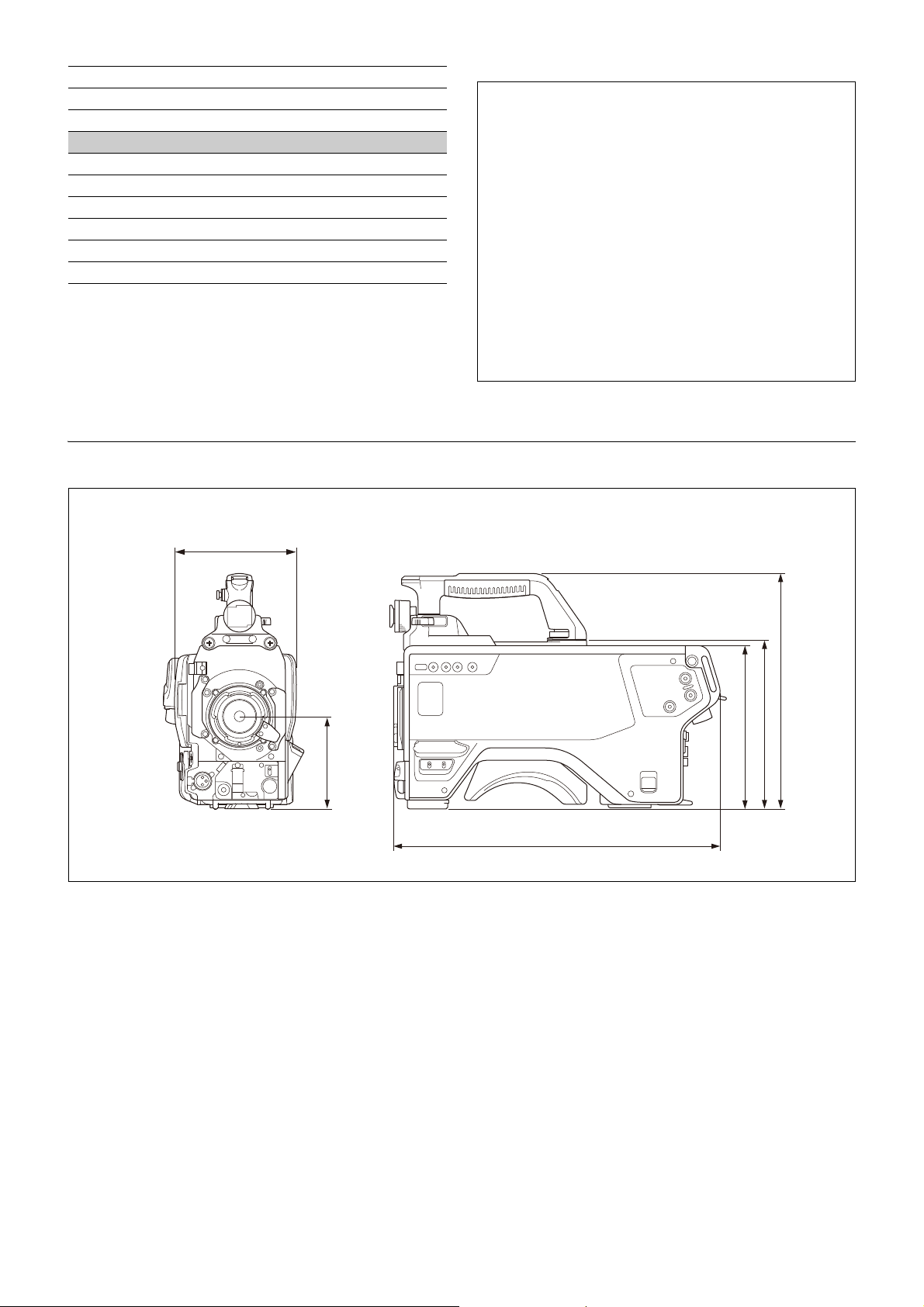
SDI 1D (MCX type)
Unit: mm (inches)
138 (5
1
/2)
*1
363 (14 3/8)
105 (4
1
/
4
)
186 (7
3
/
8
)
192 (7
5
/
8
)
268 (10
5
/
8
)
*1: 152 mm (6 in.) when the HKC-TR37 is installed
SDI 2 (MCX type)
POWER CONNECTOR HD15 (D-Sub 15-pin)
Supplied accessories
Harness (1)
Attachment fittings (1 set)
Nut (1)
Operating Instructions (1)
Rating label (1)
Antenna cushion (1)
Design and specifications are subject to change without
notice.
Dimensions
Notes
• Always verify that the unit is operating properly before
use. SONY WILL NOT BE LIABLE FOR DAMAGES OF ANY
KIND INCLUDING, BUT NOT LIMITED TO,
COMPENSATION OR REIMBURSEMENT ON ACCOUNT OF
THE LOSS OF PRESENT OR PROSPECTIVE PROFITS DUE
TO FAILURE OF THIS UNIT, EITHER DURING THE
WARRANTY PERIOD OR AFTER EXPIRATION OF THE
WARRANTY, OR FOR ANY OTHER REASON
WHATSOEVER.
• SONY WILL NOT BE LIABLE FOR CLAIMS OF ANY KIND
MADE BY USERS OF THIS UNIT OR MADE BY THIRD
PARTIES.
• SONY WILL NOT BE LIABLE FOR THE TERMINATION OR
DISCONTINUATION OF ANY SERVICES RELATED TO THIS
UNIT THAT MAY RESULT DUE TO CIRCUMSTANCES OF
ANY KIND.
Open Source Software Licenses
On the basis of license contracts between Sony and the
software copyright holders, this product uses open
software. To meet the requirements of the software
copyright holders, Sony is obligated to inform you of the
content of these licenses.
For the content of these licenses, see the PDF file in the
“License” folder of the supplied CD-ROM.
Adobe Reader must be installed on your computer to view
PDF files.
About the MPEG-4 Visual Patent Portfolio
License
The MPEG-4 Visual Patent Portfolio License is applicable
only when the HKC-TR37 Triax Transmission Adaptor is
installed.
MPEG-4 Visual Patent Portfolio License
THIS PRODUCT IS LICENSED UNDER THE MPEG-4 VISUAL
PATENT PORTFOLIO LICENSE FOR THE PERSONAL AND
NONCOMMERCIAL USE OF A CONSUMER FOR
(i) ENCODING VIDEO IN COMPLIANCE WITH THE MPEG-4
VISUAL STANDARD (“MPEG-4 VIDEO”)
AND/OR
(ii) DECODING MPEG-4 VIDEO THAT WAS ENCODED BY A
CONSUMER ENGAGED IN A PERSONAL AND NON-
100
 Loading...