

Sony HCD-ZT4 Service Manual
HCD-ZT4
SERVICE MANUAL
Ver. 1.0 2008.06
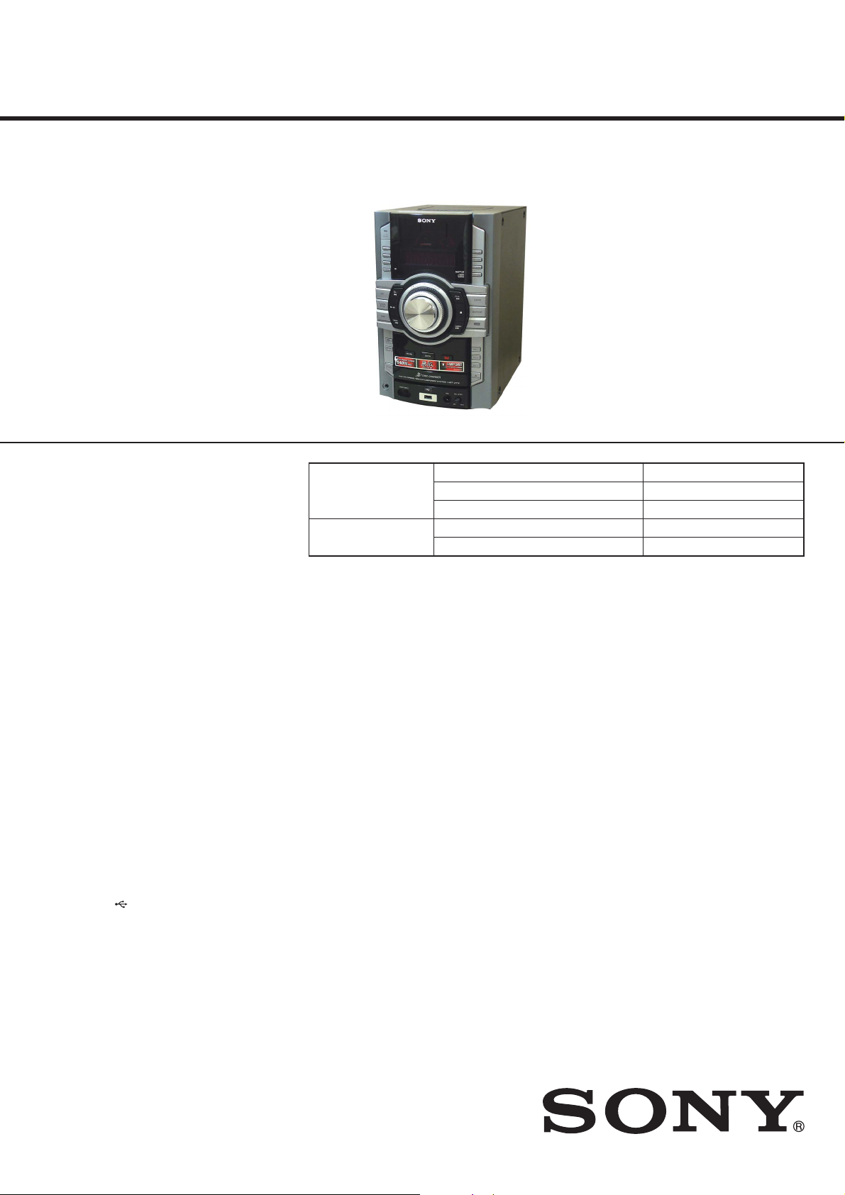
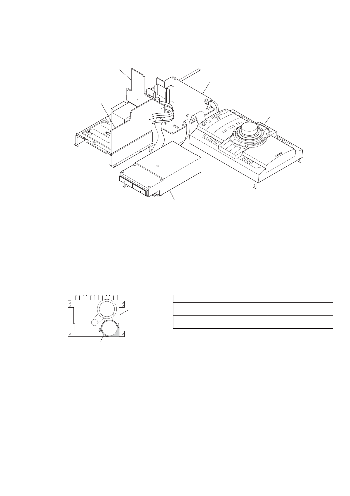
• HCD-ZT4 is the amplifi er, USB, CD player, tape
deck and tuner section in LBT-ZT4.
CD
Section
Tape deck
Section
Model Name Using Similar Mechanism
Mechanism Type
Optical Pick-up Block Name
Model Name Using Similar Mechanism
Tape Transport Mechanism Type
US Model
NEW
CDM88A-K6BD93-WOD
KSM-213DCP
NEW
TCM-J1 or CS-21SC-900TP
AUDIO POWER SPECIFICATION
POWER OUTPUT AND TOTAL
HARMONIC DISTORTION:
With 6 ohm loads, both channels driven,
from 120Hz – 10kHz; rated 110wattsper
channel minimum RMS power, with no
more than 0.7% total harmonic distortion
from 250 miliwatts to rated output.
Amplifier section
The following are measured at AC 120 V
60 Hz
Front speaker
RMS output power (reference):
180W+180W(perchannelat67,
1 kHz, 10% THD)
Subwoofer
RMS output power (reference): 180 W
(at 6 7, 100Hz,10%THD)
Inputs
AUDIO INPUT:sensitivity
800 mV, impedance 47 kilohms
MIC: sensitivity 1 mV, impedance
10 kilohms
(USB) port: Type A
DMPORT
Outputs
PHONES: accepts headphones of 8 7 or
more
FRONT SPEAKER: accepts impedance of
6 7
SUBWOOFER: accepts impedance of 6 7
SPECIFICATIONS
USB section
Supported bit rate
MP3 (MPEG 1 Audio Layer-3):
32 – 320 kbps, VBR
WMA: 32 – 192 kbps, VBR
AAC: 48 – 320 kbps
Sampling frequencies
MP3 (MPEG 1 Audio Layer-3):
32/44.1/48 kHz
WMA: 44.1 kHz
AAC: 44.1 kHz
Transfer speed
Full-Speed
Supported USB device
Mass Storage Class
Maximum current
500 mA
CD player section
System: Compact disc and digital audio
system
Laser Diode Properties
Emission Duration: Continuous
Laser Output*: Less than 44.6 MW
* This output isthe value measurement
at a distance of 200 mm from the
objective lens surface on the Optical
Pick-up Block with 7 mm aperture.
Frequency response: 20 Hz – 20 kHz
Signal-to-noise ratio: More than 90 dB
Dynamic range: More than 88 dB
Tape deck section
Recording system: 4-track 2-channel, stereo
Tuner section
FM stereo, FM/AM superheterodyne tuner
FM tuner section
Tuning range:
87.5 – 108.0 MHz (100 kHz step)
Antenna: FM lead antenna
Antenna terminals: 75 ohms unbalanced
Intermediate frequency: 10.7 MHz
AM tuner section
Tuning range
530 – 1,710 kHz (with 10 kHz tuning
interval)
531 – 1,710 kHz (with 9 kHz tuning
interval)
Antenna: AM loop antenna,externalantenna
terminal
Intermediate frequency: 450 kHz
General
Power requirements
AC 120 V,60 Hz
Power consumption
225 W
Dimensions (w/h/d) (excl. speakers)
Approx. 231 × 361 × 437.5 mm
(91/8×141/4×171/4inch)
Mass (excl. speakers)
10.0 kg (22 lb 1 oz)
Design and specifications are subject to
change without notice.
9-889-196-01
2008F05-1
2008.06
©
COMPACT DISC DECK RECEIVER
Sony Corporation
Audio Business Group
Published by Sony Techno Create Corporation
HCD-ZT4
NOTES ON CHIP COMPONENT REPLACEMENT
• Never reuse a disconnected chip component.
• Notice that the minus side of a tantalum capacitor may be damaged by heat.
FLEXIBLE CIRCUIT BOARD REPAIRING
• Keep the temperature of soldering iron around 270 °C during
repairing.
• Do not touch the soldering iron on the same conductor of the
circuit board (within 3 times).
• Be careful not to apply force on the conductor when soldering
or unsoldering.
CAUTION
Use of controls or adjustments or performance of procedures
other than those specifi ed herein may result in hazardous radia-
tion exposure.
SAFETY CHECK-OUT
After correcting the original service problem, perform the following safety check before releasing the set to the customer:
Check the antenna terminals, metal trim, “metallized” knobs,
screws, and all other exposed metal parts for AC leakage.
Check leakage as described below.
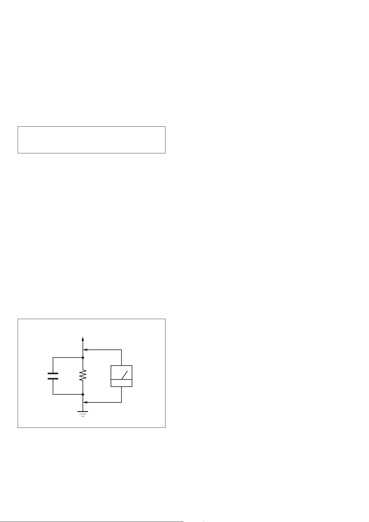
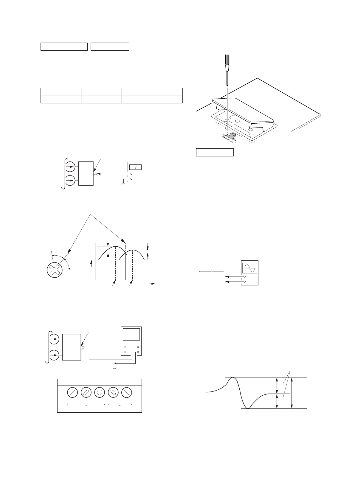
LEAKAGE TEST
The AC leakage from any exposed metal part to earth ground and
from all exposed metal parts to any exposed metal part having a
return to chassis, must not exceed 0.5 mA (500 microamperes.).
Leakage current can be measured by any one of three methods.
1. A commercial leakage tester, such as the Simpson 229 or RCA
WT-540A. Follow the manufacturers’ instructions to use these
instruments.
2. A battery-operated AC milliammeter. The Data Precision 245
digital multimeter is suitable for this job.
3. Measuring the voltage drop across a resistor by means of a
VOM or battery-operated AC voltmeter. The “limit” indication
is 0.75 V, so analog meters must have an accurate low-voltage
scale. The Simpson 250 and Sanwa SH-63Trd are examples
of a passive VOM that is suitable. Nearly all battery operated
digital multimeters that have a 2 V AC range are suitable. (See
Fig. A)
To Exposed Metal
Parts on Set
AC
1.5 kΩ0.15 μF
voltmeter
(0.75 V)
Earth Ground
Fig. A. Using an AC voltmeter to check AC leakage.
SAFETY-RELATED COMPONET WARNING!
COMPONENTS IDENTIFIED BY MARK 0 OR DOTTED LINE
WITH MARK 0 ON THE SCHEMATIC DIAGRAMS AND IN
THE PARTS LIST ARE CRITICAL TO SAFE OPERATION.
REPLACE THESE COMPONENTS WITH SONY PARTS
WHOSE PART NUMBERS APPEAR AS SHOWN IN THIS
MANUAL OR IN SUPPLEMENTS PUBLISHED BY SONY.
2

TABLE OF CONTENTS
HCD-ZT4
1. SERVICING NOTES ............................................. 4
2. GENERAL .................................................................. 8
3. DISASSEMBLY
3-1. Disassembly Flow ........................................................... 10
3-2. Side-L/R Case ................................................................. 11
3-3. Top Panel Block .............................................................. 11
3-4. Tape Mechanism Deck .................................................... 12
3-5. Front Panel Block ........................................................... 12
3-6. DC FAN (M102), Back Panel ......................................... 13
3-7. MAIN Board ................................................................... 13
3-8. CD Mechanism Block ..................................................... 14
3-9. DC Fan (M101), POWERAMP Board ........................... 14
3-10. Base Unit ......................................................................... 15
3-11. OP Base Assy (KSM-213D) ........................................... 15
3-12. Belt (DLM3A) ................................................................ 16
4. TEST MODE ............................................................ 17
5. MECHANICAL ADJUSTMENTS ...................... 20
6. ELECTRICAL ADJUSTMENTS ........................ 21
7. DIAGRAMS
7-1. Block Diagram - CD SERVO, USB Section - ................ 23
7-2. Block Diagram - MAIN Section - ................................... 24
7-3. Block Diagram - AMP Section - ..................................... 25
7-4. Block Diagram
- PANEL, POWER SUPPLY Section - ........................... 26
7-5. Schematic Diagram - CD Board (1/2) - .......................... 28
7-6. Schematic Diagram - CD Board (2/2) - .......................... 29
7-7. Printed Wiring Board - CD Board - ................................ 30
7-8. Printed Wiring Board - TC Board - ................................. 31
7-9. Schematic Diagram - TC Board - ................................... 31
7-10. Printed Wiring Board - USB Board - .............................. 32
7-11. Schematic Diagram - USB Board - ................................. 33
7-12. Printed Wiring Board - DMPORT Board - ..................... 34
7-13. Schematic Diagram - DMPORT Board - ........................ 34
7-14. Printed Wiring Board - MAIN Board - ........................... 35
7-15. Schematic Diagram - MAIN Board (1/4) - ..................... 36
7-16. Schematic Diagram - MAIN Board (2/4) - ..................... 37
7-17. Schematic Diagram - MAIN Board (3/4) - ..................... 38
7-18. Schematic Diagram - MAIN Board (4/4) - ..................... 39
7-19. Printed Wiring Board - POWERAMP Board - ............... 40
7-20. Schematic Diagram - POWERAMP Board - .................. 41
7-21. Printed Wiring Boards - JACK Section - ........................ 42
7-22. Schematic Diagram - JACK Section - ............................ 42
7-23. Printed Wiring Boards - REG Section - .......................... 43
7-24. Schematic Diagram - REG Section - .............................. 43
7-25. Printed Wiring Boards - DISPLAY Board - .................... 44
7-26. Schematic Diagram - DISPLAY Board - ........................ 45
7-27. Printed Wiring Boards - PANEL Section - ..................... 46
7-28. Schematic Diagram - PANEL Section - .......................... 47
7-29. Printed Wiring Board - TRANS2 Board - ....................... 48
7-30. Schematic Diagram - TRANS2 Board - ......................... 49
8. EXPLODED VIEWS
8-1. Case Section .................................................................... 58
8-2. Loading Panel Section .................................................... 59
8-3. DISPLAY Board Section ................................................ 60
8-4. Front Panel Section ......................................................... 61
8-5. Meter Display Assy ......................................................... 62
8-6. Top Panel Section ........................................................... 63
8-7. Back Panel Section ......................................................... 64
8-8. MAIN Board Section ...................................................... 65
8-9. Chassis Section ............................................................... 66
8-10. CD Mechanism Section (CDM88A-K6BD93-WOD) .... 67
9. ELECTRICAL PARTS LIST .............................. 68
3

HCD-ZT4
SECTION 1
SERVICING NOTES
NOTES ON HANDLING THE OPTICAL PICK-UP
BLOCK OR BASE UNIT
The laser diode in the optical pick-up block may suffer electrostatic break-down because of the potential difference generated by the
charged electrostatic load, etc. on clothing and the human body.
During repair, pay attention to electrostatic break-down and also
use the procedure in the printed matter which is included in the
repair parts.
The fl exible board is easily damaged and should be handled with
care.
NOTES ON LASER DIODE EMISSION CHECK
The laser beam on this model is concentrated so as to be focused
on the disc refl ective surface by the objective lens in the optical
pickup block. Therefore, when checking the laser diode emission,
observe from more than 30 cm away from the objective lens.
UNLEADED SOLDER
Boards requiring use of unleaded solder are printed with the leadfree mark (LF) indicating the solder contains no lead.
(Caution: Some printed circuit boards may not come printed with
the lead free mark due to their particular size)
: LEAD FREE MARK
Unleaded solder has the following characteristics.
• Unleaded solder melts at a temperature about 40 °C higher
than ordinary solder.
Ordinary soldering irons can be used but the iron tip has to be
applied to the solder joint for a slightly longer time.
Soldering irons using a temperature regulator should be set to
about 350 °C.
Caution: The printed pattern (copper foil) may peel away if
the heated tip is applied for too long, so be careful!
• Strong viscosity
Unleaded solder is more viscous (sticky, less prone to fl ow)
than ordinary solder so use caution not to let solder bridges
occur such as on IC pins, etc.
• Usable with ordinary solder
It is best to use only unleaded solder but unleaded solder may
also be added to ordinary solder.
RELEASING THE DISC TRAY LOCK
The disc tray lock function for the antitheft of an demonstration
disc in the store is equipped.
Releasing Procedure:
1. Press [I/1] button to turn the power on.
2. Press the [CD] button to select CD function.
3. While pressing the [
seconds).
4. The message “UNLOCKED” is displayed and the disc tray is
unlocked.
] button, press the [Z] button for more 5
x
Note: When “LOCKED” is displayed, the slot lock is not released by
turning power on/off with the [I/1] button.
4
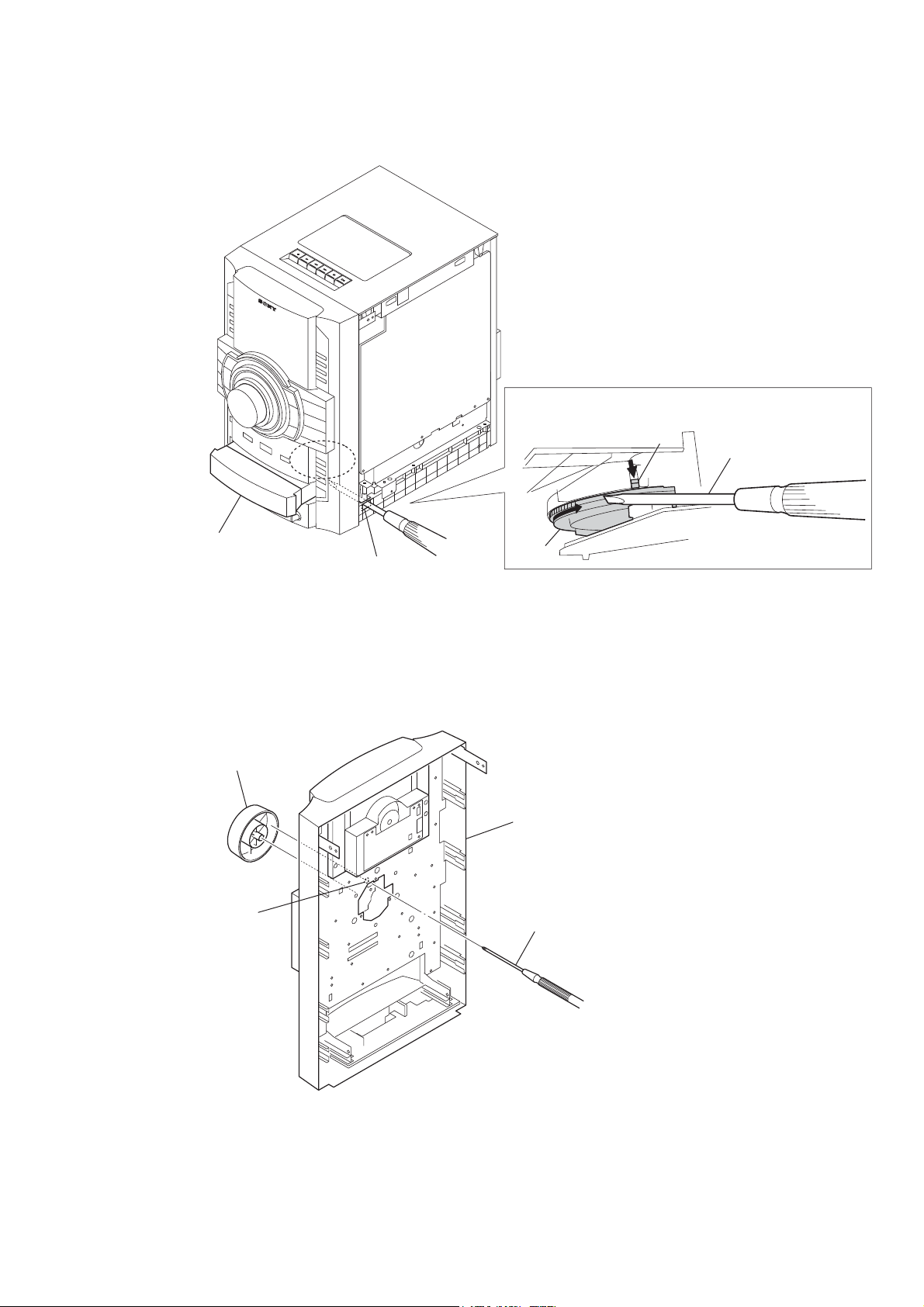
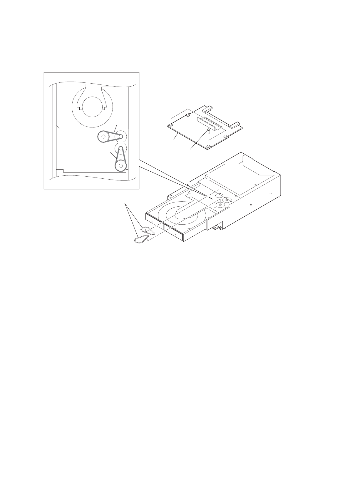
HOW TO OPEN THE TRAY WHEN POWER SWITCH TURN OFF
lever
HCD-ZT4
Turn a gear by
a driver till a lever
falls down to the
position of the figure.
Pull the tray by the hand.
hole
HOW TO REMOVE THE KNOB VOLUME
knob volume
hole
gear
front panel block
(back view)
Push the knob volume by the flat head driver.
5
HCD-ZT4
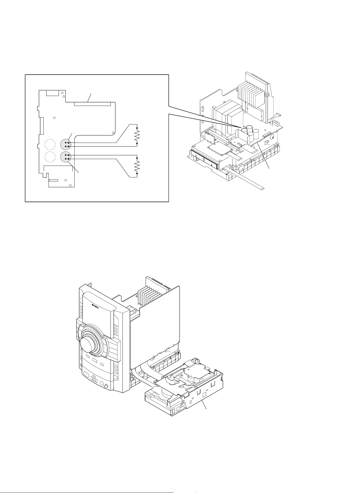
CAPACITOR DISCHARGE FOR ELECTRIC SHOCK PREVENTION
In checking the MAIN board, make a capacitor discharge
of C803 and C804 for electric shock prevention.
POWERAMP board
C803
800 Ω/2W
800 Ω/2W
C804
POWERAMP board
CD MECHANISM BLOCK SERVICE POSITION
CD mechanism block
(bottom view)
6
POWERAMP BOARD SERVICE POSITION
POWERAMP board
TRANS2 board
HCD-ZT4
MAIN board
front panel block
CD mechanism block
HOW TO DISTINGUISH TAPE MECHANISM DECK
Two kinds of tape mechanism decks installed by this set exist.
Please do the repair exchange after confi rming which tape mechanism deck set of the repair according to how to distinguish the fi gure
below.
Tape Deck Name Tape Deck Part No. Belt Part No.
2-670-389-01 BELT (1)
3-214-817-01 BELT (FR)
2-688-621-01 BELT (R/F)
2-688-622-01 BELT (MAIN)
motor
Metal part: TCM-J1
Mold part: CS-21SC-900TP
tape deck
TCM-J1
CS-21SC-900TP
A-1527-851-A
1-797-575-11
7
HCD-ZT4
SECTION 2
GENERAL
This section is extracted
from instruction manual.
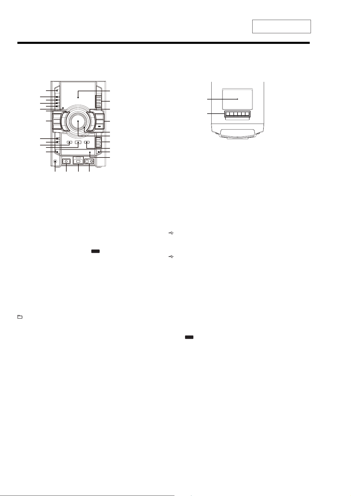
Guide to parts and controls
This manual mainly explains operations using the remote, but the same operations can also be performed using the buttons on the unit having the same or similar names.
Unit
Front view
Top view
CD
TUNER/
BAND
TAPE
*
R
RB
RT
RE
RH
RG
(on/standby)
Press to turn on the system.
The STANDBY indicator lights up when
the system is turned off.
#
DISPLAY
Press to change the information on the
display.
$
METER MODE
Press to select the preset meter display.
%
OPTIONS
Press to change the display, USB and
MP3 BOOSTER+ settings.
&
ERASE
Press to eraseaudio files and folders from
the connected optional USB device.
'
Remote sensor
(
+/– (select folder)
Press to select a folder.
N.(rewind/fast forward)
Press to find a point in a track.
/9(play/pause)
Press to start or pause playback.
Y (stop)
Press to stop playback.
TUNING +/–
Press to tune in the station you want.
(go back/go forward)
Press to select a track or file.
XH
XG
AUDIO
DMPORT
USB
XE
XT
XB
X
RM
RL
RKRI
)
CD
Press to select the CD function.
TUNER/BAND
Press to select the TUNER function.
Press to select the FM or AM band.
TAPE
Press to select the TAPE function.
AUDIO
Press to select the AUDIO function.
USB
Press to select the USB function.
DMPORT
Press to select the DMPORT function.
*
SUBWOOFER
Press to turn on and off the subwoofer.
The SUBWOOFER indicator lights up
when the subwoofer is turned on.
+
REC TIMER
Press to set the Recording Timer.
,
RETURN
Press to return to the parent folder.
Presstoexitsearchmode.
-
NTER
E
Press to enter the settings.
.
DISC SKIP/EX-CHANGE
Press to select a disc. Press to exchange a
disc while playing.
XI
XK
/
PHONES jack
Connect the headphones.
0
AUDIO INPUT jack
Connect to an audio component
(Portable audio player, etc.).
1
(USB) indicator
Lights up in red when transferring to the
connected optional USB device or when
erasing audio files or folders.
(USB) port
Connect an optional USB device.
2
MIC jack
Connect an optional microphone.
MIC LEVEL
Turn to adjust the microphone volume.
3
Disc tray
4
; OPEN/CLOSE
Press to insert or eject a disc.
5
REC TO
Press to transfer onto the connected
optional USB device.
6
DISC 1 – 3
Press toselect a disc.Pressto switch tothe
CD function from other function.
USB
7
MASTER VOLUME
Turn to adjust the volume.
8
OPERATION DIAL
Turn to select a setting in the OPTIONS
menu.
Turn to select a track, file or folder.
9
PRESET EQ
GROOVE, SURROUND
Press to select a sound effect.
EQ BAND
Press to select the frequency band.
:
Display
;
Tape deck
XK
[ (record)
Press to record onto a tape.
# (play)
Press to start tape playback.
*The# button has a tactile dot. Use the tactile
dot as a reference when operating the system.
N.(rewind/fast forward)
Press to rewind/fast forward a tape.
Y; (stop/eject)
Press to stop tape playback.
Press to insert or eject a tape.
9 (pause)
Press to pause tape playback.
8
HCD-ZT4
Remote RM-AMU008
RH
RG
RE
RT
RB
R
Getting Started
(on/standby)
Press to turn on the system.
#
CLEAR
Press to delete the last step from the
program list.
$
EQ
Press to select a sound effect.
%
TIMER MENU
Press to set the clock and the timers.
&
7WC#
Press to select the settings.
Press to enter the selection.
'
TOOL MENU
Press to select themenu of the component
connected to the DIGITAL MEDIA
PORT adapter.
(
(go back/go forward)
Press to select a track or file.
+/– (select folder)
Press to select a folder.
+/– (tuning)
Press to tune in the station you want.
N.(rewind/fast forward)
Press to find a point in a track or file.
/(play)
Press to start playback.
DISC SKIP
Press to select a disc.
9 (pause)
Press to pause playback.
Y (stop)
Press to stop playback.
)
FUNCTION +/–
Press to select a function.
*
VOLUME +/–*
Press to adjust the volume.
* The VOLUME + button has a tactile dot. Use
the tactile dot as a reference when operating
the system.
+
0 RETURN
Press to return to the parent folder.
Press to exit search mode.
,
TUNER MEMORY
Press to preset the radio station.
-
PLAY MODE/TUNING MODE
Press to select the play mode of an
AUDIOCD,MP3discor anoptional
USB device.
Press to select the tuning mode.
.
REPEAT/FM MODE
Presstolistentoadisc,anUSBdevice,a
single track or file repeatedly.
Press to select the FM reception mode
(monaural or stereo).
/
SLEEP
Press to set the Sleep Timer.
0
DISPLAY
Press to change the information on the
display.
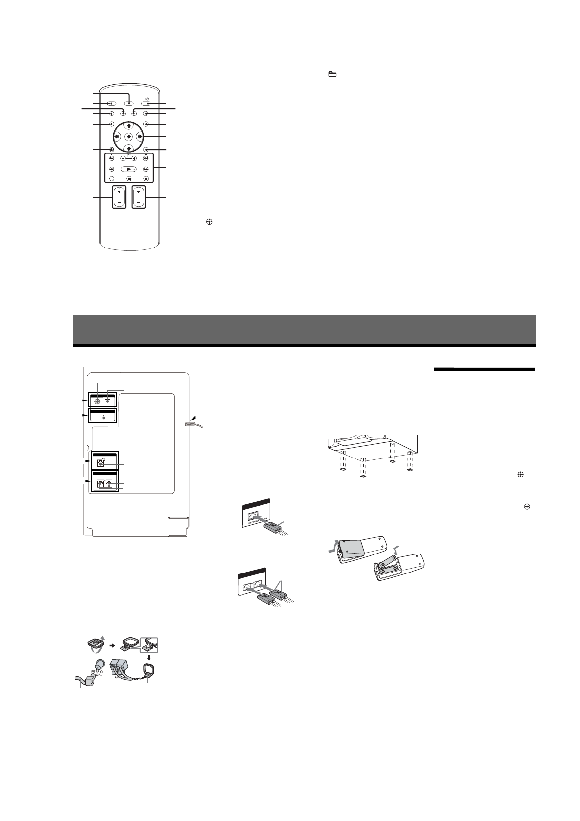
Hooking up the system securely
Notes
ANTENNA
"
DMPORT
#
$
%
To FM lead antenna
To AM loop antenna
To DIGITAL MEDIA PORT adapter
To subwoofer
To front speaker (left)
To front speaker (right)
SUBWOOFER
FRONT SPEAKER
V
" Antennas
Find a location and an orientation that
provide good reception, and then set up
the antennas.
Extend the FM lead
antenna horizontally
Keep the antennas away from the speaker
cords, the power cord and the USB cable
to avoid picking up noise.
# DMPORT (DIGITAL MEDIA PORT)
Connect the DIGITAL MEDIA PORT
adapter. You need to connect the
DIGITAL MEDIA PORT adapter to an
optional audio device (portable audio
player, etc.).
AM loop antenna
• The DIGITAL MEDIA PORT adapters are
• Do not connect an adapter other than the
• When connecting the DIGITAL MEDIA
&
• Do not connect or disconnect the DIGITAL
• When using a DIGIT AL MEDIA PORT
$ Subwoofer
Be sure to insert the connector straight
into the terminals.
% Front speakers
Be sure to insert the connector straight
into the terminals.
& Power
Connect the power cord to a wall socket.
The demonstration appearsin the display.
If the plug does not fit the wall socket,
detach the supplied plug adaptor (only for
models equipped with an adaptor).
When carrying this system
Use the buttons on the unit for this
operation.
1
2
3
4
available for purchase depending on the area.
DIGITAL MEDIA PORT adapter.
PORT adapter, be sure the connector is
inserted with the arrow mark facing towards
the arrow mark on the DMPORT jack.
MEDIA PORTadapter to/from theDMPORT
jack while the system is turned on.
adapter that has video output function,
connect the video output of the adapter
directly to the TV.
SUBWOOFER
Purple
FRONTSPEAKER
R
EDANCE
P
IM
Remove all discs to protect the CD
mechanism.
White
L
6Ω
USE
Press CD to select the CD function.
Hold down DISC SKIP/
EX-CHANGE, and press until
“STANDBY” appears.
After “MECHA LOCK” appears,
unplug the power cord.
Speaker pads
Attach the supplied speaker pads to the
bottom of the front speakers and
subwoofer to prevent slipping.
Front speakers:
4 pads for each speaker
Subwoofer:
4 pads
To use the remote
Slide and remove the battery
compartment lid, then, insert the two
supplied R6 (size AA) batteries, & side
first, matching the polarities shown
below.
Notes
• With normal use, the batteries should l ast for
about six months.
• Do not mix an old battery with a new on e or
mix different types of batteries.
• If you do not use the remote for a long period
of time, remove thebatteries to avoid damage
from battery leakage and corrosion.
Setting the clock
You cannot set the clock in PowerSaving
Mode.
Use the buttons on the remote for this
operation.
1 Press to turn on the system.
2 Press TIMER MENU (RM-AMU008).
If “PLAY SET” appears on the
display, press
(RM-AMU008) repeatedly to select
“CLOCK SET” and then press
(RM-AMU008).
3 Press
7W(RM-AMU008) repeatedly to
set the hour, and then press
(RM-AMU008).
4 Use the same procedure to set
the minutes.
The clock settings are lost when you
disconnect the power cord or if a
power failure occurs.
To display the clock when the
system is turned off
Press DISPLAYrepeatedly until theclock
is displayed. The clock is displayed for
about 8 seconds.
7W.
9

HCD-ZT4
DISASSEMBLY
• This set can be disassembled in the order shown below.
3-1. DISASSEMBLY FLOW
SET
3-2. SIDE-L/R CASE
(Page 11)
3-3. TOP PANEL BLOCK
(Page 11)
SECTION 3
3-5. FRONT PANEL BLOCK
(Page 12)
3-6. DC FAN (M102), BACK PANEL
(Page 13)
3-7. MAIN BOARD
(Page 13)
3-9. DC FAN (M101),
POWERAMP BOARD
(Page 14)
3-4. TAPE MECHANISM DECK
(Page 12)
3-8. CD MECHANISM BLOCK
(Page 14)
3-10. BASE UNIT
(Page 15)
3-11. OP BASE ASSY (KSM-213D)
(Page 15)
3-12. BELT (DLM3A)
(Page 16)
10
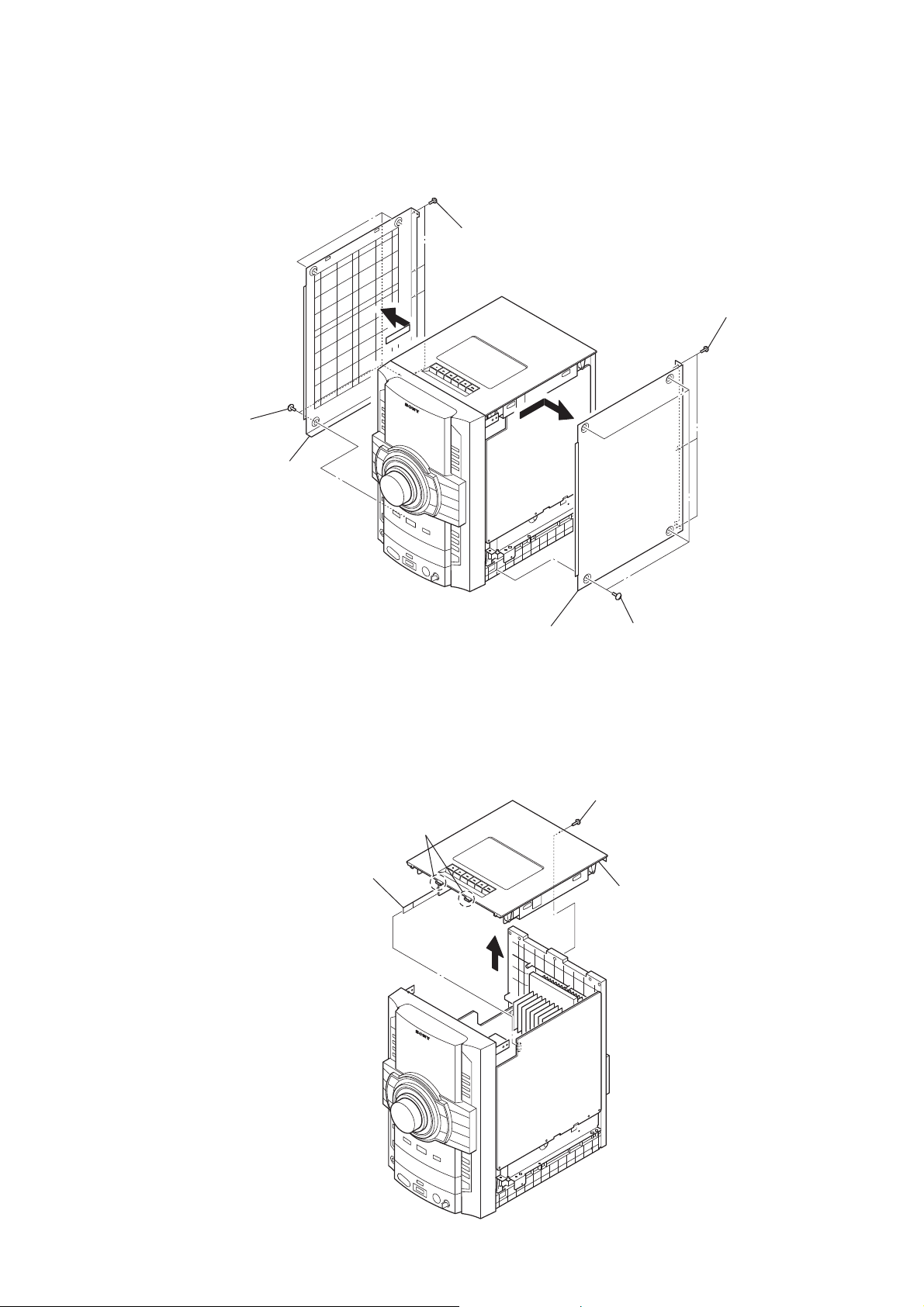
Note: Follow the disassembly procedure in the numerical order given.
3-2. SIDE-L/R CASE
four screws
(case 3 TP2)
side-L case
four screws
(BVTP3 × 10)
HCD-ZT4
three screws
(BVTP3 × 10)
3-3. TOP PANEL BLOCK
flexible flat cable
(CN450)
two claws
side-R case
four screws
(case 3 TP2)
screw
(BVTP3 × 10)
top panel block
11
HCD-ZT4
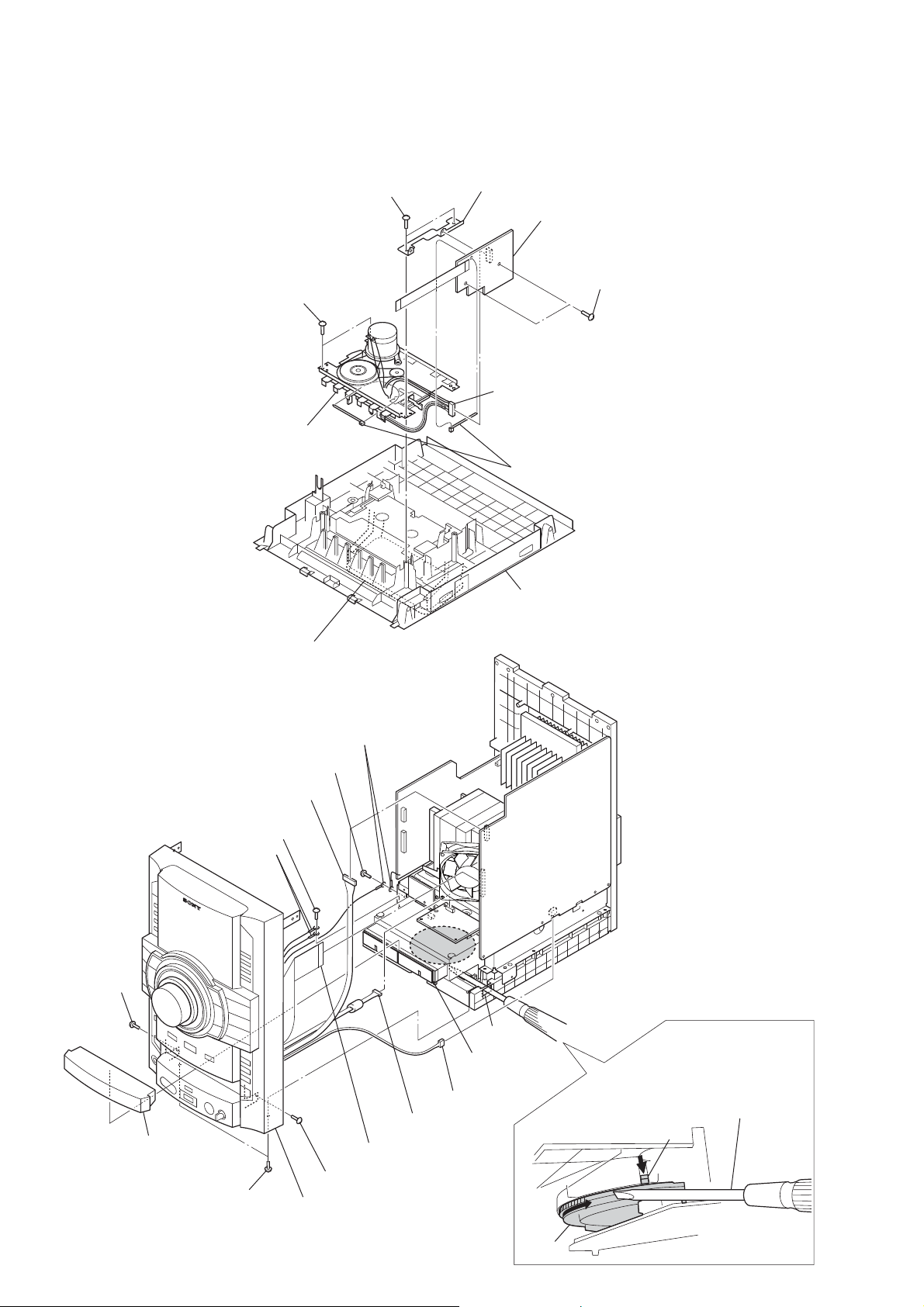
3-4. TAPE MECHANISM DECK
Note: This illustration is seeing top panel block from inside.
two screws
(BVTP2.6 × 8)
two screws
(BVTP2.6 × 8)
tape mechanism deck
bracket (deck)
connector (CN501)
Cut the two clamps.
TC board
two screws
(BVTP3 × 8)
Open the cassette box.
3-5. FRONT PANEL BLOCK
RT
(BVTP3 × 10)
connector (CN470)
screw
(BVTP3 × 10)
two harness
RB
screw
(BVTP3 × 10)
panel loading
screw
two harnesses
RE
Pull the
tray by hand.
connector (CN488)
connector (CN903)
flexible flat cable (CNCN403)
top panel block
hole
Turn a gear by
a driver till a lever
falls down to the
position of the figure.
lever
12
two screws
(BVTP3 × 10)
screw (BVTP3 × 10)
front panel block
RG
gear
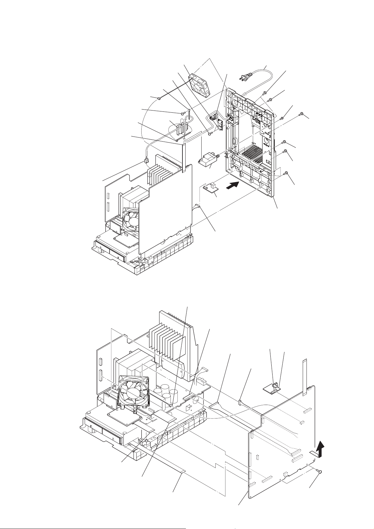
3-6. DC FAN (M102), BACK PANEL
RH
bushing bracket
two screws (BVTP3 × 10)
X
XB
DC fan (M102)
cord
XT
bushing
power cord
XE
two screws
RG
(BVTP3 × 12)
HCD-ZT4
RI
flexible flat cable
(9 core)
power cord connector
(CN901)
RK
fan connector (CN690)
screw (BVTP3 × 10)
Cut the clamp.
RL
coating clip
ferrite core
RM
tuner
RE
(FM/AM)
SW JACK
RB
board
connector
(CN890)
R
back panel
XG
screw
(BVTP3 × 8)
two screws
RT
(BVTP3 × 10)
(BVTP3 × 10)
screw
(BVTP3 × 10)
screw
(BVTP3 × 10)
five screws
(BVTP3 × 10)
screw
3-7. MAIN BOARD
flexible flat cable (21 core)
(CN420)
wire (flat type) (31 core)
(CN430)
wire (flat type) (13 core)
(CN410)
fan connector
(CN110)
connector
(CN801)
connector
(CN907)
MAIN board
RT
R
(CN1301)
connector
(CN055)
connector
DMPORT board
RB
two screws
(BVTP3 × 10)
13
HCD-ZT4
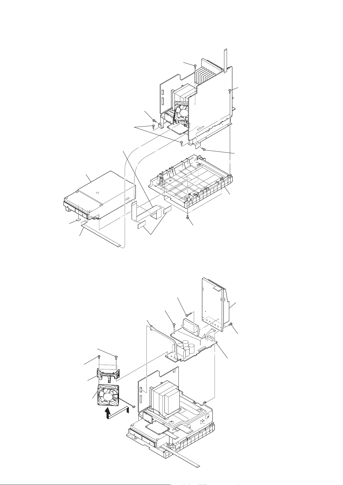
3-8. CD MECHANISM BLOCK
wire (flat type) (31 core)
(MAIN board: CN430/
CD board: CN201)
CD mechanism block
RT
screw
(BVTP3 × 10)
two screws
(BVTP3 × 10)
screw
(BVTP3 × 10)
two screws
(BVTP3 × 10)
screw
(BVTP3 × 10)
three sheets
RB
wire (flat type) (13 core)
(MOTOR board/
MAIN board: CN410)
Note: When installing the CD mechanism section,
install two tapes for prevention of noise.
3-9. DC FAN (M101), POWERAMP BOARD
connector (CN903)
two screws
(BVTP3 × 10)
two screws
(BVTP3 × 12)
two saranet cushions
two screws
(transistor)
three screws
(BVTP3 × 10)
four screws
(BVTP3 × 10)
chassis
heat sink block
two screws
(BVTP3 × 10)
POWERAMP board
RB
14
bracket (fan)
DC fan (M101)
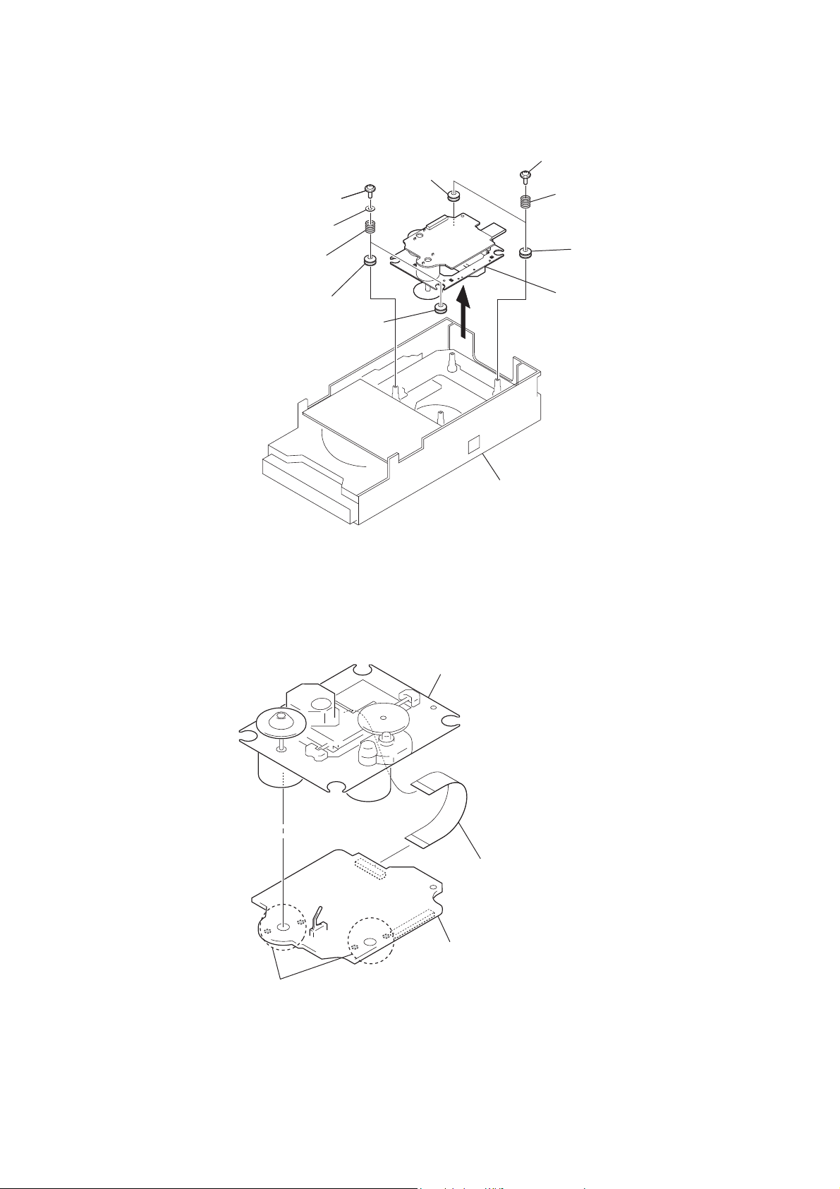
3-10. BASE UNIT
two screws (PTPWHM2.6)
two polyethylene washers
HCD-ZT4
two screws (PTPWHM2.6)
insulator
two springs
(insulator)
insulator
two springs (insulator)
insulator
insulator
– Bottom view –
3-11. OP BASE ASSY (KSM-213D)
CD mechanism block
OP base assy
(KSM-213D)
base unit
Remove four solders.
flexible flat cable (16 core)
(CD board: CN301/optical pick-up block)
CD board
15
HCD-ZT4
3-12. BELT (DLM3A)
position of belt
belt
cover
belt
two belts (DLM3A)
four screws
16

SECTION 4
TEST MODE
HCD-ZT4
PANEL TEST MODE
This mode is used to check the fl uorescent indicator tube, LEDs,
keys, [MASTER VOLUME] jog, [OPERATION DIAL] jog, model, destination and software version.
Procedure:
1. Press [x] button, [METER MODE] button and [DISC 2] button simultaneously.
2. All LEDs and segments in fl uorescent indicator tube are lighted
up. The POWER LED is lighted up in red color if the system is
turned off and POWER LED is turn off if the system is turned
on.
3. When you want to enter to the software version display mode,
press [DISC 1] button. The model information appears on the
fl uorescent indicator tube. The message “GSL 2RS” appears
on the fl uorescent indicator tude. Press [DISC 1] button again
to view the destination information.
4. During the destination information display, press [DISC 1]
button. Each time [DISC 1] button is pressed, the fl uorescent
indicator tube shows the version of each category software in
the following sequence: SC, GC, SYS, CD, CDDM, CDMA,
CDMB, BDA, BDB, ST, TC, TA, TM, MM1, MM2 (USB
Micro computer) , MTR (METER) and return back to model
information display.
5. When [DISC 3] button is pressed while the version numbers
are being displayed except model and destination, the date
of the software creation appears. When [DISC 3] button is
pressed again, the display returns to the software version display. When [DISC 1] button is pressed while the date of the
software creation is being displayed, the date of the software
creation is displayed in the same order of software version display.
6. Press [DISC 2] button, the key check mode is activated.
7. In the key check mode, the fl uorescent indicator tube displays
“K 0 J0 V0”.
Each time a button is pressed, “K” value increases. However,
once a button has been pressed, it is no longer taken into account.
“V” value increases in the manner of 0,1, 2, 3 ... if [MASTER
VOLUME] knob is turned clockwise, or it decreases in the
manner of 0, 9, 8,7 ... if [MASTER VOLUME] knob is turned
counterclockwise.
“J” value increases in the manner of 0,1, 2, 3 ... if [OPERA-
TION DIAL] knob is turned clockwise, or it decreases in the
manner of 0, 9, 8,7 ... if [OPERATION DIAL] knob is turned
counterclockwise.
8. When [DISC SKIP/EX-CHANGE] button is pressed after all
LEDs and segments in fl uorescent indicator tube light up, al-
ternate segments in fl uorescent indicator tube and LEDs would
light up. If you press [DISC SKIP/EX-CHANGE] button
again, another half of alternate segments in fl uorescent indica-
tor tube and LEDs would light up. Pressing [DISC SKIP/EXCHANGE] button again would cause all segments in fl uores-
cent indicator tube and LEDs light up.
9. To release from this mode, press three buttons in the same
manner as step 1, or disconnect the power cord.
COMMON TEST MODE
This mode is used to check operations of the respective sections of
Amplifi er and Tape.
To enter Common Test Mode
Procedure:
1. Press [x] button, [METER MODE] button and [DISC 3] button simultaneously.
2. The CD ring indicators fl ash on the fl uorescent indicator tube.
The function is changed to AUDIO and the volume is changed
to VOLUME MIN.
Check of Amplifi er
Procedure:
1. Press [EQ BAND] button repeatedly until a message “GEQ
MAX” appears on the fl uorescent indicator tube. GEQ increas-
es to its maximum.
2. Press [EQ BAND] button repeatedly until a message “GEQ
MIN” appears on the fl uorescent indicator tube. GEQ decreas-
es to its minimum.
3. Press [EQ BAND] button repeatedly until a message “GEQ
FLAT” appears on the fl uorescent indicator tube. GEQ is set to
fl at.
4. When the [MASTER VOLUME] knob is turned clockwise
even slightly, the sound volume increases to its maximum and
a message “VOLUME MAX” appears on the fl uorescent indi-
cator tube.
5. When the [MASTER VOLUME] knob is turned counterclockwise even slightly, the sound volume decreases to its minimum
and a message “VOLUME MIN” appears on the fl uorescent
indicator tube.
Tape function
When a tape is inserted in deck and recording is started, the function is changed to AUDIO.
To release from Common Test mode
Procedure:
1. To release from this mode, press [
2. The cold reset is enforced at the same time.
?/1
] button.
COLD RESET
The cold reset clears all data including preset data stored in the
EEPROM to initial conditions. Execute this mode when returning
the set to the customer.
Procedure:
1. Press [
2. Press [x] button, [ENTER] button, and [
neously.
3. “COLD RESET” appears on the fl uorescent indicator tube.
After that, the fl uorescent indicator tube becomes blank for a
while, and the system is reset.
] button to turn on the system.
?/1
] button simulta-
?/1
VACS ON/OFF
This mode is used to switch ON and OFF the VACS (Variable Attenuation Control System).
Procedure:
1. Press [
2. Press [x] button, [DISC 2], and [DISPLAY] button simultaneously. The message “VACS OFF” or “VACS ON” appears on
the fl uorescent indicator tube.
] button to turn on the system.
?/1
17

HCD-ZT4
TUNER STEP CHANGE
The step interval of AM channels can be toggled between 9 kHz
and 10 kHz. This mode is not available for Saudi Arabian, European and Russian models.
Procedure:
1. Press [
] button to turn on the system.
?/1
2. Press [TUNER/BAND] button repeatedly to select the “AM”.
3. Press [
4. Press [ENTER] button and [
] button to turn off the system.
?/1
?/1
] button simultaneously. The
system turns on automatically. The message “AM 9K STEP”
or “AM 10K STEP” appears on the fl uorescent indicator tube
and thus the channel step is changed.
CD SERVICE MODE
This mode let you move the CD sled motor freely. Use this mode
when you want to clean the optical pick-up.
Procedure:
1. Press [
2. Press [CD] button to select CD function.
3. Press [x] button, [METER MODE] button, and [OPEN/
CLOSE] button simultaneously.
4. The CD service mode is activated. The message “SERVICE
MODE” appears on the fl uorescent indicator tube.
5. With the disc in stop status, press [M] to move the optical
pick-up to outside track, or press [m] to move to inside track.
The message “SLED OUT” or “SLED IN” appears on the fl uo-
rescent indicator tube.
6. To turn on or off the laser, press [>] button. The message
“LD ON” or “LD OFF” appears on the fl uorescent indicator
tube.
7. To release from this mode, press [
] button to turn on the system.
?/1
?/1
] button.
• Aging mode sequence:
START (from
Disc 1)
Disc Chucking
TOC Reading
Play first track for 2
seconds
Play last track for 2
seconds
EX-CHANGE open/
close
CD AGING MODE
This mode can be used for operation check of CD section.
If an error occurs, the aging operation would stops and the status is
displayed. If there were no error occurs, the aging operation would
continue repeatedly.
Procedure:
1. Press [
2. Select CD function.
3. Load three discs on the disc tray.
4. Press [PLAY MODE/TUNING MODE] button on the remote
repeatedly to select the “ALL DISCS” mode, and press the
[REPEAT/FM MODE] button on the remote repeatedly to select “REPEAT OFF” mode.
5. Press [x] button, [METER MODE] button and [DISC SKIP/
EX-CHANGE] button simultaneously.
6. Aging operation is started.
7. To release from this mode, press [
power cord to turn off the system.
] button to turn on the system.
?/1
] button or disconnect the
?/1
Open the disc tray
Disc skip
Close the disc tray
Change the disc tray
CD ERROR CODE MODE
Display the CD error code when an error occurred
Procedure:
1. Press [x] button, [METER MODE] button and [DISC 1] button simultaneously to enter the error code display mode.
2. The fl uorescent indicator tube displays the number of total er-
ror.
3. Each time [m] or [M] button is pressed, display change as
below.
18

HCD-ZT4
Display of
Total Error
FF button FR button
AMS (+)
button
FF button
AMS (+)
button
Display of
Mechanical
Errors
Display of
No Disc
Errors
AMS (–)
button
FR button
AMS (–)
button
4. To clear the error record, operate the cold reset. (Refer to the
“COLD RESET”)
5. To release from this mode, press the [
] button or disconnect
?/1
the power plug to turn off the system.
• Display of total error
EM**ED**
EM** : The number of mechanical errors.
ED** : The number of no disc errors after chucking the disc.
• Display of mechanical errors
M*
M* : The number of mechanical error (“0” is latest one)
(Press [>] button to display the next error)
• Display of no disc errore
CD REPEATS 5 LIMIT OFF MODE
The number of repeat for CD playback is 5 times when the repeat
mode is “REPEAT ALL”. This mode enables CD to repeat playback for limitless times.
Procedure:
1. Press [
] button to turn on the system.
?/1
2. Select CD function.
3. Press [x] button, [CD] button and [DISC 1] button simultane-
ously to enter the CD repeat 5 limit off mode and the fl uores-
cent indicator tube displays “LIMIT OFF”.
4. To release from this mode, operate the cold reset. (Refer to the
“COLD RESET”)
CD SHIP MODE (WITH MEMORY CLEAR)
This mode moves the optical pick-up to the position durable to
vibration and clears all data including preset data stored in the EEPROM to initial conditions during the next AC-In. Use this mode
when returning the set to the customer after repair.
Procedure:
1. Press [
] button to turn on the system.
?/1
2. Select CD function.
3. Press [x] button, [DISC 1] button and [
] button simultane-
?/1
ously. The system turns off automatically.
4. After the “STANDBY” blinking display fi nishes, a message
“MECHA LOCK” is displayed on the fl uorescent indicator
tube and the CD ship mode is set.
CD SHIP MODE (WITHOUT MEMORY CLEAR)
This mode moves the optical pick-up to the position durable to
vibration. Use this mode when returning the set to the customer
after repair.
Procedure:
1. Press [
2. Select CD function.
3. Press [DISC SKIP/EX-CHANGE] button and [
multaneously. The system turns off automatically.
4. After the “STANDBY” blinking display fi nishes, a message
“MECHA LOCK” is displayed on the fl uorescent indicator
tube and the CD ship mode is set.
] button to turn on the system.
?/1
] button si-
?/1
D*$$%%&&##00
D* : The number of no disc error (“0” is latest one)
(Press [>] button to display next error)
$$ : Error type
01 : Focus error
02 : GFS error
03 : Setup error
%% : Not used
&& :
00 : No disc judgment without chucking retry.
01 : No disc judgment after chucking retry.
## : The state when judged as no disc
01 : Stop
02 : Setup
03 : TOC reading
04 : Access
05 : Playback
06 : Pause
07 : Manual search (Play)
08 : Manual search (Pause)
CD TRAY LOCK MODE
This mode let you lock the disc tray. When this mode is activated,
the disc tray will not open when [OPEN/CLOSE] button or [DISC
SKIP/EX-CHANGE] button is pressed. The message “LOCKED”
will be displayed on the fl uorescent indicator tube.
Procedure:
1. Press [
] button to turn on the system.
?/1
2. Select CD function.
3. Press [x] button and [OPEN/CLOSE] button simultaneously
and hold down until “LOCKED” or “UNLOCKED” displayed
on the fl uorescent indicator tube (around 5 seconds).
FACTORY PRESET
This mode is use to load all the factory use preset frequencies into
FM 1-FM 20 and AM 1-AM 10. Originally, frequency of FM 1FM 20 and AM 1-AM10 are set to the minimum frequency.
Procedure:
1. Press [
2. Press [TUNER/BAND] button, [x] button, and [DISC 1] button simultaneously and the message “FACTORY” appears
on the fl uorescent indicator tube. The function is changed to
TUNER automatically.
] button to turn on the system.
?/1
19

HCD-ZT4
SECTION 5
MECHANICAL ADJUSTMENTS
VACS DISPLAY
This mode is used to check the VACS level.
Procedure:
1. Press [
] button to turn on the system.
?/1
2. Press [ERASE] button, [x] button and [ENTER] button si-
multaneously.
3. The fl uorescent indicator tube displays “VACSA”. “A” repre-
sents Conventional VACS (Triggered by signal level)
4. To release from this mode, do the step 2 again.
METER SWITCH TOUCH COUNT DISPLAY
This mode is used to display the total count of meter pointer touch
initial switch and max switch.
Procedure:
1. Press [
] button to turn on the system.
?/1
2. Press [x] button, [ENTER] button and [DISPLAY] button simultaneously.
3. The fl uorescent indicator tube displays “IxxxxxMyyyyy”.
“I” represents the Initial Switch touch.
“xxxxx” represents the total count of Initial Switch touch.
(Maximum Value of “xxxxx” = 65535)
“M” represents the Max Switch touch.
“yyyyy” represents the total count of Max Switch touch.
(Maximum Value of “yyyyy” = 65535)
4. To release from this mode, do the step 2 again. The fl uorescent
indicator tube displays “MODE OUT”.
METER TEST MODE
This mode is used to check the meter device.
Procedure:
1. Press [
2. Press [x] button, [ENTER] button and [METER MODE] button simultaneously and the message “TST MODE IN” appears
on the fl uorescent indicator tube.
3. Meter Backlight LEDs, Meter Pointer LEDs, Power Illuminator LEDs and fl uorescent indicator tube are lighted up.
4. When you want to perform count total step from Initial Switch
to Max Switch operation mode, press [M] button. The meter pointer will move from Initial Switch to Max Switch and
fi nally move back to the middle position. The total step count
information appears on the fl uorescent indicator tube. “xxx
STP yy” is shown.
“xxx” represents the total step.
(Value of “xxx” should between 430 steps to 470 steps)
“yy” represents the status of total step count.
(If total step between 430 steps to 470 steps, “yy” is OK, Else
“yy” is NG)
5. When you want to perform count total step from Max Switch
to Initial Switch operation mode, press [m] button. The meter pointer will move from Max Switch to Initial Switch and
fi nally move back to the middle position. The total step count
information appears on the fl uorescent indicator tube. “xxx
STP yy” is shown.
“xxx” represents the total step.
(Value of “xxx” should between 430 steps to 470 steps)
“yy” represents the status of total step count.
(If total step between 430 steps to 470 steps, “yy” is OK, else
“yy” is NG).
6. To release from this mode, do the step 2 again. The fl uorescent
indicator tube displays “TST MODE OUT”.
] button to turn on the system.
?/1
PRECAUTION
1. Clean the following parts with a denatured-alcohol-moistened
swab :
record/playback head pinch roller
erase head rubber belts
capstan idlers
2. Demagnetize the record/playback head with a head demagnetizer. (Do not bring the head magnetizer close to the erase
head.)
3. Do not use a magnetized screwdriver for the adjustments.
4. After the adjustments, appiy suitable locking compound to the
parts adjusted.
5. The adjustments should be performed with the rated power
supply voltage unless otherwise noted.
• Torque Measurement
Mode Torque Meter Meter Reading
FWD CQ-102AS
FWD
Back Tension
FF CQ-201AS
REV CQ-201B
CQ-102C
2.0 – 8.0 mN • m
(20 to 80 g • cm)
(0.28 – 1.12 oz • inch)
0.15 – 0.6 mN • m
(1.5 to 6 g • cm)
(0.021 – 0.083 oz • inch)
5 – 17.7 mN • m
(50 to 177 g • cm)
(0.7 – 2.48 oz • inch)
5 – 17.7 mN • m
(50 to 177 g • cm)
(0.7 – 2.48 oz • inch)
• Tape Tension Measurement
Mode Tension Meter Meter Reading
FWD CQ-403A
more than 80 g
(more than 2.82 oz)
20
SECTION 6
ELECTRICAL ADJUSTMENTS
HCD-ZT4
DECK SECTION 0 dB = 0.775V
1. Demagnetize the record/playback head with a head demagnetizer.
2. Do not use a magnetized screwdriver for the adjustments.
TEST TAPE
Tape Signal Used for
P-4-A063 6.3 kHz, -10 dB Azimuth Adjustment
RECORD/PLAYBACK HEAD AZIMUTH ADJUSTMENT
Procedure:
1. Mode: Playback
test tape
P-4-A063
(6.3 kHz, −10 dB)
MIC board
PHONES jack
(J702)
set
level meter
+
–
2. Turn the adjustment screw and check output peaks. If the peaks
do not match for L-CH and R-CH, turn the adjustment screw
so that outputs match within 1dB of peak.
Output
level
within
1 dB
L-CH
peak
R-CH
peak
within
1 dB
Screw
position
L-CH
peak
Screw
position
R-CH
peak
3. Mode: Playback
test tape
P-4-A063
(6.3 kHz, −10 dB)
set
MIC board
PHONES jack
(J702)
oscilloscope
H
V
Adjustment Location: Record/Playback/Erase Head
CD SECTION
Note:
1. CD Block is basically designed to operate without adjustment. Therefore, check each item in order given.
2. Use YEDS-18 (PART No. 3-702-101-01) unless otherwise indicated.
3. Use an oscilloscope with more than 10MΩ impedance.
4. Clean the object lens by an applicator with neutral detergent when the
signal level is low than specifi ed value with the following checks.
TEST DISC LIST
Use the following test disc on electrical checks.
YEDS-18 (PART No. 3-702-101-01) or
PATD-012 (PART No. 4-225-203-01)
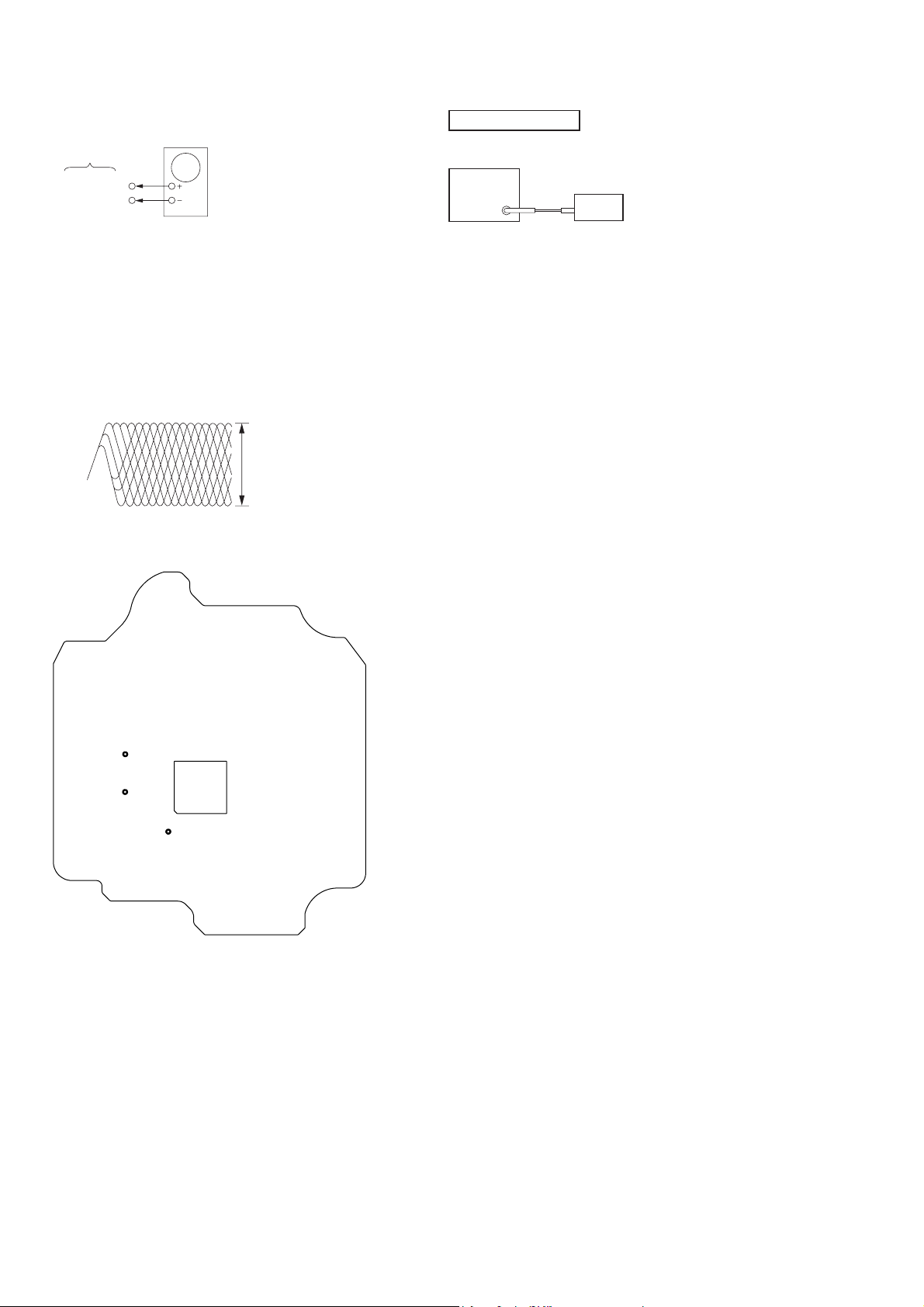
S-CURVE CHECK
oscilloscope
(DC range)
CD board
TP106 (FE)
TP124 (VC)
+
–
Procedure:
1. Connect an oscilloscope to TP106 (FE) and TP124 (VC).
2. Turn the power ON.
3. Load a disc (YEDS-18) and actuate the focus search. (In consequence of open and close the disc tray, actuate the focus
search)
4. Confi rm that the oscilloscope waveform (S-curve) is symmet-
rical between A and B. And confi rm peak to peak level within
1.8 ± 0.5 Vp-p.
waveform of oscilloscope
in phase 45° 90° 135° 180°
good
wrong
4. After the adjustments, apply suitable locking compound to the
pats adjusted.
S-curve waveform
symmetry
A
within 1.8 ± 0.5 Vp-p
B
Note:
• Try to measure several times to make sure than the ratio of A : B or B
: A is more than 10 : 7.
• Take sweep time as long as possible and light up the brightness to
obtain best waveform.
21
HCD-ZT4
RF LEVEL CHECK
oscilloscope
CD board
TP123 (RFO)
TP124 (VC)
Procedure:
1. Connect an oscilloscope to TP123 (RFO) and TP124 (VC).
2. Turn the power ON.
3. Load a disc (YEDS-18) and playback.
4. Confi rm that oscilloscope waveform is clear and check if RF
signal level is correct or not.
Note: Clear RF signal waveform means that the shape “◊” can be clearly
distinguished at the center of the waveform.
RF signal waveform
VOLT/DIV : 200 mV
TIME/DIV : 500 ns
level : 1.3 ± 0.3 Vp-p
Connecting Location: CD board
– CD Board (Conductor Side) –
TUNER SECTION
FM TUNE LEVEL CHECK
signal
generator
set
Procedure:
1. Turn on the set.
2. Input the following signal from signal generator to FM antenna
input directly.
Carrier Freq : A = 87.5 MHz, B = 98 MHz, C = 108 MHz
Deviation : 75 kHz
Modulation : 1 kHz
ANT input : 35 dBu (EMF)
Note: Use 75 ohm coaxial cable to connect signal generator and the set.
You cannot use video cable for checking.
Use signal generator whose output impedance is 75 ohm.
3. Set to FM tuner function and tune A, B and C signals.
4. Confi rm “TUNED” is lit on the display for A, B and C sig-
nals.
When the selected station signal is received in good condition,
“TUNED” is displayed.
TP124 (VC)
TP123 (RFO)
TP106 (FE)
IC101
22
HCD-ZT4
HCD-ZT4
2323
SECTION 7
DIAGRAMS
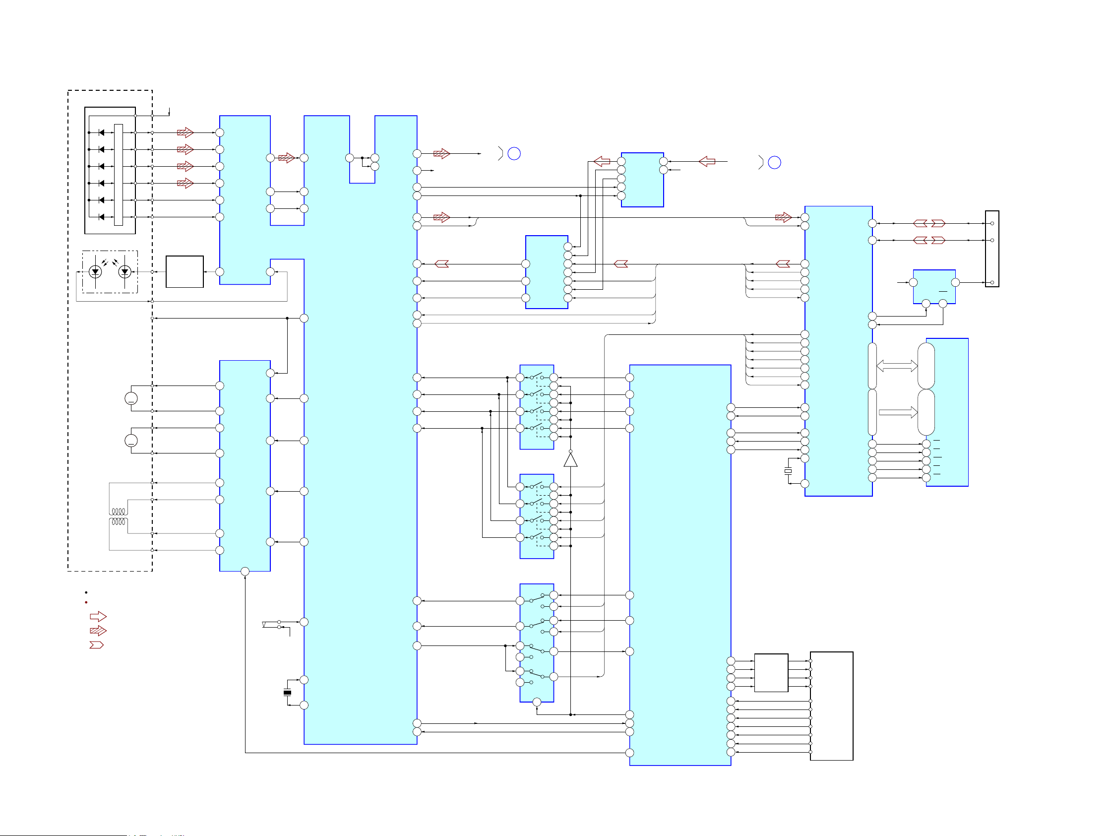
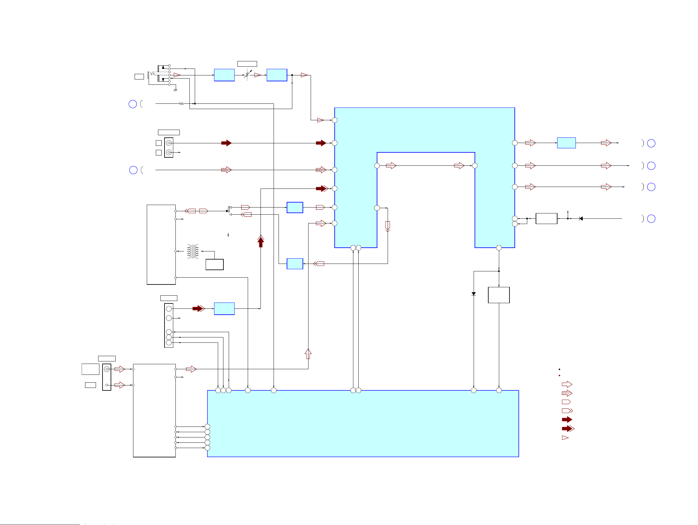
7-1. BLOCK DIAGRAM - CD SERVO, USB Section -
SYSTEM CONTROLLER
IC401 (1/4)
CD-MP3 PROCESSOR
IC101
MUTE
2-AXIS
DEVICE
(TRACKING)(FOCUS)
95
89
A
+3.3V
DETECTOR
FNi1 (A)
RFo
97 FPi1 (B)
88
2
AGCi
3RFRP RFZi
76TEi TEZi
83RFEQo 81 RFi
82 RFRPi
30LO
27RO
46AoUT3 (PO4)
50PIO2
65AIN (PI4)
66BCKi (PI5)
BCK
A-IN
BUS1-U
BUS0-U
BUS2-U
BUS3-U
BUCK-U
67LRCKi (PI6)
LRCK
51PIO3
GATE
49PIO1
ST-REQ
38BUS0
R-CH
94 FNi2 (C)
96 FPi2 (D)
100 TNi (E)
98 TPi (F)
91 LDo 92MDi
2VO1+
1VO1–
13 DMo
LD
PD
LASER DIODE
OPTICAL PICK-UP
BLOCK
(KSM-213DCP)
B
C
D
E
F
12 FMo
10 TRo
9FOo
20 IO0 (/HSO)
I-V AMP
M401
(SPINDLE)
M402
(SLED)
12 VO2–
11 V O2+
18 VO3+
17 VO3–
26 VO4+
27
7
IN4’
24
IN3’ 20
IN2’
9
IN1
3
BIAS
23
84 VRo
VO4–
M
M
FOCUS/TRACKING COIL DRIVE,
SLED/SPINDLE MOTOR DRIVE
IC401
S201
(LIMIT)
+3.3V
24 XO
23 XI
X102
16.9344MHz
47 CD-MMUTE
CD-L
R-CH
USB_REC-L
: CD PLAY
SIGNAL PATH
R-ch is omitted due to same as L-ch.
: TUNER (FM/AM)
: USB
VCC
A
B
C
D
E
F
LD
PD
SP+
VC
SP–
SL+
SL–
T+
T–
F+
F–
47AoUT2 (PO5)
63BCK (PO8)
CLK
DATA
2 1 41 CD BUS0
13
39BUS1 3 4 42 CD BUS1
5
40BUS2 (SO) 9 8 43 CD BUS2
45 CD CLK
6
41BUS3 (SI) 10 11 44 CD BUS3
12
BUS SWITCH
IC670
2 1
13
3 4
5
9 8
6
10 11
12
BUS SWITCH
IC672
Q671
DATA SELECTOR
IC673
SELECT
42BUCK (CLK) 4
2
3
CCE-U
46 CD CCE
43XCCE
54SBSY
48PIO0
7
40 MP3 IREQ
37 USB SEL-SW
19 SBSY
37XRST
48 CD-XRST
5
REQ-U
6
12
14
13
9
10
11
1
CLK
DATA
LB
I/O0 – I/O15
D0 – D15
S-RAM
IC921
39
UB
40
OE41
WE
17
CE
6
79D+
80D–
77USBOC
USB CONTROLLER
IC901
CN1000
(USB)
3
2
1
D+
D–
78USBPON
70CS2
64
RD
65WR
66SRLLB
67SRLUB
VBUS
VBUS POWER
ON/OFF SWITCH
IC915
5
1
4OUT
EN
3
FLG
IN
VBUS
+5V
93
DATA
92
BCK
85 DATA
86 CLOCK
71
LRCK
94
GATE
97
ST-REQ
55 BUS0
56 BUS1
88 RXD1
87 TXD1
2DI
84 DO
1 /RESET
57 BUS2
58 BUS3
59 /BUCK
60 /CCE
96 REQ
7 – 10, 13 – 16,
29 – 32, 35 – 38
18 – 25, 28 – 35
A0 – A15
A1 – A16
44 – 42, 27 – 24,
21 – 18, 5 – 1
37 – 43, 46 – 54
73 X2
75 X1
X901
9MHz
AUTOMATIC
POWER
CONTROL
Q301
BCK
A-IN
LRCK
GATE
ST-REQ
BUS1-U
BUS0-U
BUS2-U
BUS3-U
BUCK-U
CCE-U
REQ-U
35USB TXD0
36USB RXD0
38USB RTS0
34USB CTS0
33USB RESET
A/D CONVERTER
IC501
STDO
SCLK
AINL
2
AINR
1
9
12
LRCK
MCLK
10
11
PDN
13
DATA SELECTOR
IC502
3Y
3B
10
SELECT
1
3A
11
1B
3
1A
2
2B
6
2A
5
9
1Y
4
2Y
7
A
B
CD MECHANISM
DECK
M1-
M2+
M2-
M1+
M1+
21
M1-
18
M2+
7
M2-
6
MOTOR
DRIVE
Q640, 641,
Q643 - 648
SW3
SW2
SW7-CHACK
SW1
SW1
23
SW3
22
SW2 25
SW-CHUCK
24
SW5-STOCK
SW8-OPEN
SW6-CLOSE
SW-STOCK
27
SW-CLOSE
26
SW-OPEN
28
(Page 24)
(Page 24)
HCD-ZT4
HCD-ZT4
2424
7-2. BLOCK DIAGRAM - MAIN Section -
R-CH
L501
BIAS OSC
S501
(REC/PB)
PB
REC
REC AMP
IC502
PB AMP
IC501
OSC
Q501, 502
TUNER (FM/AM)
TAPE MECHANISM
DECK
AM
FM ANT
AM ANT
ST-L
ST-R
ST-DOUT
R-CH
LCH
RCHEHR-CH
ST-DIN
ST-CLK
ST-CE
FM75Ω
COAXIAL
ANTENNA
AUDIO INPUT
L
R
J703
R-CHRch+
Lch+
TXD
DET
RXD
DMPORT
CN1302
TUNED
61 ST-TUNED
45 TAPE-L
43 ST-L
21
DATA22CLK
42
30
AUX-L
46 MIC
29 VOLINLTONEOUTL 26OUTL
44 CD-L
41 DMPORT-L
DMPORT DET
TC-TAPE STATE
67 ST-DOUT
66 ST-CLK
63 ST-CE
57
MC RXD
32
MC TXD
31 82
13
14
5
6
7
R2A15216FP-DATA
60
9
SA2POWER ILLUMINETOR
68
VACS IN
89
R2A15216FP-CLK
59
MIC/HP DET
71
23SWOUT
28BB1L
36RECBL
37RECAL
BAND-PASS
FILTER
Q115, 116
R-CH
27BB2L
BASS AGC
Q128
D630
D201
INPUT SELECTOR,
ELECTRICAL VOLUME
IC407
SYSTEM CONTROLLER
IC401 (2/4)
: TUNER (FM/AM)
: CD PLAY
SIGNAL PATH
R-ch is omitted due to same as L-ch.
: TAPE PLAY
: TAPE REC
: AUDIO IN
: MIC
: DMPORT
J700
MIC
RV700
MIC LEVEL
MIC AMP
IC700 (1/2)
LINE AMP
IC1300
MIC AMP
IC700 (2/2)
SW
C
HP IN
A
CD-L
B
USB_REC-L
E
SW OUT
F
BASS AGC
D
OUT
LINE AMP
IC251
65 ST-DIN
(Page 25)
(Page 23)
(Page 23)
(Page 25)
(Page 25)
(Page 25)
HCD-ZT4
HCD-ZT4
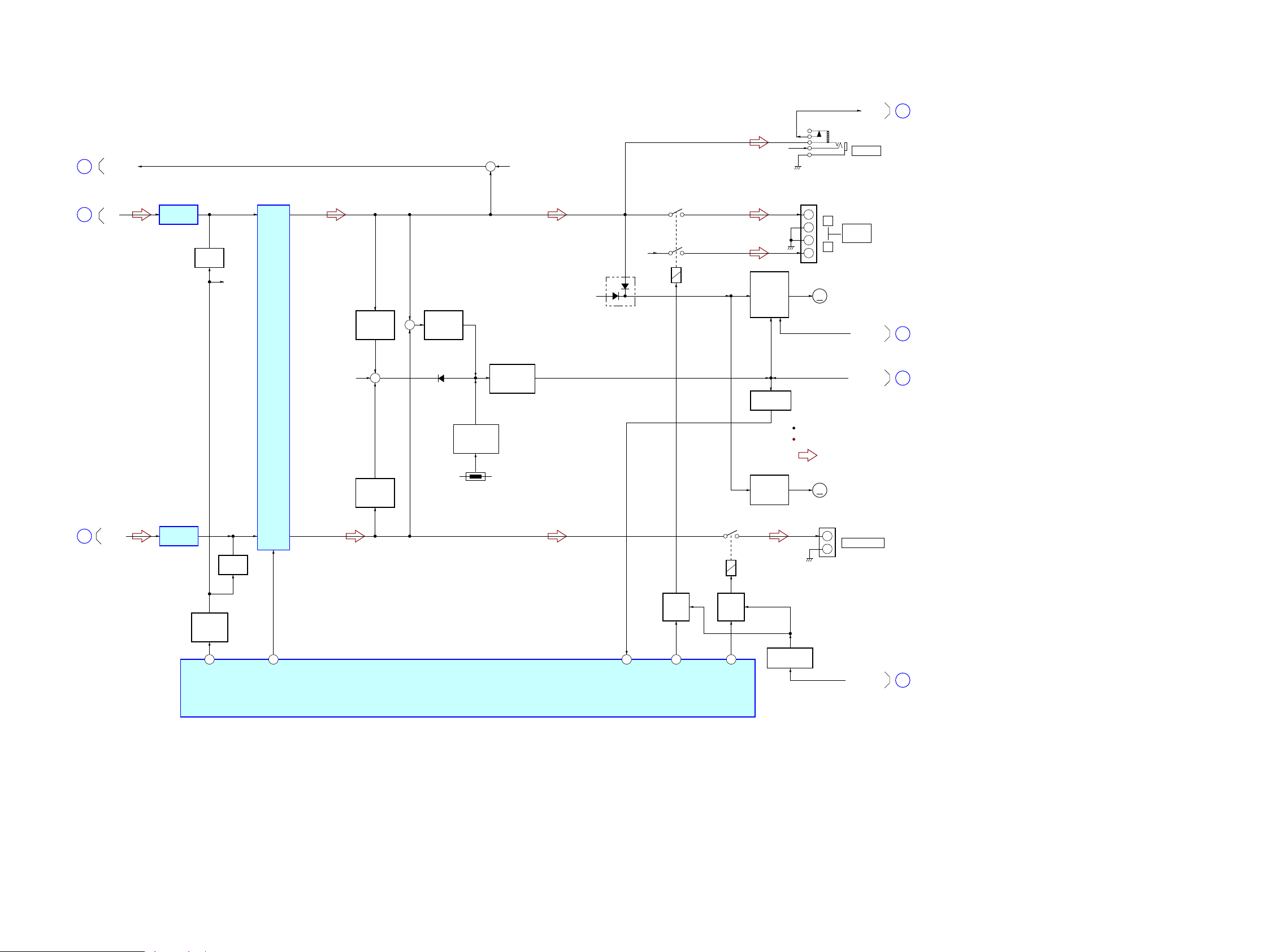
2525
7-3. BLOCK DIAGRAM - AMP Section -
OUT
LINE AMP
IC252
D
BASS AGC
F
SW OUT
E
POWER
AMP
IC800
MUTING
Q402
OVER LOAD
DETECT
Q801
OVER LOAD
DETECT
Q802
R-CH
MUTING
Q430
LINE AMP
IC253
+
R-CH
R-CH
R-CH
MUTING
CONTROL
Q670
LINE MUTE
58
STK MUTE
51
SW SPK RELAY
52
+
R-CH
PROTECT
DETECT
Q806, 809, 811
FAN M OTOR
DRIVE
Q690, 691,
Q693 -695,
Q697
RY800
+
–
–
+
RY890
D632
D807
TH801
M
M102
(FAN)
FAN M OTOR
DRIVE
Q110 - 113
M
M101
(FAN)
PHONES
+
–
SUBWOOFER
JK890
RELAY
DRIVE
Q805
FR SPK RELAY
53
PROTECT
50
RELAY
DRIVE
Q804
R-CH
J702
SYSTEM CONTROLLER
IC401 (3/4)
: TUNER (FM/AM)
SIGNAL PATH
R-ch is omitted due to same as L-ch.
+
OVER LOAD
DETECT
Q803
R
L
FRONT
SPEAKER
JK800
PROTECT
G
DC DETECT
H
STBY LED
J
HP IN
C
DC DETECT
Q815
LEVEL SHIFT
Q447
TEMPERATURE
DETECT
Q807, 808
(Page 24)
(Page 24)
(Page 24)
(Page 24)
(Page 26)
(Page 26)
(Page 26)
HCD-ZT4
HCD-ZT4
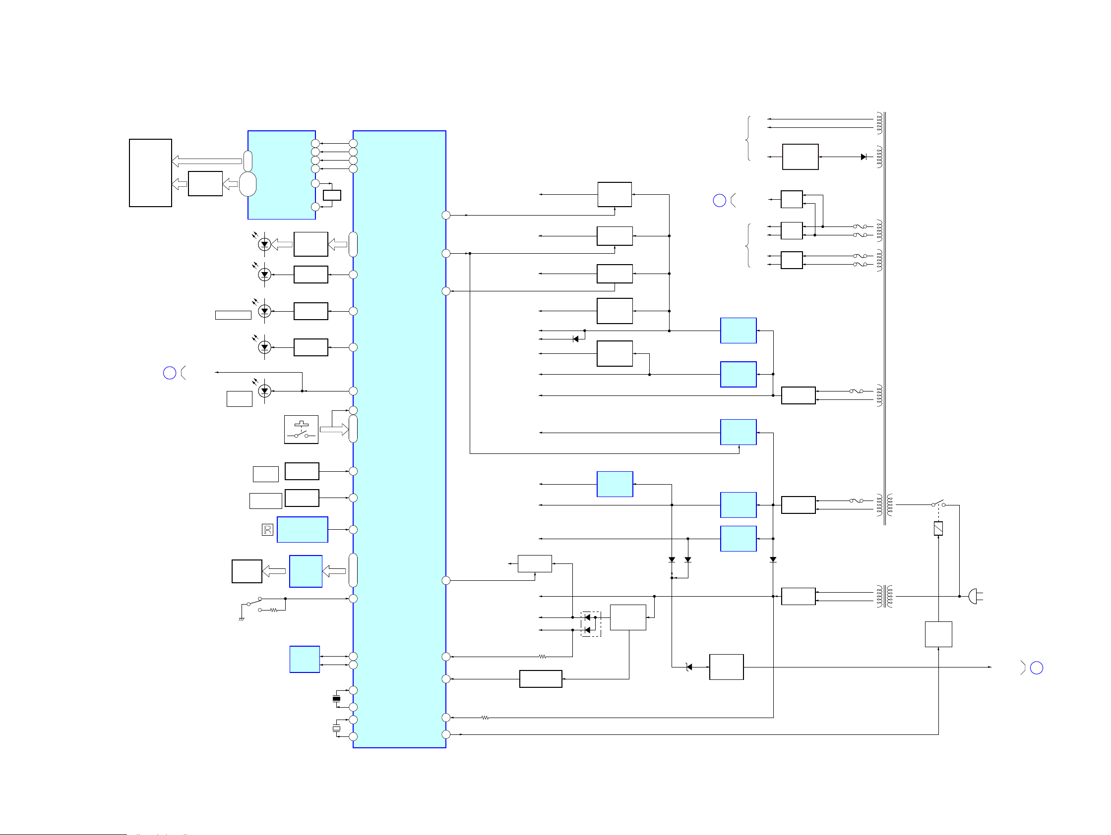
2626
7-4. BLOCK DIAGRAM - PANEL, POWER SUPPLY Section -
REMOTE CONTROL
RECEIVER
IC1102
FL1101
FLUORESCENT
INDICATOR
TUBE
MOTOR
ASSY
S031
(METER POSITION DETECT)
3 SW LED
AD-KEY0 AD-KEY2
FLUORESCENT INDICATOR
TUBE DRIVER
IC1101
SYSTEM CONTROLLER
IC401 (4/4)
F907
RECT
D911, 912
PROTECT
DETECT
Q606
RECT
D602
D006
LED-VOL1. 2 LED-VOL5. 6
S1165 - 1195
54STBY RELAY
20AC-CUT
RESET SWITCH
Q214, 215
D213
+3.3V
UNREG +16V
VBUS+5V
EVER +10V
83OVERVOLTAGE
12RESET
91 MASTER VOL
2 – 13,
15, 16
DR35 - DR16
38 – 19
DR0 - DR13
79 - 77
METER IN1 METER IN4
100, 84, 1, 2 97, 95, 94
LED DRIVE
Q1139, 1141,
Q1143
GRID DRIVE
Q1102 - 1113,
Q111 5, 1116
D1124 - 1129
(STREAM)
LED DRIVE
Q1205
70 USB-BLUE LED
LED DRIVE
Q1190
D1205
SUBWOOFER
72 STBY LED
KEY0
4 SIRCS
D1196
I/
STANDBY
ROTARY
ENCODER
MASTER
VOLUME
OPERATION
DIAL
S1052
90 OPERATION DIAL
ROTARY
ENCODER
S1051
13 X-OUT
15 X-IN
METER SW
X402
5MHz
11 XC-OUT
10 XC-IN
X401
32.768kHz
SI FL-DRIVER-DATA
49 86
SCK FL-DRIVER-CLK
48 85
EEP-SDA
55
EEP-SCL
56
CSB FL-DRIVER-CS
51 87
RSTB FL-DRIVER-RESET
52 88
74 POWER/DISPLAY-KEY
(AC IN)
RY901
RELAY
DRIVE
Q903
D+1.5V
+1.5V
REGULATOR
IC201
DMPORT+5V
D605 D055
D623, 624
D908
A+9V
M+9V
M+7V
F906
RECT
D601
F904
F905
RECT
D801
F908
F909
RECT
D800
RECT
D812
D608
+9V
REGULATOR
IC080
+9V
REGULATOR
IC602
A/D CONVERTER +5V
+5V
REGULATOR
Q696
M+5V
+5V
REGULATOR
Q1220
+3.3V
REGULATOR
IC603
+5V
REGULATOR
IC050
+5V
REGULATOR
IC055
+4V
REGULATOR
Q210 - 212
SEL A, SEL B
CD MECHANISM
MOTOR B+
REGULATOR
Q655 - 658
73LED CTRL
5CDM-SD
TAPE +9V
B+ SWITCH
Q681, 684
49TC_M+9V SW
JOG B+
39AD SUPPLY SW
B+ SWITCH
Q627, 628
–32V
REGULATOR
Q902
AMP
SECTION
B+
FOR
FLUORESCENT
INDICATOR
TUBE
–VFL
VF
VF
PT902
SUB POWER
TRANSFORMER
PT901
MAIN POWER
TRANSFORMER
45
46
XT
XTB
OSC
VDD+3.3V
D+3.3V,
VREF+3.3V
+VH
–VH
+VL
–VL
D1000, 1003
(USB)
80 METER LED
LED DRIVE
Q010
D011 - 015
(ILLUMINATION)
B+ SWITCH
Q1114, 1117,
Q1120, 1122
MOTOR
DRIVE
IC001
EEPROM
IC675
81
PROTECT
G
DC DETECT
H
STBY LED
J
(Page 25)
(Page 25)
(Page 25)
 Loading...