

Sony HCD-XG60,HCD-XG500 Service Manual
SERVICE MANUAL
COMPACT DISC DECK RECEIVER
US Model
Canadian Model
AEP Model
UK Model
HCD-XG500
E Model
HCD-XG60
SPECIFICATIONS
HCD-XG60/XG500
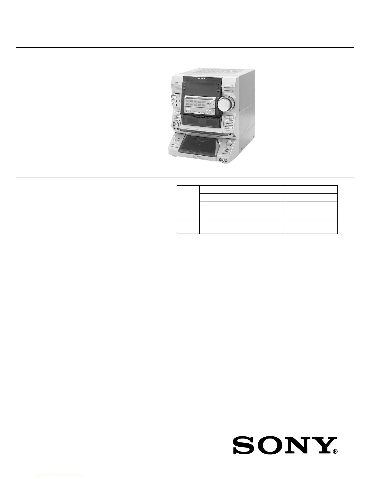
Photo: HCD-XG60
Ver 1.0 2001.02
9-929-577-11 Sony Corporation
2001B0500-1 Audio Entertainment Group
C 2001.2 General Engineering Dept.
HCD-XG60/XG500 is the amplifier, CD
player, tape deck and tuner section in
LBT-XG60/XG500.
Dolby noise reduction manufactured under license
from Dolby Laboratories Licensing Corporation.
“DOLBY” and the double-D symbol ; are trademarks of Dolby Laboratories Licensing Corporation.
Model Name Using Similar Mechanism HCD-LX6/LX50/LX70
CD
CD Mechanism Type CDM37M-5BD32L
Section
Base Unit Name BU-5BD32L
Optical Pick-up Name KSS-213DH
TAPE
Model Name Using Similar Mechanism NEW
Section
T ape Tr ansport Mechanism Type TCM-230PWR42
AUDIO POWER SPECIFICATIONS:
(US model only)
POWER OUTPUT AND TOTAL
HARMONIC DISTORTION
With 6 ohm loads both channels driven, from
120-10,000 Hz; rates 140 watts per channel
minimum RMS power, with no more than 10%
total harmonic distortion.
Amplifier section
Canadian model:
Continuous RMS power output (reference)
160 + 160 watts (6 ohms at
1 kHz, 10% THD)
Total harmonic distortion less than 0.07%
(6 ohms at 1 kHz, 70 W)
AEP, UK models:
DIN power output (rated) 110 + 110 watts
(6 ohms at 1 kHz, DIN)
Continuous RMS power output (reference)
140 + 140 watts
(6 ohms at 1 kHz, 10% THD)
Music power output (reference)
240 + 240 watts
(6 ohms at 1 kHz, 10% THD)
Other models:
The following measured at AC 120/220/240V, 50 Hz
DIN power output (rated) 150 + 150 watts
(6 ohms at 1 kHz, DIN)
Continuous RMS power output (reference)
200 + 200 watts
(6 ohms at 1 kHz, 10% THD)
Inputs
DJ MIX*:
(phono jacks) sensitivity 250 mV,
impedance 47 kilohms
GUITAR IN:
(phone jack) sensitivity 75 mV,
impedance 470 kilohms
PHONO IN:
(phono jacks) sensitivity 3 mV,
impedance 47 kilohms
MIX MIC:
(phone jack) sensitivity 1 mV,
impedance 10 kilohms
VIDEO IN:
(phono jacks) sensitivity 250 mV,
impedance 47 kilohms
GAME IN:
(phono jacks) sensitivity 250 mV,
impedance 47 kilohms
MD IN:
(phono jack) sensitivity 450 mV,
impedance 47 kilohms
Outputs
DJ MIX*:
(phono jacks) sensitivity 250 mV,
impedance 1 kilohms
PHONES:
(stereo phone jack) accepts headphones of 8
ohms or more
VIDEO OUT:
(phono jack) voltage 250 mV
impedance 1 kilohm
MD OUT:
(phono jacks) voltage 250 mV
impedance 1 kilohm
FRONT SPEAKER:
accepts impedance of 6 to
16 ohms
* US, Canadian, AEP, UK, and Mexican models
only
CD player section
System Compact disc and digital
audio system
Laser Semiconductor laser
(λ=780nm), Emission
duration: continuous
Wavelength 780 – 790 nm
Frequency response 2 Hz – 20 kHz (±0.5 dB)
Signal-to-noise ratio More than 90 dB
Dynamic range More than 90 dB
CD OPTICAL DIGITAL OUT
(Square optical connector jack, rear panel)
Wavelength: 660 nm
Output level –18 dBm
– Continued on next page –

13
HCD-XG60/XG500
[CD Delivery Mode]
• This mode moves the optical pick-up to the position durable to
vibration. Use this mode when returning the set to the customer
after repair.
Procedure:
1. Press the ?/1 button to turn the power ON.
2. Press the [LOOP] and ?/1 buttons simultaneously.
3. A message “LOCK” is displayed on the fluorescent indicator
tube, and the CD delivery mode is set.
[LED and Fluorescent Indicator Tube All Lit, Key Check
Mode]
Procedure:
1. Press three buttons of [ /CLOCK SET], [ENTER/NEXT],
and [DISC 2] simultaneously.
2. LEDs and fluorescent indicator tube are all turned on.
Press the [DISC 2] button, and the key check mode is activated.
3. In the key check mode, the fluorescent indicator tube displays
“K 0 J0 V0”. Each time a button is pressed, “K” value increases. However , once a button is pressed, it is no longer taken
into account.
“J” value increases like 1, 2, 3 ... if turn the JOG dial clockwise, or it decreases like 0, 9, 8 ... if turn the JOG dial counterclockwise.
“V” value increases like 1, 2, 3 ... if turn the [VOLUME] dial
clockwise, or it decreases like 0, 9, 8 ... if turn the JOG dial
counterclockwise.
4. To release from this mode, press three buttons in the same
manner as step 1, or disconnect the power cord.
c
[MC Cold Reset]
• The cold reset clears all data including preset data stored in the
RAM to initial conditions. Execute this mode when returning
the set to the customer.
Procedure:
1. Turn the power ON or set to the DEMO mode.
2. Press three buttons of [ /CLOCK SET], [ENTER/NEXT], and
?/1 simultaneously.
3. The set is reset, and displays “COLD RESET”, then becomes
DEMO mode.
[MC Hot Reset]
• This mode resets the set with the preset data kept stored in the
memory. The hot reset mode functions same as if the power
cord is plugged in and out.
Procedure:
1. Turn the power ON or set to the DEMO mode.
2. Press three buttons of [ /CLOCK SET], [ENTER/NEXT],
and [DISC 1] simultaneously.
3. The set is reset, and becomes standby state.
[Change-over the AM Tuning Interval]
(EXCEPT AEP, UK, and Saudi Arabia models)
• The AM tuning interval can be changed over 9 kHz or 10 kHz.
Procedure:
1. Press the ?/1 button to turn the power ON.
2. Select the function “TUNER”, and press the [TUNER/BAND]
button to select the BAND “AM”.
3. Press the ?/1 button to turn the power OFF.
4. Press the [ENTER/NEXT] and ?/1 buttons simultaneously,
and the display on the fluorescent indicator tube changes to
“AM 9 K STEP” or “AM 10 K STEP”, and thus the tuning
interval is changed over.
c
SECTION 4
TEST MODE
c
14
HCD-XG60/XG500
[Aging Mode]
This mode can be used for operation check of tape deck section.
Tape deck section work in parallel.
• If an error occurred:
The aging operation stops and display then status.
• If no error occurs:
The aging operation continues repeatedly.
Procedure:
1. Load the tapes into the decks A and B respectively.
2. Press the [FUNCTION] button to select the function “CD”.
3. Press the [PLAY MODE] b utton to set the “ ALL DISCS” mode,
and press the [REPEAT] button to “REPEAT” off.
4. Press three buttons of [ /CLOCK SET], [ENTER/NEXT],
and [DISC 4] simultaneously.
5. The aging mode is activated, if the indicator of disc tray num-
ber on the fluorescent indicator tube is blinking.
6. To release from the aging mode, press the ?/1 button to turn
the power OFF and operate the cold reset. (Refer to the “MC
Cold Reset”)
1. Display at the Aging Mode
• Display operating state of tape deck section alternately.
• If an error occurred, stop display.
2. Tape Deck Section
• The sequence during the aging mode is following as below.
• If an error occurred, stop display that step.
Aging mode sequence (Tape deck section) :
Rewind the tape A and B
“TAPE A AG-1”
Shut off
FWD play the tape A
“TAPE A AG-2”
2 minutes
Fast forward the tape A
“TAPE A AG-3”
Shut off or 20 seconds
REV play the tape A
“TAPE A AG-4”
2 minutes
Rewind the tape A
“TAPE A AG-5”
Shut off
FWD play the tape B
“TAPE B AG-2”
2 minutes
Fast forward the tape B
“TAPE B AG-3”
Shut off or 20 seconds
REV play the tape B
“TAPE B AG-4”
2 minutes
Rewind the tape B
“TAPE B AG-5”
Shut off
Note: “TAPE * AG-*” is display of each step.
c
HCD-XG60/XG500
2525
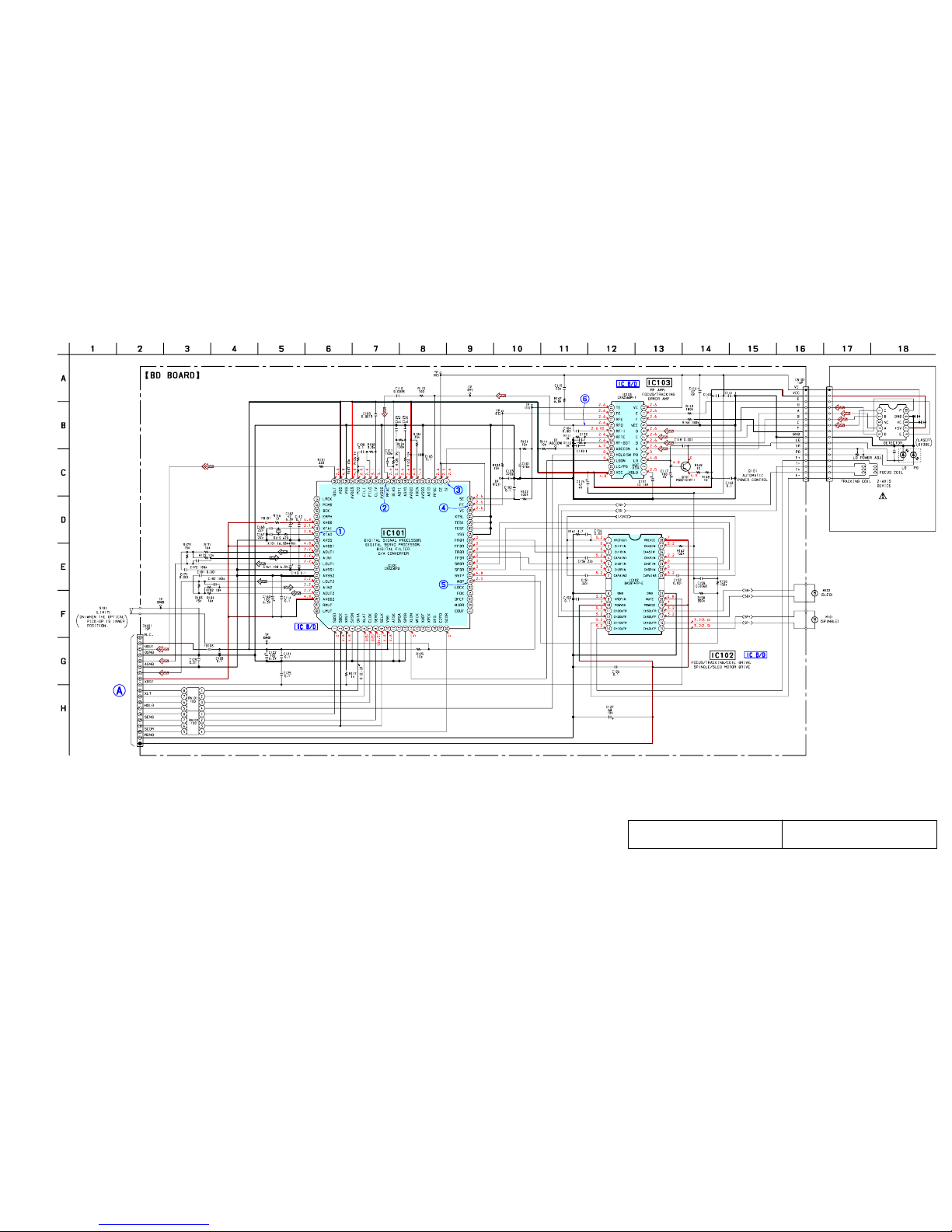
7-7. SCHEMATIC DIAGRAM – BD Board – • See page 35 for Waveforms. • See page 47 for IC Block Diagrams.
MAIN
BOARD
CN411
D+5V (SW)
L-CH
R-CH
A+5V (SW)
CD-DATA
CD-CLK
SQ-DATA
SQ-CLK
M+7V (UNSW)
OPTICAL PICK-UP
BLOCK
(KSS-213DH)
2.2
• Voltages and waveforms are dc with respect to ground
under no-signal conditions.
no mark : CD STOP
( ) : CD PLAY
The components identified by mark 0 or dotted
line with mark 0 are critical for safety.
Replace only with part number specified.
Les composants identifiés par une marque 0 sont
critiques pour la sécurité. Ne les remplacer que
par une pièce portant le numéro spécifié.
(Page 32)
HCD-XG60/XG500
2727
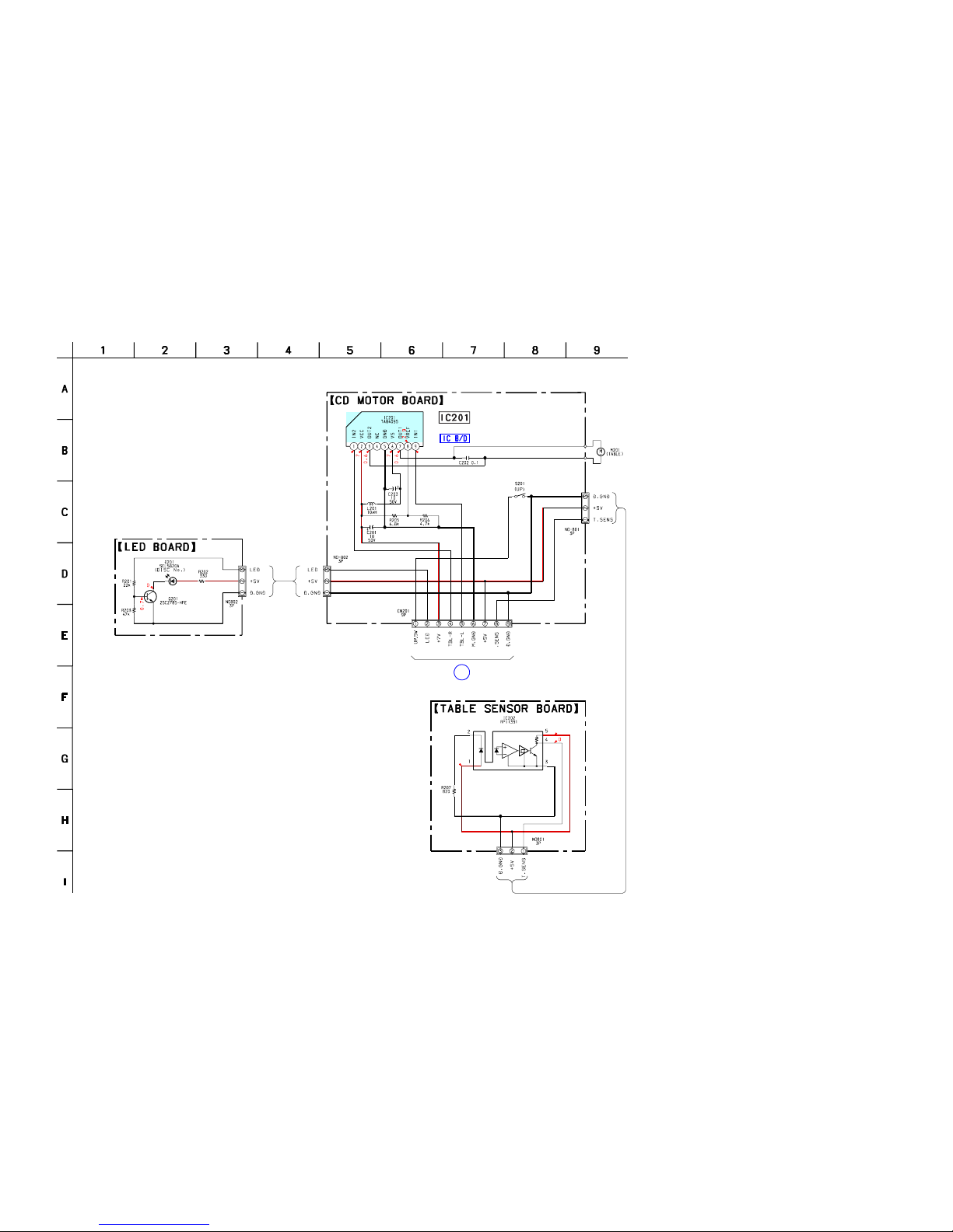
7-9. SCHEMATIC DIAGRAM – CD MOTOR Section –• See page 47 for IC Block Diagram.
B
MAIN BOARD
CN412
4.8
4.8
4.8
4.8
LED DRIVE
TABLE MOTOR DRIVER
DISC TABLE SENSOR
TRAY
• Voltages and waveforms are dc with respect to ground
under no-signal conditions.
no mark : CD STOP
(Page 32)
HCD-XG60/XG500
2929
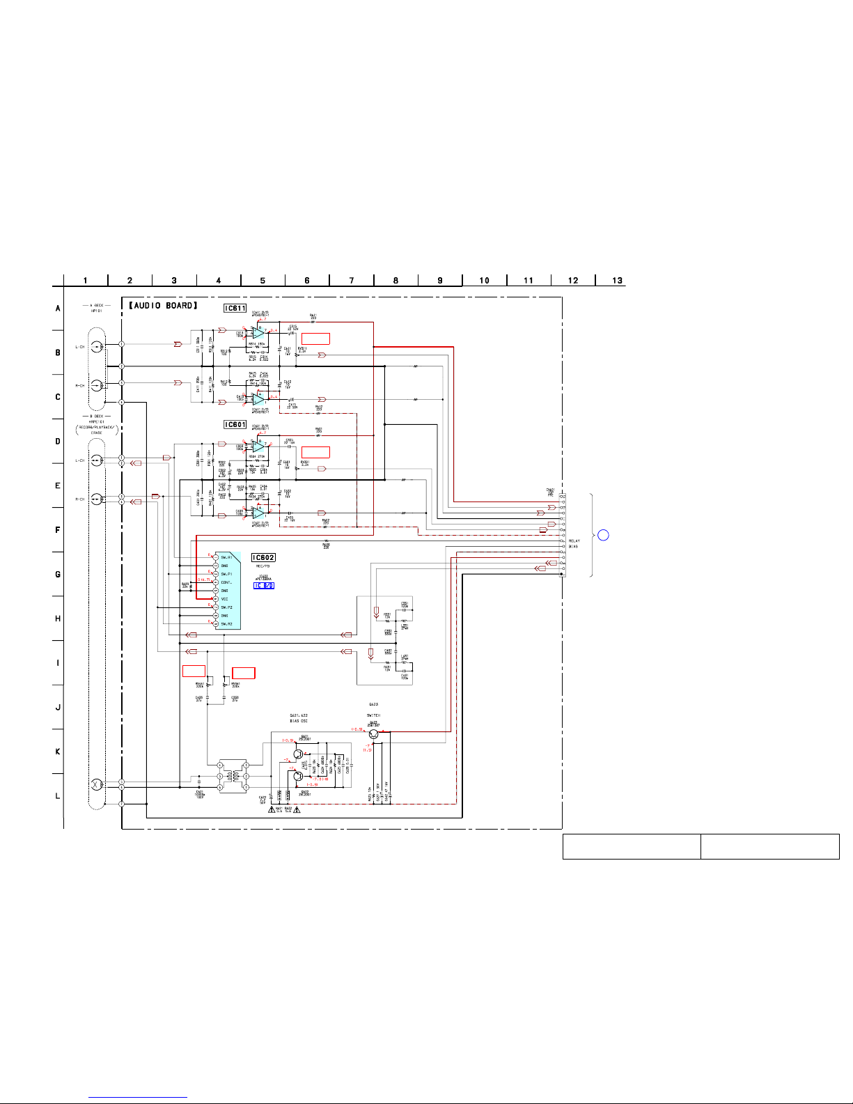
7-11. SCHEMATIC DIAGRAM – AUDIO Board – • See page 47 for IC Block Diagram.
C
MAIN BOARD
CN303
PB LEVEL (L)
(DECK A)
PB LEVEL (L)
(DECK B)
REC BIAS (L)
(DECK B)
REC BIAS (R)
(DECK B)
–7
–7
6.9
6.9–6.5
–6.5
–6.5
–6.5 (–7.2)
(PALYBACK)
PB EQ AMP
(DECK A)
PB EQ AMP
(DECK B)
SWITCHING
T621
BIAS OSC
REC BIAS
NC
A+7.5V
APB-LCH
APB-RCH
AGND
BPB-LCH
BPB-RCH
A–7.5V
–VBIAS (–7.5V)
+VBIAS (+7.5V)
BREC-RCH
BREC-LCH
TC-HEAD-GND
R492 1.5K
R491 820
R482 1.5K
R481 820
• Voltages and waveforms are dc with respect to ground
under no-signal conditions.
no mark : TAPE PLAY
( ) : RECORD
The components identified by mark 0 or dotted
line with mark 0 are critical for safety.
Replace only with part number specified.
Les composants identifiés par une marque 0 sont
critiques pour la sécurité. Ne les remplacer que
par une pièce portant le numéro spécifié.
(Page 32)
 Loading...