

Sony HCD-RG4SR,HCD-RG20,HCD-RG30T Service Manual
HCD-DX10/RG4SR/RG20/RG30T
Q
Q
3
7
6
3
1
5
1
5
0
SERVICE MANUAL
Ver 1.0 2001. 06
TEL 13942296513 QQ 376315150 892498299
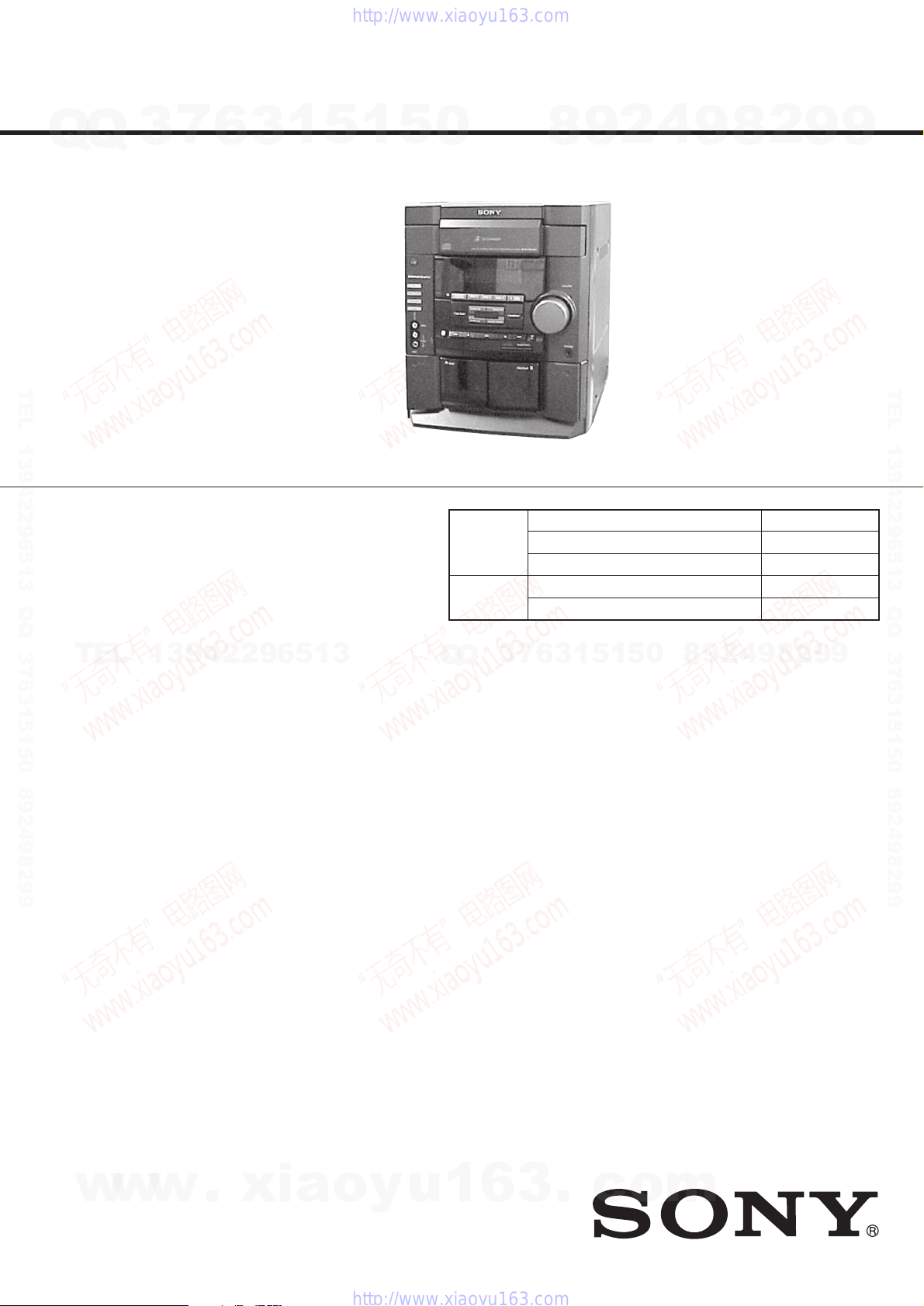
• HCD-DX10/RG4SR/RG20/RG30T is the
tuner, deck, CD and amplifier section in
MHC-DX10/RG4SR/RG20/RG30T.
Photo : HCD-DX10
CD
Section
Tape deck Model Name Using Similar Mechanism NEW
Section T ape Transport Mechanism T ype CWL44FF29
8
9
2
4
9
8
2
9
US Model
HCD-RG4SR/RG20/RG30T
Canadian Model
HCD-RG20/RG30T
AEP Model
UK Model
HCD-RG20
E Model
Australian Model
HCD-DX10
Model Name Using Similar Mechanism NEW
CD Mechanism Type CDM58F-K6
Optical Pick-up Name
KSM-213DCP/Z-NP
9
TEL 13942296513 QQ 376315150 892498299
TEL
13942296513
AUDIO POWER SPECIFICATIONS:
(HCD-RG4SR USA model only)
POWER OUTPUT AND TOTAL
HARMONIC DISTORTION:
with 6 ohm loads both channels driven, from
120 – 10,000 Hz; rates 100 watts per channel
minimum RMS power, with no more than 10%
total harmonic distortion from 250 milliwatts to
rated output.
Total harmonic distortion less than 0.07%
(HCD-RG30T USA model only)
POWER OUTPUT AND TOTAL
HARMONIC DISTORTION:
with 6 ohm loads both channels driven, from
120 – 10,000 Hz; rates 75 watts per channel
minimum RMS power, with no more than 10%
total harmonic distortion from 250 milliwatts to
rated output.
Total harmonic distortion less than 0.07%
(HCD-RG20 USA model only)
POWER OUTPUT AND TOTAL
HARMONIC DISTORTION:
with 6 ohm loads both channels driven, from
120 – 10,000 Hz; rates 60 watts per channel
minimum RMS power, with no more than 10%
total harmonic distortion from 250 milliwatts to
rated output.
Total harmonic distortion less than 0.07%
(6 ohms at 1 kHz, 50 W)
(6 ohms at 1 kHz, 30 W)
(6 ohms at 1 kHz, 30 W)
SPECIFICATIONS
Q
Amplifier section
Canadian models:
HCD-RG30T
Continuous RMS power output (reference)
Total harmonic distortion less than 0.07%
HCD-RG20
Continuous RMS power output (reference)
Total harmonic distortion less than 0.07%
European model:
HCD-RG20
DIN power output (rated) 40 + 40 watts
Continuous RMS power output (reference)
Music power output (reference)
Other model:
HCD-DX10
The following measured at AC 120, 220, 240 V
50/60 Hz
DIN power output (rated) 40 + 40 watts
Continuous RMS power output (reference)
3
Q
75 + 75 watts (6 ohms at 1
kHz, 10% THD)
(6 ohms at 1 kHz, 50 W)
60 + 60 watts (6 ohms at 1
kHz, 10% THD)
(6 ohms at 1 kHz, 30 W)
(6 ohms at 1 kHz, DIN)
50 + 50 watts (6 ohms at 1
kHz, 10% THD)
95 + 95 watts (6 ohms
at 1 kHz, 10% THD)
(6 ohms at 1 kHz, DIN)
50 + 50 watts (6 ohms at 1
kHz, 10% THD)
7
6
3
MINI HIFI COMPONENT SYSTEM
1
9
4
2
9
8
0
5
1
5
Inputs
GAME (AUDIO) IN (phono jack):
Outputs
PHONES (stereo mini jack):
Front speaker: accepts impedance of 6 to
Surround speaker (HCD-RG4SR only):
CD player section
System Compact disc and digital
Laser Semiconductor laser
Frequency response 2 Hz – 20 kHz (±0.5 dB)
Wavelength 780 – 790 nm
Signal-to-noise ratio More than 90 dB
Dynamic range More than 90 dB
Tape deck section
Recording system 4-track 2-channel stereo
Frequency response 40 – 13,000 Hz (±3 dB),
voltage 450 mV,
impedance 47 kilohms
accepts headphones of
8 ohms or more
16 ohms
accepts impedance of 6 to
16 ohms
audio system
(λ=780 nm)
Emission duration:
continuous
using Sony TYPE I
cassette
— Continued on next page —
8
2
9
9
w
w
9-873-225-01
2001F1600-1
© 2001.6
w
.
xia
Sony Corporation
Home Audio Company
Shinagawa Tec Service Manual Production Group
o
y
u
1
6
3
.
c
o
m
HCD-DX10/RG4SR/RG20/RG30T
Tuner section
FM stereo, FM/AM superheterodyne tuner
Q
Q
FM tuner section
Tuning range 87.5 – 108.0 MHz
Antenna FM lead antenna
Antenna terminals 75 ohm unbalanced
Intermediate frequency 10.7 MHz
AM tuner section
Tuning range
Pan-American models: 530 – 1,710 kHz (with the
European and Middle Eastern models:
Other models: 531 – 1,602 kHz (with the
TEL 13942296513 QQ 376315150 892498299
Antenna AM loop antenna
Antenna terminals External antenna terminal
Intermediate frequency 450 kHz
General
Power requirements
North American models: 120 V AC, 60 Hz
European models: 230 V AC, 50/60 Hz
Australian models: 230 – 240 V AC,
Mexican models: 120 V AC, 50/60 Hz
Other models: 120 V, 220 V or
Power consumption
USA models:
HCD-RG4SR: 160 watts
HCD-RG30T: 115 watts
HCD-RG20: 95 watts
Canadian models:
TEL
HCD-RG30T: 115 watts
HCD-RG20: 95 watts
European model:
HCD-RG20: 85 watts
Other model:
HCD-DX10: 85 watts
Dimensions (w/h/d)
Mass
North American models:
HCD-RG4SR: Approx. 8.7 kg
HCD-RG30T: Approx. 8.2 kg
HCD-RG20: Approx. 7.8 kg
European model:
HCD-RG20: Approx. 8.1 kg
Other model:
HCD-DX10: Approx. 8.2 kg
Design and specifications are subject to change
without notice.
7
3
interval set at 10 kHz)
531 – 1,710 kHz (with the
interval set at 9 kHz)
531 – 1,602 kHz (with the
interval set at 9 kHz)
interval set at 9 kHz)
530 – 1,710 kHz (with the
interval set at 10 kHz)
50/60 Hz
230 – 240 V AC,
50/60 Hz
Adjustable with voltage
selector
6
3
1
13942296513
1.0 watts (at the Power
Saving Mode)
Approx. 280 × 325 × 421 mm
5
1
5
0
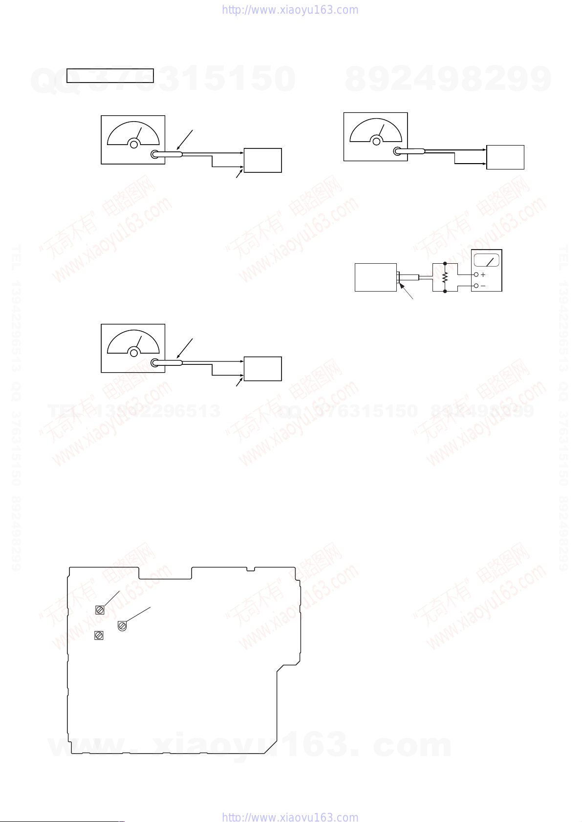
After correcting the original service problem, perform the
following safety checks before releasing the set to the customer:
Check the antenna terminals, metal trim, “metallized” knobs, screws,
and all other exposed metal parts for A C leakage. Check leakage as
described below.
LEAKAGE
The A C leakag e from any exposed metal part to earth g round and
from all exposed metal parts to any exposed metal part having a
return to chassis, must not exceed 0.5 mA (500 microamperes).
Leakage current can be measured by any one of three methods.
1. A commercial leakage tester, such as the Simpson 229 or RCA
WT -540A. Follo w the manufacturers’ instructions to use these
instruments.
2. A battery-operated AC milliammeter. The Data Precision 245
digital multimeter is suitable for this job.
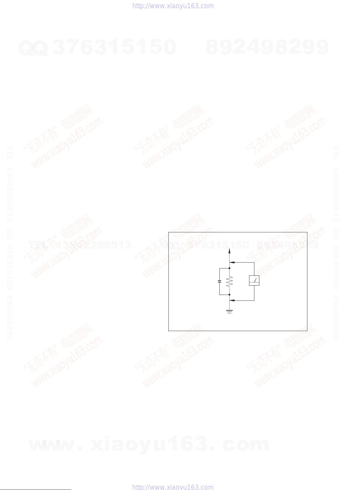
3. Measuring the voltage drop across a resistor by means of a
VOM or battery-operated A C voltmeter . The “limit” indication
is 0.75 V, so analog meters must have an accurate low-voltage
scale. The Simpson 250 and Sanwa SH-63Trd are e xamples of
a passive VOM that is suitable. Nearly all battery operated
digital multimeters that have a 2V AC range are suitable. (See
Fig. A)
Q
Q
SAFETY CHECK-OUT
7
3
Fig. A. Using an A C v oltmeter to check A C leakage.
9
8
T o Exposed Metal
Parts on Set
1
3
6
0.15 µF
5
1
4
2
0
5
1.5 kΩ
Earth Ground
9
9
8
AC
Voltmeter
(0.75 V)
8
2
4
2
9
8
9
2
9
9
TEL 13942296513 QQ 376315150 892498299
9
SAFETY-RELATED COMPONENT WARNING!!
COMPONENTS IDENTIFIED BY MARK 0 OR DOTTED LINE WITH
MARK 0 ON THE SCHEMATIC DIAGRAMS AND IN THE PARTS
LIST ARE CRITICAL TO SAFE OPERATION. REPLACE THESE
COMPONENTS WITH SONY PARTS WHOSE PART NUMBERS
w
w
APPEAR AS SHOWN IN THIS MANUAL OR IN SUPPLEMENTS
PUBLISHED BY SONY.
2
w
.
xia
o
y
ATTENTION AU COMPOSANT AYANT RAPPORT
LES COMPOSANTS IDENTIFÉS P AR UNE MARQUE 0 SUR LES
DIAGRAMMES SCHÉMA TIQUES ET LA LISTE DES PIÈCES SONT
CRITIQUES POUR LA SÉCURITÉ DE FONCTIONNEMENT. NE
REMPLACER CES COMPOSANTS QUE PAR DES PIÈSES SONY
u
1
6
DONT LES NUMÉROS SONT DONNÉS DANS CE MANUEL OU
DANS LES SUPPÉMENTS PUBLIÉS PAR SONY.
3
À LA SÉCURITÉ!
.
c
o
m
HCD-DX10/RG4SR/RG20/RG30T
NOTES ON HANDLING THE OPTICAL PICK-UP
Q
TEL 13942296513 QQ 376315150 892498299
BLOCK OR BASE UNIT
Q
The laser diode in the optical pick-up block may suffer electrostatic
break-down because of the potential difference generated by the
charged electrostatic load, etc. on clothing and the human body.
During repair, pay attention to electrostatic break-down and also
use the procedure in the printed matter which is included in the
repair parts.
The flexible board is easily damaged and should be handled with
care.
NOTES ON LASER DIODE EMISSION CHECK
The laser beam on this model is concentrated so as to be focused on
the disc reflective surface by the objective lens in the optical pickup block. Therefore, when checking the laser diode emission,
observe from more than 30 cm away from the objective lens.
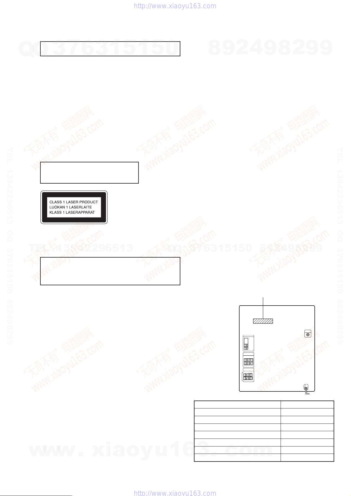
Laser component in this product is capable
of emitting radiation exceeding the limit for
Class 1.
This appliance is classified as a CLASS 1 LASER product. The
CLASS 1 LASER PRODUCT MARKING is located on the rear
exterior.
TEL
CAUTION
Use of controls or adjustments or performance of procedures
other than those specified herein may result in hazardous radiation
exposure.
Notes on chip component replacement
• Never reuse a disconnected chip component.
• Notice that the minus side of a tantalum capacitor may be
damaged by heat.
3
7
6
3
1
13942296513
5
1
5
0
Q
Q
1. GENERAL ·········································································· 4
2. DISASSEMBLY ································································ 6
3. TEST MODE ···································································· 11
4. ELECTRICAL ADJUSTMENTS ······························· 13
5. DIAGRAMS······································································ 15
5-1. Circuit Board Location ················································ 15
5-2. Block Diagrams ··························································· 16
5-3. Printed Wiring Board CD Section ····························· 18
5-4. Schematic Diagram CD Section ································ 19
5-5. Printed Wiring Board Main Section ·························· 20
5-6. Schematic Diagram Main Section (1/4) ···················· 21
5-7. Schematic Diagram Main Section (2/4) ···················· 22
5-8. Schematic Diagram Main Section (3/4) ···················· 23
5-9. Schematic Diagram Main Section (4/4) ···················· 24
5-10.Printed Wiring Board Address Sensor,
5-11.Printed Wiring Board Panel Section·························· 26
5-12.Schematic Diagram Panel Section ···························· 27
5-13.Printed Wiring Board Power Section ························ 28
5-14.Printed Wiring Board Trans Section ·························· 29
5-15.Schematic Diagram Trans Section ···························· 30
5-16.IC Block Diagrams ······················································ 31
5-17.IC Pin Function Description ········································ 34
6. EXPLODED VIEWS
6-1. Main Section ······························································· 36
6-2. Front Panel Section ····················································· 37
7
3
6-3. Main Board Section ····················································· 38
6-4. CD Mechanism Deck Section ····································· 39
7. ELECTRICAL PARTS LIST ······································· 40
MODEL IDENTIFICATION
— BACK PANEL —
TABLE OF CONTENTS
4
2
9
8
Tuner/CD Section························································ 16
Main Section ······························································· 17
Driver Motor Section··················································· 25
0
5
1
5
1
3
6
9
9
8
PARTS No.
2
8
4
2
9
8
9
2
9
9
TEL 13942296513 QQ 376315150 892498299
9
Flexible Circuit Board Repairing
• Keep the temperature of soldering iron around 270˚C
during repairing.
• Do not touch the soldering iron on the same conductor of the
circuit board (within 3 times).
• Be careful not to apply force on the conductor when soldering
or unsoldering.
• Abbreviation
CND : Canadian model
AUS : Australian model
AR : Argentina model
SP : Singapore model
TW : Taiwan model
MX : Mexican model
MY : Malaysia model
E2 : 120V AC Area in E model
w
w
w
.
xia
E3 : 240V AC Area in E model
o
E51 : Chilean and Peruvian model
y
u
1
RG20: US, CND models
RG20: AEP, UK models
DX10: E2, E3, E51, TW models
DX10: AUS, AR, MX models
RG30T
RG4SR
6
3
.
DX10: MY, SP models
c
MODEL
o
m
PARTS No.
4-234-701-0s
4-234-701-1s
4-234-701-2s
4-234-701-3s
4-234-701-4s
4-234-701-5s
4-234-701-6s
3
HCD-DX10/RG4SR/RG20/RG30T
Q
Q
7
3
Main unit
6
3
1
5
SECTION 1
GENERAL
1
5
0
8
9
This section is extracted
4
2
from instruction manual.
9
8
2
9
9
12
TEL 13942296513 QQ 376315150 892498299
TEL
13942296513
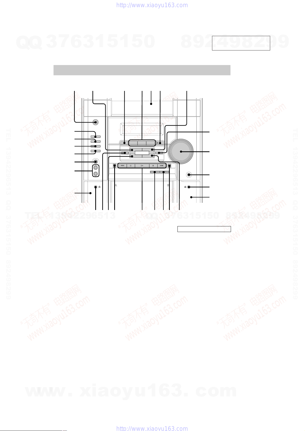
wk
wj
wh
wg
wf
wd
ws
AUDIO jacks wd (19)
CD wk (10 – 12, 15)
CD SYNC qh (15)
Deck A ws (14)
Deck B qs (14 – 16)
DISC 1 – 3 4 (10, 11)
DISC SKIP EX-CHANGE 3
(10, 11)
Disc tray 5 (10)
DISPLAY w; (12)
EFFECT ON/OFF qd
(17)
GAME wg (18 – 20)
3456 7
7
3
Q
Q
GAME EQ ql (17, 18, 20)
GROOVE 8 (17)
MOVIE EQ 7 (17)
MUSIC EQ 2 (17)
PHONES jack q;
REC PAUSE/START qg (15)
TAPE A/B wh (14, 15)
TUNER/BAND wj (12, 13, 15)
VIDEO jack wf (19, 20)
VOLUME control 9
8
9
q;
qa
qs
qdqfqgqhqjqkqlw;wa
6
BUTTON DESCRIPTIONS
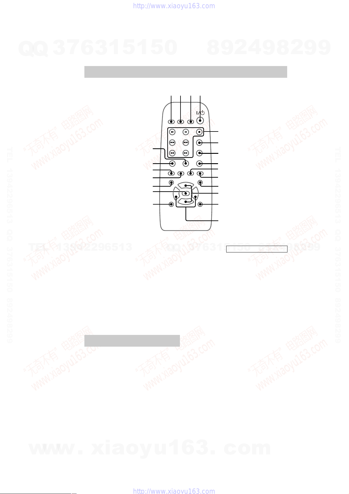
?/1 (power) 1
Z OPEN/CLOSE 6
Z (deck B) qa
M (fast forward) qf
. (go back) qj
> (go forward) qj
X (pause) qj
H (play) qj
x (stop) qj
m (rewind) qk
Z (deck A) wa
3
1
5
1
5
0
8
9
2
4
9
8
2
9
TEL 13942296513 QQ 376315150 892498299
9
4
w
w
w
.
xia
o
y
u
1
6
3
.
c
o
m
HCD-DX10/RG4SR/RG20/RG30T
7
Q
Q
TEL 13942296513 QQ 376315150 892498299
3
6
Remote Control
3
1
5
1
wa
w;
ql
qk
qj
qh
qg
5
0
12 3 4
8
9
5
6
7
8
9
0
qa
qs
qd
qf
2
4
9
8
2
9
9
TEL 13942296513 QQ 376315150 892498299
TEL
13942296513
CD ql (10 – 12, 15)
CLEAR w; (11)
CLOCK/TIMER SELECT 2
(16, 19)
CLOCK/TIMER SET 3 (9, 16,
18)
DISPLAY 6 (12)
D.SKIP 7 (10)
ENTER qg (9, 11 – 13, 16, 18,
19)
EQ +/– qf (17)
GAME q; (18 – 20)
GROOVE qd (17)
Setting the time
1
Press ?/1 to turn on the system.
2
Press CLOCK/TIMER SET on the
remote.
Proceed to step 5 when “CLOCK” appears
in the display.
3
Press . or > repeatedly to select
“SET CLOCK”.
4
Press ENTER on the remote.
5
Press . or > repeatedly to set the
hour.
ON/OFF qh (17)
Q
Q
PLAY MODE wa (10, 11)
PRESET +/– 5 (13)
REPEAT 8 (11)
SLEEP 1 (18)
STEREO/MONO 8 (13)
SURROUND qa (17)
TAPE A/B 9 (14, 15)
TUNER MEMORY qj (12, 13)
TUNER/BAND qk (12, 13)
TUNING +/– 5 (12, 13)
VOL +/– qs
6
7
3
6
Press ENTER on the remote.
The minute indication flashes.
7
Press . or > repeatedly to set the
minute.
8
Press ENTER on the remote.
Tip
If you made a mistake or want to change the time,
start over from step 2.
Note
The clock settings are canceled when you disconnect
the power cord or if a power failure occurs.
5
1
3
?/1 (power) 4
M (fast forward) 5
. (go back) 5
> (go forward) 5
X (pause) 5
N (play) 5
m (rewind) 5
x (stop) 5
4
2
9
8
0
5
1
BUTTON DESCRIPTIONS
9
8
2
9
9
w
w
w
.
xia
o
y
u
1
6
3
.
c
o
m
5
HCD-DX10/RG4SR/RG20/RG30T
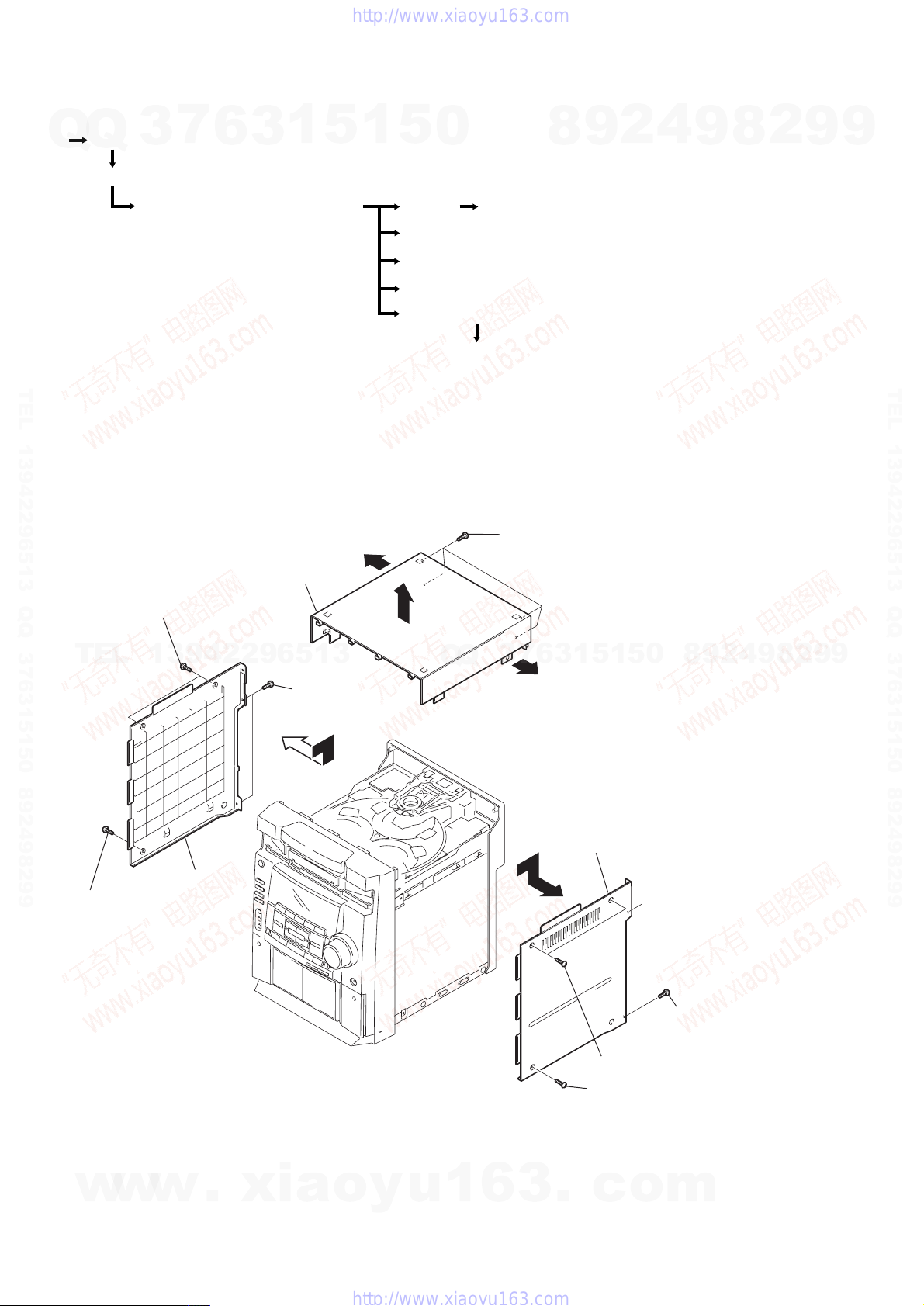
Note : Disassemble the unit in the order as shown below.
Set
Q
Case (Top)
Q
CD door
3
7
6
3
1
5
SECTION 2
DISASSEMBLY
1
5
0
8
9
2
4
9
8
2
9
9
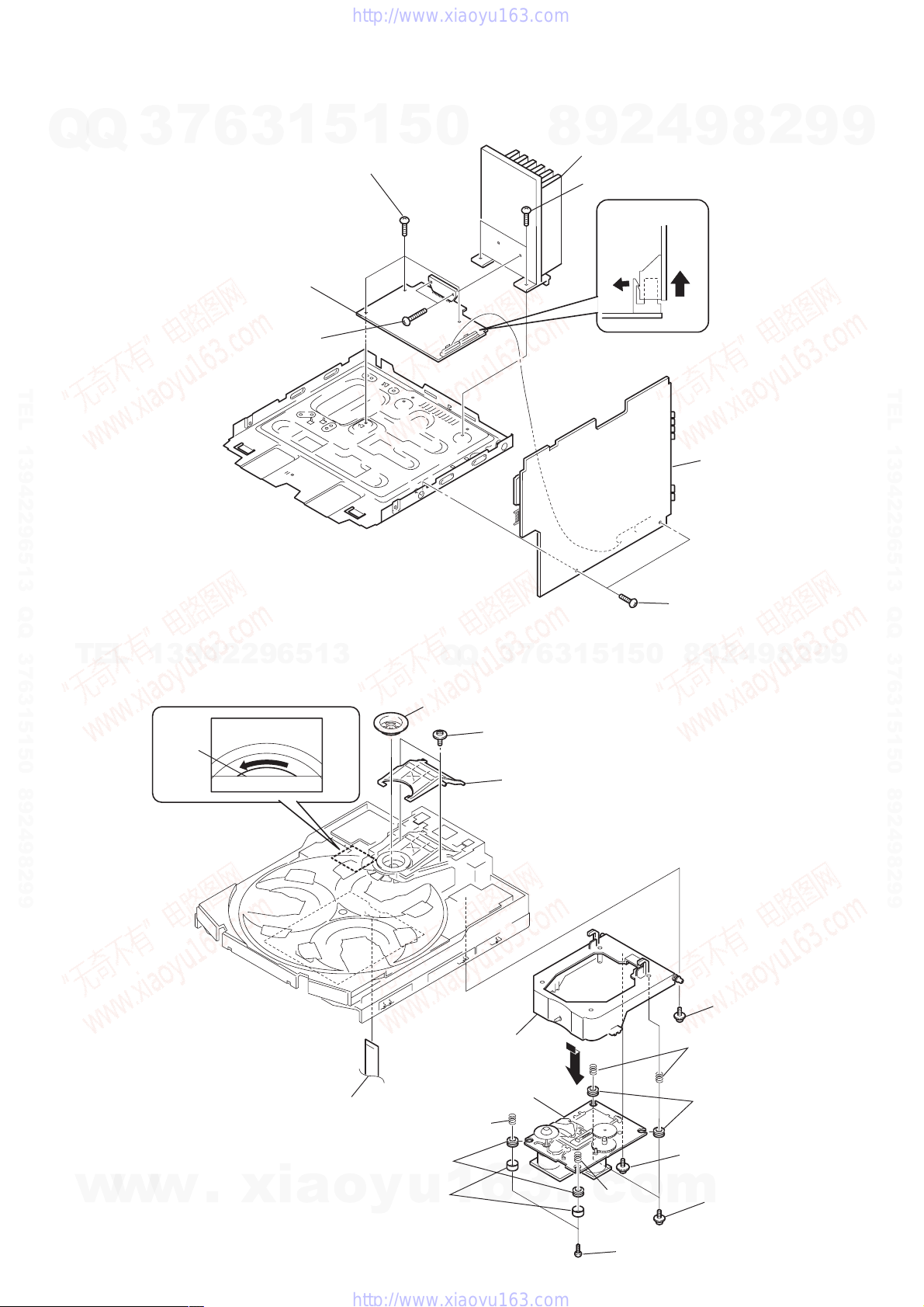
Front panel section and CD mechanism
deck (CDM58F-K6) section
TEL 13942296513 QQ 376315150 892498299
Note : Follow the disassembly procedure in the numerical order given.
2-1. CASE (TOP)
q;
Case (Top)
5
Two screws (Case 3 TP2)
Base unit
Panel board
Tape mechanism deck and Panel board
CD board
Sub trans board, Video out board and Trans board
Main board and Power board
qa
CD board, Driver board, Motor board and Address sensor board
9
Four screws (+BVTP 3
×
TEL 13942296513 QQ 376315150 892498299
6)
TEL
6
Screw (Case 3 TP2)
13942296513
Case (Side-L)
7
Two screws
(+BVTP 3
8
×
10)
Q
Q
3
7
6
3
q;
4
0
5
1
5
1
Case (Side-R)
1
Two screws (Case 3 TP2)
2
Screw (Case 3 TP2)
2
9
8
3
Two
screws
(+BVTP 3
4
×
9
10)
8
2
9
9
6
w
w
w
.
xia
o
y
u
1
6
3
.
c
o
m
Q
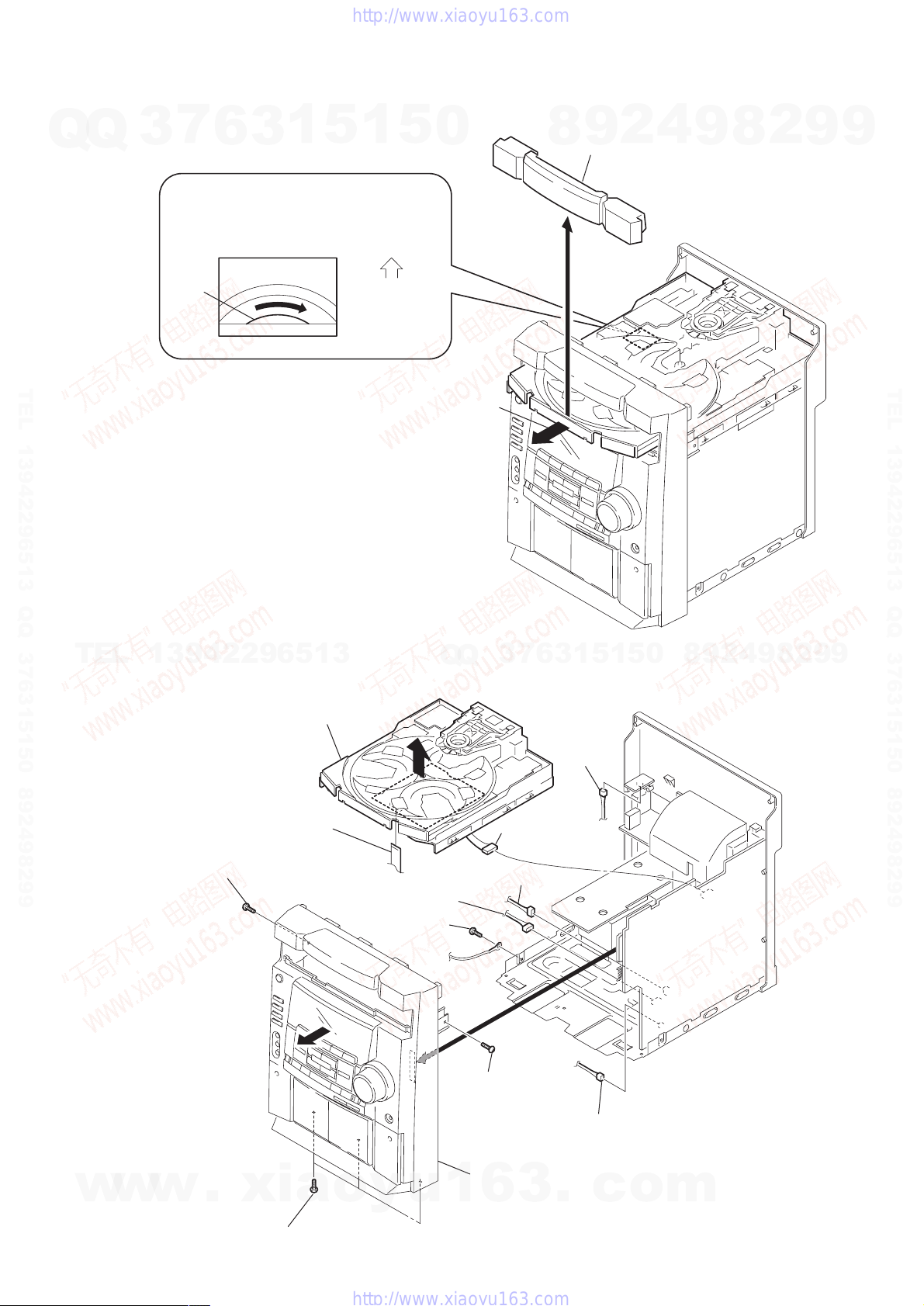
2-2. CD DOOR
Q
3
7
6
CD mechanism deck (CDM58F-K6)
1
Turn the pulley to the direction of arrow.
3
1
5
1
Front panel side
5
0
HCD-DX10/RG4SR/RG20/RG30T
8
CD door
9
2
4
9
8
2
9
9
pulley
TEL 13942296513 QQ 376315150 892498299
2
Pull-out the disc tray.
2-3. FRONT PANEL SECTION AND CD MECHANISM DECK (CDM58F-K6) SECTION
TEL
13942296513
CD mechanism deck
(CDM58F-K6)
5
Q
Q
3
7
3
1
3
6
q;
Connector
(CN605)
5
1
5
0
8
9
2
4
9
8
2
9
TEL 13942296513 QQ 376315150 892498299
9
w
w
w
2
Flat type wire (19 core)
4
Screw (+BVTP 3
.
xia
qa
Three screws (+BVTP 3
×
qd
10)
7
Connector (CN202)
9
Screw
(+BVTP 3
qs
o
y
× 10
×
10)
u
)
1
(CN704)
6
Connector (CN201)
3
Screw
(+BVTP 3
Front panel section
1
6
Connector
×
10)
3
.
8
Connector (CN203)
c
o
m
7
)
HCD-DX10/RG4SR/RG20/RG30T
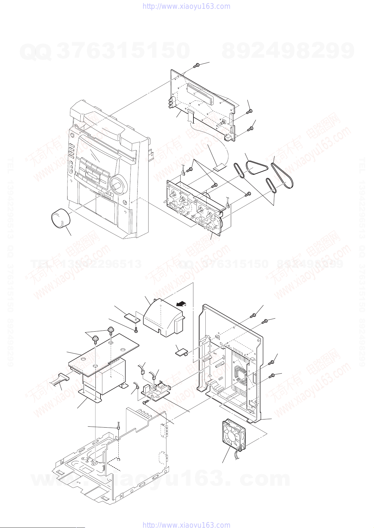
2-4. TAPE MECHANISM DECK AND PANEL BOARD
7
Q
Q
TEL 13942296513 QQ 376315150 892498299
3
6
3
1
5
1
5
qa
PANEL board
1
Flat type wire (17 core)
2
Six screws
(+BVTP 2.6
0
8
(+BVTP 2.6
×
8)
9
8
Six screws
4
2
×
8)
9
Five screws
(+BVTP 2.6
q;
(+BVTP 2.6
Belt (BF)
4
9
×
8)
Eight screws
5
Belt (AF)
×
8
8)
2
9
9
TEL 13942296513 QQ 376315150 892498299
7
Volume knob
TEL
2-5. SUB TRANS BOARD, VIDEO OUT BOARD AND TRANS BOARD
TRANS board
13942296513
8
SENSOR board
7
Screw (+BVTP 3
qk
Four screws
(+BVTT 4
×
×
10)
6)
Cover (duct)
qs
VIDEO OUT board
1
Connector (CN901)
2
3
Tape mechanism deck
Q
Q
6
Connector (CN2)
3
7
6
3
1
5
1
5
6
Belt (FR
8
0
qa
Screw
(+BVTP 3
5
(+BVTP 3
qd
(+BVTP 3
9
4
2
9
×
10)
Two screws
Five screws
qg
(+BVTP 3
×
×
Two screws
10)
10)
×
8
10)
2
9
9
qj
Connector (CN915)
ql
Power
4
w
8
transformer (T911)
Connector (CN504)
w
w
.
3
Connector
(CN903)
xia
q;
SUB TRANS
board
9
Two screws
(+BVTP 3
o
y
u
1
×
qh
6
10)
3
D
C fan (M961)
.
c
o
qf
Back panel
m
s
Q
2-6. MAIN BOARD AND POWER BOARD
Q
3
7
6
3
1
5
6
Three screws (+BVTP 3
1
5
0
×
8)
8
HCD-DX10/RG4SR/RG20/RG30T
4
2
9
9
Heat sink
8
Two screws (+BVTP 3
MAIN board
9
8
× 8)
2
9
9
7
POWER
5
Two screws (+BVTP 3
TEL 13942296513 QQ 376315150 892498299
2-7. BASE UNIT
TEL
13942296513
4
Turn the pulley to the direction of arrow.
board
×
16)
3
Q
Q
1
Pulley (B), chucking
7
6
3
1
5
2
1
5
3
4
1
Two screws (+BVTP 3
9
8
0
MAIN board
9
4
2
8
2
×
9
TEL 13942296513 QQ 376315150 892498299
10)
9
pulley
5
Flat type wire (16 core)
Spring (insulator),
coil
qd
Two insulators
2
7
Holder (BU) assy
Base unit
Two
screws (+PTPWH M2.6)
3
Lever (lifter)
qs
6
Screw
(+PTPWH M2.6)
Two spring (insulator), coil
qd
Two insulators
qa
Screw (DIA. 12)
w
w
w
.
xia
9
Two stoppers (BU)
o
y
u
1
6
3
.
Spring
c
o
(insulator),
coil
m
8
Two screws (+BVTP 2.6
q;
Two
screws
(+PTPWH M2.6)
×
8)
9
HCD-DX10/RG4SR/RG20/RG30T
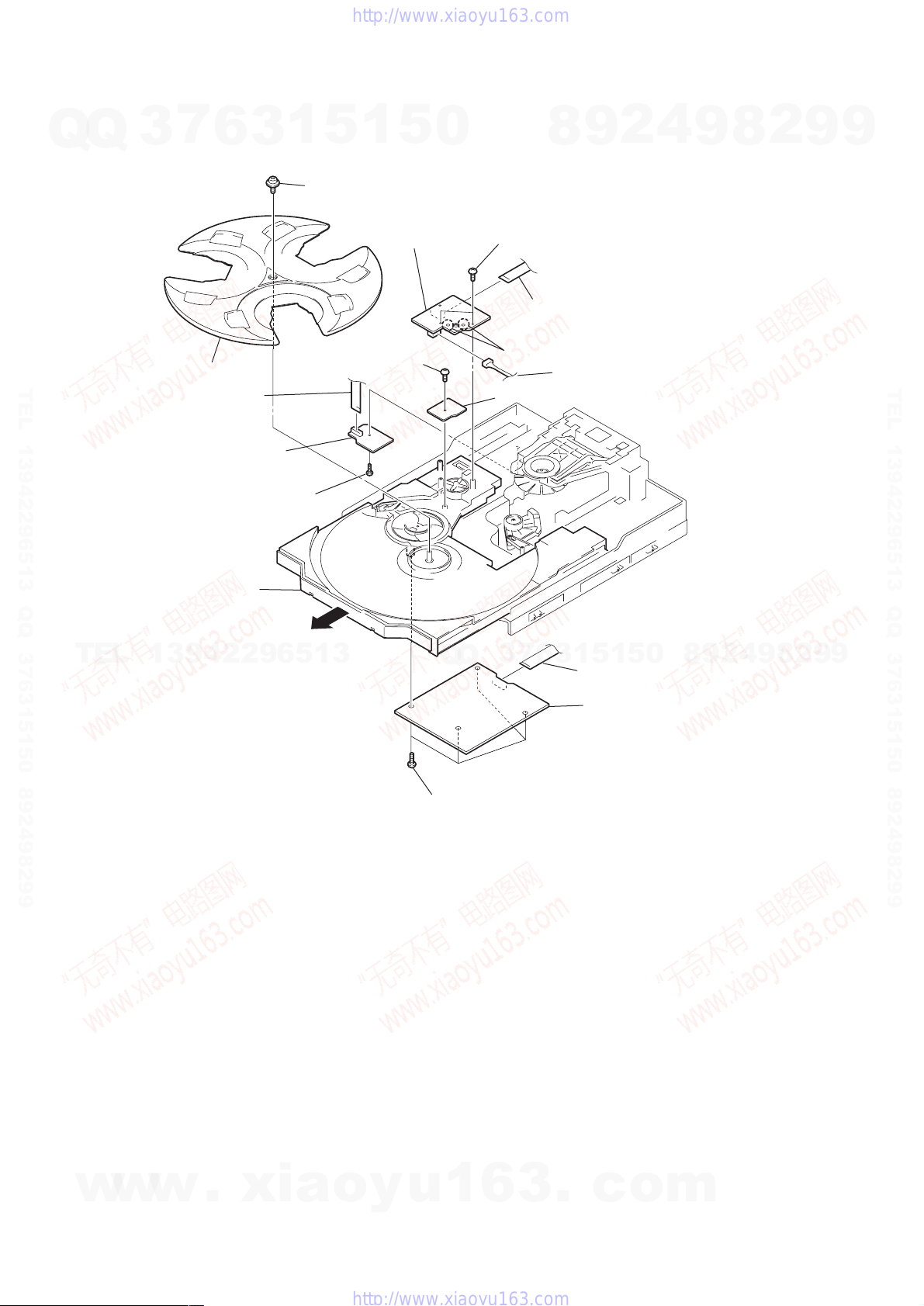
2-8. CD BOARD, DRIVER BOARD, MOTOR BOARD AND ADDRESS SENSOR BOARD
7
Q
Q
TEL 13942296513 QQ 376315150 892498299
3
6
qa
Tray
3
Flat type wire
(8 core)
2
DRIVER board
3
1
5
q;
Screw (+PTPWH 2.6
qs
Screw (+BVTP 2.6
1
8
5
0
×
8)
MOTOR board
×
8)
9
8
4
Two screws (+BVTP 2.6
6
Flat type wire (8 core)
5
Remove two solderings of turn motor (M721).
7
Connector
qd
ADDRESS SENSOR board
2
4
×
2
8
9
8)
9
9
TEL 13942296513 QQ 376315150 892498299
TEL
1
Screw (+BVTP 2.6
9
Pull-out the Table.
13942296513
×
8)
9
9
2
8
9
4
2
9
8
0
5
1
5
1
3
6
7
3
Q
Q
qg
Four
screws
(+BVTP 2.6
×
8)
qf
Flat type wire (16 core)
qh
CD board
10
w
w
w
.
xia
o
y
u
1
6
3
.
c
o
m
SECTION 3
TEST MODE
HCD-DX10/RG4SR/RG20/RG30T
[Change-over of AM Tuner Step between 9 kHz and
Q
TEL 13942296513 QQ 376315150 892498299
10 kHz]
Q
• A step of AM channels can be changed o ver between 9 kHz and
10 kHz.
Procedure:
1. Press ?/1 button to turn the set ON.
2. Select the function “TUNER”, and press TUNER/BAND
button to select the BAND “AM”.
3. Press ?/1 button to turn the set OFF.
4. Press TUNER/BAND and ?/1 buttons simultaneously, and
the display of fluorescent indicator tube changes to “AM 9 k
STEP” or “ AM 10 k STEP”, and thus the channel step is changed
over.
[Cold Reset]
• The cold reset clears all data including preset data stored in the
RAM to initial conditions. Execute this mode when returning
the set to the customer.
Procedure:
1. Press three buttons x , DISPLA Y , and ?/1 simultaneously.
2. The fluorescent indicator tube displays “COLD RESET” and
the set is reset.
[Aging Mode]
This mode can be used for operation check of CD section and tape
deck section.
• If an error occurred:
The aging operation stops and is displayed status.
• If no error occurs:
The aging operation continues repeatedly.
TEL
1. Operating method of Aging Mode
Turn on the main power and select “CD” of the function.
1) Set three discs in tray. Select ALL DISCS, and REPEAT OFF.
2) Load the tapes recording use into both decks.
3) Press three buttons x , DISPLAY , and
DISC SKIP EX-CHANGE simultaneously.
4) Aging operations of CD and tape are started at the same time.
5) To exit the aging mode, perform [Cold Reset].
2. Aging mode in CD section
1) Operation during aging mode
• In the agining mode ,the program is excuted in the following
sequence.
(1) The disc tray opens and closes.
(2) The disc tray turns to select a disc 3.
(3) The pickup accesses to the first track, and plays 3 seconds.
(4) The pickup accesses to the last track, and plays 3 seconds.
(5) The disc tray opens and closes.
(6) The disc tray turns to select a disc 1.
(7) The same operation starts like step (3).
(8) After a disc 1 aging operation, a disc 2 is selected.
(9) When an aging operation of a disc 3 is completed, the display
(10) If no error occurs, the aging operation continues repeatedly.
3
7
6
3
1
13942296513
“AGING
∗∗∗∗” value increases.
5
1
5
0
Q
Q
2) Error display
Display Error
E00D01022 Focus error (No disc)
E00D02022 Sub Q error (Focus is good)
E00D02023 TOC reading error
E00D02014 Access error (Unable within regular time)
Display Error
E00M__E_0 Error during opening tray
E00M__C_2 EX-CHANGE disc error
E00M__D_0 Error during closing tray
E00M__F_3 EX-OPEN error
E00M__D_5 EX-CLOSE error
E00M__C_2 Chuck-up error
E00M__C_3 Unchucking error
3. Aging mode in Tape Deck section
1) Operation during aging mode
• In the agining mode, the program is excuted in the following
sequence.
Step
1
2
3
4
5
6
7
3
7
8
9
10
11
12
2) Error display
• If error occurred, the display remains like “TAPE BAG-2”.
4. Exiting from the aging mode
• Be sure to perform Cold Reset to exit from the aging mode.
4
2
9
8
Mechanism error
Operation
Rewind the TAPE A
Rewind the TAPE B
Play the TAPE A (1 minute)
Stop the TAPE A (1 second)
Play the TAPE A (3 minutes)
Rewind(AMS) the TAPE A
5
1
3
6
F.F.(AMS) the TAPE A
Play the TAPE B (1 minute)
Stop the TAPE B (1 second)
Record the TAPE B (3 minutes)
Rewind(AMS) the TAPE B
F.F.(AMS) the TAPE B
1
5
0
Disc error
9
9
8
8
2
4
2
9
Display
TAPE AAG-1
TAPE BAG-2
TAPE AAG-2
TAPE AAG-3
TAPE AAG-4
TAPE AAG-5
8
9
TAPE AAG-6
TAPE BAG-2
TAPE BAG-3
TAPE BAG-4
TAPE BAG-5
TAPE BAG-6
2
9
9
9
TEL 13942296513 QQ 376315150 892498299
w
w
w
.
xia
o
y
u
1
6
3
.
c
o
m
11
HCD-DX10/RG4SR/RG20/RG30T
[FL T ube Test Mode]
• All fluorecent segments and LEDs are tested.
Q
Q
Procedure:
1. Press ?/1 button to turn the set ON.
2. To enter the test mode, press the three buttons x , DISPLAY
and GROOVE simultaneously.
3. Press DISPLAY and DISC SKIP/EX-CHANGE buttons
simultaneously.
4. All segments and LEDs (without STANDBY LED) are turned
on.
5. To exit from this mode, press ?/1 b utton to turn the set OFF.
[Version and Destination Display Mode]
• The version or destination is displayed.
TEL 13942296513 QQ 376315150 892498299
Procedure:
1. Press ?/1 button to turn the set ON.
2. To enter the test mode, press the three buttons x , DISPLAY
and GROOVE simultaneously.
3. Press DISPLAY and DISC 1 buttons simultaneously.
4. The version is displayed.
5. Press DISPLAY and DISC 2 buttons simultaneously.
6. The destination is displayed.
7. To exit from this mode, press ?/1 b utton to turn the set OFF.
[Key Check Mode]
• Keyboard check.
Procedure:
1. Press ?/1 button to turn the set ON.
2. To enter the test mode, press the three buttons x , DISPLAY
and GROOVE simultaneously.
TEL
3. Press DISPLAY and DISC 3 b uttons simultaneously, and the
key check mode is activated.
4. In the key check mode, the fluorecent indicator displays “KEY
0 VOL 0”. Each time a button is pressed, “KEY 0” value
increases. However, once a button is pressed, it is no longer
taken into account.
“VOL 0” value increases like 1, 2, 3 ... if rotating VOLUME
knob clockwise, or it decreases like 0, 9, 8, ... if rotating counterclockwise.
5. To exit from this mode, press ?/1 b utton to turn the set OFF.
3
7
6
3
1
13942296513
5
1
5
[VACS ON/OFF Mode]
• This mode is used to switch ON and OFF the VACS (Variable
0
Attenuation Control System).
Procedure:
1. Press ?/1 button to turn the set ON.
2. To enter the test mode, press the three buttons x , DISPLAY
and GROOVE simultaneously.
3. Press CD SYNC button while pressing DISPLAY button.
The message “VACS OFF” or “VACS ON” appears.
4. To exit from this mode, press ?/1 button to turn the set OFF.
[Equalizer Test Mode]
• This mode is used to test the function of the equalizer.
Procedure:
1. Press ?/1 button to turn the set ON.
2. To enter the test mode, press the three buttons x , DISPLAY
and GROOVE simultaneously.
3. Press m button while pressing DISPLAY b utton. The message
4. The value increases like + 2, + 4 ... if pressing > button
5. Press M button while pressing DISPLAY b utton. The message
6. The value increases like + 2, + 4 ... if pressing > button
7. To exit from this mode, press ?/1 button to turn the set OFF.
[CD Ship Mode (No Memory Clear) ]
• This mode moves the pickup to the position durable to vibra-
Q
Q
tion. Use this mode when returning the set to the customer after
repair.
Procedure:
1. Press ?/1 button to turn the set ON.
2. Press CD button and ?/1 button simultaneously.
3. The "STANDBY" display blinks instantaneously, and the CD
–
“BASS + 0” is displayed.
while DISPLAY button is still depressed, or it decreases like 2, - 4 ... if pressing . button.
+
“TRE + 0” is displayed.
while DISPLAY button is still depressed, or it decreases like
- 2, - 4 ... if pressing . button.
7
3
ship mode is set.
8
6
3
9
1
5
2
1
5
4
0
9
8
9
8
2
4
2
9
8
9
2
9
9
TEL 13942296513 QQ 376315150 892498299
9
[CD Service Mode]
• This mode can run the CD sled motor freely . Use this mode, for
instance, when cleaning the pickup.
Procedure:
1. Press ?/1 button to turn the set ON.
2. Select the function “CD”.
3. To enter the test mode, press three buttons x , DISPLAY , and
GROOVE simultaneously.
4. Press DISPLAY and OPEN/CLOSE b uttons simultaneously.
5. The CD service mode is selected.
6. With the CD in stop status, press
to outside track, or press m button to inside track.
7. To exit from this mode, perform as follows:
1) Move the pickup to the most inside track.
2) Press ?/1 button to turn the set OFF.
Note: • Always move the pickup to most inside track when exiting from
12
this mode. Otherwise, a disc will not be unloaded.
• Do not run the sled motor excessively , otherwise the gear can be
chipped.
w
w
w
–
.
xia
M
b utton to move the pickup
+
o
y
u
1
6
3
.
c
o
m
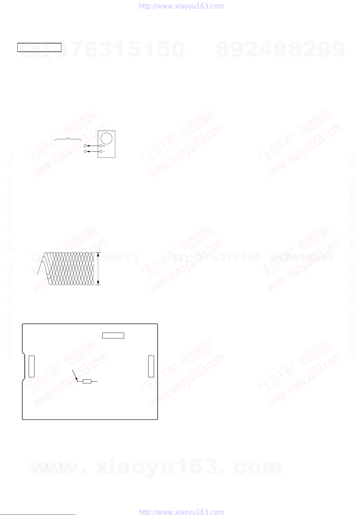
AM RF Signal generator
30% amplitude
modulation by
400Hz signal
output level : as low as possible
AM ANTENNA terminal
(JK101)
set
r
HCD-DX10/RG4SR/RG20/RG30T
SECTION 4
ELECTRICAL ADJUSTMENTS
TUNER SECTION
7
Q
Q
TEL 13942296513 QQ 376315150 892498299
TEL
3
FM Tuned Level Adjustment
FM RF Signal generator
Carrier frequency : 98 MHz
Modulation : AUDIO 1 kHz, 75 kHz
deviation (100%)
Output level : 30 dB (at 75
Procedure:
1. Supply a 98 MHz signal at 28 dB from the ANTENNA terminal.
2. Tune the set to 98 MHz.
3. Adjust RV101 to the point (moment) when the TUNED
indicator will change from going off to going on.
Adjustment Location: MAIN board
Null Adjustment
FM RF Signal generator
Carrier frequency : 98 MHz
Modulation : AUDIO 1 kHz, 75 kHz
deviation (100%)
Output level : 60 dB (at 75
13942296513
6
3
1
75
Ω
75
Ω
Ω
coaxial
open)
Ω
coaxial
open)
5
1
5
FM ANTENNA terminal
(JK101)
FM ANTENNA terminal
(JK101)
set
set
0
Q
Q
AM IF Adjustment
Procedure:
1. Set the frequency of the AM RF signal generator to 1000 kHz
2. Tune the set to AM 1000 kHz (at 10 kHz step) or 999 kHz (at 9
3. Adjust IFT101 so that the reading on level meter becomes in
7
3
4
2
9
8
set
headphones jack (JK601)
(at 10 kHz step) or 999 kHz (at 9 kHz step).
kHz step).
maximum.
8
0
5
1
5
1
3
6
9
16 Ω
9
8
2
4
level mete
9
2
8
9
2
9
9
TEL 13942296513 QQ 376315150 892498299
9
Procedure:
1. Supply a 98 MHz signal at 60 dB from the ANTENNA terminal.
2. Tune the set to 98 MHz.
3. Measure voltage between pin 21 and pin 23 of IC 101. Adjust
Adjustment Location: MAIN board
[MAIN BOARD] Component side
T101 until the voltage becomes 0 V.
T101:NULL
T101
RV101
IFT101 : AM IF
RV101:FM TUNED LEVEL
w
w
w
.
xia
o
y
u
1
6
3
.
c
o
m
13
HCD-DX10/RG4SR/RG20/RG30T
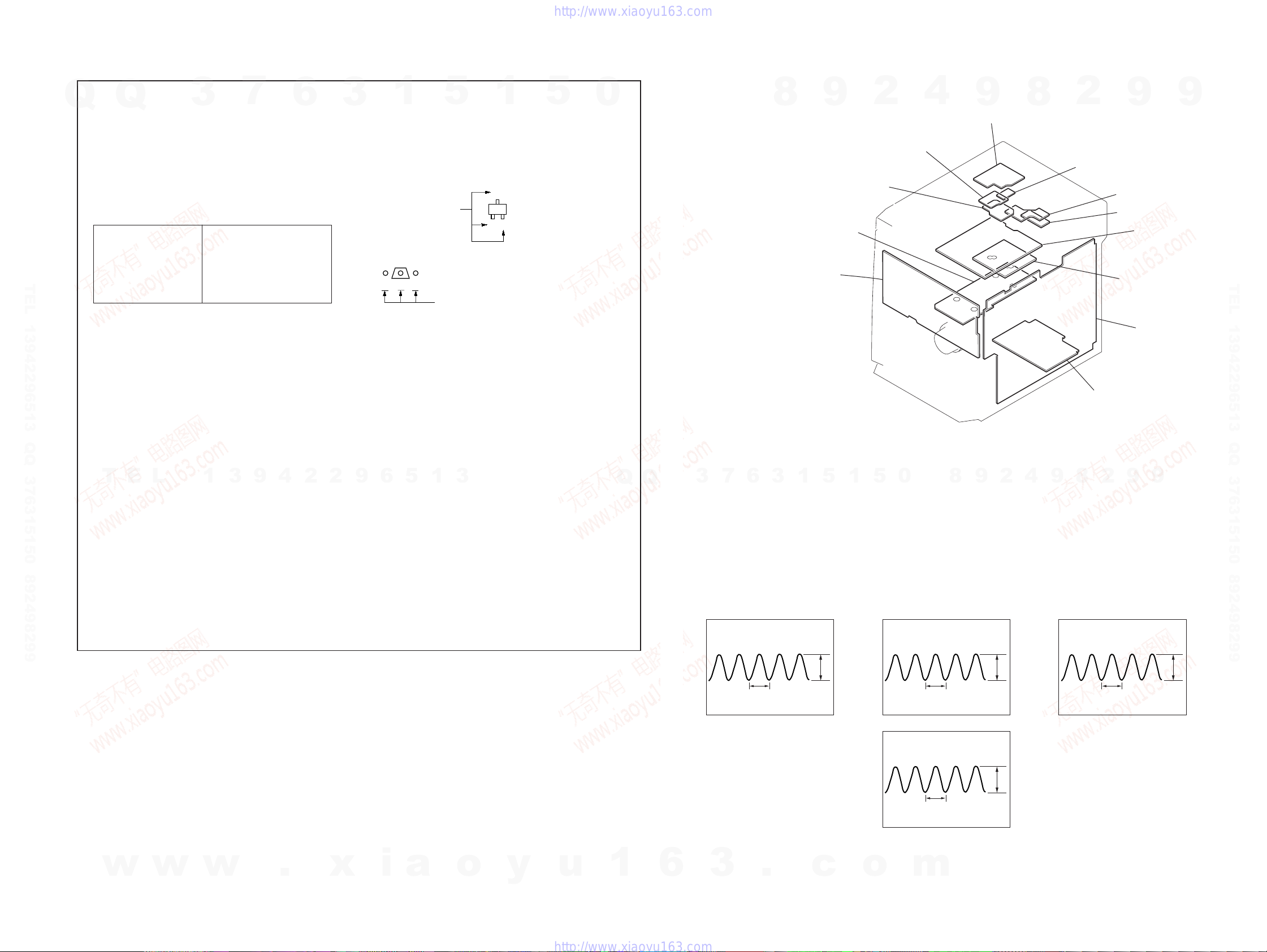
CD SECTION
7
Q
Q
Note :
1. CD Block is basically designed to operate without adjustment.
Therefore, check each item in order given.
2. Use YEDS-18 disc (3-702-101-01) unless otherwise indicated.
3. Use an oscilloscope with more than 10MΩ impedance.
4. Clean the object lens by an applicator with neutral detergent
when the signal level is low than specified value with the
following checks.
RF Level Check
TEL 13942296513 QQ 376315150 892498299
Procedure :
1. Connect oscilloscope to pin q; (IC751).
2. Turned Power switch on.
3. Load a disc (YEDS-18) and playback.
4. Confirm that oscilloscope waveform is clear and check RF signal
level is correct or not.
3
CD board
IC751 pin q;
GND
6
oscilloscope
3
1
5
1
5
0
8
9
2
4
9
8
2
9
9
TEL 13942296513 QQ 376315150 892498299
Note : Clear RF signal wavefor m means that the shape “ ◊ ” can be clearly
distinguished at the center of the waveform.
RF signal waveform
VOLT/DIV : 200mV
TIME/DIV : 500ns
TEL
Adjustment Location: CD board
[CD BOARD] (Component Side)
CN731
13942296513
level : 1.4 to 2.1 Vp-p
CN732
CN733
TP connected to pin q; (IC751)
C746A
Q
Q
3
7
6
3
1
5
1
5
0
8
9
2
4
9
8
2
9
9
14
w
w
w
.
xia
o
y
u
1
6
3
.
c
o
m
SECTION 5
DIAGRAMS
HCD-DX10/RG4SR/RG20/RG30T
5-1. CIRCUIT BOARD LOCATION
THIS NOTE IS COMMON FOR PRINTED WIRING BOARDS AND SCHEMATIC DIAGRAMS.
Q
TEL 13942296513 QQ 376315150 892498299
Q
(In addition to this, the necessary note is printed in each bloc k.)
Note on Schematic Diagram:
• All capacitors are in µF unless otherwise noted. pF: µµF
50 WV or less are not indicated except for electrolytics
and tantalums.
• All resistors are in Ω and 1/
specified.
f
•
• C : panel designation.
• A : B+ Line.
• B : B– Line.
• H : adjustment for repair.
• Voltages and waveforms are dc with respect to ground
• V oltages are taken with a VOM (Input impedance 10 MΩ).
• Waveforms are taken with a oscilloscope.
• Circled numbers refer to waveforms.
• Signal path.
: internal component.
Note:
The components identified by mark 0 or dotted
line with mark 0 are critical for safety.
Replace only with part
number specified.
under no-signal (detuned) conditions.
Voltage variations may be noted due to normal produc-
tion tolerances.
no mark : FM
< >: CD
[ ] : T APE
Voltage variations may be noted due to normal production tolerances.
T
E
F : FM
E : PB (DECK A)
d : PB (DECK B)
G : REC (DECK B)
J : CD
L
3
1
7
4
W or less unless otherwise
Note:
Les composants identifiés par
une marque 0 sont critiques
pour la sécurité.
Ne les remplacer que par une
piéce portant le numéro
spécifié.
3
9
4
6
2
2
3
9
1
Note on Printed Wiring Boards:
• X : parts extracted from the component side.
• b : Pattern from the side which enables seeing.
• Indication of transistor.
These are omitted.
Q
B
CE
• Abbreviation
CND : Canadian model
AUS : Australian model
AR : Argentina model
SP : Singapore model
TW : T aiw an model
MX : Mexican model
MY : Malaysia model
E2 : 120V AC Area in E model
E3 : 240V AC Area in E model
E51 : Chilean and Peruvian model
6
5
1
5
These are omitted.
1
C
Q
B
E
3
5
0
Q
Q
3
7
6
8
TRANS board
PANEL board
1
3
9
ADDRESS SENSOR board
DRIVER board
1
5
2
5
0
4
9
MOTOR board
9
8
2
8
4
2
VIDEO OUT board
POWER board
8
9
9
SPDL board
SENSOR board
CD board
SUB TRANS board
MAIN board
9
9
2
9
TEL 13942296513 QQ 376315150 892498299
w
w
w
.
x
i
a
o
y
u
1
6
• WA VEFORMS
1
IC751 rf (XOUT)
59 ns
3
.
4.9Vp-p
c
o
– MAIN BOARD – – PANEL BOARD –– CD BOARD –
2
IC102 wf (XOUT)
222 µs
3
L251
16.6 µs
(60.1 kHz)
m
3.2Vp-p
14.1Vp-p
4
IC601 qj (XTAL 6.0MHz)
167 ns
4.8Vp-p
1515
HCD-DX10/RG4SR/RG20/RG30T
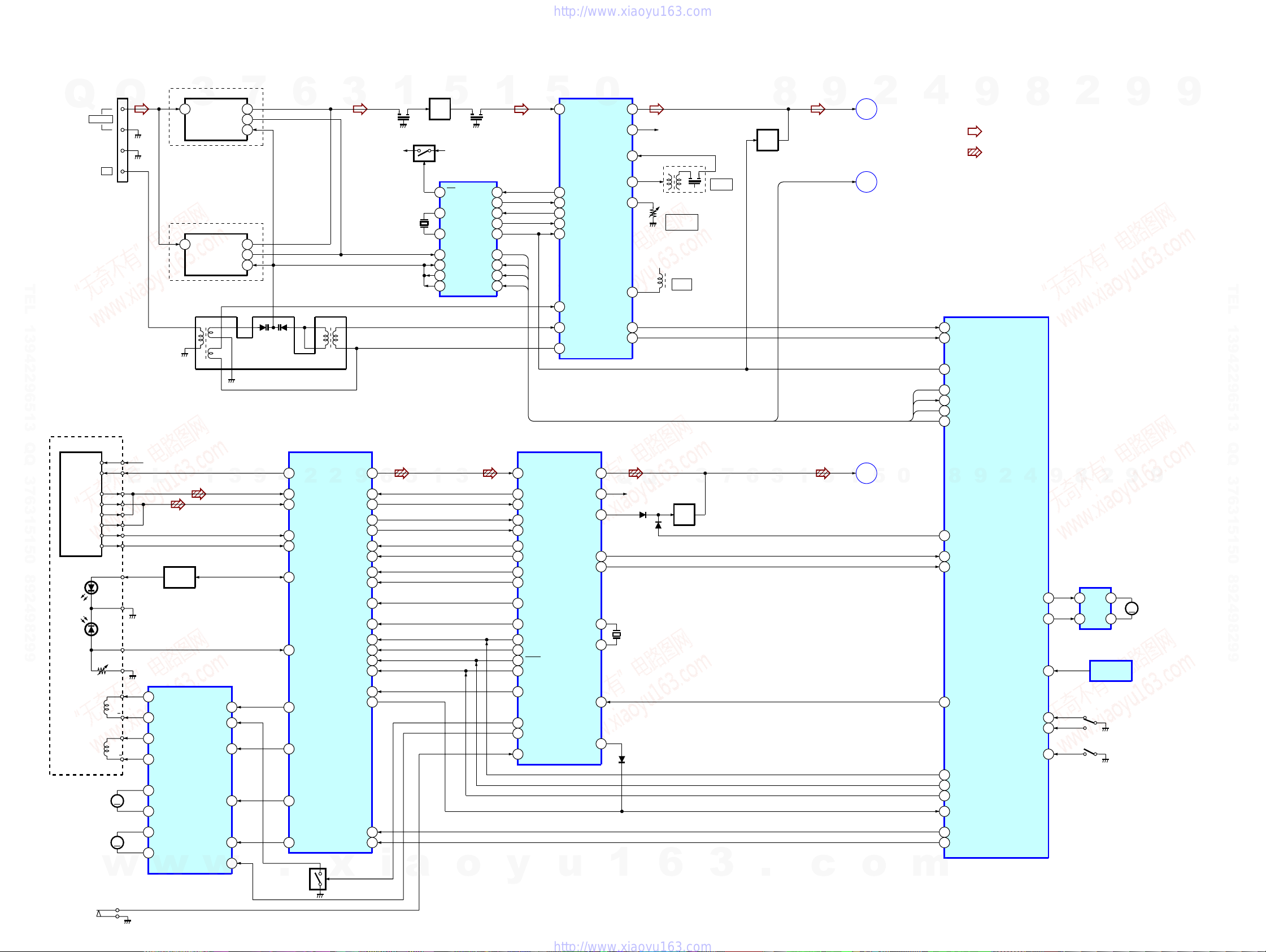
5-2. BLOCK DIAGRAMS
TUNER/CD SECTION
EXCEPT RG20:AEP,UK
Q
JK101
Q
FM 75Ω
G
AM
3
1
ANT IN
RG20:AEP,UK
1
ANT IN
FND1
OSC OUT
FND1
IF OUT
7
VT
7
8
5
7IF OUT
8OSC OUT
5VT
6
3
TEL 13942296513 QQ 376315150 892498299
1
3
4
13
RB101
14
55
1511
67
9
CX101
Q102
Q101
RF IF
AMP
10
24
15
18
17
19
1
5
FM
XIN
XOUT
FM OSC
VT1 IN
VT1
PD1
PLL
IC102
FM/AM IF
AM OSC
1
CF101 CF102
+B TU+12V
4.5MHz
FM
CL
CE
1
12
7
14
2VCO STOP
8IF REQ
6DO
4DI
5
3
DI
DO
CLK
CE
AM/FM IF MPX
1
FM IF
9
IF OUT
12
AM/IF
24
AM OSC
13
VCO STOP
8
IF REQ MUTE
20
AM RF IN
22
AM OSC
23
V REG
IC101
0
L OUT
R OUT
AM MIX OUT
FM SD ADJ
FMDET
TUNED
STEREO
11
10
18AM IF IN
19
R-CH
IFT101
3
5
6
7
+6.8V
RV101
FM TUNED
LEVEL
T101
NULL
5
AM IF
Q106
MUTE
8
9
L-CH
DO,CLK
A
MAIN
SECTION
C
MAIN
SECTION
2
4
9
• R-CH is omitted due to same as L-CH
• Signal Path
: FM
: CD
MASTER CONTROL
IC601(1/2)
TUNED
10
TU STEREO
9
8
2
9
9
TEL 13942296513 QQ 376315150 892498299
OPTICAL PICK-UP
BLOCK
(KSM-213-DCP/Z-NP)
DETECTOR
VCC
VC
T
A
B
C
D
E
F
LD
GND
PD
VR
F+
FOCUS
COIL
TRACKING
COIL
SLED
MOTOR
F
T+
T
M
E
+5V
L
1
CH1 OUTA
2
CH1 OUTB
27
CH4 OUTA
26
CH4 OUTB
11
CH21 OUTB
12
CH2 OUTA
Q731
LD
DRIVER
FCS/TRK COIL
SL/SP MOTOR
DRIVER
IC781
1
CH1 INA
CH1 INB
CH4 INA
CH2 INB
122
3
3
4
25
9
9
4
TUNER MUTE OUT
77
DO
LC72131 BU2114 DO
95
DI
LC72131 DI
96
CLK
CLK
97
CE
LC72131 CE
93
ASP
IC731
58
VR
2
2
2
FIN 1
1
FIN 2
3
E
4
F
62
LDD
63
LDS
16
FD
15
TO
29
SLD
9
DEF
TES
HFL
JP+
JP-
CV+
CV-
SLOF
DATA
DRF
41RF SM
6
5
1
3
44SLI
49
36
37
33
32
40
39
35TOFF
38
52
50CLK
51CL
53CE
34TGL
54
10
9
1
16
15
19
20
12
13
17
14
56
61
57
54
18
28
26
27
DSP
IC751
EFMI
EFMO
DEF
TES
HFL
JP+
JP-
CLV+
CLV-
TOFF
VP
COIN
4.2M
CQCK
RWC
TGL
SHUTER IN/OUT
D MUTE
LIMIT SW
L CH
WRQE
SQ0UT
PDO
37
40R CH
35L MUTE
53
55
45XI
XO
44
58RESET
3
Q
Q
R CH
D733
D735
X701
16.9344M
D732
3
Q771,773
MUTE
7
6
3
1
5
CD-L
1
SECTION
B
MAIN
5
0
8
CD A MUTE
6
CD WRQ
7
SQOUT
99
CD RESET OUT
3
COIN
98
SQCK
100
CD RWC
2
CD DRF
8
2
9
CD MOTOR-
CD NUMBER SENSOR
CD PIC UP/DOWN SW
4
9
9
2
8
9
IC701
73CD MOTOR +
9
4
MOTOR
74
68
70CD TRAY OPEN SW
71CD TRAY CLOSE SW
69
DRIVE
7
TBL ADDRESS
2
IC711
SENSOR
M
S701
OPEN/CLOSE
S711
BU UP/
DOWN
M721
TURN
MOTOR
SPINDLE
MOTOR
S01
LIMIT
M
w
18
CH3 OUTB
17
CH3 OUTA
w
CH3 INB
20
MUTE
w
SL+
27
SPD
7
.
Q775
x
SL-
31
30
i
a
o
y
u
1
6
3
.
c
o
m
5
4
CD SL+
CD SL-
1616
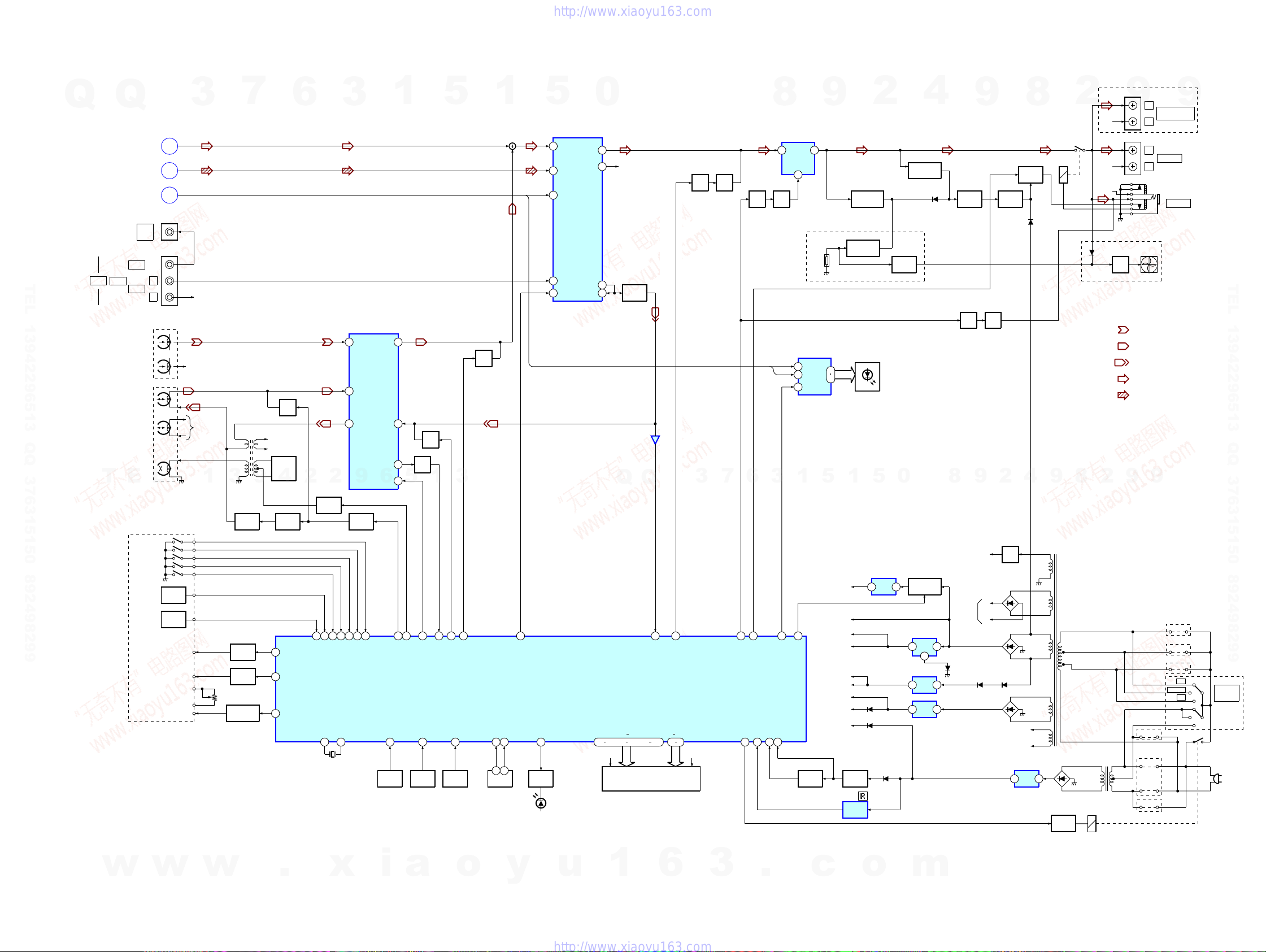
MAIN SECTION
7
3
Q203,205
PLAY/REC
CONTROL
Q604,607
A TRIG
DRIVE
Q603,606
B TRIG
DRIVE
Q605,608
CAP MOTOR
DRIVE
L251
BIAS
9
R-CH
Q201
MUTE
BIAS
OSC
Q214
4
Q209
PLAY/REC
SWITCH
81
TAPE SOL A
82
TAPE SOL B
80
MECHA VCC
6
2
2
Q210,213
BIAS
SWITCH
28
27
26
67
PHOTO SENSOR A
PHOTO SENSOR B
TAPE FWD REC SW B
XTAL 6.0MHZ
16
17
X601
6MHz
3
PB/REQ EQ AMP
CH1/A
1
CH1/B
2
REC OUT
9
9
Q211,212
SWITCH
66
TAPE B HALF25TAPE A HALF
XTAL 6.0MHZ
A
B
C
JK602
JK603
A PHOTO
SENSOR
B PHOTO
SENSOR
MOTOR H
MOTOR L
3
L-CH
LOUT
DO,CLK
R-CH
R-CH
R-CH
1
A SOL
B SOL
SFR601
CAP M+
Q
TEL 13942296513 QQ 376315150 892498299
INPUT
T
Q
SECTION
SECTION
SECTION
VIDEO
AUDIO
REC/PB
HEAD
ERASE
E
A MODE
B MODE
A HALF
B HALF
REC(FWD)
TUNER
CD
TUNER
VIDEO
OUT
LGAME
R
DECK-A
PB
HEAD
DECK-B
HEAD
L
MECHA DECK
IC201
PRE OUT
REC IN
MIX OUT
6
TAPE A/B
65
TAPE MODE SW B
TAPE MODE SW A
19
FUCTION
KEY
S601-609
1
5
11
6
19
86
KEY INPUT0
Q320,321
5
88
TAPE REC
TAPE BIAS
S612-620
AMS
91
20
FUCTION
KEY
Q207
MUTE
1
24
AMS IN
TAPE A/B
KEY INPUT1
5
3
87
TAPE REC MUTE
KEY INPUT2
21
FUCTION
KEY
S623-629
Q215
MUTE
79
TAPE MUTE OUT (PB)
VOLUME
VR601
1
VR ENCODER A
VR ENCODER B
13
14
31
5
CLK
94
MASTER CONTROL
BD3871 DATA/LATCH
POWER SW
84
Q651
LED
DRIVER
0
AUDIO SOUND
PROCESSOR
IC301
B1
7
OUT1
17
A1
5
SC
13
C1
9
SI
14
IC601(2/2)
LED601
(POWER)
OUT2
SEL1
MN1
R-CH
16
Q303
4
BUFFER
1
3
IC302
1
Q
Q
22
SPEANA IN L
FLD601
FLOURESCENT
INDICATOR TUBE
1G 10G
39 33
P1 P22
..
47 50 52 6340 45
VF VF
Q803,804
MUTE
CONT
3
76
SYSTEM MUTE OUT
Q316
MUTE
7
6
78
STK MUTE
83
Q503,504
MUTE
CONT
75
SPK RELY ON
POW SAVE
REMOTE IN
29
8
1
Q581
MUTE
DO
CLK
3
92
RESET
POWER DOWN IN
12
11
IC501
POWER
AMP
12
RG30T/RG4SR
TH501
IC602
1
DRIVER
2
3
1
1
CD ON/OFF
BU2114 LATCH
Q602 Q601
RESET
SWITCH
6
LED
9
16
13
5
CD +5V
FAN +B
LED +5.6V
TU +B
TU +12V
TC +12V
M +9V
CD +7V
µCOM +B
1
RESET
RM601
REMOTE
Q501
OVER LOAD
DETECTOR
Q582,583
OVER HEAT
DETECTOR
LED602-609
D809 -810
D601
2
5
+5V
3
REG
IC804
D602
Q584
FAN ON
SWITCH
0
1
Q308,309
PROTECT
DETECTOR
Q801,802
CD POWER
SWITCH
IC803
+5V
3
REG
2
IC802
+12V
3
REG
IC801
+9V
3
REG
4
D502
1
1
1
8
D811
Q311
PROTECT
CONT
Q305
MUTE
CONT
POWER
AMP
9
Q306
MUTE
9
-VP
+B
-B
D543 D542
EVER +5.6V
HCD-DX10/RG4SR/RG20/RG30T
RG4SR
JK311
9
R CH
JK310
R CH
R CH
RG30T,RG4SR
D852
Q850,851
FAN
DRIVE
• R-CH is omitted due to same as L-CH
• Signal Path
9
2
T901
SUB TRANS
L
SURROUND SPK
OUTPUT
R
L
SPEAKER
R
JK601
PHONES
FAN
(M961)
: PB (DECK A)
: PB (DECK B)
: REC (DECK B)
: FM
: CD
9
DX10:AR,AUS
JW7
RG20:AEP,UK
JW6
DX10:MX/RG20:US,CND
/RG30T/RG4SR
DX10:MX
DX10:AR,AUS/RG20
/RG30T/RG4SR
DX10:MX,MY,SP,
JW5
220/230
JW2
JW3
JW1
JW4
TW,E2,E3,E51
9
240
120
Q312
PROTECT
SWITCH
2
Q911
-30V
REG
D541
D801-804
D812-815
3
8
Q314,315
RELAY
DRIVE
4
VF
VF
IC901
+5.6V
REG
D311
MAIN TRANS
1
RL1
9
T911
D902-905
Q901
RELAY
DRIVE
2
8
RY901
TEL 13942296513 QQ 376315150 892498299
S901
VOLTAGE
SELECTOR
DX10:MY,SP,
TW,E2,
E3,E51
AC
IN
w
w
w
.
x
i
a
o
y
u
1
6
3
1717
.
c
o
m
 Loading...