

Sony HCD-NEZ30 - Cd Deck Receiver Component Service Manual
SERVICE MANUAL
COMPACT DISC DECK RECEIVER
HCD-NEZ30
Ver. 1.5 2007.04
SPECIFICATIONS
9-887-030-06
2007D05-1
© 2007.04
Sony Corporation
Personal Audio Division
Published by Sony Techno Create Corporation
US Model
Canadian Model
UK Model
E Model
East European Model
• HCD-NEZ30 is the amplifier, CD player, tape deck
and tuner section in CMT-NEZ30.
Model Name Using Similar Mechanism HCD-NEZ3
CD Section Base Unit Name BU-K8BD83S-WOD
Optical Pick-up block Name KSM-213CDP
TAPE Section
Model Name Using Similar Mechanism NEW
Tape Transport Mechanism Type CMAL5Z235A
AUDIO POWER SPECIFICATIONS
POWER OUTPUT AND TOTAL HARMONIC DISTORTION:
( The United States model only)
With 6 ohm loads, both channels driven, from 120 – 10,000 Hz; rated 15 watts
per channel minimum RMS power, with no more than 10% total harmonic
distortion from 250 milliwatts to rated output.
Amplifier section
North-American model:
Continuous RMS power output (reference): 15 + 15 W (6 ohms at 1 kHz,
10% THD)
European model:
DIN power output (rated): 11 + 11 W (6 ohms at 1 kHz, DIN)
Continuous RMS power output (reference): 17 + 17 W (6 ohms at 1 kHz,
10% THD)
Music power output (reference): 28 + 28 W
The following are measured at AC 220 V, 50/60 Hz (Argentine model), AC
120 V, 60 Hz (Mexican model), AC 120, 220 or 230 – 240 V, 50/60 Hz (other
models)
DIN power output (rated): 11 + 11 W (6 ohms at 1 kHz, DIN)
Continuous RMS power output (reference): 15 + 15 W (6 ohms at 1 kHz,
10% THD)
Inputs
AUDIO IN: Sensitivity 250 mV, impedance 47 kilohms
Outputs
PHONES: Accepts headphones with an impedance of 8 ohms or more
SPEAKER: Accepts impedance of 6 to 16 ohms
CD player section
System: Compact disc and digital audio system
Laser Diode Properties
Emission Duration: Continuous
Laser Output*: Less than 44.6µW
* This output is the value measurement at a distance of 200 mm from the
objective lens surface on the Optical Pick-up Block with 7mm aperture.
Tape deck section
Recording system: 4-track 2-channel, stereo
AM tuner section:
Tuning range
Pan-American model: 530 – 1,710 kHz (with 10 kHz tuning interval)
531 – 1,710 kHz (with 9 kHz tuning interval)
Other models: 530 – 1,710 kHz (with 10 kHz tuning interval)
European models: 531 – 1,602 kHz (with 9 kHz tuning interval)
531 – 1,602 kHz (with 9 kHz tuning interval)
Antenna: AM loop antenna, external antenna terminal
Intermediate frequency: 450 kHz
General
Power requirements
North American model: AC 120 V, 60 Hz
Mexican model: AC 120 V, 60 Hz
European model: AC 230 V, 50/60 Hz
Argentine model: AC 220 V, 50/60 Hz
Other models: AC 120, 220 or 230 – 240 V, 50/60 Hz
Adjustable with voltage selector
Power consumption:
North American model: 45 watts
Other models: 45 watts
Dimensions (w/h/d) (excl. speakers):
Mass (excl. speakers):
North
Approx. 164 × 235 × 265 mm
American model: Approx. 3.2 kg
European model: Approx. 3.6 kg
Other models: Approx. 3.3 kg
Design and specifications are subject to change without notice.
Tuner section
FM stereo, FM/AM superheterodyne tuner
FM tuner section:
Tuning range
North American model: 87.5 – 108.0 MHz (100 kHz step)
Other models: 87.5 – 108.0 MHz (50 kHz step)
Antenna: FM lead antenna
Antenna terminals: 75 ohms unbalanced
Intermediate frequency: 10.7 MHz
HCD-NEZ30
r
(0.75 V)
To Exposed Metal
Parts on Set
Earth Ground
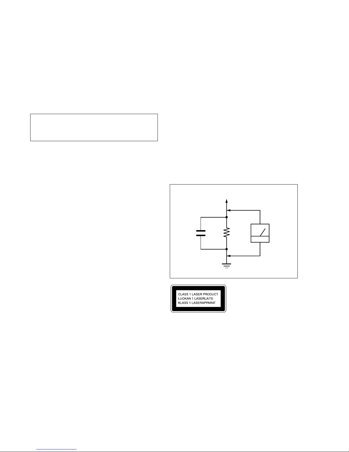
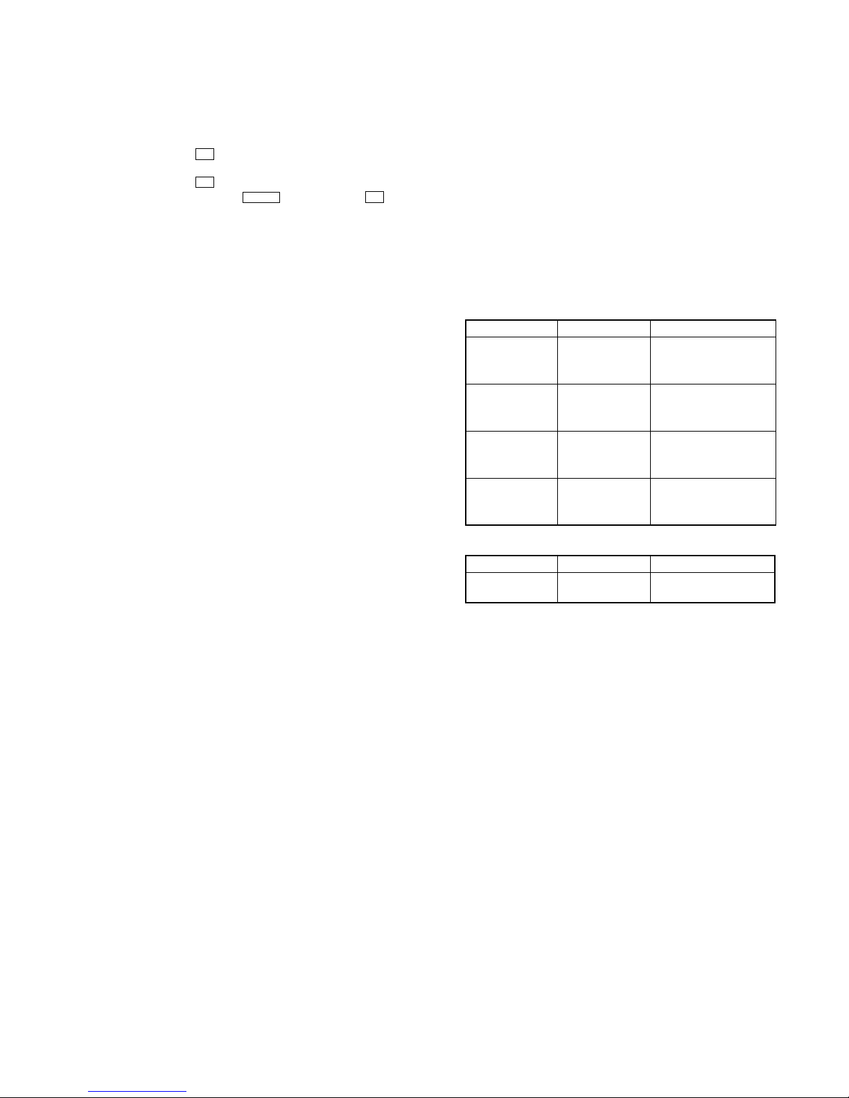
LEAKAGE TEST
The AC leakage from any exposed metal part to earth ground and
from all exposed metal parts to any exposed metal part having a
return to chassis, must not exceed 0.5 mA (500 microamperes.).
Leakage current can be measured by any one of three methods.
1. A commercial leakage tester, such as the Simpson 229 or RCA
WT-540A. Follow the manufacturers’ instructions to use these
instruments.
2. A battery-operated AC milliammeter. The Data Precision 245
digital multimeter is suitable for this job.
3. Measuring the voltage drop across a resistor by means of a
VOM or battery-operated AC voltmeter. The “limit” indication
is 0.75 V, so analog meters must have an accurate low-voltage
scale. The Simpson 250 and Sanwa SH-63Trd are examples
of a passive VOM that is suitable. Nearly all battery operated
digital multimeters that have a 2 V AC range are suitable. (See
Fig. A)
classified as a CLASS
This appliance is
1 LASER product. This
marking is located on the
rear exterior.
Notes on chip component replacement
• Never reuse a disconnected chip component.
• Notice that the minus side of a tantalum capacitor may be
damaged by heat.
Flexible Circuit Board Repairing
• Keep the temperature of the soldering iron around 270 ˚C
during repairing.
• Do not touch the soldering iron on the same conductor of the
circuit board (within 3 times).
• Be careful not to apply force on the conductor when soldering
or unsoldering.
CAUTION
Use of controls or adjustments or performance of procedures
other than those specified herein may result in hazardous radiation
exposure.
SAFETY CHECK-OUT
After correcting the original service problem, perform the following
safety check before releasing the set to the customer:
Check the antenna terminals, metal trim, “metallized” knobs, screws,
and all other exposed metal parts for AC leakage.
Check leakage as described below.
SAFETY-RELATED COMPONENT WARNING!!
COMPONENTS IDENTIFIED BY MARK 0 OR DOTTED LINE
WITH MARK 0 ON THE SCHEMATIC DIAGRAMS AND IN
THE PARTS LIST ARE CRITICAL TO SAFE OPERATION.
REPLACE THESE COMPONENTS WITH SONY PARTS WHOSE
PA RT NUMBERS APPEAR AS SHOWN IN THIS MANUAL OR
IN SUPPLEMENTS PUBLISHED BY SONY.
AC
0.15 µF
1.5 k
Ω
voltmete
Fig. A. Using an AC voltmeter to check AC leakage.
ATTENTION AU COMPOSANT AYANT RAPPORT
LES COMPOSANTS IDENTIFIÉS PAR UNE MARQUE 0 SUR
LES DIAGRAMMES SCHÉMATIQUES ET LA LISTE DES
PIÈCES SONT CRITIQUES POUR LA SÉCURITÉ DE
FONCTIONNEMENT. NE REMPLACER CES COM- POSANTS
QUE PAR DES PIÈCES SONY DONT LES NUMÉROS SONT
DONNÉS DANS CE MANUEL OU DANS LES SUPPLÉMENTS
PUBLIÉS PAR SONY.
À LA SÉCURITÉ!
2
HCD-NEZ30
SECTION 1
SERVICING NOTES
Ver. 1.5
TABLE OF CONTENTS
1. SERVICING NOTES ............................................... 3
2. GENERAL ................................................................... 6
3. DISASSEMBLY
3-1. Disassembly Flow ........................................................... 8
3-2. Cabinet............................................................................. 8
3-3. Cabinet (Top) Section ...................................................... 9
3-4. Base Unit (BU-K8BD83S-WOD) ................................... 9
3-5. Front Panel Section ......................................................... 10
3-6. Mechanical Deck (CMAL5Z235A) ................................ 10
3-7. MAIN Board .................................................................... 11
3-8. Tuner (FM/AM) ............................................................... 11
4. TEST MODE .............................................................. 12
5. MECHANICAL ADJUSTMENTS ....................... 13
6. ELECTRICAL ADJUSTMENTS ......................... 14
7. DIAGRAMS
7-1. Block Diagram – CD SERVO Section – ......................... 17
7-2. Block Diagram – MAIN Section – .................................. 18
7-3. Printed Wiring Board – CD Board – ............................... 20
7-4. Schematic Diagram – CD Board – .................................. 21
7-5. Printed Wiring Boards – MAIN Section – ...................... 22
7-6. Schematic Diagram – MAIN Section (1/2) – .................. 23
7-7. Schematic Diagram – MAIN Section (2/2) – .................. 24
7-8. Printed Wiring Board – PANEL Board – ........................ 26
7-9. Schematic Diagram – PANEL Board – ........................... 27
7-10. Printed Wiring Boards – DC Section – ........................... 28
7-11. Printed Wiring Board – AC Board – ................................ 29
7-12. Schematic Diagram – POWER SUPPLY Section – ........ 30
8. EXPLODED VIEWS
8-1. Cabinet Section ................................................................ 36
8-2. Mechanical Deck Section ................................................ 37
8-3. Panel Board Section ........................................................ 38
8-4. Cabinet (Top) Section ...................................................... 39
8-5. MAIN Board Section ....................................................... 40
8-6. AC Board, DC Board Section ......................................... 41
NOTES ON HANDLING THE OPTICAL PICK-UP
BLOCK OR BASE UNIT
The laser diode in the optical pick-up block may suffer electrostatic
break-down because of the potential difference generated by the
charged electrostatic load, etc. on clothing and the human body.
During repair, pay attention to electrostatic break-down and also
use the procedure in the printed matter which is included in the
repair parts.
The flexible board is easily damaged and should be handled with
care.
NOTES ON LASER DIODE EMISSION CHECK
The laser beam on this model is concentrated so as to be focused on
the disc reflective surface by the objective lens in the optical pickup block. Therefore, when checking the laser diode emission,
observe from more than 30 cm away from the objective lens.
UNLEADED SOLDER
Boards requiring use of unleaded solder are printed with the leadfree mark (LF) indicating the solder contains no lead.
(Caution: Some printed circuit boards may not come printed with
the lead free mark due to their particular size)
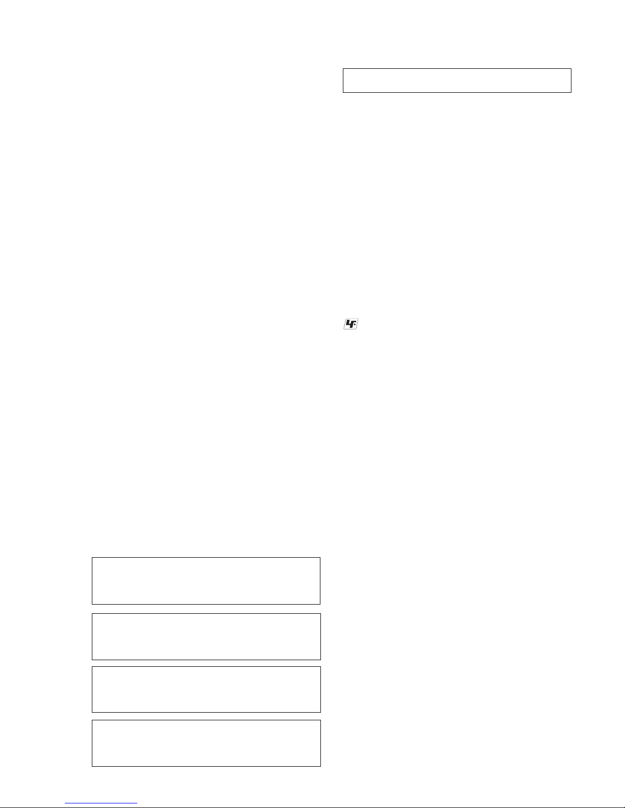
: LEAD FREE MARK
Unleaded solder has the following characteristics.
• Unleaded solder melts at a temperature about 40 ˚C higher
than ordinary solder.
Ordinary soldering irons can be used but the iron tip has to be
applied to the solder joint for a slightly longer time.
Soldering irons using a temperature regulator should be set to
about 350 ˚C.
Caution: The printed pattern (copper foil) may peel away if
the heated tip is applied for too long, so be careful!
• Strong viscosity
Unleaded solder is more viscou-s (sticky, less prone to flow)
than ordinary solder so use caution not to let solder bridges
occur such as on IC pins, etc.
• Usable with ordinary solder
It is best to use only unleaded solder but unleaded solder may
also be added to ordinary solder.
9. ELECTRICAL PARTS LIST................................ 42
Refer to SUPPLEMENT-1 for the MAIN board of printed wiring board,
schematic diagram and electrical parts list of except US and Canadian
models.
When repairing the set of US and Canadian models, refer to either of
original service manual/SUPPLEMENT-1 according to the set.
Refer to SUPPLEMENT-1 for the CD board of printed wiring board,
schematic diagram and electrical parts list of UK and East European
models.
When repairing the set of except UK and East European models, refer to
either of original service manual/SUPPLEMENT-1 according to the set.
Refer to SUPPLEMENT-2 for the HEAD PHONE board of printed wiring
board, schematic diagram and electrical parts list of UK and East European
models.
When repairing the set of except UK and East European models, refer to
either of original service manual/SUPPLEMENT-2 according to the set.
Refer to SUPPLEMENT-3 for the PANEL board of printed wiring board,
schematic diagram and electrical parts list of UK and East European
models.
When repairing the set of except UK and East European models, refer to
either of original service manual/SUPPLEMENT-3 according to the set.
3
HCD-NEZ30
S820
Ver. 1.5
MODEL IDENTIFICATION
– Rear View –
Model Name Part No.
E model 2-665-907-0[]
Mexican model 2-665-908-0[]
Chilean and Peruvian models 2-665-909-0[]
Argentina model 2-665-910-0[]
US and Canadian models 2-665-913-0[]
UK model 3-100-772-0[]
East European model 3-312-856-0[]
Part No.
NOTE WHEN PARTS RELATED TO POWER
TRANSFORMER ARE REPLACED
In this set, the main power transformer (T902) and sub power
transformer (T901) of US and Canadian models have been changed
in the midway of production.
The mount parts on DC board and Part No. of DC board have been
changed along with it.
Perform after confirming which type set when you repair set because
there is a suited combination.
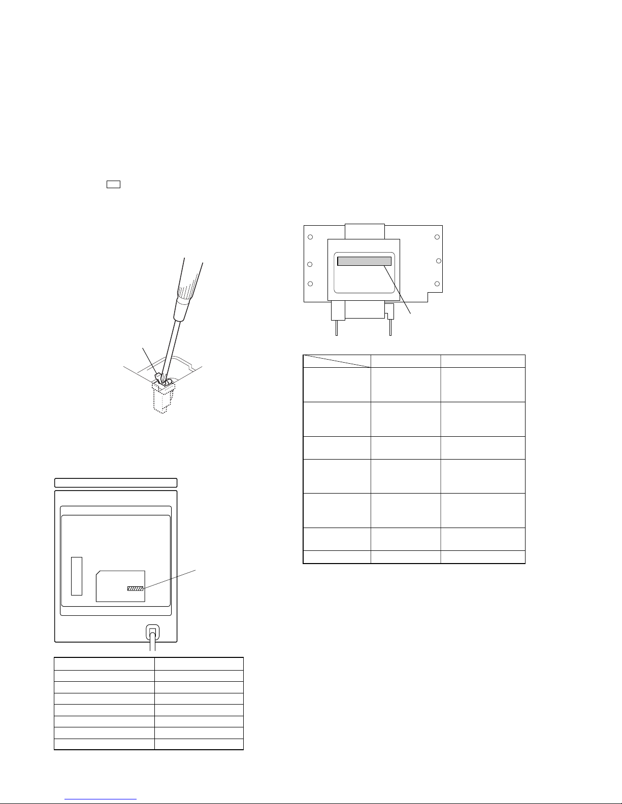
• DISCRIMINATION
Distinguish by the print of label pasted to side of main power
transformer (T902).
– MAIN POWER TRANSFORMER (T902) –
• Combination
TYPE A TYPE B
POWER 1-443-902-11 1-443-903-11
TRANSFORMER TRANSFORMER, TRANSFORMER,
(T902) POWER POWER
T901 1-443-833-11 1-443-846-11
(on AC board) TRANSFORMER, TRANSFORMER,
POWER POWER
D921 NO MOUNT 6-501-193-01
(on DC board) DIODE 1SS355WTE-17
R911 1-216-841-11 1-216-829-11
(on DC board) METAL CHIP METAL CHIP
47K 5% 1/10W 4.7K 5% 1/10W
R912 1-216-841-11 1-216-845-11
(on DC board) METAL CHIP METAL CHIP
47K 5% 1/10W 100K 5% 1/10W
R920 NO MOUNT 1-216-864-11
(on DC board) SHORT CHIP 0
DC board A-1158-136-A A-1216-850-A
1-443-902-11: TYPE
A
1-443-903-11: TYPE
B
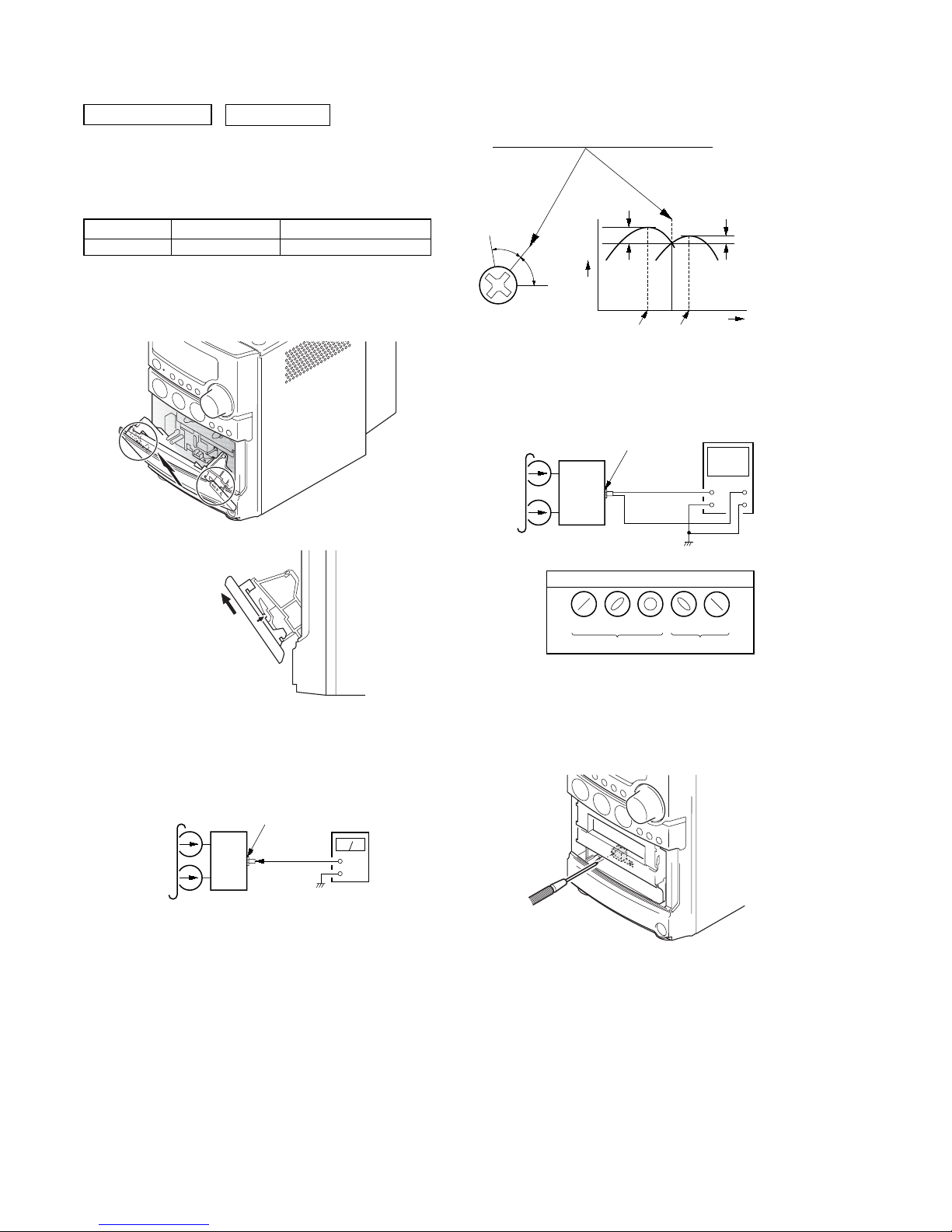
LASER DIODE AND FOCUS SEARCH OPERATION
CHECK
During normal operation of the equipment, emission of the laser
diode is prohibited unless the upper lid is closed while turning ON
the S820. (push switch type)
The following checking method for the laser diode is operable.
• Method
Emission of the laser diode is visually checked.
1. Open the upper lid.
2. Push the S820 as shown in Fig.1.
Note: Do not push the detection lever strongly, or it may be bent or damaged.
3. Press the u button.
4. Check the object lens for confirming normal emission of the
laser diode. If not emitting, there is a trouble in the automatic
power control circuit or the optical pick-up.
In this operation, the object lens will move up and down 2
times along with inward motion for the focus search.
Fig.1 Method to push the S820
4
SERVICE POSITION
CD board
cabinet (top) section
tape mechanical dec
k
– CD BOARD –
HCD-NEZ30
– TAPE MECHANICAL DECK –
5
HCD-NEZ30
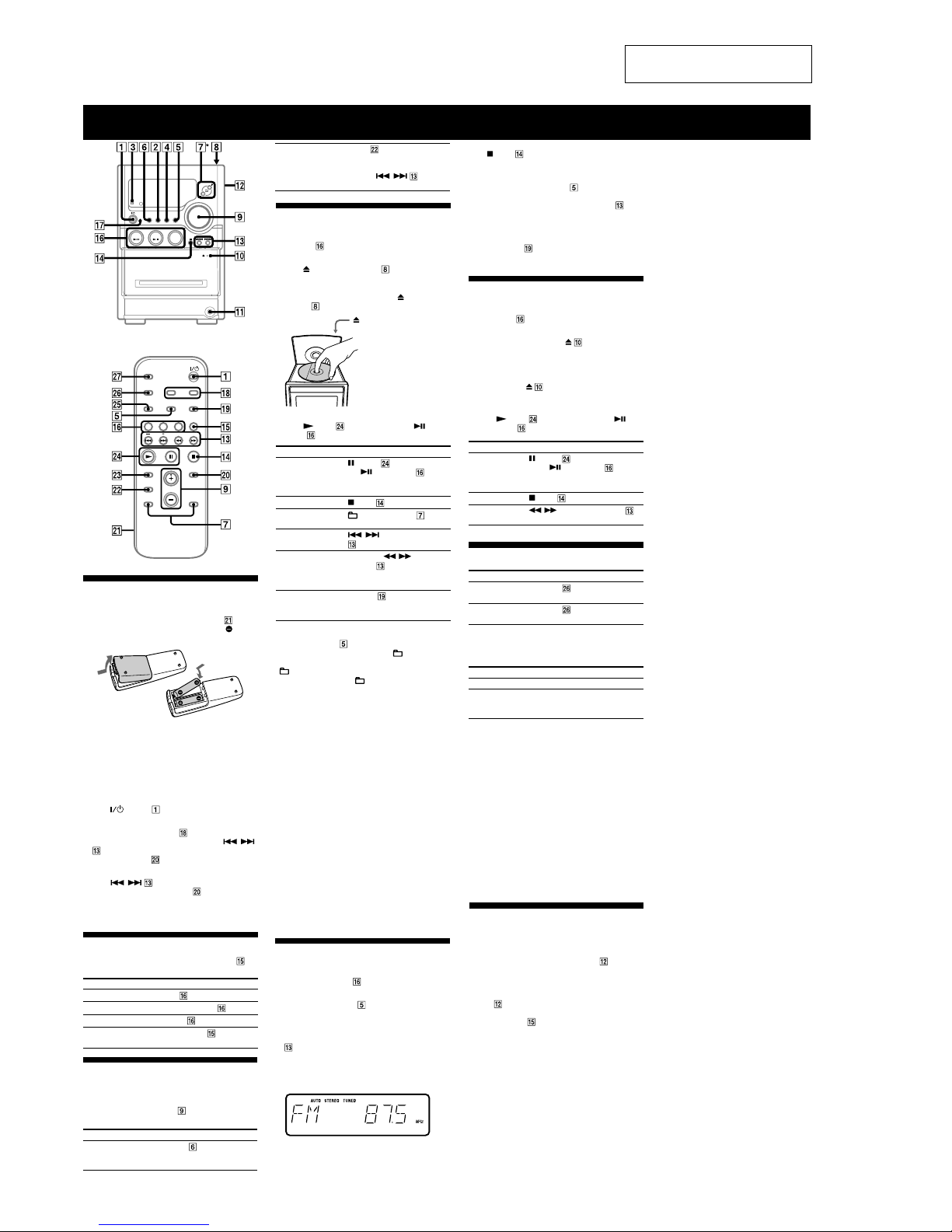
Basic Operations
Before using the system
To use the remote
Slide and remove the battery compartment lid , and
insert the two supplied R6 (size AA) batteries,
side
first, matching the polarities shown below.
Notes on using the remote
• With normal use, the batteries should last for about six months.
• Do not mix an old battery with a new one or mix different types of
batteries.
• If you do not use the remote for a long period of time, remove the
batteries to avoid damage from battery leakage and corrosion.
To set the clock
1
Turn on the system.
Press
(power) .
2
Select the clock set mode.
Press CLOCK/TIMER SET
on the remote. If the
current mode appears on the display, press
/
on the remote repeatedly to select “CLOCK” and
then press ENTER
on the remote.
3
Set the time.
Press
/ on the remote repeatedly to set
the hour, and then press ENTER
on the remote.
Use the same procedure to set the minute.
The clock settings are lost when you disconnect the
power cord or if a power failure occurs.
Playing a CD/MP3 disc
1
Select the CD function.
Press CD
on the remote.
2
Place a disc.
Press
PUSH OPEN/CLOSE on the unit,
and place a disc with the label side up on the CD
compartment.
To close the CD compartment, press
PUSH OPEN/
CLOSE
on the unit.
PUSH OPEN/CLOSE
3
Start playback.
Press
(play) on the remote (or CD/ (play/
pause)
on the unit).
To Pr ess
Pause playback
(pause) on the remote (or
CD/
(play/pause) on the
unit). To resume play, press the
button again.
Stop playback
(stop) .
Select a folder on an
MP3 disc
+/– (select folder) .
Select a track or file
/ (go back/go forward)
.
Find a point in a
track or file
Hold down
/ (rewind/fast
forward)
during playback,
and release the button at the
desired point.
Select Repeat Play
REPEAT
on the remote
repeatedly until “REPEAT” or
“REPEAT 1” appears.
To change the play mode
Press PLAY MODE repeatedly while the player is
stopped. You can select normal play (“
” for all MP3
files in the folder on the disc), shuffle play (“SHUF” or
“
SHUF*”), or program play (“PGM”).
* When playing a CD-DA disc, (SHUF) Play performs the same
operation as normal (SHUF) Play.
Notes on Repeat Play
• All tracks or files on a disc are played repeatedly up to five times.
• “REPEAT 1” indicates that a single track or file is repeated until you
stop it.
Notes on playing MP3 discs
• Do not save other types of files or unnecessary folders on a disc that
has MP3 files.
• Folders that have no MP3 files are skipped.
• MP3 files are played back in the order that they are recorded onto
the disc.
• The system can only play MP3 files that have a file extension of
“.MP3.”
• If there are files on the disc that have the “.MP3” file extension,
but that are not MP3 files, the unit may produce noise or may
malfunction.
• The maximum number of:
– folders is 150 (including the root folder).
– MP3 files is 255.
–
MP3 files and folders that can be contained on a single disc is 256.
– folder levels (the tree structure of files) is 8.
• Compatibility with all MP3 encoding/writing software, recording
device, and recording media cannot be guaranteed. Incompatible
MP3 discs may produce noise or interrupted audio or may not play
at all.
To stop automatic scanning
Press (stop) .
To tune in a station with a weak signal
If “TUNED” does not appear and the scanning does
not stop, press TUNING MODE
repeatedly until
“AUTO” and “PRESET” disappear, and then press
+/– on the remote (or TUNING +/– on the unit)
repeatedly to tune in the desired station.
To reduce static noise on a weak FM stereo
station
Press FM MODE on the remote repeatedly until
“STEREO” disappears to turn off stereo reception.
Playing a tape
1
Select the tape function.
Press TAPE
on the remote.
2
Insert a tape.
Press PUSH OPEN/CLOSE
on the unit, and
insert the TYPE I (normal) tape into the cassette
holder with the side you want to play facing forward.
Make sure there is no slack in the tape to avoid
damaging the tape or the tape deck. Press PUSH
OPEN/CLOSE
on the unit again to close the
cassette holder.
3
Start playback.
Press
(play) on the remote (or TAPE/
(play/pause)
on the unit).
To P ress
Pause playback
(pause) on the remote (or
TAPE/
(play/pause) on the
unit). To resume play, press the
button again.
Stop playback
(stop) .
Rewind or fast
forward
/ (rewind/fast forward) .
Changing the display
To c hange Press
Information on
the display*
DISPLAY
on the remote
repeatedly when the system is on.
Display mode
(See below.)
DISPLAY
on the remote
repeatedly when the system is off.
* For example, you can view CD/MP3 disc information, such as the
track or file number or folder name during normal play, or the total
play time while the player is stopped.
The system offers the following display modes.
Display mode When the system is off,
1)
Clock The clock is displayed.
Power Saving
Mode
2)
The display is turned off to conserve
power. The timer and clock continue
to operate.
1)
The STANDBY indicator lights up when the system is off.
2)
When the system is in Power Saving Mode, the following functions
are unavailable:
– setting the clock.
– changing the AM tuning interval
– changing the CD power manage function
Notes on the display information
• The following are not displayed;
– total playing time for a CD-DA disc depending on the play mode.
– total playing time for an MP3 disc.
– remaining playing time for an MP3 file.
• The following are not displayed correctly;
– elapsed playing time of an MP3 file encoded using a VBR
(variable bit rate).
– folder and file names that do not follow either the ISO9660 Level
1, Level 2 or Joliet in the expansion format.
• The following are displayed;
– ID3 tag information for MP3 files when ID3 version 1 and version
2 tags are used.
– up to 30 characters of ID3 tag information using uppercase letters
(A to Z), numbers (0 to 9), and symbols (" $ % ’ ( ) * + , – . / < =
> @ [ \ ] _ ` { | }).
* Except for the North American model
Selecting a music source
Press the following buttons (or press FUNCTION
repeatedly).
To select Press
CD CD on the remote.
Tuner TUNER/BAND
.
Tape TAPE
on the remote.
Component (connected
using an audio cord)
FUNCTION
repeatedly
until “AUDIO IN” appears.
Adjusting the sound
To adjust the volume
Press VOLUME +/– on the remote (or turn the
VOLUME control on the unit)
.
Notes on playing multisession discs
• If the disc begins with a CD-DA (or MP3) session, it is recognized
as a CD-DA (or MP3) disc, and playback continues until another
session is encountered.
• A disc with a mixed CD format is recognized as a CD-DA (audio)
disc.
Listening to the radio
1
Select “FM” or “AM.”
Press TUNER/BAND
repeatedly.
2
Select the tuning mode.
Press TUNING MODE
repeatedly until “AUTO”
appears.
To add a sound effect
To Pr ess
Generate a more dynamic
sound (Dynamic Sound
Generator X-tra)
DSGX
on the unit.
3
Tune in the desired station.
Press +/– on the remote (or TUNING +/– on the unit)
. Scanning stops automatically when a station is
tuned in, and then “TUNED” and “STEREO” (for
stereo programs) appear. When you tune in a station
that provides RDS services, the station name appears
on the display (European model only).
Using optional audio
components
To connect an optional headphones
Connect headphones to the PHONES jack on the
unit.
To connect an optional component
Connect additional audio component to the AUDIO
IN jack
on the unit using an audio analog cord (not
supplied). Turn down the volume on the system, and then
press FUNCTION
repeatedly to select the AUDIO IN
function.
Set the sound effect
EQ
on the remote
repeatedly to select “BASS”
or “TREBLE,” and then
press
/
repeatedly to adjust the level.
Ver. 1.1
SECTION 2
GENERAL
This section is extracted from
instruction manual.
6
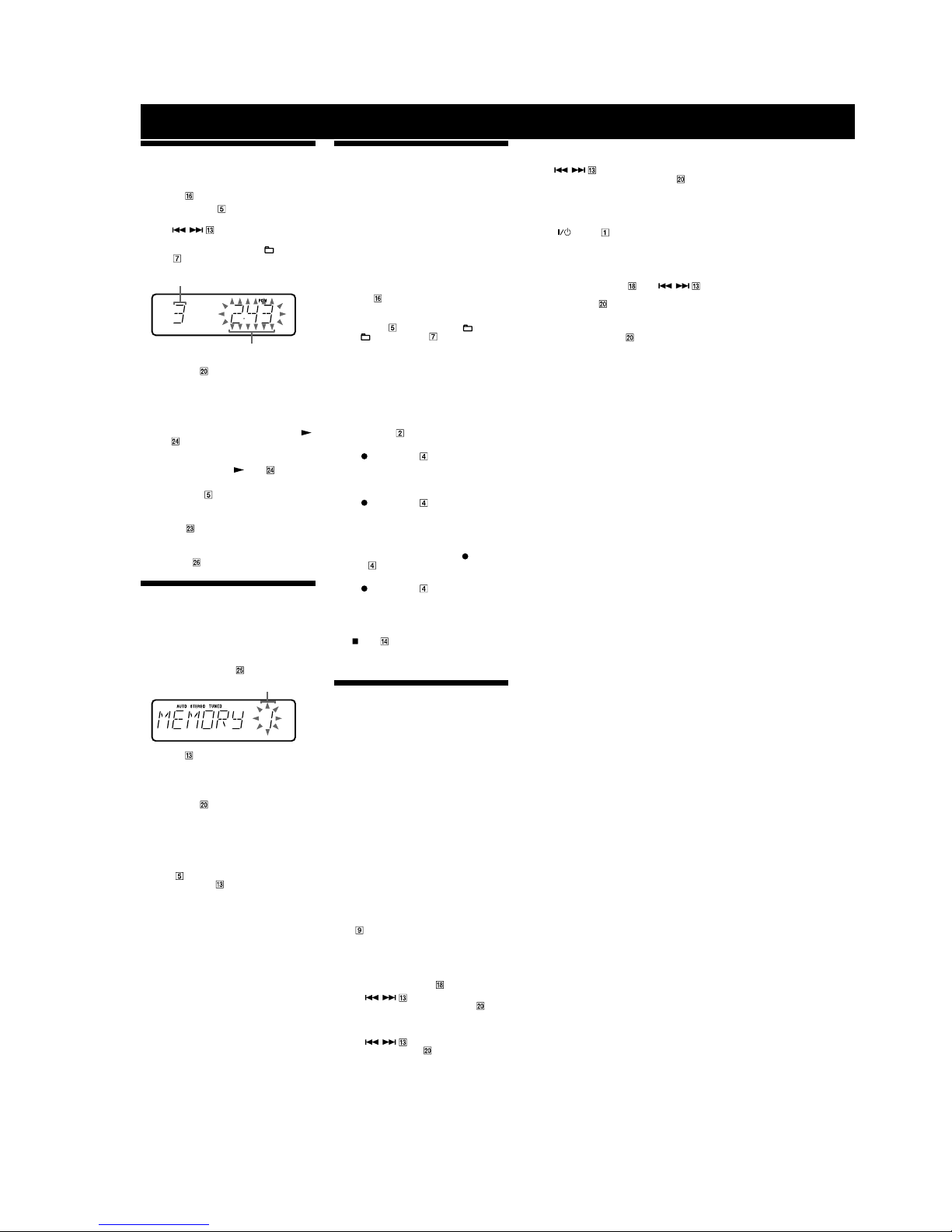
Other Operations
Creating your own CD program
(Program Play)
Use buttons on the remote to create your own program.
1
Press CD to select the CD function.
2
Press PLAY MODE repeatedly until “PGM”
appears while the player is stopped.
3
Press / repeatedly until the desired
track number appears.
When programming MP3 files, press
+/– (select
folder)
repeatedly to select the desired folder, and
then select the desired file.
Selected track or file number
Total playing time of program
(including selected track or file)
4
Press ENTER to add the track or file to the
program.
“– –.– –” appears when the total time exceeds 100
minutes for a CD, or when you select an MP3 file.
5
Repeat steps 3 through 4 to program additional
tracks or files, up to a total of 25 tracks or files.
6
To p la y your program of tracks or files, press
(play)
.
The program remains available until you open the CD
compartment. To play the same program again, select
the CD function, and press
(play) .
To cancel Program Play
Press PLAY MODE repeatedly until both “PGM” and
“SHUF” disappear while the player is stopped.
To delete the last track or file of the program
Press CLEAR while the player is stopped.
To v iew p rogram information, such as total
track number of the program
Press DISPLAY repeatedly.
Presetting radio stations
You can preset your favorite radio stations and tune
them in instantly by selecting the corresponding preset
number.
Use buttons on the remote to preset stations.
1
Tune in the desired station (see “Listening to the
radio”).
2
Press TUNER MEMORY .
Preset number
3
Press +/– repeatedly to select your desired
preset number.
If another station is already assigned to the selected
preset number, the station is replaced by the new
stations.
4
Press ENTER .
5
Repeat steps 1 through 4 to store other stations.
You can preset up to 20 FM and 10 AM stations. The
preset stations are retained for about half a day even
if you disconnect the power cord or if a power failure
occurs.
6
To call up a preset radio station, press TUNING
MODE
repeatedly until “PRESET” appears,
and then press +/–
repeatedly to select the
desired preset number.
Recording onto a tape
You can record on a TYPE I (normal) tape in two ways:
CD Synchro Recording:
You can record an entire CD onto a tape.
Manual Recording:
You can record just the portions you like from a sound
source, including connected audio components.
Use buttons on the unit to control tape recording.
1
Load a recordable tape with the side you want to
record facing forward.
2
Prepare the recording source.
For CD Synchro Recording:
Press CD
on the remote to select the CD function.
Load the disc you want to record.
When recording a folder from an MP3 disc, press
PLAY MODE
repeatedly to select “ ” and then
press
+/– (select folder) repeatedly to select
the desired folder.
To record only your favorite CD tracks in your desired
order, perform steps 2 through 5 of “Creating your
own CD program.”
For Manual Recording:
Select the desired source to record.
3
Set the tape deck to stand by for recording.
For CD Synchro Recording:
Press CD SYNC
.
For Manual Recording:
Press
PAUSE/START .
4
Start recording.
While recording, you cannot listen to other sources.
For CD Synchro Recording:
Press
PAUSE/START . When the recording
is completed, the CD player and the tape deck stop
automatically. If you are recording onto a tape and
the tape reaches the end of the front side part-way
through a track or file, “TURN TAPE” appears. Turn
the tape over to the reverse side, re-insert it, and
“PUSH REC” appears. And then press
PAUSE/
START
.
For Manual Recording:
Press
PAUSE/START , and then start playing
the desired recording source.
If there is noise while recording from the tuner,
reposition the appropriate antenna to reduce the noise.
To s top recording
Press (stop) .
Note
Recording stops if you change to a different function.
Using the Timers
The system offers three timer functions. You cannot
activate both the Play Timer and the Rec Timer at the
same time. If you use either with the Sleep Timer, the
Sleep Timer has priority.
Sleep Timer:
You can fall asleep to music. This function works even if
the clock is not set.
Press SLEEP wj on the remote repeatedly. If you select
“AUTO,” the system automatically turns off after the
current disc or tape stops or in 100 minutes.
Do not select “AUTO” during Synchro Recording of a
tape.
Play Timer:
You can wake up to CD, tape or tuner at a preset time.
Rec Timer:
You can record a preset radio station at a specified time.
Use buttons on the remote to control the Play Timer and
the Rec Timer. Make sure you have set the clock.
1
Prepare the sound source.
For Play Timer:
Prepare the sound source, and then press VOLUME
+/–
to adjust the volume.
To start from a specific CD track or MP3 file, create
your own CD program.
For Rec Timer:
Tune in the preset radio station.
2
Press CLOCK/TIMER SET .
3
Press / repeatedly to select “PLAY
SET” or “REC SET” then press ENTER
.
“ON TIME” appears, and the hour indication flashes.
4
Set the time to start playing or recording.
Press
/ repeatedly to set the hour,
and then press ENTER
.
The minute indication flashes. Use the procedure
above to set the minute.
5
Use the same procedure as in step 4 to set the
time to stop playing or recording.
6
Select the sound source or prepare the tape.
For Play Timer:
Press
/ repeatedly until the desired
sound source appears, and then press ENTER
. The
display shows the timer settings.
For Rec Timer:
Load a recordable tape. The display shows the timer
settings.
7
Press (power) to turn off the system.
The system turns on 15 seconds before the preset
time. If the system is on at the preset time, the Play
Timer and the Rec Timer will not play or record.
To activate or check the timer again
Press CLOCK/TIMER SELECT , press /
repeatedly until “PLAY SEL” or “REC SEL” appears,
and then press ENTER
.
To cancel the timer
Repeat the same procedure as above until “OFF”
appears, and then press ENTER
.
To change the setting
Start over from step 1.
Tips
• The Play Timer setting remains as long as the setting is not canceled
manually.
• The volume is reduced to minimum during the Rec Timer.
• The Rec Timer is canceled automatically after the Rec Timer has
been activated.
HCD-NEZ30
Ver. 1.1
7
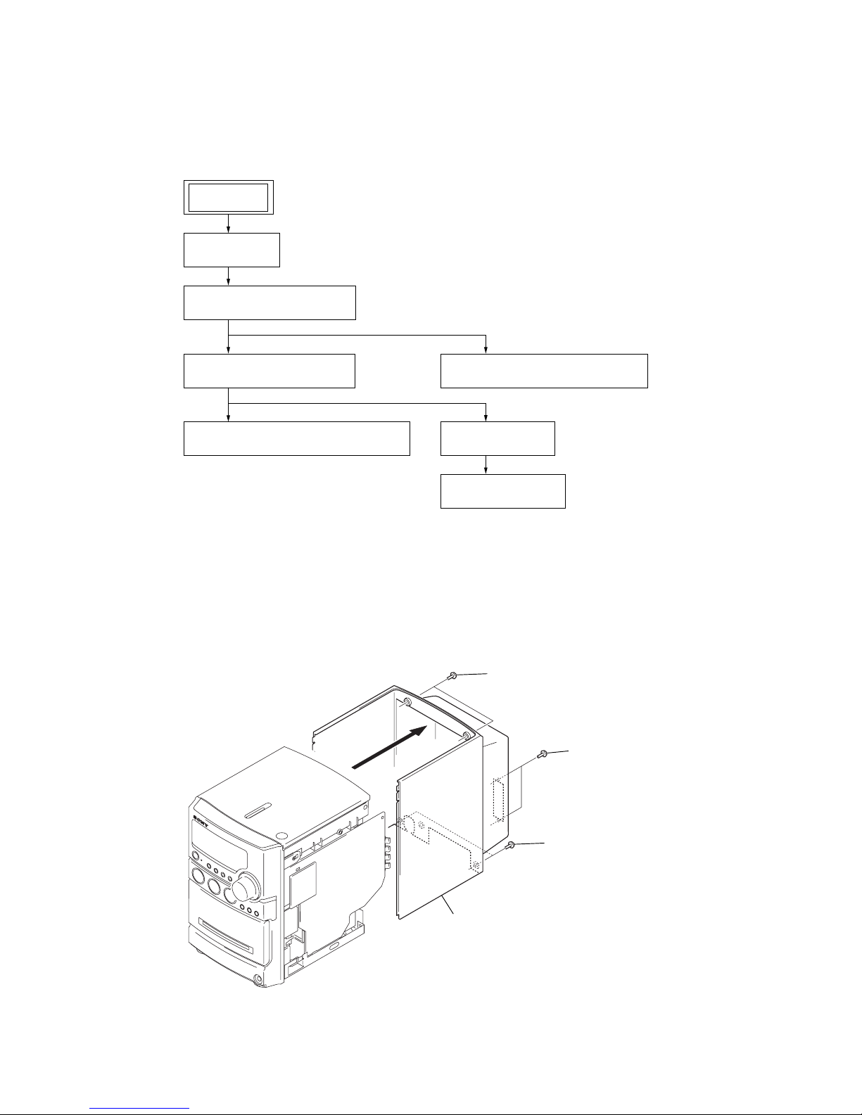
HCD-NEZ30
2
two
screws
(BVTP 3
×
10)
2
two
screws
(BVTP 3
×
8)
1
two
screws
(BVTP 3
×
10
)
3
cabinet
• This set can be disassembled in the order shown below.
3-1. DISASSEMBLY FLOW
SET
3-2. CABINET
(Page 8)
3-3. CABINET (TOP) SECTION
(Page 9)
SECTION 3
DISASSEMBLY
3-5. FRONT PANEL SECTION
(Page 10)
3-6. MECHANICAL DECK (CMAL5Z235A)
(Page 10)
Note: Follow the disassembly procedure in the numerical order given.
3-2. CABINET
3-4. BASE UNIT (BU-K8BD83S-WOD)
(Page 9)
3-7. MAIN BOARD
(Page 11)
3-8. TUNER (FM/AM)
(Page 11)
8
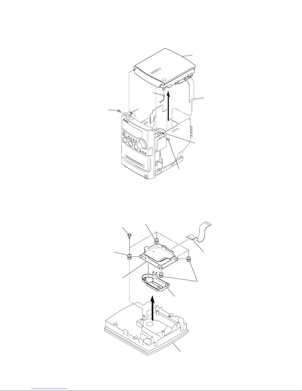
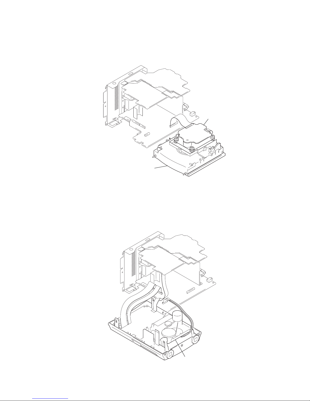
3-3. CABINET (TOP) SECTION
1
screw
(BVTP 2.6)
1
screw
(BVTP 2.6)
5
connector
(S820)
4
wire (flat type) (23 core
)
(CN317)
6
cabinet (top) section
2
claw
2
claw
3
2
four
screws
(PWH 2.6
×
10)
1
flexible flat cable (23 core)
(CN102)
6
CD cover
7
base unit
(BU-K8BD83S-WOD)
3
cabinet (top) section
4
two vibration proof rubbers (red
)
5
vibration proof rubber
(green)
5
vibration proof rubber
(green)
HCD-NEZ30
3-4. BASE UNIT (BU-K8BD83S-WOD)
9
HCD-NEZ30
2
three
screws
(BVTP 2.6)
4
harness
2
screw
(BVTP 2.6)
3
terminal lead wire
(WIRE200)
5
tape
mechanical deck
(
CMAL5Z235A
)
1
flexible flat cable (6 core
)
(FFC801)
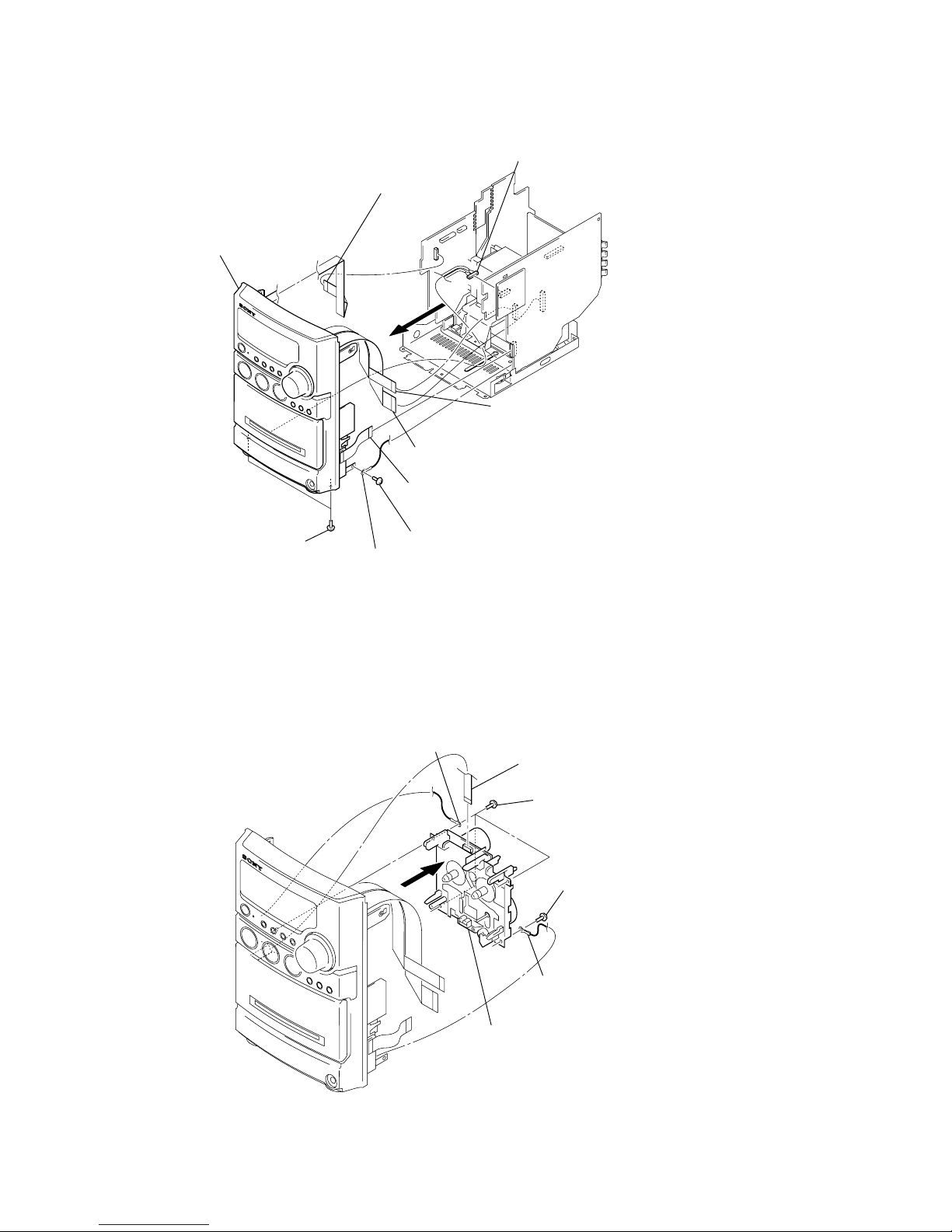
3-5. FRONT PANEL SECTION
4
9
front panel section
6
two
screws
(BVTP 3
×
flexible flat cable (9 core) (FFC803)
(CN900)
3
flexible flat cable (17 core) (FFC805)
(CN321)
1
flexible flat cable (13 core) (FFC501)
(CN500)
7
8)
8
terminal lead wire
(WIRE300)
screw
(BVTT 3
5
connector
(CN301)
2
flexible flat cable (11 core) (FFC804)
(CN320)
×
6)
3-6. MECHANICAL DECK (CMAL5Z235A)
10
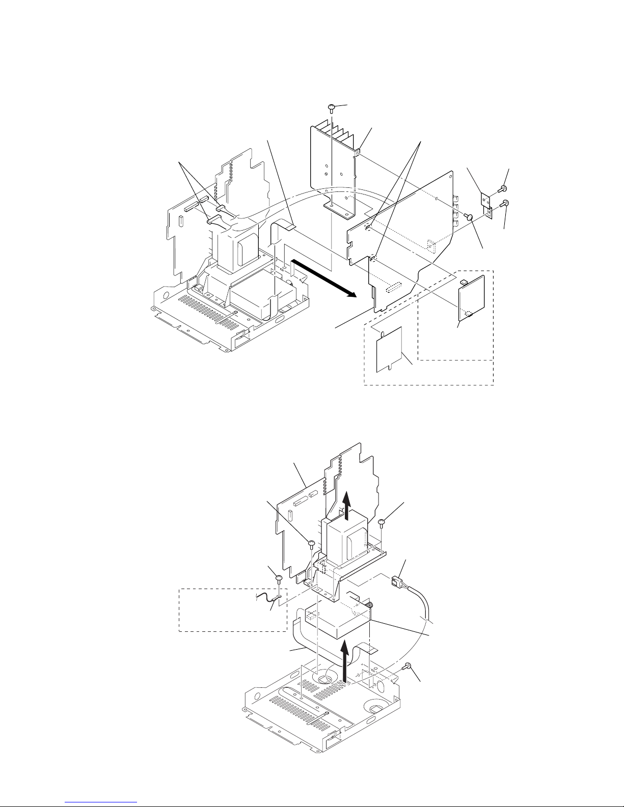
3-7. MAIN BOARD
1
two connectors
(CN902, CN903)
4
flexible flat cable
(9 core) (CN319)
2
screw (BVTT 3
×
8)
9
heat sink
6
screw
(BVTP 3
×
8)
7
screw
(BVTP 3
×
12)
8
IC bracket
5
screw
(BVTP 3
×
8)
0
Remove
two solders.
3
qs
MAIN board
qa
SHIELD board
qa
shield plate (M)
(EXCEPT UK,
East European)
(UK, East European)
2
screw
(BVTT 3
×
6)
4
three
screws
(BVTT 3
×
6)
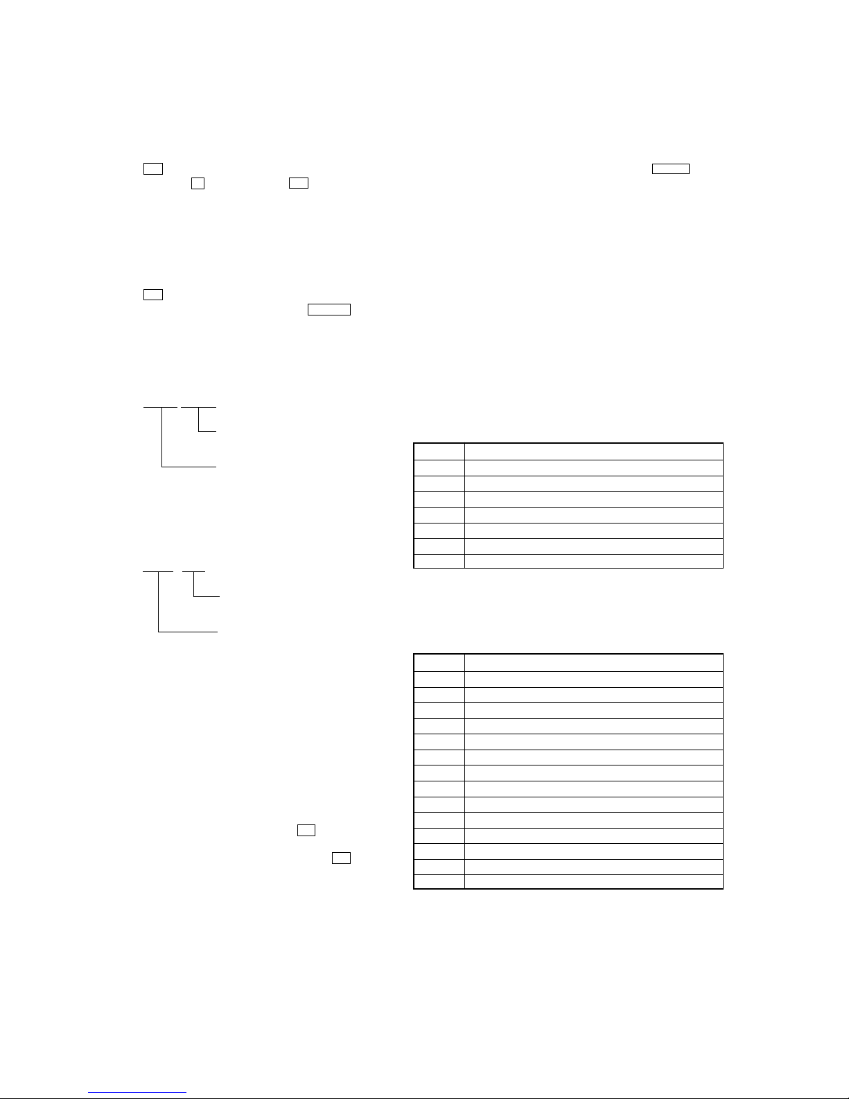
7
two
screws
(BVTP 3
×
8)
1
screw
(BVTP 3
×
8)
8
6
AC board, DC board section
5
power cord connecto
r
(CN901)
3
terminal lead wire
(WIRE900)
(US, Canadian)
0
tuner
(FM/AM)
9
flexible flat cable (9 core)
Ver. 1.5
HCD-NEZ30
3-8. TUNER (FM/AM)
11
HCD-NEZ30
distination
(In this case, North American model)
model name
(In this case, HCD-NEZXX)
Ver. 1.5
SECTION 4
TEST MODE
COLD RESET
The cold reset clears all data including preset data stored in the
RAM to initial conditions. Execute this mode when returning the
set to the customer.
Procedure:
1. Press the I/1 button to turn the power on.
2. While pressing the x button, press the I/1 button and turn
the [VOLUME] knob in the counter-clock wise.
3. The message “RESET” is displayed and the set is reset.
PANEL TEST
All segments of liquid crystal display are tested, and the version
and released date of the micro computer are displayed.
Procedure:
1. Press the I/1 button to turn the power on.
2. While pressing the [DSGX] button, press the l m button
and turn the [VOLUME] knob in the counter-clock wise.
Then all segments of liquid crystal display are turned on.
3. Press the [DSGX] button, the version and released date of the
micro computer are displayed.
example of display:
1104 V104
Version of micro computer
(In this case, version 104)
released date of micro computer
(In this case, released of November 4)
4. Press the [TUNER/BAND] button, the model name and
distination are displayed.
example of display:
6NE NA
CD ERROR HISTORY
When this mode is entered, optical pick-up error code is displayed
with the 8-character format on the fluorescent indicator tube.
Procedure:
1. Set the FUNCTION to CD.
2. While pressing the [DSGX] button, press the CD u button
and turn the [VOLUME] knob in the counter-clock wise.
3. CD error history is displayed on the liquid crystal display.
The first digit from the left indicates:
The first digit from the left indicates which mode the error history
is. In the optical pick-up error code mode, “D” is displayed on the
liquid crystal display.
The second digit from the left indicates:
(Error history No. display)
The second digit from the left indicates which order the error history
is. “1” indicates the latest error history, and each time the number
increases by one, the error history goes back to one-previous error.
The third and 4th digit from the left indicates:
(Error status display)
The third and 4th digit from the left indicates which error status is
indicated.
Display Status
01 Not focused (TOC read without a disc)
02 GFS NG (TOC read with a disc chucked)
03 Start operation time-over
04 Defocused continuously (Defocused during TOC reading)
05 Q code not entered for specified time
06 Tracking not turned ON
07 Blank disc (Blank disc TOC read)
5. Press the [PLAY MODE/TUNING MODE] button, “KEY 0 0” is
displayed on the liquid crystal display, and key test mode in.
Each time a key is pressed, the numerical value corresponding
to each key is displayed on the liquid crystal display.
6. To exit from this mode, perform the “COLD RESET”.
TUNER STEP CHANGE-OVER (Except UK and East
European models)
Either the 9 kHz step or 10 kHz step can be selected for the AM
channel step.
Procedure:
1. Set the FUNCTION to AM, and press the I/1 button to turn
the power off.
2. While depressing the [TUNER/BAND] button, press the I/1 button.
3. The message “9K STEP” or “10K STEP” is displayed on the
liquid crystal display, and thus the channel step is changed
over.
The 5th and 6th digit from the left indicates:
(Error step display)
The 5th and 6th digit from the left indicates which processing when
a trouble occurred
Display Contents
01 Power OFF in progress
02 Power ON in progress
03 Initialize in progress
04 Oscillation stopping
05 From oscillation stop, oscillation starting
06 Stopping
07 Stop operation is under way
08 Start operation in progress
09 TOC read in progress
0A Search operation is under way
0B Playback operation is under way
0C Pause operation is under way
0D Playback manual search operation is under way
0E Pause manual search operation is under way
The 7th and 8th digit from the left indicates:
The 7th and 8th digit from the left indicates which operation in
progress when a trouble occurred. (Step of each processing of the
5th and 6th digits is indicated)
12
HCD-NEZ30
SECTION 5
MECHANICAL ADJUSTMENTS
CD POWER MANEGE
This mode is for switch the CD power supply on/off. Even if this
state pulls out AC plug, it is held.
Procedure:
1. Press the I/1 button to turn the power on.
2. Set the FUNCTION to CD.
3. Press the I/1 button again to turn the power off (standby).
4. While pressing the CD u button, press the I/1 button.
5. If turns power on and display “CD POWER”, then display
“ON” or “OFF”.
• Precaution
1. Clean the following parts with a denatured-alcohol-moistened
swab :
record/playback head pinch roller
erase head rubber belts
capstan idlers
2. Demagnetize the record/playback head with a head
demagnetizer. (Do not bring the head magnetizer close to the
erase head.)
3. Do not use a magnetized screwdriver for the adjustments.
4. After the adjustments, appiy suitable locking compound to
the parts adjusted.
5. The adjustments should be performed with the rated power
supply voltage unless otherwise noted.
• Torque Measurement
Mode Torque Meter Meter Reading
2.95 – 6.86 mN⋅m
FWD CQ-102C (30 – 70 g⋅cm)
(0.42 – 0.97 oz⋅inch)
FWD
Back Tension
FF CQ-201B (more than 60 g⋅cm)
REW CQ-201B (more than 60 g⋅cm)
CQ-102C (1.5 – 5.5 g⋅cm)
0.15 – 5.39 mN⋅m
(0.021 – 0.076 oz⋅inch)
more than 5.89 mN⋅m
(more than 0.83 oz⋅inch)
more than 5.89 mN⋅m
(more than 0.83 oz⋅inch)
• Tape Tension Measurement
Mode Tension Meter Meter Reading
FWD CQ-403A
more than 100 g
(more than 3.53 oz)
13
HCD-NEZ30
set
HEAD PHONE board
PHONES jack
(J500)
+
–
level mete
r
test tape
P-4-A063
(6.3 kHz, –10 dB)
set
test tape
P-4-A063
(6.3 kHz, –10 dB)
oscilloscope
V
H
waveform of oscilloscope
in phase 45° 90° 135° 180°
good
wrong
HEAD PHONE board
PHONES jack
(J500)
Screw
position
L-CH
peak
within
1dB
Output
level
L-CH
peak
R-CH
peak
within
1dB
Screw
position
R-CH
peak
SECTION 6
ELECTRICAL ADJUSTMENTS
0 dB=0.775 VDECK SECTION
1. Demagnetize the record/playback head with a head
demagnetizer.
2. Do not use a magnetized screwdriver for the adjustments.
• Test Tape
Tape Signal Used for
P-4-A063 6.3 kHz, -10 dB Azimuth Adjustment
RECORD/PLAYBACK HEAD AZIMUTH ADJUSTMENT
Note: Remove the cassette lid assy before this adjustment.
2. Turn the adjustment screw and check output peaks. If the peaks
do not match for L-CH and R-CH, turn the adjustment screw
so that outputs match within 1dB of peak.
3. Mode: Playback
Procedure:
1. Mode: Playback
4. After the adjustments, apply suitable locking compound to
the pats adjusted.
Adjustment Location: Record/Playback/Erase Head
14
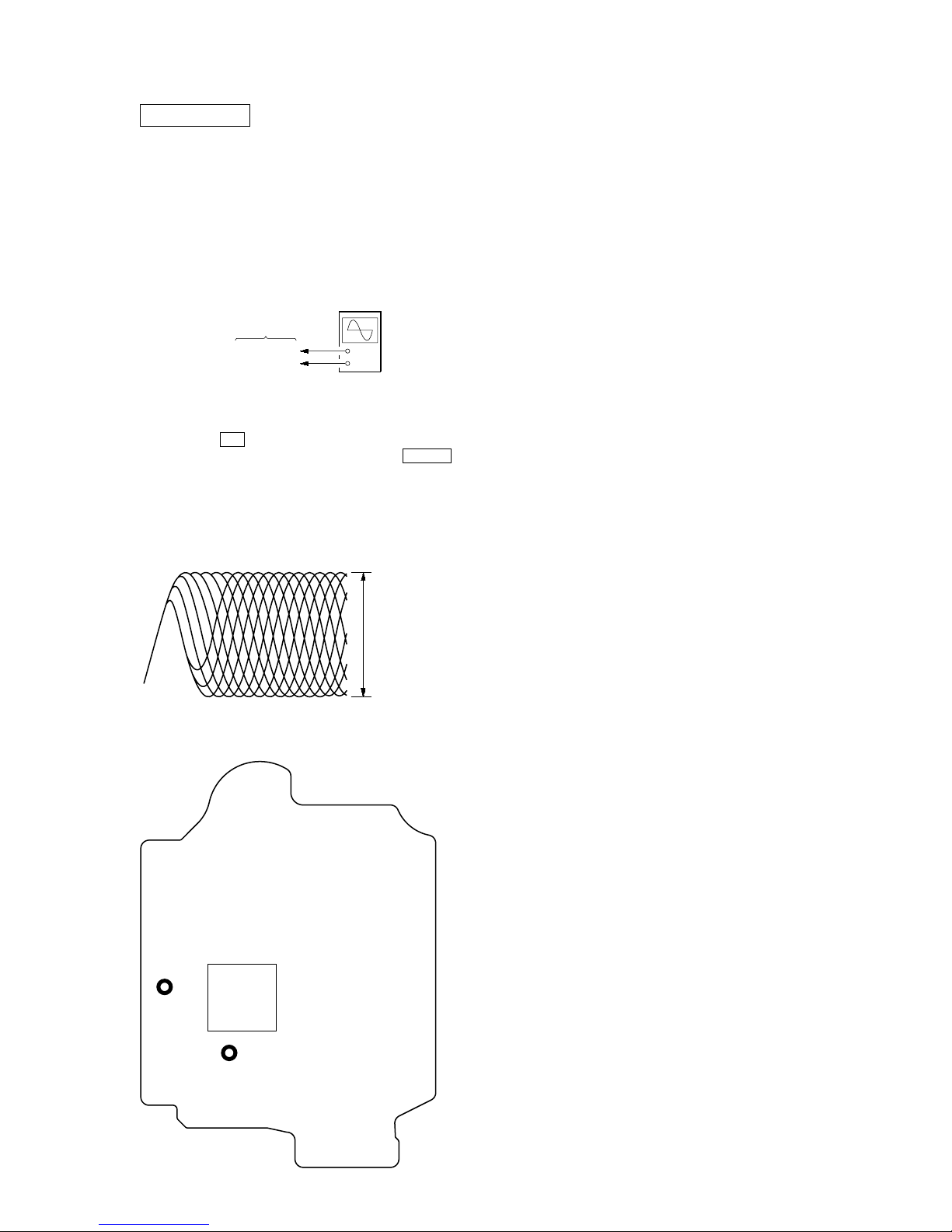
CD SECTION
CD board
TP (RFACI)
TP (VC)
oscilloscop
e
(DC range)
VOLT/DIV: 200 m
V
TIME/DIV: 500 ns
level:
0.9 ± 0.4 Vp-p
TP
(VC)
TP
(RFACI)
IC201
– CD Board (Conductor Side) –
Note:
1. CD Block is basically constructed to operate without adjustment.
2. Use YEDS-18 disc (3-702-101-01) unless otherwise indicated.
3. Use an oscilloscope with more than 10 MΩ impedance.
4. Clean the object lens by an applicator with neutral detergent when the
signal level is low than specified value with the following checks.
5. Check the focus bias check when optical pick-up block is replaced.
FOCUS BIAS CHECK
Procedure :
1. Connect oscilloscope to TP (RFACI) and TP (VC) on the CD
board.
2. Press the I/1 button to turn the power ON.
3. Set disc (YEDS-18) on the tray and press the CD u button
to playback.
4. Confirm that oscilloscope waveform is as shown in the figure
below. (eye pattern)
A good eye pattern means that the diamond shape (◊) in the
center of the waveform can be clearly distinguished.
+
–
HCD-NEZ30
Checking Location:
15

HCD-NEZ30
MEMO
16
 Loading...