

Sony HCDMD-313 Service manual
HCD-MD313
SERVICE MANUAL
HCD-MD313 is the amplifier, CD, MD and
tuner section in DHC-MD313.
US and foreign patents licensed from Dolby
Laboratories Licensing Corporation.
Amplifier section
Canadian model:
Continuous RMS power output
20+20 watts
(6 ohms at 1 kHz, 1%
THD, 120 V) (Rated)
25+25 watts
(6 ohms at 1 kHz, 10%
THD, 120 V) (Refer-
ence)
European model:
DIN power output (Rated)
25 + 25 watts (6 ohms
at 1 kHz, DIN, 230 V)
Continuous RMS power output (Reference)
30+30 watts
(6 ohms at 1 kHz, 10%
THD, 230 V)
Music power output (Reference)
50+50 watts
Other models:
DIN power output (Rated)
20+20 watts
(6 ohms at 1 kHz, DIN,
240 V)
18+18 watts
(6 ohms at 1 kHz, DIN,
220 V)
Continuous RMS power output (Reference)
25+25 watts (6 ohms at
1 kHz, 10% THD,
240 V)
23+23 watts
(6 ohms at 1 kHz, 10%
THD, 220 V)
Peak music power output 400 watts
Inputs TAPE IN (phono
Outputs TAPE OUT (phono
PHONES (Stereo minijack):
SPEAKER: accepts impedance of
CD player section
System Compact disc and digi-
Laser Semiconductor laser
Laser output Max. 44.6 µW*
CD
Section
MD
Section
SPECIFICATIONS
jacks):
voltage 250 mV/125
mV, impedance 47
kilohms
jacks):
voltage 250 mV impedance 1 kilohms
accepts headphones of
8 ohms or more.
6 to 16 ohms.
tal audio system
(λ = 780 nm)
Emission duration:
continuous
*This output is the
value measured at a
distance of 200 mm
from the objective lens
MINI Hi-Fi COMPONENT SYSTEM
Canadian Model
AEP Model
UK Model
E Model
Model Name Using Similar Mechanism HCD-T1
CD Mechanism Type
Base Unit Name BU-5BD19
Optical Pick-up Name KSS-213B/K-N
Model Name Using Similar Mechanism MDS-MX1
MD Mechanism Type MDM-3D
Optical Pick-up Name KMS-260A/J1N
Frequency response 2 Hz – 20 kHz
MD deck section
System MiniDisc digital audio
Laser Semiconductor laser
Laser output Max. 44.6 µW*
Recording time 74 minutes max. (using
Sampling frequency 44.1 kHz
Frequency response 5 Hz to 20 kHz
– Continued on next page –
CDM13C-5BD19
surface on the Optical
Pick-up Block with a 7
mm aperture.
system
(λ = 780 nm)
Emission duration:
continuous
*This output is the
value measured at a
distanceof 200 mm
from the objective lens
surface on the Optical
Pick-up Block with a 7
mm aperture.
MDW-74)
MICROFILM
Tuner section
FM stereo, FM/AM superheterodyne tuner
FM tuner section
Tuning range 87.5 – 108.0 MHz (50 kHz step)
Aerial FM lead aerial
Aerial terminals 75 ohms unbalanced
Intermediate frequency 10.7 MHz
AM tuner section
Tuning range
North American model:
AM: 530 – 1,710 kHz
(with the interval set at 10 kHz)
531 – 1,710 kHz
(with the interval set at 9 kHz)
European model:
MW: 522 – 1,611 kHz
(with the interval set at 9 kHz)
LW: 144 – 288 kHz
(with the interval set at 3 kHz)
Other models:
MW: 531–1,602 kHz
(with the interval set at 9 kHz)
530 – 1,710 kHz
(with the interval set at 10 kHz)
SW: 5.95 – 17.90 MHz
(with the interval set at 5 kHz)
General
Power requirements
North American model: 120 V AC, 60 Hz
European model: 220 – 230 V AC, 50/60 Hz
Other models: 110 – 120 V or 220 – 240 V AC, 50/60 Hz
Power consumption:
North American model: 70 watts
Other models: 80 watts
Dimensions
Amplifier/Tuner/MD/CD section:
Approx. 215 × 150 × 320 mm (81/4 × 6 × 125/8 in)
(w/h/d) incl. projecting parts and controls
Mass
Amplifier/Tuner/MD/CD section:
Approx. 5.5 kg (12 lb 8 oz.)
TABLE OF CONTENTS
SELF-DIAGNOSIS DISPLAY ......................................... 2
1. SERVICING NOTES ............................................... 3
2. GENERAL.................................................................... 5
3. DISASSEMBLY.......................................................... 8
4. TEST MODE .............................................................. 15
5. ELECTRICAL ADJUSTMENTS
MD Section...................................................................... 19
CD Section....................................................................... 24
6. DIAGRAMS
6-1. Block Diagrams
CD Section....................................................................... 27
MD Section...................................................................... 29
Main Section.................................................................... 31
6-2. Printed Wiring Board — CD Section — ......................... 33
6-3. Schematic Diagram — CD Section — ............................ 35
6-4. Printed Wiring Boards — MD Section —....................... 39
6-5. Schematic Diagram — MD Section — ........................... 41
6-6. Schematic Diagram — Main Section — ......................... 46
6-7. Printed Wiring Boards — Main Section —..................... 51
6-8. Printed Wiring Board — Audio Section — ..................... 53
6-9. Schematic Diagram — Audio Section —........................ 55
6-10. Printed Wiring Boards — Panel/Power Section —......... 58
6-11. Schematic Diagram — Panel/Power Section — ............. 61
6-12. IC Pin Function Description ............................................ 74
7. EXPLODED VIEWS ................................................ 82
Supplied accessories: Remote RM-MD313 (1)
AA (R6) batteries (2)
AM loop aerial (1)
FM lead aerial (1)
Design and specifications are subject to change without notice.
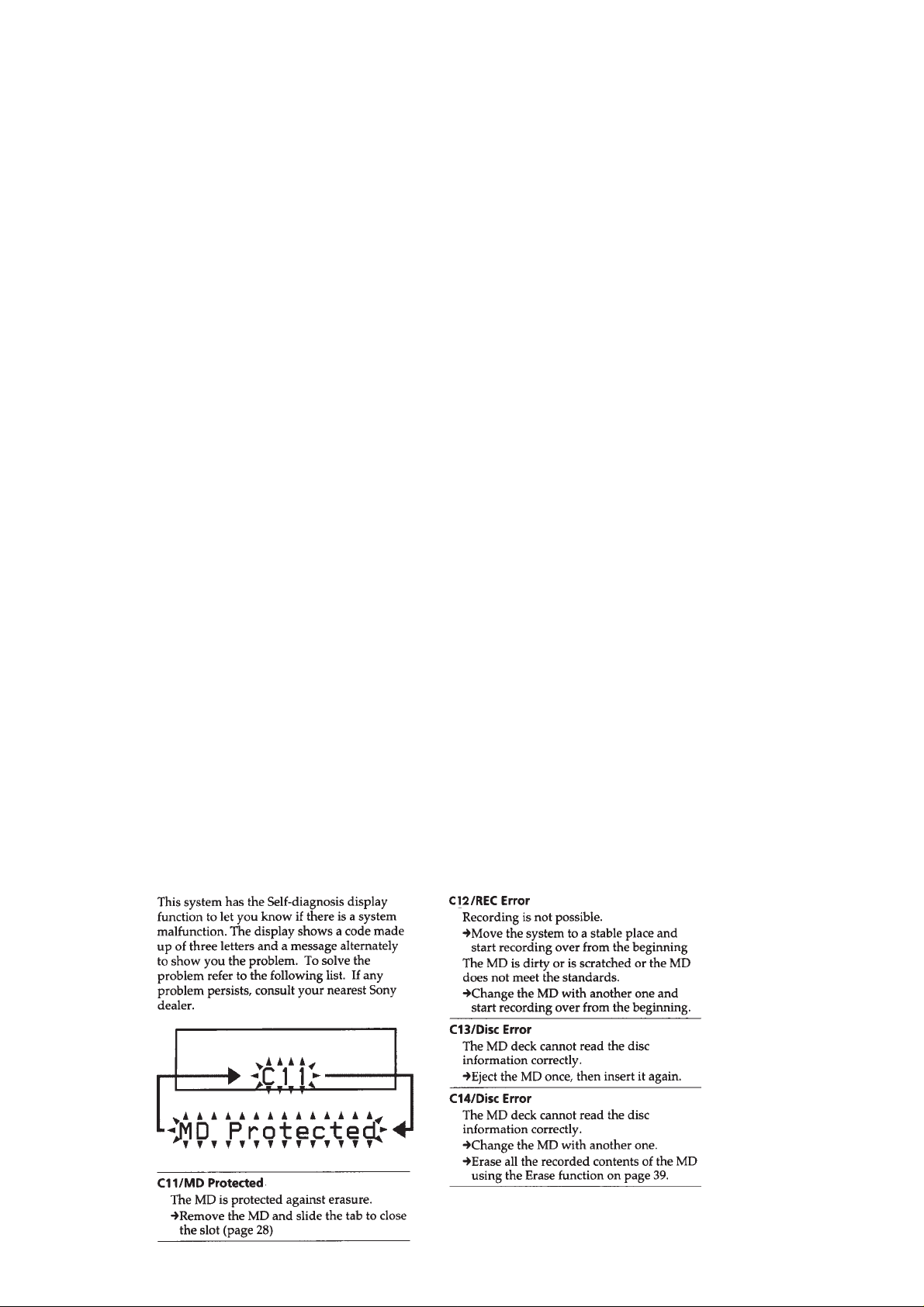
SELF-DIAGNOSIS
8. ELECTRICAL PARTS LIST ................................ 88
DISPLAY
– 2 –
SECTION 1
SERVICING NOTES
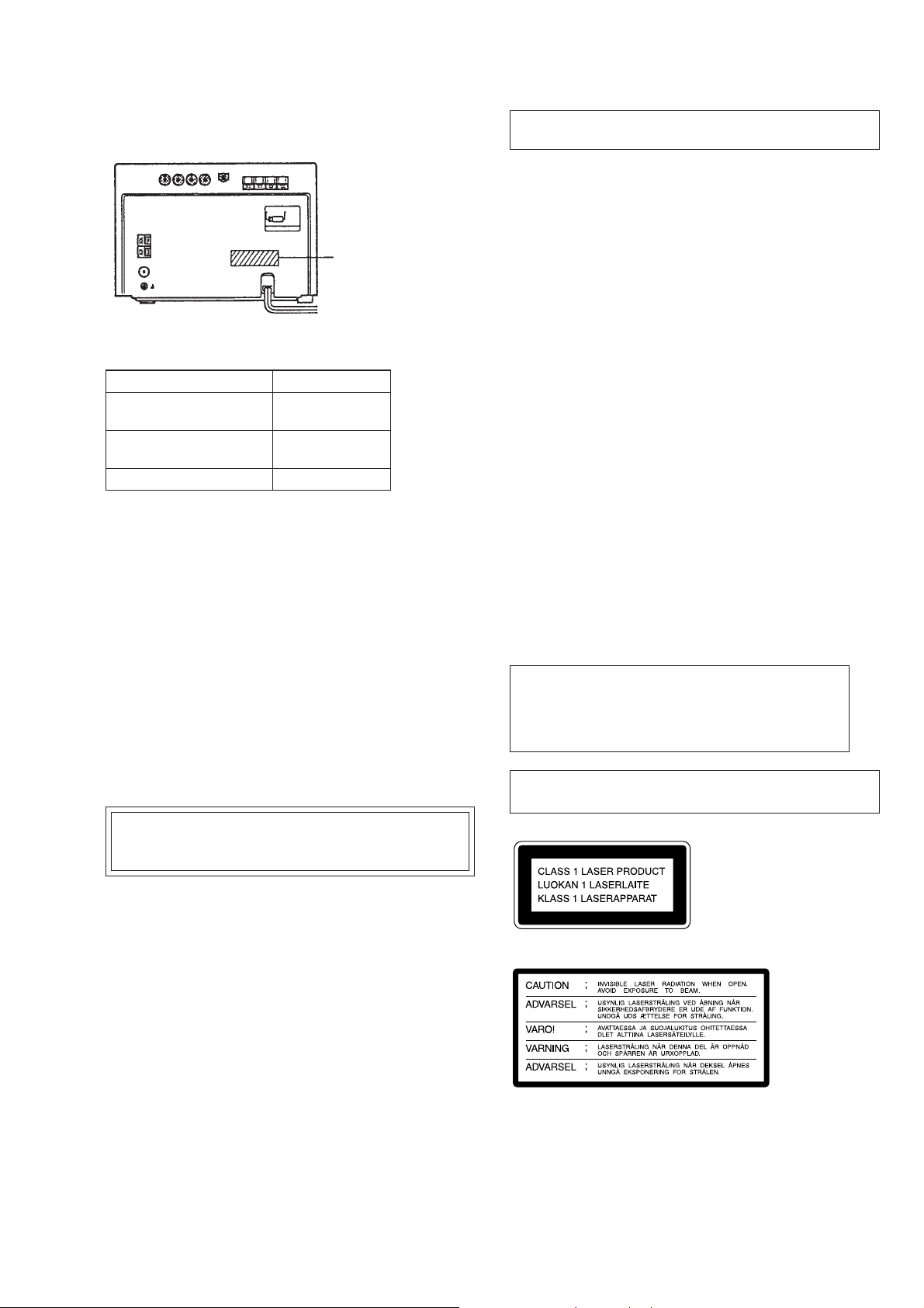
MODEL IDENTIFICATION
— BACK PANEL —
PART No.
MODEL PARTS No.
AEP, UK, German,
AED models
Hong Kong, Malaysia,
Singapore models
4-993-849-1π
4-993-849-2π
Canadian model 4-993-849-3π
• Abbreviation
AED: North European
NOTES ON HANDLING THE OPTICAL PICK-UP
BLOCK OR BASE UNIT
The laser diode in the optical pick-up block may suffer electrostatic break-down because of the potential difference generated
by the charged electrostatic load, etc. on clothing and the human
body.
During repair, pay attention to electrostatic break-down and also
use the procedure in the printed matter which is included in the
repair parts.
The flexible board is easily damaged and should be handled with
care.
NOTES ON LASER DIODE EMISSION CHECK
The laser beam on this model is concentrated so as to be focused
on the disc reflective surface by the objective lens in the optical
pick-up block. Therefore, when checking the laser diode emission, observe from more than 30 cm away from the objective lens.
Notes on chip component replacement
• Never reuse a disconnected chip component.
• Notice that the minus side of a tantalum capacitor may be dam-
aged by heat.
Flexible Circuit Board Repairing
• Keep the temperature of soldering iron around 270 ˚C during
repairing.
• Do not touch the soldering iron on the same conductor of the
circuit board (within 3 times).
• Be careful not to apply force on the conductor when soldering
or unsoldering.
Note:
Be sure to connect all wires (including FFC) in the MD
section before applying power or ICs may be damaged.
SAFETY-RELATED COMPONENT WARNING!!
COMPONENTS IDENTIFIED BY MARK ! OR DOTTED
LINE WITH MARK ! ON THE SCHEMATIC DIAGRAMS
AND IN THE PARTS LIST ARE CRITICAL TO SAFE
OPERATION. REPLACE THESE COMPONENTS WITH
SONY PARTS WHOSE PART NUMBERS APPEAR AS
SHOWN IN THIS MANUAL OR IN SUPPLEMENTS PUBLISHED BY SONY.
ATTENTION AU COMPOSANT AYANT RAPPORT
À LA SÉCURITÉ!
LES COMPOSANTS IDENTIFIÉS P AR UNE MARQUE !
SUR LES DIAGRAMMES SCHÉMATIQUES ET LA LISTE
DES PIÈCES SONT CRITIQUES POUR LA SÉCURITÉ
DE FONCTIONNEMENT. NE REMPLACER CES COMPOSANTS QUE PAR DES PIÈCES SONY DONT LES
NUMÉROS SONT DONNÉS DANS CE MANUEL OU
DANS LES SUPPLÉMENTS PUBLIÉS PAR SONY.
CAUTION
Use of controls or adjustments or performance of procedures other than those specified herein may result in hazardous radiation exposure.
Laser component in this product is capable of emitting radiation
exceding the limit for Class 1.
This appliance is classified as
a CLASS 1 LASER product.
The CLASS 1 LASER PRODUCT MARKING is located on
the rear exterior.
This caution label is located inside the unit.
– 3 –
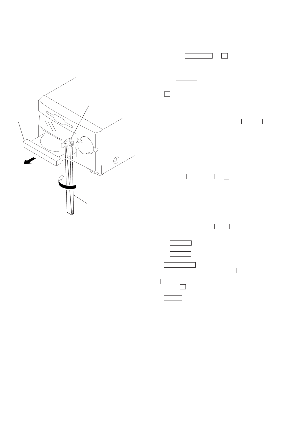
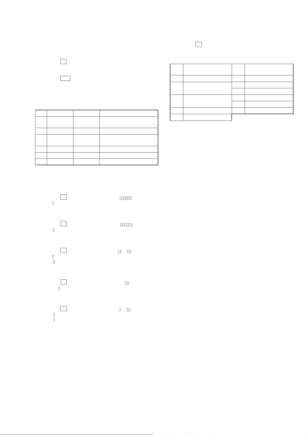
DISC TABLE GETTING OUT PROCEDURE ON
THE POWER SUPPLY IS OFF
FLUORESCENT INDICA TOR TUBE/BUTTONS/JOG/
LEDs CHECK MODE
1. Insert the tweezers to a hole on bottom of the chassis as shown
a figure, then tern fully it toward direction 2.
2. Pull out the disc table.
cam
disc table
3
2
1
tweezers
1. Press two buttons PLA Y MODE and p (MD) simultaneously
for standby status.
2. Fluorescent indicator tube and LEDs are all turned on.
Press FUNCTION button, the fluorescent indicator tube displays pattern change to cycle.
Turning the VOLUME knob, and the each LED turned on to
order.
3. Press p (CD) button, and the Key check mode.
4. The fluorescent indicator tube displays “KEY=0 JOG=0”.
Each time a button is pressed, “KEY”=value increases.
Howerer, once a button is pressed , it is no longer taken into
account.
“JOG=” value increases like 1, 2, 3... if rotating VOLUME
knob in clock width, or it decreases like 0, 9, 8... if rotating in
cunter clock width.
5. To e xit from this mode, press order all buttons (15 b uttons), the
displays “KEY=OK”, and press any button, or disconnect the
power cord.
SUB CLOCK CHECK
1. Connect an oscilloscope to IC601 pin (¡ and ground of the
MAIN board.
2. Press two buttons PLAY MODE and § (MD)
Simultaneously, and the fluorescent indicator tube displays
“32.768 kHz (91)”.
3. To check the signal on oscilloscope becomes 32 kHz square
wave.
4. Press POWER button to exit.
TA CHECK
1. Press POWER button and system power on.
2. Press two buttons PLAY MODE and p (CD)
simultaneously, the fluorescent indicator tube displays “TA
Test”.
3. Rotation VOLUME knob in clock width a little, the fluorescent indicator tube displays “Volume MAX”.
Rotation VOLUME knob in cunter clock widh a little, the fluorescent indicator tube displays “Volume MIN”.
4. Press CD-MD SYNC button, the fluorescent indicator tube
displays “BASS/TRE MAX”. Press REPEAT button, the fluorescent indicator tube displays “BASS/TRE MIN”. Press
p (MD) button, the fluorescent indicator tube displays “ ALL
FLAT”. Press p (CD) button, the fluorescent indicator tube
displays “SURROUND = ON”.
5. Press POWER button to exit, and system power off.
– 4 –
SECTION 2
GENERAL
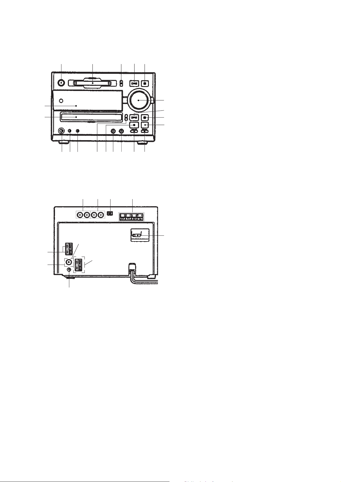
LOCATION OF CNTROLS
– Front Panel –
12345
!º
!¡
– Rear Panel –
123 4
Europian model
1 POWER button
2 MD disk slot
3 § (MD) button
4 ^ (MD) button
5 p (MD) button
6 VOLUME control knob
7 ^ (CD) button
8 p (CD) button
9 FUNCTION button
6
7
8
9
@º!ª!•!¶!§!∞!¢!£!™
5
!º Fluorescent indicator tube
!¡ CD disc tray
!™ PHONES jack
!£ PLAY MODE • TUNING MODE button
!¢ REPEAT • STEREO/MONO button
!∞ § (CD) button
!§ TUNER/BAND button
!¶ CD-MD SYNC button
!• r REC button
!ª MD/CD = 0 • TUNER – button
@º MD/CD ) + • TUNER + button
1 TAPE OUTPUT pin jack
2 TAPE INPUT pin jack
3 AU BUS jack
4 SPEAKER terminal
5 VOLTAGE SELECTOR switch
(Except European models)
6 AM ANTENNA terminal
7 FM ANTENNA terminal
8 SIGNAL GND terminal
6
7
Other models
8
– 5 –
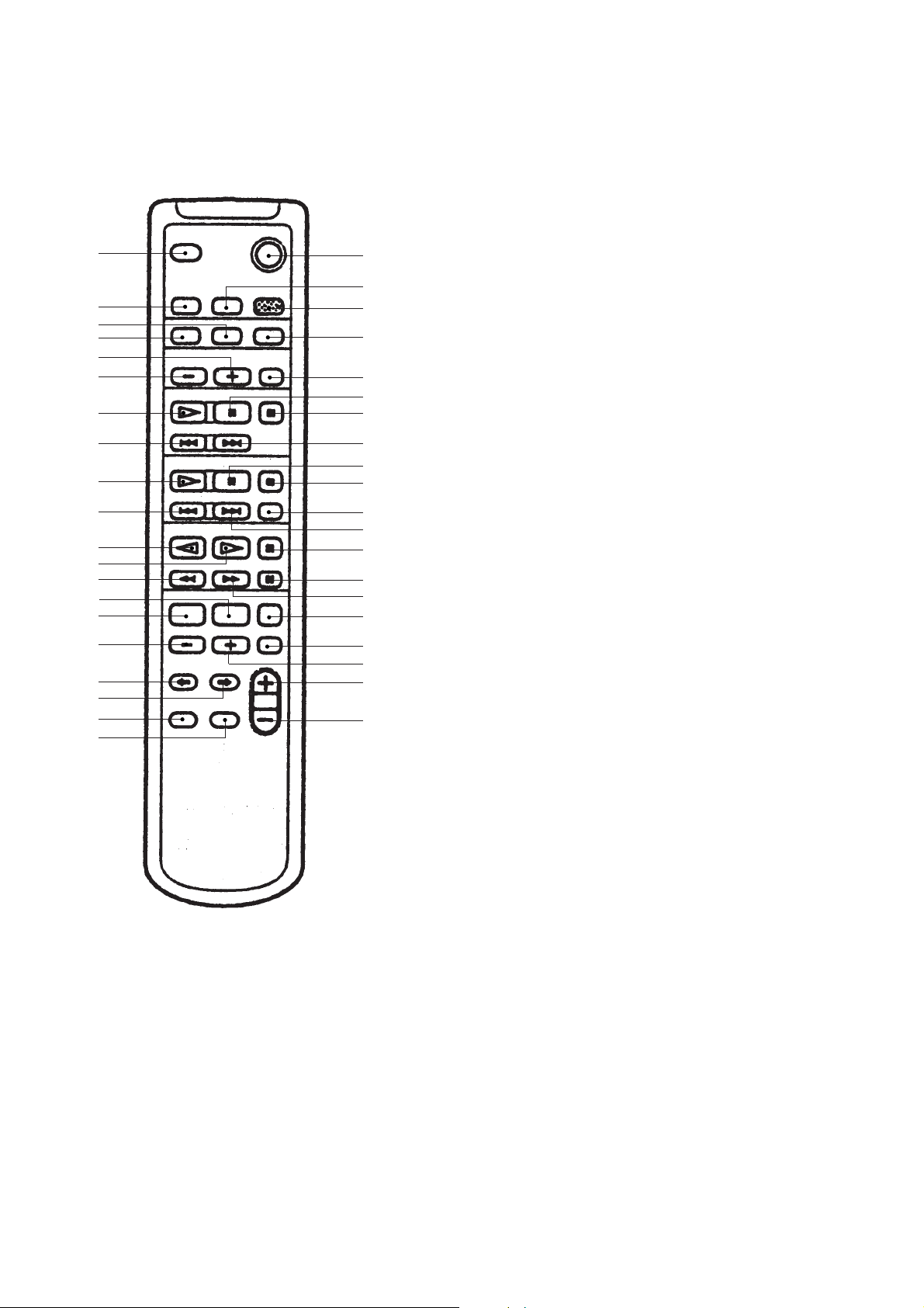
– Remote controller –
@¡
@™
@£
@¢
@∞
@§
@¶
@•
@ª
#º
#¡
#™
#£
#¢
#∞
#§
#¶
#•
#ª
$º
1
2
3
4
5
6
7
8
9
!º
!¡
!™
!£
!¢
!∞
!§
!¶
!•
!ª
@º
1 POWER button
2 DBFB button
3 MUSIC MENU button
4 SCROLL button
5 BAND button
6 MD P button
7 MD p button
8 MD + button
9 CD P button
!º CD p button
!¡ LOOP button
!™ CD + button
!£ TAPE p button
!¢ TAPE P button
!∞ TAPE ) button
!§ CLOCK/TIMER SET, button
!¶ DISPLAY button
!• + button
!ª VOL + button
@º VOL – button
@¡ SLEEP button
@™ FUNCTION button
@£ REPEAT button
@¢ PLAY MODE button
@∞ PRESET + buuton
@§ PRESET – button
@¶ MD ( button
@• MD = button
@ª CD ( button
#º CD = button
#¡ TAPE 9 button
#™ TAPE ( button
#£ TAPE 0 button
#¢ CLOCK/TIMER SELECT button
#∞ EDIT button
#§ – button
#¶ CURSOR ? button
#• CURSOR / button
#ª ENTER/YES button
$º CANCEL/NO button
– 6 –
– 7 –
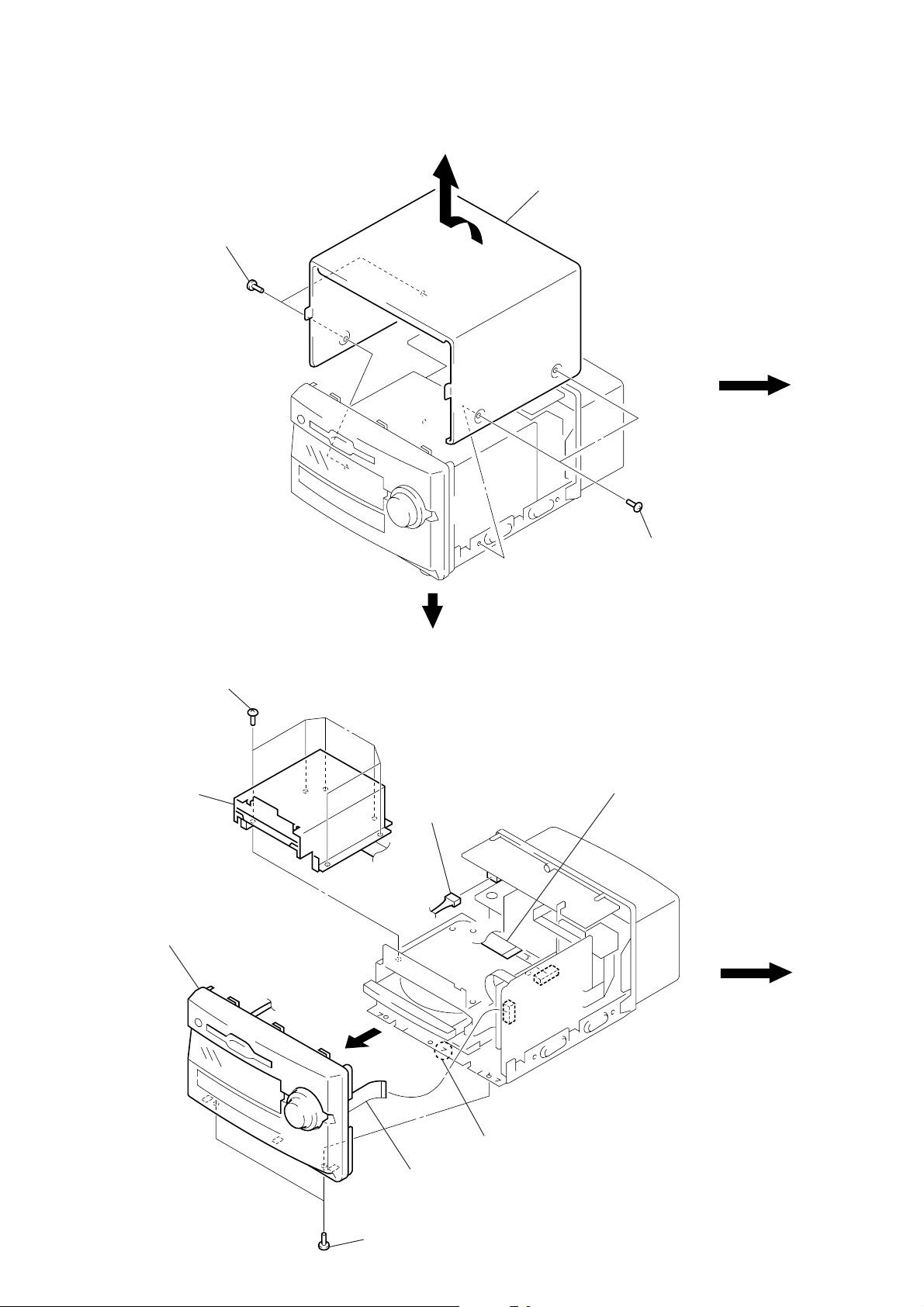
SECTION 3
DISASSEMBLY
Note: Follow the disassembly procedure in the numerical order given.
CASE
1
two screws
(case 3 TP2)
2
case
FRONT PANEL/MD MECHANISM DECK SECTION
7
six screws (BVTT 3 × 6)
8
MD mechanism section
5
front panel section
3
connector
(CN490)
1
two screws
(case 3 TP2)
6
wire (flat type) (25 core)
(CN820)
1
two screws
(BVTP 3 × 8)
4
claw
2
wire (flat type) (23 core)
(CN873)
– 8 –
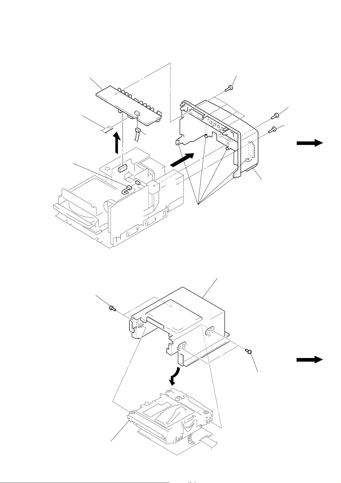
BACK PANEL, JACK BOARD
7
JACK board
6
wire (flat type) (15 core)
(CN401)
1
connector
(CN590)
8
connector
(CN402)
4
five claws
2
four screws
(BVTP 3 × 10)
5
back panel
3
screw
(BVTP 3 × 8)
2
screw
(BVTP 3 × 10)
MD MECHANISM DECK (MDM-3D)
1
two screws
(BVTT 2 × 3)
bracket (MD)
1
two screws
(BVTT 2 × 3)
2
MD mechanism deck
(MDM-3D)
– 9 –
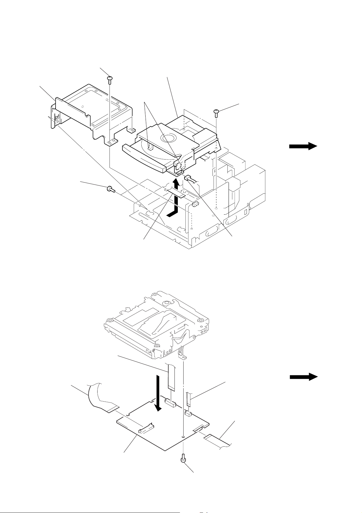
CD MECHANISM DECK (CDM13C-5BD19)
3
two screws
(BVTP 3 × 6)
4
bracket (CD)
6
3
two screws
(BVTP 3 × 6)
7
CD mechanism deck
(CDM13C-5BD19)
two hooks
5
two screws
(BVTP 3 × 8)
BD (MD) BOARD
3
5
OP relay flexib le board
(CN101)
1
wire (flat type) (19 core)
(CN801)
wire (flat type) (14 core)
(CN106)
2
connector
(CN291)
2
flexible board
(over write head)
(CN104)
6
BD (MD) board
– 10 –
4
screw
(BVTP 2 × 4)
1
wire (flat type) (25 core)
(CN107)
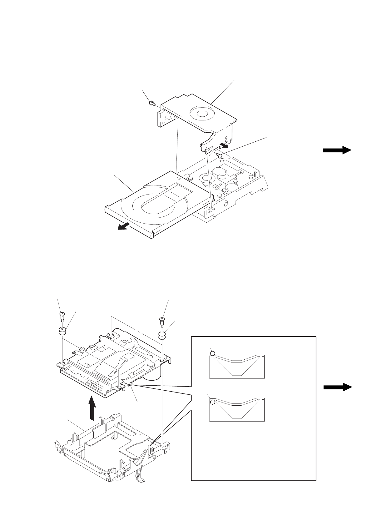
DISC TABLE
3
Pull the disc table
1
screw (BV 3 × 8)
2
holder (MG) ass'y
1
screw (BV 3 × 8)
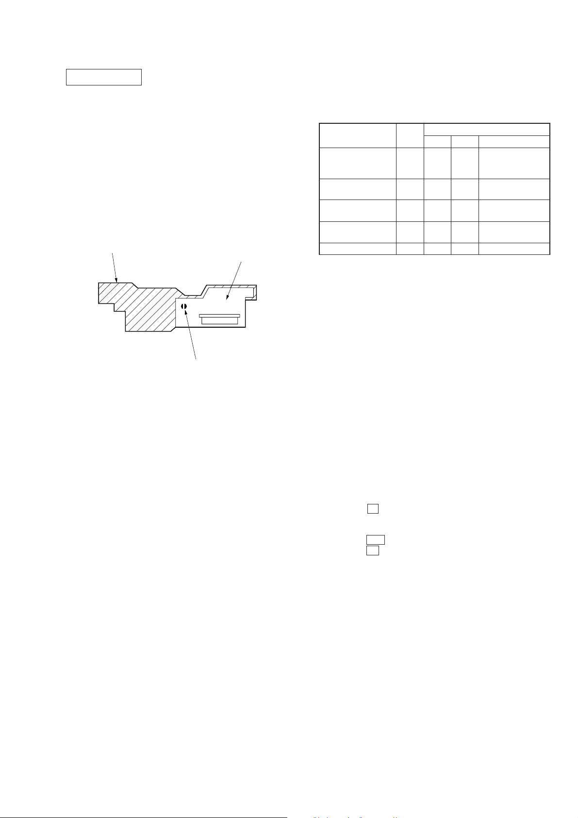
SUB CHASSIS
1
two step screws
2
3
sub chassis
two insulators
part
A
1
two step screws
2
two insulators
part
A
part
A
Take care so that the part
may be right position when installing.
NG
OK
A
– 11 –
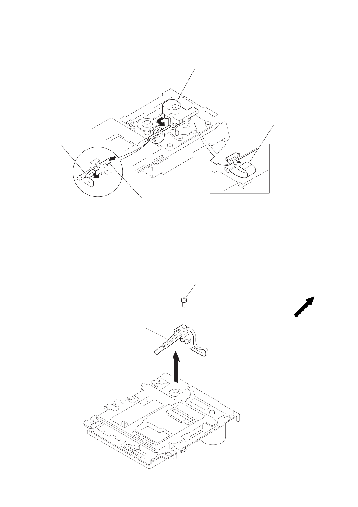
OPTICAL PICK-UP (KSS-213B/K-N)
4
Remove the optical pick-up (KSS-213B/K-N)
In the direction of the arrow C.
1
Move the claw in the
direction of the arrow A.
OVER WRITE HEAD
A
B
C
2
Remove the sled shaft in the
direction of the arrow B.
1
screw (P 1.7 × 6)
3
wire (flat type) (16 core)
(CNU101)
2
over write head
– 12 –
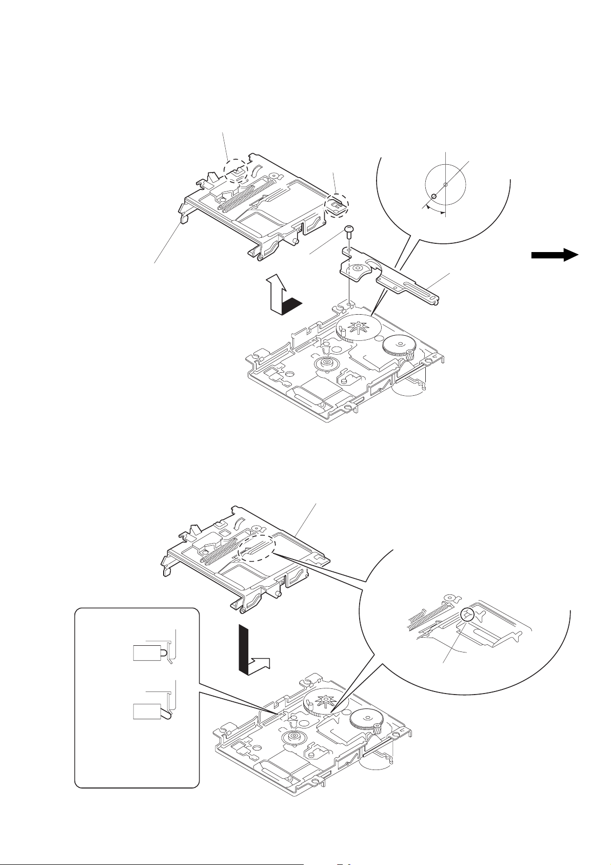
SLIDER COMPLETE ASS’Y
claw
4
Remove the slider complete ass’y
in the direction of arrow with putting
out of two claws.
1
special screw
(M 1.7 × 1.4)
claw
3
Set the shaft of gear (LB) to be at the
position in the figure.
45°
2
retainer (gear)
NOTE FOR INSTALLATION
• SLIDER COMPLETE ASS’Y
OK
NG
slider ass’y
Install the part A of lever (head up)
to pass over the slider complete ass’y.
part A
Take care not to damage
the detective switch.
– 13 –
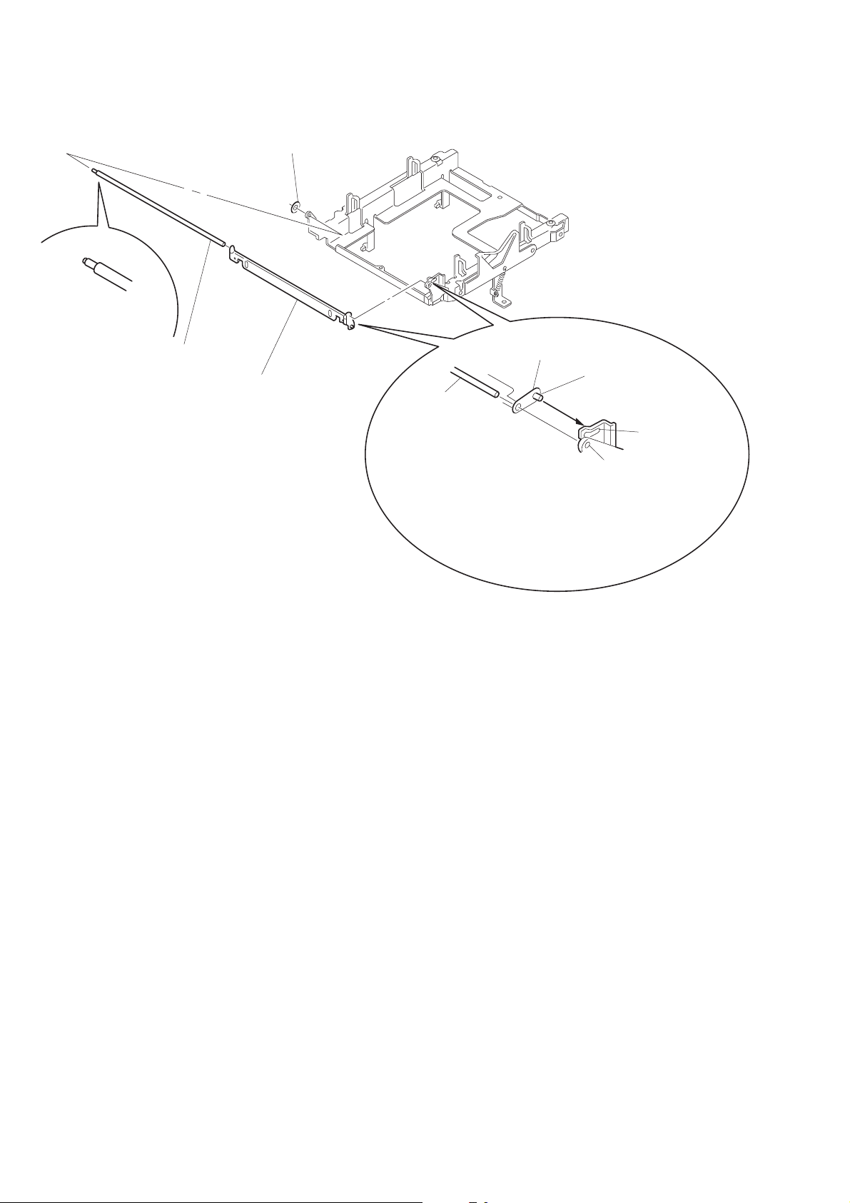
SHUTTER ASS’Y
2
shaft (shutter) A
1
stopper washer
3
shutter ass’y
shutter ass’y
shaft (shutter) B
shaft (shutter) A
hole B
hole A
When installing, install the shaft (shutter) A into
the hole as show in the figune before installing the shaft (shutter) B into the hole B.
– 14 –
SECTION 4
TEST MODE
4-1. PRECAUTIONS FOR USE OF TEST MODE
1. As loading related operations will be performed regardless of
the test mode operations being performed, be sure to check that
the disc is stopped before setting and removing it. Even if
the § (MD) button is pressed while the disc is rotating during
continuous playback, continuous recording, etc., the disc will
not stop rotating. Therefore, it will be ejected while rotating.
Be sure to press the § (MD) button after pressing
the ^ (CD) button and the rotation of disc is stopped.
2. The erasing-protection tab is not detected in the test mode.
Therefore, operating in the recording laser emission mode and
pressing the r REC button, the recorded contents will be
erased regardless of the position of the tab. When using a disc
that is not to be erased in the test mode, be careful not to enter
the continuous recording mode and traverse adjustment mode.
But “CREC MODE”, “EF MO CHECK” and “EF MO ADJUST” is detect the erasing-protection tab and recording laser
power off.
4-1-1. Recording Laser Emission Mode and Operating
Button
1. Continuous recording mode (CREC MODE)
2. Traverse adjustment mode (EF MO ADJUST)
3. Laser power adjustment mode (LDPWR ADJUST)
4. Laser power check mode (LDPWR CHECK)
5. When pressing the r REC button.
6. Traverse checking mode (EF MO CHECK)
4-2. SETTING THE TEST MODE
With the power supply to the set in OFF (standby) status, while
pressing the PLAY MODE button and ^ (MD) button simultaneously, then release the button.
4-3. RELEASING THE TEST MODE
Press the REPEAT button, and the power is turned OFF (standby
status), and the set becomes ready for normal operation.
4-4. BASIC OPERATIONS OF THE TEST MODE
All operations are performed using the VOLUME knob button,
p (CD) button, and ^ (CD) button. The functions of these
buttons and knob are as follows.
Table 4-1.
Button & Knob Function
VOLUME knob Changes parameters and modes.
p (CD) button
^ (CD) button
Proceeds onto the next step.
Finalizes input.
Returns to previous step.
Stops operations.
4-5. SELECTING THE TEST MODE
Thirteen test modes are selected by turn VOLUME.
Table 4-2.
Display Contents
TEMP CHECK Temperature compensation offset check
LDPWR CHECK Laser power check
EF MO CHECK Traverse (E-F balance) check
EF CD CHECK Travers (Pre mastered disk) check
FBIAS CHECK Focus bias check
CPLAY MODE Continous playback mode
CREC MODE Continous recording mode
Scurve CHECK S-curve check (*1)
VERIFY MODE Non-volatile memory check (*1)
DETRK CHECK Detrack check
TEMP ADJUST Temperature compensation offset adjustment
LDPWR ADJUST Laser power adjustment
EF MO ADJUST Traverse (E-F balance) adjustment
EF CD ADJUST Traverse (Pre mastered disk) adjustment
FBIAS ADJUST Focus bias adjustment
EEP MODE Non-volatile memory mode (*1)
MANUAL CMD Manual command transfer mode (*1)
SVDATA READ Data reading out mode (*1)
ERR DP MODE Operation of error histories memory
SLED MOVE Operation of sled moter (*1)
ACCESS MODE Access check (*1)
0920 CHECK Outermost periphery check (*1)
WRITE sure? Non-volatile memory initialize
HEAD ADJUST HEAD adjustment check (*1)
CPLAY2MODE Continous playback mode
CREC2MODE Continous recording mode
• For detailed description of each adjustment mode, refer to the “5.
ELECTRICAL ADJUSTMENTS”.
• If a different adjustment mode has been selected by mistake, press
the ^ (CD) button to exit from it.
*1: The EEP MODE, Scurve CHECK, MANUAL CMD VERIFY
MODE, SLED MODE, ACCESS MODE, 0920 CHECK,
WRITE sure?, HEAD ADJUST and SVDATA READ are not
used in servicing. If set accidentally, press the ^ (CD) button immediately to exit it.
– 15 –
4-6. OPERATING THE CONTINUOUS PLAYBACK
MODE
4-7. OPERATING THE CONTINUOUS RECORDING
MODE
4-6-1. Entering the Continuous Playback Mode
1. Set the disc in the unit. (Whichever recordable discs or discs for
playback only are available.)
2. Turn the VOLUME and display “CPLAY MODE”.
3. Press the p (CD) button to change the display to “CPLAY
MID”.
4. When access completes, the display changes to
“C = AD= )”.
Note: The numbers “ ” displayed show you error rates and ADER.
4-6-2. Changing the Parts to be Played-back
1. Press the p (CD) button during continuous playback to change
the display as below.
CPLAY MID
CPLAY OUT CPLAY IN
2. When access completes, the display changes to
“C1=
Note: The numbers “ ” displayed show you error rates and ADER.
AD= ”.
4-6-3. Ending the Continuous Playback Mode
1. Press the ^ (CD) button. The display will change to “CPLA Y
MODE”.
2. Press the § (MD) button and remove the disc.
Notes:
1. The playback start address for IN, MID, and OUT are as follows.
IN : 40h cluster
MID : 300h cluster
OUT : 700h cluster
In case you want to display the address of the playback position
on the display, press the § (CD) button and display “CPLAY
(
)”.
2. The ^ (CD) button can be used to stop playing anytime.
4-7-1. Entering the Continuous Recording Mode
1. Set the MO disc in the unit. (Refer to note 3.)
2. Turn the VOLUME and display “CREC MODE”.
3. Press the p (CD) button to change the display to “CREC
MID”.
4. When access completes, the display changes to “CREC ( )”
and REC lights up.
Note: The numbers “ ” display ed shows you the recording position ad-
dress.
4-7-2. Changing the Parts to be Recorded
1. When the p (CD) button is pressed during continuous recording, the display changes as below. ( REC indication turns off
during change-over of display.)
CREC MID
CREC OUT CREC IN
2. When access completes, the display changes to “CREC (
and REC lights up.
Note: The numbers “ ” display ed shows you the recording position ad-
dress.
4-7-3. Ending the Continuous Recording Mode
1. Press the ^ (CD) button. The display will change to “CREC
MODE” and REC goes off.
2. Press the § (MD) button and remove the disc.
Notes:
1. The recording start address for IN, MID, and OUT are as follows.
IN : 40h cluster
MID : 300h cluster
OUT : 700h cluster
2. The ^ (CD) button can be used to stop recording anytime.
3. During the test mode, the erasing-protection tab will not be detected. Therefore be careful not to set the continuous recording
mode when a disc not to be erased is set in the unit.
4. Do not perform continuous recording for long periods of time
above 5 minutes.
5. During continuous recording, be careful not to apply vibration.
)”
4-8. EEP MODE
This mode reads and writes the contents of the non-volatile
memory.
It is not used in servicing. If set accidentally, press the
^ (CD) button immediately to exit it.
– 16 –
4-9. ERROR HISTORY MODE
4-9-1. Entering the Error History Mode
1. Turn the VOLUME knob and display “ERR DP MODE”.
2. Press the p (CD) button and display “total rec”.
4-9-2. Ending the Error History Mode.
1. Press the ^ (CD) button. The display will change to “ERR
DP MODE”.
4-9-3. Selecting the Memory to be History
Five memory types are selected by turning the VOLUME knob.
Table 4-3.
No. Display Contents Function
1 total rec Record time
2 total play playback time Total time of playback.
3 retry err
4 total err All error count Total count of error.
5 err history Error history Error contents display.
6 err refresh Error refresh Clear the error histories memory
*
Total retry error
* Error refresh with optical pick-up exchange, another not e xecute.
4-9-4. Oprating the displayed histtorys.
• Record time
1. Turn the VOLUME knob and display “total rec”.
2. Press the § (CD) button and display “r h”.
Note • r : total time
Total time of laser power high.
About 20% of total recording time.
Total count of r ecord and playback
retry error.
4-9-5. Ending the display ed historys
1. Press the § (CD) button, the display will change to memory
types.
Table 4-4.
Error
Code
00 No error
01
02
03 Loading error
04 Address does not read
Contents
Disc error PTOC does
not read
DISC error
UTOC does not read
Error
Code
05 Out of FOK
06 Focus does not work
07 Retry of record
08 Record retry error
09 Retry of Playback
0A Playback retry error
Contents
• Playback time
1. Turn the VOLUME knob and display “total play”.
2. Press the § (CD) button and display “p
Note • p : total time
h”.
• Total retry error
1. Turn the VOLUME knob and display “retry err”.
2. Press the § (CD) button and display “r p ”.
Note • r : Rcord total error
• p : Playback total error
• All error count
1. Turn the VOLUME knob and display “total err”.
2. Press the § (CD) button and display “total ”.
Note • total : total error
• Error history
1. Turn the VOLUME knob and display “err history”.
2. Press the § (CD) button and display “0 C ”.
Note • 0 : Number of error
• C : Error code (See table 4-4.)
– 17 –
4-10. FUNCTIONS OF OTHER BUTTONS
Table 4-3.
Button Contents
r REC
§ (MD) Disc eject
Note: The erasing-protection tab in not detected during the test mode.
Recording will start regardless of the position of the erasing-protection tab when the r REC button is pressed.
Turns recording on/off when pressed during
continuous playback.
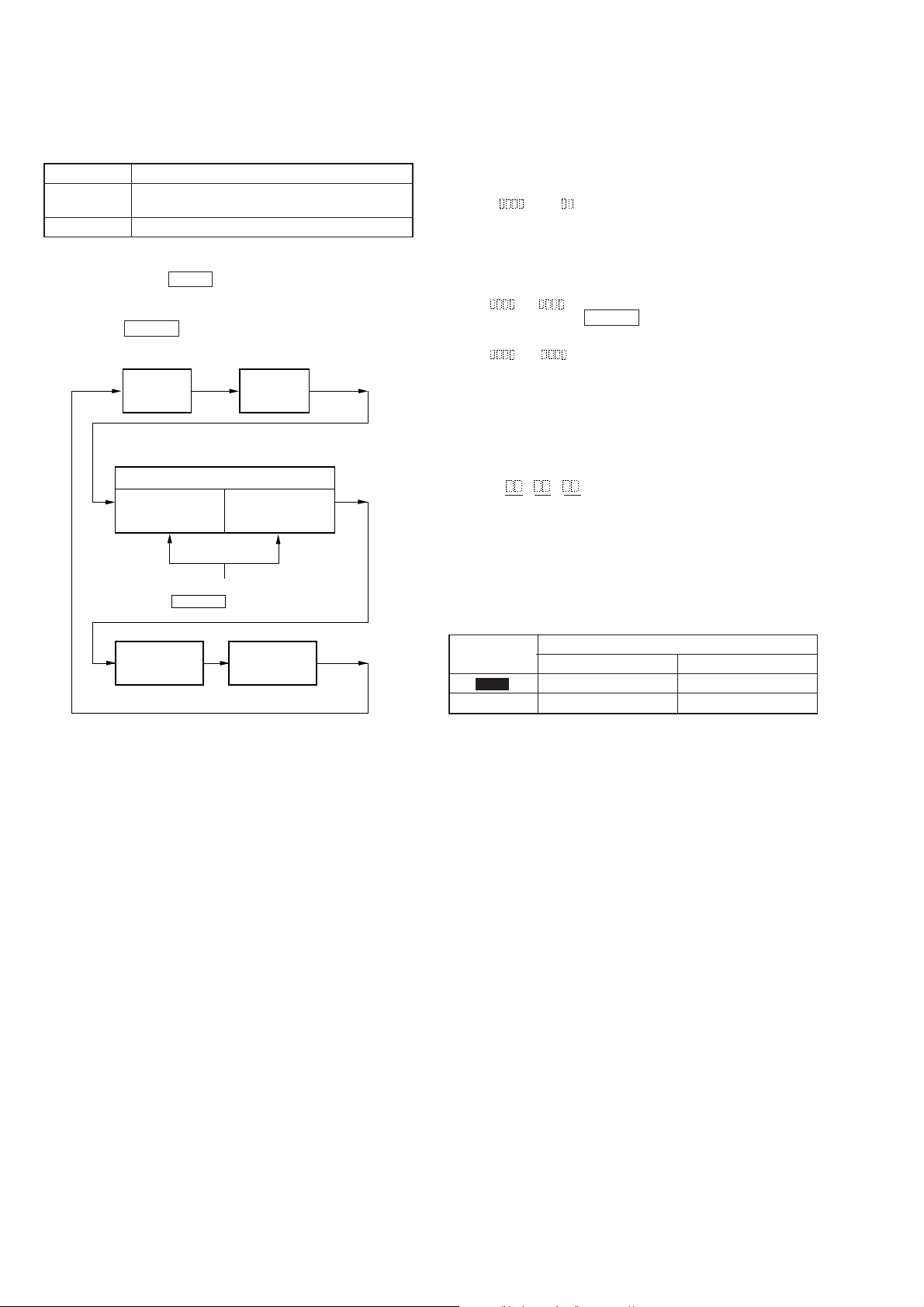
4-11. TEST MODE DISPLAYS
Each time the POWER button pressed, the display changes in the
following order.
Mode
display
Address display
ADIP address
display
Error rate
display
SUB Q address
display
1. MODE display
Displays “TEMP ADJUST”, “CPLAY MODE”, etc..
2. Error rate display
Error rates are displayed as follows.
C1= AD=
C1= : Indicates C1 error
AD= : Indicates ADER
3. Address display
Address are displayed as follows.
h= a= (MO groove)
With this display, if POWER button is pressed, the following
will be displayed.
h= s= (MO pit and CD)
h=: Header address
s=: SUB Q address
a=: ADIP address
Note: “—” is displayed when the address cannot be read.
4. Auto gain display
Auto gain are displayed as follows.
AG = / [ ]
A B C
A= Focus servo gain coefficient
B= Tracking servo gain coefficient
C= [OK] or [NG] or [ - -] (not converged)
Change over the display with the
POWER button.
Auto gain
display
Note: Auto gain display and IVR display are not used in servicing.
IVR
display
4-12. MEANINGS OF OTHER DISPLAYS
Table 4-4.
Display
REC Recording mode on Recording mode off
DISC High reflection rate disc Low reflection rate disc
Light Off
Contents
– 18 –
SECTION 5
d
ELECTRICAL ADJUSTMENT
MD SECTION
5-1. PRECAUTIONS FOR CHECKING LASER DI-
ODE EMISSION
T o check the emission of the laser diode during adjustments, nev er
view directly from the top as this may lose your eyesight.
5-2. PRECAUTIONS FOR USE OF OPTICAL
PICK-UP (KMS-260A)
As the laser diode in the optical pick-up is easily damaged by static
electricity, solder the laser tap of the flexib le board when using it.
Before disconnecting the connector, desolder first. Before connecting the connector, be careful not to remove the solder. Also
tale adequate measures to prevent damage by static electricity.
Handle the flexible board with care as it breaks easily.
Pick-up
Flexible boar
Laser tap
Optical pick-up flexible board
5-3. PRECAUTIONS FOR ADJUSTMENTS
1) When replacing the following parts, perform the adjustments
and checks with ® in the order shown in the following table.
Table 5-1.
Optical
Pick-up
1.Temperature
compensation × ®® ®
offset adjustment
2.Laser power ®® × ®
adjustment
3.Traverse
adjustment
4.Focus bias
adjustment
5.Error rate check ®® × ®
IC171 D101
®® × ®
®® × ®
2) Set the test mode when performing adjustments.
After completing the adjustments, exit the test mode.
3) Perform the adjustments in the order shown.
4) Use the following tools and measuring devices.
• Check Disc (MD) TDYS-1
(Parts No. 4-963-646-01)
• Laser power meter LPM-8001
(Parts No. J-2501-046-A)
• Oscilloscope (Measure after preforming CAL of prove.)
• Digital voltmeter
• Thermometer
5) When observing several signals on the oscilloscope, etc., make
sure that VC and ground do not connect inside the oscilloscope.
(VC and ground will become short-circuited)
BD board
IC101, IC121, IC192
5-4. CREATING MO CONTINUOUSLY
RECORDED DISC
* This disc is used in focus bias adjustment and error rate check.
The following describes how to create a MO continuous recording disc.
1. Set the test mode.
2. Insert a MO disc (blank disc) commercially available.
3. Turn the VOLUME knob display “CREC MODE”.
4. Press the p (CD) button and display “CREC MID”.
“CREC (0300)” is displayed for a moment and recording starts.
5. Complete recording within 5 minutes.
6. Press the ^ (CD) button and stop recording.
7. Press the § (MD) button and remove the MO disc.
The above has been how to create a continuous recording data for
the focus bias adjustment and error rate check.
Note: Be careful not to apply vibration during continuous recording.
– 19 –

5-5. TEMPERATURE COMPENSATION OFFSET
r
r
ADJUSTMENT
Save the temperature data at that time in the non-volatile memory
as 25 °C reference data.
Notes:
1. Usually, do not perform this adjustment.
2. Perform this adjustment in an ambient temperature of 22 °C to
28 °C. Perform it immediately after the power is turned on
when the internal temperature of the unit is the same as the
ambient temperature of 22 °C to 28 °C.
3. When D101 has been replaced, perform this adjustment after
the temperature of this part has become the ambient temperature.
5-6. LASER POWER ADJUSTMENT
Connection:
Optical pick-up
objective lens
BD (MD) board
TP1004 (I+3 V)
TP1005 (IOP)
laser
power mete
digital voltmete
+
–
Adjusting Method:
1. Turn the VOLUME knob and display “TEMP ADJUST”.
2. Press the p (CD) button to change the display to “TEMP =
” (The numbers “
” displayed shows you the current tem-
perature.)
3. To save the data, press the p (CD) button.
When not saving the data, press the ^ (CD) button.
4. When the p (CD) button is pressed, “TEMP= SAVE” will
be displayed for some time, followed by “TEMP ADJUST”.
When the ^ (CD) button is pressed, “TEMP ADJUST” will
be displayed immediately.
Specifications:
The temperature should be within “E0-EF”, “F0-FF”, “00-0F”,
“10-1F” and “20-2F”.
Adjusting Method:
1. Set the laser power meter on the objective lens of the optical
pick-up. (When it cannot be set properly, press the
= 0 button or ) + button and move the optical
pick-up.)
Connect the digital voltmeter to TP1004 (I+3 V) and TP1005
(IOP) of the BD (MD) board.
2. Turn the VOLUME knob and display “LDPWR ADJUST”.
(Laser power: for adjustment)
3. Press the p (CD) button and display “LD 0.9 mW $ ”.
4. Turn the VOLUME knob so that the reading of the laser power
meter becomes 0.82 to 0.91 mW.
Set the range control on the laser power meter to 10 mW, then
press the p (CD) button to save the adjustment result in the
non- volatile memory.
(“LD SAVE $
5. Then “LD 7.0 mW $
” will be displayed for a moment.)
”will be displayed.
6. Turn the VOLUME knob so that the reading of the laser power
meter becomes 6.9 to 7.1 mW, press the p (CD) button and
save the adjustment result in the nonvolatile memory.
(“LD SAVE $
Note: Do not perform the emission with 7.0 mW more than 15 seconds
continuously.
” will be displayed for a moment.)
7. Turn the VOLUME knob and display “LDPWR CHECK”.
8. Press the p (CD) button and display “LD 0.9 mW $ ”.
Check that the reading of the laser power meter becomes 0.80
to 0.96 mW.
9. Press the p (CD) button and display “LD 7.0 mW $ ”.
Check that the reading of the laser power meter and digital voltmeter satisfy the specified value.
Specification:
Laser power meter reading:7.0 ± 0.2 mW
Digital voltmeter reading : Optical pick-up displayed value ±10%
(Optical pick-up label)
KMS260A
27X40
B0567
lOP=56.7 mA in this case
lOP (mA) = Digital voltmeter reading (mV)/1 (
Ω
)
10. Press the ^ (CD) button and display “LDPWR CHECK”,
and stop the laser emission.
(The ^ (CD) button is effective a t all times to stop the laser
emission.)
– 20 –
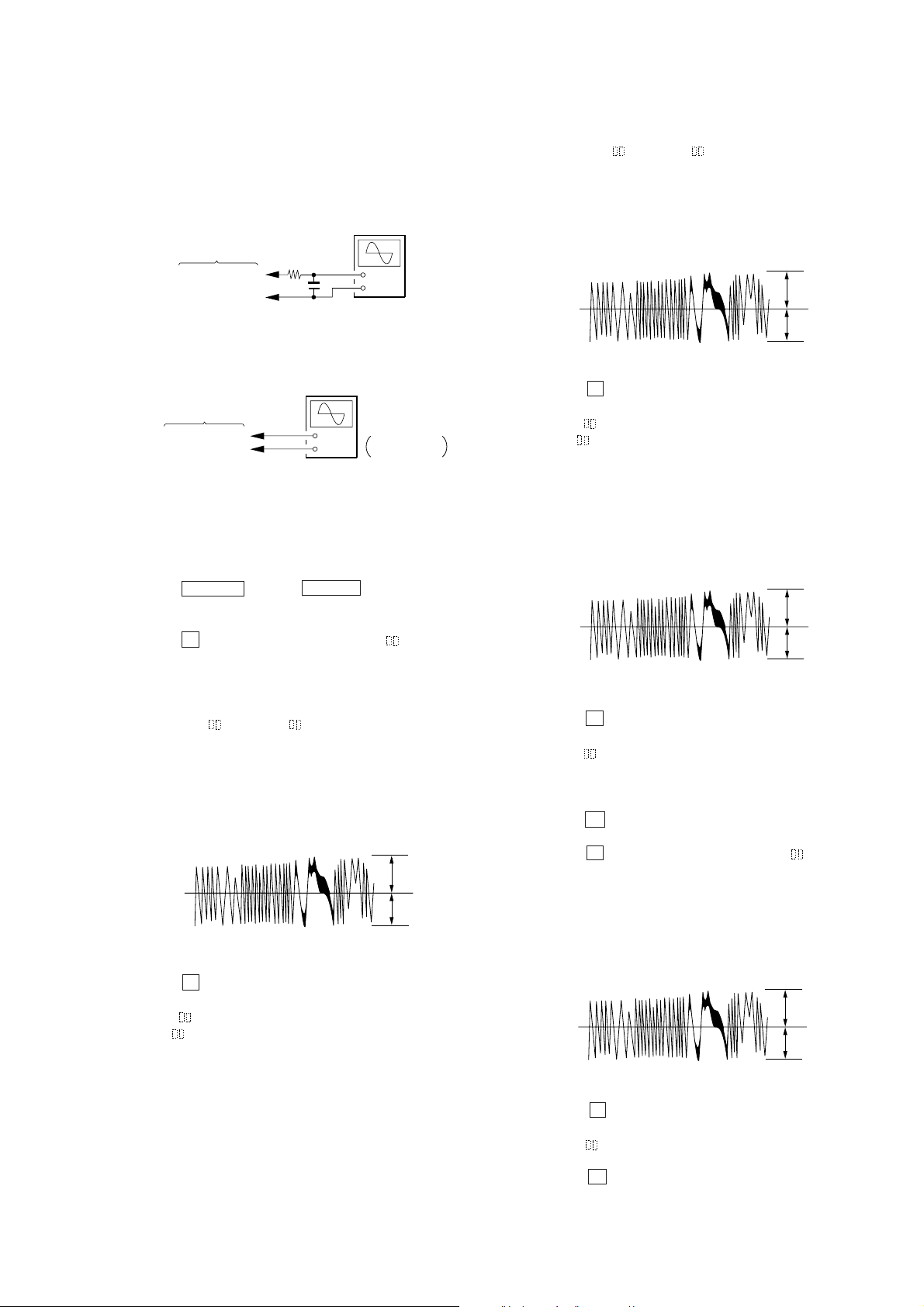
5-7. TRAVERSE (E-F BALANCE) ADJUSTMENT
Note 1: Data will be erased during MO reading if a recorded disc is used
in this adjustment.
Note 2: If the tra ver se wa v eform is not clear, connect the oscilloscope as
shown in the following f igure so that it can be seen more clearly.
oscilloscope
(DC range)
BD (MD) board
TP1002 (TEO)
TP1003 (VC)
Connection:
BD (MD) board
TP1002 (TEO)
TP1003 (VC)
Adjusting Method:
1. Connect an oscilloscope to TP1002 (TEO) and TP1003 (VC)
of the BD (MD) board.
2. Load a MO disc (any available on the market). (Refer to note
1.)
3. Press the = 0 button or ) + button and move the
optical pick-up outside the pit.
4. Turn the VOLUME knob and display “EF MO ADJUST”.
5. Press the p (CD) button and display “EFB=
(Laser power READ power/focus serv o ON/tracking servo OFF/
spindle (S) servo ON)
6. Turn the VOLUME knob so that the waveforms of the oscilloscope becomes the specified value. (When the VOLUME knob
is turned, the “ ” of “EFB=
form changes.)
In this adjustment, waveform varies at interv als of approx. 2%.
Adjust the waveform so that the specified value is satisfied as
much as possible.
(MO read power traverse adjustment)
VC
specification: A=B
7. Press the p (CD) button, and save the result of adjustment to
the non-volatile memory.
(“EFB= SAVE” will be displayed for a moment. Then
“EFB=
MO-W” will be displayed.)
330 k
Ω
10 pF
oscilloscope
(DC range)
+
–
+
–
V: 0.1 V/div
H: 10 ms/div
MO-R” changes and the wave-
A
B
MO-R”.
8. Turn the V OLUME knob so that the wa veforms of the oscilloscope becomes the specified value. (When the VOLUME knob
is turned, the “ ” of “EFB= MO-W” changes and the w aveform changes.)
In this adjustment, waveform varies at interv als of approx. 2%.
Adjust the waveform so that the specified value is satisfied as
much as possible.
(MO write power traverse adjustment)
(Traverse Wav eform)
A
VC
B
specification: A=B
9. Press the p (CD) button, and save the result of adjustment to
the non-volatile memory.
(“EFB=
“EFB=
SAVE” will be displayed for a moment. Then
MO-P” will be displayed.)
10. The optical pick-up moves to the pit area automatically and
servo is imposed.
11. Turn the VOLUME knob until the waveforms of the oscilloscope moves closer to the specified value.
In this adjustment, waveform varies at interv als of approx. 2%.
Adjust the waveform so that the specified value is satisfied as
much as possible.
(Traverse Wav eform)
A
VC
B
specification: A=B
12. Press the p (CD) button, and save the result of adjustment to
the non-volatile memory.
(“EFB= SAVE” will be displayed for a moment. Then
“EFBAL ADJUST” will be displayed.)
The disc stops rotating automatically.
13. Turn the VOLUME knob and display “EF CD ADJUST”
14. Press the § (MD) button and remove the MO disc.
15. Load the test disc TDYS-1.
16. Press the p (CD) button and display “EFB= CD”.
Servo is imposed automatically.
17. Turn the VOLUME knob until the waveforms of the oscilloscope moves closer to the specified value.
In this adjustment, waveform varies at interv als of approx. 2%.
Adjust the waveform so that the specified value is satisfied as
much as possible.
(Traverse Wav eform)
A
VC
B
specification: A=B
18. Press the p (CD) button, and save the result of adjustment to
the non-volatile memory.
(“EFB= SAVE” will be displayed for a moment. Then
“EFBAL CD” will be displayed.)
19. Press the § (MD) button and remove the test disc TDYS-1.
– 21 –
5-8. FOCUS BIAS ADJUSTMENT
Adjusting Method:
1. Load a continuously recorded disc (Refer to “5-4. Creating MO
Continuously Recorded Disc”.).
2. Turn the VOLUME knob and display “CPLAY MODE”.
3. Press the p (CD) button and display “CPLAY MID”.
4. Press the POWER button when “C1=
played.
5. Turn the VOLUME knob and display “FBIAS ADJUST”.
6. Press the p (CD) button and display “ / a= ”.
The first four digits indicate the C1 error rate, the two digits
after [/] indicate ADER, and the 2 digits after [a=] indicate the
focus bias value.
7. Turn the VOLUME knob in the clockwise direction and find
the focus bias value at which the C1 error rate becomes 220.
(Refer to note 2.)
8. Press the p (CD) button and display “ / b= ”.
9. Turn the VOLUME knob in the counterclockwise derection and
find the focus bias value at which the C1 error rate becomes
220. (Refer to note 2.)
10. Press the p (CD) button and display “ / c= ”.
11. Check that the C1 error rate is below 50 and ADER is 00.
Then press the p (CD) button.
12. If the “( )” in “ - - ( )” is above 20, press the
p (CD)button.
If below 20, press the ^ (CD) button and repeat the adjustment from step 2 again.
13. Press the ^ (CD) button and press the § (MD) button to
remove the continuously recorded disc.
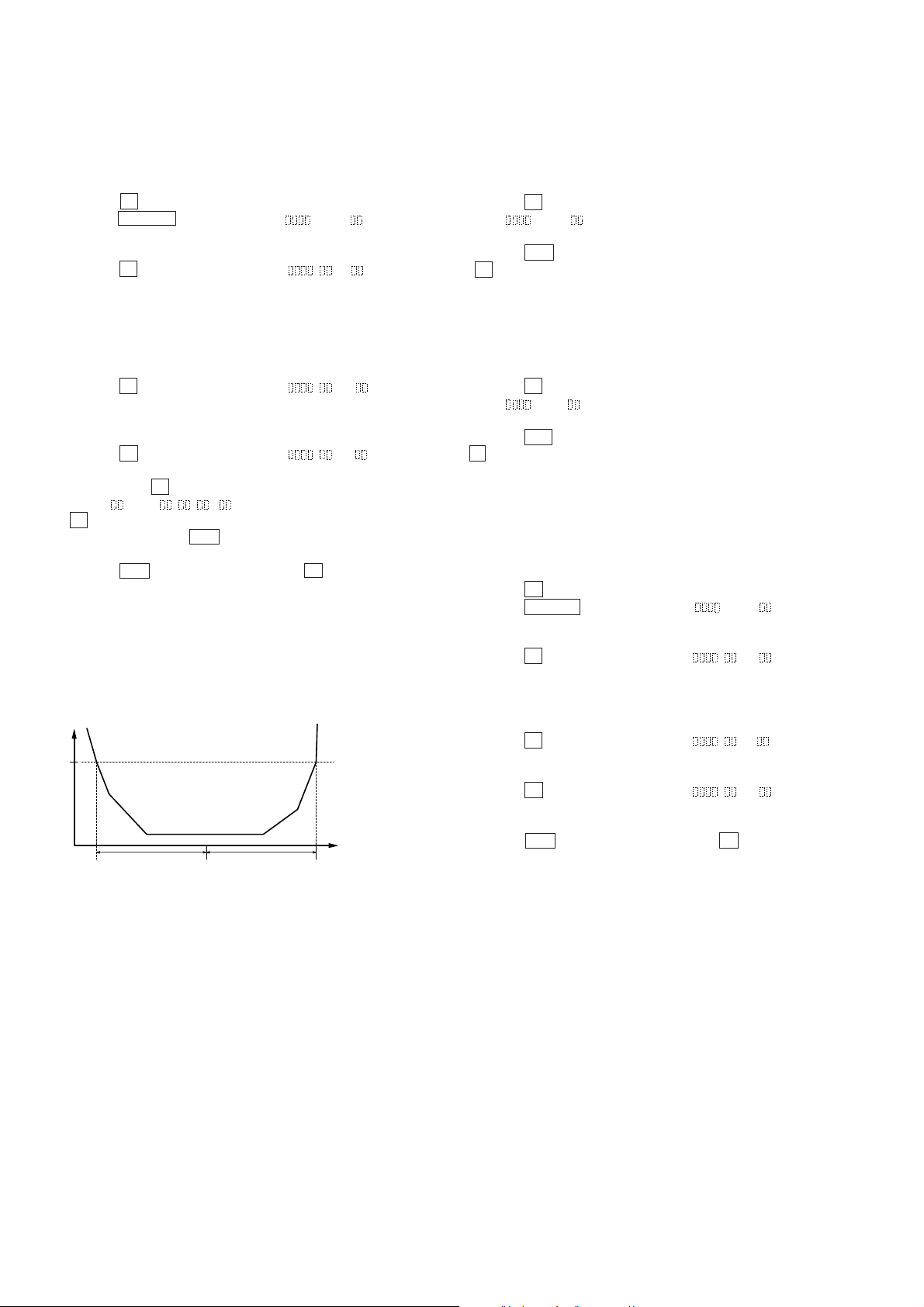
Note 1: The relation between the C1 error and focus bias is as shown in the
following figure. Find points a and b in the following f igure using
the above adjustment. The focal point position c is automatically
calculated from points a and b.
Note 2: As the C1 error rate changes, perform the adjustment using the av-
erage vale.
C1 error
220
bca
AD= ” is dis-
Focus bias value
(F. BIAS)
5-9. ERROR RATE CHECK
5-9-1. CD Error Rate Check
Checking Method:
1. Load a test disc TDYS-1.
2. Turn the VOLUME knob and display “CPLAY MODE”.
3. Press the p (CD) button and display “CPLAY MID”.
4. “C1= AD= ” is displayed.
5. Check that the C1 error is below 20.
6. Press the ^ (CD) button, stop playback, press the
§ (MD) EJECT button, and remove the test disc.
5-9-2. MO Error Rate Check
Checking Method:
1. Load a continuously recorded disc (Refer to “5-4. Creating MO
Continuously Recorded Disc”.).
2. Turn the VOLUME knob and display “CPLAY MODE”.
3. Press the p (CD) button and display “CPLAY MID”.
4. “C1= AD= ” is displayed.
5. If the C1 error is below 50, check that ADER is 00.
6. Press the ^ (CD) button, stop playback, press the
§ (MD) button, and remove the continuously recorded disc.
5-10. FOCUS BIAS CHECK
Change the focus bias and check the focus tolerance amount.
Checking Method:
1. Load a continuously recorded disc (Refer to “5-4. Creating MO
Continuously Recorded Disc”.).
2. Turn the VOLUME knob and display “CPLAY MODE”.
3. Press the p (CD) button and display “CPLAY MID”.
4. Press the POWER button when “C1= AD= ” is displayed.
5. Turn the VOLUME knob and display “FBIAS CHECK”.
6. Press the p (CD) button and display “
The first four digits indicate the C1 error rate, the two digits
after [/] indicate ADER, and the 2 digits after [c=] indicate the
focus bias value.
Check that the C1 error is below 50 and ADER is 00.
7. Press the p (CD) button and display “ / b= ”.
Check that the C1 error is not below 220 and ADER is not above
00 every time.
8. Press the p (CD) button and display “ / a= ”.
Check that the C1 error is not below 220 and ADER is not above
00 every time.
9. Press the ^ (CD) button, next press the § (MD) button,
and remove the continuously recorded disc.
Note 1: If the C1 error and ADER are above 00 at points a or b, the focus
bias adjustment may not have been carried out properly. Adjust
perform the beginning again.
/ c= ”.
– 22 –
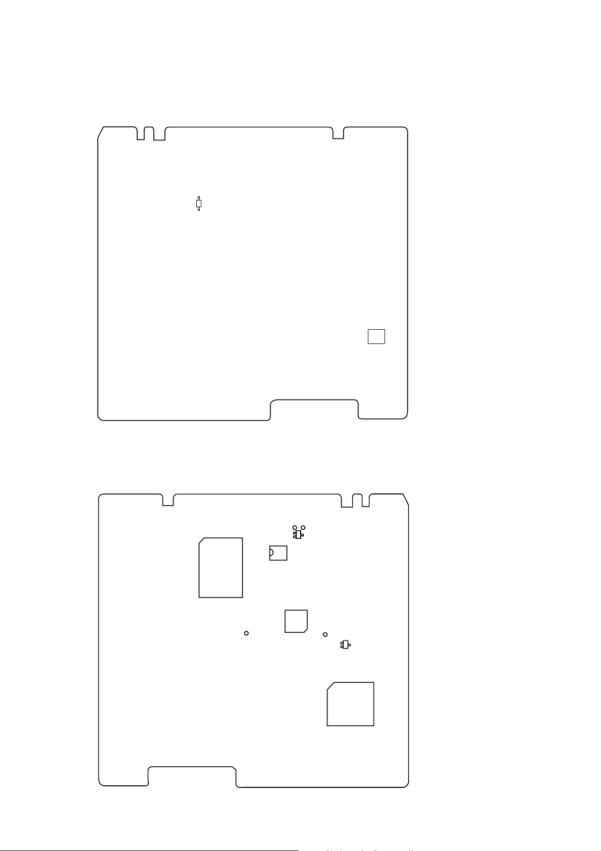
5-11. ADJUSTING POINTS AND CONNECTING POINTS
[BD (MD) BOARD] (SIDE A)
D101
IC192
[BD (MD) BOARD] (SIDE B)
IC316
TP
(TEO)
TP (IOP)
IC171
TP (I + 3V)
Q163
TP
(VC)
IC101
Q102
IC121
– 23 –
 Loading...