

Sony HCD-EC68,HCD-EC78 Service Manual
HCD-EC68/EC78
Q
Q
3
7
6
3
1
5
1
5
0
SERVICE MANUAL
Ver. 1.0 2008.02
TEL 13942296513 QQ 376315150 892498299
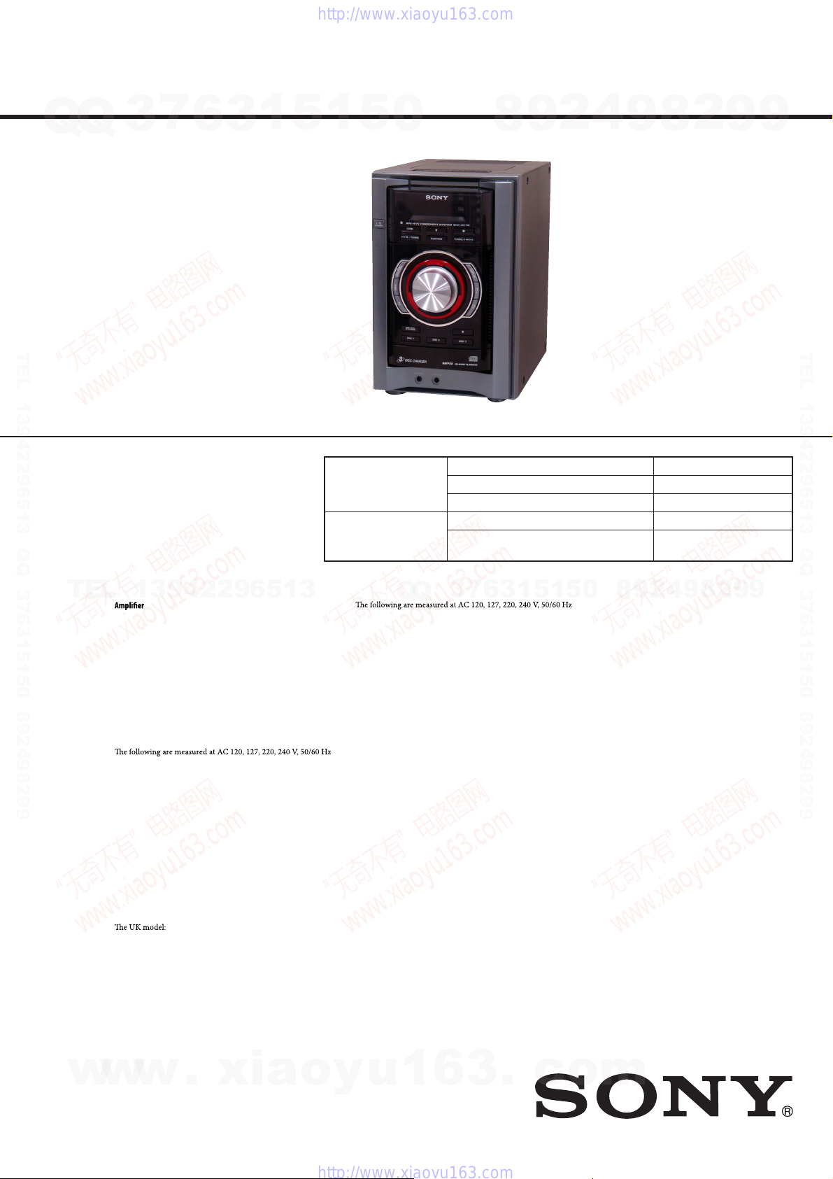
• HCD-EC68 is the amplifi er, CD player, tape
deck (except UK model) and tuner section in
MHC-EC68.
• HCD-EC78 is the amplifi er, CD player, tape
deck and tuner section in MHC-EC78.
Photo : HCD-EC78
CD
Section
Tape deck
Section
(EXCEPT EC68: UK)
Model Name Using Similar Mechanism
Mechanism Type
Optical Pick-up Block Name
Model Name Using Similar Mechanism
Tape Transport Mechanism Type
8
9
2
4
9
8
2
9
AEP Model
E Model
HCD-EC68/EC78
UK Model
Australian Model
HCD-EC68
NEW
CDM88A-K6BD90-WOD
KSM-213DCP
HCD-EC77
TCM-J1 or
CS-21SC-900TP
9
TEL 13942296513 QQ 376315150 892498299
TEL
13942296513
section
HCD-EC78
European and Russian models:
Power output (rated):
Low channel
55 W + 55 W (at 8 Ω, 1 kHz, 1% THD)
High chann el
55 W + 55 W (at 8 Ω, 8 kHz, 1% THD)
RMS output power (reference):
Low channel
75 W + 75 W (per channel at 8 Ω, 1 kHz, 10% THD)
High chann el
75 W + 75 W (per channel at 8 Ω, 8 kHz, 10% THD)
Other models:
Power output (rated):
Low channel
50 W + 50 W (at 8 Ω, 1 kHz, 1% THD)
High chann el
50 W + 50 W (at 8 Ω, 8 kHz, 1% THD)
RMS output power (reference):
Low channel
70 W + 70 W (per channel at 8 Ω, 1 kHz, 10% THD)
High chann el
70 W + 70 W (per channel at 8 Ω, 8 kHz, 10% THD)
HCD-EC68
European and Russian models (except for the UK model):
Power output (rated):
50 W + 50 W (at 6 Ω, 1 kHz, 1% THD)
RMS output power (reference):
70 W + 70 W (per channel at 6 Ω, 1 kHz, 10% THD)
Power output (rated):
55 W + 55 W (at 6 Ω, 1 kHz, 1% THD)
RMS output power (reference):
75 W + 75 W (per channel at 6 Ω, 1 kHz, 10% THD)
Other models:
SPECIFICATIONS
Q
Q
Power output (rated):
50 W + 50 W (at 6 Ω, 1 kHz, 1% THD)
RMS output power (reference):
70 W + 70 W (per channel at 6 Ω, 1 kHz, 10% THD)
Inputs
AUDIO IN (stereo mini jack): Sensitivity 800 mV, impedance
22 kilohms
Outputs
PHONES (stereo mini jack): Accepts headphones with an
impedance of 8 Ω or more
SPEAKER: impedance
HCD-EC78: 8 Ω
HCD-EC68: 6 Ω
CD player section
System: Compact disc and digital audio system
Laser: Semiconductor laser (λ=770 – 810 nm)
Emission duration: continuous
Frequency response: 20 Hz – 20 kHz
Signal-to-noise ratio: More than 90 dB
Dynamic range: More than 88 dB
Tape deck section (except fortheUKmodel)
Recording system: 4-track 2-channel, stereo
3
7
6
3
1
5
COMPACT DISC DECK RECEIVER
1
9
9
2
8
9
4
2
9
8
0
5
Tuner section
FM stereo, FM/AM superheterodyne tuner
Antenna:
FM lead antenna
AM loop antenna
FM tuner section:
Tuning range:
87.5 – 108.0 MHz (50 kHz step)
Intermediate frequency: 10.7 MHz
AM tuner section:
Tuning range
Australian, Pan-American models:
530 – 1,710 kHz (with 10 kHz tuning interval)
531 – 1,710 kHz (with 9 kHz tuning interval)
European and Russian models:
531 – 1,602 kHz (with 9 kHz tuning interval)
Other models:
530 – 1,610 kHz (with 10 kHz tuning interval)
531 – 1,602 kHz (with 9 kHz tuning interval)
Intermediate frequency: 450 kHz
– Continued on next page –
EXCEPT HCD-EC68: UK MODEL
HCD-EC68: UK MODEL
w
w
9-889-007-01
2008B05-1
©
w
2008.02
.
xia
Sony Corporation
Audio Business Group
Published by Sony Techno Create Corporation
o
y
u
1
6
3
COMPACT DISC RECEIVER
.
c
o
m
HCD-EC68/EC78
General
Power requirements:
Q
Q
European and Russian models: AC 230 V, 50/60 Hz
Mexican model: AC 127 V, 60 Hz
Argentine model: AC 220 V, 50/60 Hz
Australian model: AC 230 – 240 V, 50/60 Hz
Other models: AC 120, 220 or 230 – 240 V, 50/60 Hz,
adjustable with voltage selector
Power consumption:
HCD-EC78
European and Russian models: 160 W
Mexican model: 160 W
Other models: 150 W
HCD-EC68
European and Russian models (except for the UK model): 100 W
Other models: 100 W
Dimensions (w/h/d) (excl. speakers):
Approx. 200 × 306 × 415 mm
Mass (excl. speakers):
TEL 13942296513 QQ 376315150 892498299
HCD-EC78
European and Russian models: Approx. 6.0 kg
Other models: Approx. 6.3 kg
HCD-EC68
European and Russian models (except for the UK model):
Other models: Approx. 5.3 kg
0.5 W (in Power Saving Mode)
TEL
Notes on chip component replacement
• Never reuse a disconnected chip component.
• Notice that the minus side of a tantalum capacitor may be damaged by heat.
Flexible Circuit Board Repairing
• Keep the temperature of soldering iron around 270 °C during
repairing.
• Do not touch the soldering iron on the same conductor of the
circuit board (within 3 times).
• Be careful not to apply force on the conductor when soldering
or unsoldering.
CAUTION
Use of controls or adjustments or performance of procedures other than
those specifi ed herein may result in hazardous radiation exposure.
7
3
0.5 W (in Power Saving Mode)
Approx. 5.3 kg
6
3
1
13942296513
This appliance is
classified as a CLASS 1
LASER product. This
marking is located on the
rear exterior.
5
1
5
0
1. SERVICING NOTES ............................................. 3
2. GENERAL .................................................................. 6
3. DISASSEMBLY
3-1. Disassembly Flow ........................................................... 8
3-2. Side Panel (L)/(R) ........................................................... 9
3-3. Top Panel (EC68: UK model)/Top Panel Block
(Except EC68: UK model) .............................................. 9
3-4. Tape Mechanism Deck (Except EC68: UK model) ........ 10
3-5. MAIN Board ................................................................... 10
3-6. Front Panel Section ......................................................... 11
3-7. Back Panel Block ............................................................ 11
3-8. CD Mechanism Block ..................................................... 12
3-9. BU Block ........................................................................ 12
3-10. OP Base Assy (KSM-213D) ........................................... 13
4. TEST MODE ............................................................ 14
5. MECHANICAL ADJUSTMENTS ...................... 18
6. ELECTRICAL ADJUSTMENTS ........................ 18
7. DIAGRAMS
7-1. Printed Wiring Board - CD Board - ................................ 24
7-2. Schematic Diagram - CD Board - ................................... 25
7-3. Printed Wiring Board
- DECK Board (Except EC68: UK model) - .................. 26
7-4. Schematic Diagram
- DECK Board (Except EC68: UK model) - .................. 26
Q
Q
7-5. Printed Wiring Board - MAIN Board - ........................... 27
7-6. Schematic Diagram - MAIN Board (1/2) - ..................... 28
7-7. Schematic Diagram - MAIN Board (2/2) - ..................... 29
7-8. Printed Wiring Board - HI AMP Board (EC78) - ........... 30
7-9. Schematic Diagram - HI AMP Board (EC78) - .............. 30
7-10. Printed Wiring Board - LOW AMP Board - ................... 31
7-11. Schematic Diagram - LOW AMP Board - ...................... 31
7-12. Printed Wiring Board - PANEL Board (Suffi x-12) - ...... 32
7-13. Printed Wiring Board - PANEL Board (Suffi x-13) - ...... 32
7-14. Schematic Diagram - PANEL Board - ............................ 33
7-15. Printed Wiring Boards - KEY Section - .......................... 34
7-16. Schematic Diagram - KEY Section - .............................. 34
7-17. Printed Wiring Board - PT Board - ................................. 35
7-18. Schematic Diagram - PT Board - .................................... 36
8. EXPLODED VIEWS
8-1. Panel Section ................................................................... 44
8-2. Tape Deck Section (Except EC68: UK).......................... 45
8-3. Front Panel Section ......................................................... 46
8-4. Chassis Section ............................................................... 47
8-5. Main Section ................................................................... 48
8-6. CD Mechanism Section (CDM88A-K6BD90-WOD) .... 49
9. ELECTRICAL PARTS LIST .............................. 50
3
7
TABLE OF CONTENTS
4
2
9
8
0
5
1
5
1
3
6
9
8
9
8
2
4
2
9
8
9
2
9
9
TEL 13942296513 QQ 376315150 892498299
9
SAFETY-RELATED COMPONET WARNING!
COMPONENTS IDENTIFIED BY MARK 0 OR DOTTED LINE
WITH MARK 0 ON THE SCHEMATIC DIAGRAMS AND IN
THE PARTS LIST ARE CRITICAL TO SAFE OPERATION.
w
w
REPLACE THESE COMPONENTS WITH SONY PARTS
WHOSE PART NUMBERS APPEAR AS SHOWN IN THIS
MANUAL OR IN SUPPLEMENTS PUBLISHED BY SONY.
2
w
.
xia
o
y
u
1
6
3
.
c
o
m
SECTION 1
SERVICING NOTES
HCD-EC68/EC78
NOTES ON HANDLING THE OPTICAL PICK-UP
Q
TEL 13942296513 QQ 376315150 892498299
BLOCK OR BASE UNIT
Q
The laser diode in the optical pick-up block may suffer electrostatic break-down because of the potential difference generated by the
charged electrostatic load, etc. on clothing and the human body.
During repair, pay attention to electrostatic break-down and also
use the procedure in the printed matter which is included in the
repair parts.
The fl exible board is easily damaged and should be handled with
care.
NOTES ON LASER DIODE EMISSION CHECK
The laser beam on this model is concentrated so as to be focused
on the disc refl ective surface by the objective lens in the optical
pickup block. Therefore, when checking the laser diode emission,
observe from more than 30 cm away from the objective lens.
UNLEADED SOLDER
Boards requiring use of unleaded solder are printed with the leadfree mark (LF) indicating the solder contains no lead.
(Caution: Some printed circuit boards may not come printed with
Unleaded solder has the following characteristics.
• Unleaded solder melts at a temperature about 40 °C higher
than ordinary solder.
Ordinary soldering irons can be used but the iron tip has to be
applied to the solder joint for a slightly longer time.
Soldering irons using a temperature regulator should be set to
about 350 °C.
TEL
Caution: The printed pattern (copper foil) may peel away if the
• Strong viscosity
Unleaded solder is more viscou-s (sticky, less prone to fl ow)
than ordinary solder so use caution not to let solder bridges
occur such as on IC pins, etc.
• Usable with ordinary solder
It is best to use only unleaded solder but unleaded solder may
also be added to ordinary solder.
7
3
the lead free mark due to their particular size)
: LEAD FREE MARK
6
3
1
5
13942296513
heated tip is applied for too long, so be careful!
1
5
0
Q
Q
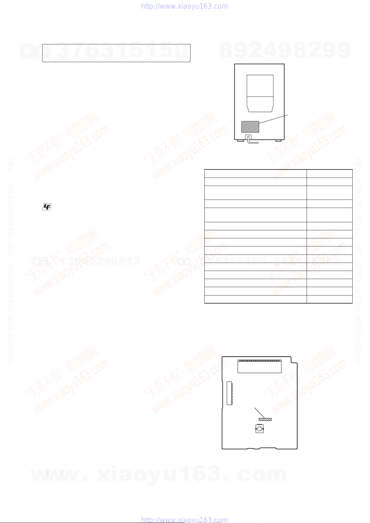
MODEL IDENTIFICATION
– Back Panel –
EC68: AEP model
EC68: 120V AC area in E, Chilean and
Peruvian models
EC78: AEP model
EC78: 120V AC area in E, Chilean and
Peruvian models
EC68: Russian model
EC68: UK model
EC68: 240V AC area in E model
EC68: Australian model
EC68: Mexican model
7
3
EC68: Argentina model
EC78: Russian model
EC78: 240V AC area in E model
EC78: Mexican model
EC78: Argentina model
8
6
3
9
1
4
2
Model Part No.
0
5
1
5
9
8
9
2
8
MODEL
NUMBER
LABEL
9
4
2
8
9
9
3-296-777-0[]
3-296-779-0[]
3-296-780-0[]
3-296-782-0[]
3-398-081-0[]
3-398-082-0[]
3-398-083-0[]
3-398-084-0[]
3-398-085-0[]
9
9
2
3-398-086-0[]
3-398-088-0[]
3-398-090-0[]
3-398-091-0[]
3-398-092-0[]
TEL 13942296513 QQ 376315150 892498299
RELEASING THE DISC TRAY LOCK
The disc tray lock function for the antitheft of an demonstration
disc in the store is equipped.
Releasing Procedure:
1. Press [I/
2. Press the [FUNCTION] button to select CD function.
3. While pressing the [
seconds).
4. The message “UNLOCKED” is displayed and the disc tray is
unlocked.
Note: When “LOCKED” is displayed, the slot lock is not released by
w
w
] button to turn the power on.
1
] button, press the [Z] button for more 5
x
turning power on/off with the [I/1] button.
w
.
xia
o
y
u
1
SUFFIX-12/SUFFIX-13 DISCRIMINATION OF PANEL
BOARD
– PANEL Board (Component Side) –
LCD301
CN304
Suffix-12 : 1-875-490-12
Suffix-13 : 1-875-490-13
S301
S301
6
3
.
c
o
m
3
HCD-EC68/EC78
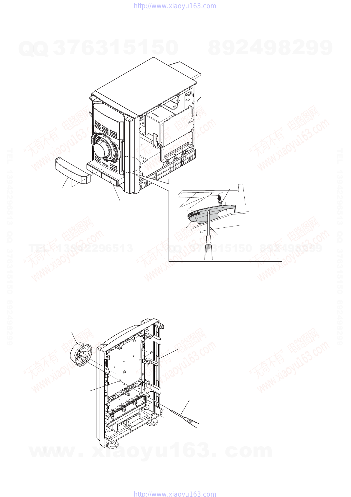
HOW TO OPEN THE TRAY WHEN POWER SWITCH TURN OFF
Q
Q
3
7
6
3
1
5
1
5
0
8
9
2
4
9
8
2
9
9
TEL 13942296513 QQ 376315150 892498299
door (CD)
pull the tray by the hand.
gear
TEL
HOW TO REMOVE THE KNOB (VOL)
13942296513
Q
Q
3
7
lever
Turn a gear by a driver
till a lever falls down
to the position of the figure.
5
1
3
6
1
5
0
8
9
2
4
9
8
2
9
TEL 13942296513 QQ 376315150 892498299
9
4
w
w
knob (VOL)
w
hole
.
xia
front panel block
(back view)
Push the knob (VOL) by the flat head driver.
o
y
u
1
6
3
.
c
o
m
Q
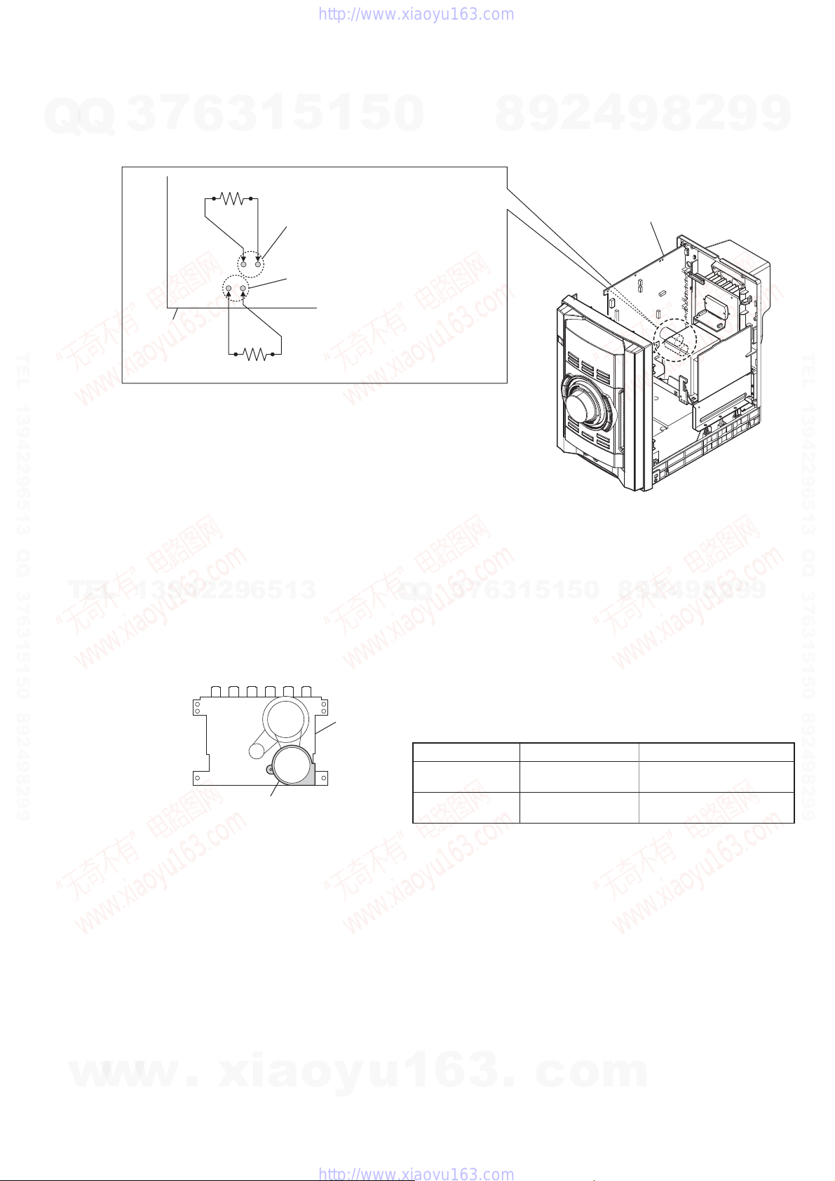
CAPACITOR DISCHARGE FOR ELECTRIC SHOCK PREVENTION
Q
7
3
In checking the MAIN board, make a capacitor discharge
of C622, C676, C677 and C678 for electric shock prevention.
6
800 Ω/2W
3
1
5
1
5
0
8
9
2
4
HCD-EC68/EC78
2
9
8
9
9
C626 (EC68/EC78: E2, E3, E51, MX, AR),
C678 (EC78: AEP, RU)
C622 (EC68/EC78: E2, E3, E51, MX, AR),
C677 (EC78: AEP, RU)
MAIN board
TEL 13942296513 QQ 376315150 892498299
800 Ω/2W
• Abbreviation
AR : Argentina model
E2 : 120V AC area in E model
E3 : 240V AC area in E model
E51 : Chilean and Peruvian models
MX : Mexican model
RU : Russian model
TEL
13942296513
HOW TO DISTINGUISH TAPE MECHANISM DECK (EXCEPT EC68: UK MODEL)
Two kinds of tape mechanism decks installed by this set exist.
Q
Q
3
7
6
3
1
5
1
5
0
MAIN board
2
9
8
4
9
8
2
9
TEL 13942296513 QQ 376315150 892498299
9
Please do the repair exchange after confi rming which tape mechanism deck set of the repair according to how to distinguish the fi gure
below.
tape deck
motor
Metal part: TCM-J1
Mold part: CS-21SC-900TP
Tape Deck Name Tape Deck Part No. Belt Part No.
TCM-J1
CS-21SC-900TP
A-1527-851-A
1-797-575-11
2-670-389-01 BELT (1)
3-214-817-01 BELT (FR)
2-688-621-01 BELT (R/F)
2-688-622-01 BELT (MAIN)
w
w
w
.
xia
o
y
u
1
6
3
.
c
o
m
5
HCD-EC68/EC78
SECTION 2
GENERAL
Compatibility with all MP3 encoding/writing soware, recording
Basic Operations
Q
Q
3
*
7
Selecting a music source
Press the following buttons (or press FUNCTION
1
2)
(connected
5
6
3
repeatedly).
To select Press
CD
Tun e r
1)
Tap e
Component
using an audio cord)
1)
Except for the UK model.
2)
If the component has the AVLS (Automatic Volume Limiter System)
or BASS BOOST function, turn o the function to avoid distorted
sound from the speakers.
1
5
CD
.
TUNER/BAND
TAP E .
FUNCTION
repeatedly until “AUDIO
IN” appears.
Adjusting the sound
To adjust the volume
Press VOLUME +/– (or turn the VOLUME control on
.
the unit)
To add a sound eect
To Pr es s
* Except for the UK model
TEL 13942296513 QQ 376315150 892498299
Generate a more dynamic
sound (Dynamic Sound
Generator X-tra)
Set the sound eect
DSGX
EQ
on the unit.
.
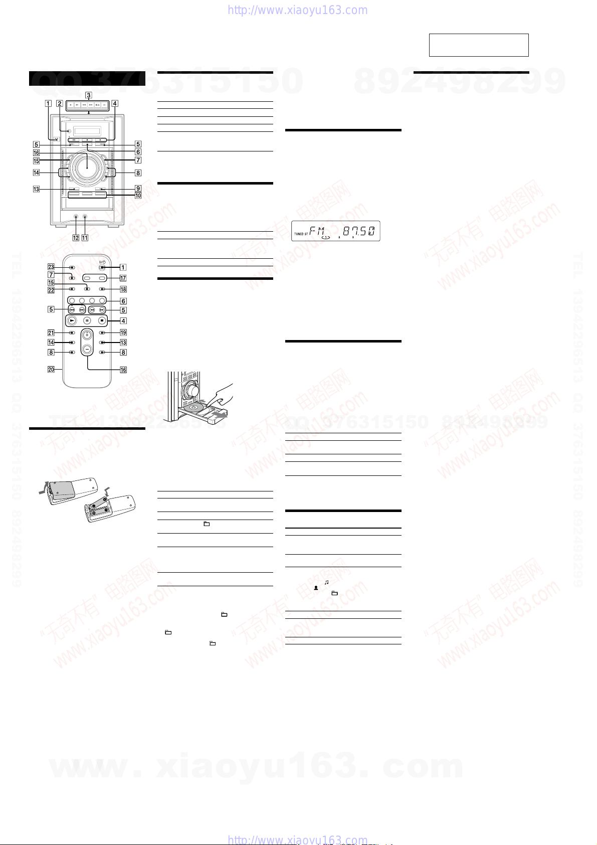
Playing a CD/MP3 disc
is manual mainly explains operations using the
remote, but the same operations can also be performed
using the buttons on the unit having the same or similar
names.
TEL
13942296513
Before using the system
To use the remote
Slide and remove the battery compartment lid , and
insert the two R6 (size AA) batteries (supplied), side
rst, matching the polarities shown below.
Notes on using the remote
With normal use, the batteries should last for about six months.
Do not mix an old battery with a new one or mix dierent types of
batteries.
If you do not use the remote for a long period of time, remove the
batteries to avoid damage from battery leakage and corrosion.
Batteries installed devices shall not be exposed to excessive heat such
as sunshine, re or the like.
To set the clock
1 Turn on the system.
Press (on/standby)
2 Select the clock set mode.
Press CLOCK/TIMER SET
ashes. If “PLAY SET” ashes, press /
repeatedly to select “CLOCK,” and then press ENTER
.
3 Set the time.
Press /
press ENTER
Use the same procedure to set the minutes.
Note
e clock settings are lost when you disconnect the power cord or if a
power failure occurs.
w
to turn on the system.
. e hour indication
repeatedly to set the hour, then
. e minute indication ashes.
w
w
.
1 Select the CD function.
Press CD (or FUNCTION repeatedly)
2 Place a disc.
Press (open/close)
disc with the label side up on the disc tray. To place
additional discs, slide the disc tray with your nger as
shown below.
To close the disc tray, press (open/close)
unit.
Do not force the disc tray closed with your nger, as
this may damage the unit.
3 Select a disc.
If the discs are currently stopped, press DISC SKIP
. To change discs while in other functions, press
DISC1–3
4 Start playback.
Press (play) (or CD (play) on the unit)
To exchange other discs during playback, press
EX-CHANGE
To Pr es s
Pause playb ack
Stop playback
Select a folder on an
MP3 disc
Select a track or le
Find a point in a
track or le
Select Repeat Play
To change the play mode
Press PLAY MODE repeatedly while the player is
stopped. You can select normal play (no display for all
discs or “1 DISC” for a disc or “
in the folder on the disc), shue play (“SHUF” for
all discs shue, “1 DISC SHUF” for one disc shue
SHUF*” for folder shue), or program play
or “
(“PGM”).
* When playing a CD-DA disc, (SHUF) Play performs the same
operation as 1 DISC (SHUF) Play.
Notes on Repeat Play
All tracks or les on a disc are played repeatedly up to ve times.
You cannot select “REP” and “SHUF” (all discs shue) at the same
time.
“REP1” indicates that a single track or le is repeated until you stop
it.
Notes on playing MP3 discs
Do not save other types of tracks or les or unnecessary folders on a
disc that has MP3 les.
Folders that have no MP3 les are skipped.
MP3 les are played back in the order that they are recorded onto
the disc.
e system can only play MP3 les that have a le extension of
“.MP3”.
If there are les on the disc that have the “.MP3” le extension,
but that are not MP3 les, the unit may produce noise or may
malfunction.
e maximum number of:
folders is 150 (including the root folder).
MP3 les is 255.
MP3 les and folders that can be contained on a single disc is 300.
folder levels (the tree structure of les) is eight.
on the unit.
on the unit.
(pause)
press the button again.
(stop)
(select folder) +/– .
/ (go back/go forward)
(or / on the unit)
Hold down / (rewind/fast
forward)
release the button at the desired
point.
REPEAT
“REP” or “REP1” appears.
xia
.
on the unit, and place a
. To resume play,
.
during playback, and
repeatedly until
” for all MP3 les
o
y
on the
device, and recording media cannot be guaranteed. Incompatible MP3
discs may produce noise or interrupted audio or may not play at all.
0
Notes on playing multisession discs
If the disc begins with a CD-DA (or MP3) session, it is recognized
as a CD-DA (or MP3) disc, and playback continues until another
session is encountered.
A disc with a mixed CD format is recognized as a CD-DA (audio)
disc.
.
Listening to the radio
1 Select “TUNER FM” or “TUNER AM.”
Press TUNER/BAND
2 Select the tuning mode.
Press TUNING MODE
appears.
3 Tune in the desired station.
Press +/– (or TUNING +/– on the unit)
Scanning stops automatically when a station is tuned
in, and then “TUNED” and “ST” (for stereo programs)
appear.
To stop automatic scanning
Press (stop) .
To tune in a station with a weak signal
If “TUNED” does not appear and the scanning does
not stop, press TUNING MODE
“MANUAL” appears, and then press +/– (or TUNING
+/– on the unit)
station.
To reduce static noise on a weak FM stereo
station
Press FM MODE repeatedly until “MONO” appears
to turn o stereo reception.
repeatedly to tune in the desired
Playing a tape (Except for the UK
model)
1 Select a tape function.
Press TAPE (or FUNCTION repeatedly)
2 Insert a tape.
Press (stop/eject)
tape into the cassette holder. Make sure there is no
slack in the tape to avoid damaging the tape or the
tape deck.
3 Start playback.
Press (play)
Q
To Pr es s
Pause playb ack
Stop playback
Rewind or fast
.
forward*
* Be sure to press (stop/eject) on the unit aer the tape has
been wound or rewound to the end.
Note
Do not turn o the system during playback or recording.
Q
on the unit.
7
3
(pause)
play, press the button again.
(stop/eject)
/
on the unit.
Changing the display
To Pr es s
Change
.
information on the
display*
Change Display
mode (See below.)
* For example, you can view CD/MP3 disc information, such as;
track or le number during normal play.
track or le name (“
artist name (“
album or folder name (“
total playing time while the player is stopped.
e system oers the following display modes.
Display mode When the system is o,
Power Saving
Mode
Clock
1)
You cannot set the clock in Power Saving Mode.
2)
e clock display automatically turns to Power Saving Mode aer
eight seconds.
Notes on the display information
Characters that cannot be displayed appear as “_”.
e following are not displayed;
total playing time for an MP3 disc.
remaining playing time for an MP3 le.
e following are not displayed correctly;
elapsed playing time of an MP3 le encoded using VBR (variable
bit rate).
folder and le names that do not follow either the ISO9660
Level 1, Level 2 or Joliet in the expansion format.
e following are displayed;
total playing time for a CD-DA disc when the play mode is
“1 DISC”.
remaining playing time for a track.
ID3 tag information for MP3 les when ID3 version 1 and
version 2 tags are used (ID3 version 2 tag information display has
priority when both ID3 version 1 and version 2 tags are used for a
single MP3 le).
up to 15 characters of ID3 tag information using uppercase letters
(A to Z), numbers (0 to 9), and symbols (‘< > * + , – / @ [ \ ] _).
u
1
DISPLAY
system is turned on.
DISPLAY
system is turned o.
”) during normal play.
”) during normal play.
e display is turned o to conserve
1)
power. e timer and clock continue
to operate.
2)
e clock is displayed.
6
3
repeatedly.
on the unit, and insert the
(rewind/fast forward)
”) during normal play.
9
8
repeatedly until “AUTO”
.
repeatedly until
.
5
1
3
6
on the unit. To resume
on the unit.
repeatedly when the
repeatedly when the
.
c
This section is extracted
from instruction manual.
Using optional audio components
4
2
To connect an optional headphones
Connect headphones to the PHONES jack on the
unit.
To connect an optional component
Connect additional audio source components to the
AUDIO IN jack
cord (not supplied). Tur n down the volume on the
system, and then select the AUDIO IN function.
0
5
1
o
9
on the unit using an analog audio
2
9
8
m
8
4
2
9
8
9
2
9
9
TEL 13942296513 QQ 376315150 892498299
9
6
HCD-EC68/EC78
Other Operations
7
Q
Q
TEL 13942296513 QQ 376315150 892498299
TEL
3
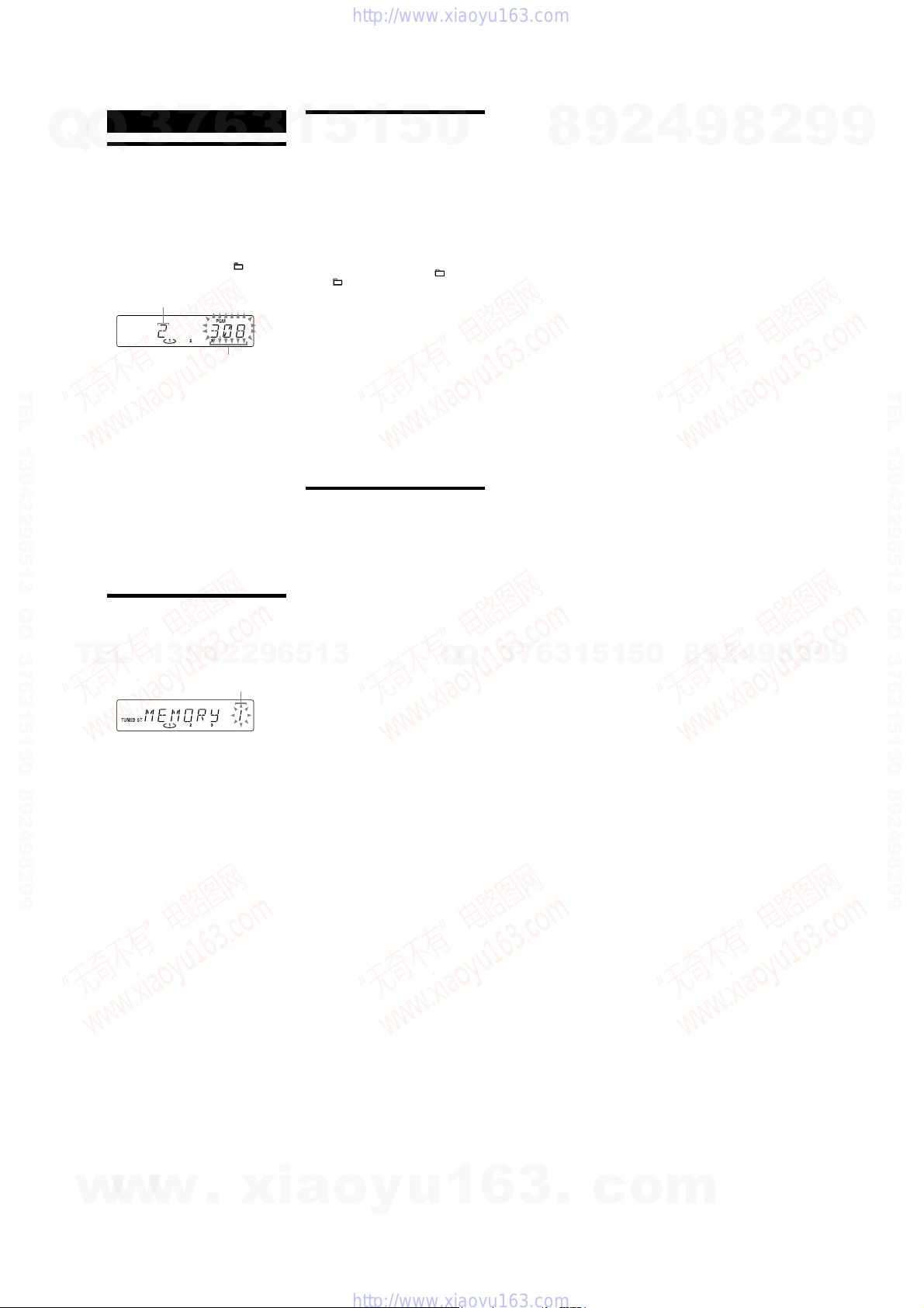
Creating your own CD program
(Program Play)
Use buttons on the remote to create your own program.
1 Press CD
2 Press PLAY MODE
3 Press DISC SKIP
4 Press / (or
5 Press ENTER
6 Repeat steps 3 through 5 to program additional
7 To play your program of tracks or les, press (or
To cancel Program Play
Press PLAY MODE repeatedly until “PGM”
disappears while the player is stopped.
To delete the last track or le of the program
Press CLEAR while the player is stopped.
To view program information, such as total
track number of the program
Press DISPLAY repeatedly.
Presetting radio stations
You can preset your favourite radio stations and tune
them in instantly by selecting the corresponding preset
number.
1 Tune in the desired station (See “Listening to the
2 Press TUNER MEMORY
3 Press +/– (or TUNING +/– on the unit)
4 Press ENTER
5 Repeat steps 1 through 4 to store other stations.
6 To call up a preset radio station, press TUNING
to select the CD function.
while the player is stopped.
repeatedly until the desired track number appears.
When programming MP3 les, press
repeatedly to select the desired folder, and then select
the desired le.
Selected track or le number
program.
tracks or les, up to a total of 25 tracks or les.
CD on the unit)
e program remains available until you open the disc
tray. To play the same program again, select the CD
function, and then press (or CD on the unit)
.
13942296513
radio”
)
.
to select your desired preset number.
If another station is already assigned to the selected
preset number, the station is replaced by the new
stations.
You can preset up to 20 FM and 10 AM stations. e
preset stations are retained for about half a day even
if you disconnect the power cord or if a power failure
occurs.
repeatedly until “PRESET” appears, and
MODE
then press +/– (or TUNING +/– on the unit)
repeatedly to select the desired preset number.
6
repeatedly until “PGM” appears
to select a disc.
on the unit)
/
+/–
Total playing time of the
selected track
to add the track or le to the
.
.
Preset number
repeatedly
.
3
Recording onto a tape (Except for the
UK model)
1
5
1
Use a TYPE I (normal) tape only.
You can record just the portions you like from a sound
source, including connected audio components.
Use buttons on the unit to control tape recording.
1 Insert a recordable tape into the cassette holder
with the side you want to record facing up.
2 Prepare the recording source.
Select the desired source to record.
Place the disc you want to record and press DISC
to select a disc.
SKIP
When recording a folder from an MP3 disc, press
PLAY MODE
+/– repeatedly to select the desired
press
folder.
To record only your favourite CD tracks or MP3
les in your desired order, perform steps 2 to 5 of
“Creating your own CD program.”
3 Start recording.
Press (record)
desired recording source.
e CD starts playing automatically aer 10 seconds
have passed.
If there is noise while recording from the tuner,
reposition the appropriate antenna to reduce the
noise.
While recording, you cannot listen to other sources.
To stop recording
Press .
Tip
We recommend that you press rst, and then press to
avoid noise being recorded when you stop recording.
Using the timers
e system oers two timer functions. If you use both
timers, the Sleep Timer has priority.
Use buttons on the remote to use the timer functions.
Sleep Timer:
You can fall asleep to music. is function works even if
the clock is not set.
Press SLEEP
system automatically turns o aer the current disc or
tape stops or in 100 minutes.
If the tape deck is still playing or recording at the set
time, the system turns o aer the tape deck stops.
Play Timer:
You can wake up to CD or tuner at a preset time.
Make sure you have set the clock.
1 Prepare the sound source.
Press VOLUME +/– (or turn VOLUME on the unit)
to adjust the volume.
To start from a specic CD track or MP3 le, create
your own CD program.
2 Press CLOCK/TIMER SET
3 Press /
then press ENTER
“ON TIME” appears, and the hour indication ashes.
4 Set the time to start playback.
Press /
press ENTER
e minute indication ashes. Use the procedure
above to set the minutes.
5 Use the same procedure as in step 4 to set the time
to stop playback.
6 Select the sound source.
Press /
you want appears, then press ENTER
shows the timer settings.
7 Press
If the system is on at the preset time, the Play Timer
will not play.
To activate or check the timer again
Press CLOCK/TIMER SELECT , press /
repeatedly until “PLAY SEL” appears, then press ENTER
.
To cancel the timer
Repeat the same procedure as above until “OFF” appears,
and then press ENTER
To change the setting
Start over from step 1.
Tip
e Play Timer setting remains as long as the setting is not cancelled
manually.
5
repeatedly to select “ ,” and then
, and then start playing the
repeatedly. If you select “AUTO,” the
.
repeatedly to select “PLAY SE T,”
.
repeatedly to set the hour, then
.
repeatedly until the sound source
to turn o the system.
.
0
Q
Q
. e display
7
3
8
6
3
9
1
5
2
1
5
4
0
9
8
9
8
2
4
2
9
8
9
2
9
9
TEL 13942296513 QQ 376315150 892498299
9
w
w
w
.
xia
o
y
u
1
6
3
.
c
o
m
7
HCD-EC68/EC78
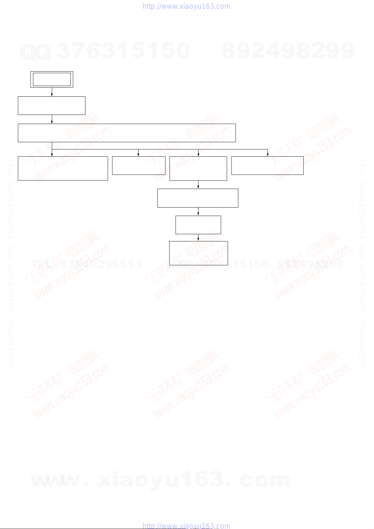
SECTION 3
DISASSEMBLY
• This set can be disassembled in the order shown below.
7
Q
Q
3-1. DISASSEMBLY FLOW
3-2. SIDE PANEL (L)/(R)
(Page 9)
3-3. TOP PANEL (EC68: UK MODEL)/TOP PANEL BLOCK (EXCEPT EC68: UK MODEL)
(Page 9)
3
SET
6
3
1
5
1
5
0
8
9
2
4
9
8
2
9
9
TEL 13942296513 QQ 376315150 892498299
3-4. TAPE MECHANISM DECK
(EXCEPT EC68: UK MODEL)
(Page 10)
TEL
13942296513
3-5. MAIN BOARD
(Page 10)
3-6. FRONT PANEL
SECTION
(Page 11)
3-8. CD MECHANISM BLOCK
(Page 12)
3-9. BU BLOCK
(Page 12)
3-11. OP BASE ASSY
(KSM-213D)
(Page 13)
7
3
Q
Q
3-7. BACK PANEL BLOCK
(Page 11)
5
1
5
1
3
6
0
8
9
2
4
9
8
2
9
TEL 13942296513 QQ 376315150 892498299
9
8
w
w
w
.
xia
o
y
u
1
6
3
.
c
o
m
Note: Follow the disassembly procedure in the numerical order shown below.
7
Q
Q
TEL 13942296513 QQ 376315150 892498299
3
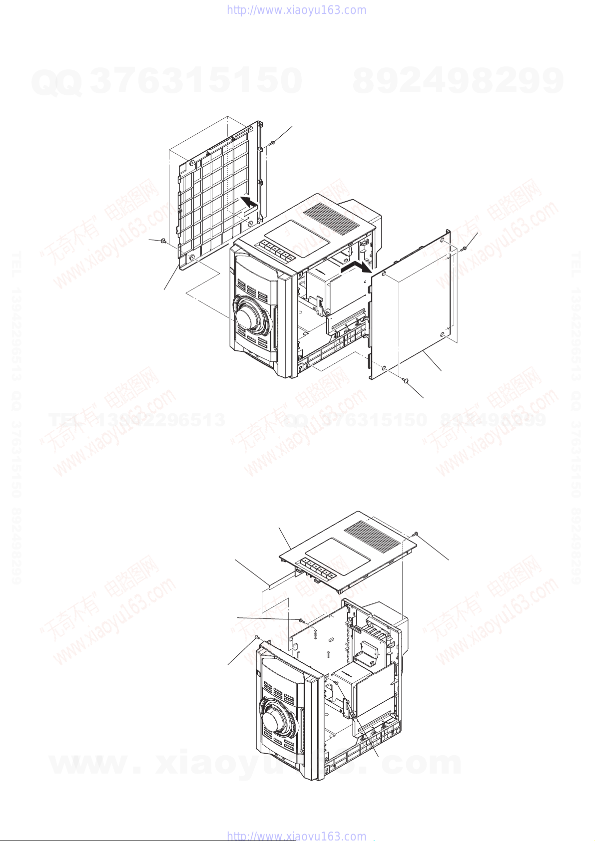
3-2. SIDE PANEL (L)/(R)
four screws
(case3 TP)
6
side panel (L)
3
1
5
1
5
0
two screws
(BVTP3 × 10)
8
9
2
4
HCD-EC68/EC78
2
9
8
two screws
(BVTP3 × 10)
9
9
TEL 13942296513 QQ 376315150 892498299
four screws
(case3 TP)
TEL
13942296513
3-3. TOP PANEL (EC68: UK MODEL)/TOP PANEL BLOCK (EXCEPT EC68: UK MODEL)
top panel (EC68: UK)
top panel block (except EC68: UK)
flexible flat cable (9 core)
(CN606) (except EC68: UK)
two screws
(BVTP3 × 10)
screw
(KTP3 × 10)
Q
Q
3
7
6
3
1
5
1
5
0
8
side panel (R)
8
9
4
2
9
two screws
(BVTP3 × 10)
2
9
9
w
w
w
.
xia
o
y
u
1
6
3
.
c
(KTP3 × 10)
screw
o
m
9
HCD-EC68/EC78
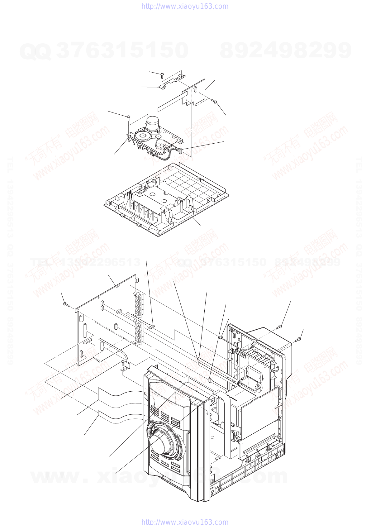
3-4. TAPE MECHANISM DECK (EXCEPT EC68: UK MODEL)
7
Q
Q
Note: This illustration is seeing top panel block from inside.
3
6
two screws
(2.6 × 8)
1
3
two screws
(2.6 × 8)
bracket (deck)
5
1
5
0
9
8
DECK board
two screws
(BVTP3 × 6)
connector (CN501)
2
4
9
8
2
9
9
TEL 13942296513 QQ 376315150 892498299
3-5. MAIN BOARD
TEL
two screws
RE
(BVTP3 × 6)
tape mechanism deck
(TCM-J1 or CS-21SC-900TP)
connector (CN151)
13942296513
MAIN board
RG
top panel block
3
Q
Q
flexible flat cable (5 core)
(CN603)
flexible flat cable (5 core)
(CN602) (EC78)
7
1
5
1
3
6
connector (CN633)
connector (CN601)
9
8
0
5
two screws
RT
(BVTP3 × 10) (EC78)
8
9
4
2
two screws
RB
(BVTP3 × 10)
2
9
TEL 13942296513 QQ 376315150 892498299
9
screw
(BVTP3 × 10)
flexible flat cable (27 core)
(CN607)
flexible flat cable (9 core)
(CN605)
flexible flat cable (21 core)
w
10
w
w
(CN608)
connector (CN604)
.
xia
o
y
u
1
6
3
.
c
o
m
Q
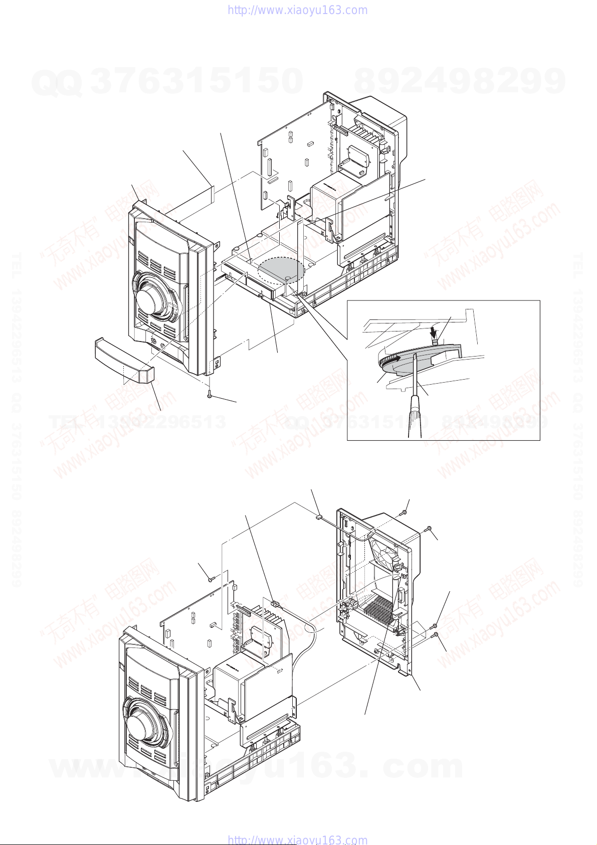
3-6. FRONT PANEL SECTION
7
Q
3
(CN607)
6
3
flexible flat cable (27 core)
front panel section
1
5
flexible flat cable
(9 core)
(CN605)
1
5
0
8
9
2
HCD-EC68/EC78
4
9
flexible flat cable (13 core)
(CN302)
8
2
9
9
TEL 13942296513 QQ 376315150 892498299
pull the tray by hand.
two screws
door (CD)
TEL
13942296513
3-7. BACK PANEL BLOCK
connector (power cord)
(CN053)
(BVTP3 × 10)
Q
connector (CN601)
Q
3
7
6
gear
5
1
5
1
3
two screws
(BVTP3 × 10) (EC78)
lever
Turn a gear by a driver
till a lever falls down
to the position of the figure.
0
8
9
2
4
9
8
2
9
TEL 13942296513 QQ 376315150 892498299
9
w
w
w
screw
(BVTP3 × 10)
.
xia
o
y
u
1
two screws
(BVTP3 × 10)
(BVTP3 × 10)
(BVTP3 × 10)
back panel block
Cut the clamp.
Note: Please do not forget fixation by clamping
when you install the power cord.
6
3
.
c
o
m
six screws
two screws
11
HCD-EC68/EC78
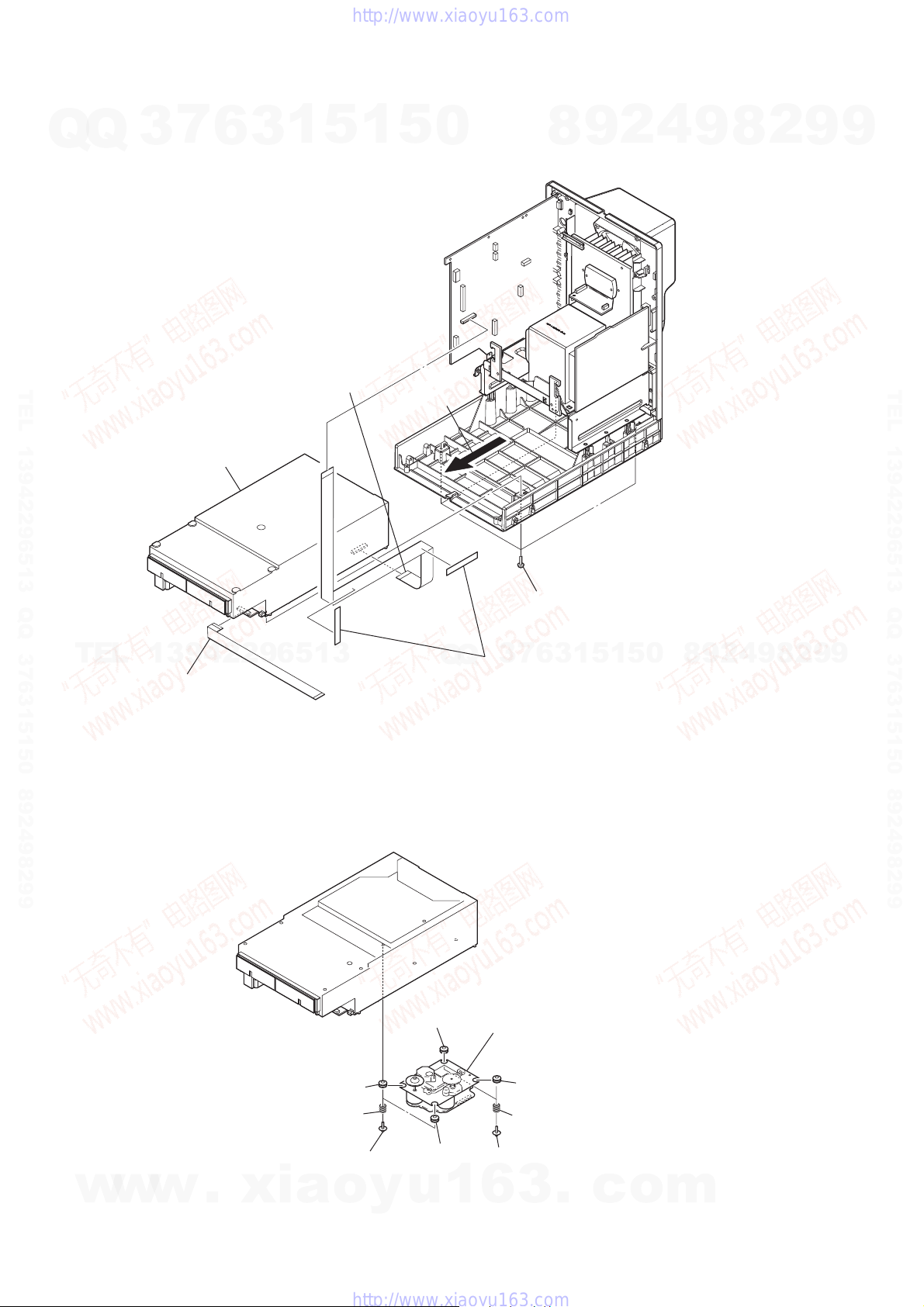
3-8. CD MECHANISM BLOCK
7
Q
Q
TEL 13942296513 QQ 376315150 892498299
3
CD mechanism block
6
1
5
3
flexible flat cable
(21 core)
(MAIN board: CN608/
CD board: CN201)
1
5
0
8
9
2
4
9
8
2
9
9
TEL 13942296513 QQ 376315150 892498299
TEL
3-9. BU BLOCK
13942296513
flexible flat cable (13 core)
insulator
Q
four screws
(BVTP3 × 10)
8
0
5
1
5
1
3
6
7
3
Q
two tapes
Note: When installing the CD mechanism section,
install two tapes for prevention of noise.
BU block
9
2
4
9
8
2
9
9
12
w
w
w
.
xia
insulator
two coil springs
(insurator)
two screws
(PTPWHM2.6)
(insurator)
insulator
o
y
u
1
two screws
(PTPWHM2.6)
6
3
insulator
two coil springs
.
c
o
m
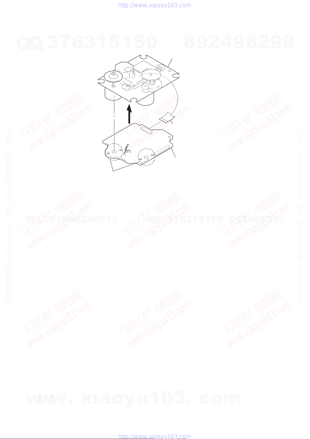
3-10. OP BASE ASSY (KSM-213D)
7
Q
Q
TEL 13942296513 QQ 376315150 892498299
3
6
3
1
5
1
5
0
op base assy
(KSM-213D)
flexible flat cable (16 core)
(CN301)
8
9
2
4
HCD-EC68/EC78
2
9
8
9
9
TEL 13942296513 QQ 376315150 892498299
TEL
Remove four solders.
13942296513
Q
Q
3
CD board
6
7
3
1
5
1
5
0
8
9
2
4
9
8
2
9
9
w
w
w
.
xia
o
y
u
1
6
3
.
c
o
m
13

HCD-EC68/EC78
SECTION 4
TEST MODE
COLD RESET
The cold reset clears all data including preset data stored in the
Q
Q
memory to initial conditions. Execute this mode when returning
the set to the customer.
Procedure:
1. In the standby status, press the [
on.
2. Press three buttons of [x], [FUNCTION] and at last [
multaneously.
3. When “RESET” appears, the set enters standby status.
PANEL TEST MODE
Enter The Panel Test Mode
Procedure:
1. In the standby status, press the [
TEL 13942296513 QQ 376315150 892498299
on.
2. Press three buttons of [DISPLAY], [x], and [FUNCTION] simultaneously.
3. When the panel test mode is activated, LEDs and segments of
the liquid crystal display are all turned on.
Version Check
Procedure:
1. In the panel test mode (all LEDs and segments of the liquid
crystal display are turned on), press the [FUNCTION] button.
2. On the liquid crystal display, date and version are displayed
“xxxxxxxx”. For example, “1114V102”.
3. From this status, press the [X] button, and the destination and
model name are displayed. For example, “CE2” and “ESLO–
”
4. To release from this mode, press three buttons of [DISPLAY],
[
], and [FUNCTION] simultaneously.
x
TEL
Key Test Mode
Procedure:
1. In the panel test mode (all LEDs and segments of the liquid
crystal display are turned on), press the [DISPLAY] button.
2. The message “KEY0 0 0”displayed. Whenever any buttons
are pressed and the [VOLUME] dial is turned, the value is
changed.
3. To release from this mode, press three buttons of [DISPLAY],
[
], and [FUNCTION] simultaneously.
x
CD REPEAT 5 LIMIT CANCEL MODE
Number of repeats for CD playback is 5 times when the repeat
mode is “REPEAT”. This mode enables CD to repeat playback for
limitless times.
Procedure:
1. Press the [
2. Press the [FUNCTION] button to select CD function.
3. Press three buttons of [DISPLAY], [
ING] simultaneously.
4. It enters the CD repeat 5 limit cancel mode and displays “NO
LIMIT”
5. To release this mode, press the [
CD SHIP MODE
This mode can run the CD sled motor optionally. Use this mode,
for instance, when cleaning the optical pick-up.
Procedure:
1. Press the [
2. Confi rm there is no disc in all trays.
3. Press the [FUNCTION] button to select CD function.
4. Press two buttons of [CD N] and [
w
5. Set to the CD ship mode. (chucking on)
6. After blink “STANDBY”, “LOCK” is displayed, disconnect
the AC plug.
I/1
I/1
w
3
7
6
1
3
] button to turn the power
I/1
] button to turn the power
I/1
13942296513
] button to turn the power on.
], and [
x
] button to turn the power off.
I/1
] button to turn the power on.
w
.
xia
l m
] simultaneously.
I/1
5
o
1
I/1
– TUN-
y
5
] si-
CD TRAY LOCK
This mode is for the antitheft of CD disc in shop. (not for trans-
0
port)
Procedure:
1. Press the [
2. Press the [FUNCTION] button to select CD function.
3. Insert a disc.
4. While pressing the [
seconds.
5. The message “LOCKED” is displayed and the disc tray is
locked. (Even if exiting from this mode, the disc tray is still
locked)
6. If press the [Z] button to eject the disc, the message “LOCKED”
is displayed and can not eject the disc.
7. To release this lock, while pressing the [
[
Z
8. The message “UNLOCKED” is displayed and the disc tray is
unlocked.
CD POWER MANAGE
This mode is for switch the CD power supply on/off. Even if this
state pulls out AC plug, it is held.
Procedure:
1. Press the [
2. Press the [FUNCTION] button to select CD function.
3. Press the [
4. After pressing the [DISPLAY] button, while pressing the [
button, press the [
5. It turns power on and display “CD POWER”, then display
“ON” or “OFF”.
CHANGE-OVER THE AM TUNING INTERVAL
(Except EC68: AEP, UK and Russian/EC78: AEP and
Q
Q
Russian models)
The AM tuning interval can be changed over 9 kHz or 10 kHz.
Procedure:
1. Press the [
2. Press the [TUNER/BAND] button to select TUNER (AM)
function.
3. Press the [
4. After pressing the [DISPLAY] button, while pressing the
[TUNING +
5. It turns power on and display “9k STEP” or “10k STEP”, and
thus the tuning interval is changed over.
CD SHIP AND COLD RESET
Procedure:
1. Press the [
2. Confi rm there is no disc in all trays.
3. Press the [FUNCTION] button to select CD function.
4. Press three buttons of [PLAY MODE/TUNING MODE],
[
l m
5. After blink “STANDBY”, “RESET” is displayed, disconnect
the AC plug.
COMMON TEST MODE
Procedure:
1. Press the [
2. Press three buttons of [PLAY MODE/TUNING MODE],
[TUNING +
3. It enters the common test mode and displays “COMMON”.
4. Each time the [VOLUME] dial is turned, “VOL MIN”, “VOL
16”, and “VOL MAX” are displayed
5. To release from this mode, press three buttons of [PLAY
u
1
6
MODE/TUNING MODE], [TUNING +
PLAY] simultaneously.
I/1
] button for 5 seconds again.
I/1
I/1
7
3
I/1
I/1
I/1
– TUNING] and [
I/1
3
4
2
9
8
] button to turn the power on.
] button, press the [Z] button for more 5
x
] button to turn the power on.
] button again to turn the power off (standby).
] button.
I/1
8
0
5
1
5
1
3
6
] button to turn the power on.
] button again to turn the power off (standby).
M L
] button to turn the power on.
] button to turn the power on.
M L
] button, press the [
] simultaneously.
I/1
], and [DISPLAY] simultaneously.
.
c
o
m
8
9
] button, press the
x
9
4
2
9
] button.
I/1
M L
], and [DIS-
2
8
9
x
2
]
9
9
TEL 13942296513 QQ 376315150 892498299
9
14
HCD-EC68/EC78
[CD SERVO TEST MODE]
Q
TEL 13942296513 QQ 376315150 892498299
This mode can check the servo system operations of the optical
Q
pick-up system (= optical unit + CD board).
Note1: Do not enter the [CD SERVO TEST MODE] while any other test
Note2: Do not enter any other test mode while the [CD SERVO TEST
How to Enter the CD Servo Test Mode
Procedure:
1. Press the [
2. Press the [FUNCTION] button to select CD function.
3. Press three buttons of [CD N], [
[DISPLAY] simultaneously.
4. It enters the CD servo test mode and displays “BDT S CU”.
How to Exit from the CD Servo Test Mode
Procedure:
1. Press three buttons of [CD N], [
[DISPLAY] simultaneously.
2. It releases from the CD Servo Test Mode and returns to the
ordinary CD function.
Key Operation:
[
+], [ –]:
Use these keys to move between the fi ve modes
TEL
[DSGX] , [EQ]:
Use these keys to move between the different layers
[TUNING +
Use these keys to move the cursor to the right digit
Press [TUNING +
7
3
mode is in progress.
MODE] is in progress.
13942296513
6
] button to turn the power on.
I/1
contained in the CD Servo Test Mode, that are the
S-Curve Mode, the RAM Read Mode, the RAM
Write Mode, the Command Out Mode and the Error
Rate Mode as described below. Also, use these keys
to move between the menus within the respective
fi ve modes. When [
vances to the next menu or to the next mode. When
[ –] is pressed, the screen returns back to the
previous menu or to the previous mode. Use these
keys also to increase or decrease the numeric value
when changing the numeric value. Pressing [ +]
increases the value and pressing [ –] decreases
the value.
of the hierarchy of the CD Servo Test Mode shown
below. Press [DSGX] to move down to the lower
layer, and press [EQ] to move up to the higher layer.
M L
], [
or to the left digit in the six-digit number, when
changing the numeric value.
to the right, and press [
return the cursor to the left.
1
3
l m
+] is pressed, the screen ad-
– TUNING]:
M L
5
1
l m
l m
l m
– TUNING] and
– TUNING] and
] to move the cursor
– TUNING] to
5
0
Q
Q
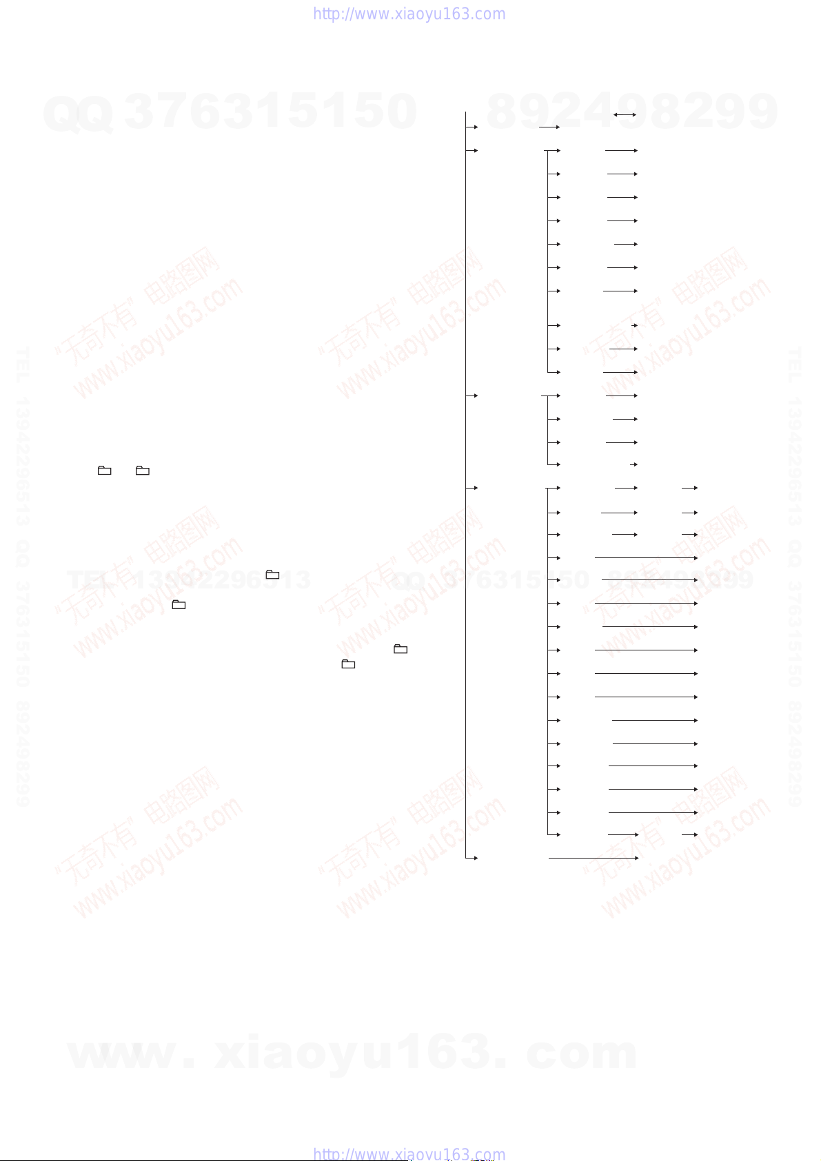
CD Servo Test Mode Tree:
S Curve Mode LD ON
(BDT S CU) (LD ON)
(BDTRAM R) (DISCTYPE) (AL: 0000, RW: 0001)
Gain Index value indication
(GAININDX) (0001)
RFO GAIN value indication
(RFO_GAIN) (0009)
FEO GAIN value indication
(FEO_GAIN) (0005)
SBAD GAIN value indication
(SBAD_GAI) (0007)
TEO GAIN value indication
(TEO_GAIN) (000A)
Disc Size value indication
(DISCSIZE) (0000: Non disc, 0001: 8cm,
0002: 12cm)
(OPABRKER) (0000)
SBBT Data value indication
(SBBT DAT) (006C)
FEOOCD value indication
(FEOOCD) (0440)
(BDTRAM W) (00 SPG) (Non mask:00, Mask:01)
Fix RF Gain value edit
(00 FIX) (Non Fix:00, AL Fix:01, RW Fix:02)
TMAX ON value edit
(00 TMA)
Driver Mute OFF value edit
(00 D_M) (Normal:00, Forced OFF:01)
(BDT COMO) (COMOUT6X) (000000) (OK)
READ2X value edit command out
(READ2X) (60) (50)
REG READ value edit command out
(REG_READ) (00) (0000)
FEBC? command out
(FEBC?) (00)
FGADD? command out
7
3
(FGADD?) (10)
TEBC? command out
(TEBC?) (00)
TGADD? command out
(TGADD?) (00)
RFGC? command out
(RFGC?) (00)
FEOF? command out
(FEOF?) (FFC0)
TEOF? command out
(TEOF?) (FFC0)
TEIOCD1? command out
(TEIOCD1?) (FE80)
TEIOCD2? command out
(TEIOCD2?) (FF40)
TEIOCD3? command out
(TEIOCD3?) (FFC0)
TEOOCD? command out
(TEOOCD?) (FD00)
FEOOCD? command out
(FEOOCD?) (F780)
MONITOR value edit command out
(MONITOR) (570A00) (OK)
Error Rate Mode Error rate indication
(BDT ERR) (00000000)
9
8
RAM Read Mode
RAM Write Mode
Command Out Mode
3
6
Disc Type value indication
SPG Mask value edit
COMOUT6X value edit command out
1
5
1
Higher layer Lower layer of menu hierarchy
4
2
Op ABRAKE Error
0
5
9
value indication
2
9
8
8
4
2
9
8
9
2
9
9
TEL 13942296513 QQ 376315150 892498299
9
[FUNCTION]:
Use this key to execute Command Out in the Com-
mand Out Mode.
w
w
w
.
xia
o
y
u
1
6
3
.
c
o
m
15

HCD-EC68/EC78
CD SERVICE MODE
This mode can move the SLED of the optical pick-up, and also can
Q
Q
turn the optical pick-up laser power on and off.
Procedure:
1. Press the [
2. Press three buttons of [CD N], [TUNING +
DISPLAY simultaneously.
3. Press the [FUNCTION] button to select CD function.
4. It enters the CD service mode and displays “SERVICE”.
5. To exit from this mode, press three buttons of [CD N], [TUN-
ING +
Key Operation:
[TUNING +
Use these keys to move the SLED. When [TUN-
TEL 13942296513 QQ 376315150 892498299
When [
[DISPLAY]:
Use this key to turn the optical pick-up laser power
CD ERROR CODE
The past errors of the CD mechanism (CDM) are displayed as the
CDM Errors, and those of the optical pick-up system (= optical
unit + CD board) are displayed as the BD Errors as shown below.
TEL
Procedure:
1. Press the [
2. Press the [FUNCTION] button to select CD function.
3. Press three buttons of [TUNING +
PLAY] simultaneously.
4. Then, the CDM error code is displayed as “M0xxxxxx” (x
means hexadecimal number) on the liquid crystal display as
shown below.
5. Every pressing of the [TUNING +
mode increments the number after “M” starting from “M0” up
to “M9”, and then returns to “M0”. Every pressing of the [
m
after “M”. The smaller the error code number is, the newer the
error content is.
6. When the [PLAY MODE/TUNING MODE] button is pressed
then, the BD error code is displayed as “D0xxxxxx” (x means
hexadecimal number) on the liquid crystal display as shown
below. In the same way as the CDM error code, use of the
[TUNING +
tons in this mode enables tracing of the error history.
7. To release from this mode, press the [
power off.
I/1
M L
M L
ING +
moves to outer circumference and the message
“SLED OUT” is displayed.
mode, the SLED moves to inner circumference and
the message “SLED IN” is displayed.
on and off. When the laser power is turned on, the
message “LD ON” is displayed. When the laser
power is turned off, the message “LD OFF” is displayed.
I/1
– TUNING] button in this mode decrements the number
7
3
] button to turn the power on.
] and DISPLAY simultaneously.
], [
l m
M L
l m
6
] is pressed in this mode, the SLED
– TUNING] is pressed in this
1
3
– TUNING]:
13942296513
] button to turn the power on.
M L
M L
M L
] and the [
l m
I/1
– TUNING] but-
] button to turn the
5
1
5
M L
], [x] and [DIS-
] button in this
], and
l
Contents of “CDM Errors”
Error display example
0
M 0 FF 11 42
1 2 3 4
1 It indicates the error history number
0 to 9: The error code number 0 indicates the newest error.
2 It indicates whether the CDM error occurs in the normal opera-
tions or during the initialization operation.
FF : The error has occurred in the normal opera-
Other than FF : The error has occurred during the initialization
3 It indicates the processing during which the trouble has oc-
curred.
01: The disc EJECT processing is in progress.
02: The disc INSERTION-WAITING processing is in prog-
ress.
03: Processing of the disc INSERTION-REQUEST for the up-
per CD tray is in progress.
04: Processing of the disc EJECTION-REQUEST for the up-
per CD tray is in progress.
05: The disc pulling-in operation is in progress.
06: The disc chucking processing is in progress.
07: The disc re-chucking processing is in progress.
08: The disc chucking-release completion operation is in prog-
ress.
4 It indicates the operation during which the trouble has oc-
curred.
00 : Waiting for the operation.
7
3
Q
Q
10 to 13 : The disc EJECT operation is in progress.
20 : The disc pulling-in operation is in progress.
30 : The disc chucking-release operation is in progress.
40 to 43 : The disc EJECT operation due to error is in prog-
ress.
Contents of “BD Errors”
Error display example
0 02 09
D
1 2 3 4
1 It indicates the error history number
0 to 9: The error code number 0 indicates the newest error.
2 It indicates the error content
01: The focus servo cannot lock-in.
02: GFS is no good (NG).
03: The startup time exceeds the specifi ed period of time (time
over)
04: The focus servo is unlocked continuously.
05: Q code cannot be obtained within the specifi ed period of
time.
06: The tracking servo cannot lock-in.
07: Blank disc
8
6
3
01
9
tions.
operation.
5
1
2
1
5
4
0
9
8
9
8
2
4
2
9
8
9
2
9
9
TEL 13942296513 QQ 376315150 892498299
9
16
w
w
w
.
xia
o
y
u
1
6
3
.
c
o
m
HCD-EC68/EC78
3 It indicates the on-going processing of optical pick-up system
Q
TEL 13942296513 QQ 376315150 892498299
(= optical unit + BD board) when the trouble has occurred.
Q
01: The CD SHIP mode processing is in progress.
02: The POWER OFF processing is in progress.
03: The INITIALIZE processing is in progress.
04: The optical pick-up system (= optical unit + BD board) is
05: The STOP operation is in progress.
06: The startup processing is in progress.
07: The TOC read-in processing is in progress.
08: The SEARCH operation is in progress.
09: The PLAY operation is in progress.
0A: The PAUSE operation is in progress.
0B: The PLAY – MANUAL SEARCH operation is in prog-
0C: The PAUSE – MANUAL SEARCH operation is in prog-
4 It indicates the operation that is being processed when the trou-
ble has occurred.
It indicates the step number of each processing specifi ed by 3.
Because the numbers of steps are different in each processing,
this number is different in each processing.
CD FACTORY MODE
Note1: Do not enter the [CD FACTORY MODE] while any other test-
Note2: Do not enter any other test mode while the [CD FACTORY
7
3
in the stop state.
ress.
ress.
mode is in progress.
MODE] is in progress.
6
3
1
5
1
5
0
Key Operation:
[DISPLAY]:
The display changes in the following order when-
[DSGX]:
RF gain setting changes whenever the button is
“–”: No gain fi xation.
“AL”: Fix to the gain for AL disc.
“RW”: Fix to the gain for RW disc.
[EQ]:
Tracking servo setting changes whenever the but-
“ON”: Tracking servo ON.
“OFF”: Tracking servo OFF.
[FUNCTION]:
S character mode setting changes whenever the but-
“ ”: S character mode OFF.
“S”: S character mode ON.
8
4
2
9
ever the button is pressed.
(Initial display)
fcsAG ** (**: Focus AGC value)
trkAG ** (**: Track AGC value)
RF-AG ** (**: RF AGC value)
pressed.
ton is pressed.
ton is pressed.
9
8
2
9
9
TEL 13942296513 QQ 376315150 892498299
Procedure:
1. Press the [
TEL
13942296513
2. Press the [FUNCTION] button to select CD function
3. Press three buttons of [CD N], [FUNCTION], and [DIS-
PLAY] simultaneously.
4. It enters the CD factory mode and displays the following message.
–X1ON
S character mode setting
Tracking servo setting
RF gain setting
] button to turn the power on.
I/1
Q
Q
5. To release from this mode, press the [
3
power off.
6
7
3
1
5
1
5
0
8
9
2
] button to turn the
I/1
2
8
9
4
9
9
w
w
w
.
xia
o
y
u
1
6
3
.
c
o
m
17
HCD-EC68/EC78
SECTION 5
MECHANICAL ADJUSTMENTS
SECTION 6
ELECTRICAL ADJUSTMENTS
PRECAUTION
1. Clean the following parts with a denatured-alcohol-moistened
Q
Q
swab :
record/playback head pinch roller
erase head rubber belts
capstan idlers
2. Demagnetize the record/playback head with a head demag-
netizer. (Do not bring the head magnetizer close to the erase
head.)
3. Do not use a magnetized screwdriver for the adjustments.
4. After the adjustments, appiy suitable locking compound to the
parts adjusted.
5. The adjustments should be performed with the rated power
supply voltage unless otherwise noted.
• Torque Measurement
TEL 13942296513 QQ 376315150 892498299
Mode Torque Meter Meter Reading
FWD CQ-102AS
FWD
Back Tension
FF CQ-201AS
REV CQ-201B
3
7
6
CQ-102C
1
3
(0.28 – 1.12 oz • inch)
(0.021 – 0.083 oz • inch)
5
2.0 – 8.0 mN • m
(20 to 80 g • cm)
0.15 – 0.6 mN • m
(1.5 to 6 g • cm)
5 – 17.7 mN • m
(50 to 177 g • cm)
(0.7 – 2.48 oz • inch)
5 – 17.7 mN • m
(50 to 177 g • cm)
(0.7 – 2.48 oz • inch)
1
5
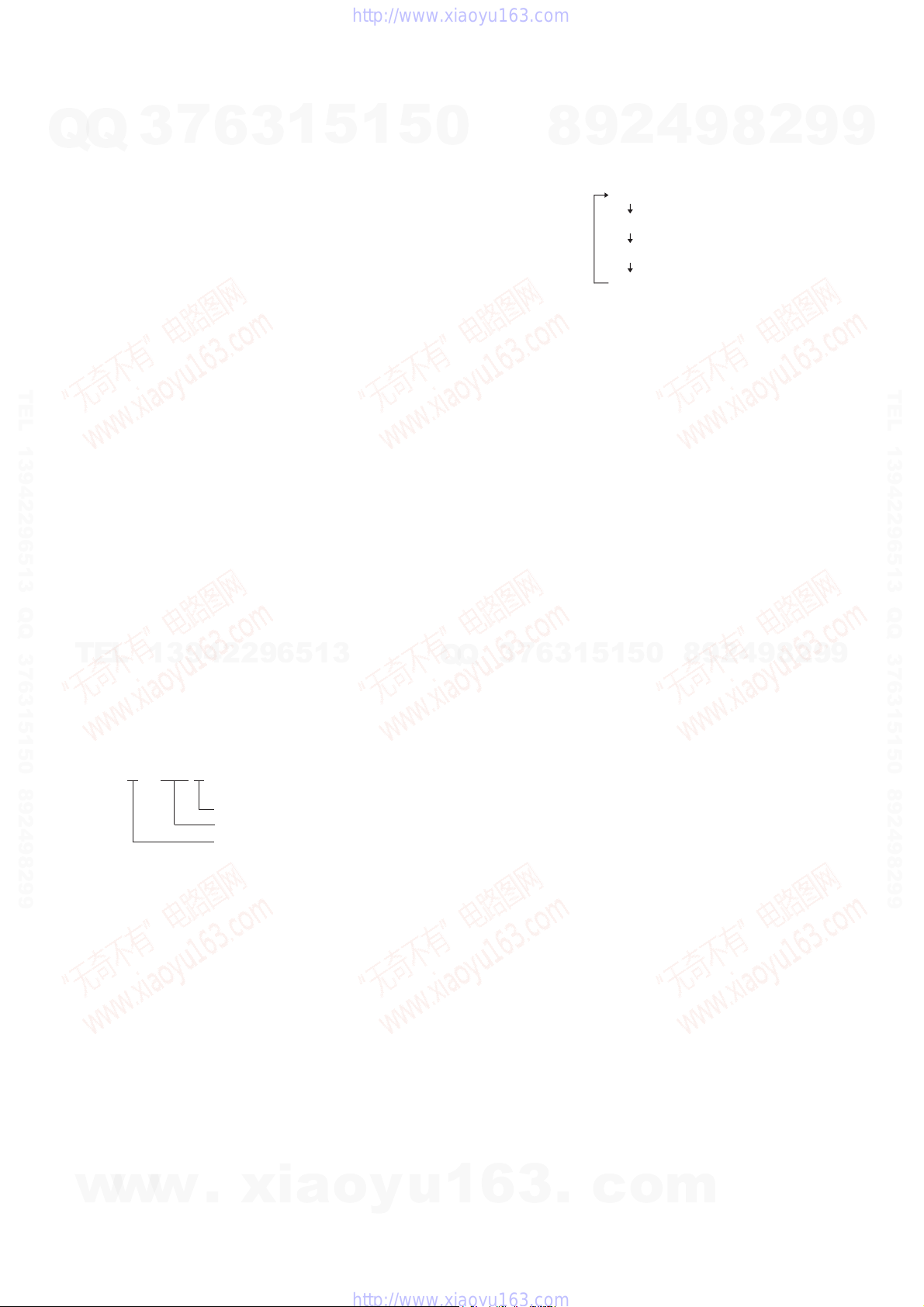
DECK SECTION (EXCEPT EC68: UK model) 0 dB = 0.775V
0
1. Demagnetize the record/playback head with a head demagnetizer.
2. Do not use a magnetized screwdriver for the adjustments.
TEST TAPE
Tape Signal Used for
P-4-A063 6.3 kHz, -10 dB Azimuth Adjustment
RECORD/PLAYBACK HEAD AZIMUTH ADJUSTMENT
Note: Perform this adjustments for both decks.
Procedure:
1. Mode: Playback
test tape
P-4-A063
(6.3 kHz, −10 dB)
2. Turn the adjustment screw and check output peaks. If the peaks
do not match for L-CH and R-CH, turn the adjustment screw
so that outputs match within 1dB of peak.
8
set
2
9
JACK board
PHONES jack
(J492)
4
level meter
+
–
9
8
2
9
9
TEL 13942296513 QQ 376315150 892498299
• Tape Tension Measurement
Mode Tension Meter Meter Reading
TEL
FWD CQ-403A
13942296513
(more than 2.82 oz)
more than 80 g
L-CH
7
3
Q
Q
peak
R-CH
Screw
position
3. Mode: Playback
test tape
P-4-A063
(6.3 kHz, −10 dB)
peak
set
waveform of oscilloscope
1
3
6
Output
level
JACK board
PHONES jack
(J492)
within
1
5
1dB
5
L-CH
peak
8
0
R-CH
peak
oscilloscope
V
9
H
2
4
within
1dB
Screw
position
9
8
2
9
9
18
w
w
w
.
xia
in phase 45° 90° 135° 180°
4. After the adjustments, apply suitable locking compound to the
pats adjusted.
o
y
u
1
6
3
good
.
c
wrong
o
m

HCD-EC68/EC78
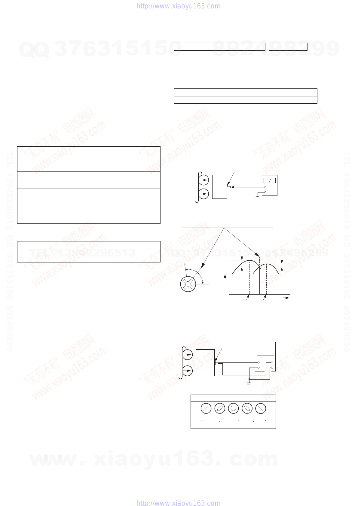
Adjustment Location: Record/Playback/Erase Head
7
Q
Q
TEL 13942296513 QQ 376315150 892498299
3
6
3
1
5
1
5
0
CD SECTION
Note:
1. CD Block is basically constructed to operate without adjustment.
2. Use YEDS-18 disc (3-702-101-01) unless otherwise indicated.
3. Use an oscilloscope with more than 10 MΩ impedance.
4. Clean the object lens by an applicator with neutral detergent when the
signal level is low than specifi ed value with the following checks.
5. Check the focus bias check when optical pick-up block is replaced.
FOCUS BIAS CHECK
CD board
TP121 (RFI)
TP124 (VC)
Procedure :
1. Connect the oscilloscope to TP121 (RFI) and TP124 (VC) on
the CD board.
2. Press the [I/1] button to turn the power ON, and press the [Z]
button to open the CD disc tray.
3. Set disc (YEDS-18) on the trey and press the [CD N] button
to playback.
4. Confi rm that oscilloscope waveform is as shown in the fi gure
below. (eye pattern)
A good eye pattern means that the diamond shape (◊) in the
center of the waveform can be clearly distinguished.
8
9
4
2
oscilloscope
(DC range)
+
–
9
2
8
VOLT/DIV: 200 mV
TIME/DIV: 500 ns
9
9
TEL 13942296513 QQ 376315150 892498299
TEL
13942296513
Q
Q
0
5
1
5
1
3
6
7
3
Checking Location:
– CD Board (Conductor Side) –
TP124
(VC)
TP121
(RFI)
IC101
8
9
4
2
level:
1.2 ± 0.3 Vp-p
9
8
2
9
9
w
w
w
.
xia
o
y
u
1
6
3
.
c
o
m
19
 Loading...