

Sony HCD-BX5, HCD-DX5, HCD-DX5J Service manual
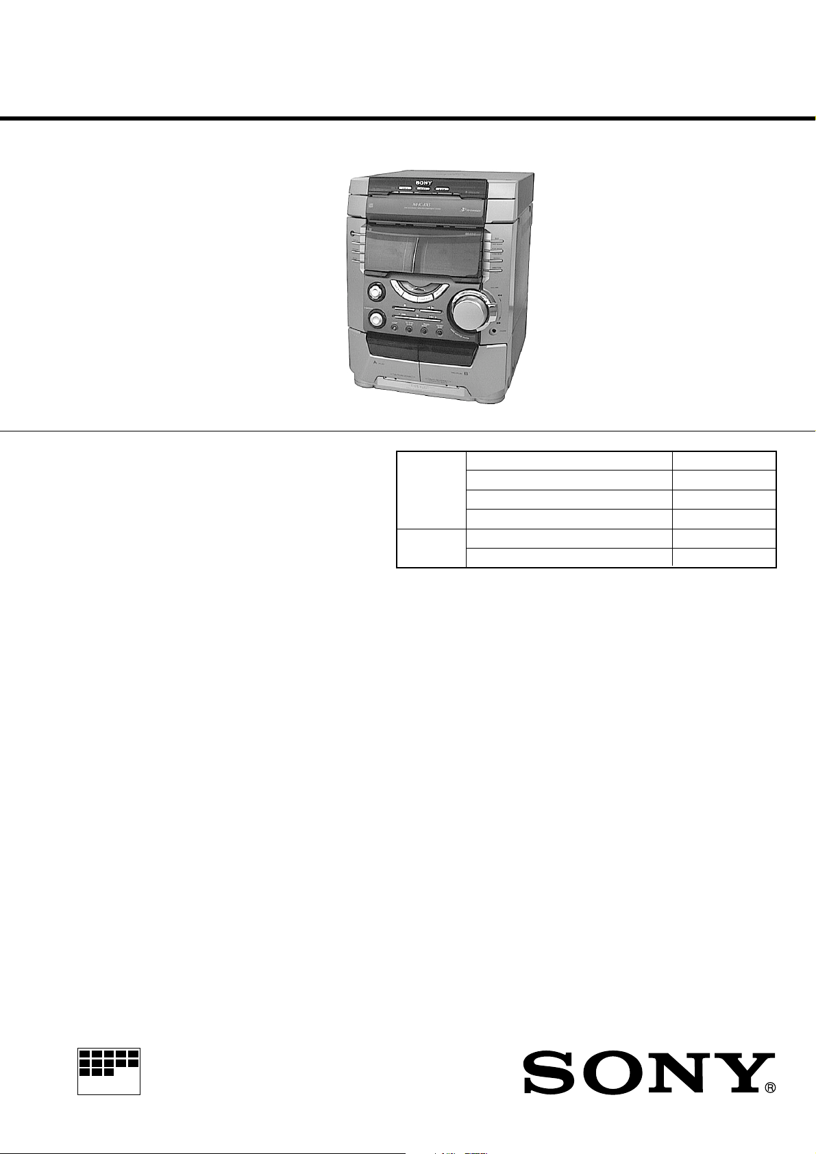
HCD-BX5/DX5/DX5J
SERVICE MANUAL
Ver 1.0 2000.1
• HCD-BX5/DX5/DX5J is the tuner,
deck, CD and amplifier section in
MHC-BX5/DX5/DX5J.
Photo: HCD-BX5
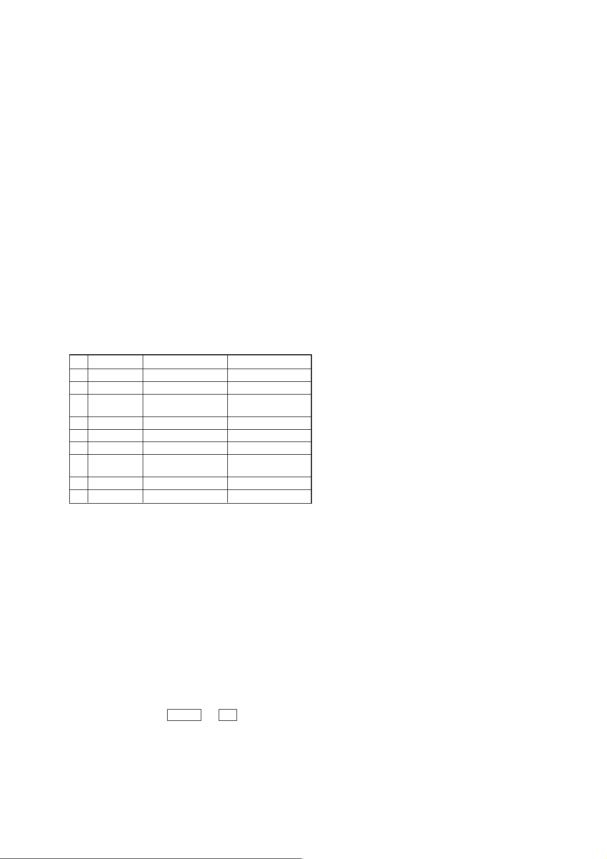
CD CD Mechanism Type CDM58-K2BD38
Section Base Unit Name BU-K2BD38
Tape deck Model Name Using Similar Mechanism NEW
Section T ape Transport Mechanism T ype TCM-230MWR11
US Model
Canadian Model
AEP Model
UK Model
HCD-BX5
E Model
Australian Model
HCD-DX5/DX5J
Model Name Using Similar Mechanism NEW
Optical Pick-up Name KSM-213DAP
SPECIFICATIONS
AUDIO POWER SPECIFICATIONS:
(HCD-BX5 US model only)
POWER OUTPUT AND TOTAL
HARMONIC DISTORTION:
with 6 ohm loads both channels driven, from 120-10,000 Hz; rates
95 watts per channel minimum RMS power, with no more than 10%
total harmonic distortion from 250 milliwatts to rated output.
Amplifier section
US, Canadian model:
HCD-BX5:
Continuous RMS power output (reference)
80 + 80 watts
(6 ohms at 1 kHz, 10% THD)
Total harmonic distortion less than 0.07%
(6 ohms at 1 kHz, 50 W)
AEP, UK model:
HCD-BX5:
DIN power output (rated) 80 + 80 watts
(6 ohms at 1 kHz, DIN)
Continuous RMS power output (reference)
100 + 100 watts
(6 ohms at 1 kHz, 10% THD)
Music power output (reference)
170 + 170 watts
(6 ohms at 1 kHz, 10% THD)
Other model:
HCD-DX5:
The following measured at AC 120, 220, 240 V 50/60 Hz
DIN power output (rated) 95 + 95 watts
(6 ohms at 1 kHz, DIN)
Continuous RMS power output (reference)
125 + 125 watts
(6 ohms at 1 kHz, 10% THD)
Inputs
MD/VIDEO IN: voltage 450/250 mV,
(phono jacks) impedance 47 kilohms
MIC: sensitivity 1 mV,
(mini jack) impedance 10 kilohms
Outputs
PHONES: accepts headphones of
(stereo mini jack) 8 ohms or more
SPEAKER: accepts impedance of 6 to 16 ohms
CD player section
System Compact disc and digital audio system
Laser Semiconductor laser (λ=780 nm)
Emission duration: continuous
Laser output Max. 44.6 µW*
*This output is the value measured at a
distance of 200 mm from the objective
lens surface on the Optical Pick-up Block
with 7 mm aperture.
— Continued on next page —
COMPACT DISC DECK RECEIVER
MICROFILM
Wavelength 780 – 790 nm
Frequency response 2 Hz – 20 kHz (±0.5 dB)
Signal-to-noise ratio More than 90 dB
Dynamic range More than 90 dB
CD OPTICAL DIGITAL OUT
(Square optical connector jack, rear panel)
Wavelength 660 nm
Output Level –18 dBm
Tape player section
Recording system 4-track 2-channel stereo
Frequency response 40 – 13,000 Hz (±3 dB), using Sony TYPE I
cassette
Dimensions (w/h/d) Approx. 280 x 360 x 425 mm
Mass
US model:
HCD-DX5: Approx. 9.5 kg
HCD-BX5: Approx. 8.6 kg
Design and specifications are subject to change without notice.
Tuner section
FM stereo, FM/AM superheterodyne tuner
FM tuner section
Tuning range 87.5 – 108.0 MHz
Antenna FM lead antenna
Antenna terminals 75 ohm unbalanced
Intermediate frequency 10.7 MHz
AM tuner section
Tuning range
US, Canadian, Mexican, Argentina models:
530 – 1,710 kHz
(with the interval set at 10 kHz)
531 – 1,710 kHz
(with the interval set at 9 kHz)
AEP, Saudi Arabia models:
531 – 1,602 kHz
(with the interval set at 9 kHz)
Other models: 531 – 1,602 kHz
(with the interval set at 9 kHz)
530 – 1,710 kHz
(with the interval set at 10 kHz)
Antenna AM loop antenna
Antenna terminals External antenna terminal
Intermediate frequency 450 kHz
General
Power requirements
US, Canadian models: 120 V AC, 60 Hz
AEP, UK model: 230 V AC, 50/60 Hz
Australian model: 230-240 V AC, 50/60 Hz
Mexican model: 120 V AC, 50/60 Hz
Thailand model: 220 V AC, 50/60 Hz
Other models: 120 V, 220 V or 230 - 240 V AC, 50/60 Hz
Adjustable with voltage selector
Power consumption
US model:
HCD-BX5: 160 watts
Canadian model:
HCD-BX5: 150 watts
AEP, UK model:
HCD-BX5: 190 watts
Other models:
HCD-DX5: 230 watts
SAFETY CHECK-OUT
(US model only)
After correcting the original service problem, perform the
following safety checks before releasing the set to the customer:
Check the antenna terminals, metal trim, “metallized” knobs, screws,
and all other exposed metal parts for A C leakage. Check leakage as
described below.
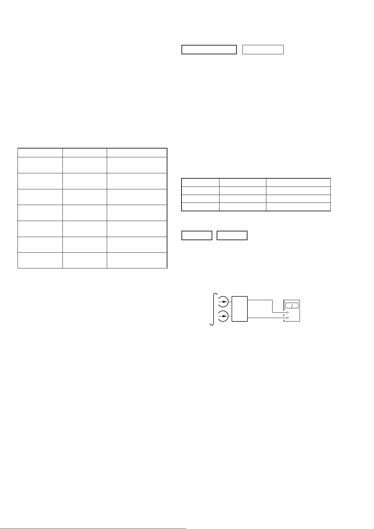
LEAKAGE
The A C leakag e from any exposed metal part to earth g round and
from all exposed metal parts to any exposed metal part having a
return to chassis, must not exceed 0.5 mA (500 microampers).
Leakage current can be measured by any one of three methods.
1. A commercial leakage tester, such as the Simpson 229 or RCA
WT -540A. Follo w the manufacturers’ instructions to use these
instruments.
2. A battery-operated AC milliammeter. The Data Precision 245
digital multimeter is suitable for this job.
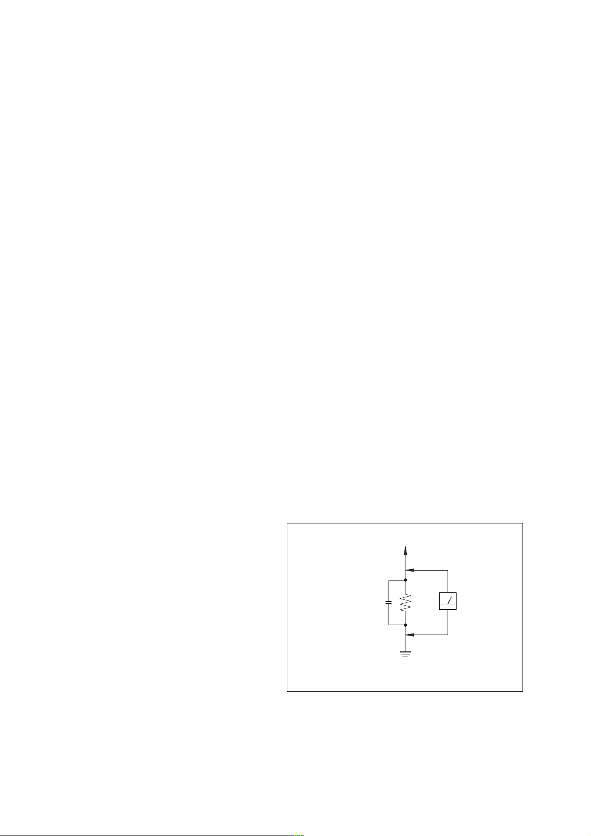
3. Measuring the voltage drop across a resistor by means of a
VOM or battery-operated A C voltmeter . The “limit” indication
is 0.75 V, so analog meters must have an accurate low-voltage
scale. The Simpson 250 and Sanwa SH-63Trd are e xamples of
a passive VOM that is suitable. Nearly all battery operated
digital multimeters that have a 2V AC range are suitable. (See
Fig. A)
To Exposed Metal
Parts on Set
AC
0.15µF
1.5kΩ
voltmeter
(0.75V)
SAFETY-RELATED COMPONENT WARNING!!
COMPONENTS IDENTIFIED BY MARK 0 OR DOTTED LINE WITH
MARK 0 ON THE SCHEMATIC DIAGRAMS AND IN THE PARTS
LIST ARE CRITICAL TO SAFE OPERATION. REPLACE THESE
COMPONENTS WITH SONY PARTS WHOSE PART NUMBERS
APPEAR AS SHOWN IN THIS MANUAL OR IN SUPPLEMENTS
PUBLISHED BY SONY.
2
Earth Ground
Fig. A. Using an AC voltmeter to check AC leakage .
ATTENTION AU COMPOSANT AYANT RAPPORT
À LA SÉCURITÉ!
LES COMPOSANTS IDENTIFÉS P AR UNE MARQUE 0 SUR LES
DIAGRAMMES SCHÉMA TIQUES ET LA LISTE DES PIÈCES SONT
CRITIQUES POUR LA SÉCURITÉ DE FONCTIONNEMENT. NE
REMPLACER CES COMPOSANTS QUE PAR DES PIÈSES SONY
DONT LES NUMÉROS SONT DONNÉS DANS CE MANUEL OU
DANS LES SUPPÉMENTS PUBLIÉS PAR SONY.
NOTES ON HANDLING THE OPTICAL PICK-UP
BLOCK OR BASE UNIT
TABLE OF CONTENTS
1. SERVICE NOTE······························································· 4
The laser diode in the optical pick-up block may suffer electrostatic
break-down because of the potential difference generated by the
charged electrostatic load, etc. on clothing and the human body.
During repair, pay attention to electrostatic break-down and also
use the procedure in the printed matter which is included in the
repair parts.
The flexible board is easily damaged and should be handled with
care.
NOTES ON LASER DIODE EMISSION CHECK
The laser beam on this model is concentrated so as to be focused on
the disc reflective surface by the objective lens in the optical pickup block. Therefore, when checking the laser diode emission,
observe from more than 30 cm away from the objective lens.
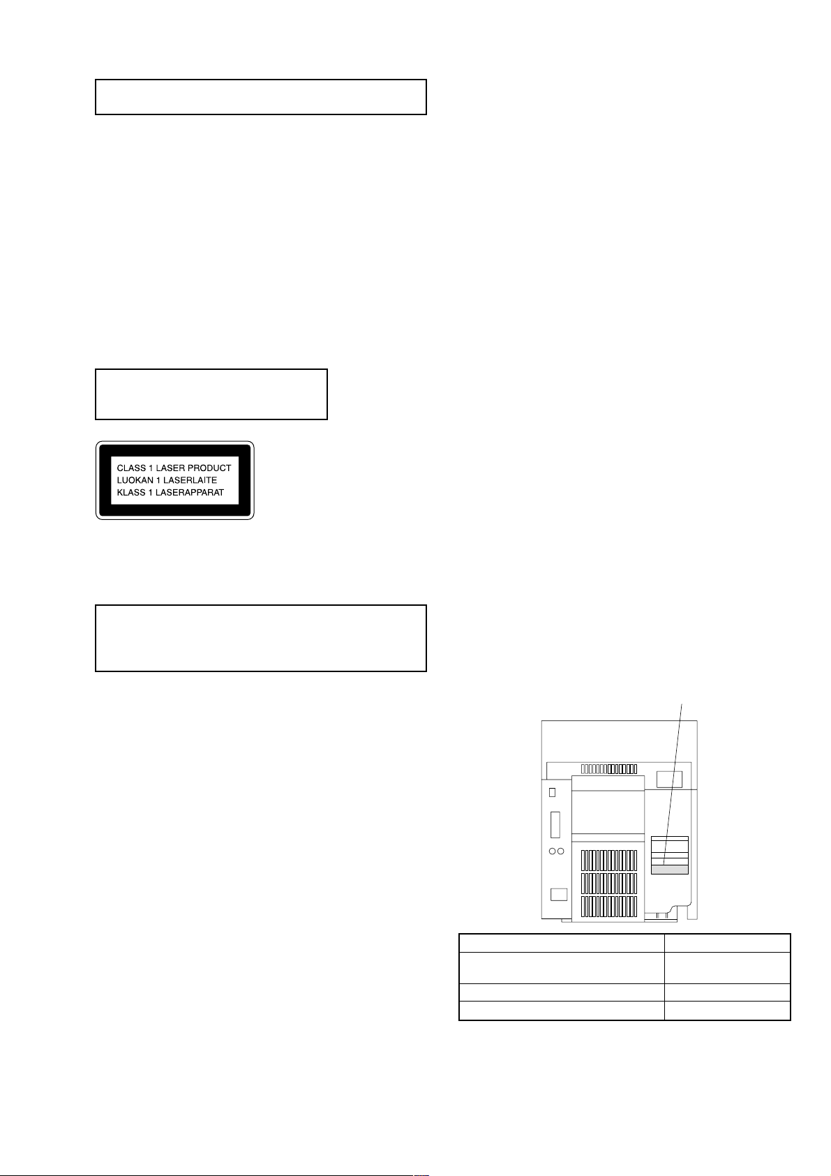
Laser component in this product is capable
of emitting radiation exceeding the limit for
Class 1.
This appliance is classified as a CLASS 1 LASER product. The
CLASS 1 LASER PRODUCT MARKING is located on the rear
exterior.
CAUTION
Use of controls or adjustments or performance of procedures
other than those specified herein may result in hazardous radiation
exposure.
Notes on chip component replacement
• Never reuse a disconnected chip component.
• Notice that the minus side of a tantalum capacitor may be
damaged by heat.
2. GENERAL ·········································································· 5
3. DISASSEMBY ·································································· 7
4. TEST MODE ···································································· 12
5. MECHANICAL ADJUSTMENTS ····························· 16
6. ELECTRICAL ADJUSTMENTS ······························· 16
7. DIAGRAMS
7-1. Circuit Board Location ················································· 21
7-2. Block Diagrams ···························································· 22
7-3. Printed Wiring Board BD Section ···························· 24
7-4. Schematic Diagram BD Section ······························· 25
7-5. Printed Wiring Board Main Section ························· 26
7-6. Schematic Diagram Main Section (1/3) ··················· 27
7-7. Schematic Diagram Main Section (2/3) ··················· 28
7-8. Schematic Diagram Main Section (3/3) ··················· 29
7-9. Printed Wiring Board AMP Section ························· 30
7-10. Schematic Diagram AMP Section ·························· 31
7-11. Printed Wiring Board Panel Section ······················· 32
7-12. Schematic Diagram Panel Section ·························· 33
7-13. Printed Wiring Board Leaf SW Section·················· 34
7-14. Schematic Diagram Leaf SW Section ···················· 35
7-15. Printed Wiring Board Driver Section······················ 36
7-16. Schematic Diagram Driver Section ························ 37
7-17. Printed Wiring Board Trans Section ······················· 38
7-18. Schematic Diagram Trans Section··························39
7-19. IC Pin Function Description ······································· 40
7-20. IC Block Diagrams ····················································· 42
8. EXPLODED VIEWS
8-1. Main Section ································································· 45
8-2. Panel Section ································································ 46
8-3. Main Board Section ······················································ 47
8-4. Tape Mechanism Section·············································· 48
8-5. CD Mechanism Section ················································ 49
9. ELECTRICAL PARTS LIST ······································· 50
MODEL IDENTIFICATION
— BACK PANEL —
PARTS No.
Flexible Circuit Board Repairing
• Keep the temperature of soldering iron around 270˚C
during repairing.
• Do not touch the soldering iron on the same conductor of the
circuit board (within 3 times).
• Be careful not to apply force on the conductor when soldering
or unsoldering.
MODEL
AED, AEP, CIS, UK, G, AUS,
KR, MX, TH models
AR, E, EA, SP, TW, MY models
US, CND models
• Abbreviation
CND : Canadian model
AUS : Australian model
G : German model
AED : North European model
EA : Saudi Arabia model
MY : Malaysia model
PARTS No.
4-225-040-0s
4-225-040-1s
4-225-040-2s
SP : Singapore model
TH : Thai model
TW : Taiwan model
KR : Korea model
MX : Mexican model
AR : Argentina model
3
SECTION 1
SERVICE NOTE
2
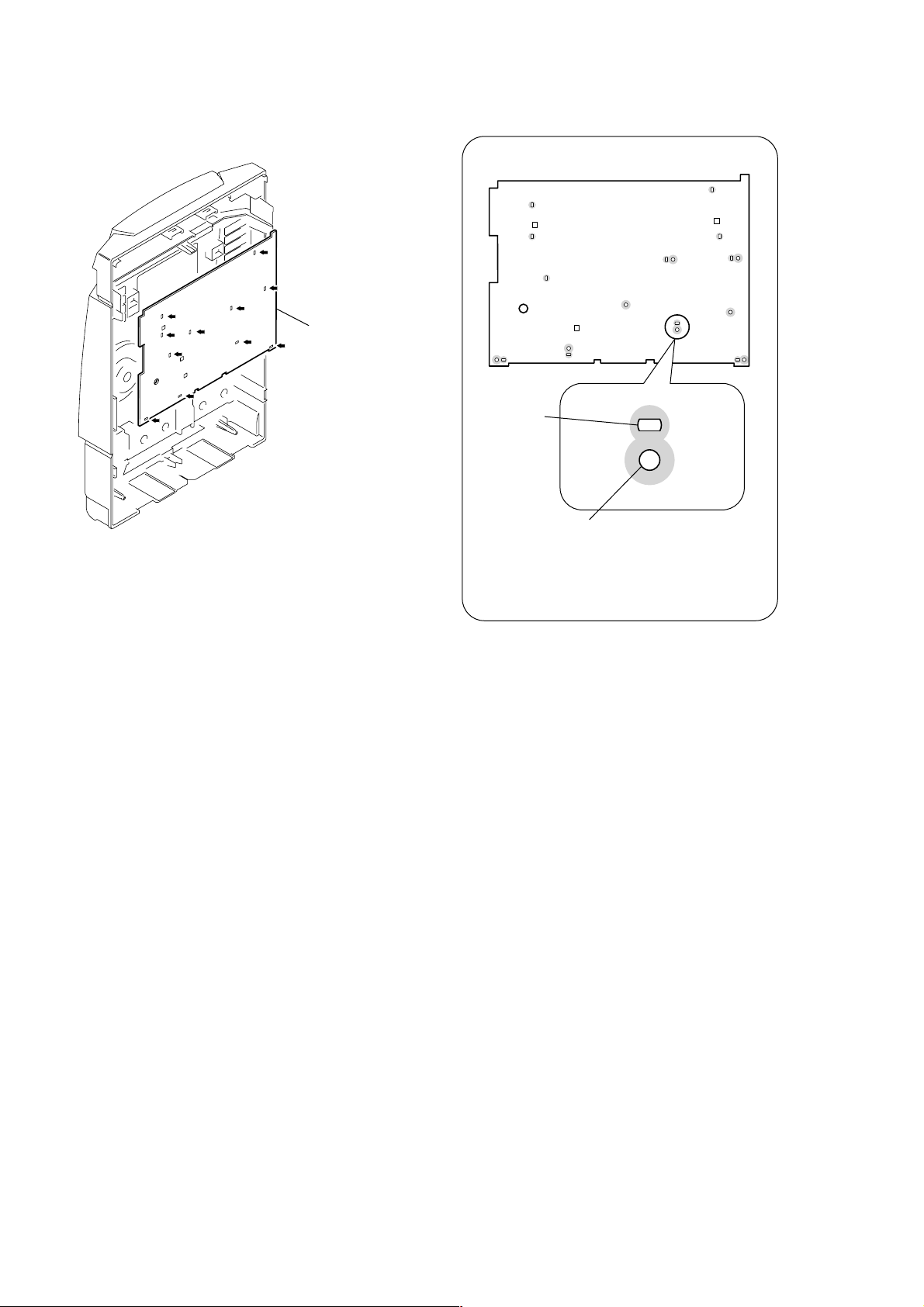
Panel board
Note for installing the panel board
Hot melt
1
Cut the eleven melted-connection points with a cutting plier.
Screw hole
Attach the panel board with
six screws (
after the board is removed once.
Do not tighten the screws excessively.
+BVTP 2.6 × 8
)
4
SECTION 2
12345
6
7
8
qa
qs
qd
qfqgqh
qk
w;
ea
es
wf
wg
wh
wj
wk
wl
9
q;
ql
qj
wa
ws
wd
e;
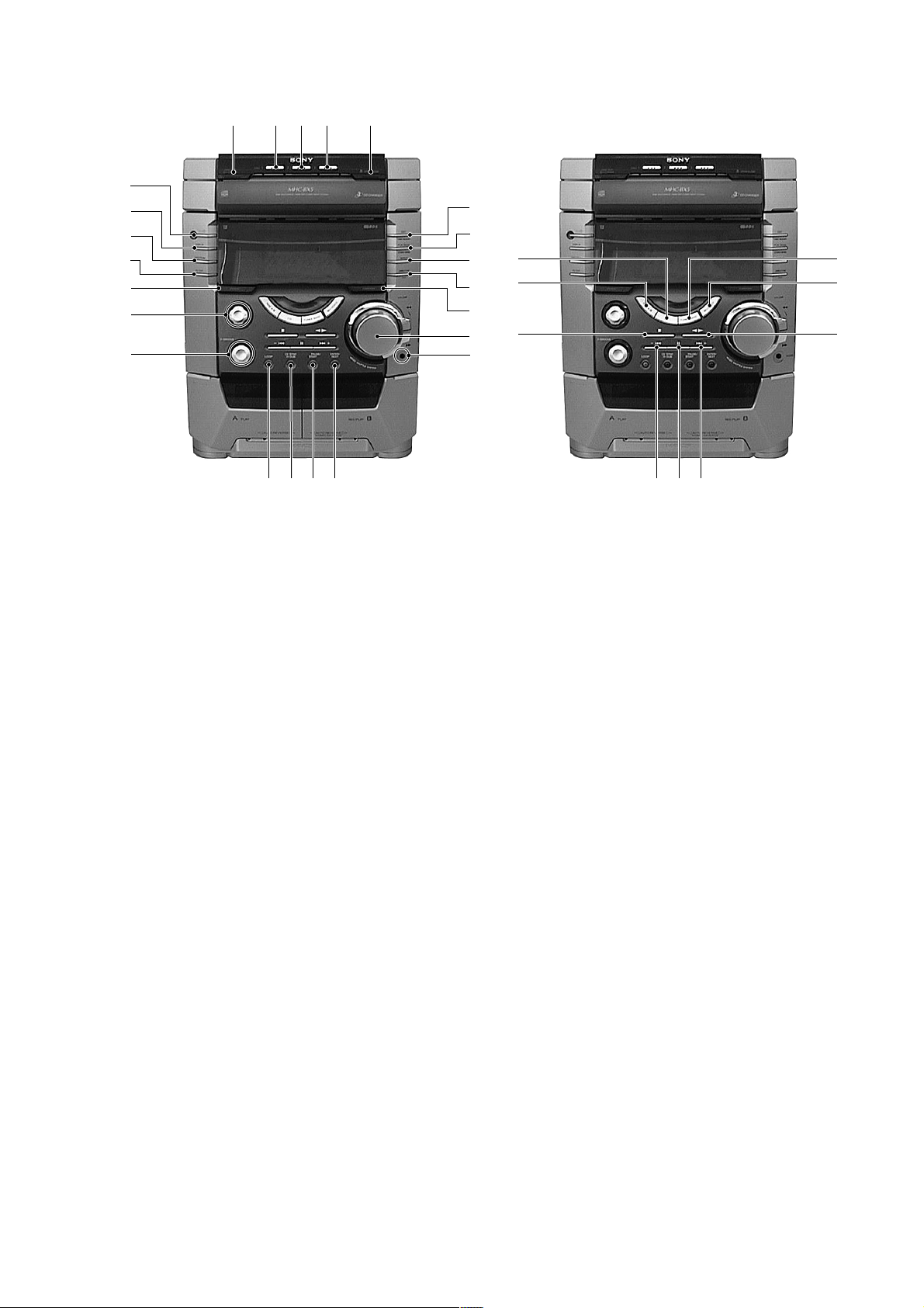
GENERAL
1 DISC SKIP EX-CHANGE button
2 DISC 1 button and indicator
3 DISC 2 button and indicator
4 DISC 3 button and indicator
5 Z OPEN/CLOSE button
6 EDIT, TUNER MOMERY button
7 PLAY MODE, STEREO/MONO button
8 REPEAT button
9 DIRECTION, PTY knob
q; SURROUND button
qa VOLUME knob
qs PHONE jack
qd ENTER/NEXT button
qf REC/PAUSE START button and indicator
qg CD SYNC HI-DUBB button
qh LOOP button
Photo: HCD-BX5
qj V-GROOVE button and indicator
qk CURSOL button and indicator
ql GROOVE button
w; EQ EDIT button
wa SPECTRUM button
ws DISPLAY button
wd ?/1 button and indicator
wf TUNER BAND button
wg MD (VIDEO) button
wh Y button
wj > + button
wk X button
wl – . button
e; x button
ea T APE A/B button
es CD button
5
6
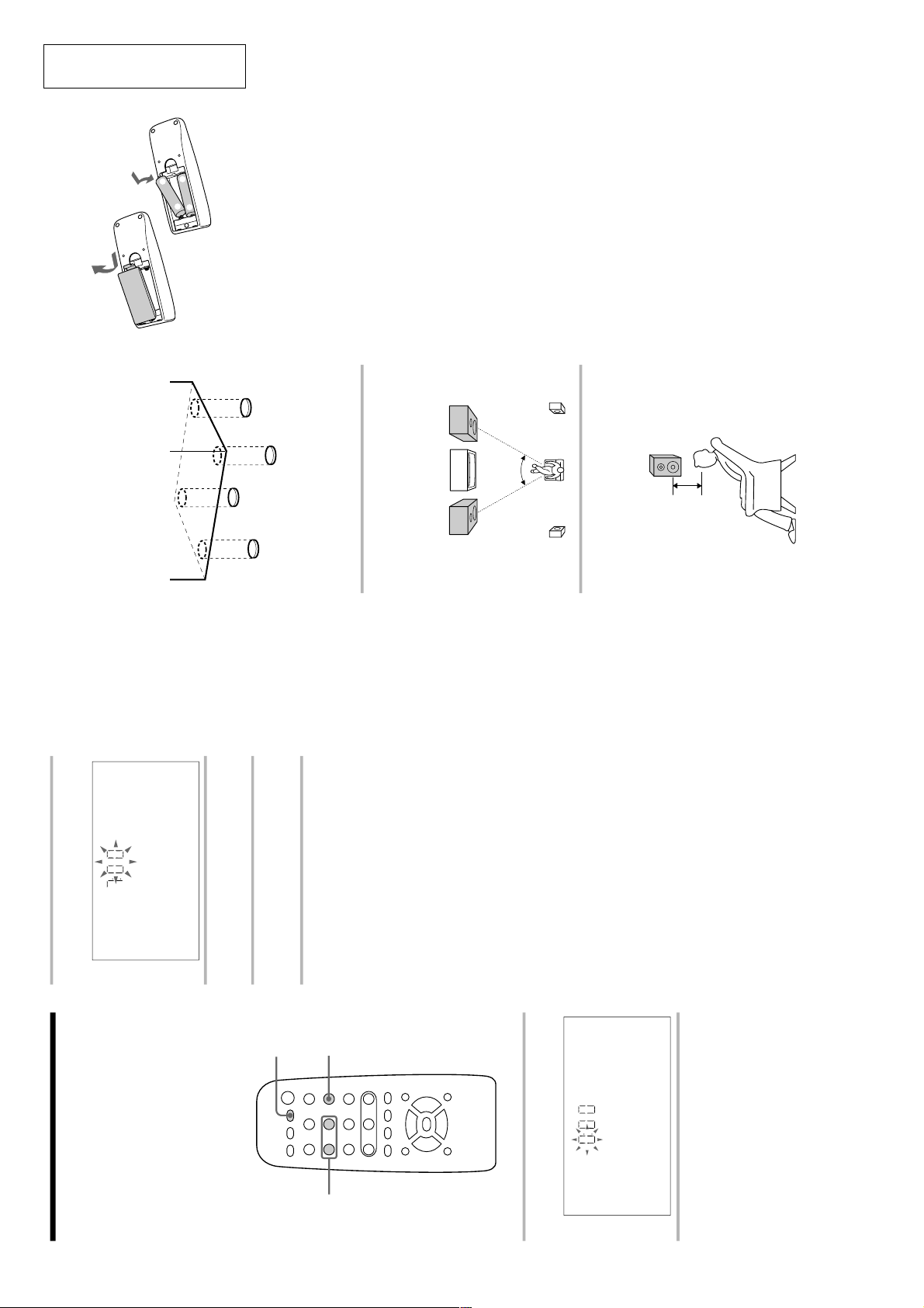
Step 1: Hooking up the system
(continued)
To attach the front speaker pads
Attach the supplied front speaker pads to the
bottom of the speakers to stabilize the
speakers and prevent them from slipping.
Positioning the speakers
(MHC-BX7/DX7 only)
Before you connect them, determine the best
location for your speakers.
1
Place the front speakers at an angle
of 45 degrees from your listening
position.
2
Place the surround speakers facing
each other at about 60 to 90 cm
above your listening position.
E
e
e
E
Front
speaker
(L)
Front
speaker
(R)
Surround
speaker
(L)
Surround
speaker
(R)
45º
Surround
speaker
60 to 90 cm
Inserting two size AA (R6)
batteries into the remote
Tip
With normal use, the batteries should last for about
six months. When the remote no longer operates
the system, replace both batteries with new ones.
Note
If you do not use the remote for a long period of
time, remove the batteries to avoid possible damage
from battery leakage.
When carrying this system
Do the following to protect the CD
mechanism.
1 Make sure that all discs are removed from
the unit.
2 Hold down CD and then press ?/1 so that
“LOCK” appears in the display.
3 Unplug the AC power cord.
7
1
Press CLOCK/TIMER SET.
The hour indication flashes.
2
Press . or > repeatedly to set
the hour.
3
Press ENTER.
The minute indication flashes.
4
Press . or > repeatedly to set
the minute.
5
Press ENTER.
The clock starts working.
Tip
If you’ve made a mistake, start over from step 1.
To change the time
The previous explanation shows you how to set the
time while the power is off. To change the time
while the power is on, do the following:
1 Press CLOCK/TIMER SET.
2 Press . or > repeatedly to select
SET CLOCK.
3 Press ENTER.
4 Perform steps 2 through 5 above.
Note
The clock settings are canceled when you disconnect
the power cord or if a power failure occurs.
Step 2: Setting the
time
You must set the time before using the timer
functions.
The clock is on a 24-hour system for the
European model and a 12-hour system for
other models.
The 24-hour system model is used for
illustration purposes.
0)
=+
œP p
(P p
1
3,5
2,4
This section is extracted from
instruction manual.
6
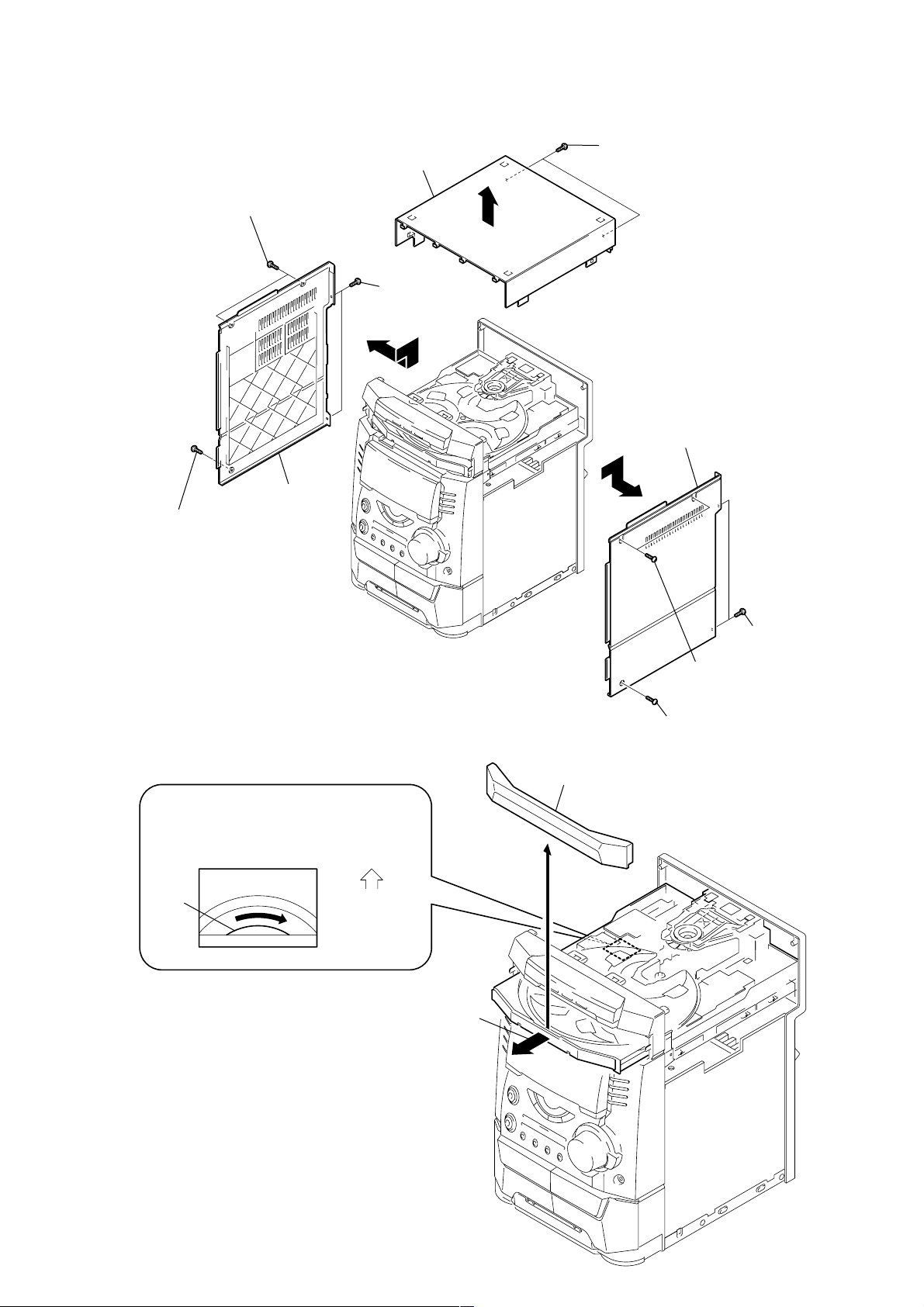
SECTION 3
DISASSEMBY
Note : Follow the disassembly procedure in the numerical order given.
3-1. UPPER CASE (TOP)
5
Two screws (Case)
Side panel L
Upper case (Top)
7
Two screws
(+BVTP 3
8
×
q;
10)
9
Two screws (+BVTP 3
Side panel R
4
×
10)
6
Screw (Case)
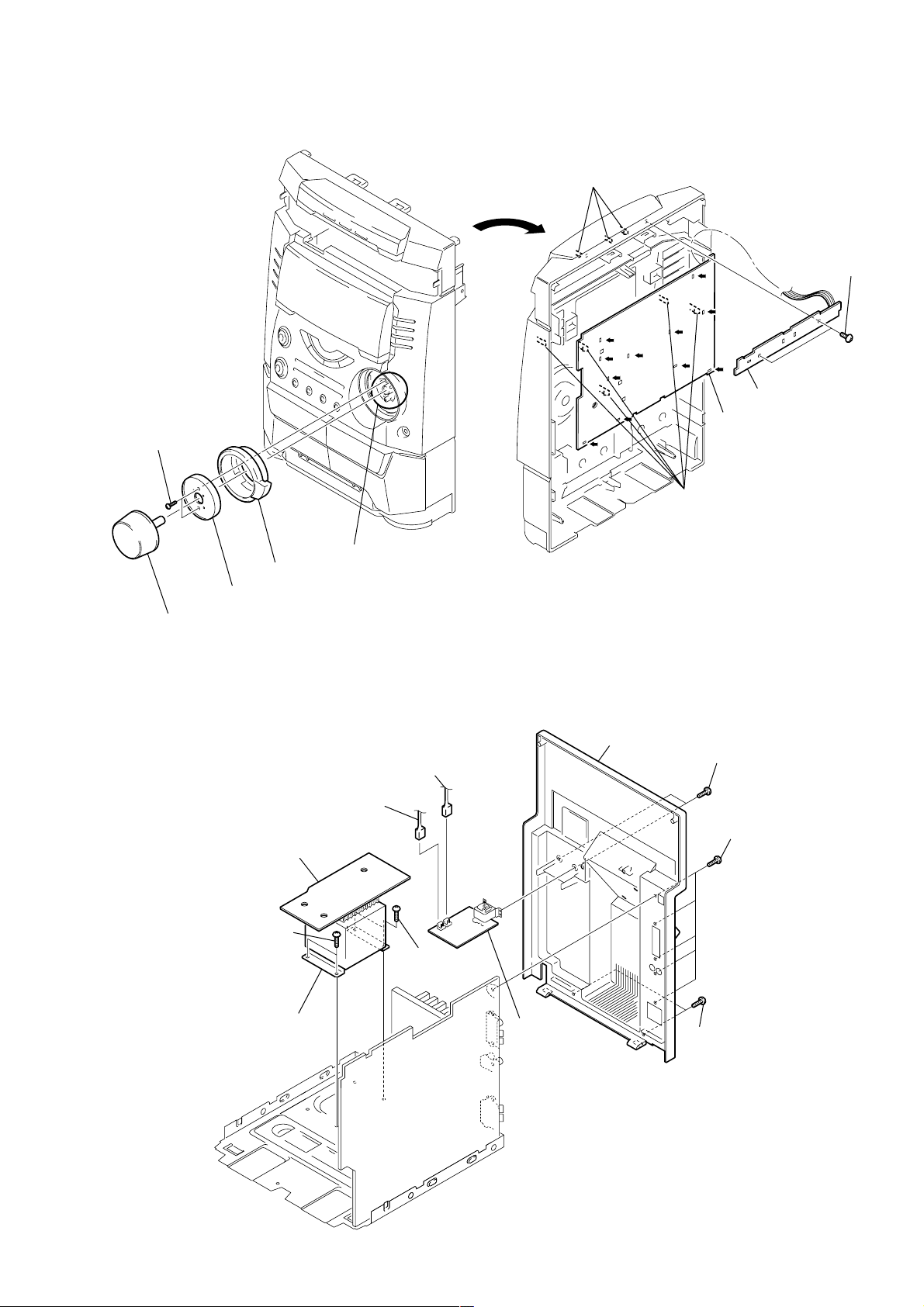
3-2. LOADING PANEL ASSY
CD mechanism deck (CDM58)
1
Turn the pulley to the direction of arrow.
pulley
Front panel side
Loading panel assy
3
1
Two screws (Case)
2
Screw (Case)
3
Two screws
2
Pull-out the disc tray.
7
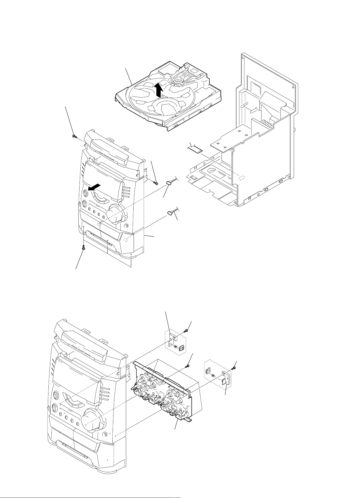
3-3. FRONT PANEL SECTION
CD mechanism deck (CDM58)
4
Screw (+BVTP 3
7
×
10)
8
1
Flat type wire (CN304)
5
Screw (+BVTP 3
2
Connector (CN1)
×
10)
6
Three screws (+BVTT 3
3-4. TAPE MECHANISM DECK
×
3
Connector (CN2)
Front panel section
6)
4
Bracket (Heart cam L)
3
Screw (+BVTP 2.6
5
Five screws (+BVTP 2.6
×
8)
×
8)
1
Screw (+BVTP 2.6
×
8)
2
Bracket (Heart cam R)
6
Tape mechanism deck
8
)
3-5. PANEL BOARD
2
Two screws
(+BVTP 2.6
×
8)
1
Knob (Volume)
4
5
FR knob
Bracket (FR)
3
Two bosses & four pins
8
Three claws
6
7
Two screws
(+BVTP 3
9
CD Switch board
qs
Panel board
qa
Five claws
q;
Cut the eleven melted-connection points with a cutting plier.
Note: When attching the panel board,
refer to "Service Note" on page 4.
×
10)
3-6. SUB-TRANS BOARD AND TRANS BOARD
2
Connector (CN974)
1
Connector (CN975)
qa
Trans board
9
Two screws (+BVTT 4
q;
×
6)
Trans
8
Two screws
(+BVTT 4
×
7
Panel, back
3
Two screws
(+BVTP 3
6
(+BVTP 3
6)
4
Sub-trans
board
5
Two screws
(+BVTP 3
×
8)
Five screws
×
×
10)
10
9
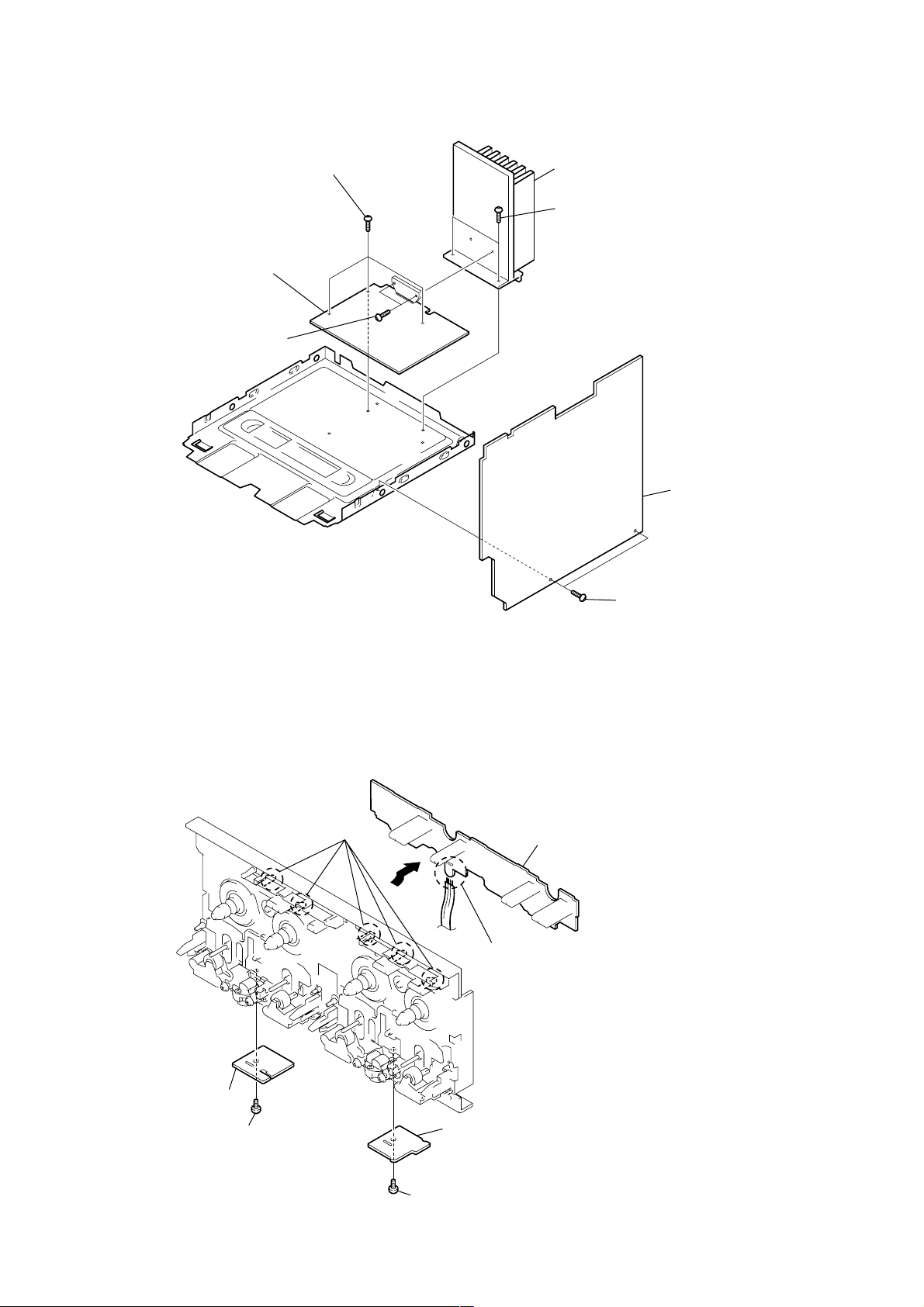
)
3-7. MAIN BOARD AND AMP BOARD
4
Three screws (+BVTP 3
5
Power
AMP board
3
Two screws (+BVTP 3
×
10)
×
10)
7
Heat sink
6
Two screws (+BVTP 3
×
10)
2
Main board
3-8. LEAF SW BOARD, HEAD (A) BOARD AND HEAD (B) BOARD
1
Five claws
6
1
Two screws (+BVTP 3
2 Leaf
SW board
Remove the four solderings.
×
8
10
4
Head (A) board
3
Screw (+PS 2.6
×
5
5)
6
Head (B) board
Screw (+PS 2.6
×
5)
)
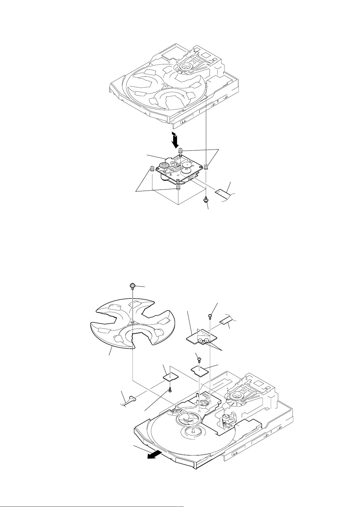
3-9. BASE UNIT
5
Two insulators
Base unit
3
4
Two insulators
1
Flat type wire (CN101
2
Four screws (+PTPWH 2.6)
3-10. DRIVER BOARD, MOTOR BOARD AND ADDRESS SENSOR BOARD
8
9
Tray
3
Connector (CN701)
1
Screw (+BVTP 2.6
Screw (+PTPWH 2.6
q;
Screw (+BVTP 2.6
2
Driver board
×
8)
7
×
8)
Motor board
×
5
Three screws (+BVTP 2.6
4
Flat type wire (CN721)
8)
6
Remove the two solderings of motor.
qa
Address sensor board
×
8)
3
Pull-out the disc tray.
11

SECTION 4
TEST MODE
[MC Cold Reset]
• The cold reset clears all data including preset data stored in the
RAM to initial conditions. Execute this mode when returning
the set to the customer.
Procedure:
1. Press three buttons x , ENTER , and ?/1 simulta-neously.
2. The fluorescent indicator tube displays “COLD RESET” and
the set is reset.
[CD Ship Mode]
• This mode moves the pickup to the position durable to vibration. Use this mode when returning the set to the customer after
repair.
Procedure:
1. Press 1/u button to turn the set ON.
2. Press CD button and 1/u button simultaneously.
3. After the "STANDBY" display blinks six times, a message
“LOCK” is displayed on the fluorescent indicator tube, and the
CD ship mode is set.
[MC Hot Reset]
• This mode resets the set with the preset data kept stored in the
memory. The hot reset mode functions same as if the power
cord is plugged in and out.
Procedure:
1. Press three buttons x , ENTER , and DISC 1 simultaneously.
2. The fluorescent indicator tube becomes blank instantaneously,
and the set is reset.
[CD Service Mode]
• This mode can run the CD sled motor freely. Use this mode, for
instance, when cleaning the pickup.
Procedure:
1. Press ?/1 button to turn the set ON.
2. Select the function “CD”.
3. Press three buttons x , ENTER , and OPEN/CLOSE simul-
taneously.
4. The CD service mode is selected.
5. With the CD in stop status, turn the shuttle knob clockwise to
move the pickup to outside track, or turn the shuttle knob
counter-clockwise to inside track.
6. To exit from this mode, perform as follows:
1) Move the pickup to the most inside track.
2) Press three buttons in the same manner as step 2.
Note: • Always move the pickup to most inside track when exiting from
this mode. Otherwise, a disc will not be unloaded.
• Do not run the sled motor excessively, otherwise the gear can be
chipped.
[Change-over of MW Tuner Step between 9 kHz and
10 kHz]
• A step of MW channels can be changed over between 9 kHz
and 10 kHz.
Procedure:
1. Press ?/1 button to turn the set ON.
2. Select the function “TUNER”, and press TUNER/BAND
button to select the BAND “MW”.
3. Press ?/1 button to turn the set OFF.
4. Press ENTER and ?/1 buttons simultaneously , and the display
of fluorescent indicator tube changes to “MW 9 k STEP” or
“MW 10 k STEP”, and thus the channel step is changed over.
[GC Test Mode]
• This mode is used to check the software version, FL tube, LED,
keyboard and VACS.
Procedure:
1. Press three buttons x , ENTER , and DISC 2 simultaneously.
2. LEDs and fluorescent indicator tube are all turned on.
3. When you want to enter the software version display mode,
press DISC 1 . The model number and destination are displayed.
4. Each time DISC 1 is pressed, the display changes starting
from MC version, GC version, VC version, CD version, CM
version, ST version, TC version, TA version, TM version and
BR version in this order, and returns to the model number and
destination display .
5. When DISC 3 is pressed while the version numbers are being
displayed except model number and destination, year, month
and day of the software creation appear. When DISC 3 is
pressed again, the display returns to the software version display .
When DISC 1 is pressed while year, month and day of the
software creation are being displayed, the year, month and day
of creation of the software versions are displayed in the same
order of version display.
6. Press DISC 2 button, and the key check mode is activated.
7. In the key check mode, the fluorescent indicator tube displays
“KEY0 VOL0”. Each time a button is pressed, “KEY” value
increases. However, once a button is pressed, it is no longer
taken into account.
“VOL” value increases like 1, 2, 3 ... if rotating VOLUME
knob in “+” direction, or it decreases like 0, 9, 8 ... if rotating in
“–” direction.
8. Also when DISC 3 is pressed after lighting of all LEDs and FL
tubes, value of VACS appears.
9. T o e xit from this mode, press three b uttons in the same manner
as step 1, or disconnect the power cord.
[VACS ON/OFF Mode]
• This mode is used to switch ON and OFF the VACS (Variable
Attenuation Control System).
Procedure:
Press the ENTER and SPECTRUM buttons simultaneously. The
message “VACS OFF” or “VACS ON” appears.
12

[MC Test Mode]
• This mode is used to check operations of the respective sections
of Amplifier, Tuner, CD and Tape.
Procedure:
1. Press the ?/1 button to turn on the set.
2. Press the three buttons of x , ENTER and DISC 3
simultaneously.
3. A message “TEST MODE” appears on the FL display tube.
4 When f (CURSOR UP) button is pressed, GEQ increases to
its maximum and a message “GEQ ALL MA” appears.
5. When F (CURSOR DOWN) button is pressed, GEQ decreases
to its minimum and a message “GEQ ALL M1” appears.
6. When g (CURSOR LEFT) or G (CURSOR RIGHT) button
is pressed, GEQ is set to flat and a message “GEQ FLAT”
appears.
7. When the VOLUME control knob is turned clockwise even
slightly, the sound volume increases to its maximum and a
message “V OLUME MAX” appears for two seconds, then the
display returns to the original display.
8. When the V OLUME control knob is turned counter-clockwise
even slightly, the sound volume decreases to its minimum and
a message “VOLUME MIN” appears for two seconds, then
the display returns to the original display.
9. In the test mode, the default-preset channel is called even when
the TUNER is selected and an attempt is made to call the preset
channel that has been stored in memory, by oper ating the Shuttle
knob. (It means that the memory is cleared.)
10. When CD is selected and the EDIT button is pressed, the disc
that is being chucked at this moment becomes the default
setting. It means that the default disc only is accessed when
any other discs are selected even though the display indication
changes accordingly. At the same time, the DISK SKIP EXCHANGE and OPEN/CLOSE cannot be accepted. (It means
that the tray motor and the turntable motor are disabled of their
operation.)
11. When a tape is inserted in Deck B and recording is started, the
input source function selects VIDEO automatically.
12. When x button is pressed to stop recording, the Tape (Deck)
B is selected and tape is rewound using the Shuttle knob, tape
is rewound, tape is stops at around the record-starting position
and playback of the recorded portion of the tape is started. If
P A USE is inserted even once during recording, ta pe is rewound
to the position around the P AUSE position and is played back.
13. When the CD SYNC HI-DUB Button is press during playback
of Deck B, either normal speed or high speed can be selected
by this button.
14. Select the desired loop by pressing the PLAY MODE b utton.
Insert a test tape AMS-110A or AMS-RO to Deck A.
15. Press the SPECTRUM button to enter the AMS test mode.
16. After a tape is rewound first, the FF AMS is checked, and the
mechanism is shut off after detecting the AMS signal twice.
17. Then the REW AMS is checked and the mechanism is shut off
after detecting the AMS signal twice.
18. When the check is complete, a message of either OK or NG
appears.
19. When you want to exit this mode, press the ?/1 button twice.
The cold reset is enforced at the same time.
13
[Aging Mode]
This mode can be used for operation check of CD section and tape deck section.
• If an error occurred:
The aging operation stops and display status.
• If no error occurs:
The aging operation continues repeatedly.
1. Operating method of Aging Mode
Turn on the main power and select “CD” of the function.
1) Set a disc in DISC1 tray. Select ALL DISC CONTINUE, and REPEAT OFF.
2) Load the tapes recording use into the decks A and B respectively.
3) Press three buttons x , ENTER , and
DISC SKIP/EX-CHANGE simultaneously.
4) Aging operations of CD and tape are started at the same time.
5) To exit the aging mode, perform [MC Cold Reset].
3. Aging Mode in CD section
1) Display state
• No error occurs
Display
AGING[*][*][*][*]
Note:
[*][*][*][*]
Error display
E ** s ## $$ %%
12 34 5
1 **
2 s
3 ##
4 $$
5 %%
: Number of aging operations
The error No. 00 indicates the newest error. As the error No. increases, it means the older error.
When you want to retrieve the error history, press the PLAY MODE button in the case of mechanism error.
Or press the REPEAT button in the case of NO DISC error.
M: Mechanism error
Don’t care
High order digits only
D: Stopped during closing due to problems other than mechanism.
E: Stopped during opening due to problems other than mechanism.
C: Stopped during chucking due to problems other than mechanism.
F: Stopped during EX-opening due to problems other than mechanism.
Emergency related errors (High order digits only)
1: Stopped during chuck-up
2: Stopped during chuck-down
3: Time out by EX-OPEN
5: Time out by EX-CLOSE
D: No disc error
01: FOCUS ERROR
02: GFS ERROR
03: SETUP ERROR
01: NO DISC judgment without chucking retry
02: NO DISC judgment after chucking retry
Status at the time of NO DISC judgment
(High order digits only)
1: STOP
2: SETUP
3: TOC READ
4: ACCESS
5: PLAY BACK
6: PAUSE
7: MANUAL SEARCH (PLAY)
8: MANUAL SEARCH (PAUSE)
• When the buttons x , ENTER and DISC 1 are pressed simultaneously, number of time of the mechanism error and the NO DISC error
can be checked.
Display: EMC**EDC** **: Number of times of error (Maximum three times)
EMC: Mechanism error
EDC: NO DISC error
• When aging operation is complete, be sure to perform the MC Cold Reset to reset the error history.
14
2) Operation during aging mode
In the aging mode, the program is executed in the following
sequence.
(1) The disc tray opens and closes.
(2) The mechanism accesses DISC 2 and makes an attempt to
read TOC. However, since there are no discs, a message
“CD2 NO DISC” appears.
(3) The mechanism accesses DISC 3 and a message “CD3 NO
DISC” appears.
(4) The disc tray turns to select a disc1.
(5) A disc is chucked.
(6) TOC of disc is read.
(7) The pickup accesses to the track 1, and playing 2 seconds.
(8) The pickup accesses to the last track, and playing 2 seconds.
(9) Every time when an aging operation of step 1 to step 8 is
complete, the display “AGING[*][*][*][*]” value increases
as the number of aging operations is counted up.
(10) Returns to step 1.
3. Aging Mode in Tape Deck section
1) Display state
• No error occurs
Display action now
• Error occurred
Display action last time
NO. Display action Action contents Final timing
1 TAPE A AG-1 Rewind the TAPE A, B The top of tape
2 TAPE A AG-2 FWD play the TAPE A 2 minutes playing
3 TAPE A AG-3 F.F. the TAPE A 20 second FF or the end
4 TAPE A AG-4 REV play the TAPE A 2 minutes playing
5 TAPE A AG-5 Rewind the TAPE A The top of tape
6 TAPE B AG-2 FWD play the TAPE B 2 minutes playing
7 TAPE B AG-3 F.F . the TAPE B 20 second FF or the end
8 TAPE B AG-4 REV play the TAPE B 2 minutes playing
9 TAPE B AG-5 Rewind the TAPE B The top of tape
of tape
of tape
2) Operation during aging mode
In the aging mode, the program is executed in the following
sequence.
(1) Rewind is executed up to the top of tape A and B.
(2) A tape on FWD side is played for 2 minutes.
(3) FF is executed up to either made for 20 second or the end of
tape.
(4) A tape is reversed, and the tape on REV side is played for 2
minutes.
(5) Rewind is executed up to the top of tape.
(6) Returns to step 2, and repeat steps from 2 to 5.
[Function Change Mode]
* elect either VIDEO or MD of the external FUNCTION input.
Procedure:
1. Turn on the power.
2. Press the two buttons ENTER and ?/1 at the same time.
The main power is turned on and the other function of the
previous function is selected and displayed. “MD” or
“VIDEO”.
15
SECTION 5
r
MECHANICAL ADJUSTMENTS
SECTION 6
ELECTRICAL ADJUSTMENTS
Precaution
1. Clean the following parts with a denatured alcohol-moistened
swab:
record/playback heads pinch rollers
erase head rubber belts
capstan idlers
2. Demagnetize the record/playback head with a head
demagnetizer.
3. Do not use a magnetized screwdriver for the adjustments.
4. After the adjustments, apply suitable locking compound to the
parts adjusted.
5. The adjustments should be performed with the rated power
supply voltage unless otherwise noted.
Torque Measurement
Mode Torque meter
FWD
FWD
back tension
REV
REV
back tension
FF/REW
FWD tension
REV tension
CQ-102C
CQ-102C
CQ-102RC
CQ-102RC
CQ-201B
CQ-403A
CQ-403R
Meter reading
31 to 71 g • cm
(0.43 – 0.98 oz • inch)
2 to 6 g • cm
(0.02 – 0.08 oz • inch)
31 to 71 g • cm
(0.43 – 0.98 oz • inch)
2 to 6 g • cm
(0.02 – 0.08 oz • inch)
71 to 143 g • cm
(0.98 – 1.99 oz • inch)
100 g or more
(3.53 oz or more)
100 g or more
(3.53 oz or more)
DECK SECTION
1. Demagnetize the record/playback head with a head
demagnetizer.
2. Do not use a magnetized screwdriver for the adjustments.
3. After the adjustments, apply suitable locking compound to the
parts adjust.
4. The adjustments should be performed with the rated power
supply voltage unless otherwise noted.
5. The adjustments should be performed in the order given in this
service manual. (As a general rule, playback circuit adjustment
should be completed before performing recording circuit
adjustment.)
6. The adjustments should be performed for both L-CH and RCH.
7. Switches and controls should be set as follows unless otherwise
specified.
• Test Tape
Tape Signal Used for
P-4-A100 10 kHz, –10 dB Azimuth Adjustment
WS-48B 3 kHz, 0 dB Tape Speed Adjustment
P-4-L300 315 Hz, 0 dB Level Adjustment
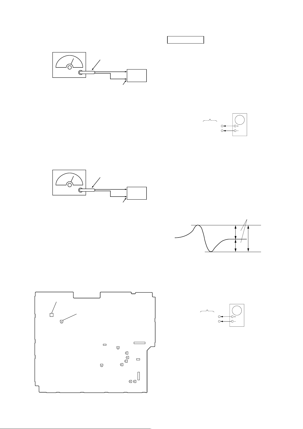
Record/Playback Head Azimuth Adjustment
0 dB=0.775 V
DECK A DECK B
Note: Perform this adjustments for both decks
Procedure:
1. Mode: Playback
test tape
P-4-A100
(10 kHz, –10 dB)
main board
CN301
Pin 3 (L-CH)
Pin 1 (R-CH)
set
main board
CN301
Pin 2 (GND)
level mete
+
–
16
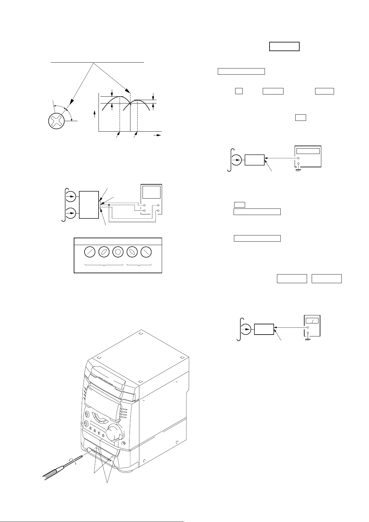
2. Turn the adjustment scre w and check output peaks. If the peaks
e
r
+
–
set
test tape
P-4-L300
(315 Hz, 0 dB)
main board
CN301 (Pin 3 : L-CH)
(Pin 1 : R-CH)
level meter
do not match for L-CH and R-CH, turn the adjustment screw
so that outputs match within 1dB of peak.
Output
level
within
1dB
L-CH
peak
R-CH
peak
within
1dB
Screw
position
L-CH
peak
Screw
position
R-CH
peak
Tape Speed Adjustment
Note: Start the Tape Speed adjustment as below after setting to the test
mode.
In the test mode, the tape speed is high during pressing the
DECK B
SD SYNC HI-DUB button.
Procedure:
1. Turn the power switch on.
2. Press the x button, ENTER button and DISC 3 button
simultaneously.
(The “TEST MODE” on the fluorescent indicator tube display
while in the test mode.)
To exit from the test mode, press the ?/1 button.
Mode: Playback
test tape
WS-48B
(3 kHz, 0 dB)
frequency counte
3. Mode: Playback
test tape
P-4-A100
(10 kHz, –10 dB)
L-CH
MAIN
board
CN301
set
R-CH
waveform of oscilloscope
in phase 45° 90° 135° 180°
pin 3
pin 2
L
R
pin 1
good
oscilloscop
V
wrong
H
4. After the adjustments, apply suitable locking compound to the
pats adjusted.
Adjustment Location: Playback Head (Deck A).
Record/Playback/Erase Head (Deck B).
set
main board
CN301 (Pin 3 : L-CH)
(Pin 1 : R-CH)
+
–
1. Insert the WS-48B into the deck B.
2. Press the gG button on the deck B.
3. Press the SD SYNC HI-DUB button in playback mode.
Then at HIGH speed mode.
4. Adjust RV1001 on the LEAF SW board do that frequency
counter reads 6,000 ± 30 Hz.
5. Press the SD SYNC HI-DUB button.
Then back to NORMAL speed mode.
6. Adjust RV1002 on the LEAF SW board so that frequency
counter reads 3,000 ± 15 Hz.
Adjustment Location: LEAF SW board
Playback level Adjustment
DECK A DECK B
Procedure:
Mode: Playback
forward
reverse
Deck A is RV302 (L-CH) and RV352 (R-CH), Deck B is RV303
(L-CH) and RV353 (R-CH) so that adjustment within adjustment
level as follows.
Adjustment Level:
CN301 PB level: 301.5 to 338.3 mV (–8.2 to –7.2 dB) level
difference between the channels: within ±0.5 dB
Adjustment Location: MAIN board
Sample Volue of Wow and Flutter: 0.3% or less W. RMS
(WS-48B)
17
REC Bias Adjustment DECK B
e
r
r
Procedure:
INTRODUCTION
When set to the test mode performed in Tape Speed Adjustment,
when the tape is rewound after recording, the “REC memory mode”
which rewinds only the recorded portion and playback is set.
This “REC memory mode” is convenient for performing this
adjustment. During recording, the input signal FUNCTION will
automatically switch to VIDEO.
(If do not operation of stopped from recording complete, and rotette
of shuttle knob then rewind to recording start position.)
4. Mode: Record
MD/VIDEO (AUDIO) IN
AF OSC
315 Hz, 50 mV (–23.8 dB)
attenuator
5. Mode: Playback
600 Ω
blank tape
CS-123
set
1. Press MD/VIDEO button to select VIDEO. (This step is not
necessary if the above test mode has already been set.)
2. Insert a tape into deck B.
3. After press REC PAUSE/ST ART button, press REC P AUSE/
START button, then recording start.
4. Mode: Record
MD/VIDEO (AUDIO) IN
1) 315 Hz
2) 10 kHz
AF OSC
attenuator
50 mV (–23.8 dB)
600 Ω
blank tap
CN-123
set
5. Mode: Playback
recorded
portion
set
CN301 (Pin 3 : L-CH)
(Pin 1 : R-CH)
level mete
+
–
recorded
portion
set
level mete
+
–
CN301 (Pin 3 : L-CH)
(Pin 1 : R-CH)
6. Confirm playback the signal recorded in step 3 become
adjustable level as follows.
If these levels do not adjustable level, adjustment the RV301
(L-CH) and R V351 (R-CH) on the MAIN board to repeat steps
4 and 5.
Adjustable level:
CN301 PB level: 47.2 to 53.0 mV (–24.3 to –23.3 dB)
Adjustment Location: MAIN board
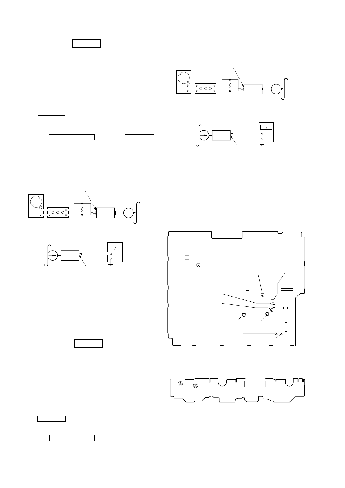
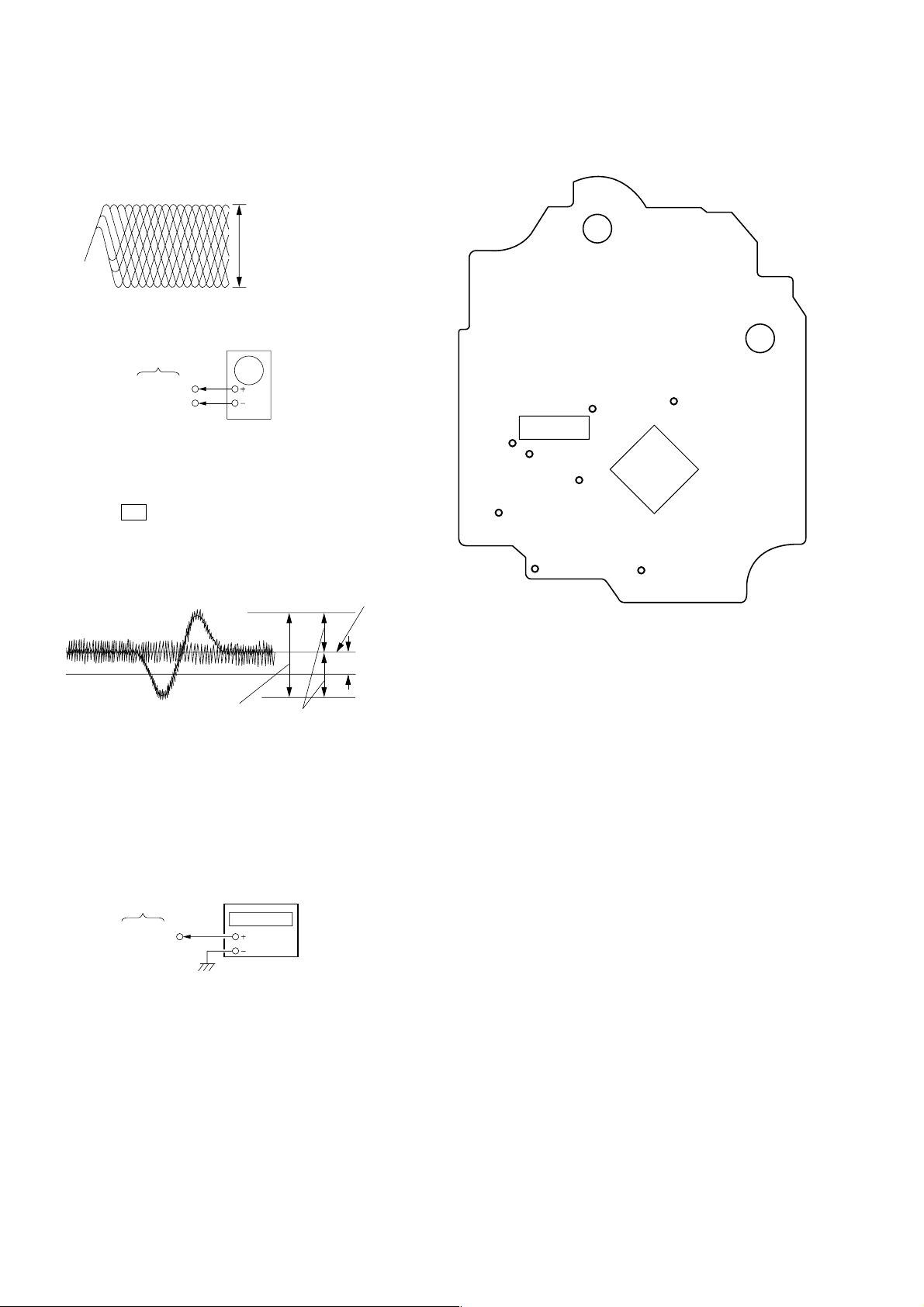
[MAIN BOARD] (Component Side)
T601
RV611
REC LEVEL (L)
(B)
PB LEVEL (L)
(A)
6. Confirm playback the signal recorded in step 3 become
adjustable level as follows.
If these levels do not adjustable level, adjustment the RV304
(L-CH) and RV354 (R-CH) on the A UDIO board to repeat steps
4 and 5.
Adjustable level: Playback output of 315 Hz to playback output
of 10 kHz: ±1.0 dB
Adjustment Location: MAIN board
REC Level Adjustment
DECK B
Procedure:
INTRODUCTION
When set to the test mode performed in Tape Speed Adjustment,
when the tape is rewound after recording, the “REC memory mode”
which rewinds only the recorded portion and playback is set.
This “REC memory mode” is convenient for performing this
adjustment. During recording, the input signal FUNCTION will
automatically switch to VIDEO.
(If do not operation of stopped from recording complete, and rotate
of shuttle knob then rewind to recording start position.)
1. Press MD/VIDEO button to select VIDEO. (This step is not
necessary if the above test mode has already been set.)
2. Insert a tape into deck B.
3. After press REC PAUSE/ST ART button, press REC P AUSE/
START button, then recording start.
PB LEVEL (R)
(A)
PB LEVEL (R)
(B)
REC LEVEL (R)
(B)
REC LEVEL (L)
(A)
CN301
RV351
PB LEVEL (L)
REC LEVEL (R)
[LEAF SW BOARD] (Component Side)
TAPE SPEED
(NORMAL) (HIGH)
RV1002
RV1001
13
RV303
(B)
(A)
CN1001
RV302
RV352
RV353
CN304
RV301
CN302
CN303
RV304
RV354
18
FM Tuned Level Adjustment
FM RF SSG
75 Ω coaxial
Carrier frequency : 98 MHz
Modulation : AUDIO 1 kHz, 75 kHz
deviation (100%)
Output level : 28 dB (at 75 W open)
set
FM ANTENNA terminal
(TM601)
CD SECTION
Note :
1. CD Block is basically designed to operate without adjustment.
Therefore, check each item in order given.
2. Use YEDS-18 disc (3-702-101-01) unless otherwise indicated.
3. Use an oscilloscope with more than 10MΩ impedance.
4. Clean the object lens by an applicator with neutral detergent
when the signal level is low than specified value with the
following checks.
S-Curve Check
Procedure:
1. Supply a 28 dB 98 MHz signal from the ANTENN A terminal.
2. Tune the set to 98 MHz.
3. Adjust RV611 to the point (moment) when the TUNED
indicator will change from going off to going on.
Adjustment Location: MAIN board
Null Adjustment
FM RF SSG
75 Ω coaxial
set
Carrier frequency : 98 MHz
Modulation : AUDIO 1 kHz, 75 kHz
deviation (100%)
Output level : 60 dB (at 75 W open)
FM ANTENNA terminal
(TM601)
Procedure:
1. Supply a 60 dB 98 MHz signal from the ANTENN A terminal.
2. Tune the set to 98 MHz.
3. Measure voltage between pin 21 of IC 601. Adjust T601 ubtil
the voltage becomes 0 V.
Oscilloscope
BD board
TP(FEO)
TP(VC)
Procedure :
1. Connect oscilloscope to TP (FEO).
2. Connect between TP (FEI) and TP (VC) by lead wire.
3. Connect between TP (AGCCON) and TP (GND) by lead wire.
4. Turn Power switch on.
5. Load a disc (YEDS-18) and actuate the focus search. (In
consequence of open and close the disc tray, actuate the focus
search)
6. Confirm that the oscilloscope waveform (S-curve) is
symmetrical between A and B. And confirm peak to peak level
within 4 ±1 Vp-p.
S-curve waveform
symmetry
A
within 4 ±1Vp-p
B
Adjustment Location: MAIN board
Adjustment Location
[MAIN BOARD] Component side
NULL
T601
RV611
FM TUNED LEVEL
CN301
RV351
7. After check, remove the lead wire connected in step 2 and 3.
Note : • Try to measure several times to make sure than the ratio
of A : B or B : A is more than 10 : 7.
• Take sweep time as long as possible and light up the
brightness to obtain best waveform.
RF Level Check
oscilloscope
BD board
TP(RF)
TP(VC)
Procedure :
CN304
13
RV301
RV303
RV302
RV352
RV353
CN302
CN303
RV304
RV354
1. Connect oscilloscope to TP (RF).
2. Connect between TP (AGCCON) and TP (GND) by lead wire.
3. Turned Power switch on.
4. Load a disc (YEDS-18) and playback.
5. Confirm that oscilloscope waveform is clear and check RF signal
level is correct or not.
6. After check, remove the lead wire connected in step 2.
19
Note : Clear RF signal waveform means that the shape “ ◊ ” can be clearly
e
)
r
distinguished at the center of the waveform.
RF signal waveform
VOLT/DIV : 200mV
TIME/DIV : 500ns
level : 1.45 ± 0.3Vp-p
E-F Balance (1 Track jump) Check
oscilloscop
BD board
TP(TEO)
TP(VC)
Procedure :
1. Connect oscilloscope to TP (TEO) and TP (VC).
2. Turned Power switch on.
3. Load a disc (YEDS-18) and playback the number five track.
4. Press the gG button. (Becomes the 1 track jump mode.)
5. Confirm that the level B and A (DC voltage) on the oscilloscope
waveform.
1 track jump waveform
center of
waveform
Adjustment Location:
[BD BOARD] (Conductor Side)
TP
TP
(AGCCON)
IC103
TP
(RF)
24
TP
(FEI)
1
40
41
12
TP
(TEO)
(FEO)
TP
(VC)
(XPCK)
2021
IC101
61
60
TP
(DGND)
TP
1
80
B
0V
level=1.3±0.6Vp-p
Specified level: –– × 100=less than ±22%
A
B
symmetry
A (DC voltage
6. After check, remove the lead wire connected in step 1.
RF PLL Free-run Frequency Check
Procedure :
1. Connect frequency counter to test point (XPCK) with lead wire.
BD board
TP (XPCK)
frequency counte
2. Turned Power switch on.
3. Put the disc (YEDS-18) in to play the number five track.
Confirm that reading on frequency counter is 4.3218MHz.
20
 Loading...