

Sony HCD-DX2D Service Manual

HCD-DX2D
Q
Q
3
7
6
3
1
5
1
5
0
SERVICE MANUAL
Ver. 1.3 2006.08
TEL 13942296513 QQ 376315150 892498299
HCD-DX2D is the Amplifier, DVD player, Tape
Deck and Tuner section in CMT-DX2D.
This system incorporates Dolby1) Digital and DTS2) Digital
Surround System.
1)
Manufactured under license from Dolby Laboratories.
“Dolby”, “Pro Logic”, and the double-D symbol are trademarks
of Dolby Laboratories.
2)
Manufactured under license from Digital Theater Systems,
Inc. “DTS” and “DTS 2.0 + Digital Out” are trademarks of
Digital Theater Systems, Inc.
DVD
Section
TAPE Model Name Using Similar Mechanism HCD-DV2D
Section T ape Transport Mechanism Type CMAL5Z220C
Model Name Using Similar Mechanism NEW
DVD Mechanism Type WXD
Optical Pick-up Name DM3451-A (SF-HD65F)
8
9
2
4
9
8
2
9
US Model
Canadian Model
AEP Model
UK Model
E Model
Australian Model
9
TEL 13942296513 QQ 376315150 892498299
TEL
13942296513
Amplifier section
AUDIO POWER SPECIFICATIONS
(USA model only)
POWER OUTPUT AND TOTAL HARMONIC
DISTORTION:
With 6 ohm loads, both channels dr i ven, from
120 – 10,000 Hz: rated 50 watts per cha nnel
minimum RMS power, with no more than 10%
total harmonic distortion from 250 milliwatts to
rated output.
North American model:
Continuous RMS power output (reference):
50 + 50 watts (6 ohms at
1kHz, 10% THD)
Total harmonic distortion less than 0.07% (6 ohms at
1kHz, 25 W)
European and Russian models:
DIN power output (rated): 40 + 40 watts (6 ohms at
1kHz, DIN)
Continuous RMS power output (reference):
50 + 50 watts (6 ohms at
1kHz, 10% THD)
Music power output (reference):
100 + 100 watts (6 ohms at
1kHz, 10% THD)
SPECIFICATIONS
Q
Korean and Thai models:
The following measured at AC 220 V, 60 Hz
DIN power output (rated): 35 + 35 watts
Continuous RMS power output (reference):
Other models:
The following measured at AC 120 V, 240 V, 50/60 Hz
DIN power output (rated): 40 + 40 watts
Continuous RMS power output (refer en ce) :
Inputs
TV IN (phono jacks): voltage 1 V,
Outputs
VIDEO OUT (phono jack) (except for European
and Russian models): max. output level
LINE-TV (European and Russian models only):
3
Q
(6 ohms at 1 kHz, DIN)
45 + 45 watts
(6 ohms at 1 kHz, 10%
THD)
(6 ohms at 1 kHz, DIN)
50 + 50 watts
(6 ohms at 1 kHz, 10%
THD)
impedance 47 kilohms
1 Vp-p, unbalanced, Sync
negative, load impedance
75 ohms
max. output level 1 Vp-p,
unbalanced, Sync
negative, load impedance
75 ohms
1
5
1
3
6
7
9
9
2
8
9
4
2
9
8
0
5
COMPONENT VIDEO OUT:
DIGITAL OUT (OPTICAL) (Square optical connector
jack, rear panel)
Wavelength 660 nm
PHONES (stereo mini jack):
SPEAKER: accepts impedance of
Disc player section
System Compact disc and dig it a l
Laser Semiconductor laser
Frequency response DVD (PCM 48 kHz):
Y: 1 Vp-p, 75 ohms
B
, PR: 0.7 Vp-p, 75 ohms
P
accepts headphones of
8ohms or more
6ohms
audio and video system
(DVD: λ=650 nm,
CD: λ=790 nm)
Emission duration:
continuous
2 Hz – 22 kHz (±1 dB)
CD: 2 Hz – 20 kHz (±1 dB)
— Continued on next page —
DVD DECK RECEIVER
w
w
9-887-206-04
2006H16-1
© 2006.08
w
.
xia
Sony Corporation
Personal Audio Division
Published by Sony Techno Create Corporation
o
y
u
1
6
3
.
c
o
m
HCD-DX2D
r
Ver. 1.2
Video color system format
Q
Q
Tape deck section
Recording system 4-track 2-channel stereo
Frequency response 40 – 13,000 Hz,
Tuner section
FM stereo, FM/AM superheterodyne tuner
FM tuner section
Tuning range 87.5 – 108.0 MHz
TEL 13942296513 QQ 376315150 892498299
Antenna FM lead antenna
Antenna terminals 75 ohms unbalanced
Intermediate frequency 10.7 MHz
AM tuner section
Tuning range
Pan-American models: 530 – 1,710 kHz
European and Russian models:
Other models: 530 – 1,710 kHz
TEL
Antenna AM loop antenna
Antenna terminals External antenna terminal
Intermediate frequency 450 kHz
7
3
13942296513
6
Pan-American models:
NTSC
European and Russian
models: PAL
Other models:
NTSC, PAL
using Sony TYPE I
cassette
(50 kHz step)
(with the tuning interval
set at 10 kHz)
531 – 1,710 kHz
(with the tuning interval
set at 9 kHz)
531 – 1,602 kHz
(with the tuning interval
set at 9 kHz)
(with the tuning interval
set at 10 kHz)
531 – 1,602 kHz
(with the tuning interval
set at 9 kHz)
3
1
5
1
5
SAFETY CHECK-OUT
0
After correcting the original service problem, perform the following
safety check before releasing the set to the customer:
Check the antenna terminals, metal trim, “metallized” knobs, screws,
and all other exposed metal parts for AC leakage.
Check leakage as described below.
LEAKAGE TEST
The AC leakage from any exposed metal part to earth ground and
from all exposed metal parts to any exposed metal part having a
return to chassis, must not exceed 0.5 mA (500 microamperes.).
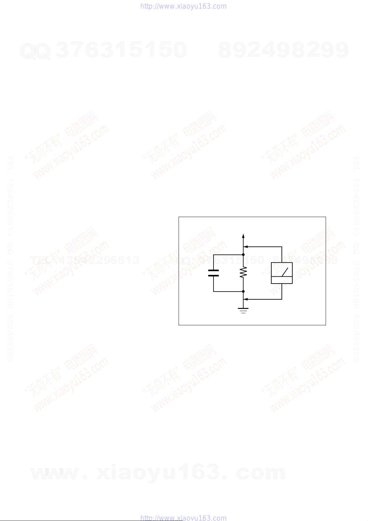
Leakage current can be measured by any one of three methods.
1. A commercial leakage tester, such as the Simpson 229 or RCA
WT -540A. Follow the manuf acturers’ instructions to use these
instruments.
2. A battery-operated A C milliammeter. The Data Precision 245
digital multimeter is suitable for this job.
3. Measuring the voltage drop across a resistor by means of a
VOM or battery-operated AC v oltmeter . The “limit” indication
is 0.75 V, so analog meters must have an accurate low-voltage
scale. The Simpson 250 and Sanwa SH-63Trd are examples
of a passive VOM that is suitable. Nearly all battery operated
digital multimeters that have a 2 V A C range are suitable. (See
Fig. A)
7
3
Q
Q
0.15 µF
9
8
To Exposed Metal
Parts on Set
5
1
3
6
2
1
5
1.5 k
4
0
Ω
9
8
9
8
2
2
9
4
AC
voltmete
(0.75 V)
8
9
2
9
9
TEL 13942296513 QQ 376315150 892498299
9
General
Power requirements
North American model: 120 V AC, 60 Hz
European and Russian models:
Australian model: 230 – 240 V AC, 50/60 Hz
Korean model: 220 V AC, 60 Hz
Thai model: 220 V AC, 50/60 Hz
Other models: 110 – 120 V, 220 – 240 V
Power consumption
North American model: 110 watts
European and Russian models:
Australian, Korean and Thai models:
Other models: 120 watts
Dimensions (w/h/d) (excl. speakers)
Mass (excl. speakers) Approx. 5.9 kg
Design and specifications are subject to change
without notice.
w
w
230 V AC, 50/60 Hz
AC, 50/60 Hz
Adjustable with voltage
selector
110 watts
0.3 watts (in Power Saving
Mode)
110 watts
Approx. 190 × 250 ×
301 mm
w
.
xia
o
y
Earth Ground
Fig. A. Using an AC voltmeter to check AC leakage.
SAFETY-RELATED COMPONENT WARNING!!
COMPONENTS IDENTIFIED BY MARK 0 OR DOTTED LINE
WITH MARK 0 ON THE SCHEMATIC DIAGRAMS AND IN
THE PARTS LIST ARE CRITICAL TO SAFE OPERATION.
REPLACE THESE COMPONENTS WITH SONY PARTS WHOSE
PART NUMBERS APPEAR AS SHOWN IN THIS MANUAL OR
IN SUPPLEMENTS PUBLISHED BY SONY.
ATTENTION AU COMPOSANT AYANT RAPPORT
LES COMPOSANTS IDENTIFIÉS PAR UNE MARQUE 0 SUR
LES DIAGRAMMES SCHÉMATIQUES ET LA LISTE DES
PIÈCES SONT CRITIQUES POUR LA SÉCURITÉ DE
FONCTIONNEMENT. NE REMPLACER CES COM- POSANTS
u
1
6
QUE PAR DES PIÈCES SONY DONT LES NUMÉROS SONT
DONNÉS DANS CE MANUEL OU D ANS LES SUPPLÉMENTS
PUBLIÉS PAR SONY.
3
À LA SÉCURITÉ!
.
c
o
m
2
HCD-DX2D
Ver. 1.2
7
Q
Q
TEL 13942296513 QQ 376315150 892498299
TEL
w
3
Laser component in this product is capable of emitting radiation
exceeding the limit for Class 1.
CAUTION
Use of controls or adjustments or performance of procedures
other than those specified herein may result in hazardous radiation
exposure.
Notes on chip component replacement
• Never reuse a disconnected chip component.
• Notice that the minus side of a tantalum capacitor may be
damaged by heat.
Flexible Circuit Board Repairing
• Keep the temperature of the soldering iron around 270 °C
during repairing.
• Do not touch the soldering iron on the same conductor of the
circuit board (within 3 times).
• Be careful not to apply force on the conductor when soldering
or unsoldering.
UNLEADED SOLDER
Boards requiring use of unleaded solder are printed with the lead-
13942296513
free mark (LF) indicating the solder contains no lead.
(Caution: Some printed circuit boards may not come printed with
the lead free mark due to their particular size)
: LEAD FREE MARK
Unleaded solder has the following characteristics.
• Unleaded solder melts at a temperature about 40 °C higher
than ordinary solder.
Ordinary soldering irons can be used but the iron tip has to be
applied to the solder joint for a slightly longer time.
Soldering irons using a temperature regulator should be set to
about 350 °C.
Caution: The printed pattern (copper foil) may peel away if
• Strong viscosity
Unleaded solder is more viscou-s (sticky, less prone to flow)
than ordinary solder so use caution not to let solder bridges
occur such as on IC pins, etc.
• Usable with ordinary solder
It is best to use only unleaded solder but unleaded solder may
also be added to ordinary solder.
• Abbreviation
AUS: Australian model
CND : Canadian model
E3 : 240 V AC Area in E model
E51 : Chilean and Peruvian models
KR : Korean model
RU : Russian model
w
w
SP : Singapore model
TH : Thai model
6
the heated tip is applied for too long, so be careful!
.
1
3
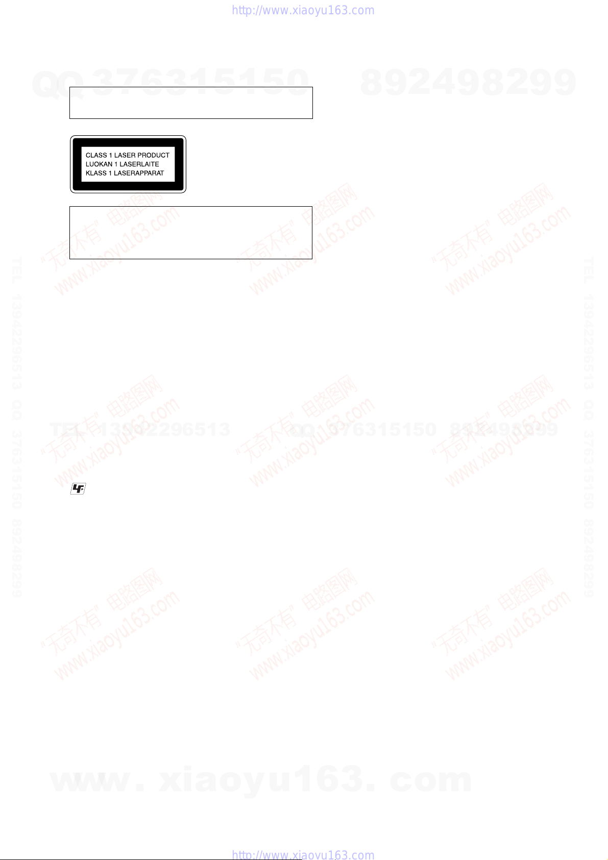
This appliance is classified as
a CLASS 1 LASER product.
The CLASS 1 LASER
PRODUCT MARKING is
located on the rear exterior.
xia
5
o
1
y
5
u
0
Q
Q
1
1. SERVICING NOTES ................................................ 4
2. GENERAL ................................................................... 7
3. DISASSEMBLY
3-1. Disassembly Flow ........................................................... 10
3-2. Top Cover, DC Fan .......................................................... 11
3-3. AMP Board, AV Board, Tuner (FM/AM) ....................... 11
3-4. MPEG Board ................................................................... 12
3-5. MPEG Holder .................................................................. 12
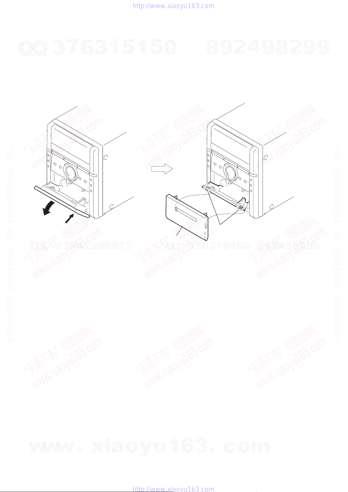
3-6. Panel (DVD) .................................................................... 13
3-7. DVD Loader (DVD Mechanism) .................................... 13
3-8. Front Panel Section ......................................................... 14
3-9. MAIN Board.................................................................... 14
3-10. Cassette Mechanism Deck (CMAL5Z220C) .................. 15
3-11. KEY Board ...................................................................... 15
3-12. Panel Cass (Cassette)....................................................... 16
4. TEST MODE ............................................................... 17
5. MECHANICAL ADJUSTMENTS......................... 18
6. ELECTRICAL ADJUSTMENTS .......................... 18
7. DIAGRAMS
7-1. Block Diagram — MPEG-1 Section — ......................... 22
7-2. Block Diagram — MPEG-2 Section — ......................... 23
7-3. Block Diagram — AUDIO Section —........................... 24
7-4. Block Diagram — PANEL/POWER Section — ............ 25
7-5. Printed Wiring Board — MAIN Section — ................... 26
7
3
7-6. Schematic Diagram — MAIN Section (1/3) — ............. 27
7-7. Schematic Diagram — MAIN Section (2/3) — ............. 28
7-8. Schematic Diagram — MAIN Section (3/3) — ............. 29
7-9. Printed Wiring Board — MPEG Section (Side A) — .... 30
7-10. Printed Wiring Board — MPEG Section (Side B) — .... 31
7-11. Schematic Diagram — MPEG Section (1/3) — ............ 32
7-12. Schematic Diagram — MPEG Section (2/3) — ............ 33
7-13. Schematic Diagram — MPEG Section (3/3) — ............ 34
7-14. Printed Wiring Board — KEY Section — ..................... 35
7-15. Schematic Diagram — KEY Section — ........................ 36
7-16. Printed Wiring Board — AV Section —......................... 37
7-17. Schematic Diagram — AV Section — ........................... 38
7-18. Printed Wiring Board — AMP Section — ..................... 39
7-19. Schematic Diagram — AMP Section —........................ 40
7-20. Printed Wiring Board
7-21. Schematic Diagram
7-22. Printed Wiring Board — POWER Section
7-23. Schematic Diagram — POWER Section
7-24. Printed Wiring Board
7-25. Schematic Diagram
8. EXPLODED VIEWS
8-1. Overall Section ................................................................ 56
8-2. Front Panel Section ......................................................... 57
8-3. Chassis Section ................................................................ 58
8-4. DVD Mechanism Deck Section ...................................... 59
6
3
9. ELECTRICAL PARTS LIST.................................. 60
4
8
3
6
— POWER Section (US, CND Model) — ..................... 41
— POWER Section (US, CND Model) — ..................... 42
(AEP, UK, RU, KR, AUS Model) — .............................. 43
(AEP UK, RU, KR, AUS Model) — ............................... 44
— POWER Section (E3, E51, SP, TH Model) —........... 45
— POWER Section (E3, E51, SP, TH Model) —........... 46
.
TABLE OF CONTENTS
0
5
1
5
1
c
o
2
9
9
9
8
m
2
8
4
2
9
8
9
2
9
9
9
TEL 13942296513 QQ 376315150 892498299
3
HCD-DX2D
Ver. 1.2
SECTION 1
SERVICING NOTES
7
Q
Q
NOTES ON HANDLING THE OPTICAL PICK-UP
BLOCK OR BASE UNIT
The laser diode in the optical pick-up block may suffer electrostatic
break-down because of the potential difference generated by the
charged electrostatic load, etc. on clothing and the human body.
During repair, pay attention to electrostatic break-down and also
use the procedure in the printed matter which is included in the
repair parts.
The flexible board is easily damaged and should be handled with
care.
NOTES ON LASER DIODE EMISSION CHECK
The laser beam on this model is concentrated so as to be focused on
the disc reflective surface by the objective lens in the optical pick-
TEL 13942296513 QQ 376315150 892498299
up block. Therefore, when checking the laser diode emission,
observe from more than 30 cm away from the objective lens.
DISC TRA Y LOCK
The disc tray lock function for the antitheft of an demonstration
disc in the store is equipped.
Procedure :
1. Press the ?/1 button to turn the set ON.
2. Press the DVD u button to select “DVD”
3. Set disc on the tray, press the x button and the Z button
simultaneously for five seconds.
4. The message “LOCKED” is displayed the tray is locked.
5. To release from this mode, press the x button and the Z
button simultaneously for five seconds again.
6. The message “UNLOCKED” is displayed and the tray is
unlocked.
TEL
Note: When “LOCKED” is displayed, the slot lock is not released by
turning power on/off with the ?/1 button.
3
13942296513
6
3
1
5
1
5
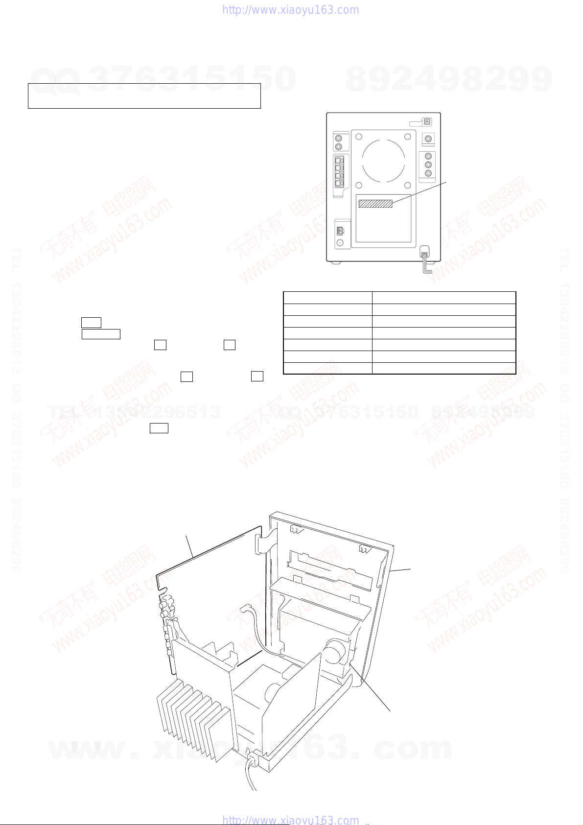
MODEL IDENTIFICATION
0
– Back Panel –
Model Power V oltage Indication
US, CND models 120 V AC, 60 Hz
AEP, UK, RU models 230 V AC, 50/60 Hz
AUS model 230 – 240 V AC, 50/60 Hz
KR model 220 V AC, 60 Hz
TH model 220 V AC, 50/60 Hz
E3, E51, SP models 110 – 120 V, 220 – 240 V AC, 50/60 Hz
•Abbreviation
AUS: Australian model
CND : Canadian model
E3 : 240 V AC Area in E model
Q
Q
E51 : Chilean and Peruvian models
KR : Korean model
RU : Russian model
SP : Singapore model
TH : Thai model
3
7
8
6
3
9
1
5
2
1
5
4
0
8
9
Power requirement
indication
4
2
9
8
2
9
8
9
2
9
9
TEL 13942296513 QQ 376315150 892498299
9
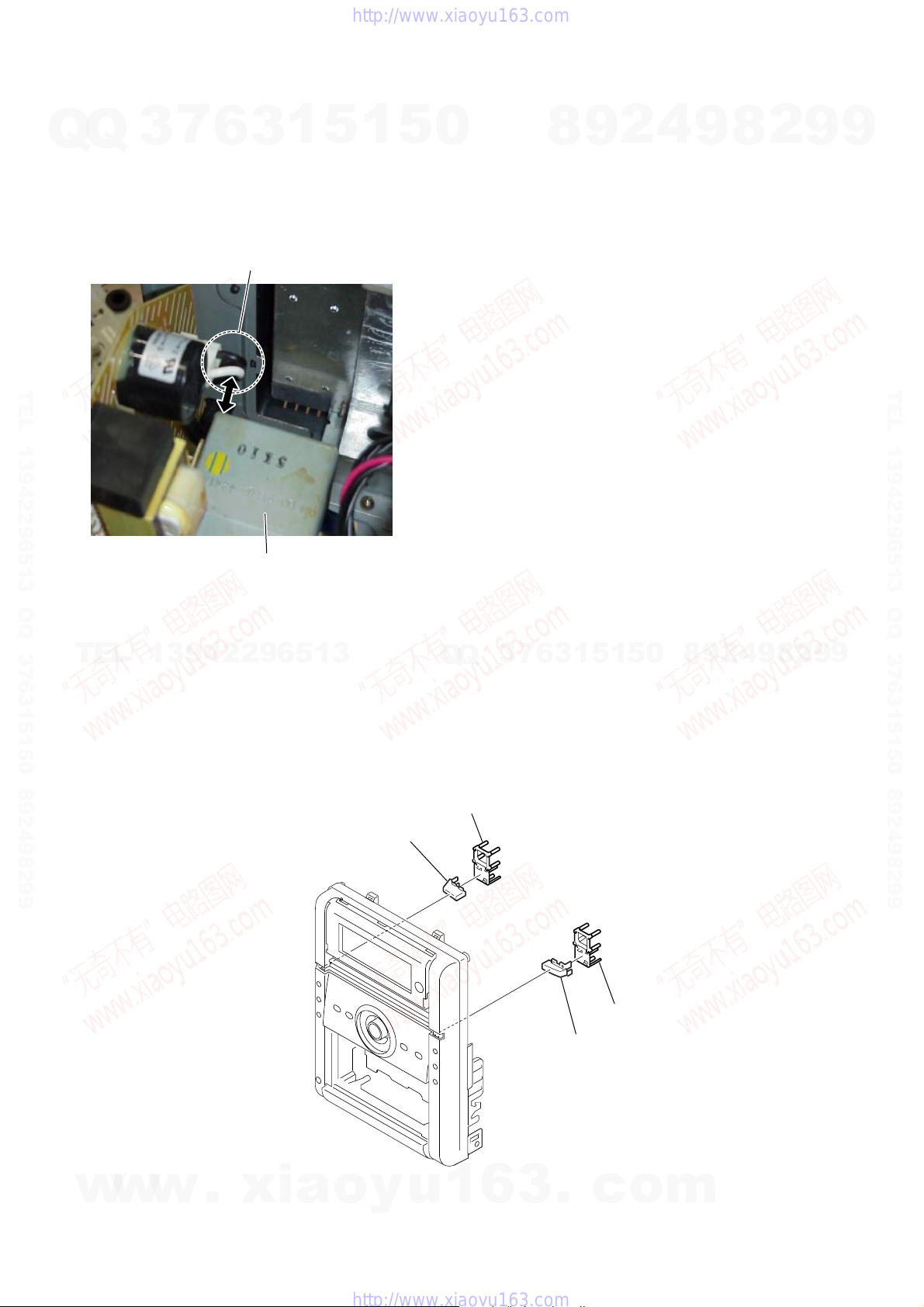
• SERVICE POSITION OF THE TAPE CASSETTE MECHANISM DECK
MAIN board
w
w
w
.
xia
o
y
u
1
6
3
Front Panel
Tape Cassette Mechanism Deck
(CMAL5Z220C)
.
c
o
m
4
HCD-DX2D
7
3
Q
TEL 13942296513 QQ 376315150 892498299
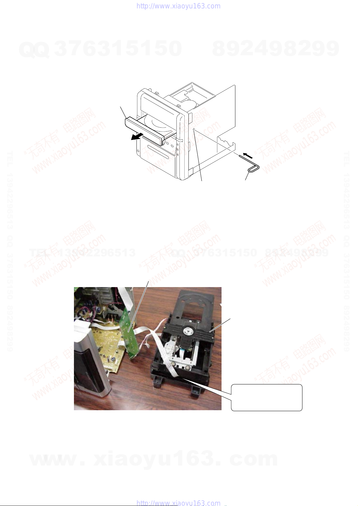
• HOW TO OPEN THE DVD TRAY MANUALLY
Q
Insert the stiff wire in the hole. The lock is released and the DVD tray opens.
6
3
DVD tray
1
5
1
5
0
hole
8
9
2
stiff wire
4
9
8
2
9
9
TEL 13942296513 QQ 376315150 892498299
TEL
13942296513
• SERVICE POSITION OF THE DVD MECHANISM DECK
MPEG board
Q
Q
3
7
6
3
0
5
1
5
1
DVD mechanism deck
Draw out the flexible board
of the DVD mechanism deck
from this position.
8
9
2
4
9
8
2
9
9
w
w
w
.
xia
o
y
u
1
6
3
.
c
o
m
5
HCD-DX2D
7
• CAUTION ON HANDLING POWER CORD (SAFETY STANDARD)
Q
Q
When you remove or replace the power cord,
(1) Fix the power cord to the POWER board with a binding strap as before.
(2) Check that the single-sheathed portion of the power cord does not contact the transformer
even when the single-sheathed portion is pushed toward the transformer with a 200-g force.
TEL 13942296513 QQ 376315150 892498299
3
6
single-sheathed portion
of the power cord
power transformer
3
1
5
1
5
0
8
9
2
4
9
8
2
9
9
TEL 13942296513 QQ 376315150 892498299
TEL
• PRECAUTION WHEN REPLACING THE CAP
Please apply the adhesive agent or attach the double-sided tape to the BASE KEY POWER when replacing the CAP KEY POWER.
Please apply the adhesive agent or attach the double-sided tape to the BASE KEY OPEN when replacing the CAP KEY OPEN.
13942296513
CAP KEY POWER
3
Q
Q
BASE KEY POWER
1
3
6
7
CAP KEY OPEN
0
5
1
5
BASE KEY OPEN
8
9
2
4
9
8
2
9
9
6
w
w
w
.
xia
o
y
u
1
6
3
.
c
o
m

SECTION 2
GENERAL
HCD-DX2D
This section is extracted
from instruction manual.
7
Q
Q
TEL 13942296513 QQ 376315150 892498299
3
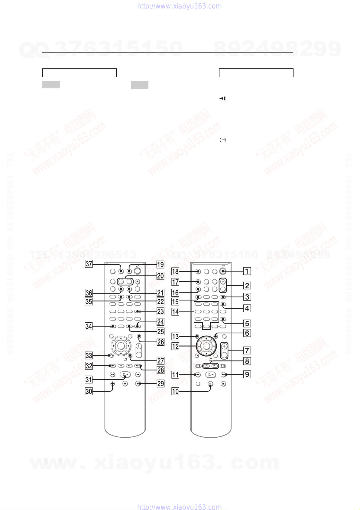
How to use this page
Use this page to find the lo ca tio n of buttons and other
parts of the system that are mentioned in the text.
Main unit
ALPHABETICAL ORDER
A – O P – Z
Cassette compartment qh (31)
CD SYNC 0 (31)
Disc tray 5 (14)
DISPLAY 9 (30, 37, 38, 39)
Display window 3
6
List of button locations and reference pages
3
1
5
1
5
0
PHONES jack qk
PLAY MODE wd (15, 19, 48)
PRESET EQ ws (33)
PROGRESSIVE wa (24)
Remote sensor 4
TUNER/BAND 7 (28, 29, 32)
TUNING +/– qs (28, 30)
TV w; (32, 42)
VOLUME control qj (42)
4
2
9
8
Illustration number
TUNER/BAND 7 (28, 29, 32)
RR
Name of button/part Reference page
BUTTON DESCRIPTIONS
?/1 (on/standby) 1 (11, 48)
TAPE N (play) 2 (31)
DVD NX (play/pause) 6 (14,
Z (open/close) 8 (14)
z REC PAUSE/START (record)
m/M (rewind/fast forward)
./> (go back/forward) qs
Z PUSH OPE N /CLOSE (eject)
x (stop) ql (12, 15, 24, 29, 31,
r
32, 43, 48)
qa (31, 34)
qs (15, 31)
(15, 31)
qd (31)
32, 34, 43, 48)
9
8
2
9
9
TEL 13942296513 QQ 376315150 892498299
TEL
13942296513
Q
Q
3
7
6
3
1
5
1
5
0
8
9
2
4
9
8
2
9
9
w
w
w
.
xia
o
y
u
1
6
3
.
c
o
m
7
HCD-DX2D
7
Q
Q
TEL 13942296513 QQ 376315150 892498299
3
Remote control
ALPHABETICAL ORDER
A – O
ANGLE 5 (22)
AUDIO 4 (21, 33)
CLEAR ef (19, 20, 25)
CLOCK/TIMER SELECT w;
(36, 37)
CLOCK/TIMER SET w; (13, 35,
36)
DIMMER ej (37)
DISPLAY qj (30, 37, 38, 39)
DVD eh (12, 13, 14, 17, 19, 24,
26, 31, 43)
ENTER qs wg (13, 16, 17, 19, 20,
22, 23, 25, 28, 35, 36, 42, 48)
FM MODE eg (30)
FUNCTION +/– 2 (12, 13, 14,
17, 19, 24, 26, 31, 43)
MENU 6 (16, 17)
MUTING wh (15, 30, 31)
Number buttons* qf (16, 17, 19,
20, 25, 40)
6
3
1
5
1
5
0
P – Z
PLAY MODE qg (15, 19)
PRESET + wk (28, 29)
PRESET – es (28, 29)
PRESET EQ wf (33)
REPEAT eg (18)
SEARCH 3 (20)
SLEEP qk (35)
SUBTITLE wd (22)
TAPE qh (31)
THEATRE SYNC ql (40)
TOP MENU qd (16)
TUNER/BAND wa (28, 29)
TUNER MEMORY ws (28)
TUNING + 9 (28, 30)
TUNING – qa (28, 30)
TV e; (40)
TV CH + wk (40)
TV CH – es (40)
TV/VIDEO qk (40)
TV VOL +/–* 7 (40)
VOLUME +/–* 7 (15, 30, 31,
35)
4
2
9
8
BUTTON DESCRIPTIONS
?/1 (on/standby) 1 (11, 35, 48)
TV ?/1 1 (40)
SLOW/SLOW y 8 (15)
M (fast forward) 9 (15, 31)
X (pause) 0 (15)
m (rewind) qa (15, 31)
M/m/</, qs (13, 15, 22, 42,
48)
DISPLAY wj (13, 22, 42, 48)
> (forward) wk (13, 15, 31, 35)
x (stop) wl (12, 15, 24, 31, 32,
34, 43)
H (play)* ea (14, 31, 43)
. (go back) es (13, 15, 31, 35)
O RETURN ed (17)
-/-- ef
*The H, number 5 and
VOLUME + (TV VOL +)
buttons have tactile dots. Use
the tactile dots as referenc es
when op erating the system.
9
8
2
9
9
TEL 13942296513 QQ 376315150 892498299
TEL
13942296513
Q
Q
3
7
6
3
1
5
1
5
0
8
9
2
4
9
8
2
9
9
8
w
w
w
.
xia
o
y
u
1
6
3
.
c
o
m

HCD-DX2D
7
Q
Q
TEL 13942296513 QQ 376315150 892498299
3
Setting the clock
Use buttons on the remote for the operation.
1
Press ?/1 to turn on the system.
2
Press CLOCK/TIMER SET.
3
Press . or > repeatedly to set the
hour.
4
Press ENTER.
5
Press . or > repeatedly to set the
minute.
6
Press ENTER.
The clock starts working.
To adjust the clock
1
Press CLOCK/TIMER SET.
2
Press . or > to select “CLOCK SET,”
then press ENTER.
3
Do the same procedures as step 3 to 6
above.
6
3
1
5
1
5
0
8
9
2
4
9
8
2
9
9
TEL 13942296513 QQ 376315150 892498299
Notes
The clock settings are canceled when you disconnect
the power cord or if a power failure occurs.
You cannot set the clock in Power Saving Mode
TEL
13942296513
(page 37).
Q
Q
3
7
6
3
1
5
1
5
0
8
9
2
4
9
8
2
9
9
w
w
w
.
xia
o
y
u
1
6
3
.
c
o
m
9
HCD-DX2D
Ver. 1.2
SECTION 3
DISASSEMBLY
7
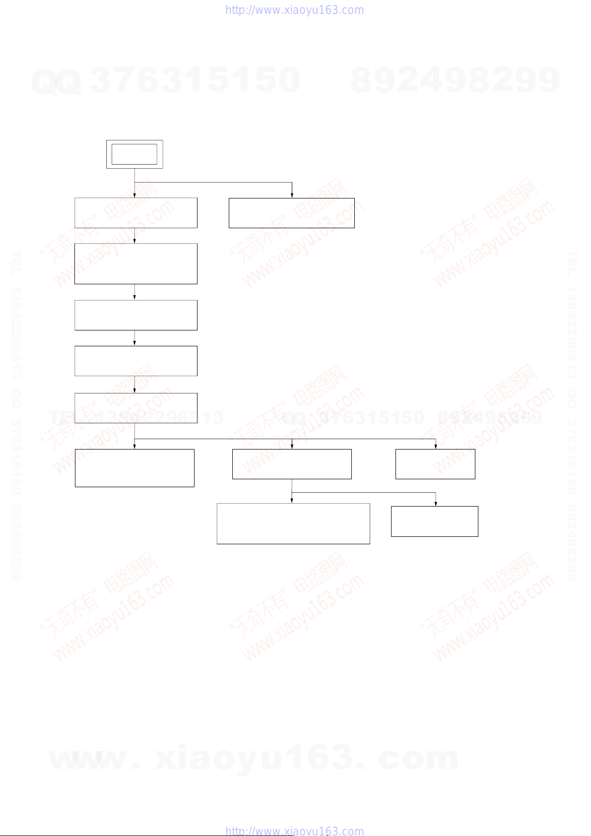
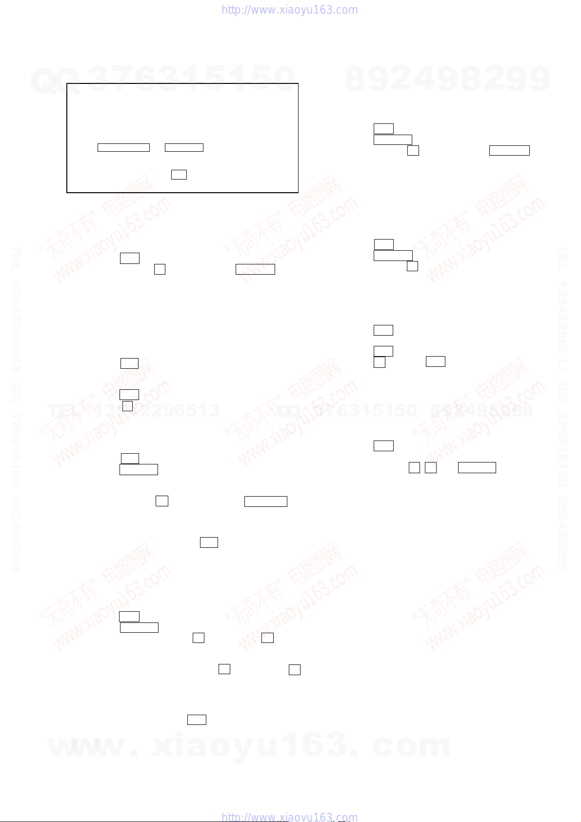
3-1. DISASSEMBLY FLOW
Q
Q
•This set can be disassembled in the order shown below.
TEL 13942296513 QQ 376315150 892498299
3
3-2. TOP COVER, DC FAN
3-3. AMP BOARD, AV BOARD,
TUNER (FM/AM)
3-4. MPEG BOARD
3-5. MPEG HOLDER
6
SET
(Page 11)
(Page 11)
(Page 12)
(Page 12)
3
1
5
1
5
0
3-12. PANEL CASS (CASSETTE)
(Page 16)
8
9
2
4
9
8
2
9
9
TEL 13942296513 QQ 376315150 892498299
TEL
3-6. PANEL (DVD)
(Page 13)
13942296513
3-7. DVD LOADER
(DVD MECHANISM)
(Page 13)
3
6
7
3
Q
Q
3-8. FRONT PANEL SECTION
3-10. CASSETTE MECHANISM DECK
(Page 14)
(CMAL5Z220C)
(Page 15)
1
0
5
1
5
3-9. MAIN BOARD
3-11. KEY BOARD
(Page 15)
8
(Page 14)
9
2
4
9
8
2
9
9
10
w
w
w
.
xia
o
y
u
1
6
3
.
c
o
m
HCD-DX2D
Ver. 1.1
Q
TEL 13942296513 QQ 376315150 892498299
Note: Follow the disassembly procedure in the numerical order given.
Q
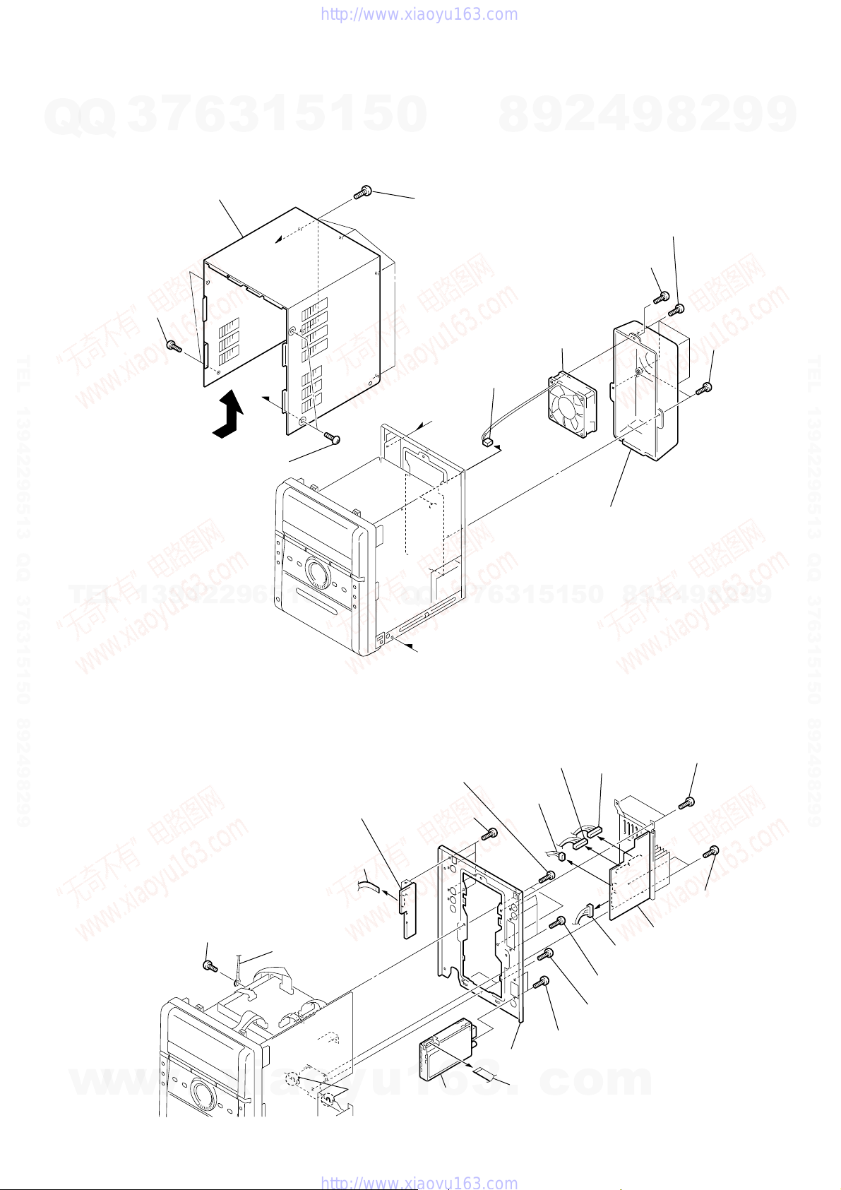
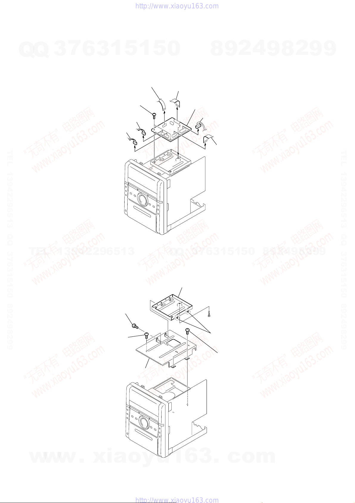
3-2. TOP COVER, DC FAN
2
(screw 3
3
two s
7
crews
×
6
5
8)
3
top cover
4
1
two s
(screw 3
crews
1
a
b
×
8)
5
1
5
0
3
(screw 3
five s
crews
×
8
connector
3P (CN350)
a
8
8)
4
2
9
7
(screw 3
q;
DC fan
9
9
four s
(screw 3
s
crew
×
qa
cover heat sink
crews
×
8)
8
8)
2
9
6
two s
(screw 3
9
crews
×
TEL 13942296513 QQ 376315150 892498299
8)
TEL
13942296513
3-3. AMP BOARD, AV BOARD, TUNER (FM/AM)
qd
wire (flat type)
16core (CN801) (AEP, UK, RU)
16core (CN801A) (EXCEPT AEP, UK, RU)
qa
screw
(screw 3
×
8)
qs
earth wire
qk
AV board
Q
Q
b
0
two screws
(screw 3
qj
four screws
(screw 3
7
3
×
8)
×
10)
5
1
3
6
4
connector
7P (CN102)
5
connector
3P (CN106)
w;
panel rear
0
5
1
3
10P (CN108)
9
(screw 3
8
two screws
(screw 3
qf
two screws
(screw 3
2
9
8
1
connector
6
5P (CN101)
(screw 3
7
connector
three screws
×
8)
×
×
8)
8
9
4
two screws
2
two screws
(screw 3
AMP board
10)
2
×
10)
×
9
10)
9
w
w
w
.
xia
ql
o
two claws
y
u
1
6
3
qh
tuner
qg
wire (flat type)
.
c
o
9core (EXCEPT AEP, UK)
11core (AEP, UK)
m
11
HCD-DX2D
7
3-4. MPEG BOARD
Q
Q
TEL 13942296513 QQ 376315150 892498299
3
6
1
3
7
two s
(screw 3
2
connector
5P (CN9)
1
connector
6P (CN10)
5
1
3
wire (flat type)
24core (CN7)
crews
×
8)
5
0
4
wire (flat type)
16core (CN2)
8
MPEG board
5
9P (CN3)
9
8
connector
6
wire (flat type)
12core (CN1)
2
4
9
8
2
9
9
TEL 13942296513 QQ 376315150 892498299
TEL
3-5. MPEG HOLDER
13942296513
1
s
crew
(screw 3
5
two s
crews
(screw 3
9
9
2
8
9
4
2
9
8
0
5
1
5
1
3
6
7
3
Q
Q
3
MPEG holder
×
8)
2
two hooks
×
8)
4
(screw 3
6
holder
two s
crews
×
8)
12
w
w
w
.
xia
o
y
u
1
6
3
.
c
o
m
HCD-DX2D
Ver. 1.2
7
3
Q
TEL 13942296513 QQ 376315150 892498299
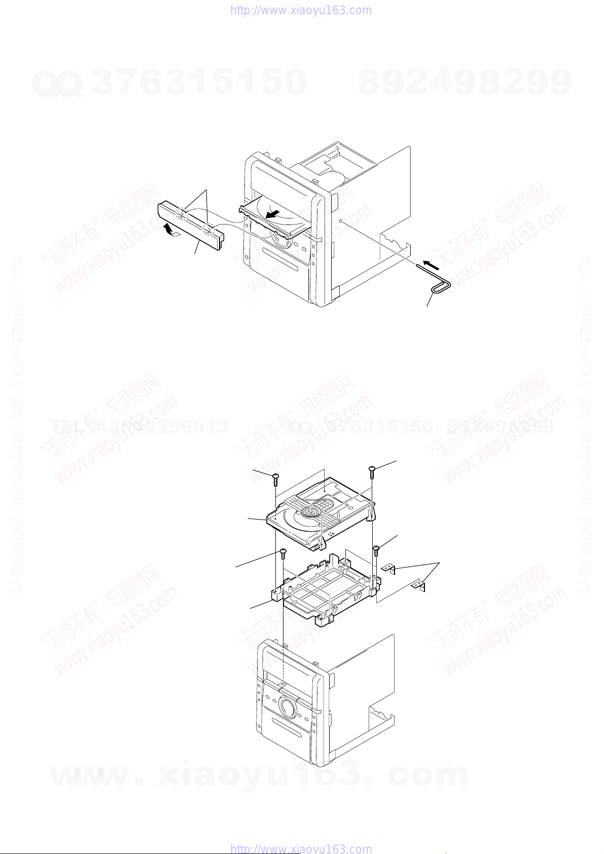
3-6. PANEL (DVD)
Q
6
3
3
4
panel (DVD)
1
two
5
claws
1
5
2
0
8
9
2
stiff wire
4
1
9
8
2
9
9
TEL 13942296513 QQ 376315150 892498299
3-7. DVD LOADER (DVD MECHANISM)
TEL
13942296513
1
two s
(screw 3
3
DVD loader
(DVD mechanism)
4
two s
(screw 3
7
holder DVD
crews
× 10
crews
× 10
9
9
2
8
9
4
2
9
8
0
5
1
5
1
3
6
7
3
Q
Q
2
two s
crews
× 10
)
)
(screw 3
5
two s
crews
(screw 3
)
×
10)
6
holder mecha rear
w
w
w
.
xia
o
y
u
1
6
3
.
c
o
m
13
HCD-DX2D
w
Ver. 1.1
7
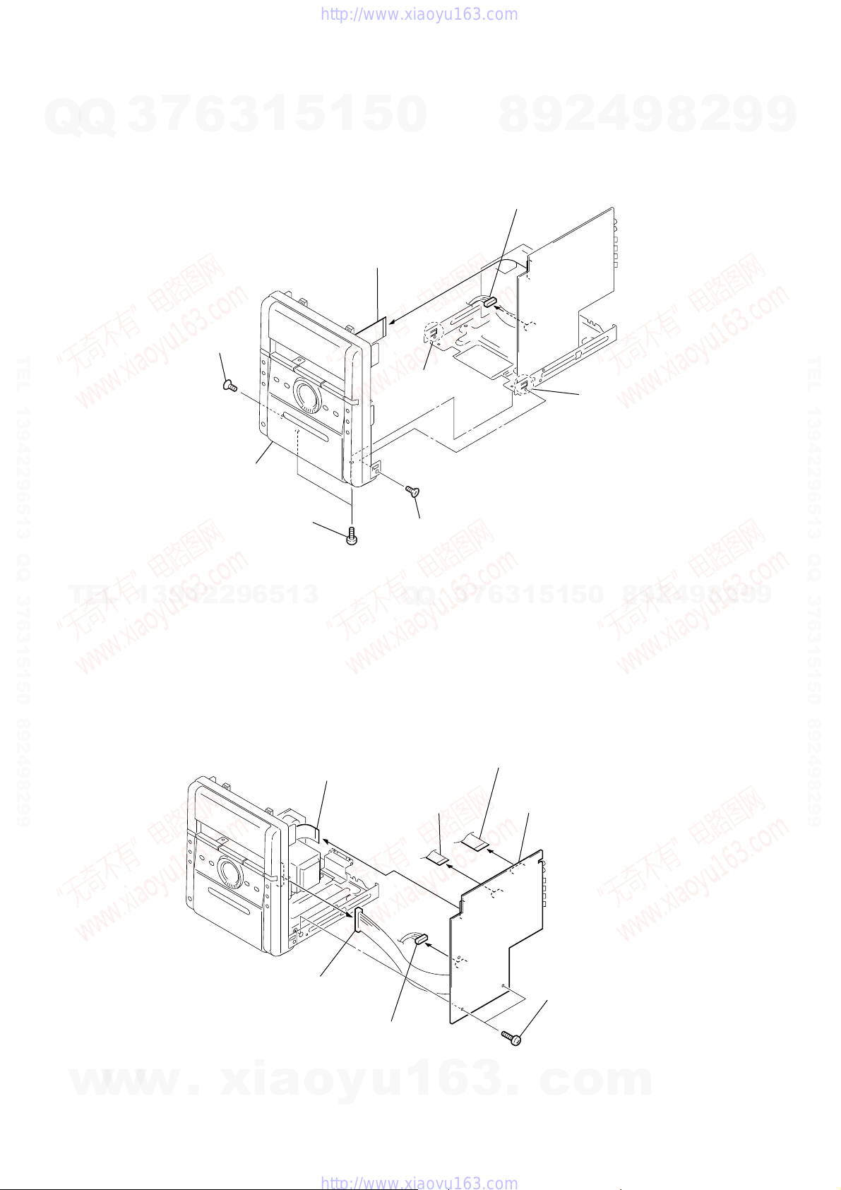
3-8. FRONT PANEL SECTION
Q
Q
TEL 13942296513 QQ 376315150 892498299
3
6
3
screw
(screw 3
8
front panel section
1
1
3
×
8)
two screws
(screw 3
×
10)
5
1
4
23core (CN501)
5
0
wire (flat type)
7
claw
2
screw
(screw 3
5
connector
8P (CN201)
×
8)
8
9
2
6
4
cla
9
8
2
9
9
TEL 13942296513 QQ 376315150 892498299
TEL
3-9. MAIN BOARD
13942296513
2
wire (flat type)
23core (CN501)
4
connector
11P (FW901)
3
8P (CN201)
Q
Q
5
wire (flat type)
12core (CN503)
connector
8
0
5
1
5
1
3
6
7
3
6
wire (flat type)
9core (CN203) (EXCEPT AEP, UK)
11core (CN203) (AEP, UK)
7
MAIN board
1
two screws
(screw 3
×
10)
9
2
4
9
8
2
9
9
14
w
w
w
.
xia
o
y
u
1
6
3
.
c
o
m
HCD-DX2D
7
3
Q
TEL 13942296513 QQ 376315150 892498299
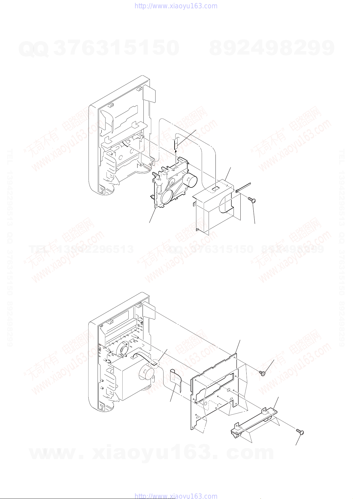
3-10. CASSETTE MECHANISM DECK (CMAL5Z220C)
Q
6
3
1
5
1
5
0
1
wire (flat type)
7core
8
4
2
9
3
cover cass deck DV2D
9
8
2
9
9
TEL 13942296513 QQ 376315150 892498299
TEL
13942296513
3-11. KEY BOARD
4
cassette mechanism deck
(CMAL5Z220C)
7
3
Q
Q
4
w
ire (flat type)
7core (CN602)
6
3
1
5
1
6
0
5
KEY board
2
four screws
(screw 3 × 10)
9
8
2
holder mecha front
9
4
2
3
ten screws
(screw 2.6 × 8)
8
2
9
9
w
w
w
.
xia
5
w
ire (flat type)
23core (CN601)
o
y
u
1
6
3
.
c
o
m
1
four screws
(screw 3 × 10)
15
HCD-DX2D
Ver. 1.2
7
3-12. PANEL CASS (CASSETTE)
Q
Q
TEL 13942296513 QQ 376315150 892498299
3
2
6
3
1
5
1
5
0
8
9
2
4
9
8
2
9
9
TEL 13942296513 QQ 376315150 892498299
TEL
1
13942296513
4
panel cass (cassette)
Q
Q
3
7
6
3
3
1
two claws
1
5
5
0
8
9
2
4
9
8
2
9
9
16
w
w
w
.
xia
o
y
u
1
6
3
.
c
o
m
SECTION 4
TEST MODE
HCD-DX2D
Ver. 1.1
7
Q
Q
TEL 13942296513 QQ 376315150 892498299
TEL
3
Note 1:Regarding the notification symbol “R”
Because the number of the operating buttons of this product are
limited, some operations require use of the operating buttons of
the remote commander. When a specific operation requires use
of the operating buttons of the remote commander, “R” is added
to the specific operating procedure in this manual. Example
MENU/NO “R” The MENU/NO button of remote commander .
Note 2:Incorrect operations may be performed if the test mode is not
entered properly.
In this case, press the ?/1 button to turn the power off, and
retry to enter the test mode.
COLD RESET
• The cold reset clears all data including preset data stored in
the RAM to initial conditions. Execute this mode when
returning the set to the customers.
Procedure:
1. Press the ?/1 button to turn the set ON.
2. Press three buttons x , [PLAY MODE] and DVD u simul-
taneously.
3. The message “COLD RESET” is displayed and the set is reset.
TUNER STEP CHANGE
(EXCEPT FOR AEP, UK and Russian models)
•A step of AM channels can be changed over between 9 kHz
and 10 kHz.
Procedure:
1. Press the ?/1 button to turn the set ON.
2. Select the function “TUNER”, and press [TUNER/BAND]
button to select the BAND “AM”.
3. Press the ?/1 button to turn the set OFF.
4. Press the x and [TUNER/BAND] buttons simultaneously,
13942296513
and thus the channel step is changed over.
SHIP RESET
Procedure:
1. Press the ?/1 button to turn the set ON.
2. Press the DVD u button to select “DVD”
3. Remove the disc.
4. The message “NO DISC” is displayed.
5. Press three buttons x , [PLAY MODE] and TAPE N si-
multaneously.
6. The message “SHIP RESET” is displayed and the set is reset.
The DVD function is activated.
7. T o exit from this mode, press the ?/1 button and pull out the
AC plug.
6
3
1
5
1
5
0
Q
Q
PANEL TEST MODE
•This mode is used to check the software version, FL, LED
Procedure:
1. Press the ?/1 button to turn the set ON.
2. Press the DVD u button to select “DVD”
3. Press three bottons x , [PRESET EQ] and T APE N simul-
4. When the panel test mode is activated, all segments are turned
VERSION DISPLAY
•This mode is used check the model, destination, software
Procedure:
1. Press the ?/1 button to turn the set ON.
2. Press the DVD u button to select “DVD”
3. Press three buttons x , [PRESET EQ] and [TV] simultaneous-
DVD COLOR SYSTEM CHANGE OVER
•The color system can be changed over NTSC or PAL.
Procedure:
1. Press the ?/1 button to turn the set ON.
2. Set the function to “DVD”.
3. Press the ?/1 button to turn the set OFF.
4. Press the x button and ?/1 button simultaneously. The set
5. The message “COLOR PAL” or “COLOR NTSC” will be
7
3
CD Repeat 5 Times Limit Release Mode
Procedure:
1. Press the ?/1 button to turn the set ON.
2. Set the function to “DVD”.
3. Press three buttons x , Z , and DVD u simultaneously.
4. The repeat all mark blinks and then repeat 5 times limit is
4
2
9
8
and KEY.
taneously.
on.
version.
ly, the model and destination are displayed.
will power on automatically.
displayed on the fluorescent indicator tube. The color system
is changed over.
6
released.
3
1
5
1
5
0
9
8
9
2
8
4
2
9
8
9
2
9
9
9
TEL 13942296513 QQ 376315150 892498299
DISC TRA Y LOCK
The disc tray lock function for the antitheft of an demonstration
disc in the store is equipped.
Procedure :
1. Press the ?/1 button to turn the set ON.
2. Press the DVD u button to select “DVD”
3. Set disc on the tray, press the x button and the Z button
simultaneously for five seconds.
4. The message “LOCKED” is displayed the tray is locked.
5. To release from this mode, press the x button and the Z
button simultaneously for five seconds again.
6. The message “UNLOCKED” is displayed and the tray is
unlocked.
Note: When “LOCKED” is displayed, the slot lock is not released by
turning power on/off with the ?/1 button.
w
w
w
.
xia
o
y
u
1
6
3
.
c
o
m
17
HCD-DX2D
SECTION 5
MECHANICAL ADJUSTMENTS
SECTION 6
ELECTRICAL ADJUSTMENTS
Precaution
Q
Q
1. Clean the following parts with a denatured alcohol-moistened
swab:
record/playback heads pinch rollers
erase head rubber belts
capstan idlers
2. Demagnetize the record/playback head with a head demagnetizer.
3. Do not use a magnetized screwdriver for the adjustments.
4. After the adjustments, apply suitable locking compound to
the parts adjusted.
5. The adjustments should be performed with the rated power
supply voltage unless otherwise noted.
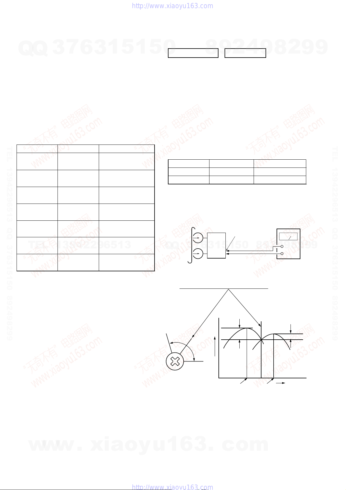
Torque Measurement
TEL 13942296513 QQ 376315150 892498299
Mode
FWD
FWD
back tension
REV
REV
back tension
FF/REW
FWD tension
TEL
REV tension
7
3
13942296513
6
Torque meter Meter reading
CQ-102C
CQ-102C
CQ-102RC
CQ-102RC
CQ-201B
CQ-403A
CQ-403R
1
3
2.94 – 7.84 mN • m
(31 to 71 g • cm)
(0.43 – 0.98 oz • inch)
0.15 – 0.59 mN • m
(2 to 6 g • cm)
(0.02 – 0.08 oz • inch)
2.94 – 7.84 mN • m
(30 to 79 g • cm)
(0.42 – 1.11 oz • inch)
0.15 – 0.59 mN • m
(2 to 6 g • cm)
(0.03 – 0.08 oz • inch)
6.86 – 17.64 mN • m
(71 to 143 g • cm)
(0.98 – 2.49 oz • inch)
9.8 mN • m or more
(100 g • cm or more)
(1.4 oz • inch or more)
9.8 mN • m or more
(100 g • cm or more)
(1.4 oz • inch or more)
5
1
5
0
DECK SECTION 0 dB=0.775V
1. Demagnetize the record/playback head with a head
demagnetizer.
2. Do not use a magnetized screwdriver for the adjustments.
3. After the adjustments, apply suitable locking compound to
the parts adjusted.
4. The adjustments should be performed with the rated power
supply voltage unless otherwise noted.
5. The adjustments should be performed in the order given in
this service manual. (As a general rule, playback circuit
adjustment should be completed before performing recording
circuit adjustment.)
6. The adjustments should be performed for both L-CH and RCH.
7. Switches and controls should be set as follows unless otherwise
specified.
P-4-A100
WS-48B
[Record/Playback Head Azimuth Adjustment]
Procedure:
1. Mode : Playback
test tape
P-4-A100
(10kHz, –10dB)
7
3
Q
Q
2. Turn the adjustment screw and check output peaks. If the peaks
do not match for L-CH and R-CH, turn the adjustment screw
so that outputs match within 1 dB of peak.
8
6
3
2
9
Signal Used forTape
10 kHz, –10 dB
3 kHz, 0 dB
MAIN board
JK102
speaker terminal
set
1
5
1
5
4
9
Azimuth Adjustment
Tape Speed Adjustment
9
8
0
8
level meter
4
2
2
+
9
–
8
9
2
9
9
TEL 13942296513 QQ 376315150 892498299
9
18
w
w
w
.
xia
L-CH
peak
R-CH
6
peak
3
screw
position
o
y
u
1
output
level
.
within
1 dB
c
L-CH
peak
o
R-CH
peak
m
within 1dB
screw
position

U2
IC7
IC4
IC6
24
23
1
2
CN7 Pin
wf
(GND)
CN7 Pin
8
(V-RF)
CN7
— MPEG Board (SIDE A) —
HCD-DX2D
Ver. 1.2
Q
TEL 13942296513 QQ 376315150 892498299
3. Mode: Playback
Q
test tape
P-4-A100
(10kHz, –10dB)
4. After the adjustments, apply suitable locking compound to
Adjustment Location: Record/Playback/Erase Head
TEL
7
3
the parts adjusted.
6
set
Waveform of oscilloscope
in phase 45
good
13942296513
1
3
MAIN board
JK102
speaker terminal
L
R
°
90
°
5
135
1
oscilloscope
°
180
wrong
5
°
0
Q
Q
DVD SECTION
[RF Level Check]
Check the RF level when optical pick-up block is replaced.
Connection:
Procedure:
1. Connect an oscilloscope to CN7 pin 8 (V-RF) and CN7 pin
2. Turn the power on.
3. Set the test disc on the tray and press DVDu button to
4. Observe the waveform of the oscilloscope, and check that the
[Test Disc List and Specified Value]
Use the following test disc on adjustment.
CD YEDS-18 (Part No.: 3-702-101-01)
DVD SL (Single Layer)
NTSC :HLX-503 (Part No.: J-6090-069-A)
PAL :HLX-506 (Part No.: J-6090-077-A)
7
3
DVD DL (Dual Layer)
NTSC :HLX-501 (Part No.: J-6090-071-A)
PAL :HLX-507 (Part No.: J-6090-078-A)
Note: Do not use existing test disc for DVD.
4
2
9
8
MPEG board
8
CN7 pin
CN7 pin
wf (GND) on the MPEG board.
playback.
RF level is satisfied to specified value.
PATD-012 (Part No.: 4-225-203-01)
HLX-504 (Part No.: J-6090-088-A)
5
1
3
6
HLX-505 (Part No.: J-6090-089-A)
(V-RF)
wf
(GND)
TEST DISC Specified Value
8
0
5
1
9
9
8
2
2
oscilloscope
+
–
0.57 to 1.1 Vp-p
8
9
4
0.58 to 1.23 Vp-p
9
2
9
9
TEL 13942296513 QQ 376315150 892498299
9
Note: Refer to “3-12. PANEL CASS (CASSETTE)” (see page 16)
[Tape Speed Check]
Procedure:
1. Turn the power on.
w
2. Insert the WS-48B into deck.
3. Press the TAPE N button of deck.
4. Check the reading of frequency counter becomes 3000 ± 90
Hz.
Sample Value of Wow and flutter
w
w
W.RMS (JIS) less than 0.3%
(test tape: WS-48B)
adjustment screw
.
xia
o
y
u
1
Checking Location: MPEG board (Side A)
6
3
.
c
o
m
19
HCD-DX2D
C
B
These are omitted.
E
Q
B
These are omitted.
CE
B
These are omitted.
CE
Q
Ver. 1.2
SECTION 7
DIAGRAMS
7
Q
Q
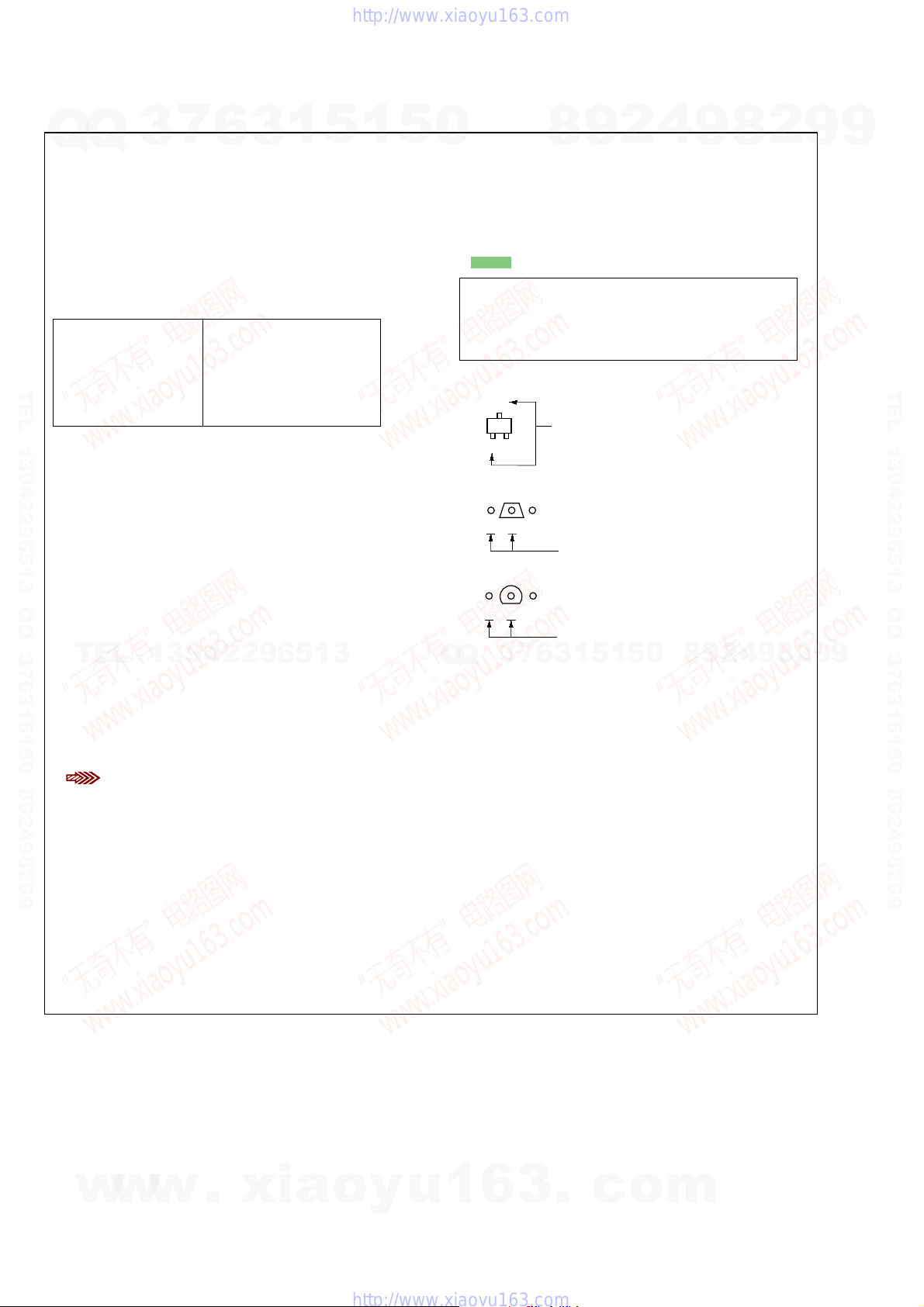
THIS NOTE IS COMMON FOR PRINTED WIRING BOARDS AND SCHEMATIC DIAGRAMS.
(In addition to this, the necessary note is printed in each block.)
For Schematic Diagrams.
Note:
• All capacitors are in µF unless otherwise noted. (p: pF)
50 WV or less are not indicated except f or electrolytics and
tantalums.
• All resistors are in Ω and 1/
specified.
• f : internal component.
• C : panel designation.
Note:
The components identified by mark 0 or dotted line with mark 0 are
TEL 13942296513 QQ 376315150 892498299
critical for safety.
Replace only with part
number specified.
• A : B+ Line.
• B : B– Line.
•Voltages and waveforms are dc with respect to ground
under no-signal (detuned) conditions.
– MPEG Section –
No mark: DVD STOP
– Other Section –
No mark: FM
( ) : TAPE REC
•Voltages are taken with a VOM (Input impedance 10 MΩ).
Voltage v ariations ma y be noted due to normal production
tolerances.
•Waveforms are taken with a oscilloscope.
Voltage v ariations ma y be noted due to normal production
tolerances.
TEL
• Circled numbers refer to waveforms.
• Signal path.
F : AUDIO
d : TUNER
j : PB (TAPE)
a : REC (TAPE)
J : DVD/CD (AUDIO)
I : DVD/CD (DIGITAL)
h : TV IN
L : VIDEO
g : CD (RF)
q : R,G,B
r : COMPONENT
E : Y
•Abbreviation
AUS: Australian model
CND : Canadian model
E3 : 240 V AC Area in E model
E51 : Chilean and Peruvian models
KR : Korean model
RU : Russian model
SP : Singapore model
TH : Thai model
3
13942296513
: DVD (RF)
6
4
W or less unless otherwise
Note:
Les composants identifiés
par une marque 0 sont critiques pour la sécurité.
Ne les remplacer que par une
piéce portant le numéro
spécifié.
3
1
5
1
5
0
For Printed Wiring Boards.
Note:
• X : parts extracted from the component side.
• Y : parts extracted from the conductor side.
• f : internal component.
• : Pattern from the side which enables seeing.
Caution:
Parts face side: Parts on the parts face side seen from
(Side A) the parts face are indicated.
Pattern face side: Parts on the pattern face side seen from
(Side B) the pattern face are indicated.
• Indication of transistor.
6
7
3
Q
Q
8
3
9
1
5
1
2
5
4
0
9
8
9
8
2
4
2
9
8
9
2
9
9
TEL 13942296513 QQ 376315150 892498299
9
w
w
20
w
.
xia
o
y
u
1
6
3
.
c
o
m
)
HCD-DX2D
Ver. 1.1
• Circuit Boards Location
Q
TEL 13942296513 QQ 376315150 892498299
Q
3
KEY board
HP board
7
6
3
AV board (AEP,UK,RU)
1
5
AV board (EXCEPT AEP, UK, RU
1
MAIN board
5
0
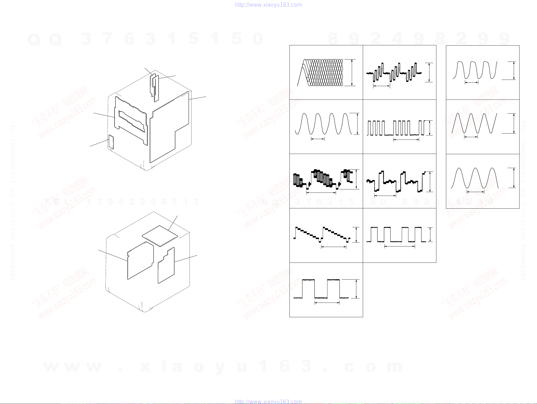
•Waveforms
– MPEG Board –
1
U2 <zbm (RFP)
200 mV/DIV, 100 ns/DIV
2
U2 <zvv (GCLX)
37 ns
1 V/DIV, 20 ns/DIV
3
U2 <zb/ (CVBS/C)
8
1000 mVp-p
9
4.1 Vp-p
1: AEP, UK, RU: S801 – COMPONENT
*
2: AEP, UK, RU: S801 – EURO AV
*
2
5
U2 <zbc (C/B/U) *1
500 mV/DIV, 20
5
U2 <zbc (C/B/U)
(AEP,UK,RU)
500 mV/DIV, 20
6
U2
4
H
µ
s/DIV
*
µ
s/DIV
<zbz (Y/R/V) *1
9
1.1 Vp-p
2
592 mVp-p
H
– MAIN Board –
8
7
1 V/DIV, 10
8
1 V/DIV, 50 ns/DIV
9
2
IC501 ej (XT2)
IC501 r; (X2)
Q344 (collector)(TAPE REC)
30.5 µs
µ
s/DIV
119 ns
9
9
4.1 Vp-p
3.6 Vp-p
TEL 13942296513 QQ 376315150 892498299
T
E
L
POWER board
1
3
9
4
2
2
9
6
5
MPEG board
1
3
AMP board
Q
Q
H
6
7
3
500 mV/DIV, 20
4
U2 <zv, (CVBS/G/Y) *1
1 V/DIV, 20
4
U2 <zv, (CVBS/G/Y)
(AEP,UK,RU)
500 mV/DIV, 20
µ
s/DIV
µ
s/DIV
µ
s/DIV
H
3
*
H
2
2 Vp-p
5
1
2 Vp-p
640 mVp-p
H
0
5
1
500 mV/DIV, 20
6
U2 <zbz (Y/R/V)
(AEP,UK,RU)
500 mV/DIV, 20
µ
s/DIV
µ
s/DIV
0.9 Vp-p
9
4
2
9
8
2
*
H
530 mVp-p
20 V/DIV, 5
8
11.8 µs
2
µ
s/DIV
9
10.9 Vp-p
9
HCD-DX2D
w
w
w
.
x
i
a
o
y
u
1
6
3
2121
.
c
o
m
 Loading...