

Sony HCD-DH7BT - Dvd Receiver For Cmtdh7bt Micro, HCD-DH3, HCD-DH5BT System Service Manual
HCD-DH3/DH5BT/DH7BT
Q
Q
3
7
6
3
1
5
1
5
0
SERVICE MANUAL
Ver. 1.2 2007.10
TEL 13942296513 QQ 376315150 892498299
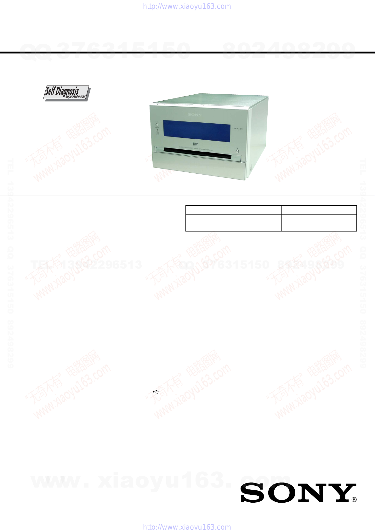
• HCD-DH3 is the amplifier, USB, disc player
and tuner section in CMT-DH3.
• HCD-DH5BT is the amplifier, bluetooth, USB,
disc player and tuner section in CMT-DH5BT.
• HCD-DH7BT is the amplifier, bluetooth, disc
player and tuner section in CMT-DH7BT.
• This system incorporates Dolby*
Digital and the DTS** Digital
Surround System.
* Manufactured under license from Dolby
Laboratories.
“Dolby” and the double-D symbol are
trademarks of Dolby Laboratories.
** “DTS” is a registered trademark of DTS,
Inc. and “DTS 2.0 + Digital Out” is a
trademark of DTS, Inc.
• U.S. and foreign patents licensed from
TEL
13942296513
Dolby Laboratories.
®
• DivX
is a video file compression
technology, developed by DivX, Inc.
DivX, DivX Certified, and associated
logos are trademarks of DivX, Inc. and
are used under license.
• The Bluetooth word mark and logos
are owned by the Bluetooth SIG, Inc.
and any use of such marks by Sony
Corporation is under license. Other
trademarks and trade names are those
of their respective owners.
• “WALKMAN” and “WALKMAN”
logo are registered trademarks of Sony
Corporation.
• MICROVAULT is a trademark of Sony
Corporation.
• ATRAC, ATRAC3, ATRAC3plus and
their logos are trademarks of Sony
Corporation.
• MPEG Layer-3 audio coding
technology and patents licensed from
Fraunhofer IIS and Thomson.
• The XM name and related logos are
registered trademarks of XM Satellite
Radio Inc.
• (c) 2006 SIRIUS Satellite Radio Inc.
“SIRIUS” and the SIRIUS dog logo
are registered trademarks of SIRIUS
Satellite Radio Inc.
TM
and ® marks are omitted in this
•
manual.
Photo: HCD-DH3
Model Name Using Similar Mechanism NEW
DVD Mechanism Type CDM86-DVBU101
Optical Pick-up Block Name KHM-313CAB
– HCD-DH7BT –
AUDIO POWER SPECIFICATIONS POWER
OUTPUT AND TOTAL HARMONIC
DISTORTION:
With 6 ohm loads, both channels driven, from
120 − 10,000 Hz; rated 50 watts per channel
channel minimum RMS power, with no more than
10% total harmonic distortion from 250 milliwatts
to rated output.
Amplifier section
DIN power output (rated):
Except Chinese model:
40 W + 40 W (6 ohms at 1 kHz, DIN)
Chinese model:
35 W + 35 W (6 ohms at 1 kHz, DIN)
Continuous RMS power output (reference):
Except Chinese model:
50 W + 50 W (6 ohms at 1 kHz, 10% THD)
Chinese model:
45 W + 45 W (6 ohms at 1 kHz, 10% THD)
Inputs:
AUDIO IN (stereo mini jack):
Voltage 620 mV, impedance 47 kilohms
MIC (mini jack) (HCD-DH3/DH5BT):
Sensitivity 0.8 mV, impedance 10 kilohms
(USB) port (HCD-DH3/DH5BT):
Type A, maximum current 500 mA
Outputs:
DIGITAL OUT (square optical connector jack):
Wavelength 660 nm
VIDEO OUT (phono jack):
Max. output level 1 Vp-p, unbalanced, Sync.
negative load impedance 75 ohms
COMPONENT VIDEO OUT:
Y: 1 Vp-p, 75 ohms
P
P
S VIDEO OUT (4-pin/mini-DIN jack):
Y: 1 Vp-p, unbalanced, Sync. negative
C: 0.286 Vp-p, load impedance 75 ohms
Q
Q
B/CB
: 0.7 Vp-p, 75 ohms
R/CR
: 0.7 Vp-p, 75 ohms
3
7
2
9
8
SPECIFICATIONS
1
5
1
3
6
4
9
8
2
9
US Model
HCD-DH7BT
Canadian Model
AEP Model
HCD-DH5BT
E Model
Australian Model
Chinese model
HCD-DH3/DH5BT
PHONES (stereo mini jack):
5
more
Bluetooth section (HCD-DH5BT/DH7BT)
Communication system:
Bluetooth Standard version 2.0
Output:
Bluetooth Standard Power Class 2
Maximum communication range:
Line of sight approx. 10 m
Frequency band:
2.4 GHz band (2.4000 GHz − 2.4835
GHz)
Modulation method:
FHSS
Compatible Bluetooth profiles
A2DP (Advanced Audio Distribution
Profile)
AVRCP (Audio Video Remote
Control Profile)
Supported codecs:
Receive: SBC (Sub Band Codec), MP3
Transmit: SBC (Sub Band Codec)
1)
The actual range will vary depending
on factors such as obstacles between
devices, magnetic fields around a
microwave oven, static electricity,
reception sensitivity, antenna’s
performance, operating system,
software application, etc.
2)
Bluetooth standard profiles indicate the
purpose of Bluetooth communication
between devices.
accepts headphones of 8 ohms or
9
8
0
9
4
2
– Continued on next page –
8
2)
2
1)
:
9
DVD RECEIVER
9
TEL 13942296513 QQ 376315150 892498299
9
w
w
9-887-629-03
2007J05-1
© 2007.10
w
.
xia
Sony Corporation
Personal Audio Division
Published by Sony Techno Create Corporation
o
y
u
1
6
3
.
c
o
m
HCD-DH3/DH5BT/DH7BT
Ver. 1.2
USB section (HCD-DH3/DH5BT)
Suppor ted bit rate:
Q
Q
MP3 (MPEG 1 Audio Layer-3):
32 − 320 kbps, VBR
ATRAC: 48 − 352 kbps
(ATRAC3plus), 66/105/132 kbps
(ATRAC3)
WMA: 32 − 192 kbps, VBR
AAC: 48 − 320 kbps
Sampling frequencies:
MP3 (MPEG 1 Audio Layer-3):
32/44.1/48 kHz
ATRAC: 44.1 kHz
WMA: 44.1 kHz
AAC: 44.1 kHz
Disc player section
System:
Compact disc and digital audio and video
system
Laser:
TEL 13942296513 QQ 376315150 892498299
Laser Diode Properties:
Emission duration: continuous
Laser Output*: Less than 1000 µW
* This output is the value measurement at a
distance of 200 mm from the objective lens
surface on the Optical Pick-up Block with
7 mm aperture.
Semiconductor laser:
(DVD: λ=650 nm, CD: λ=790 nm)
Frequency response:
DVD (PCM 48 kHz): 2 Hz − 22 kHz (±1dB)
CD: 2 Hz − 20 kHz (±0.5 dB)
Video color system format:
US and Canadian models: NTSC
European and Russian models: PAL
Other models: NTSC and PAL
3
7
6
3
Tuner section
FM stereo, FM/AM superheterodyne tuner
1
5
1
5
FM tuner section
Tuning range:
US and Canadian models:
87.5 − 108.0 MHz (100 kHz step)
Other models:
87.5 − 108.0 MHz (50 kHz step)
Antenna:
FM lead antenna
Antenna terminals:
75 ohms unbalanced
Intermediate frequency:
10.7 MHz
AM tuner section
Tuning range:
US and Canadian models:
530 − 1,710 kHz (with the interval set at
10 kHz)
531 − 1,710 kHz (with the interval set at
9 kHz)
European and Russian models:
531 − 1,602 kHz
(with the interval set at 9 kHz)
Other models:
530 − 1,710 kHz (with the interval set at
10 kHz)
531 − 1,602 kHz (with the interval set at
9 kHz)
Antenna:
AM loop antenna
Antenna terminals:
External antenna terminal
Intermediate frequency:
450 kHz
0
General
Power requirements:
9
8
Power consumption:
Dimensions (w/h/d) (Approx.):
Mass (Approx.):
Design and specifications are subject to change
without notice.
4
2
US and Canadian models: 120 V AC, 60 Hz
Taiwan model: 120 V AC, 50/60 Hz
Thai model: 220 V AC, 50/60 Hz
Other models: 220 − 240 V AC, 50/60 Hz
HCD-DH7BT: 40 W
HCD-DH3/DH5BT: 45 W
190 × 141 × 273 mm
2.8 kg
9
8
2
9
9
TEL 13942296513 QQ 376315150 892498299
Notes on chip component replacement
• Never reuse a disconnected chip component.
TEL
• Notice that the minus side of a tantalum capacitor may be
damaged by heat.
Flexible Circuit Board Repairing
• Keep the temperature of the soldering iron around 270 ˚C
during repairing.
• Do not touch the soldering iron on the same conductor of the
circuit board (within 3 times).
• Be careful not to apply force on the conductor when soldering
or unsoldering.
CAUTION
Use of controls or adjustments or performance of procedures
other than those specified herein may result in hazardous radiation
exposure.
This appliance is classified as a CLASS 1
LASER product. This marking is located
on the rear exterior.
SAFETY-RELATED COMPONENT WARNING!!
COMPONENTS IDENTIFIED BY MARK 0 OR DOTTED LINE
WITH MARK 0 ON THE SCHEMATIC DIAGRAMS AND IN
THE PARTS LIST ARE CRITICAL TO SAFE OPERATION.
w
REPLACE THESE COMPONENTS WITH SONY PARTS WHOSE
PART NUMBERS APPEAR AS SHOWN IN THIS MANUAL OR
IN SUPPLEMENTS PUBLISHED BY SONY.
13942296513
w
w
.
xia
o
y
2
9
8
0
5
1
5
1
3
6
7
3
Q
Q
ATTENTION AU COMPOSANT AYANT RAPPORT
LES COMPOSANTS IDENTIFIÉS P AR UNE MARQUE 0 SUR
LES DIAGRAMMES SCHÉMATIQUES ET LA LISTE DES
PIÈCES SONT CRITIQUES POUR LA SÉCURITÉ DE
FONCTIONNEMENT. NE REMPLACER CES COM- POSANTS
QUE PAR DES PIÈCES SONY DONT LES NUMÉROS SONT
DONNÉS DANS CE MANUEL OU D ANS LES SUPPLÉMENTS
PUBLIÉS PAR SONY.
u
1
6
3
À LA SÉCURITÉ!
.
c
o
m
4
9
8
2
9
9
2
r
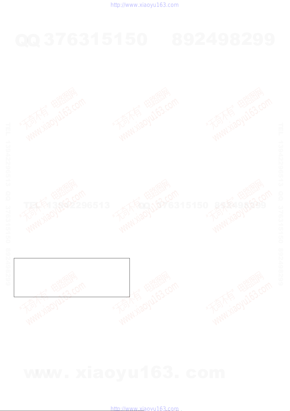
When displaying the version number on the TV screen
When you turn on the system, the version number [VER.X.XX] (X is a
number) may appear on the TV screen.
Although this is not a malfunction and for Sony service use only, normal
system operation will not be possible. Turn off the system, and then turn
on the system again to operate.
HCD-DH3/DH5BT/DH7BT
SAFETY CHECK-OUT
Q
TEL 13942296513 QQ 376315150 892498299
After correcting the original service problem, perform the following
Q
safety check before releasing the set to the customer:
Check the antenna terminals, metal trim, “metallized” knobs, screws,
and all other exposed metal parts for AC leakage.
Check leakage as described below.
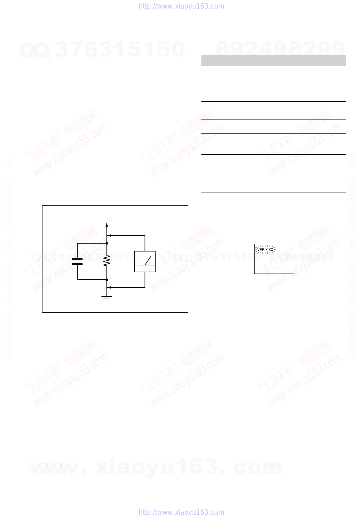
LEAKAGE TEST
The AC leakage from any exposed metal part to earth ground and
from all exposed metal parts to any exposed metal part having a
return to chassis, must not exceed 0.5 mA (500 microamperes.).
Leakage current can be measured by any one of three methods.
1. A commercial leakage tester, such as the Simpson 229 or RCA
2. A battery-operated AC milliammeter. The Data Precision 245
3. Measuring the voltage drop across a resistor by means of a
7
3
WT -540A. Follow the manuf acturers’ instructions to use these
instruments.
digital multimeter is suitable for this job.
VOM or battery-operated A C voltmeter . The “limit” indication
is 0.75 V, so analog meters must have an accurate low-v oltage
scale. The Simpson 250 and Sanwa SH-63Trd are examples
of a passive VOM that is suitable. Nearly all battery operated
digital multimeters that have a 2 V A C range are suitable. (See
Fig. A)
6
To Exposed Metal
Parts on Set
3
1
5
1
5
0
Self-diagnosis Function
(When letters/numbers appear in the display)
When the self-diagnosis function is activated to prevent the system from
malfunctioning, a 5-character service number (e.g. C 13 50) with a
combination of a letter and 4 digits appears on the TV screen and the front
panel display. In this case, check the following table.
First 3 characters of
the service number
C 13 This disc is dirty.
C 31 The disc is not inserted correctly.
E XX
(XX is a number)
SELF DIAGNOSIS FUNCTION
8
9
4
2
9
Cause and corrective action
• Clean the disc with a soft cloth.
• Restart the system, then re-insert the disc
correctly.
To prevent a malfunction, the system has
performed the self-diagnosis function.
• Contact your nearest Sony dealer or local
authorized Sony service facility and give
the 5-character service number.
Example: E 61 10
8
2
9
9
TEL 13942296513 QQ 376315150 892498299
TEL
13942296513
0.15 µF
Fig. A. Using an AC voltmeter to check AC leakage.
1.5 k
Ω
Earth Ground
AC
voltmete
(0.75 V)
Q
Q
3
7
6
3
1
5
1
5
0
8
9
2
4
9
8
2
9
9
w
w
w
.
xia
o
y
u
1
6
3
.
c
o
m
3
HCD-DH3/DH5BT/DH7BT
Ver. 1.2
TABLE OF CONTENTS
7
Q
Q
1. SERVICING NOTES ............................................... 5
2. GENERAL ................................................................... 8
3. DISASSEMBLY
3-1. Disassembly Flow ........................................................... 13
3-2. Steel Cabinet.................................................................... 13
3-3. Front Panel Section ......................................................... 14
3-4. Back Panel Section.......................................................... 14
3-5. Main Chassis Section ...................................................... 15
3-6. DMB15 Board ................................................................. 15
3-7. DVD Mechanism Deck (CDM86-DVBU101) ................ 16
3-8. Belt (MOT) ...................................................................... 16
3-9. Optical Pick-Up Block (KHM-313CAB)........................ 17
TEL 13942296513 QQ 376315150 892498299
4. TEST MODE.............................................................. 18
5. ELECTRICAL CHECKS........................................ 21
6. DIAGRAMS
6-1. Block Diagram – RF SERVO/VIDEO Section – ............ 22
6-2. Block Diagram
– TUNER/USB/BLUETOOTH Section – ....................... 23
6-3. Block Diagram – MAIN Section –.................................. 24
6-4. Block Diagram – KARAOKE/AMP Section – ............... 25
6-5. Block Diagram
– PANEL/POWER SUPPLY Section – ........................... 26
6-6. Printed Wiring Boards – SERVO Section (1/2) –............ 28
6-7. Printed Wiring Board – SERVO Section (2/2) – ............. 29
6-8. Schematic Diagram – SERVO Section (1/4) – ................ 30
TEL
6-9. Schematic Diagram – SERVO Section (2/4) – ................ 31
6-10. Schematic Diagram – SERVO Section (3/4) –................ 32
6-11. Schematic Diagram – SERVO Section (4/4) –................ 33
6-12. Printed Wiring Board – VIDEO Section – ...................... 34
6-13. Schematic Diagram – VIDEO Section – ......................... 35
6-14. Schematic Diagram
– USB Section (1/2) (DH3/DH5BT) – ............................ 36
3
13942296513
6
3
1
5
1
5
0
6-15. Schematic Diagram
– USB Section (2/2) (DH3/DH5BT) – ............................ 37
6-16. Printed Wiring Board
– USB Section (DH3/DH5BT) –..................................... 38
6-17. Printed Wiring Board – MAIN Section – ........................ 39
6-18. Schematic Diagram – MAIN Section (1/2) – .................. 40
6-19. Schematic Diagram – MAIN Section (2/2) – .................. 41
6-20. Printed Wiring Boards
– BLUETOOTH Section (DH5BT/DH7BT) –................ 42
6-21. Schematic Diagram
– BLUETOOTH Section (DH5BT/DH7BT) –................ 43
6-22. Printed Wiring Board – XM Section (DH7BT) –............ 44
6-23. Schematic Diagram – XM Section (DH7BT) – .............. 45
6-24. Printed Wiring Board – AMP Section – .......................... 46
6-25. Schematic Diagram – AMP Section – ............................. 47
6-26. Printed Wiring Boards – INPUT/OUTPUT Section – .... 48
6-27. Schematic Diagram – INPUT/OUTPUT Section –......... 49
6-28. Printed Wiring Board – KARAOKE Section – ............... 50
6-29. Schematic Diagram – KARAOKE Section –.................. 51
6-30. Printed Wiring Boards – PANEL Section –..................... 52
6-31. Schematic Diagram – PANEL Section – ......................... 53
6-32. Printed Wiring Board – POWER SUPPLY Section – ..... 54
6-33. Schematic Diagram – POWER SUPPLY Section – ........ 55
7. EXPLODED VIEWS
7-1. Steel Cabinet Section....................................................... 81
7-2. Front Panel Section ......................................................... 82
7-3. Back Panel Section.......................................................... 83
7-4. DMB15 Board Section .................................................... 84
7-5. MAIN Board Section....................................................... 85
7-6. Power Board Section ....................................................... 86
Q
Q
7-7. DVD Mechanism Deck Section (CDM86-DVBU101) ... 87
8. ELECTRICAL PARTS LIST................................ 88
3
7
8
6
3
9
1
5
2
1
5
4
0
9
8
9
8
2
4
2
9
8
9
2
9
9
TEL 13942296513 QQ 376315150 892498299
9
Refer to SUPPLEMENT-1 for the HP-AMP, JACK, MAIN, POWER
HT and SP boards of printed wiring boards, schematic diagrams
and electrical parts list of DH3: Chinese, Korean, Thai/DH5BT:
Russian, Chinese, Taiwan, Korean, Thai models. When repairing
the set of DH3: Australian, Singapore/DH5BT: Canadian, AEP,
Australian, Singapore/DH7BT models, refer to either of original
service manual/SUPPLEMENT-1 according to the set.
w
w
w
4
.
xia
o
y
u
1
6
3
.
c
o
m
PART
No.
SECTION 1
SERVICING NOTES
HCD-DH3/DH5BT/DH7BT
Ver. 1.2
NOTES ON HANDLING THE OPTICAL PICK-UP
Q
TEL 13942296513 QQ 376315150 892498299
BLOCK OR BASE UNIT
Q
The laser diode in the optical pick-up block may suffer electrostatic
break-down because of the potential difference generated by the
charged electrostatic load, etc. on clothing and the human body.
During repair, pay attention to electrostatic break-down and also
use the procedure in the printed matter which is included in the
repair parts.
The flexible board is easily damaged and should be handled with
care.
NOTES ON LASER DIODE EMISSION CHECK
The laser beam on this model is concentrated so as to be focused on
the disc reflective surface by the objective lens in the optical pickup block. Therefore, when checking the laser diode emission,
observe from more than 30 cm away from the objective lens.
UNLEADED SOLDER
Boards requiring use of unleaded solder are printed with the leadfree mark (LF) indicating the solder contains no lead.
(Caution: Some printed circuit boards may not come printed with
Unleaded solder has the following characteristics.
• Unleaded solder melts at a temperature about 40 °C higher
TEL
• Strong viscosity
• Usable with ordinary solder
7
3
the lead free mark due to their particular size)
: LEAD FREE MARK
than ordinary solder.
Ordinary soldering irons can be used but the iron tip has to be
applied to the solder joint for a slightly longer time.
Soldering irons using a temperature regulator should be set to
about 350 °C.
Caution: The printed pattern (copper foil) may peel away if
13942296513
Unleaded solder is more viscou-s (sticky, less prone to flow)
than ordinary solder so use caution not to let solder bridges
occur such as on IC pins, etc.
It is best to use only unleaded solder but unleaded solder may
also be added to ordinary solder.
6
the heated tip is applied for too long, so be careful!
3
1
5
1
5
0
Q
Q
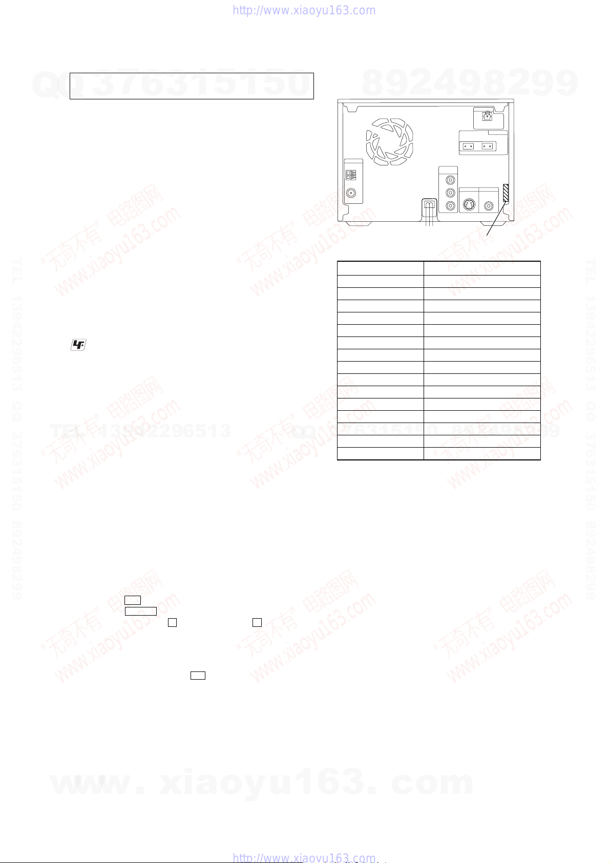
MODEL IDENTIFICATION
– Back Panel –
DH3: Singapore 2-892-818-0[]
DH3: Australian 2-892-818-1[]
DH3: Korean 2-892-818-3[]
DH3: Thai 2-892-818-6[]
DH3: Chinese 2-892-818-7[]
DH7BT 2-892-844-0[]
DH5BT: Canadian 2-892-844-1[]
DH5BT: AEP 2-892-844-2[]
DH5BT: Singapore 2-892-844-3[]
DH5BT: Australian 2-892-844-4[]
DH5BT: Kor ean 2-892-844-6[]
DH5BT: Taiwan 2-892-844-8[]
DH5BT: Thai 2-892-844-9[]
7
3
DH5BT: Russian 2-892-845-0[]
DH5BT: Chinese 2-892-845-1[]
4
2
9
8
MODEL PART No.
0
5
1
5
1
3
6
9
8
9
8
2
4
2
9
8
9
2
9
9
TEL 13942296513 QQ 376315150 892498299
9
RELEASING THE DISC ANTITHEFT
The disc lock function for the antitheft of an demonstration disc in
the store is equipped.
Releasing Procedure :
1. Press the
2. Press the DVD N button to select the “DVD”.
3. While pressing the x button, press the Z button until
“UNLOCKED” displayed on the fluorescent indicator tube
(around 5 seconds).
Note: When “LOCKED” is displayed, the disc lock is not released by
turning power on/off with the I/1 button.
NOTES ON REPLACEMENT OF THE DMB15 BOARD
New part of EEPROM (IC103) on the DMB15 board cannot be
used. Therefore, if the mounted DMB15 board is replaced, exchange
new EEPROM with that used before the replacement.
w
w
I/1 button to turn on the system.
w
.
xia
o
y
u
1
6
3
.
c
o
m
5
HCD-DH3/DH5BT/DH7BT
7
Q
Q
TEL 13942296513 QQ 376315150 892498299
TEL
3
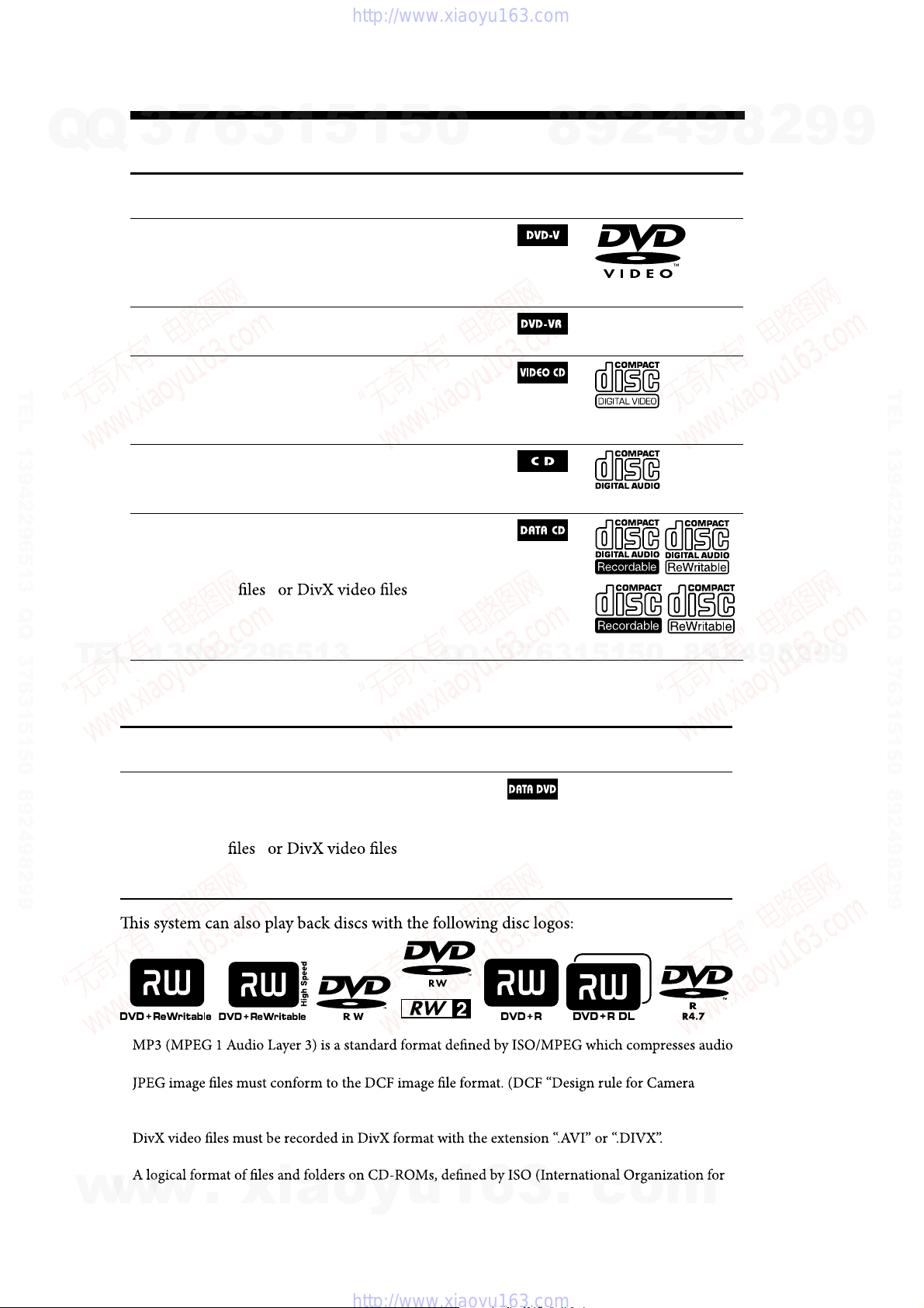
Playable discs
Type Characteristics
DVD VIDEO
VR mode
VIDEO CD
CD
DAT A CD
13942296513
6
in DVD VIDEO format
*
in VR (Video Rec ording) mode
*
*
in DATA CD format, containing
MP3 audio tracks
conforming to ISO 9660
1 or Level 2, or Joliet (expansion
format).
1
5
1
3
• DVD VIDEO
• DVD-R*/-RW*/+R/+RW
also in video mode
• DVD-R/-RW
• VIDEO CD
• Super VCD*
• CD-ROM*/-R*/-RW*
in VIDEO CD or Super VCD format
• AUDIO CD*
• CD-R*/-RW*
in AUDIO CD format
• CD-ROM/-R/-RW
2) 3)
5
0
1)
, JPEG image
, and
4)
Level
Q
Q
Icon used in
this manual
7
3
8
6
3
9
1
5
2
1
5
4
Logo
0
9
8
9
8
2
4
2
9
8
9
2
9
9
TEL 13942296513 QQ 376315150 892498299
9
Type Characteristics
w
w
DA T A DVD
1)
data. MP3 audio tracks must be in MPEG 1 Audio Layer 3 format.
2)
File Sy stem ”: Image standards for digital cameras regulated by Ja pan Elec tronics and Information
Technology Industries Association (JEI T A)).
3)
(Except US and Canadian models)
4)
Standardization).
w
• DVD-ROM/-R/-RW/+R/+RW
in DATA DVD format containing
MP3 audio tracks
2) 3)
conforming to UDF (Universal Disk
Format).
.
xia
1)
, JPEG image
o
y
, and
u
1
6
Icon used in
this manual
3
.
c
Logo
o
m
“DVD+RW,” “DVD-RW,” “DVD+R,” “DVD VIDEO,” and the “CD” logos are trademarks.
6
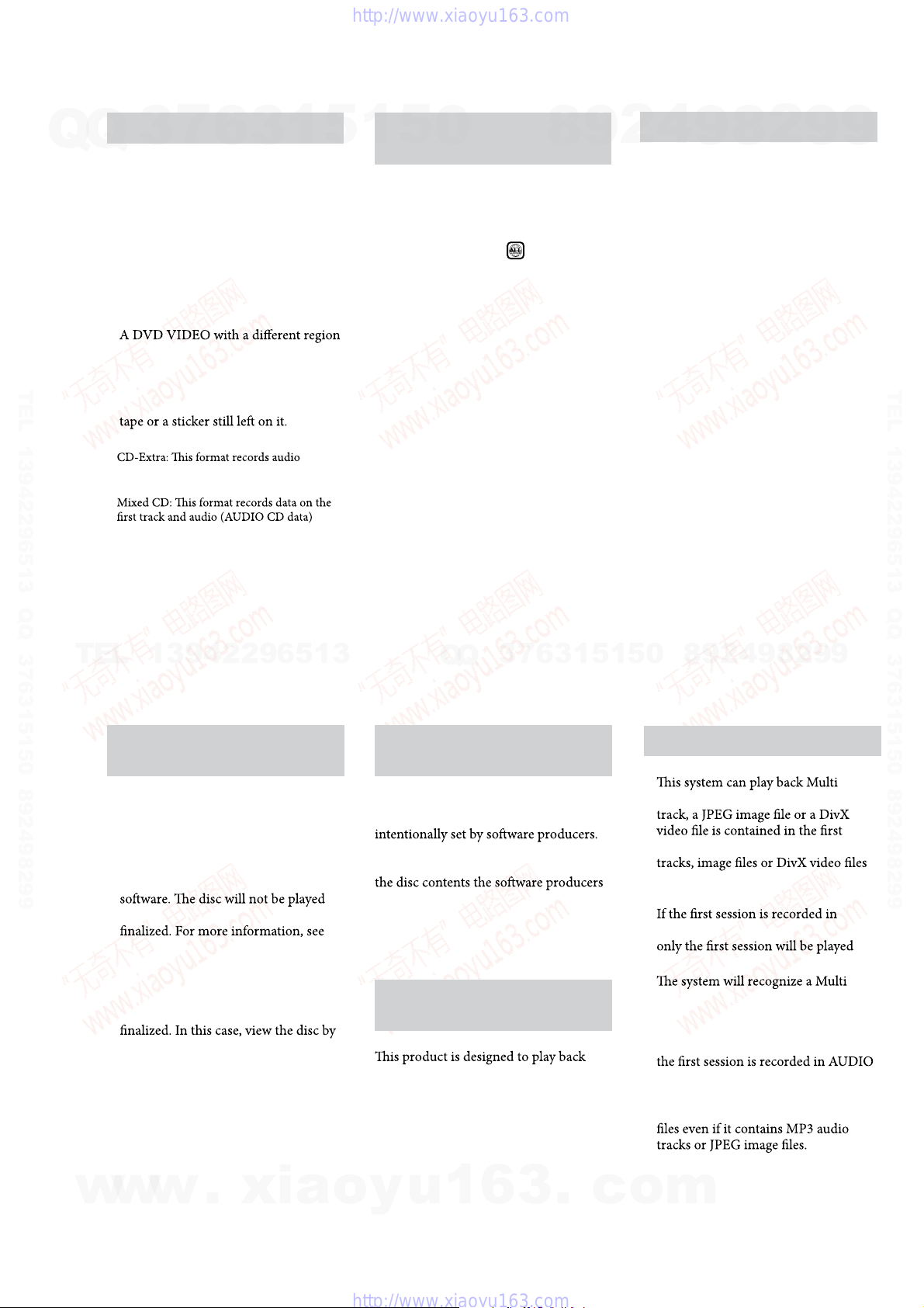
Discs that cannot be played
CD-ROMs recorded in PHOTO CD
format
DATA CDs recorded in MP3 PRO
format
Data part of CD-Extras
1)
Data part of Mixed CDs
2)
Super Audio CDs
DVD Audio discs
DVD-RAMs
code.
A disc that has a non-standard shape
(e.g., heart, square, star).
A disc that has the adhesive cellophane
1)
(AUDIO CD data) on the tracks in session 1
and data on the tracks in session 2.
2)
on the second and subsequent tracks of a
session.
Region code of DVD VIDEOs you
can play back on this system
Your system has a region code printed
on the back of th e unit and will only
play back DVD VIDEOs labele d with
identical region code.
DVD VIDEOs label ed
will also be
played back on this system.
If you try to play back any other region
code DVD VIDEO, the message
“Playback prohibited by area limitations.”
will appear on the TV screen. Dependi ng
on the DVD VIDEO, no region code
indi cat ion may be labeled even though
playing the DVD VIDEO is prohibited by
area restrictions.
Note on DualDiscs
ADualDisc is a two sided disc product
which mates DVD recorded material on
one side with digital audio material on
the other side. However, since the audio
material side does not conform to the
Compact Disc (CD) standard, playback
on this product is not guaranteed.
•
•
•
•
•
•
•
•
•
•
HCD-DH3/DH5BT/DH7BT
7
Q
Q
TEL 13942296513 QQ 376315150 892498299
3
6
3
1
5
1
5
0
8
9
2
4
9
8
2
9
9
TEL 13942296513 QQ 376315150 892498299
TEL
w
13942296513
Notes on CD-R/-RW and
DVD-R/-RW/+R/+RW
•
In some cases, CD-Rs/-RWs and
DVD-Rs/-RWs/+Rs/+R Ws c a nnot be
played back on this system due to the
recording quality or physic al condition
of the disc, or the characteristics of
the recording device a nd authoring
back if it has not been correct ly
the operation instructions for the
recording device.
Note that some playbac k functions
•
may not work with some DVD+Rs/
+RWs, even if they have been correctly
norma l pl ayba ck.
•
A disc created in Packet Write format
cannot be played back.
w
w
.
Q
Q
Note on playback operations of
DVD VIDEOs and VIDEO CDs
Some playback operations of DVD
VIDEOs and VIDEO CDs may be
Since this sy stem play back DVD
VIDEOs and VIDEO CDs according to
xia
designed, some playback f eatures may
not be available. Also, refer to the
instructions supplied with the DVD
VIDEOs or VIDEO CDs.
Music discs encoded with
copyright protection technologies
discs that conform to the Compact Disc
(CD) standar d. Recently, various music
discs encoded with copyright protection
technologies a re marketed by some
record companies. Please be aware that
among those discs, there are some that
do not conform to the CD standard and
may no t be playable by this product.
o
y
u
1
3
6
9
8
0
5
1
5
1
3
6
7
Notes on Multi Session disc
•
Session discs when an MP3 audio
session. Any subsequent MP3 audio
3
.
c
recorded in later sessions can also be
played back.
•
AUDIO CD or VIDEO CD format,
back.
•
Session disc as an A UDIO CD if there
is a session recorded in AUDIO CD
format on the disc. Howev er, the
sys tem will only play back the disc if
CD format.
•
With DATA CD or DAT A DVD , the
system will only play back DivX video
(Except US and Canadian models)
o
m
2
4
9
8
2
9
9
7
HCD-DH3/DH5BT/DH7BT
SECTION 2
GENERAL
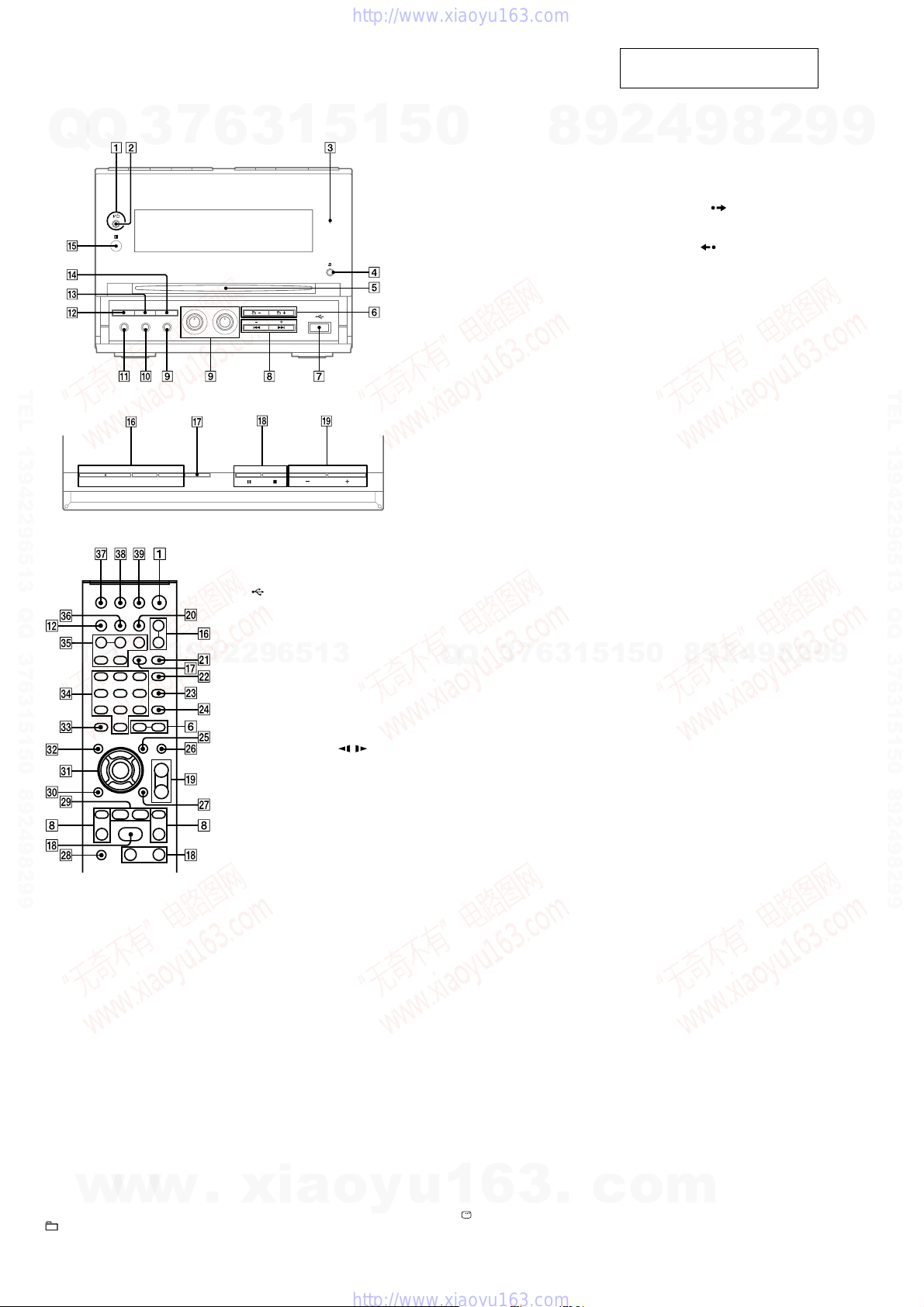
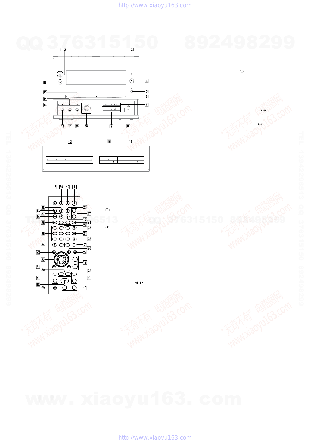
– HCD-DH3 –
Front panel
Q
Q
3
6
7
TEL 13942296513 QQ 376315150 892498299
Top panel
Remote control (RM-SCD31)
TEL
1
Unit: ?/1 (on/standby)
Remote: TV
Press to turn on the system.
Press to turn on the TV.
2
STANDBY indicator
Lights up when the system is turned off.
3
USB MEMORY indicator
Lights up when an optional USB device
(Digital music player or USB storage
media) is connected.
4
Z (eject)
Press to eject the disc.
5
Disc slot
w
6
+/−
Press to select an album.
13942296513
1)
?/1
(on/standby)
w
w
.
1
5
1
3
7
(USB) port
Connect to an optional USB device
(Digital music player or USB storage media).
8
PRESET +/−
Press to select the preset station.
./> (go backward/
forward)
Press to select a track or file.
Remote: TV CH +/−
Press to change the TV channels.
Remote: SLOW /
Press to watch the slow-motion play.
Remote: TUNING +/−
Press to tune in the desired station.
m/M (rewind/fast forward)
Press to find a point in a track or file.
9
ECHO LEVEL
Press to adjust the microphone echo.
MIC LEVEL
Press to adjust the microphone volume.
MIC jack
Connect to a microphone.
q;
AUDIO IN jack
Connect to an optional audio
component.
qa
PHONES jack
Connect the headphones.
qs
DISPLAY
Press to display the disc information or
clock in the front panel display.
qd
PROGRESSIVE
Press to change the output video format
(Interlace or Progressive format).
xia
qf
DSGX
Press to reinforce the bass.
o
5
1)
y
u
0
qg
IR Receptor
qh
Unit: DVD N (play)
Press to select the DVD function.
Press to start playback of a disc.
Unit: USB N (play)
Press to select the USB function.
Press to start playback an optional USB
device (Digital music player or USB
storage media).
Unit: TUNER/BAND
Press to select the TUNER function.
Press to switch among FM and AM band.
Unit: AUDIO IN
Press to select the AUDIO IN function.
FUNCTION +/−
Press to select the function.
qj
REPEAT/FM MODE
Press to listen to a disc, a single track or
file repeatedly.
Press to select FM reception mode
(monaural or stereo).
qk
x (stop)
X (pause)
Press to stop or pause playback.
Remote: H2) (play)
Press to start playback.
ql
VOLUME +/−
Q
Q
Press to adjust the volume.
TV VOL +/−
Press to adjust the TV volume.
w;
DIMMER
Press to adjust the brightness of the
display.
wa
PICTURE NAVI
Press to select the VIEWER format for
searching the chapters, titles and tracks.
Press to display the thumbnail pictures.
ws
AUDIO
Press to display the current audio signal
on the TV screen.
wd
SUBTITLE
Press to switch the language of the
subtitle (DVD VIDEO).
wf
ANGLE
Press to change the angle (DVD VIDEO
with multi-angles only).
wg
DVD/USB/TUNER MENU
Press to display the MENU items on the
TV screen.
Press to preset the radio station.
Press to select the play mode when using
an optional USB device.
wh
EQ
Press to select the sound effect.
1
wj
Press to display the Control Menu on the
TV screen.
3
6
DISPLAY
7
1)2)
3
8
2)
6
3
.
9
1
This section is extracted from
instruction manual.
4
1
5
c
2
5
o
0
9
wk
1)
TV
Press to operate the TV functions.
wl
ADVANCE
Press to advance the current scene during
playback.
REPLAY
Press to replay the previous scene during
playback.
c STEP/ STEP C
Press to play one frame at a time when
playback is paused.
e;
O RETURN
Press to return to the previous menu on
the TV screen.
ea
V/v/B/b
Press to select the MENU items.
ENTER
Press to enter the settings.
es
DVD TOP MENU
Press to display the DVD title on the TV
screen.
ed
CLEAR
Press to delete a pre-programmed track
or file.
1)
-/--
Press to enter a single digit or double
digit number.
ef
Numeric buttons
Press to select a track or file.
Press to enter a password or passcode.
1)
10/0
Press to enter a double digit number.
eg
KEY CONTROL 2/#
Press to change the key to suit your vocal
range.
SCORE
Press to select the difficulty level for
scoring mode.
KARAOKE MODE
Press to select the Karaoke mode.
KARAOKE PON
Press to activate the KARAOKE PON
function.
eh
TIME/TEXT
Press to change the information in the
front panel display.
ej
TV/VIDEO
Press to switch the input sources.
SLEEP
Press to set the Sleep Timer.
ek
TIMER MENU
Press to set the clock and the timers.
el
THEATRE SYNC
Press to activate the THEATRE SYNC
function.
1)
This button is used to operate a Sony TV.
For details, see “Operating a Sony TV”.
2)
The numeric button 5, TV VOL +,
VOLUME + ql and H qk buttons have a
m
tactile dot. Use the tactile dot as a reference
when operating the system.
8
9
2
1)
8
2)
4
2
9
8
9
2
9
9
TEL 13942296513 QQ 376315150 892498299
9
8
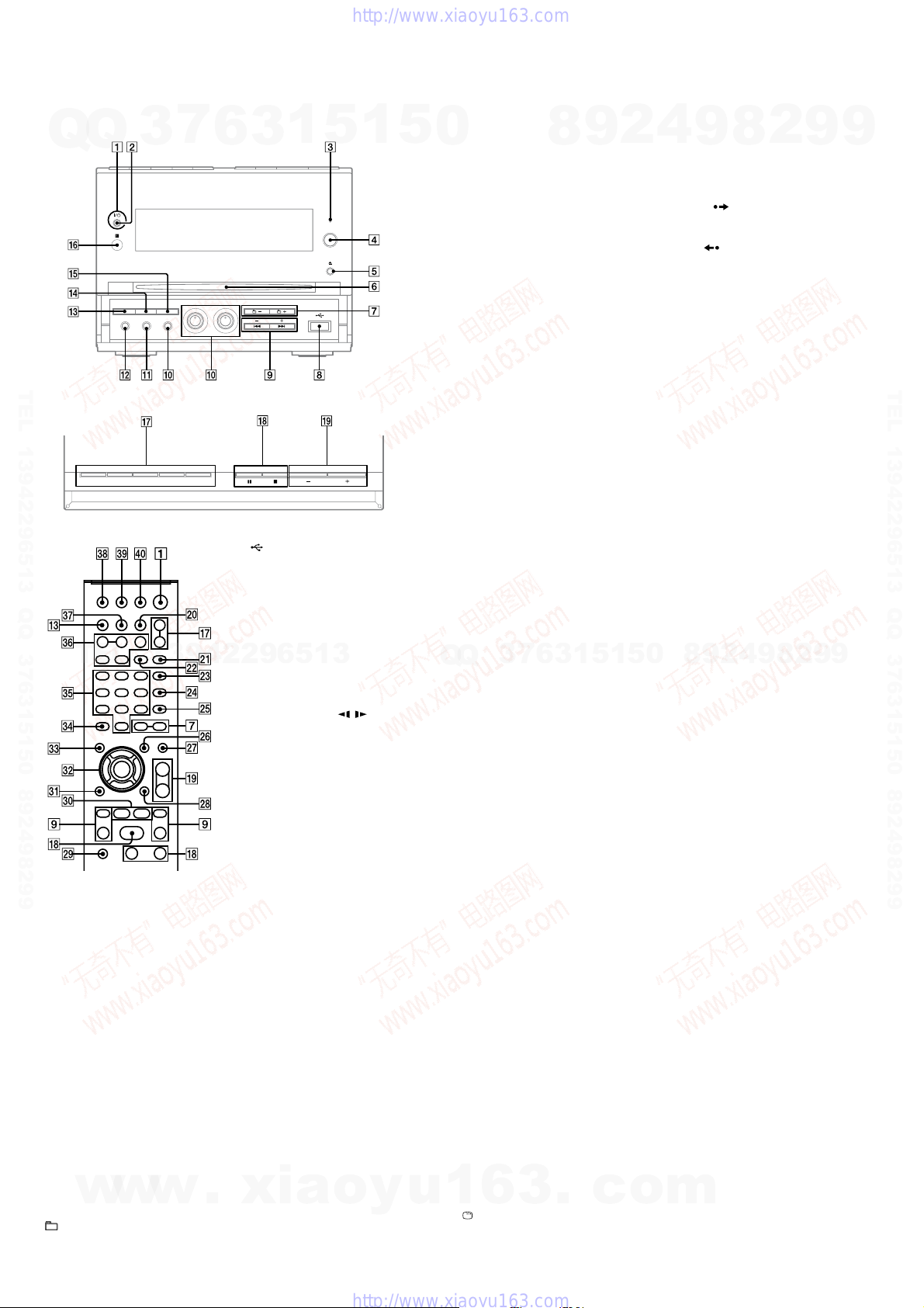
– HCD-DH5BT: Canadian model –
Q
Front panel
Q
3
7
6
3
1
5
1
5
0
TEL 13942296513 QQ 376315150 892498299
Top panel
Remote control (RM-SCD32)
7
+/−
Press to select an album.
TEL
w
13942296513
1
Unit: ?/1 (on/standby)
Remote: TV
Press to turn on the system.
Press to turn on the TV.
2
STANDBY indicator
Lights up when the system is turned off.
3
BLUETOOTH indicator
Lights up when the Bluetooth function
is active.
4
BLUETOOTH OPR
Press to make a connection,
disconnection, or pairing with a
Bluetooth device.
5
Z (eject)
w
w
Press to eject the disc.
6
Disc slot
?/1
1)
(on/standby)
.
xia
8
(USB) port
Connect to an optional USB device
(Digital music player or USB storage
media).
9
PRESET +/−
Press to select the preset station.
./> (go backward/
forward)
Press to select a track or file.
Remote: TV CH +/−
Press to change the TV channels.
Remote: SLOW /
Press to watch the slow-motion play.
Remote: TUNING +/−
Press to tune in the desired station.
m/M (rewind/fast forward)
Press to find a point in a track or file.
q;
MIC LEVEL
Press to adjust the microphone volume.
MIC jack
Connect to a microphone.
qa
AUDIO IN jack
Connect to an optional audio
component.
qs
PHONES jack
Connect the headphones.
qd
DISPLAY
Press to display the disc information or
clock in the front panel display.
qf
o
y
PROGRESSIVE
Press to change the output video format
(Interlace or Progressive format).
u
Q
Q
1)
1
qg
DSGX
Press to reinforce the bass.
qh
IR Receptor
qj
Unit: DVD N (play)
Press to select the DVD function.
Press to start playback of a disc.
Unit: USB N (play)
Press to select the USB function.
Press to start playback an optional USB
device (Digital music player or USB
storage media).
Unit: BLUETOOTH N
Press to select the Bluetooth function.
Press to start playback of the music on
the Bluetooth device (Bluetooth mobile
phone, etc.).
Unit: TUNER/BAND
Press to select the TUNER function.
Press to switch among FM and AM band.
Unit: AUDIO IN
Press to select the AUDIO IN function.
FUNCTION +/−
Press to select the function.
qk
x (stop)
X (pause)
Press to stop or pause playback.
Remote: H2) (play)
Press to start playback.
ql
7
3
VOLUME +/−
Press to adjust the volume.
TV VOL +/−
Press to adjust the TV volume.
w;
TIMER MENU
Press to set the clock and the timers.
wa
PICTURE NAVI
Press to select the VIEWER format for
searching the chapters, titles and tracks.
Press to display the thumbnail pictures.
ws
REPEAT
Press to listen to a disc, a single track or
file repeatedly.
FM MODE
Press to select FM reception mode
(monaural or stereo).
wd
AUDIO
Press to display the current audio signal
on the TV screen.
wf
SUBTITLE
Press to switch the language of the
subtitle (DVD VIDEO).
wg
ANGLE
Press to change the angle (DVD VIDEO
with multi-angles only).
wh
DVD/USB MENU
6
3
Press to display the MENU items on the
TV screen.
Press to select the play mode when using
an optional USB device.
8
6
3
.
9
1
1
5
2)
1)2)
c
HCD-DH3/DH5BT/DH7BT
2
5
o
4
0
m
wj
9
EQ
Press to select the sound effect.
wk
Press to display the Control Menu on the
TV screen.
wl
TV
Press to operate the TV functions.
e;
ADVANCE
Press to advance the current scene during
playback.
REPLAY
Press to replay the previous scene during
playback.
c STEP/ STEP C
Press to play one frame at a time when
playback is paused.
ea
O RETURN
Press to return to the previous menu on
the TV screen.
es
V/v/B/b
Press to select the MENU items.
ENTER
Press to enter the settings.
ed
DVD TOP MENU
Press to display the DVD title on the TV
screen.
2
9
8
ef
CLEAR
Press to delete a pre-programmed track
or file.
Press to erase the pairing registration
information of the Bluetooth device.
-/--
Press to enter a single digit or double
digit number.
eg
Numeric buttons
Press to select a track or file.
Press to enter a password or passcode.
10/0
Press to enter a double digit number.
eh
TUNER MEMORY
Press to preset the radio station.
ej
DIMMER
Press to adjust the brightness of the
display.
ek
TIME/TEXT
Press to change the information in the
front panel display.
el
TV/VIDEO
Press to switch the input sources.
SLEEP
Press to set the Sleep Timer.
r;
THEATRE SYNC
Press to activate the THEATRE SYNC
function.
1)
This button is used to operate a Sony TV.
2)
The numeric button 5, TV VOL +,
2
8
DISPLAY
1)
4
1)
1)
For details, see “Operating a Sony TV”.
VOLUME +
tactile dot. Use the tactile dot as a reference
when operating the system.
9
9
2
8
9
2)
1)
ql
and H qk buttons have a
9
TEL 13942296513 QQ 376315150 892498299
9
9
HCD-DH3/DH5BT/DH7BT
Ver. 1.1
– HCD-DH5BT: AEP, Russian, Australian, Singapore, Taiwan, Korean and Thai models –
Front panel
Q
Q
3
7
6
3
1
5
1
5
TEL 13942296513 QQ 376315150 892498299
Top panel
Remote control (RM-SCD31)
TEL
1
Unit: ?/1 (on/standby)
Remote: TV
Press to turn on the system.
Press to turn on the TV.
2
STANDBY indicator
Lights up when the system is turned off.
3
BLUETOOTH indicator
Lights up when the Bluetooth function is active.
4
BLUETOOTH OPR
Press to make a connection, disconnection,
or pairing with a Bluetooth device.
5
Z (eject)
Press to eject the disc.
6
Disc slot
w
7
+/−
Press to select an album.
13942296513
1)
?/1
(on/standby)
w
w
.
8
(USB) port
Connect to an optional USB device
(Digital music player or USB storage
media).
9
PRESET +/−
Press to select the preset station.
./> (go backward/
forward)
Press to select a track or file.
Remote: TV CH +/−
Press to change the TV channels.
Remote: SLOW /
Press to watch the slow-motion play.
Remote: TUNING +/−
Press to tune in the desired station.
m/M (rewind/fast forward)
Press to find a point in a track or file.
q;
ECHO LEVEL
Press to adjust the microphone echo.
MIC LEVEL
Press to adjust the microphone volume.
MIC jack
Connect to a microphone.
qa
AUDIO IN jack
Connect to an optional audio
component.
qs
PHONES jack
Connect the headphones.
qd
DISPLAY
Press to display the disc information or
clock in the front panel display.
qf
PROGRESSIVE
Press to change the output video format
(Interlace or Progressive format).
qg
DSGX
Press to reinforce the bass.
xia
qh
IR Receptor
2)
o
1)
y
u
qj
0
Unit: DVD N (play)
Press to select the DVD function.
Press to start playback of a disc.
Unit: USB N (play)
Press to select the USB function.
Press to start playback an optional USB
device (Digital music player or USB
storage media).
Unit: BLUETOOTH N
Press to select the Bluetooth function.
Press to start playback of the music on
the Bluetooth device (Bluetooth mobile
phone, etc.).
Unit: TUNER/BAND
Press to select the TUNER function.
Press to switch among FM and AM band.
Unit: AUDIO IN
Press to select the AUDIO IN function.
FUNCTION +/−
Press to select the function.
qk
x (stop)
X (pause)
Press to stop or pause playback.
Remote: H3) (play)
Press to start playback.
ql
VOLUME +/−
Press to adjust the volume.
TV VOL +/−
Press to adjust the TV volume.
w;
DIMMER
3
Press to adjust the brightness of the display.
Q
Q
wa
PICTURE NAVI
Press to select the VIEWER format for
searching the chapters, titles and tracks.
Press to display the thumbnail pictures.
ws
REPEAT/FM MODE
Press to listen to a disc, a single track or
file repeatedly.
Press to select FM reception mode
(monaural or stereo).
wd
AUDIO
Press to display the current audio signal
on the TV screen.
wf
SUBTITLE
Press to switch the language of the
subtitle (DVD VIDEO).
wg
ANGLE
Press to change the angle (DVD VIDEO
with multi-angles only).
wh
DVD/USB/TUNER MENU
Press to display the MENU items on the
TV screen.
Press to preset the radio station.
Press to select the play mode when using
an optional USB device.
wj
EQ
Press to select the sound effect.
1
6
wk
DISPLAY
Press to display the Control Menu on the
TV screen.
3)
1)3)
6
7
3
8
3
.
9
1
1
5
c
wl
4
2
1)
TV
Press to operate the TV functions.
e;
ADVANCE
Press to advance the current scene during
playback.
REPLAY
Press to replay the previous scene during
playback.
c STEP/ STEP C
Press to play one frame at a time when
playback is paused.
ea
O RETURN
Press to return to the previous menu on
the TV screen.
es
V/v/B/b
Press to select the MENU items.
ENTER
Press to enter the settings.
ed
DVD TOP MENU
Press to display the DVD title on the TV
screen.
ef
CLEAR
Press to delete a pre-programmed track
or file.
Press to erase the pairing registration
information of the Bluetooth device.
1)
-/--
Press to enter a single digit or double
digit number.
8
0
5
eg
Numeric buttons
Press to select a track or file.
Press to enter a password or passcode.
1)
10/0
Press to enter a double digit number.
eh
KEY CONTROL 2/#
Press to change the key to suit your vocal
range.
SCORE
Press to select the difficulty level for
scoring mode.
KARAOKE MODE
Press to select the Karaoke mode.
KARAOKE PON
Press to activate the KARAOKE PON
function.
ej
TIME/TEXT
Press to change the information in the
front panel display.
ek
TV/VIDEO
Press to switch the input sources.
SLEEP
Press to set the Sleep Timer.
el
TIMER MENU
Press to set the clock and the timers.
r;
THEATRE SYNC
Press to activate the THEATRE SYNC
function.
1)
This button is used to operate a Sony TV.
For details, see “Operating a Sony TV”.
2)
Except for European and Russian models.
o
m
3)
The numeric button 5, TV VOL +,
VOLUME +
tactile dot. Use the tactile dot as a reference
when operating the system.
8
9
4
2
9
3)
1)
ql
and H qk buttons have a
2
9
8
9
2
9
9
TEL 13942296513 QQ 376315150 892498299
9
10
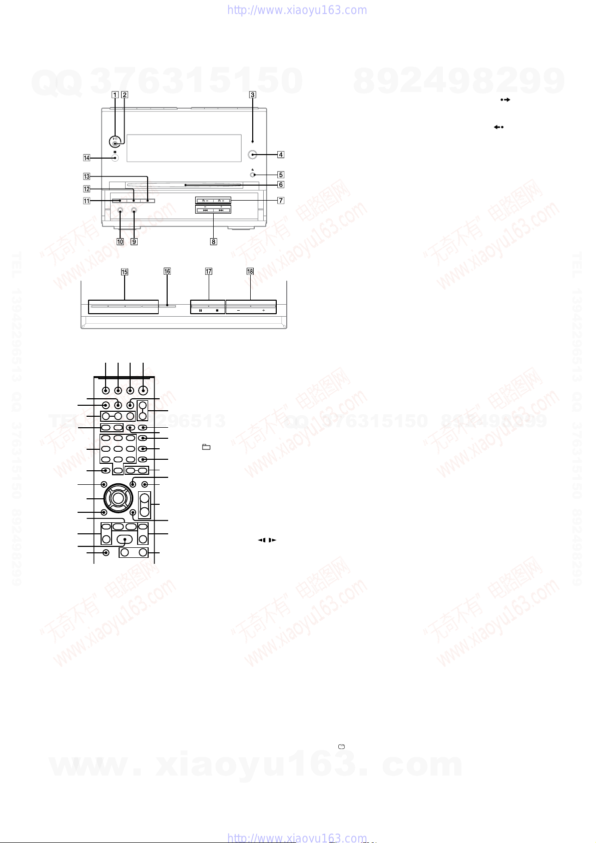
– HCD-DH7BT –
Q
Front panel
Q
3
7
6
3
1
5
1
5
0
TEL 13942296513 QQ 376315150 892498299
Top panel
Remote control (RM-SCD30)
ej ek el 1
eh
qa
TEL
w
eg
13942296513
ef
ed
es
ea
e;
wl
wk
8
qj
wj
1
Unit: ?/1 (on/standby)
Remote: TV
Press to turn on the system.
Press to turn on the TV.
2
STANDBY indicator
Lights up when the system is turned off.
3
BLUETOOTH indicator
Lights up when the Bluetooth function
is active.
4
BLUETOOTH OPR
Press to make a connection,
disconnection, or pairing with a
Bluetooth device.
w
5
Z (eject)
Press to eject the disc.
?/1
w
1)
ql
qg
w;
qh
wa
ws
wd
7
wf
wg
qk
wh
8
qj
(on/standby)
.
xia
6
Disc slot
7
+/−
Press to select an album.
8
PRESET +/−
Press to select the preset station.
./> (go backward/
forward)
Press to select a track or file.
Remote: TV CH +/−
Press to change the TV channels.
Remote: SLOW /
Press to watch the slow-motion play.
Remote: TUNING +/−
Press to tune in the desired station.
m/M (rewind/fast forward)
Press to find a point in a track or file.
9
AUDIO IN jack
Connect to an optional audio
component.
q;
PHONES jack
Connect the headphones.
qa
DISPLAY
Press to display the disc information or
clock in the front panel display.
qs
PROGRESSIVE
Press to change the output video format
(Interlace or Progressive format).
qd
DSGX
Press to reinforce the bass.
o
y
u
qf
IR Receptor
Q
Q
1)
1
qg
Unit: DVD N (play)
Press to select the DVD function.
Press to start playback of a disc.
Unit: BLUETOOTH N
Press to select the Bluetooth function.
Press to start playback of the music on
the Bluetooth device (Bluetooth mobile
phone, etc.).
Unit: TUNER/BAND
Press to select the TUNER function.
Press to switch among FM, AM, XM and
SIRIUS band.
Unit: AUDIO IN
Press to select the AUDIO IN function.
FUNCTION +/−
Press to select the function.
qh
Unit: REPEAT/FM MODE
Remote: FM MODE
Remote: REPEAT
Press to select FM reception mode
(monaural or stereo).
Press to listen to a disc, a single track or
file repeatedly.
qj
x (stop)
X (pause)
Press to stop or pause playback.
Remote: H2) (play)
Press to start playback.
qk
VOLUME +/−
Press to adjust the volume.
TV VOL +/−
7
3
Press to adjust the TV volume.
ql
DIMMER
Press to adjust the brightness of the
display.
w;
PICTURE NAVI
Press to select the VIEWER format for
searching the chapters, titles and tracks.
Press to display the thumbnail pictures.
wa
AUDIO
Press to display the current audio signal
on the TV screen.
ws
SUBTITLE
Press to switch the language of the
subtitle (DVD VIDEO).
wd
ANGLE
Press to change the angle (DVD VIDEO
with multi-angles only).
wf
DVD/TUNER MENU
Press to display the MENU items on the
TV screen.
Press to preset the radio station.
wg
EQ
Press to select the sound effect.
wh
Press to display the Control Menu on the
TV screen.
6
3
wj
TV
Press to operate the TV functions.
8
1
3
6
DISPLAY
.
1)
9
2)
1)2)
5
c
HCD-DH3/DH5BT/DH7BT
2
1
0
5
o
4
8
m
wk
9
ADVANCE
Press to advance the current scene during
playback.
REPLAY
Press to replay the previous scene during
playback.
c STEP/ STEP C
Press to play one frame at a time when
playback is paused.
wl
O RETURN
Press to return to the previous menu on
the TV screen.
e;
V/v/B/b/
Press to select the MENU items.
ENTER
Press to enter the settings.
ea
DVD TOP MENU
Press to display the DVD title on the TV
screen.
es
CLEAR
Press to delete a pre-programmed track
or file.
Press to delete a number entry.
Press to erase the pairing registration
information of the Bluetooth device.
-/--
Press to enter a single digit or double
digit number.
ed
Numeric buttons
Press to select a track, file or satellite
2
9
channel.
Press to enter a Parental Lock password.
Press to enter a Bluetooth passcode.
10/0
Press to enter a double digit number.
ef
XM
Press to select XM band.
SIRIUS
Press to select SIRIUS band.
eg
CATEGORY +/−
Press to select a satellite radio category.
CATEGORY MODE
Press to select the tuning mode for XM
or SIRIUS band.
eh
TIME/TEXT
Press to change the information in the
front panel display.
ej
TV/VIDEO
Press to switch the input sources.
SLEEP
Press to set the Sleep Timer.
ek
TIMER MENU
Press to set the clock and the timers.
el
THEATRE SYNC
Press to activate the THEATRE SYNC
function.
1)
This button is used to operate a Sony TV.
For details, see “Operating a Sony TV”.
2)
The numeric button 5, TV VOL +,
VOLUME +
tactile dot. Use the tactile dot as a reference
when operating the system.
8
1)
4
2)
2
2
8
9
1)
qk
and H qj buttons have a
9
2)
9
9
TEL 13942296513 QQ 376315150 892498299
9
11
HCD-DH3/DH5BT/DH7BT
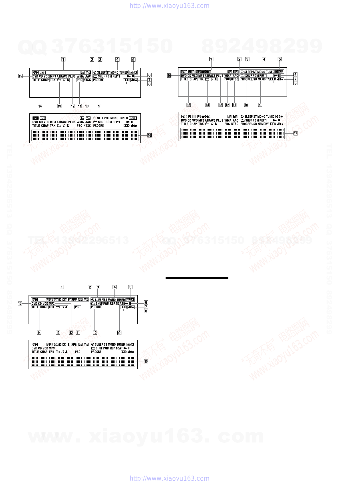
– HCD-DH3 –
7
Display
Q
Q
TEL 13942296513 QQ 376315150 892498299
1
Indicates the selected function.
Indicates the selected play mode.
2
Lights up when timer is set.
3
Lights up when a station is tuned in.
4
5
Lights up when DSGX is turned on.
6
Indicates the Playback status.
7
Lights up when DTS is selected.
8
Lights up when Dolby Digital is
selected.
Lights up when “P AUTO” or
9
“P VIDEO” is selected.
3
6
1
5
3
q;
Lights up when the output video
signal is NTSC.
Lights up when playing VIDEO CD
qa
with PBC.
Indicates the type of audio format.
qs
Indicates the track/album
qd
information.
Lights up when chapter or title
qf
number is displayed.
Indicates the type of disc being played
qg
back.
Displays the text information.
qh
1
5
– HCD-DH5BT –
0
Display
1 Indicates the selected function.
2 Indicates the selected play mode.
3 Lights up when timer is set.
4 Lights up when a station is tuned in.
5 Lights up when DSGX is turned on.
6 Indicates the Playback status.
7 Lights up when DTS is selected.
8 Lights up when Dolby Digital is
selected.
9 Lights up when an optional USB
device is connected.
q; Lights up when “P AUTO” or
“P VIDEO” is selected.
8
9
4
2
qa Lights up when the output video
signal is NTSC.
(Except Canadian model)
qs Lights up when playing VIDEO CD
with PBC.
qd Indicates the type of audio format.
qf Indicates the track/album
information.
qg Lights up when chapter or title
number is displayed.
qh Indicates the type of disc being played
back.
qj Displays the text information.
9
8
2
9
9
TEL 13942296513 QQ 376315150 892498299
TEL
– HCD-DH7BT –
Display
1 Indicates the selected function.
2 Indicates the selected play mode.
3 Lights up when timer is set.
4 Lights up when a station is tuned in.
5 Lights up when DSGX is turned on.
6 Indicates the Playback status.
7 Lights up when DTS is selected.
8 Lights up when Dolby Digital is
selected.
9 Lights up when CATEGORY MODE
is selected.
w
13942296513
w
w
.
q; Lights up when “P AUTO” or
“P VIDEO” is selected.
qa Lights up when playing VIDEO CD
with PBC.
qs Lights up when playing an MP3 audio
track.
qd Indicates the track/album
information.
qf Lights up when chapter or title
number is displayed.
qg Indicates the type of disc being played
back.
qh Displays the text information.
xia
o
y
3
6
7
3
Q
Q
Setting the clock
Use buttons on the remote to set the
clock.
1
Press ?/1 to turn on the
system.
2
Press TIMER MENU.
The hour indication flashes in the
display.
If “PLAY SET?” flashes in the
display, press V or v repeatedly
to select “CLOCK SET?,” then press
ENTER.
3
Press V or v repeatedly to set
the hour.
4
Press ENTER.
The minute indication flashes in the
display.
5
Press V or v repeatedly to set
the minutes.
6
Press ENTER.
The clock starts functioning.
Note
The clock settings are canceled when you
disconnect the power cord or if a power failure
occurs.
To display the clock when the system
is off
u
1
6
3
Press DISPLAY.
The clock is displayed for about
8 seconds.
.
1
1
5
c
0
5
o
9
8
m
2
4
9
8
2
9
9
12
s
Q
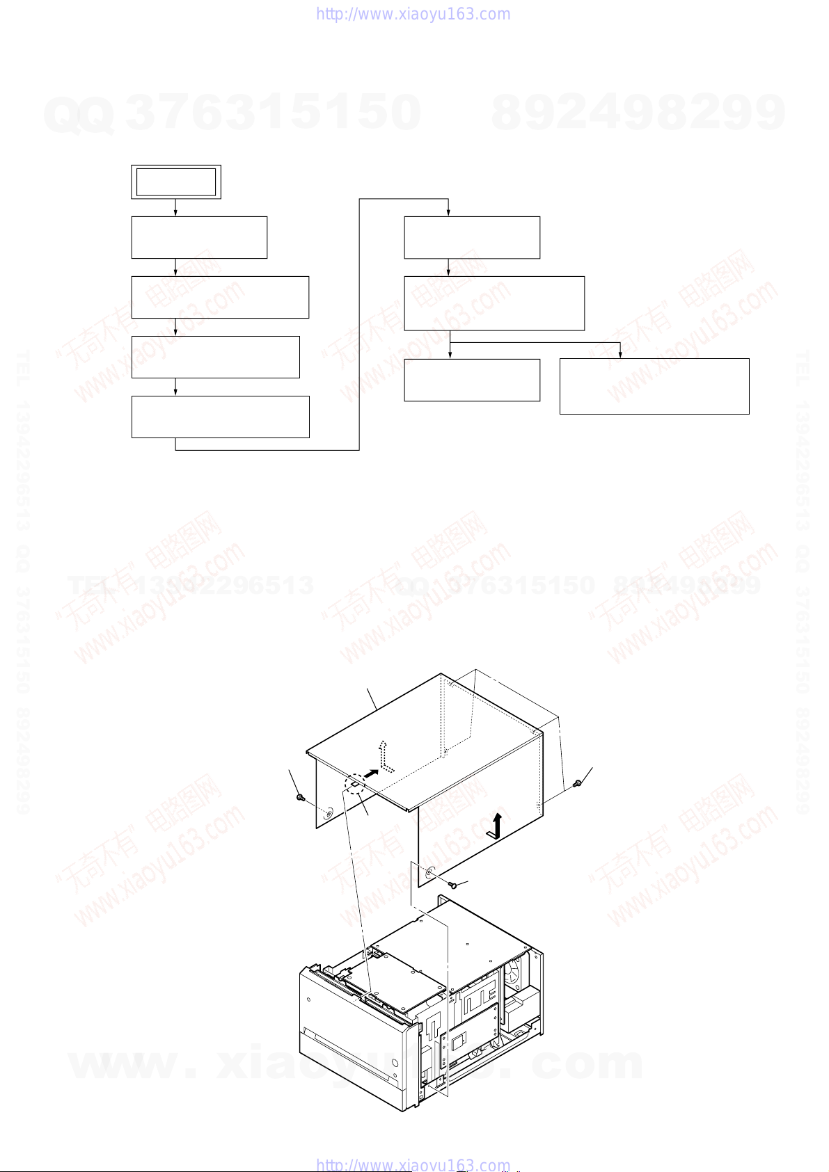
• This set can be disassembled in the order shown below.
7
Q
3
3-1. DISASSEMBLY FLOW
6
SET
3
1
5
1
SECTION 3
DISASSEMBLY
5
0
8
9
HCD-DH3/DH5BT/DH7BT
2
4
9
8
2
9
9
3-2. STEEL CABINET
(Page 13)
3-3. FRONT PANEL SECTION
(Page 14)
TEL 13942296513 QQ 376315150 892498299
Note: Follow the disassembly procedure in the numerical order given.
TEL
3-2. STEEL CABINET
3-4. BACK PANEL SECTION
(Page 14)
3-5. MAIN CHASSIS SECTION
(Page 15)
13942296513
3-6. DMB15 BOARD
(Page 15)
3-7. DVD MECHANISM DECK
(CDM86-DVBU101)
(Page 16)
3-8. BELT (MOT)
(Page 16)
7
3
Q
Q
6
3
1
3-9. OPTICAL PICK-UP BLOCK
(KHM-313CAB)
(Page 17)
2
9
8
0
5
1
5
4
9
8
2
9
TEL 13942296513 QQ 376315150 892498299
9
w
w
w
.
xia
3
screw
(BTP3
6
steel cabinet
4
claw
u
5
1
6
2
3
5
screw
(BTP3
.
×
8)
c
×
8)
o
y
o
1
four screw
(BV/RING)
m
13
)
HCD-DH3/DH5BT/DH7BT
Ver. 1.2
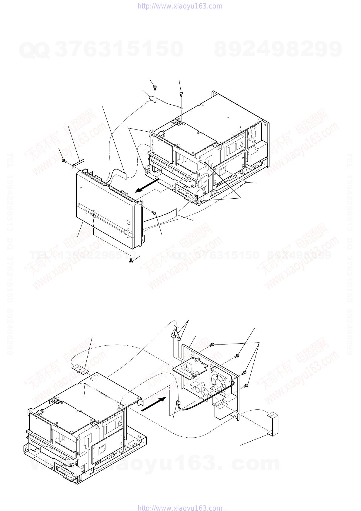
3-3. FRONT PANEL SECTION
7
Q
Q
5
screw
TEL 13942296513 QQ 376315150 892498299
(BVTP3
3
6
×
8)
coating clip
6
9
wire (flat type) (9 core)
(CN702)
3
1
qs
earth cable
5
qa
7
two claws
1
screw
(BV3)
8
5
0
0
screw
(BVTP3
×
8)
8
9
2
4
2
coaxial cable terminal
(DH5BT/DH7BT)
9
8
2
9
9
TEL 13942296513 QQ 376315150 892498299
qd
front panel section
TEL
3-4. BACK PANEL SECTION
13942296513
2
wire (flat type) (15 core)
(MAIN board: CN304, XM board: CN001)
(DH7BT)
3
two screws
(BVTP3
4
screw
(BVTP3
Q
Q
×
8)
1
wire (flat type) (15 core)
(CN307)
×
8)
3
6
7
3
6
two connectors
(CN850, CN870)
8
back panel section
1
5
7
1
two claws
0
5
4
9
8
screw
(BVTP3
3
five screws
(BVTP3 × 10)
9
4
2
×
10) (DH7BT
8
2
9
9
14
w
w
w
.
xia
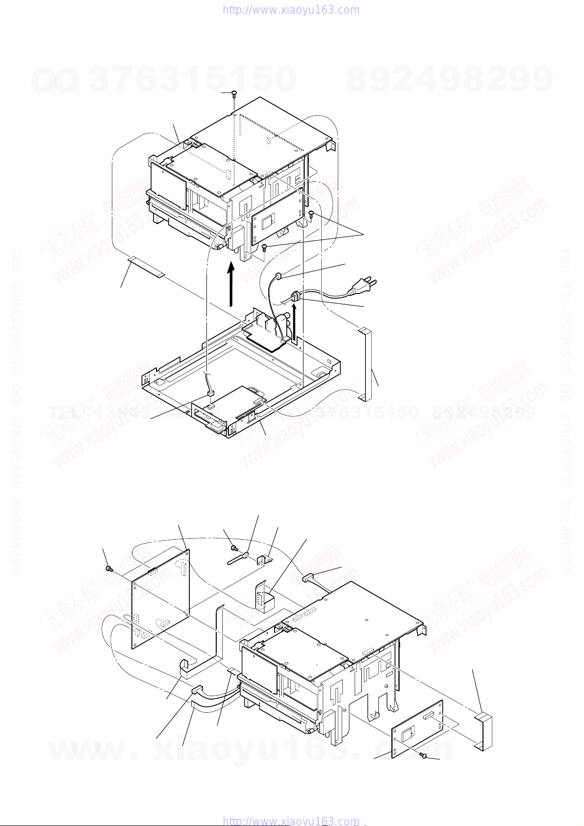
5
7
connector
(CN203)
1
wire (flat type) (9 core)
(DH3/DH5BT: Canadian, Russian, Australian, Chinese,
Singapore, Taiwan, Korean, Thai/DH7BT),
wire (flat type) (11 core)
o
y
u
(DH5BT: AEP)
1
6
3
(MAIN board: CN110, tuner (FM/AM))
.
c
o
m
)
3
BT board
(DH5BT/DH7BT)
1
wire (flat type) (15 core)
(DH5BT/DH7BT)
(MAIN board: CN306, BT board: CN901)
5
wire (flat type) (19 core)
(MAIN board: CN302,
DMB15 board: CN302)
6
wire (flat type)
(24 core) (CN101)
4
connector
(CN401)
7
connector
(CN201)
2
two screws
(BVTP3 × 8)
(DH5BT/DH7BT)
q;
two screws
(BVTP3 × 8)
qa
screw
(BVTP3 × 8)
qs
coating clip
qd
plate (GND DVD)
8
wire (flat type)
(7 core) (CN202)
9
wire (flat type) (13 core)
(MAIN board: CN301,
DMB15 board: CN106)
qf
DMB15 board
3-5. MAIN CHASSIS SECTION
7
Q
Q
TEL 13942296513 QQ 376315150 892498299
3
9
2
wire (flat type) (13 core)
(DMB15 board: CN301,
VIDEO board: CN501)
6
holder (CDM) section
3
1
5
5
screw
(BV3)
7
1
5
0
2
9
8
4
two screws
(BV3)
1
connector (CN204)
6
Lift up the
cord bushing (2104).
HCD-DH3/DH5BT/DH7BT
4
9
8
2
9
9
TEL 13942296513 QQ 376315150 892498299
TEL
13942296513
8
connector
(CN904)
(DH3/DH5BT)
3-6. DMB15 BOARD
3
Q
Q
main chassis section
q;
7
6
3
3
wire (flat type) (11 core) (DH3/DH5BT)
(MAIN board: CN305, USB board: CN905
4
2
9
8
0
5
1
5
1
9
8
2
9
9
w
w
w
.
xia
o
y
u
1
6
3
.
c
o
m
15
k
HCD-DH3/DH5BT/DH7BT
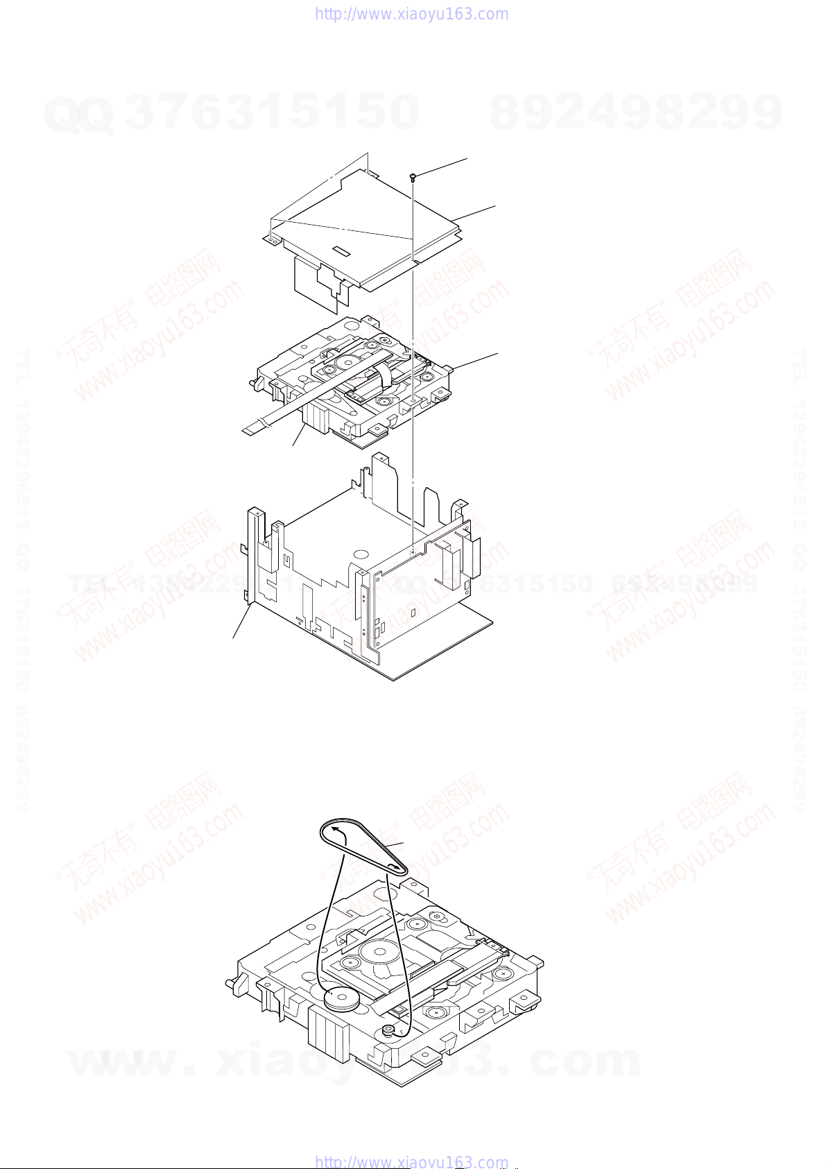
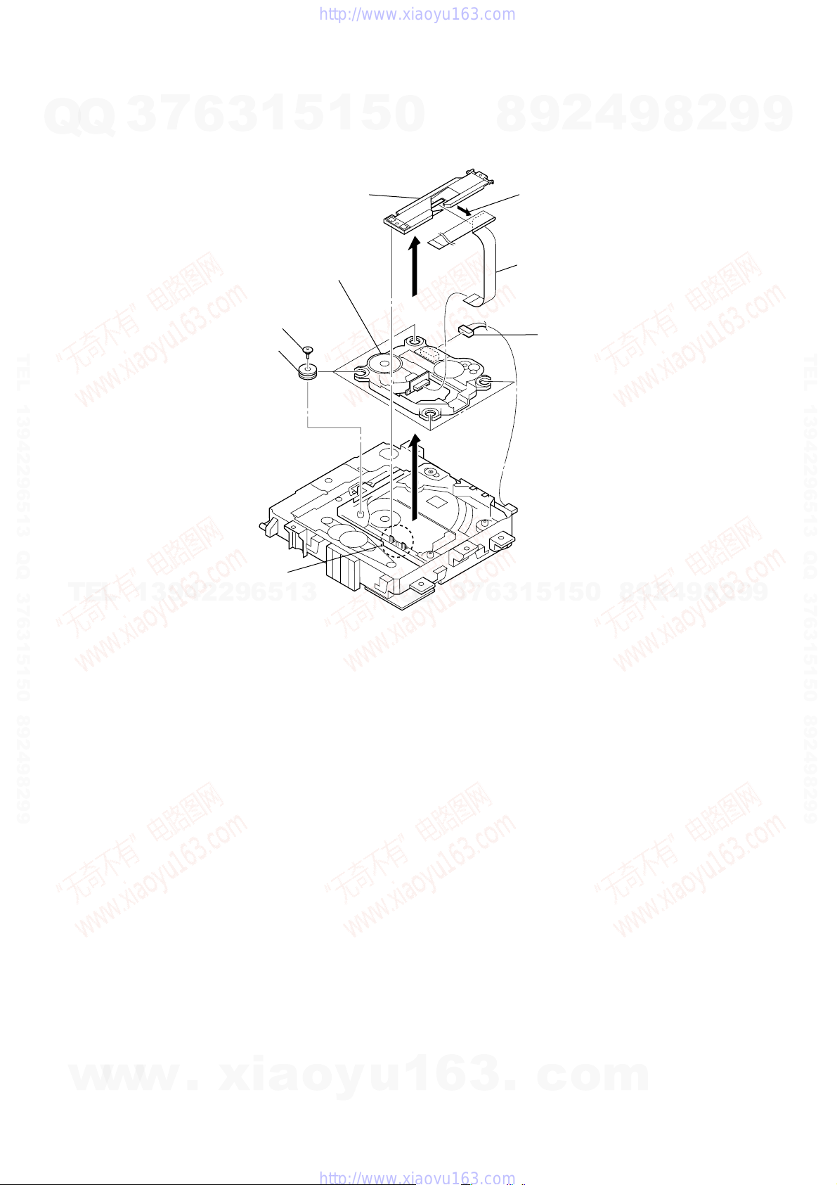
3-7. DVD MECHANISM DECK (CDM86-DVBU101)
Q
Q
3
7
6
3
1
5
1
5
0
8
1
three screws
(BVTP3
2
2
9
×
8)
cover (mecha L)
4
9
8
2
9
9
TEL 13942296513 QQ 376315150 892498299
DVD mechanism deck
bottom view
TEL
13942296513
holder (CDM) section bottom view
Q
Q
3
7
3
DVD mechanism dec
(CDM86-DVBU101)
5
1
3
6
1
5
0
8
9
2
4
9
8
2
9
TEL 13942296513 QQ 376315150 892498299
9
3-8. BELT (MOT)
w
w
w
16
.
xia
1
belt (MOT)
o
y
u
1
6
– DVD mechanism deck (bottom view) –
3
.
c
o
m
3-9. OPTICAL PICK-UP BLOCK (KHM-313CAB)
7
Q
Q
TEL 13942296513 QQ 376315150 892498299
3
6
6
four insulator screws
8
four insulators
1
3
9
optical pick-up block
(KHM-313CAB)
5
3
FFC holder
1
5
0
8
HCD-DH3/DH5BT/DH7BT
4
2
9
1
Remove the wire (flat type) (24 core)
of FFC holder.
4
wire (flat type) (24 core)
5
connector
9
8
2
9
9
TEL 13942296513 QQ 376315150 892498299
TEL
2
two claws
13942296513
7
3
6
7
3
Q
Q
– DVD mechanism deck (bottom view) –
1
5
1
5
0
8
9
2
4
9
8
2
9
9
w
w
w
.
xia
o
y
u
1
6
3
.
c
o
m
17
HCD-DH3/DH5BT/DH7BT
Ver. 1.1
SECTION 4
TEST MODE
COLD RESET
The cold reset clears all data including preset data stored in the
Q
Q
RAM to initial conditions.
Procedure:
1. Press the I/1 button to turn on the system.
2. Press three buttons of x , [DISPLAY] and I/1 simultaneously.
3. The message “RESET” appears on the fluorescent indicator
tube, and the system is reset.
PANEL TEST MODE
This mode is used to check the fluorescent indicator tube, LEDs,
keys, model, destination and software version.
Procedure:
1. Press three buttons of x , [VOLUME --] and [DISPLAY]
simultaneously.
2. All LEDs and segments in fluorescent indicator tube are lighted
TEL 13942296513 QQ 376315150 892498299
up.
3. Press the [DISPLAY] button, the software version display mode
is activated, and model and destination information appears
on the fluorescent indicator tube.
4. In the software version display mode, each time the [DISPLAY]
button is pressed, the display changes from MC version,
MMLib version, Bolero version in this order, and returns to
the model and destination information (DH3/DH5BT).
In the software version display mode, press the [DISPLAY]
button, MC version appears on the fluorescent indicator tube.
Also, press the [DISPLAY] button again, the display returns to
the model and destination information (DH7BT).
5. Press the [DSGX] button, the key check mode is activated,
“KEY 0 0 0” appears on the fluorescent indicator tube.
6. In the key check mode, each time a button is pressed, the
numerical value corresponding to each button is displayed on
the fluorescent indicator tube.
TEL
7. To release from this mode, press three buttons in the same
manner as step 1 or disconnect the power cord.
3
7
6
3
1
13942296513
5
1
5
DVD COLOR SYSTEM
This mode let you change the color system of the video output from
0
PAL to NTSC or vice-versa. This mode is not available for US,
Canadian, AEP and Russian models.
Procedure:
1. Press the I/1 button to turn on the system.
2. Press the DVD N button to select the “DVD”.
3. Press the I/1 button to turn off the system.
4. Press two buttons of X and I/1 simultaneously. The system
will turn on automatically. The message “COLOR PAL” or
“COLOR NTSC” appears on the fluorescent indicator tube.
BT TEST MODE
This mode is used to check the firmware version and address of
bluetooth module. This mode is not available for HCD-DH3.
Procedure:
1. Press the I/1 button to turn on the system.
2. Press the BLUETOOTH N or [BLUETOOTH] button to select
“BLUETOOTH”.
3. Press three buttons of x , [DSGX] and [BLUTOOTH OPR]
simultaneously, the message “BT Test In” is displayed on the
fluorescent indicator tube. Then, the display is automatically
changed to the firmware version of bluetooth.
4. Press the [DISPLAY] button, address of bluetooth device is
displayed on the fluorescent indicator tube.
5. To release this mode, press the I/1 button.
7
3
Q
Q
8
6
3
9
1
5
2
1
5
4
0
9
8
9
8
2
4
2
9
8
9
2
9
9
TEL 13942296513 QQ 376315150 892498299
9
TUNER STEP CHANGE
The step interval of AM channels can be toggled between 9 kHz
and 10 kHz. This mode is not available for AEP and Russian models.
Procedure:
1. Press the I/1 button to turn on the system.
2. Press the [TUNER/BAND] button to select the “AM”.
3. Press the I/1 button to turn off the system.
4. Press two buttons of [TUNER/BAND] and I/1 simultaneously.
The system will turn on automatically. The message “AM 9k
Step” or “AM 10k Step” appears on the fluorescent indicator
tube and thus the channel step is changed.
DISC ANTITHEFT
This mode is used to lock the disc slot. When this mode is acti vated,
the disc will not slot out when Z button is pressed. The message
“LOCKED” appears on the fluorescent indicator tube.
Procedure:
1. Press the I/1 button to turn on the system.
2. Press the DVD N button to select the “DVD”.
3. Press two buttons of x and Z simultaneously and hold down
until “LOCKED” or “UNLOCKED” appears on the
fluorescent indicator tube (around 5 seconds).
18
w
w
w
.
xia
o
y
u
1
6
3
.
c
o
m
HCD-DH3/DH5BT/DH7BT
DVD SECTION
7
Q
Q
TEL 13942296513 QQ 376315150 892498299
TEL
3
1. DVD SER VICE MODE GENERAL DESCRIPTION
This mode let you make diagnosis and adjustment easily by using
the remote commander and the TV screen. The instructions,
diagnostic results, etc. are given on the on-screen display.
2. ENTERING DVD SERVICE MODE
Procedure:
1. Press the I/1 button to turn on the system.
2. Press the DVD N button to select the “DVD”.
3. Press three buttons of x , [VOLUME +] and [PROGRESSIVE]
simultaneously.
4. The message “SERVICE IN” appears on the fluorescent
indicator tube and top menu of the Remocon Diagnosis Menu
appears on the on-screen display on the TV screen as follows.
The model name, IF-con version and Syscon version are
displayed at the bottom of the on-screen display.
0. External Chip Check
1. Servo Parameter Check
2. Drive Manual Operation
3. Emergency History
4. Version Information
Model Name :DH_xx
IF-con:Ver.xx.xx(xxxx)
Syscon:Ver.x.xxx
13942296513
5. To execute each function, press its number by using numeric
button on the remote commander.
6. To release from this mode, press the
system.
3. EXECUTING IOP MEASUREMENT
In order to execute IOP measurement, the following standard
procedures must be followed.
Procedure:
1. From the top menu of Remocon Diagnosis Menu, select “2
Drive Manual Operation” by pressing the [2] button on the
remote commander. The following screen appears on the onscreen display
1. Servo Control
2. Track/Layer Jump
3. Manual Adjustment
4. Tray Aging Mode
5. MIRR time Adjust
0. Return to Top Menu
6
Remocon Diagnosis Menu
Drive Manual Operation
3
1
5
1
5
I/1 button to turn off the
0
Q
Q
3. Select “6. Iop:” by pressing [6] button on the remote
4. Wait until a hexadecimal number appear in the on-screen
7
3
5. Convert data from hexadecimal to decimal by using conversion
6. If the value is smaller than 93 (decimal), then it is OK. Howev er
7. Press the
8. Press the [0] button on the remote commander to return to the
9. Press the I/1 button to turn off the system.
4. CHECKING EMERGENCY HISTORY
To check the emergency history, please follow the following
procedure.
Procedure:
1. From the top menu of Remocon Diagnosis Menu, select “3.
Manual Adjust
4
2
9
8
1. Track Balance Adjust:
2. Track Gain Adjust:
3. Focus Balance Adjust:
4. Focus Gain Adjust:
5. Eq boost Adjust:
6. Iop:
7. TRV. Level:
8. S curve(FE) Level:
9. RFL(PI) Level:
0. MIRR Time:
V v Change Value
[RETURN]Return to previous menu
commander.
display as below.
1. Track Balance Adjust:
2. Track Gain Adjust:
3. Focus Balance Adjust:
4. Focus Gain Adjust:
5. Eq boost Adjust:
6. Iop: 57
7. TRV. Level:
8. S curve(FE) Level:
9. RFL(PI) Level:
0. MIRR Time:
V v Change Value
[RETURN]Return to previous menu
5
1
3
6
table.
if the value is higher than 93, then BU (base unit) is defectiv e
and need to be change.
O RETURN button on the remote commander to
return to previous menu.
top menu of Remocon Diagnosis Menu.
Emergency History” by pressing the [3] button on the remote
commander. The following screen appears on the on-screen
display.
Laser Hours CD 999h 59min
DVD 999h 59min
0
5
1
Emg. History Check
9
Manual Adjust
2
9
8
8
4
2
9
8
9
2
9
9
9
TEL 13942296513 QQ 376315150 892498299
2. Select “3. Manual Adjustment” by pressing the [3] button on
the remote commander. The following screen appears on the
w
on-screen display.
w
w
.
xia
o
y
u
1
6
01. 01 05 04 04 00 92 46 00
00 00 00 00 00 00 23 45
02. 02 02 01 01 00 A9 4B 00
00 00 00 00 00 00 23 45
3
.
c
o
[Next]Next page [Prev]Prev page
[0]Return to Top Menu
m
19
HCD-DH3/DH5BT/DH7BT
2. Y ou can check the total time when the laser is turned on during
playback of DVD and CD from the above menu. The maximum
Q
Q
time, which can be displayed are 999h 59min.
3. You can check the error code of latest 10 emergency history
from the above menu. To view the previous or next page of
emergency history, press the . or > button on the
remote commander. The er ror code consists of three kinds of
error codes.
A. Error code
01. 01 05 04 04 00 92 46 00
00 00 00 00 00 00 23 45
TEL 13942296513 QQ 376315150 892498299
The meaning of error code is as below:
01: Communication error (No reply from syscon)
02: Syscon hung up
03: Power OFF request when syscon hung up
19: Thermal shutdown
24: MoveSledHome error
25: Mechanical move error (5 changer)
26: Mechanical move stack error
30: DC motor adjustment error
31: DPD offset adjustment error
32: TE balance adjustment error
33. TE sensor adjustment error
34. TE loop gain adjustment error
35. FE loop gain adjustment error
36. Bad jitter after adjustment
40. Focus NG
42. Focus layer jump NG
TEL
52. Open kick spindle error
51: Spindle stop error
60: Focus on error
61: Seek fail error
62: Read Q data/ID error
70: Lead in data read fail
71: TOC read time out (CD)
80: Can’t buffering
81: Unknown media type
B. Parameter of error code
This is the detail of error code.
01. 01 05 04 04 00 92 46 00
00 00 00 00 00 00 23 45
7
3
Example of Error code
6
3
1
13942296513
Example of Error code
5
1
5
To Clear the Laser Hour
Press the [ DISPLAY] button on the remote commander and then
0
press the [CLEAR] button on the remote commander. The data for
both CD and DVD data are reset.
Laser Hours CD 0h 0min
DVD 0h 0min
01. 01 05 04 04 00 92 46 00
00 00 00 00 00 00 23 45
02. 02 02 01 01 00 A9 4B 00
00 00 00 00 00 00 23 45
[Next]Next page [Prev]Prev page
[0]Return to Top Menu
To Clear the Emergency History
Press the [DVD TOP MENU] button on the remote commander and
then press the [CLEAR] button on the remote commander. The error
code for all emergency history would be reset.
Laser Hours CD 999h 59min
DVD 999h 59min
01. 00 00 00 00 00 00 00 00
00 00 00 00 00 00 00 00
02. 00 00 00 00 00 00 00 00
00 00 00 00 00 00 00 00
7
3
Q
Q
[Next]Next page [Prev]Prev page
[0]Return to Top Menu
To Return to the Top Menu of Remocon Diagnosis
Menu
Press the [0] button on the remote commander.
5. CHECKING VERSION INFORMATION
To check the version information, please follow the following
procedure.
Procedure:
1. From the top menu of Remocon Diagnosis Menu, select “4.
Version Information” by pressing the [4] button on the remote
commander. The following screen appears on the on-screen
display.
2
9
8
Emg. History Check
Emg. History Check
0
5
1
5
1
3
6
4
9
8
9
8
2
4
2
9
8
9
2
9
9
TEL 13942296513 QQ 376315150 892498299
9
C. Time of error code
This is the laser time when an error occurred.
Example of Error code
01. 01 05 04 04 00 92 46 00
00 00 00 00 00 00 23 45
w
w
w
20
.
xia
Firm(Main): Ver. X.XXX
Firm(Sub): XX.XX
RISC: XXXXXX
8032: XXXXXX
Audio DSP: XX.XX.XX.XX
Servo DSP: XX.XX.XX.XX
[0]Return to Top Menu
o
y
u
1
6
2. To return to the top menu of Remocon Diagnosis Menu, press
3
the [0] on the remote commander.
Version information
.
c
o
m

SECTION 5
e
V
e
ELECTRICAL CHECKS
HCD-DH3/DH5BT/DH7BT
TUNER SECTION
Q
FM TUNE LEVEL CHECK
Procedure:
TEL 13942296513 QQ 376315150 892498299
When the selected station signal is received in good condition,
“TUNED” is displayed.
Q
generator
1. Turn on the set.
2. Input the following signal from signal generator to FM antenna
input directly.
Carrier frequency: A = 87.5 MHz, B = 98 MHz, C = 108 MHz
Deviation : 75 kHz
Modulation : 1 kHz
ANT input : 35 dBu (EMF)
Note: Use 75 ohm coaxial cable to connect signal generator and the set.
You cannot use video cable for checking.
Use signal generator whose output impedance is 75 ohm.
3. Set to FM tuner function and tune A, B and C signals.
4. Confirm “TUNED” is lit on the display for A, B and C signals.
3
signal
7
set
6
3
1
Connecting Location:
– DMB15 Board (Side A) –
5
CN105
16
IC201
1
5
level:
0.58
(DVD-SL)
0.57 ± 1.1 Vp-p
(CD)
IC102
VOLT/DIV: 200 m
TIME/DIV: 500 ns
0
±
1.23 Vp-p
8
9
2
4
9
8
2
9
9
TEL 13942296513 QQ 376315150 892498299
DVD SECTION
TEST DISC LIST
T
E
Be sure to use the DVD disc that matches the signal standards of
your region.
• CD
YEDS-18 (Part No.: 3-702-101-01)
PATD-012 (Part No.: 4-225-203-01)
• DVD SL (Single Layer)
HLX-503 (NTSC) (Part No.: J-6090-069-A)
HLX-504 (NTSC) (Part No.: J-6090-088-A)
HLX-506 (PAL) (Part No.: J-6090-077-A)
• DVD DL (Dual Layer)
HLX-501 (NTSC) (Part No.: J-6090-071-A)
HLX-505 (NTSC) (Part No.: J-6090-089-A)
HLX-507 (PAL) (Part No.: J-6090-078-A)
RFMON LEVEL CHECK
Connection :
CN105 pin
Procedure :
1. Connect an oscilloscope to CN105 pin 6 (RFMON) and
CN105 pin 3 (GND) on the DMB15 board.
2. Press the I/1 button to turn on the system.
3. Insert the test disc (refer to “TEST DISC LIST”) and press
the DVD N button to playback.
4. Confirm that oscilloscope waveform is clear and check
RFMON signal level is correct or not.
Note: A clear RFMON signal wa veform means that the shape “◊” can be
w
clearly distinguished at the center of the waveform.
L
DMB15 board
6
CN105 pin
w
(RFMON)
3
(GND)
1
3
w
9
4
oscilloscop
+
–
.
2
2
x
9
6
5
1
3
VIDEO SECTION
VIDEO LEVEL CHECK
Purpose :
This adjustment is made to satisfy the NTSC standard, and if not
adjusted correctly, the brightness will be too large or small.
Oscilloscop
75
Ω
set
VIDEO board
VIDEO OUT jack (J502)
Procedure :
1. Connect an oscilloscope to VIDOE OUT jack (J502) on the
VIDEO board.
2. Press the I/1 button to turn on the system.
3. Insert the test disc (refer to “TEST DISC LIST”) and press
the DVD N button to playback.
4. Confirm the video signal level is 1.00 ± 0.07 Vp-p.
1.00 ± 0.07 Vp-p
i
a
o
y
u
Q
1
Q
6
3
7
3
6
.
3
1
5
c
1
5
o
0
m
8
9
2
4
9
8
2
9
9
HCD-DH3/DH5BT/DH7BT
(WHITE 100%)
2121
HCD-DH3/DH5BT/DH7BT
Ver. 1.2
6-1. BLOCK DIAGRAM – RF SERVO/VIDEO Section –
Q
Q
3
SECTION 6
DIAGRAMS
7
6
3
1
5
1
5
0
D/A CONVERTER
IC301
8
9
2
4
9
8
2
9
9
RF
VOA/A
VOB/B
VOC/C
VOD/D
OPTICAL PICK-UP
BLOCK
(KHM-313CAB)
TEL 13942296513 QQ 376315150 892498299
PD
AUTOMATIC POWER
CONTROL (FOR CD)
Q102-1
AUTOMATIC POWER
CONTROL (FOR DVD)
Q102-2
MSW
IC201
9
Q103
6
T
E
L
1
VR (780)
3
9
CD ON
SWITCH
Q101-1
DVD ON
SWITCH
Q101-2
4
2
2
FOCUS/TRACKING COIL DRIVE,
SLED/SPINDLE/LOADING MOTOR DRIVE
5
6
8
9
10
11
22LD (650)
50VR (650)
176LIMIT
ASDATA0 217 LOUT1+ 2
DVDRFIP
MA
MB
MC
MD
DVDA2
DVDB3
DVDC4
DVDD5
TNI18VOE/E+G
TPI19VOF/F+H
V2O29VC
MDI120
MDI221
LDO123LD (780)
LDO2
RF AMP, SERVO DSP,
MSW
LIMSW
1
SPDIF 225
MPEG DECODER
IC102
YUV3
YUV2
3
YUV1
5
SDA
EEPROM
IC103
198
196
194
15ASDATA1 218
16ASDATA2 219
10ACLK 215
9ABCK 214
17ALRCK 213
8XRST 220
20SDA 103
19SCL 102
6
SCL
SDTI114
SDTI2
SDTI3
SDTI413ASDATA4 222 LOUT4+ 38
MCLK
BICK
LRCK
PDN
SDA
SCL
LOUT1– 1
ROUT1+
ROUT1–
LOUT4– 37
ROUT4+
DIGITAL OPTICAL
TRANSCEIVER
IC208
Q
Q
48
47
33
32ROUT4–
DIGITAL OUT
OPTICAL
3
7
MIX AMP
IC3711
MIX AMP
IC3771
6
3
R-CH
+
1
CENTER VOLTAGE
GENERATOR
Q3801
1
5
VIDEO AMP, 75 DRIVER
4
CVBS IN
2
C IN
5
6
Y IN
AU+5V
0
IC501
CVBS OUT
C OUT
S-DC OUT
8
Y OUT
DVD-L
B
(Page 24)
MUSIC L+R
(Page 25)
DH3/DH5BT: AEP, Russian, Australian,
Chinese, Singapore, Taiwan, Korean, Thai
• R-ch is omitted due to same as L-ch.
• SIGNAL PATH
: CD PLAY
: DVD PLAY
: DIGITAL OUT
: AUDIO
: VIDEO
: Y
: CHROMA
: COMPONENT VIDEO
2
J502
VIDEO
OUT
J501
S VIDEO
9
OUT
23
26
27
21
9
2
CY
9
4
8
C
TEL 13942296513 QQ 376315150 892498299
9
w
XVOICE, SCORE
A
(Page 25)
DH3/DH5BT: AEP, Russian, Australian,
w
w
Chinese, Singapore, Taiwan, Korean, Thai
FCS+
FCS– 37
TRK+ 35
TRK– 34
SL+ 29
SL– 30
SP+ 27
SP– 28
M001
(LOADING)
M
REGO2
REGO1
.
36
46
47
24
42
31
32
FOCUS
COIL DRIVE
TRACKING
COIL DRIVE
SLED
MOTOR DRIVE
SPINDLE
MOTOR DRIVE
BUFFER
LOADING
MOTOR DRIVE
BUFFER
REGULATOR
x
MUTE5
i
19
RCS /CS
CKSW
16
138
RWE /WE
(DISC IN/OUT)
10
12
14
S101
CY IN
CB IN
CR IN
OCSW
177
o
S1
25
49
48
WIDE
32
MUTE113MUTE2
I/P
3
9
DSEL
9
I-MTK SL IN
m
O-VID MUTE
200
1
4
10
13
45
16
17
15
19
21
20
22
40
8
FOO42
TRO41
FMO38
DMO37
SPFG47
FWD17425
REV178
TROPENPWM39
MUTE123MUTE12 211
MUTEMUTE34 210
TSD_MTSD-M 170
IOPMON40
RF+3.3V
a
YUV4
YUV5
YUV6
o
VOICE
206
XVOICE
202
203
SMSCK
208
SCORE
DQ0 – DQ15
2, 4, 5, 7, 8, 10, 11, 13, 42,
44, 45, 47, 48, 50, 51, 53
125 – 123, 121, 120, 118, 117,
115, 135, 133 – 128, 126
RD0 – RD15
AD0 – AD7
81 – 84,
86 – 88, 91
29, 31, 33, 35,
38, 40, 42, 44
DQ0 – DQ7
y
72 – 67, 92, 60, 61, 76, 89
u
147, 149 – 151, 166 – 164,
162, 160, 159, 146, 158
IOA0 – IOA21
93, 78, 53 – 59, 75, 74,
45, 25 – 18, 8 – 1,
48, 17, 16, 9, 10
A-1, A0 – A20
FLASH ROM
IC101
1
SD-RAM
IC104
A0 – A11
23 – 26,
29 – 34, 22, 35
RA0 – RA11
IOCSCE
77
79
26
28
6
20
21
38
37
15
39
18
17
143
145
156
157
113
137
140
139
142
BA0 BA0
BA1 BA1
CKE CKE
RCLK CLK
IOOEOE
IOWRWE
XTALI
X101
27MHz
228
XTALO
.
104
S103
(TRIGGER)
66
229
11
3
DQM0 LDQM
DQM1 UDQM
TRG-SW
CAS /CAS
RAS /RAS
179
S102
(CHUCKING)
c
20
CY OUT
18
CB OUT
16
CR OUT
98
100
101
99
105
45
27
44
46
31
I-MTK DI IFSDO
I-MTK CLK IFCK
I-MTK-XIFCS IXFCS
O-MTK DATA IFSDI
SYSTEM CONTROLLER
IC101 (1/5)
O-MTK-IFBSY IFBSY
Y
PB/CB
PR/CR
205
207
110
29
28
26
O-MTK RST PRST
O-MTK MICR MIC
I-MTK KRMOD KRMOD
J503
COMPONENT
VIDEO OUT
HCD-DH3/DH5BT/DH7BT
2222
6-2. BLOCK DIAGRAM – TUNER/USB/BLUETOOTH Section –
VBUS
+5V
7
79 D+
80 D–
77 USBOC
78 USBPON
6
USB CONTROLLER
IC901
3
93DATA 30LO
92BCK
71LRCK
94GATE
97ST-REQ
55BUS0
56BUS1
57BUS2
58BUS3
59/BUCK
60/CCE
96REQ
61/RST
88RXD1
87TXD1
EN
IC915
1
FLG
IN
3
3
4OUT
Q
CN902
(USB)
3
2
1
Q
D+
D–
VBUS
VBUS POWER
ON/OFF SWITCH
5
TEL 13942296513 QQ 376315150 892498299
S-RAM
IC921
1
65 AIN (PI4)
66 BCKi (PI5)
67 LRCKi (PI6)
51 PIO3
46 AoUT3 (PO4)
38 BUS0
39 BUS1
40 BUS2 (SO)
41 BUS3 (SI)
42 BUCK (CLK)
43 XCCE
48 PIO0
37 XRST
MP3 PROCESSOR
IC951
XOXI
2423
X951
16.9344MHz
5
27RO
R-CH
1
5
SC-RX-IN
0
SYSTEM CONTROLLER
IC101 (2/5)
SC-TX-OUT
76 O-XM TXD/O-USB TXD
77 I-XM RXD/I-USB RXD
(DH3/DH5BT)
USB-L
SC-RX-IN,
SC-TX-OUT
D
(Page 24)
E
(Page 24)
(DH7BT)
8
9
2
4
9
8
HCD-DH3/DH5BT/DH7BT
2
9
9
TEL 13942296513 QQ 376315150 892498299
T
E
L
(FOR BLUETOOTH)
ANT901
PATTERN
ANTENNA
I/O0 – I/O15
7 – 10, 13 – 16,
A0 – A15
44 – 42, 27 – 24,
CE 6
OE 41
WE 17
LB
39
UB 40
29 – 32, 35 – 38
21 – 18, 5 – 1
1
3
D0 – D15
18 – 25, 28 – 35
A1 – A16
37 – 43, 46 – 54
9
4
70 CS2
64
RD
65 WR
66 SRLLB
67 SRLUB
X1
75
X901
9MHz
IC904
BLUETOOTH MODULE
X2
73
2
10A_OUT_P_L
2
9A_OUT_N_L
8A_OUT_P_R
7A_OUT_N_R
9
R-CH
FM75Ω
COAXIAL
6
AM
ANTENNA
5
MIX AMP
IC902
1
3
TUNER (FM/AM)
FM ANT
AM ANT
PLL DO/STEREO
TUNER-L
TUNER-R
PLL DIN
PLL CLK
PLL CE
RDS DATA
RDS CLK
(DH5BT: AEP)
R-CH
79 I-USB RXD
60 O-USB SO2DI
61 I-USB SI84DO
8O-USB RST1/RESET
Q
7 I-ST DI
87 O-ST DATA
88 O-ST CLK
85 O-ST CE
6 I-RDS SI
5 I-RDS CLK
Q
3
TUNER-L
7
BT-L
(Page 24)
F
6
G
(Page 24)
3
1
5
1
5
0
8
9
2
4
9
8
2
9
9
w
HCD-DH3/DH5BT/DH7BT
w
w
.
5A_IN_P_L
4A_IN_N_L
3A_IN_P_R
2A_IN_N_R
40UART_RXD
41UART_TXD
38UART_CTS
39UART_RTS
x
46RESET
R-CH
i
LINE AMP
IC901
a
o
y
72 O-BT TXD
71 I-BT RXD
80 I-BT RXD
67 O-BT RTS
66 I-BT CTS
65 O-BT AV ROL12PIO_00
u
1
68 O-BT REST
6
2323
BT OUT-L
3
(DH5BT/DH7BT)
H
(Page 24)
.
R-ch is omitted due to same as L-ch.
SIGNAL PATH
: AUDIO
: TUNER (FM/AM)
: USB
c
: BLUETOOTH IN
: BLUETOOTH OUT
o
m
HCD-DH3/DH5BT/DH7BT
6-3. BLOCK DIAGRAM – MAIN Section –
Q
J702
AUDIO IN
DVD-L
B
(Page 22)
TUNER-L
F
(Page 23)
USB-L
D
(Page 23)
TEL 13942296513 QQ 376315150 892498299
(DH3/DH5BT)
BT-L
G
(Page 23)
(DH5BT/DH7BT)
SC-RX-IN,
SC-TX-OUT
E
(Page 23)
T
Q
J001
XM
3
2
E
1
R-CH
D+
D–
L
VCC
3
1
7
3
XM RECEIVER
18 COMM_RX_P
19 COMM_RX_N
23 COMM_TX_P
COMM_TX_N
22
9
4
OSC_IN
X001
45.158MHz
6
IC001
2
OSC_OUT
2628
I2S_OCLK
SC_TX_OUT
SC_RX_IN
3
5
SC-RX-IN
SC-TX-OUT
2
3
RST#
11
37I2S_DA
39I2S_CLK
41I2S_LRCLK
43
XM
+3.3V
9
1
6
B+ SWITCH
Q001, 003
B+ SWITCH
Q223
5
5
D/A CONVERTER
IC041
3 SDTI
2 BICK
4 LRCK
MCLK
1
1
XM
+5.4V
D216
+4V
AOUTR
3
PDN
1
11AOUTL
R-CH
10
5
5
LINE AMP
IC051
0
(DH5BT)
Q
Q
(DH3)
INPUT SELECTOR
IC302
Y2
2
Y0
1
Y1
5
10A9
3
Q301
B
Q302
2
: AUDIO
: TUNER (FM/AM)
: USB
: XM
: SIRIUS
: AUDIO IN
: MIC
MUTING
Q307
R-CH
8
9
MUTING
CONTROL SWITCH
Q309, 310
R-CH
2
9
BT OUT-L
(DH5BT/DH7BT)
PHONES
9
L-CH
9
TEL 13942296513 QQ 376315150 892498299
H
(Page 23)
J703
9
K
(Page 25)
0
LOUT
4
8
27
MUTING
Q303
MUTING
CONTROL SWITCH
Q305, 306
R-CH
9
MUTING
9
8
R-ch is omitted due to same as L-ch.
SIGNAL PATH
HEADPHONE
AMP
IC303
Q315
R-CH
4
2
8
Y
3
3
6
7
9
INPUT SELECTOR, ELECTRICAL VOLUME,
5
1
+
2
SURROUND/TONE CONTROL
IC401
INL3
6
INL2
5
INL1
4
INL4
7
5
1
IGOUTL
8
VOLINL
9
DATA21CLK
22
6
3
(DH7BT)
MIC
J
(Page 25)
(DH3/DH5BT)
w
HCD-DH3/DH5BT/DH7BT
8
5
2
J301
SIRIUS
LEVEL SHIFT
IC304
w
R-CH
I-SIR RXD
42
O-SIR TXD43
w
B+ SWITCH
Q222
3
O-SIR POWER
.
XM
+5V
19
O-XM RST
x
i
4
O-XM 3.3V P-ON
a
18
o
O-XM 5V P-ON
24
I-AUDIO DET
y
O-SEL A15O-SEL B
IC101 (3/5)
6
u
(DH5BT/DH7BT)
SYSTEM CONTROLLER
1
2424
14
3
.
c
17
o
16
O-FUNC CLK
O-FUNC DATA
m
33
O-LINE MUTE
22
O-HP MUTE
23
I-HP DET
6-4. BLOCK DIAGRAM – KARAOKE/AMP Section –
Q
Q
3
7
6
(DH3/DH5BT: Australian, Chinese, Singapore, Taiwan, Korean, Thai)
DIGITAL ECHO
3
IC702
1
VR702
ECHO LEVEL
5
1
5
0
8
9
2
4
9
8
HCD-DH3/DH5BT/DH7BT
Ver. 1.2
2
9
9
(DH3/DH5BT)
J701
MIC
+11V
MUTING
Q702, 703
MIC AMP
IC701 (1/2)
VR701
MIC LEVEL
TEL 13942296513 QQ 376315150 892498299
MUSIC L+R
C
(Page 22)
T
K
(Page 24)
E
L-CH
X702
49.152MHz
A/D CONVERTER
LIN
1
SCKI
15
CLOCK SHIFT
IC703
CLOCK BUFFER
IC709
IC101 (4/5)
IC701
L
SYSTEM CONTROLLER
1
DOUT
BCK
LRCK
3
9
12
11
12
STREAM PROCESSOR
4
2
DATA
31
BCK
30
LRCK
29
XFSIIN
36
XFSOIN
48
IC705
2
OUTL1
OUTL2
OUTR1
OUTR2
9
6
11
9
6
4
5
BUFFER
Q701
4
6
14
16
DIGITAL POWER AMP
IC707
1
3
PWM_A
PWM_B
PWM_C
PWM_D
/RST_AB
15
5
OUT_A
OUT_B
OUT_C
OUT_D
/SD
/RST_CD
3
MIC AMP
IC701 (2/2)
AC/DC
CONVERTER
IC209 (2/2)
AC/DC
CONVERTER
IC209 (1/2)
33
30
25
22
A+9V
L.P.F.
L.P.F.
L.P.F.
L.P.F.
PROTECT
DETECT
Q701
COMPARATOR
IC211
COMPARATOR
IC210
Q
OVER LOAD
DETECT
Q702, 703
Q
OVER LOAD
DETECT
Q752, 753
MIC
(Page 24)
DH3/DH5BT: AEP, Russian, Australian,
Chinese, Singapore, Taiwan, Korean, Thai
XVOICE
SCORE
3
XVOICE, SCORE
7
J860
+
–
+
–
6
L
R
(Page 22)
3
SPEAKER
J
TEL 13942296513 QQ 376315150 892498299
A
9
9
2
8
9
4
2
9
1
5
1
5
0
8
w
HCD-DH3/DH5BT/DH7BT
w
I-MIC DET
O-SM DATA
O-SM SHIFT
O-SM LACH
O-SM PG MUTE
O-SM SOFT MUTE
O-SM NSP MUTE
O-SM INIT
O-SM RST
I-SM SD
25
(DH3/DH5BT)
38
39
40
34
35
48
49
36
37
w
.
21
22
23
20
19
18
27
SCDT
SCSHIFT
SCLATCH
PGMUTE
SOFTMUTE
NSPMUTE
INIT
x
i
a
o
y
R-ch is omitted due to same as L-ch.
SIGNAL PATH
: AUDIO
: MIC
u
1
6
2525
3
.
c
o
m
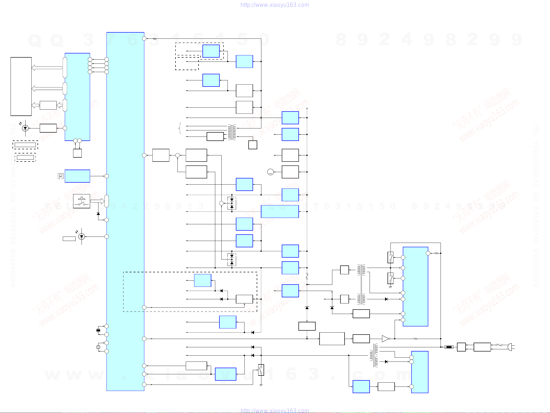
HCD-DH3/DH5BT/DH7BT
6-5. BLOCK DIAGRAM – PANEL/POWER SUPPLY Section –
59I-AC DET
FL901
FLUORESCENT
INDICATOR
TUBE
Q
Q
GRID DRIVE
Q904, 905
FLUORESCENT INDICATOR
32 – 43 61 – 64, 1 – 31
44, 45
TUBE DRIVER
IC902
CLKB
CSB
RSTB
SG1 – SG35
GR1 – GR12
GR13, GR14
3
DIN 55
54
53
52
TEL 13942296513 QQ 376315150 892498299
LED DRIVE
Q902
D903
USB MEMORY
(DH3)
BLUETOOTH
(DH5BT/DH7BT)
T
w
HCD-DH3/DH5BT/DH7BT
S901 – 919
E
57 P1
OSCI51OSCO
50
OSC
REMOTE CONTROL
RECEIVER
IC901
L
D902
STANDBY
w
1
D102
X102
20MHz
X101
32.768kHz
w
7
84
86
74
73
81 I-RMC
3
83 I-WAKE UP
70 O-SBY LED
95
94
92
91
O-FL DATA
O-FL CLK
O-FL CE
O-FL RST
I-KEY1 – KEY3
56 – 58
9
X1
X2
XT1
XT2
6
4
SYSTEM CONTROLLER
2
IC101 (5/5)
.
3
12I-PROTECT
2
41O-USB V-ON
75O-POWER
90RESET
10I-AC CUT
x
21O-DISCHARGE
FLUORESCENT
INDICATOR TUBE
(FL901)
PROTECT
DETECT
Q103
9
6
VBUS +5V (DH3/DH5BT)
XM +5.4V (DH7BT)
i
1
(DH5BT/DH7BT)
+3.3V
(DH7BT)
+3.3V
(FOR ADC )
AU+5V
+
RF+1.8V
SW+3.3V
5
+3.3V
RF+3.3V
SW+5V
+1.5V
DVDD
+3.3V
AVDD
+3.3V
+1.8V
+3.3V
µ-COM
+3.3V
EVER
+3.3V
a
BT
XM
+5V
AMP
+5V
+9V
F1
F2
VEE
+4V
5
OVER CURRENT
DETECT
Q201, 202, 204
OVER CURRENT
DETECT
Q229
1
3
+1.5V
REGULATOR
IC952
RESET SWITCH
Q102
o
+3.3V
REGULATOR
IC903
+3.3V
REGULATOR
IC702
RECT
D904, 905
1
T901
DC/DC CONVERTER
+
D209
D215
+1.8V
REGULATOR
IC704
RESET SIGNAL
GENERATOR
IC102
y
5
+5V
REGULATOR
IC207
+5V
REGULATOR
Q209
+5V
REGULATOR
Q210
+1.8V
REGULATOR
IC106
D202
+3.3V
REGULATOR
IC105
+3.3V
REGULATOR
IC107
D203
(DH3/DH5BT)
B+ SWITCH
Q226, 227
u
0
M+9V
OSC
Q903
+11V
(FOR HP AMP)
M201
M
(FAN)
+5V REGULATOR (DH3/DH5BT)
Q
+5.4V REGULATOR (DH7BT)
+12V
D301
D103
D105
DISCHARGE
SWITCH
Q228
1
Q
IC201
+9V
REGULATOR
IC206
+9V
REGULATOR
IC205
RIPPLE
FILTER
Q211
FAN MOTOR
DRIVE
Q205 – 207
+3.3V
REGULATOR
IC204
+5V
REGULATOR
IC203
+4V
REGULATOR
IC202
+12V
REGULATOR
IC12
6
2626
+11V
6
7
3
F201
+27V
D652 D33
DC DETECT
Q651, 652
POWER ON/OFF
CONTROL SWITCH
3
Q650
.
8
3
RECT
RECT
1
D31
D32
9
5
T31
MAIN POWER
TRANSFORMER
ISOLATOR
PH11
ISOLATOR
PH602
SUB POWER
TRANSFORMER
c
SHUNT
REGULATOR
IC650
1
SWITCHING
SWITCHING
T603
2
5
Q12
Q11
o
ISOLATOR
D14
Q601
D603
PH601
0
m
4
8
VG (H)
16
VS
15
VG (L)
12
OCP
9
VC1
8
F/B
2
VSENSE
1
POWER CONTROL
IC11
5
4
CONTROL
2
DRAIN
VCC
POWER
IC601
FB
9
9
18
VD
2
8
4
TH1
9
RECT
D1
2
8
2
LINE FILTER
T1
9
9
9
TEL 13942296513 QQ 376315150 892498299
9
(AC IN)
F1
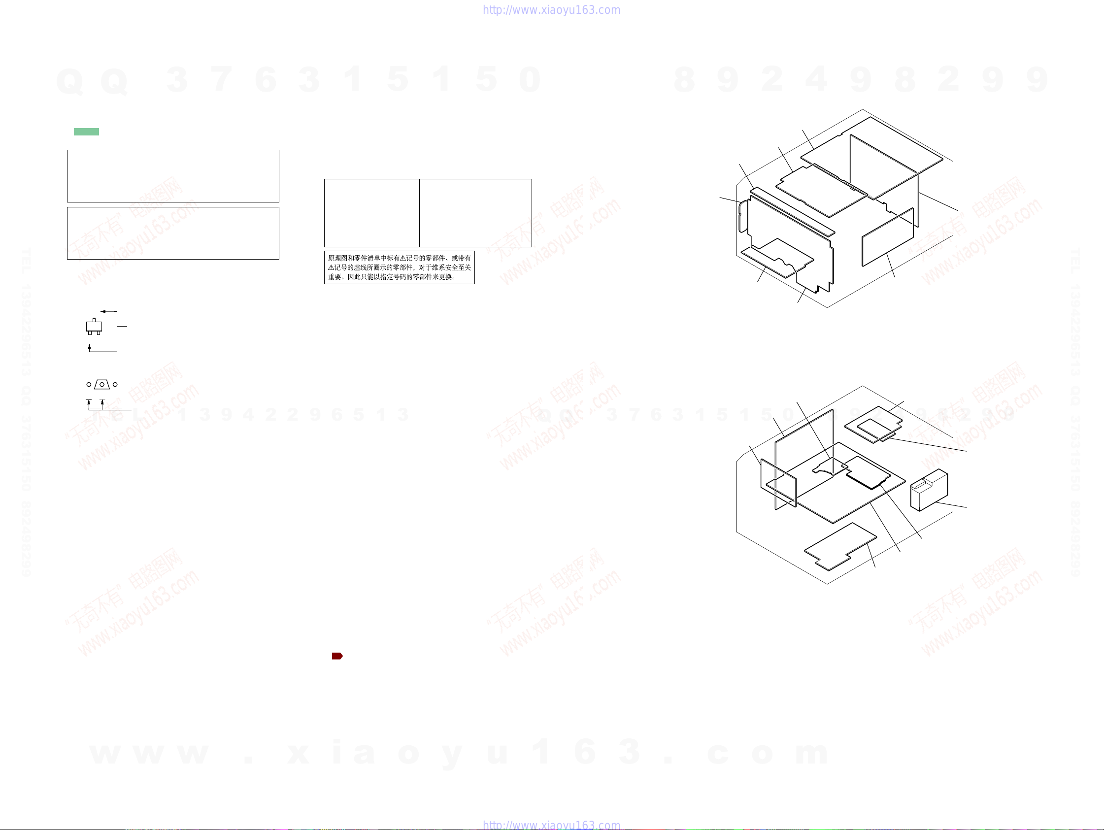
3
7
9
4
.
6
2
3
2
x
9
Q
Note on Printed Wiring Board:
• X : parts extracted from the component side.
• Y : parts extracted from the conductor side.
• f : internal component.
• : Pattern from the side which enables seeing.
(The other layers' patterns are not indicated.)
TEL 13942296513 QQ 376315150 892498299
• DMB15 board is multi-layer printed board.
• Indication of transistor
Q
Caution:
Pattern face side: Parts on the pattern face side seen from
(Conductor Side) the pattern face are indicated.
Parts face side: Parts on the parts face side seen from
(Component Side) the parts face are indicated.
Caution:
Pattern face side: Parts on the pattern face side seen from
(Side B) the pattern face are indicated.
Parts face side: Parts on the parts face side seen from
(Side A) the parts face are indicated.
However, the patterns of intermediate layers have not been
included in diagrams.
C
Q
B
E
B
T
w
These are omitted.
Q
CE
E
These are omitted.
L
w
3
1
w
1
Note on Schematic Diagram:
• All capacitors are in µF unless otherwise noted. (p: pF)
50 WV or less are not indicated except for electrolytics
and tantalums.
• All resistors are in Ω and 1/
specified.
• f : internal component.
• 2 : nonflammable resistor.
• C : panel designation.
Note:
The components identified by mark 0 or dotted
line with mark 0 are critical for safety.
Replace only with part
number specified.
• A : B+ Line.
• B : B– Line.
• Voltages and waveforms are dc with respect to ground
under no-signal (detuned) conditions.
– DMB15/VIDEO Boards –
no mark : DVD PLAY
– USB Board –
no mark : USB
– BT Board –
no mark : BLUETOOTH
– XM Board –
no mark : XM
– Other Boards –
no mark : TUNER (FM/AM)
6
(): DVD PLAY
{ }: BLUETOOTH
[]: XM
〈〈 〉〉 : SIRIUS
∗ : Impossible to measure
• Voltages are taken with a VOM (Input impedance 10 MΩ).
Voltage variations may be noted due to normal production tolerances.
• Waveforms are taken with a oscilloscope.
Voltage variations may be noted due to normal production tolerances.
• Circled numbers refer to waveforms.
• Signal path.
J : CD PLAY
c : DVD PLAY
I : DIGITAL OUT
F : AUDIO
L : VIDEO
E : Y
a : CHROMA
r : COMPONENT VIDEO
f : TUNER (FM/AM)
d : USB
E : BLUETOOTH IN
j : BLUETOOTH OUT
O : SIRIUS
h : AUDIO IN
N : MIC
• Abbreviation
AUS: Australian model
CH : Chinese model
CND : Canadian model
KR : Korean model
RU : Russian model
SP : Singapore model
TH : Thai model
i
TW : T aiw an model
5
: XM
a
1
5
3
o
1
4
W or less unless otherwise
Note:
Les composants identifiés par
une marque 0 sont critiques
pour la sécurité.
Ne les remplacer que par une
pièce portant le numéro
spécifié.
y
5
u
0
1
Q
Q
• Circuit Boards Location• Note For Printed Wiring Boards and Schematic Diagrams
• Circuit Boards Location
6
7
3
6
3
8
TOP-KEY board
ANT board
(DH5BT/DH7BT)
1
3
HP-AMP board
.
c
9
AMP board
JACK board
MS-214 board
DMB15 board
1
5
2
MAIN board
PANEL board
0
5
o
4
m
8
9
9
8
BT board
(DH5BT/DH7BT)
XM board
(DH7BT)
4
2
POWER board
USB board
(DH3/DH5BT)
HCD-DH3/DH5BT/DH7BT
Ver. 1.2
2
8
9
VIDEO board
9
POWER HT board
9
2
SP board
TUNER (FM/AM)
9
9
TEL 13942296513 QQ 376315150 892498299
HCD-DH3/DH5BT/DH7BT
2727
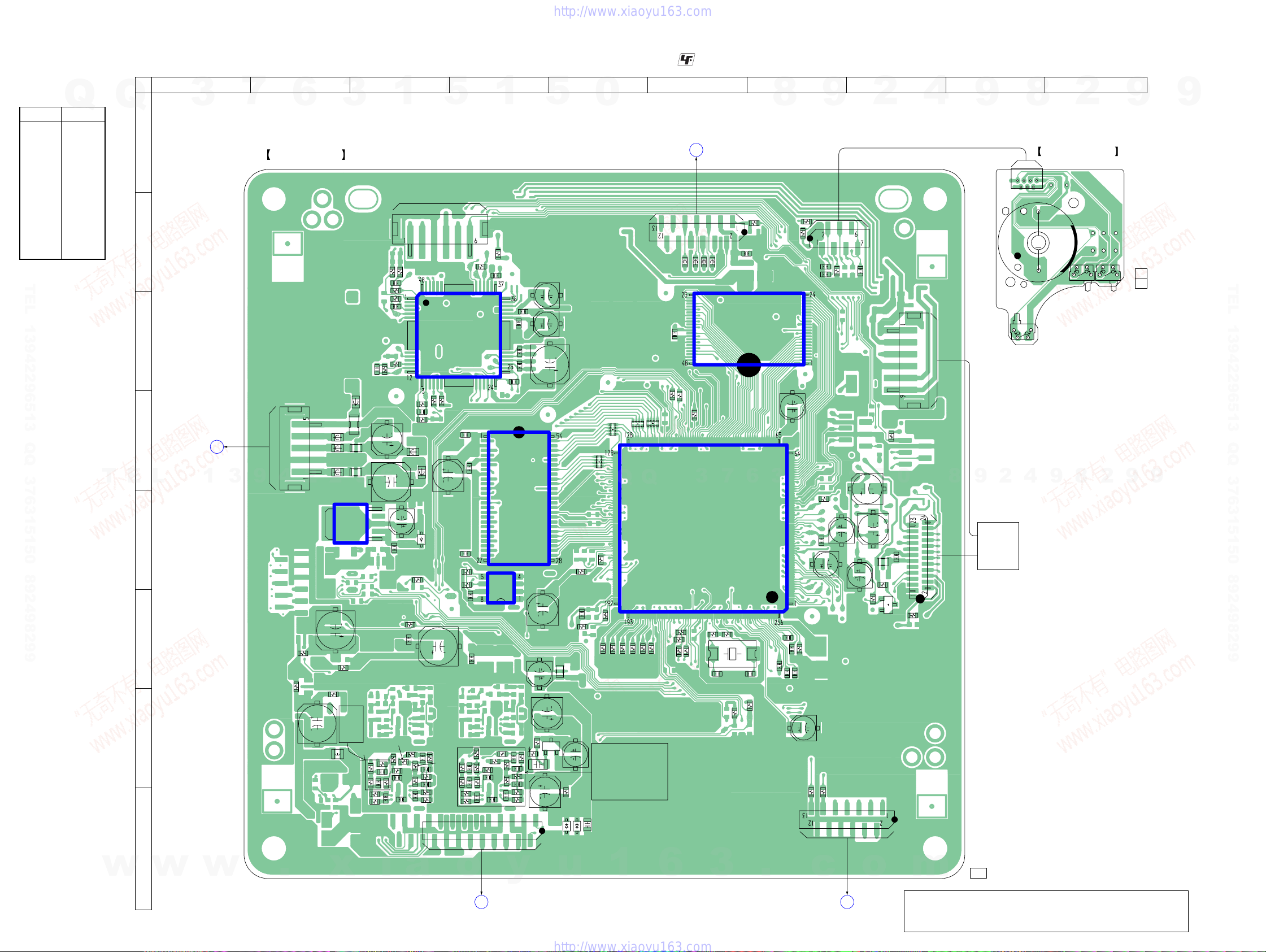
HCD-DH3/DH5BT/DH7BT
Ver. 1.2
6-6. PRINTED WIRING BOARDS – SERVO Section (1/2) –
• Semiconductor
Location
Ref. No. Location
D1001 E-3
D3501 H-5
D3502 H-5
IC101 C-7
IC102 E-6
IC103 E-4
IC104 E-4
IC106 E-3
IC201 C-4
Q103 F-8
Q3801 G-5
Q
Q
A
B
TEL 13942296513 QQ 376315150 892498299
1 2 3 4 5 6 7 8 9 10
3
7
DMB15 BOARD
6
3
(SIDE A)
R209
R215
C
R210
C208
FL402
9
R3716
R3717
R3718
R216
C403
C402
6
5
1
C189
R3714
C3714
T
E
FB405
FB401
FB403
FB402
2
FL403
FL401
D
L
B
POWER HT BOARD
CN205
(Page 50)
1
3
9
4
CN401
2
IC106
E
C307
F
G
R3801
R319
R3802
C3801
L3602
R3651
R3712
C3711
R3711
R3713
C3712
H
1
C205
R214
C206
C210
FB406
5
R3653
C305
R3722
R3721
C3713
C3701
R208
R3715
R3726
C3724
R224
R219
FB404
C187
D1001
5
(FOR CHECK)
CN105
R227
C190
1
C306
R3723
C3721
R3724
C3722
R3725
C3723
R3727
R3728
19
18
• See page 27 for Circuit Boards Location. :Uses unleaded solder.
IC201
R228
C179
3
C181
R191
R193
C180
C167
C302
R233
CN302
1
R107
C215
C223
IC104
IC103
C224
R3804
C219
C221
C222
R3803
2
C178
1
5
C220
C218
C217
C177
C3804
Q3801
C3803
FL107
E
C3802
C170
R1101
C3805
R3805
D3501
RB108
R1105
D3502
0
RB107
R1108
R1553
R189
C3771
R3771
R3773
C3772
R3777
R3778
C308
Q
R190
R3772
R3774
R3776
C3774
R192
R3782
R3775
C3773
C3707
RB113
R195
R3781
RB112
Q
R197
R3784
R3786
C3784
R1102
C3782
R3785
C3783
R3787
R3788
R161
R1549
R1550
R155
C3781
R3783
C102
A
CN106
FB114
FB115
R1557
R152
3
IC102
R153
MAIN BOARD
CN301
(Page 39)
FB113
FB112
7
R1168
R142
X101
C153
R1543
1545
R
C108
IC101
6
C152
R1559
8
R2502
R2501
C129
3
C133
C132
C138
C137
R4706
1
C135
C150
C225
C226
R234
R136
9
5
C116
C117
CN202
R4705
C119
CN301
R243
1
C118
R117
C2501
C105
2
5
C112
FL101
E
R116
Q103
R101
C101
0
CN201
CN101
4
R1129
8
9
9
OPTICAL
PICK-UP
BLOCK
(KHM-313CAB)
(LOADING)
2
8
MS-214 BOARD
71
6
2
CN001
M001
M
S002
(CHUCKING)
4
S002
9
2
S001
S001
(DISC IN/OUT)
8
S003
S003
(TRIGGER)
2
9
11
(11)
1-862-780-
9
9
TEL 13942296513 QQ 376315150 892498299
9
w
w
HCD-DH3/DH5BT/DH7BT
w
.
x
i
a
o
D
y
MAIN BOARD
CN302
u
(Page 39)
1
2828
6
3
.
c
VIDEO BOARD
C
(Page 34)
o
CN501
1-869-463-
m
Note: New part of EEPROM (IC103) on the DMB15 board cannot be
used. Therefore, if the mounted DMB15 board is replaced, exchange new EEPROM with that used before the replacement.
11, 21
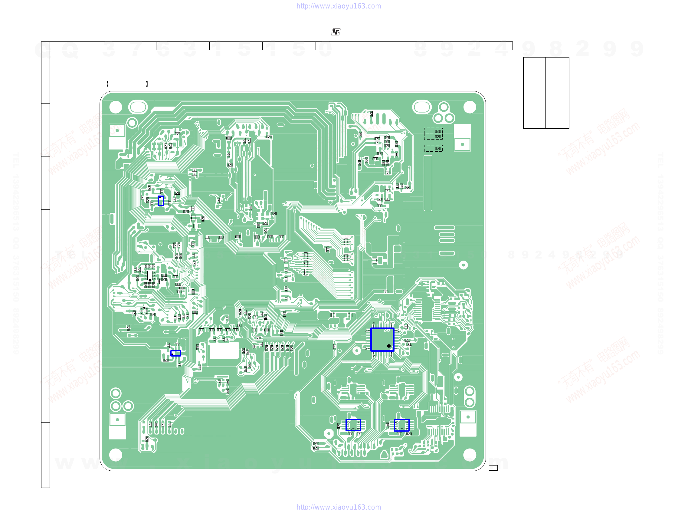
HCD-DH3/DH5BT/DH7BT
Ver. 1.2
6-7. PRINTED WIRING BOARD – SERVO Section (2/2) –
1 2 3 4 5 6 7 8 9
Q
Q
3
7
6
3
1
A
DMB15 BOARD
B
(SIDE B)
R237
R239
R2505
TEL 13942296513 QQ 376315150 892498299
R106
R105
C
R246
D
T
E
L
1
3
C106
9
R109
R110
1E
2B
2C
E
Q101
1S
1G
2D
R108
R114
F
R247
R118
R115
2S
R187
4
R120
Q102
R112
1D
2G
R111
1
3
IC105
C184
R121
1C
1B
2E
R124
R113
R126
C113
R123
C193
C188
2
5
4
R1126
R1161
C182
5
1
C196
R238
C126
C195
R236
2
C114
C120
R1133
R1554
R1109
C121
4
IC107
3
C122
C192
C115
C123
9
C124
R196
C131
C128
C127
C125
C139
R127
R138
FL105
C130
R169
C136
6
C140
C147
• See page 27 for Circuit Boards Location. :Uses unleaded solder.
FB111
R1150
C144
5
C146
R104
C151
R1526
C109
C148
C149
1
R143
R1524
5
R1152
C155
3
C156
C154
R141
R1547
R146
R1540
R1151
R1503
C160
R1531
R1551
C159
R1548
C158
R151
R160
R1104
1
R1502
R164
R1504
C162
R1530
R1552
C161
R1103
R1120
R1546
R1121
C164
C176
C175
C174
C173
C172
R1122
C171
C163
R1123
5
R1125
R1124
RB111
RB103
RB104
0
C191
Q
FL106
R3501
RB105
RB106
Q
FL104
R232
R231
R230
R1110
R225
R223
R222
C213
C209
R206
R205
3
FL108
IC301
C214
R220
R226
C212
R1134
C211
R221
R213
7
8
(DH3: CH, SP, KR, TH/DH5BT: CH, SP, TW, KR, TH)
C233
R212
R207
C203
R204
3
6
R3652
R314
C301
9
R5017
R5016
(DH3: AUS/DH5BT: AEP, RU, AUS)
R5014
(DH5BT: CND/DH7BT)
5
1
1
2
5
0
4
• Semiconductor
Location
9
Ref. No. Location
D3601 H-8
D3602 G-7
IC105 C-3
IC107 F-3
IC301 F-7
IC3711 H-7
IC3771 H-6
Q101 E-2
Q102 E-2
9
8
2
8
4
9
2
8
2
9
9
9
TEL 13942296513 QQ 376315150 892498299
9
G
H
w
HCD-DH3/DH5BT/DH7BT
w
w
.
R4701
R321
R4702
R4703
R4704
x
i
a
R1542
o
y
IC3771
R3789
C3708
R3779
6
u
R3502
R3503
1
2929
R3729
3
IC3711
R3719
C3702
.
c
1-869-463-
o
11, 21
m

HCD-DH3/DH5BT/DH7BT
Ver. 1.2
6-8. SCHEMATIC DIAGRAM – SERVO Section (1/4) –
Q
Q
3
7
6
• See page 57 for IC Block Diagrams.
3
1
(1/4)
RF+3.3V
RF1.8
(Page 32)
REG01
REG02
(Page 31)
TEL 13942296513 QQ 376315150 892498299
T
E
L
(Page 40)
(FOR CHECK)
w
w
CN101
24P
GND (LD)
LD (650)
NC
NC
PD
LD (780)
VR (650)
VR (780)
NC
VOE/E+G
VCC
VC
GND (PDIC)
VOF/F+H
VOB/B
VOA/A
RF
(LO:DVD.HI:CD)MSW
VOD/D
VOC/C
TRK-
TRK+
FCS+
FCS-
1
CN106
13P
OCSW1
SYSRST
3.3VMNT
XIFCS
IFBSY
IFSDI
IFSDO
M-REQ
IFCK
DGND
MIC
NC
KRMOD
CN105
6P
RFMON
V2REFO
+3.3V
GND
RXD
TXD
w
3
9
C178
47
4V
4
.
R1545
FL107
2
0
DVD_LD
PD
CD_LD
VOE
C101
R101
100
R1546
3.3k
C109
0.01
2
C108
0.001
0.001
R1502
R1110
x
0
2.7k
RFMON
OCSW1
KRMOD
RFMON
V2REFO
MREQ
TRK+
FCS+
VOB
VOA
VOD
VOC
TRK-
FCS-
RXD
TXD
VC
VOF
RF
9
MIC
6
i
IOP
LDO2
DVD_LD
CD_LD
FL101
R108
1M
Q101-1
CD ON SWITCH
Q101-2
DVD ON SWITCH
5
1
R107
10k
R114 R1129
100k 100k
a
5
SS
-1 -2
R111
100
3
C105
R110
47k
6.3V
R109
0
C106
0.01
FB111
FB112
FB113
FB114
FB115
o
1
R126
0
Q101
UM6K1N-TN
Q103
DTC124EKA-
T146
INVERTER
R112 R113 R115
22 22 22
47
C192
0.01
R116
1k
AUTOMATIC POWER
CONTROL(FOR CD)
AUTOMATIC POWER
CONTROL(FOR DVD)
R1150
R1152
R1151
y
Q102-1
Q102-2
C193
0.22
R117
47k
3.3k
3.3k
3.3k
5
MSW
R118 R120 R121
22 22 22
-2-1
PRST
XIFCS
IFBSY
IFSDI
IFSDO
IFCK
u
BR24L64F-WE2
A0
A1
A2
GND
Q102
QST8TR
C113
0.01
0
+3.3V REGULATOR
IC107
TK11133CSCL-G
CONT
GND
NOISE
EEPROM
IC103
VCC
WP
SCL
SDA
C112
47
6.3V
R105
10k
R106
10k
VIN
VOUT
Q
R123
0
LDO1
A16
A15
A14
A13
A12
A11
A10
A9
A20
A21
A19
A18
A8
A7
A6
A5
A4
A3
A2
1
FCS-
FCS+
TRK+
TRK-
IOP
OCSW1
RF
VOA
VOB
VOC
VOD
VOE
VOF
PD
MSW
VC
LDO2
PRST
LDO1
TXD
RXD
IFBSY
SDA
SCL
IDSDI
XIFCS
IFCK
IFSDO
MREQ
MIC
KRMOD
V2REFO
9
D1001
RB501V-40TE-17
C189
0.33
2
8
C184
0.01
R187
0
C188
0.22
C187
47
4V
2
V2REFO
A11
A12
A6
A5
A4
A9
A10
A7
A8
SW+3.3V
SW+5V
A1
A2
A3
9
FCS-
FCS+
TRK+
TRK-
IOP
OCSW1
RF
VOA
VOB
VOC
VOD
VOE
VOF
PD
MSW
VC
LDO2
PRST
LDO1
TXD
RXD
IFBSY
SDA
SCL
IFSDI
XIFCS
IFCK
IFSDO
MREQ
MIC
KRMOD
9
(Page 32)
GND
(Page 32)
9
(Page
31)
TEL 13942296513 QQ 376315150 892498299
(Page
32)
9
(Page 31)
0
A17
A0
4
C190
47
6.3V
R1133
R169
C182
0.22
m
47
47
DQM0
RD7
RD6
RD5
RD4
RD3
RD2
RD1
RD0
2
+3.3V REGULATOR
TK11133CSCL-G
VOUT
VIN
+1.8V REGULATOR
PQ018EN01ZPH
NC
GND
RCS
RAS
CAS
RWE
IC106
R1134
IC105
VOUT
CONT
8
RA3
RA2
RA1
RA0
RA10
BA1
BA0
4
NOISE
GND
CONT
VIN
0
9
C181
0.1
RB106
C180
0.1
RB105
C179
0.1
FL108
9
8
0
10k
SD-RAM
IC104
A2V64S40CTP-G75
VSS
A4
A5
A6
A7
A8
A9
A11
NC
CKE
CLK
UDQM
NC
LDQM
VSS
DQ8
VDDQ
DQ9
DQ10
VSSQ
VDDQ
DQ11
DQ12
VDDQ
DQ13
DQ14
VSSQ
VDDQ
DQ15
VSS
1
C102
o
2
VDDB
A3
A2
A1
A0
A10
BA1
BA0
/CS
/RAS
/CAS
/WE
VDD
DQ7
VSSQ
DQ6
DQ5
DQ4
DQ3
VSSQ
DQ2
DQ1
DQ0
VDD
5
1
XROMCS
XWR
HD7
HD6
HD5
HD4
HD3
HD2
HD1
HD0
XRD
A1
1
9
5
c
8
RA4
RA5
RA6
RA7
RA8
C195
0.22
C167
R191
0.01
1k
R193
1k
SDA
SCL
Q
R124
47k
R104
0
3
6
RA9
RA11
DRCKE
DRCLK
DQM1
C191
0.1
RD8
RD9
RD10
RD11
RD12
RD13
RD14
RD15
3
6
7
FLASH ROM
A15
A14
A13
A12
A11
A10
A9
A8
A19
A20
WE
RESET
N.C.
N.C.
RY/BY
A18
A17
A7
A6
A5
A4
A3
A2
A1
IC101
A16
BYTE
VSS
A-1
DQ7
DQ14
DQ6
DQ13
DQ5
DQ12
DQ4
VCC
DQ11
DQ3
DQ10
DQ2
DQ9
DQ1
DQ8
DQ0
OE
VSS
CE
A0
.
MX29LV320CBTC70-SBA3-0701UC
(DH5BT:CND/DH7BT)
MX29LV320CBTC70-SBA3-0701CE
(DH3:AUS/DH5BT:AEP,RU,AUS)
MX29LV320CBTC70-SBA3-0701GA
(DH3:CH,SP,KR,TH/DH5BT:CH,SP,TW,KR,TH)
3
HCD-DH3/DH5BT/DH7BT
3030
Note: New part of EEPROM (IC103) on the DMB15 board cannot be
used. Therefore, if the mounted DMB15 board is replaced, exchange new EEPROM with that used before the replacement.
 Loading...