

Sony HCD-CV40 Service Manual
HCD-CV40
SERVICE MANUAL
Ver 1.0 2002. 07
This set is the tuner, deck, VIDEO CD/CD play er
and amplifier section in CHC-CV40.
Model Name Using Similar Mechanism NEW
CD
SECTION
TAPE DECK
SECTION
CD Mechanism Type CDM63E
Base Unit Type BU-30BD62
Optical Pick-up Type A-MAX.3
Model Name Using Similar Mechanism HCD-TB20
Tape T ransport Mechanism T ype CMAL1Z222A
E Model
Amplifier section
Measured at AC 120/220/240 V, 50/60 Hz:
DIN power output (Rated):40 + 40 watts
Continuous RMS power output (Reference):
Inputs
MD (VIDEO) IN (phono jacks):
Outputs
PHONES (stereo minijack):
SPEAKER: accepts impedance of 6 to
VIDEO CD/CD player section
System Compact disc and digital
Laser Semiconductor laser
Frequency response 2 Hz – 20 kHz (±0.5 dB)
VIDEO OUT (phono jack) 1 Vp-p, 75 ohms
(6 ohms at 1 kHz, DIN)
50 + 50 watts
(6 ohms at 1 kHz, 10%
THD)
voltage 450 mV (250
mV), impedance 47
kilohms
accepts headphones of
8 ohms or more.
16 ohms.
audio system
(λ=795 nm)
Emission duration:
continuous
SPECIFICATIONS
Tape deck section
Recording system 4-track 2-channel stereo
Frequency response 50 – 13,000 Hz (±3 dB),
Wow and flutter ±0.15% W. Peak (IEC)
Tuner section
FM stereo, FM/AM superheterodyne tuner
FM tuner section
Tuning range 87.5 – 108.0 MHz
Antenna FM lead antenna
Antenna terminals 75 ohms unbalanced
Intermediate frequency 10.7 MHz
AM tuner section
Tuning range 531 – 1,602 kHz
Antenna AM loop antenna
Intermediate frequency 450 kHz
using Sony TYPE I
cassettes
0.1% W. RMS (NAB)
±0.2% W. Peak (DIN)
(50 kHz step)
(with the interval set at
9 kHz)
530 – 1,710 kHz
(with the interval set at
10 kHz)
External antenna terminals
General
Power requirements 120 V, 220 V, 230 –
Power consumption 120 watts
Dimensions (w/h/d) incl. projecting parts and controls
Amplifier/Tuner/Tape/CD section:
Speaker Approx. 205 × 285 ×
Mass
Amplifier/Tuner/Tape/CD section:
Speakers Approx. 3.6 kg net per
Supplied accessories Remote (1)
Design and specifications are subject to change
without notice.
240 V AC, 50/60 Hz
Adjustable with voltage
selector
Approx. 215 × 285 ×
386 mm
240 mm
Approx. 7.8 kg
speaker
R6 (size AA) batteries (2)
AM loop antenna (1)
FM lead antenna (1)
Speaker pads (8)
Video connecting cable
(1)
9-874-079-01
2002G1600-1
© 2002.07
COMPACT Hi-Fi COMPONENT SYSTEM
Sony Corporation
Home Audio Company
Published by Sony Engineering Corporation

HCD-CV40
TABLE OF CONTENTS
1. SERVICING NOTES ······················································· 3
2. GENERAL ·········································································· 5
3. DISASSEMBLY ································································ 7
3-1. Side Panel ····································································· 8
3-2. Top Panel ······································································ 8
3-3. Cassette Mechanism Deck, TC Board ·························· 9
3-4. Front Panel····································································9
3-5. FRONT INPUT Board, CD Lid·································· 10
3-6. MIC Board, PANEL Board·········································10
3-7. DISPLAY Board ························································· 11
3-8. VOL Board ································································· 11
3-9. VOL SEL Board, Back Panel ····································· 12
3-10. MAIN Board, VIDEO Board······································ 12
3-11. SUB POWER Board, Power Transformer (T901) ······ 13
3-12. THERMAL Board, AMP Board·································13
3-13. CD Mechanism Deck (CDM63E) ······························ 14
3-14. CD Base Unit (BU-30BD62)······································15
3-15. DRIVER Board··························································· 16
3-16. Fitting Base (Stabilizer) Assy, Tray Assy ··················· 16
3-17. TRAY SENSOR Board ··············································· 17
3-18. Slider (Loading), Gear (Slider)···································17
3-19. Stocker Assy ······························································· 18
3-20. DISC SENSOR Board ················································ 18
3-21. IN OUT SW Board ····················································· 19
3-22. Motor Assy (M721), MOTOR Board ························· 20
4. TEST MODE···································································· 21
5. MECHANICAL ADJUSTMENTS ····························· 23
6. ELECTRICAL ADJUSTMENTS ······························· 23
7. DIAGRAMS
7-1. Circuit Boards Location·············································· 28
7-2. Block Diagrams ·························································· 29
7-3. Printed Wiring Board – BD Board –·························· 31
7-4. Schematic Diagram – BD Board – ···························· 32
7-5. Printed Wiring Board – VIDEO Board (Side A) – ····33
7-6. Printed Wiring Board – VIDEO Board (Side B) – ···· 34
7-7. Schematic Diagram – VIDEO Board (1/2) –············· 35
7-8. Schematic Diagram – VIDEO Board (2/2) –············· 36
7-9. Printed Wiring Board – MAIN Board – ····················37
7-10. Schematic Diagram – MAIN Board (1/3) – ·············· 38
7-11. Schematic Diagram – MAIN Board (2/3) – ·············· 39
7-12. Schematic Diagram – MAIN Board (3/3) – ·············· 40
7-13. Printed Wiring Boards – Driver Section – ················· 41
7-14. Schematic Diagram – Driver Section – ····················· 42
7-15. Printed Wiring Board – TC Board – ·························· 43
7-16. Schematic Diagram – TC Board –·····························44
7-17. Printed Wiring Boards – AMP Section –··················· 45
7-18. Schematic Diagram – AMP Section – ······················· 46
7-19. Printed Wiring Boards – Panel Section –··················· 47
7-20. Schematic Diagram – Panel Section –·······················48
7-21. Printed Wiring Boards – Power Section – ················· 49
7-22. Schematic Diagram – Power Section –······················ 50
7-23. Printed Wiring Board – MIC Board –························ 51
7-24. Schematic Diagram – MIC Board – ··························51
7-25. IC Pin Function Description ······································· 56
8. EXPLODED VIEWS
8-1. Side Panel, Back Panel Section ·································· 58
8-2. Front Panel Section·····················································59
8-3. Chassis Section ··························································· 60
8-4. CD Mechanism Deck Section -1 ································ 61
8-5. CD Mechanism Deck Section -2 ································ 62
8-6. Base Unit Section (BU-30BD62) ······························· 63
9. ELECTRICAL PARTS LIST······································· 64
Unleaded solder
Boards requiring use of unleaded solder are printed with the leadfree mark (LF) indicating the solder contains no lead.
(Caution: Some printed circuit boards may not come printed with
the lead free mark due to their particular size.)
: LEAD FREE MARK
Unleaded solder has the following characteristics.
• Unleaded solder melts at a temperature about 40°C higher than
ordinary solder.
Ordinary soldering irons can be used but the iron tip has to be
applied to the solder joint for a slightly longer time.
Soldering irons using a temperature regulator should be set to
about 350°C.
Caution: The printed pattern (copper foil) may peel away if the
heated tip is applied for too long, so be careful!
• Strong viscosity
Unleaded solder is more viscous (sticky, less prone to flow) than
ordinary solder so use caution not to let solder bridges occur such
as on IC pins, etc.
• Usable with ordinary solder
It is best to use only unleaded solder but unleaded solder may
also be added to ordinary solder.
2
SECTION 1
SERVICING NOTES
HCD-CV40
NOTES ON HANDLING THE OPTICAL PICK-UP
BLOCK OR BASE UNIT
The laser diode in the optical pick-up block may suffer electrostatic
break-down because of the potential difference generated by the
charged electrostatic load, etc. on clothing and the human body.
During repair, pay attention to electrostatic break-down and also
use the procedure in the printed matter which is included in the
repair parts.
The flexible board is easily damaged and should be handled with
care.
NOTES ON LASER DIODE EMISSION CHECK
The laser beam on this model is concentrated so as to be focused on
the disc reflective surface by the objective lens in the optical pickup block. Therefore, when checking the laser diode emission,
observe from more than 30 cm away from the objective lens.
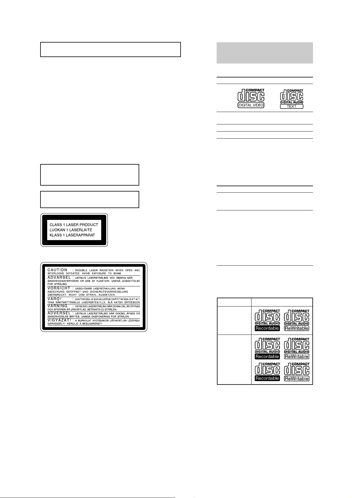
Laser component in this product is capable
of emitting radiation exceeding the limit for
Class 1.
Do not install the appliance in a confined
space, such as a bookcase or built-in cabinet.
This appliance is classified as
a CLASS 1 LASER product.
The label is located on the rear
exterior.
The following caution label is located inside the apparatus.
This system can play the
following discs
VIDEO CDs Audio CDs
Disc logo
Contents Audio + Video Audio
Disc size 12 cm/8 cm 12 cm/8 cm
Play time 74 min./20 min. 74 min./20 min.
Note on VIDEO CDs
This system conforms to VIDEO CDs without PBC
functions (Ver. 1.1) and VIDEO CDs with PBC
functions (Ver. 2.0) of VIDEO CD standards. You
can enjoy two kinds of playback according to the disc
type.
Disc type
VIDEO CDs without
PBC functions
(Ver. 1.1 discs)
VIDEO CDs with
PBC functions
(Ver. 2.0 discs)
(moving pictures)
You can
Enjoy video playback
(moving pictures) as
well as audio CDs.
Play interactive software
using menu screens
displayed on the TV screen
(menu playback), in addition
to the video playback
function of VIDEO CDs
without PBC functions.
Moreover, you can play high
or standard quality still
picture.
Notes on chip component replacement
•Never reuse a disconnected chip component.
• Notice that the minus side of a tantalum capacitor may be
damaged by heat.
Flexible Circuit Board Repairing
•Keep the temperature of soldering iron around 270˚C
during repairing.
• Do not touch the soldering iron on the same conductor of the
circuit board (within 3 times).
• Be careful not to apply force on the conductor when soldering
or unsoldering.
SAFETY-RELATED COMPONENT WARNING!!
COMPONENTS IDENTIFIED BY MARK 0 OR DOTTED LINE WITH
MARK 0 ON THE SCHEMATIC DIAGRAMS AND IN THE PARTS
LIST ARE CRITICAL TO SAFE OPERATION. REPLACE THESE
COMPONENTS WITH SONY PARTS WHOSE PART NUMBERS
APPEAR AS SHOWN IN THIS MANUAL OR IN SUPPLEMENTS
PUBLISHED BY SONY .
PBC = Playback Control
Notes on CD-R and CD-RW discs
This system can play the following discs:
Type of discs Label on the disc
Audio CD
MP3 files
• Discs recorded on CD-R/CD-RW drives may not be
played back because of scratches, dirt, recording
condition or the drive’s characteristics.
• You cannot play a CD-R/CD-RW that is not
finalized.
• You cannot play a CD-R/CD-RW that is recorded
in Multi Session.
3

HCD-CV40
Service position of the CD mechanism deck
BD board
VIDEO board
flat cable (1-823-974-11)
Service position of the TAPE cassette mechanism deck
Jig cord : J-2501-082-A
MAIN board
TC Deck section
4
SECTION 2
GENERAL
HCD-CV40
This section is extracted
from instruction manual.
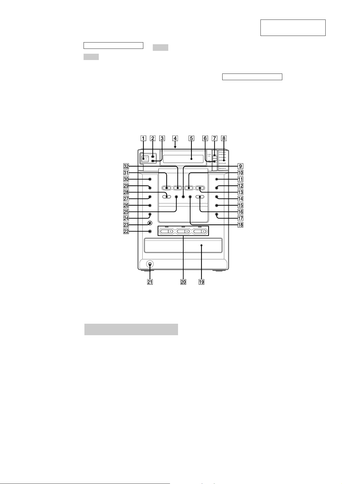
ALPHABETICAL ORDER
A – G
CD disc tray ql (10)
CD SYNC wl (24)
CD NX ea (11, 14, 16)
DBFB wf (26)
DIMMER 2 (31)
DISC 1 – 3 w; (11, 14)
DISC 1 – 3 Z w; (8, 10)
DISPLAY 3 (31)
Display window 5
EDIT wj (25)
ENTER qf (10, 15, 21, 25, 27)
EQ EDIT qk (27)
FUNCTION qh (10, 14, 15, 17)
GROOVE 9 (26)
M – Z
MD (VIDEO) 0 (35)
MIC jack ws (29)
MIC LEVEL wd (29)
MUSIC MENU wg (27)
PHONES jack wa
PLAY MODE/TUNING MODE
qg (11, 14, 15, 20)
REC PAUSE/START e; (24)
Remote sensor qa
REPEAT/FM MODE qj (12, 14,
18, 22)
SURROUND wh (26)
Tape deck lid 4 (23)
TAPE nN qd (23, 24)
TUNER/BAND es (20, 22)
TUNER MEMORY/DIRECTION
qs (21, 23)
VOL 8
BUTTON DESCRIPTIONS
?/1 1
+/M L 7
x wk
l –/m 6
Setting the clock
1
Turn on the system.
2
Press CLOCK/TIMER SET on the
remote.
3
Press R or r on the remote to set the
hour.
4
Press ENTER.
5
Press R or r on the remote to set the
minute.
6
Press ENTER.
The clock starts working.
If you make a mistake
Press T or t on the remote repeatedly until
the incorrect item flashes, then set it again.
To adjust the clock
1
Press CLOCK/TIMER SET on the remote.
2
Press R or r on the remote to select
“CLOCK SET?”, then press ENTER.
3
Do the same procedures as step 3 to 6
above.
Note
You cannot set the clock in the Power Saving Mode.
5

HCD-CV40
A – K
ALBUM +/– e; (17)
CD N wh (11, 14, 17)
CLEAR 6 (16)
CLOCK/TIMER SELECT ek
(26, 29)
CLOCK/TIMER SET 1
(10, 25, 28)
DBFB qj (26)
DIMMER ef (31)
DISC SKIP qf (11, 14)
DISPLAY ed (31)
ENTER wa (10, 15, 21, 25, 27)
FUNCTION wk (10, 14, 15, 17)
GROOVE ws (26)
KARAOKE PON/MPX wl (29)
KEY CONTROL #/2 ql (30)
M – Z
MD (VIDEO) wj (35)
MUSIC MENU +/– 9 (27)
NEXT wf (13)
Numeric buttons eg (12, 19)
ON SCREEN eh (32)
PICTURE EFFECT wd (12)
PLAY MODE es (11, 14)
PREV wf (13)
REPEAT ea (12, 14, 18)
RETURN O q; (13)
SELECT wh (13, 19)
SLEEP ej (28)
SPECIAL MENU 8 (19)
SURROUND qg (26)
TAPE nN qd (23, 24)
TUNER/BAND wg (20, 22)
TV CH +/– 5 (9)
TV VOL +/– 4 (9)
TV @/1 2 (9)
TV/VIDEO 7 (9)
VOL +/– qk
BUTTON DESCRIPTIONS
@/1 3
x qs
X qa
m/M qh
./> wf
R/r/T/t (cursor) w; (10, 12)
6

SECTION 3
DISASSEMBLY
• The equipment can be removed using the following procedure.
SET
SIDE PANEL
HCD-CV40
TOP PANEL
CASSETTE MECHANISM
DECK, TC BOARD
FRONT INPUT BOARD,
CD LID
• The dotted square with arrow ( ) prompts you to move to the next
job when all of the works within the dotted square ( )are completed.
FRONT PANEL
MIC BOARD,
PANEL BOARD
DISPLAY BOARD
VOL BOARD
VOL SEL BOARD,
BACK PANEL
MAIN BOARD,
VIDEO BOARD
CD MECHANISM
DECK (CDM63E)
CD BASE UNIT
(BU-30BD62)
FITTING BASE (STABILIZER) ASSY,
TRAY ASSY
SUB POWER BOARD,
POWER TRANSFORMER (T901)
THERMAL BOARD,
AMP BOARD
DRIVER BOARD
TRAY SENSOR BOARD
SLIDER(LOADING), GEAR (SLIDER)
STOCKER ASSY
DISC SENSOR BOARD
MOTOR ASSY (M721), MOTOR BOARD
IN OUT SW BOARD
7
HCD-CV40
)
Note : Follow the disassembly procedure in the numerical order given.
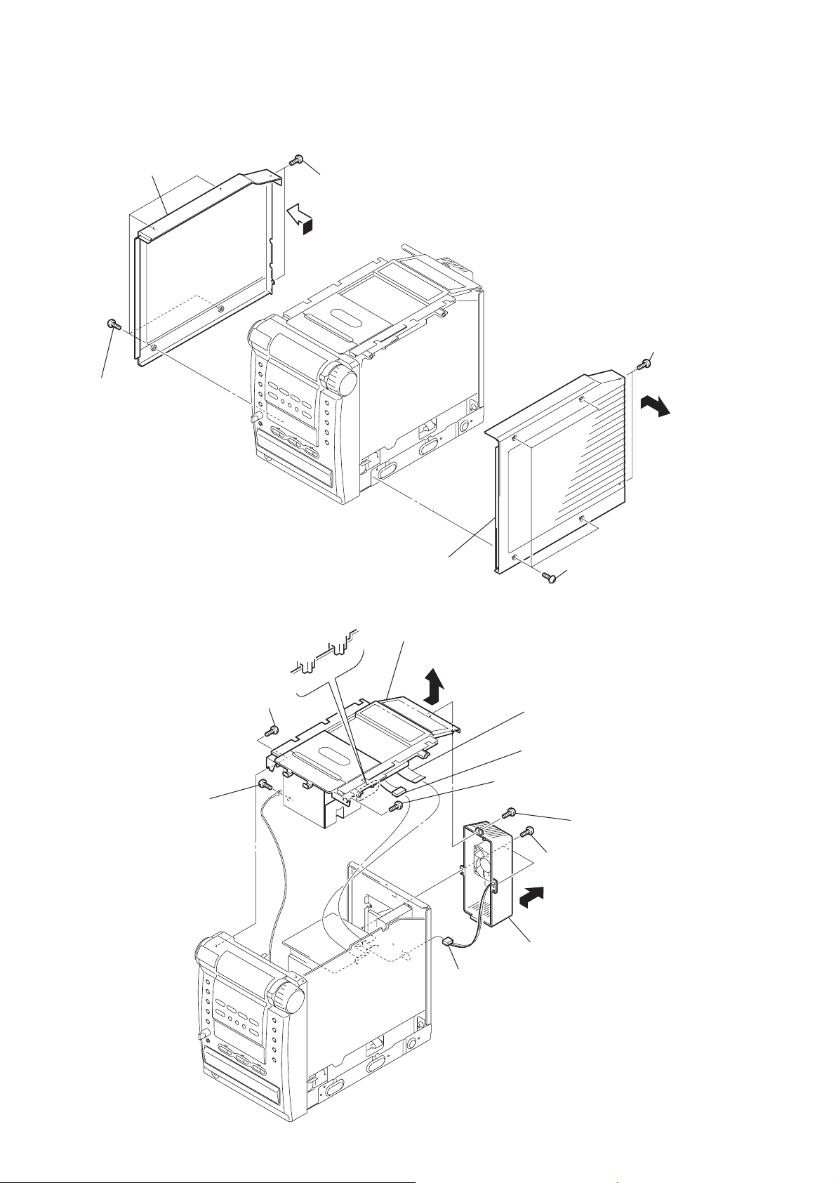
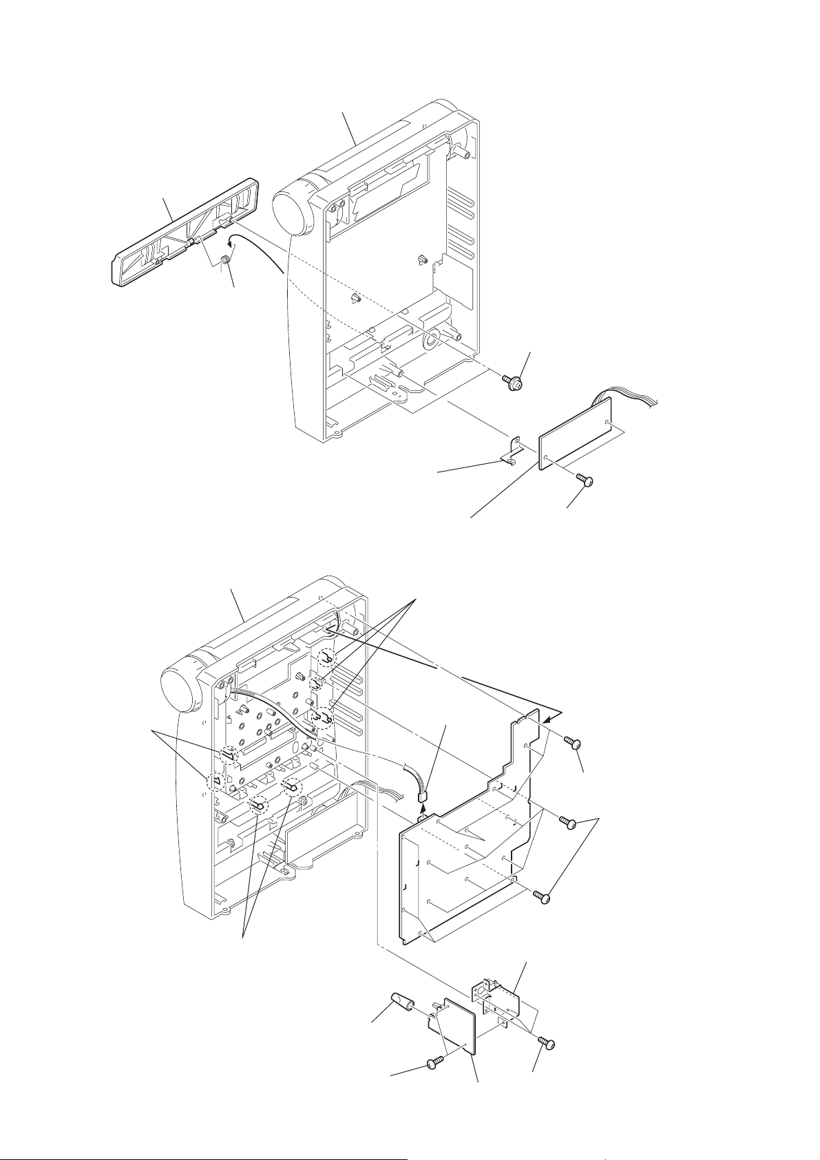
3-1. Side Panel
6
side panel (L)
(Remove in the direction
of the arrow)
5
four screws
(
CASE 3 TP2)
4
two
screws
(
+BVTP 3 × 8
)
1
two
screws
(
+BVTP 3 × 8
3-2. Top Panel
3
(
Note: Attach it so that it
s
crew
+BVTP 3 × 8
pressed down the
MAIN board.
4
s
crew
(
+BVTP 2.6 × 8
)
3
side panel (R)
(Remove in the direction
of the arrow)
7
top panel
(Remove in the direction
of the arrow)
6
)
9
connector
(CN904)
flat cable (9 core)
(CN321)
5
2
s
crew
(
+BVTP 2.6 × 8
2
four screws
(
CASE 3 TP2)
connector
(CN322)
)
1
screw
(
+BVTT 3 × 8
8
two screws
(
+BVTP 3 × 8
q;
Heat sink, cover
(Remove in the direction
of the arrow)
)
)
8

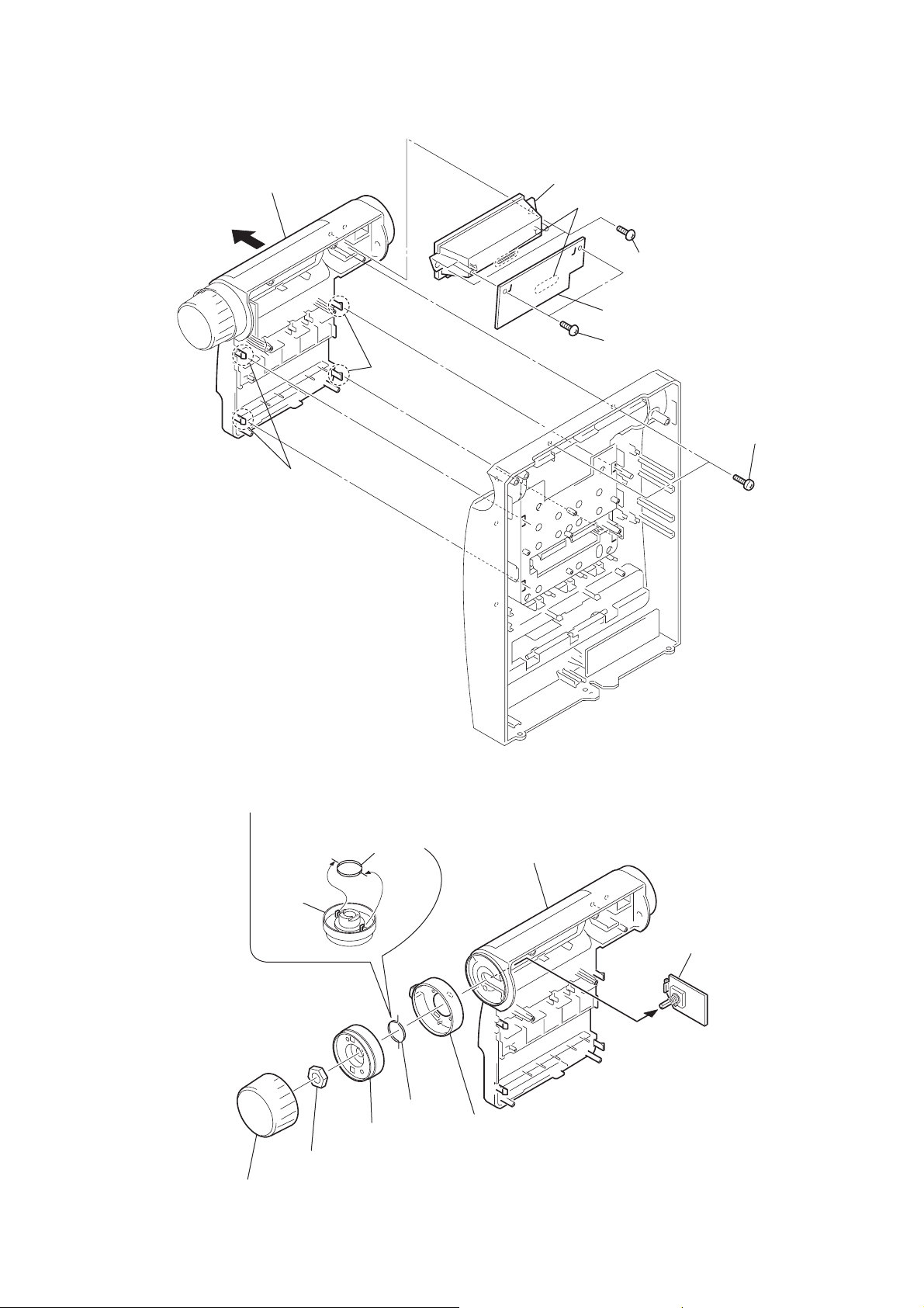
3-3. Cassette Mechanism Deck, TC Board
k
3
screw
(
+BVTP 2.6 × 8
5
screw
(
+BVTT 2.6 × 5
6
shield tc
(cassette mechanism)
1
two screws
(
+BVTP 2.6 × 8
)
)
HCD-CV40
qa
)
7
2
screw
(
+BVTP 2.6 × 8
flat cable (9 core)
cassette mechanism dec
)
3-4. Front Panel
0
TC board
8
front panel
4
connector
(CN341)
1
connector
(CN805)
8
(
5
screw
(
+BVTP 3 × 8
4
two screws
(
+BVTT 2.6 × 5
9
connector
three s
crews
+BVTP 3 × 8
6
screw
(
+BVTP 3 × 8
)
)
)
)
7
three
(
+BVTP 3 × 8
screws
2
connector
(CN402)
3
flat cable (17 core)
(CN401)
)
9
HCD-CV40
)
3-5. FRONT INPUT Board, CD Lid
5
CD
Lid
6
s
pring (CD)
front panel assy
3
ground
4
two
screws
+PTPWH 2.6 × 5
(
)
3-6. MIC Board, PANEL Board
front panel assy
9
two claws
2
FRONT INPUT board
8
four claws
qs
connector
(CN720)
1
two
screws
+BVTP 2.6 × 8
(
qa
PANEL board
(Remove in the direction
of the arrow)
6
five
(
)
screws
+BVTP 2.6 × 8
7
eleven
+BVTP 2.6 × 8
(
)
screws
10
0
two claws
3
two
(
+BVTP 3 × 8
2
mic knob
screws
4
mic bracket
)
5
MIC board
1
three
screws
+BVTP 2.6 × 8
(
)
3-7. DISPLAY Board
)
d
4
sub
panel
2
two claws
3
two claws
9
liquid crystal display panel
6
Remove ten solderings
5
two
screws
(
+BVTP 2.6 × 8
8
DISPLAY board
7
two
screws
(
+BVTP 2.6 × 8
)
)
1
two
screws
+BVTP 2.6 × 8
(
HCD-CV40
3-8. VOL Board
Note: daring reassembling
when flange.
flange
2
1
volume
knob
spring
3
nut
flange
4
spring
5
sub
shuttle
panel
6
VOL boar
11
HCD-CV40
t
)
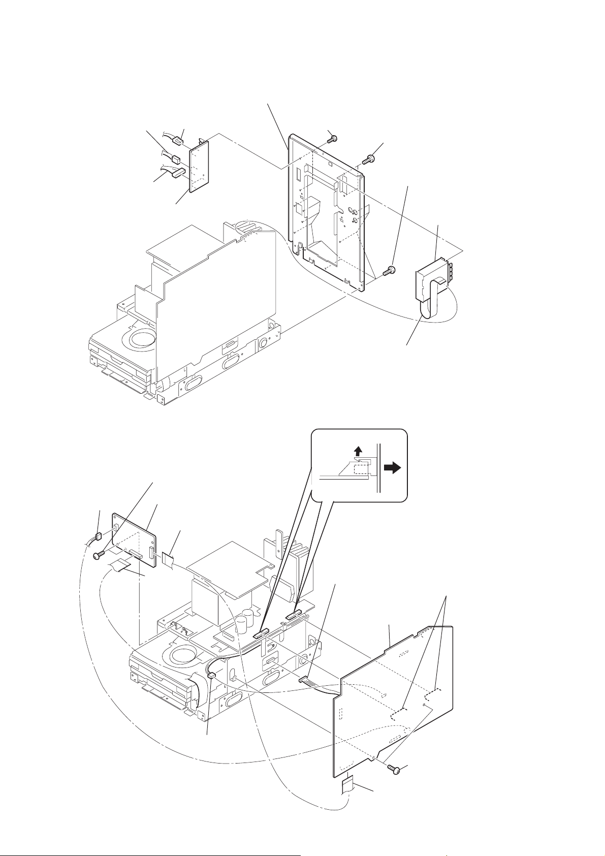
3-9. VOL SEL Board, Back Panel
5
connector
6
connector
(CN942)
7
connector
(CN941)
9
VOL SEL board
(CN943)
0
back panel
8
two screws
(
+BVTP 3 × 8
)
3
two screws
(
+BVTP 3 × 8
2
eleven screws
(
+BVTP 3 × 8
)
4
)
tuner uni
3-10. MAIN Board, VIDEO Board
8
two screws
(
+BVTP 3 × 8
5
connector
(CN301)
qa
VIDEO board
9
flat cable
(28 core)
(CN101)
)
q;
flat cable (19 core)
(CN201)
2
connector
(CN701)
1
(CN323)
MAIN board
7
MAIN board
flat cable
6
two connectors
(CN101, CN102
12
3
connector
(CN501)
1
two screws
(
4
flat cable (19 core)
(CN301)
+BVTP 3 × 8
)
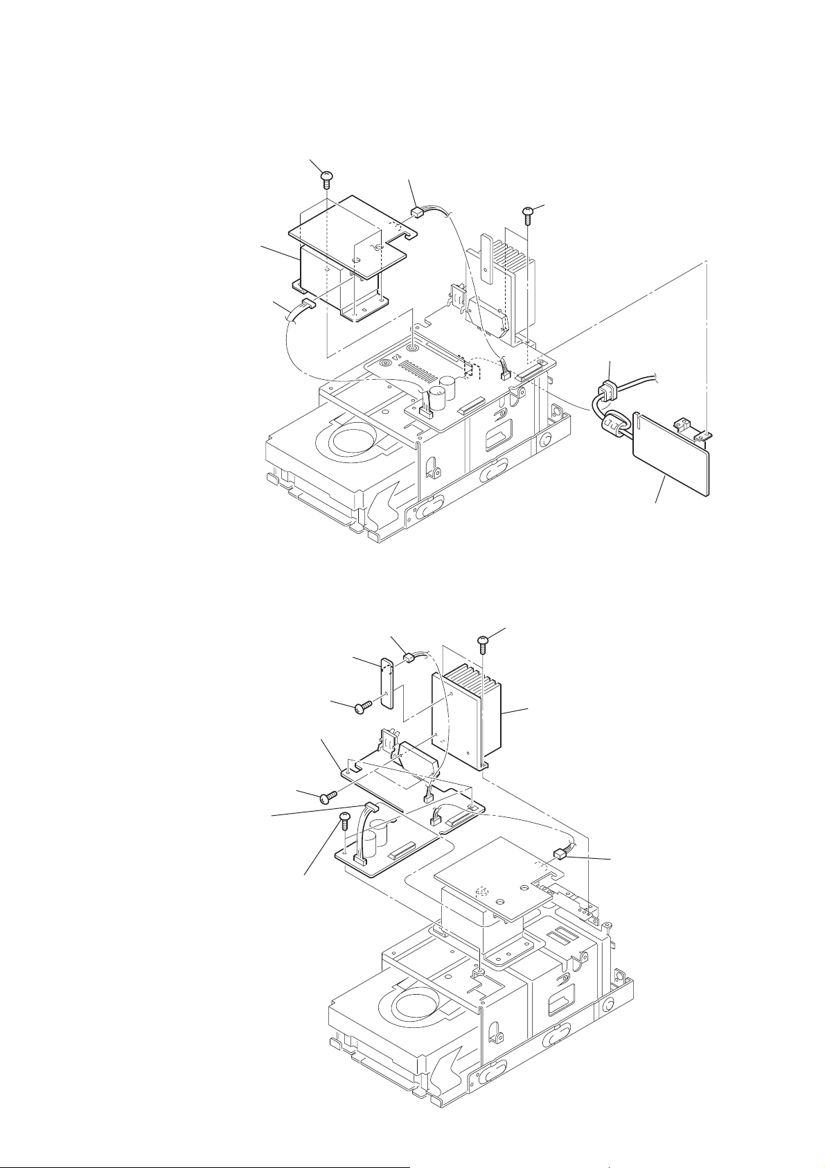
3-11. SUB POWER Board, Power Transformer (T901)
r
6
four screws
(
7
power transformer
(T901)
5
connector
(CN902)
+BVTT 4 × 8
)
4
connector
(CN903)
1
two screws
(
+BVTP 3 × 8
2
cord bushing
HCD-CV40
)
3-12. THERMAL Board, AMP Board
7
THERMAL board
6
screw
+BVTP 3 × 8
(
q;
AMP board
8
two screws
(
+BVTP 3 × 16
2
connector
(CN902)
3
(
)
three screws
+BVTP 3 × 8
5
)
)
connector
(CN803)
4
two screws
+BVTP 3 × 8
(
9
heat sink
3
SUB POWER board
)
1
connecto
(CN903)
13

HCD-CV40
3-13. CD Mechanism Deck (CDM63E)
6
CD mechanism deck
(CDM63E)
3
two screws
(
+BVTP 3 × 8)
4
chassis assy
1
flat type wire (28 core)
(CN101)
5
four screws
(
+BVTP 3 × 8
2
three screws
(
+BVTP 3 × 8
)
Note: When installing the CD mechanism, the four bosses
must be aligned with the specified positions.
)
14
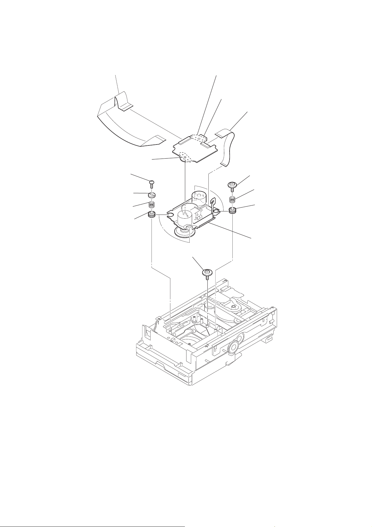
3-14. CD Base Unit (BU-30BD62)
)
1
flat type wire (28 core)
qs
Remove two solderings
2
two screws (+BVTP 2.6
3
two stoppers
4
two coil springs
(insulators)
5
two insulators
×
HCD-CV40
qa
Remove two solderings
qf
BD board
qd
flat type wire (16 core)
8)
6
two screws (+PTPWH M2.6
7
two coil springs
(insulators)
8
two insulators
9
screw (DIA. 12)
q;
BU-30BD62
15
HCD-CV40
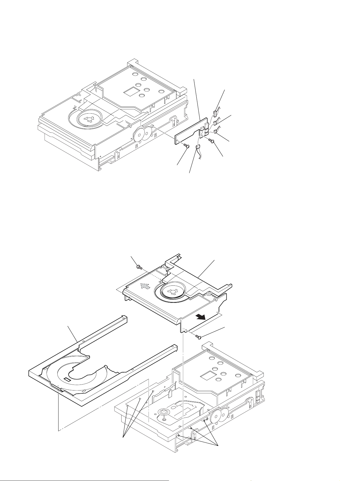
3-15. DRIVER Board
5
screw (BTTP M2.6)
7
DRIVER board
1
connector (CN705)
4
connector (CN703)
3
connector (CN704)
2
connector (CN702)
6
screw (BTTP M2.6)
3-16. Fitting Base (Stabilizer) Assy, Tray Assy
2
two screws (BTTP M2.6)
tray assy
8
4
7
fitting base (stabilizer) assy
3
1
two screws (+BTTP M2.6)
16
6
three bosses
5
three bosses

3-17. TRAY SENSOR Board
2
two screws (+BTTP M2.6)
4
two screws (+BTTP M2.6)
5
TRAY SENSOR board
1
Rotate the cam,
and lift up the stocker
at the full.
stocker
6
holder (sensor)
3
Cam
HCD-CV40
3-18. Slider (Loading), Gear (Slider)
3
two screws (+BTTP M2.6)
6
slider (loading)
4
bracket (retainer)
8
two gears (slider)
2
bracket (retainer)
1
two screws (+BTTP M2.6)
5
floating screw
7
two floating screws
17
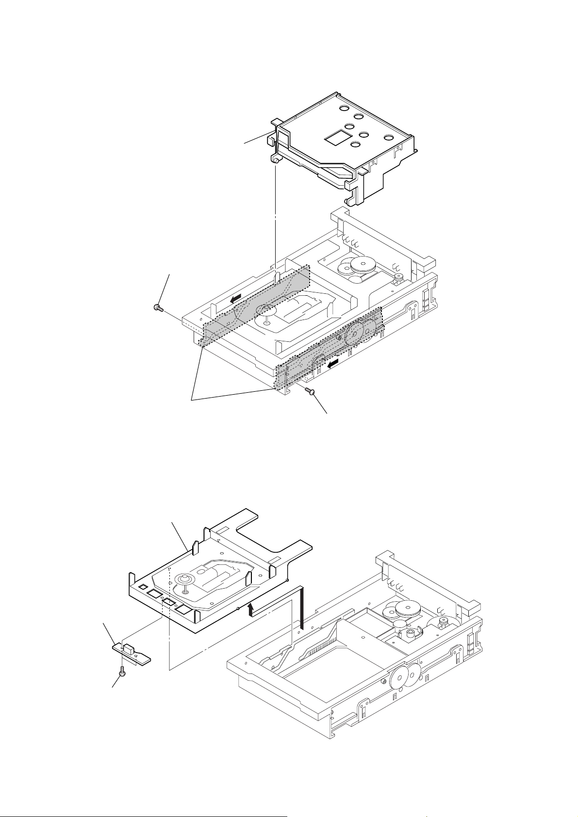
HCD-CV40
3-19. Stocker Assy
4
2
screw (+BTTP M2.6)
stocker assy
A
3
slide the slider (BU.L),
slider (BU.R) in the direction of
A
arrow
at the full.
3-20. DISC SENSOR Board
2
CD base unit assy
4
DISC SENSOR board
A
1
screw (+BTTP M2.6)
1
18
3
two screws (+BTTP M2.6)
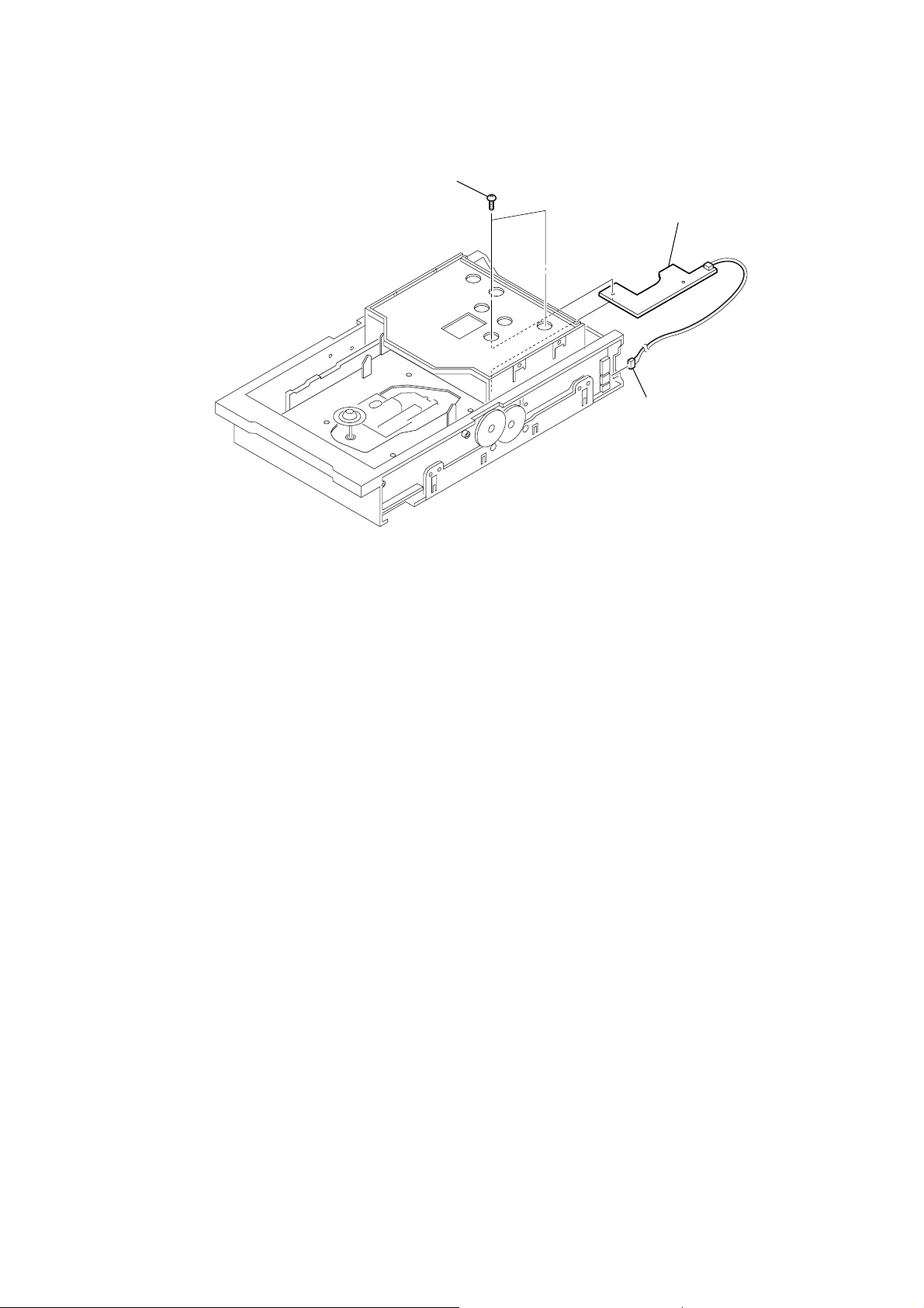
3-21. IN OUT SW Board
2
two screws (+BTTP M2.6)
3
IN OUT SW board
1
connector (CN704)
HCD-CV40
19

HCD-CV40
)
3-22. Motor Assy (M721), MOTOR Board
1
belt
2
connector (CN702
MOTOR board bottom view
3
Remove two solders.
6
4
two screws (+BTTP M2.6)
5
MOTOR board
7
motor assy (M721)
20

SECTION 4
TEST MODE
HCD-CV40
[Cold Reset]
• The cold reset clears all data including preset data stored in the
RAM to initial conditions. Execute this mode when returning
the set to the customer.
Procedure:
1. Press three buttons x , ENTER and ?/1 simultaneously.
2. The set is reset.
[CD Ship Mode]
•This mode moves the optical pick-up to the position durable to
vibration. Use this mode when returning the set to the customer
after repair.
Procedure:
1. Press the ?/1 button to turn the set on.
2. Select the function “CD”.
3. Press the DISC 1 button and the FUNCTION button simulta-
neously.
4. After the “STANDBY” display blinks six times, a message
“LOCK” is displayed on the liquid crystal display, and the CD
ship mode is set.
[GC Test Mode]
•This mode is used to check the software version, LCD, LED
and keyboard.
Procedure:
1. Press the ?/1 button to turn the set on.
2. Press three buttons x , ENTER and DISC 2 simultaneously.
3. LEDs and segments of liquid crystal display are all turned on.
4. When you want to enter the software version display mode,
press DISC 1 . The model number and destination are displayed.
5. Each time the DISC 1 button is pressed, the display changes
starting from MC version, GC version, CD version, CDD
version, CDMA version, CDMB version, BDA version, BDB
version, ST version, TA version, TM version, TC version and
MD version in this order. By pressing the DISC 3 the date of
the software version is displayed.
6. Press the DISC 2 button, and the key check mode is acti v ated.
7. In the key check mode, the liquid crystal display displays “K 0
J 0 V 0”. Each time a b utton is pressed, “K 0” v alue increases.
However, once a button is pressed, it is no longer taken into
account.
“V 0” value increases like 1, 2, 3 ... if rotating VOL knob in
“+” direction, or it decreases like 0, 9, 8 ... if rotating in
“–” direction.
8. To exit from this mode, press three b uttons in the same manner
as step 2, or disconnect the power cord.
[MC Test Mode]
•This mode is used to check operations of the respective sections
of Amplifier, Tuner, CD and Tape.
Procedure:
1. Press the ?/1 button to turn on the set.
2. Press the three buttons of x , ENTER and DISC 3 simulta-
neously.
3. “MD” is displayed and “ ( g) ” blinks.
4. Every pressing the EQ EDIT button changes the displays in
the order of
5. When the VOL control knob is turned to “+” direction even
slightly, the sound volume increases to its maximum and a
message “VOL MAX” appears for two seconds, then the display
returns to the original display.
6. When the VOL control knob is turned to “–” direction even
slightly, the sound volume decreases to its minimum and a
message “VOL MIN” appears for two seconds, then the display
returns to the original display.
7. Press the FUNCTION button to the TUNER.
“GEQ MIN” t“GEQ FLAT” t“GEQ MAX”
8. By pressing the PLA Y MODE/TUNING MODE button, select
the preset tuning.
9. The default-preset channel is selected. (It means that the
memory is cleared.)
10. When a tape is inserted in Deck and recording is started, the
input source function selects MD automatically.
11. During the recording by turning the m/M knob, the Tape
(Deck) is selected and tape is rewound. Tape stops at around
the record-starting position and playback of the recorded portion
of the tape is started.
12. Press the ?/1 button to turn the set off. The cold reset is en-
forced at the same time.
[CD Service Mode]
•This mode can run the CD sled motor freely. Use this mode, for
instance, when cleaning the optical pick-up.
Procedure:
1. Press the ?/1 button to turn the set on.
2. Select the function “CD”.
3. Press three buttons x , FUNCTION and DISC 2 simultaneously.
4. The CD service mode is selected.
5. With the CD in stop status, turn the m/M knob up to move
the optical pick-up to outside track, or turn the m/M knob
downword to move the optical pick-up to inside track.
6. To exit from this mode, perform as follows:
1) Move the optical pick-up to the most inside track.
2) Press ?/1 button to turn the set off.
Note: • Always move the optical pick-up to most inside track when exit-
ing from this mode. Otherwise, a disc will not be unloaded.
• Do not run the sled motor excessively, otherwise the gear can be
chipped.
[CD Ship (Memory Clear) Mode]
• Set the CD ship mode and set the default setup when shipped
from the factory at the next AC power on.
Procedure:
1. Press the ?/1 button to turn the set on.
2. Select the function “CD ”.
3. Press three buttons x , FUNCTION and DISC 1 simulta-
neously.
4. After the “STANDBY” display blinks six times, a message
“LOCK” is displayed on the liquid crystal display, and the CD
ship mode is set.
[CD Repeat 5 Times Limit Release Mode]
•5 times limit of repeating CD is released.
Procedure:
1. Press the ?/1 button to turn the set on.
2. Press three buttons x , FUNCTION and Z (DISC 1).
3. 5 times limit of repeating CD is released.
4. Cold reset is performed at power off.
[CD Lock Mode ]
•This mode locks the tray and a CD in the set even after poweroff.
Procedure:
1. Press the ?/1 button to turn the set on.
2. Set a CD in the set.
3. Press two buttons x and Z (DISC 1) simultaneously for five
seconds.
4. The message “LOCKED” is displayed and the tray is locked.
5. After the power-off, the tray is still locked.
6. To unlock the tray , press two buttons x and Z (DISC 1)
simultaneously for five seconds.
7. The message “UNLOCKED” is displayed and the tray is
unlocked.
21

HCD-CV40
[Color System Selection]
* Color system can be changed to PAL, NTSC or AUTO.
Procedure:
1. Turn the power off.
2. Press two buttons Z (DISC 1) and ?/1 at the same time.
“COLOR PAL” is displayed and the color system is changed
to PAL.
The set is powered on and the function is set to “CD”.
3. If the Z (DISC 2) and ?/1 buttons are pressed at the same
time in the step 2.
“COLOR AUTO” is displayed and the color system is set to
AUTO.
4. If the Z (DISC 3) and ?/1 buttons are pressed at the same
time in the step 2.
“COLOR NTSC” is displayed and the color system is set to
NTSC.
[Change-over of AM Tuner Step between 9 kHz and 10 kHz]
•A step of AM channels can be changed over betw een 9 kHz and
10 kHz.
Procedure:
1. Press the ?/1 button to turn the set on.
2. Select the function “TUNER”, and press the TUNER/BAND
button to select the band “AM”.
3. Press the ?/1 button to turn the set off.
4. Press two buttons REPEAT/FM MODE and ?/1 simulta-
neously, and the LCD changes to “AM 9 kHz STEP” or “AM
10 kHz STEP”, and thus the channel step is changed over.
22

SECTION 5
test tape
P-4-A100
(10kHz, –10dB)
MAIN board
CN322
Pin
5
or TP42 (L-CH)
Pin
9
or TP46 (R-CH)
level meter
set
+
–
MECHANICAL ADJUSTMENTS
HCD-CV40
SECTION 6
ELECTRICAL ADJUSTMENTS
Precaution
1. Clean the following parts with a denatured alcohol-moistened
swab:
record/playback heads pinch rollers
erase head rubber belts
capstan idlers
2. Demagnetize the record/playback head with a head demagnetizer.
3. Do not use a magnetized screwdriver for the adjustments.
4. After the adjustments, apply suitable locking compound to the
parts adjusted.
5. The adjustments should be performed with the rated power
supply voltage unless otherwise noted.
Torque Measurement
Mode
FWD
FWD
back tension
REV
REV
back tension
FF/REW
FWD tension
REV tension
Torque meter Meter reading
3.04 – 6.96 mN • m
CQ-102C
CQ-102C
CQ-102RC
CQ-102RC
CQ-201B
CQ-403A
CQ-403R
(31 to 71 g • cm)
(0.43 – 0.98 oz • inch)
0.20 – 0.58 mN • m
(2 to 6 g • cm)
(0.02 – 0.08 oz • inch)
3.04 – 6.96 mN • m
(31 to 71 g • cm)
(0.43 – 0.98 oz • inch)
0.20 – 0.58 mN • m
(2 to 6 g • cm)
(0.02 – 0.08 oz • inch)
6.97 – 14.02 mN • m
(71 to 143 g • cm)
(0.98 – 1.99 oz • inch)
9.8 mN • m or more
(100 g • cm or more)
(1.4 oz • inch or more)
9.8 mN • m or more
(100 g • cm or more)
(1.4 oz • inch or more)
DECK SECTION 0 dB=0.775V
1. Demagnetize the record/playback head with a head demagnetizer.
2. Do not use a magnetized screwdriver for the adjustments.
3. After the adjustments, apply suitable locking compound to the
parts adjusted.
4. The adjustments should be performed with the rated power
supply voltage unless otherwise noted.
5. The adjustments should be performed in the order given in this
service manual. (As a general rule, playback circuit adjustment
should be completed before performing recording circuit
adjustment.)
6. The adjustments should be performed for both L-CH and RCH.
7. Switches and controls should be set as follows unless otherwise
specified.
Signal Used forTape
P-4-A100
WS-48B
[Record/Playback Head Azimuth Adjustment]
Procedure:
1. Mode : Playback
2. Turn the adjustment screw and c heck output peaks. If the peaks
do not match for L-CH and R-CH, turn the adjustment screw
so that outputs match within 1 dB of peak.
10 kHz, –10 dB
3 kHz, 0 dB
Azimuth Adjustment
Tape Speed Adjustment
L-CH
peak
screw
position
R-CH
peak
output
level
within
1 dB
L-CH
peak
R-CH
peak
within 1dB
screw
position
23
 Loading...