

Page 1

Trinitron" Coior
Graphic Dispiay
3-864-156-21 (1)
Operating Instructions
Mode d’emploi
Manual de instrucciones
_______
GDM-F500
> 1998 by Sony Corporation
Page 2

Owner’s Record
The model and serial numbers are located at the rear of the unit.
Record these numbers In the spaces provided below. Refer to them
whenever you call upon your dealer regarding this product.
Model No.
______________
Serial No.
____________________
WARNING
To prevent fire or shock hazard, do not expose the
unit to rain or moisture.
Dangerously high voltages are present inside the
unit. Do not open the cabinet. Refer servicing to
qualified personnel only.
FCC Notice
This equipment has been tested and found to comply with the limits
for a Class B digital device, pursuant to Part 15 of the FCC Rules.
These limits are designed to provide reasonable protection against
harmful interference in a residential installation. This equipment
generates, uses, and can radiate radio frequency energy and, if not
installed and used in accordance with the instructions, may cause
harmful interference to radio communications. However, there is no
guarantee that interference will not occur in a particular installation.
If this equipment does cause harmful interference to radio or
television reception, which can be detemiined by turning the
equipment off and on, the user is encouraged to try to correct the
interference by one or more of the following measures:
- Reorient or relocate the receiving antenna.
- Increase the separation between the equipment and receiver.
- Connect the equipment into an outlet on a circuit different from
that to which the receiver is connected.
- Consult the dealer or an experienced radio/TV technician for help.
You are cautioned that any changes pr modifications not expressly
approved in this manual could void your authority to operate this
equipment.
IMPORTADOR (Para Mexico unicamente/For Mexico only)
Sony Electrónicos de Mexico, S.A. de C.V.
Henry Ford No.29
Fraccionamiento San Nicolas, Tlalnepantla
Estado de Mexico, CP54030
Tel.: 321-1000
R.F.C. SEM-941001-BJA
Hinweise
• Aus ergonomiscnen Gründen wird empfohlen, die
Grundfarbe Blau nicht aut dunklem Untergrund zu verwenden
(schlechte Erkennbarkeit, Augenbelastung bei zu geringem
Zeichenkontrast).
• Aus ergonomischen Gründen (flimmern) sollten nur
Darstellungen bei Vertikalfrequenzen ab 70 Hz (ohne
Zeilensprung) verwendet werden.
• Die Konvergenz des Bildes kann sich auf Grund des
Magnetfeldes am Ort der Aufstellung aus der korrekten
Grundelnstellung verändern. Zur Korrektur empfiehlt es sich
deshalb, die Regler an der Frontseite für Konvergenz so
einzustellen, daß die getrennt sichtbaren Farblinien für Rot.
Grün und Blau bei z.B. der Darstellung eines Buchstabens
zur Deckung (Konvergenz) gelangen.
Siehe hierzu auch die Erklärungen zu Konvergenz.
NOTICE
This notice is applicable for USA/Canada only.
If shipped to USA/Canada, install only a UL LISTED/CSA
LABELLED power supply cord meeting the following
specifications:
SPECIFICATIONS
Plug Type Nema-Plug 5-15p
Cord Type SVT or SJT, minimum 3x18 AWG
Length Maximum 15 feet
Rating Minimum 7 A, 125 V
NOTICE
Cette notice s'applique aux Etats-Unis et au Canada
uniquement.
Si cet appareil est export* aux Etats-Unis ou au Canada,
utiliser le cordon d’alimentation portant la mention UL LISTED/
CSA LABELLED et remplissant les conditions suivantes:
SPECIFICATIONS
Type de fiche Fiche Nema 5-15 broches
Cordon Type SVT ou SJT, minimum 3x18 AWG
Longueur Maximum 15 pieds
Tension Minimum 7 A, 125 V
IMPORTANTE
Para prevenir cualquier mal funcionamiento у evitar daños, рог
favor, lea detalladamente este manual de instrucciones antes
de conectar y operar este equipo.
INFORMATION
This product complies with Swedish National Council for Metrology
(MPR) standards issued in December 1990 (MPR II) for very low
frequency (VLF) and extremely low frequency (ELF).
INFORMATION
Ce produit est conforme aux normes du Swedish National Council
for Metrology de décembre 1990 (MPR II) en ce qui concerne les
fréquences très basses (VLF) et extrêmement basses (ELF).
Hinweis
Dieses Gerät erfüllt bezüglich tieffrequenter (very low frequency)
und tiefstfrequenter (extremely low frequency) Strahlung die
Vorschriften des .Swedish National Council for Metrology (MPR)"
vom Dezember 1990 (MPR II).
INFORMACIÓN
Este producto cumple las normas del Conseio Nacional Sueco
para Metrología (MPR) emitidas en diciembre de 1990 (MPR II)
para frecuencias muy bajas (VLF) y frecuencias extremadamente
bajas (ELF).
Dieses Garát entspricht den folgenden europäischen EMVVorschriften für Betrieb in Wohngebieten, gewerblicher Gebieten
und Leichtindustriegebieten.
EN55022/1994 Klasse B
EN50082-1/1992
EN61000-3-2/1995
As an ENERGY STAR Partner, Sony
Corporation has determined that this
product meets the ENERGY STAR
guidelines for energy efficiency.
This monitor complies with the
TCO’95 guidelines.
Declaration of Conformity
Trade Name: Sony
Model No.: GDM-F500
Responsible Party: Sony Electronics Inc.
Address: 1 Sony Drive. Park Ridge, NJ. 07656 USA
Telephone No.: 201-930-6970
This device complies with Part 15 of the FCC Rules. Operation
is subject to the following two conditions: (1) This device may
not cause harmful interference, and (2) this device must accept
any interference received, including interference that may
cause undesired operation.
Page 3

Table of Contents
y*- -
Precautions...............................................................................................4
identifying parts and controls.................................................................5
Setup
.............................................................................................
step 1 : Connect your monitor to your computer...................................6
Step 2: Connect the power cord..............................................................7
Step 3: Turn on the monitor and computer
............................................
Connecting Universal Serial Bus (USB) compliant peripherals .... 8
Selecting the on-screen menu language (LANG)
..................................
Selecting the input signal........................................................................9
Automatically sizing and centering the picture
Customizing Your Monitor
........................................................
.....................................
Navigating the menu..............................................................................10
Adjusting the brightness and contrast
Adjusting the centering of the picture (CENTER)
Adjusting the size of the picture (SIZE)
Adjusting the shape of the picture (GEOM)
................................................
...............................
...............................................
.........................................
Enlarging or reducing the picture (ZOOM)...........................................12
Adjusting the color of the picture (COLOR)
Adjusting the quality of the picture (SCREEN)
Additional settings (OPTION)
................................................................
.........................................
....................................
Resetting the adjustments.....................................................................14
6
7
8
9
10
11
11
11
12
12
13
14
Trinitron® is a registered trademark or
Sony Corporauon.
Macintosh is a trademark licensed to
Apple Computer, Inc., registered in the
U S.A. and other countries.
Windows® and MS-DOS are registered
trademarks of Microsoft Corporation in
the United States and other countnes.
IBM PC/AT and VGA are registered
trademarks of IBM Corporauon of the
U.S.A.
VESA and DDC ” are uademarks ot the
Video Electronics Standard
■Association.
ENERGY Star is a U.S. regisiered
mark.
All other product names mentioned
herein may be the trademarks or
registered trademarks of their respecuve
companies.
Furthermore. and "®" are not
menuoned in each case m this manual.
Technical Features.....................................................................15
Preset and user modes..........................................................................15
Power saving function...........................................................................15
T roubieshooting....................................................................... 15
If thin lines appear on your screen (damper wires)
On-screen messages
Trouble symptoms and remedies
............................................................................
.........................................................
Self-diagnosis function..........................................................................18
............................
15
Specifications.............................................................................18
Appendix........................................................................................i
Preset mode timing table...........................................................................>
TCO’95 Eco-document
...............................................................................
15
16
'
Page 4
Precautions
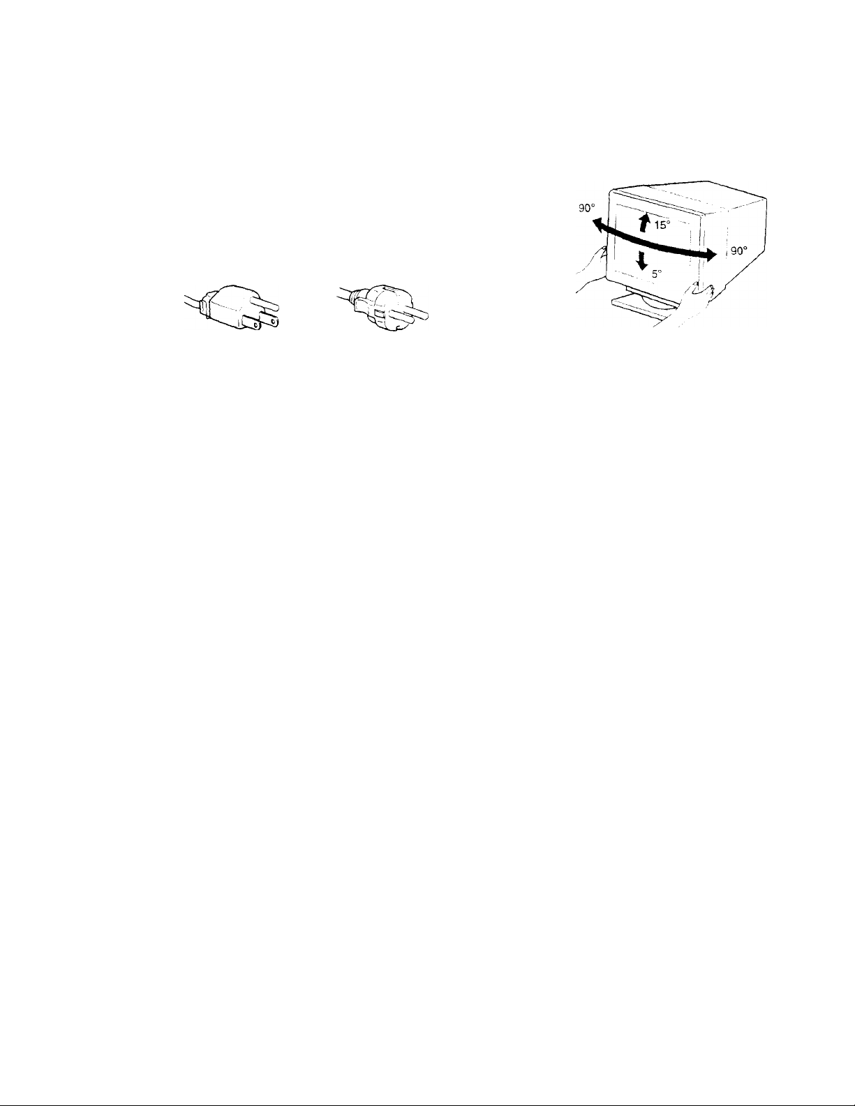
Warning on power connections
• Use the supplied power cord. If you use a different power cord,
be sure that it is compatible with your iocai power supply.
For the customers in the U.S.A. ».
if you do not use the appropnate cord, this moniior will not
conform to mandatory FCC standards.
Example of plug types
for 100 to 120 VAC for 200 to 240 V AC
Before disconnecung the power cord, wait at least 30 seconds
after turning off the power to allow the static electricity on the
screen’s surface to discharge.
After the power is turned on, the screen is demagnetized
(degaussed) for about 3 seconds. This generates a strong
magnetic field around the screen which may affect data stored
on magnetic tapes and disks placed near the momtor. Be sure to
keep magnetic recording equipment, tapes, and disks away
from the monitor.
Use of the tiit-swivel
This monitor can be adjusted within the angles shown below. To
turn the monitor vertically or honzomally. hold it at the bottom
with both hands.
The equipment should be installed near an easuy accessible
outlet
Installation
Do not install the monitor in the following places:
• on surfaces (rugs', blankets, etc.) or near matenais (curtams,
draperies, etc,) that may block the ventilation holes
• near heat sources such as radiators or air ducts, or in a place
subject to direct sunlight
• in a place subject to severe temperature changes
• tn a place subject to mechanical vibration or snock
• on an unstable surface
• near cqmpment which generates magnetism, suen as a
transformer or high voltage power lines
• near or on an electrically charged metai surface
Maintenance
• Clean the screen with a soft cloth. If you use a glass cleaning
liquid, do not use any type of cleaner containing an anti-static
solution or similar additive as this may scratch the screen’s
coating.
• Do not rub. touch, or tap the surface of the screen with sharp or
abrasive items such as a ballpoint pen or screwdriver. This type
of contact may result in a scratched picture tube.
• Clean the cabinet, panel and controls with a soft cloth lightly
moistened with a mild detergent solution. Do not use any type
of abrasive pad, scounng powder or solvent, such as alcohol or
benzene.
Transportation
When you transport this monitor for repair or shipment, use the
original carton and packing matenais.
Page 5
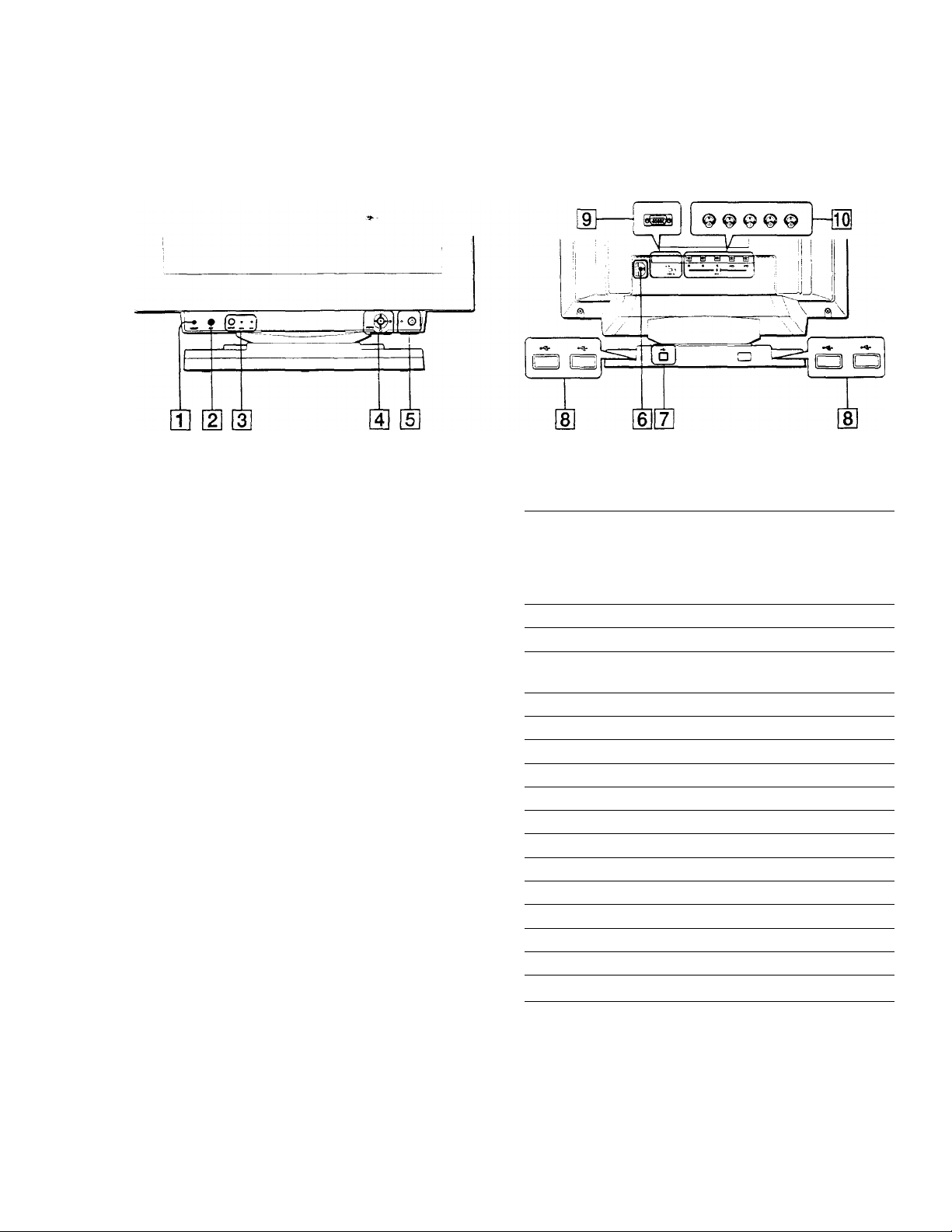
Identifying parts and controls
See the pages m parentheses for further details.
Front
Q] RESET button (page 14)
This button resets the adjustments to the factory settmgs.
[2] ASC (auto sizing and centering) button (page 9)
This button automatically adjusts the size and centenng of the
picture.
[3] INPUT button and HD 15/BNC indicators (page 9)
This button selects the HD15 or BNC video input signal. The
input signal and corresponding input indicator change each
time you press this button.
[4] Joystick (page 11).
The joystick is used to display the menu and make
adjustments to the monitor, including brighmess and contrast
adjustments.
[H (!) (power) switch and indicator (pages 7,15,18)
This button turns the momtor on and off. The power indicator
lights up in green when the momtor is turned on, and either
flashes in green and orange, or hghts up m orange when the
monitor is in power saving mode.
[U AC IN connector (page 7)
This connector provides AC power to the monitor.
\j] USB (universal serial bus) upstream connector
(page 8)
Use this connector to link the momtor to a USB compliant
computer.
[8] USB (universal serial bus) downstream connectors
(page 8)
Use these connectors to link USB penpheral devices to the
monitor.
Rear
[|] Video input 1 connector (HD15) (page 6)
This connector inputs RGB video signals (0.700 Vp-p,
positive I and sync signals.
\ ®(9)®@(6) /
y
Pin No. Signal
1
2
3 Blue
4 ID (Ground)
5 DDC Ground*
6 Red Ground
7
8
9 DDC + 5V*
10 Ground
11
12
13 H. Sync
14 V. Sync
15
♦ DDC (Display Data Channel) is a standard of VESA.
!lOi Video input 2 connector (BNC) (page 6)
This connector inputs RGB video signals (0.700 Vp-p,
positive) and sync signals.
Red
Green
(Composite Sync on Green)
Green Ground
Blue Ground
ID (Ground)
Bi-Directional Data (SDA)*
Data Clock (SCD*
Page 6
Setup
Before using your monitor, check that the following accessones
are included in your canon:
• Power cord (1)
• HD15 video signal cable (1)
• USB cable (1)
• Macintosh adapter 11)
• Windows Monitor Informauon Disk (1)
• Warranty card (1)
• Notes on cleaning the screen's surface (1)
• This instruction manual (1)
Step 1: Connect your monitor to
your computer
Turn off the monitor and computer before connecting.
■ Connecting to an IBM PC/AT or compatible
computer
■ Connecting to a Macintosh or compatible
computer
Use the supplied Macintosh adapter.
Connect the supplied Macintosh adapter to the computer before
cotmecimg the cable. This adapter is compatible with Macintosh LC,
Performa, Quadra, Power Macintosh and Power Macintosh G3 series
computers. Macintosh H series and some older versions of PowerBook
models may need an adapter with micro switches (not supplied).
If your PC system is not compatible with Plug & Play (DDC2AB
or DDC2B+)
This monitor uses the No.9 pin m the video signal connector for Plug &
Play (DDC2AB or DDC2B+)compatibility. Seepage 5 for thelocauonof
the No.9 pin,
• If your computer accepts the No.9 pin, use the supplied HD15 video
signal cable.
• If your computer does not accept the No.9 pin, please consult your
dealer for advice on obtairung an HD 15 adapter.
I Connecting to the five BNC connectors
to SYNC IN
Refer to the preceding
examples to connect to your
computer.
Connect the cables from left to right in the following order Red-GreenBlue-HD-VD.
Notes
• Do not touch the pins of the video cable connector as this might bend
the pins.
• Plug & Play (DDC) does not apply to the five BNC connectors. If you
want to use Plug & Play, connect your computer to the HDl 5 connector
using the supplied video signal cable.
video signal cable
(SMF-400, not supplied)*
HD/VD
Page 7

step 2: Connect the power cord
Step 3;Turn on the monitor and
With the monitor and computer switched off. first connect the
power cord to the monitor, then connect it to a power outlet.
computer
First turn on the monitor, then turn on the computer.
O
The installation of your momtor is complete.
If necessary, use the monitor's controls to adjust the picture.
If no picture appears on your screen
• Check that the momtor is correctly connected to the computer.
• If NO INPUT SIGN AL appears on the screen, try changing the
tnput signal (page 9), and confirm that your computer's graphic
board is completely seated in the correct bus slot.
• If you are replacing an old momtor with this model and OUT
OF SCAN RANGE appears on the screen, reconnect the old
monitor. Then adjust the computer’s graphic board so that the
horizontal frequency is between 30 - 121 kHz, and the vertical
frequency is between 48- 160 Hz,
For more information about the on-screen messages, see "Trouble
symptoms and remedies" on page 16.
For customers using Windows 95/98
To maximize the potential of your monitor, install the new model
information file from the supplied Windows Momtor Infonnation Disk
onto your PC.
This monitor complies with the “VESA DDC’ Plug & Play standard. If
your PC/graphics board complies with DDC, select “Plug & Play Monitor
(VESA DDC)” or this monitor’s model name as the monitor type in the
“Control Panel” of Windows 95/98. If your PC/graphics board has
difficulty communicating with this monitor, load the Windows Monitor
Information Disk and select this monitor’s model name as the monitor
type.
For customers using Windows NT4.0
Monitor semp in Windows NT4.0 is different from Windows 95/98 and
does not involve the selection of monitor type. Refer to the Windows
NT4.0 instruction manual for further details on adjusting the resolution,
refresh rate, and number of colors.
Adjusting the monitor's resolution and color number
Adjust the monitor’s resolution and color number by referring to your
computer's instruction manual. The color number may vary according to
your computer or video board. The color palette setting and the actual
number of colors are as follows:
’ High Color (16 bit) —► 65.536 colors
• True Color (24 bit) —► about 16.77 million colors
In true color mode (24 bit), speed may be slower.
Page 8

Connecting Universal Serial Bus
(USB) compliant peripherals
Selecting the on-screen menu
language (LANG)
Your monitor has one upstream and four downstream USB
connectors. They provide a fast and easy way to connect USB
compliant penpheral devices (such as keyboards, mice, pnnters
and scanners) to your computer using a standardized USB cable.
To use your monitor as a hub for your peripheral devices, connect
the USBs as illustrated below.
peripheral devices
penpheral devices
1 Turn on the monitor and computer.
2 Connect your computer to the square upstream
connector using the. supplied USB cable.
English, French, German. Spamsh. Italian, and Japanese versions
of the on-screen menus are available. The default setting is
English.
1 Press the joystick
See page 11 for more information on using the joystick.
2 Move the joystick to highlight Q LANG and press
the joystick again.
FRANÇAIS
DEUTSCH
ESPAÑOL
ITALIANO
For customers using Windows
If a message appears onyour screen, follow tfie on-screen instnicuons
and select Generic USB Hub as the default settmg.
3 Connect your USB compliant peripheral devices to
the rectangular downstream USB connectors.
Notes
• Not all computers and /or operaune systems suppon USB
configurations. Check your computer ' s instrucuon manual to see u you
can connect USB devices.
• In most cases, USB driver software needs to be installed on the host
computer. Refer to the penpheral device’s instrucuon manual for
further details.
• The monitor functions as a USB hub as long as the momtor ts either
“on” or in power saving mode.
• If you connect a keyboard or mouse to the USB connectors and then
boot your computer for the first time, the peripheral devices mav not
function. First connect the keyboard and mouse directly to the
computer and set up the USB compliant devices. Then connect them to
this momtor.
• Do not lean on the momtor when pluggmg in the USB cables. The
momtor may suddenly shift and cause mjury.
3 Move the joystick up or down to select a language
and press the joystick again.
• ENGUSH
• FRANÇAIS; French
• DEUTSCH: German
• ESPAÑOL: Spamsh
• ITALIANO: Italian
• S:$:g: Japanese
To close the menu
Press the joystick once to remm to the mam menu, and twice to return to
normal viewing. If no buttons are pressed, the menu closes automatically
after about 30 seconds.
To reset to English
Press-the RESET button while the LANGUAGE menu is displayed on the
Page 9

Selecting the input signal
You can connect two computers to this monitor using the HD 15
and BNC connectors. To switch between the two computers, use
the INPUT button.
Automatically sizing and centering
the picture
You can easily adjust the picture to fill the screen by pressing the
\SC (auto sizing and centenng) button.
Press the INPUT button. ^
The input signal and corresponding input indicator change each
time you press this button.
O O
INPUT'hDIS BNC
Notes
• If no signal is input to the selected connector, the monitor automatically
switches to the other connector.
• If you restart the computer you want to view, or that computer is in
power saving mode, the monitor may automatically switch to the other
connector's signal. If this happens, manually select the desired signal
usmg the INPUT button.
Press the ASC button.
The picture automatically fills the screen.
Notes
• This funcuon is uitended for use with a computer mnning Windows or
similar graphic user interface software that provides a full-screen
picture. It may not work properly if the background color is dark or if
the input picture does not fill the screen to the edges (such as an MSDOS prompt).
• Pictures with an aspect ratio of 5:4 (resolution: 1280 x 1024. 1800 x
1440) are displayed at their actual resolution and do not fill the screen
to the edges.
• The screen may go blank for a few seconds when the ASC button is
pressed. This is not a malfunction.
y
Page 10

Customizing Your Monitor
You can make numerous adjustments to your monitor using the
on-screen menu.
Navigating the menu
Press the joystick to display the main MENU on your screen. See
page 11 for more information on using the joystick.
lS
"TQ Pi C3^ ¡1*1!
COLORÍ CENTEB ËOEEEN
-•n
GEOM
! G !, I« < tel
UNG I I SIZE
T(03
ss
ZOOM
e
IQPTIONI
i6J SCREEN (page 13)
Select the SCREEN menu to adjust
the picture’s quality. You can adjust
the vertical and horizontal
convergence, landing, and moire
cancellation effect.
[7] LANG (page 8)
Select LANG to choose the on
screen menu's lanauage.
il] OPTION (page 14)
Select OPTION to ad just the
momtor’s options. The options
include:
• degaussing the screen
• changmg the on-screen menu
position
• changing the power savina delay
time
• locking the controls
FRANÇAISFRANÇAIS
DEUTSCH
ESPAÑOL
ITALIANO
ON 0
o
0: 5 SEC
O^: UNLOCK
MANUAL DEGAUSS
Use the joystick to select one of the following menus.
[T] CENTER (page 11)
Select the CENTER menu to adjust
the picture's centenng.
SIZE (page 11)
Select the SIZE menu to adjust the
picture’s honzontal and vertical
size.
GEOM (page 12)
Select the GEOM menu to adjust the
picture’s rotation and shape.
¡4] ZOOM (page 12)
Select the ZOOM menu to enlarge
or reduce the picture.
[g EXIT
Select EXIT to dose the menu.
COLOR (page 12)
Select the COLOR menu to adjust
the picture’s color temperature. You
can use this to match the momtor’s
colors to a pnnted Dicture's colors.
5000K i 6500K ^
■rn
R BIAS
a
BIAS
wmfz 0
G
a
B BIAS
a■CD
R GAIN
aKZ
—
GAIN
G
Q
GAIN
B
a
am
□ 50 1
50 i
50 1
□
50 I
a
50 1
a
c
50 (
Page 11

■ Using the joystick
1 Select the menu you want to adjust.
Move the joystick up, down, left, or nght to highlight the
desired menu. Press the joystick to select the menu item.
2 Adjust the menu.
Move the joystick up, down, left, or nght to make the
adjustment.
3 Close the menu.
Press the joystick once to return to the mam menu, and twice
to return to normal viewing. If no buttons are pressed, the
menu closes automatically after about 30 seconds.
Adjusting the brightness and
contrast
Brightness and contrast adjustments are made using a separate
BRIGHTNESS/CONTRAST menu.
These settings are stored in memory for all input signals.
1 Move the joystick in any direction.
The BRIGHTNESS/CONTRAST menu appears on the
screen.
BRIGHTNESSCONTR AST
-a
□ 26 D a 26 Q
OkHz/ 75Hz
the honzontal and vertical frequencies of the
cunent input signal
2 Move the joystick up or down to adjust the
brightness (G ), and left or right to adjust the
contrast (3).
The menu automatically disappears after about 3 seconds.
Adjusting the centering of the
picture (CENTER)
■ Resetting the adjustments
Press the RESET button. See page 14 for more information on
resetting the adjustments.
RESET
This setting is stored in memory for the current input signal.
1 Press the joystick.
The main MENU appears on the screen.
2 Move the joystick to highlight CENTER and
press the joystick again.
The CENTER menu appears on the screen.
3 Move the joystick up or down to adjust the vertical
centering, and left or right to adjust the horizontal
centering.
Adjusting the size of the picture
(SIZE)
This setting IS stored m memory for the current input signal.
1 Press the joystick.
The mam MENU appears on the screen.
2 Move the joystick to highlight @ SIZE and press the
joystick again.
The SIZE menu appears on the screen.
3 Move the joystick up or down to adjust the vertical
size, and left or right to adjust the horizontal size.
11
Page 12

Adjusting the shape of the picture
(GEOM)
Adjusting the color of the picture
(COLOR)
The GEOM settings allow you to adjust the rotation and shape of
the picture. ^
The rotation setting is stored m memory for all input signals. ,\11
other settings are stored in memory for the current input signal.
1 Press the joystick.
The main MENU appears on the screen.
2 Move the joystick to highlight O GEOM and press
the joystick again.
The GEOMETRY menu appears on the screen.
3 First move the joystick up or down to select the
desired adjustment item. Then move the joystick left
or right to make the adjustment.
Select
O ROTATION
O PINCUSHION
D PIN BALfliNCE
O KEYSTONE
Q KEY BALANCE
-
To
rotate the picture
expand or contract the picture sides
shift the picture sides to the left or nght
adjust the picture width at the top of
the screen
shift the picture to the left or right at
the top of the screen
The COLOR settings allow you to adjust the picture’s color
temperature by changing the color level of the white color field.
Colors appear reddish if the temperature is low, and bluish if the
temperature is high. This adjustment is useful for matching the
monitor’s colors to a pnmed picture's colors.
This setting IS stored in memory for all input signals.
1 Press the joystick.
The mam MENU appears on the screen.
Move the joystick to highlight 0 COLOR and press
the joystick again.
The COLOR menu appears on the screen.
Move the joystick left or right to select a color
temperature.
The preset color temperatures are 5000K, 6500K. and 9300K
Since the default settmg is 9300K. the whites will change
from a bluish hue to a reddish hue as the temperature is
lowered to 6500K and 5000K.
If necessary, fine tune the color temperature.
First move the joystick up or down to select the desired
adjustment item. Then move the joystick left or right to mak
the adjustment.
Enlarging or reducing the picture
(ZOOM)
This setting IS stored in memory for the current mout sinnal.
1 Press the joystick.
The mam MENU appears on the screen.
2 Move the joystick to highlight iS ZOOM and press
the joystick again.
The ZOOM menu appears on the screen.
3 Move the joystick left or right to enlarge or reduce
the picture.
Note
.Adjustment stops when either the honzomai or venical size reaches ns
maximum or minimum value.
[T] Adjusting the BIAS (black level)
This changes the bnghtness of both the dark and light
areas of an image.
[2] Adjusting the GAIN (white level)
This changes the contrast of just the light areas ol an
image.
You can adjust the R(Red), G(Green), and B(BIue)
component of the input signal when making changes to ite
[T] and i'^.
If you fine tune the color temperature, the new color seta
are stored in memory for each of the three color temperati
and item |3] of the on-screen menu changes as follows:
• [5000K] —'ll
• [6500K1 i 2l
• (9300K] —:3|
Page 13

Adjusting the quality of the picture
(SCREEN)
The SCREEN settings allow you to adjust the quality of the
picture by controlling the convergence, moire, and landing.
• [f you see red or blue shadows around letters or lines, adjust the
convergence. »
• If elliptical or wavy patterns appear on the screen, cancel the
moire.
• If the color is irregular at the comers of the screen, adjust the
landing.
The CANCEL MOIRE and MOIRE ADJUST settings are stored
in memory for the current input signal. All other settings are
stored in memory for all input signals.
1 Press the joystick.
The main MENU appears on the screen.
2 Move the joystick to highlight [m] SCREEN and
press the joystick again.
The SCREEN menu appears on the screen.
Select To
□I
CANCEL MOIRE*
ШЗ ADJ
MOIRE ADJUST
• Moire is a type of natural interference which produces soft, wavy lines
on your screen. It may appear due to interference between the pattern
of the picture on the screen and the phosphor pitch pattern of the
monitor.
Example of moire
turn the moire cancellation function
ON or OFF
(H ADJ (MOIRE ADJUST) appears
in the menu when you select ON
adjust the degree of moire
cancellation until the moire is at a
minimum
3 First move the joystick up or down to select the
desired adjustment item. Then move the joystick left
or right to make the adjustment.
Select
QD
To
horizontally shift red or blue shadows
H CONVERGENCE
ca
vertically shift red or blue shadows
V CONVERGENCE
[S TOP
V CONVER TOP
(a вот
V CONVER ВОТ
□
LANDING
□ ADJ
LANDING ADJUST
vertically shift red or blue shadows at
the top of the screen
vertically shift red or blue shadows at
the bottom of the screen
select one of the four comers of the
screen
□ :top left □ ;top nght
□ ibottom left □ tbottom nght
reduce any irregularities in the color
of the comer selected in LANDING
to a minimum
Note
The picture may become fuzzy when CANCEL MOIRE is set to ON.
13
Page 14

Additional settings (OPTION)
Resetting the adjustments
You can manually degauss (demagneuzel the monitor, change the
menu position, set the power saving delay time, and lock the
controls.
1 Press the joystick.
The mam MENU appears on the screen.
2 Move the joystick to highlight g OPTION and press
the joystick again.
The OPTION menu appears on the screen.
3 Move the joystick to highlight the desired
adjustment item.
Adjust the selected item according to the following
Instructions.
Degaussing the screen
The monitor is automatically demagnetized when the power is
turned on.
To manually degauss the monitor, first move the
joystick up or down to select (MANUAL DEGAUSS).
Then move the joystick to the right.
The screen is degaussed for about 3 seconds. If a second degauss
cycle is needed, allow a minimum interval of 20 minutes for the
best result.
This monitor has the following three reset methods. Use the
RESET button to reset the adjustments.
RESET
Resetting a single adjustment item
Use the joystick to select the adjustment item you want to re
and press the RESET button.
Resetting all of the adjustment data for the current input signal
Press the RESET button when no menu is displayed on the sci
Note that the following items are not reset by this method;
• on-screen menu language (page 8)
• on-screen menu position (page 14)
• power saving delay time (page 14)
• control lock (page 14)
Resetting ail of the adjustment data for all inp signals
Press and hold the reset button for more than two seconds.
Changing the menu's position.
Change the menu’s position if it is blocking an image on the
screen.
To change the menu’s on-screen position, first move
the joystick up or down to select S (OSD H POSITION)
for horizontal adjustment, or (E3 (OSD V POSITION) for
vertical adjustment. Then move the joystick to the left
or right to shift the on-screen menu.
Changing the power saving delay time.
To adjust the time it takes to enter the power saving
mode, first move the joystick up or down to select ^
(PWR SAVE DELAY). Then move the joystick to the left
or right to select the desired time.
If you select OFF, the monitor does not enter power saving mode.
Sec page 15 for more information about the momtor’s power
saving capabilities.
Locking the controls.
To protect adjustment data by locking the controls, first
move the joystick up or down to select O-n (CONTROL
LOCK). Then move the joystick to the right to select
LOCK.
Only the (!) (power) switch, EXIT, and O-n (CONTROL LOCK)
of the S OPTION menu will operate. If any other items are
selected, the O-n mark appears on the screen.
Note
The RESET button does not function when 0*n (CONTROL LC
is set to LOCK.
To cancel the control lock
Repeat the procedure above and set o-n (CONTROL LOCK) to
UNLOCK,
14
Page 15

Technical Features
Preset and user modes
Troubleshooting
Before contacting technical support, refer to this section.
When the monitor receives an input signal^it automatically
matches the signal to one of the factory preset modes stored in the
monitor’s memory to provide a high quality picture at the center
of the screen. (See page i for a list of the factory preset modes.)
For input signals that do not match one of the factory preset
modes, the digital Multiscan technology of this momtor ensures
that a clear picture appears on the screen for any timing in the
monitor’s frequency range (horizontal: 30-121 kHz. vertical: 48
- 160 Hz). If the picture is adjusted, the adjustment data is stored
as a user mode and automatically recalled whenever the same
input signal is received.
Note tor Windows users
For Windows users, check your video board manual or the utihty
program which comes with your graphic board and select the
highest available refresh rate to maximize momtor penormance.
Power saving function
This monitor meets the power-saving guidelines set by VESA,
ENERGY STAR, and NUTEK. If the monitor is coimected to a
computer or video graphics board that is DPMS (Display Power
Management Signaling) comphant, the monitor will
automatically reduce power consumption in three stages as shown
below.
If thin lines appear on your screen
(damper wires)
The lines you are expenencmg on your screen are normal for the
Trinitron monitor and are not a malfunction. These are shadows
from the damper wires used to stabilize the apeiture grille and are
most noticeable when the screen’s background is light (usually
white). The aperture grille is the essential element that makes a
Trinitron picture tube unique by allowing more light to reach the
screen, resulting in a bnghter. more detailed picture.
Damper wires
On-screen messages
E
If there is something wrong with the input signal, one of the
following messages appears on the screen. To solve the problem,
see ‘Trouble symptoms and remedies” on page 16.
O INFORMATION
Power mode
normal
operation
1 standby
2 suspend
3 active off**
power off
• Figures reflect power consumption when no USB compauble
peripherals are connected to the monicor.
“When your computer enters the “active off mode, the input signal is
cut and NO INPUT SIGNAL appears on the screen. After the time set
in “Changmg the power saving delay time." (page 14) has elapsed, the
monitor enters the power saving mode.
To change the power saving delay time
See page 14.
Power
consumption*
< 160W
< lOOW
< 15W
< 1 W orange
OW
(i) (power) indicator
■green
green and oranee
alternate
green and orange
alternate
off
|T1 The input signal condition
OUT OF SCAN RANGE
indicates that the input signal is not supported by the
monitor’s specifications.
NO INPUT SIGNAL
indicates that no signal is input, or that no signal is input trom
the selected connector (HD15 or BNC).
I The connector indicator
This message indicates which connector is receiving the
wrong signal. If there is something wrong with the signal
from both connectors. HD 15 and BNC are displayed
altematelv.
15
Page 16

Trouble symptoms and remedies
If the problem is caused by the connected computer or other equipment, please refer to the connected equipment’s instruction manual.
Use the self-diagnosis function (page 18) if the following recommendations do not resolve the problem.
Symptom
Check these items
No picture
If the
cl)
(power) indicator is not lit
If the NO INPUT SIGNAL message
appears on the screen, or if the Cl)
(power) indicator is either orange or
alternating between green and
orange
' Check that the power cord is properly connected.
• Check that the Cl) (power) switch is in the “on" position.
• Check that the video signal cable is properly connected and all plugs are firmly seated in
their sockets. If you are using the five BNC connectors, connect them in the correct order
/from left to right: Red-Green-Blue-HD-'VD) (page 6).
• Check that the input select setting is correct (page 9).
• Check that the HD 15 video mput connector's pins are not bent or pushed in.
■Problems caused by the connected computer or other equipment
• The computer is in power saving mode. Try pressing any key on the computer keyboard.
• Check that the computer’s power is “on.”
• Check that the graphic board is completely seated in the proper bus slot.
If the OUT OF SCAN RANGE
message appears on the screen
If no message is displayed and the Cl)
(power) indicator is green or flashing
orange
If using Windows 95/98
If using a Macintosh system • Check that the Macintosh adapter and the video signal cable are properly connected
Picture flickers, bounces,
oscillates, or Is scramoleO
■Problems caused by the connected computer or other equipment
• Check that the video frequency range is within that specified for the monitor. If you
replaced an old momtor with this momtor, reconnect the old monitor and adjust the
frequency range to the following.
Horizontal: 30~121 kHz
Vertical: 48~160 Hz
• Use the Self-diagnosis function (page 18),
• If you replaced an old monitor with this momtor, reconnect the old monitor and do the
following. Install the Windows Monitor Information Disk (page 7) and select “GDM-
F500” from among the Sony monitors in the Wmdows 95/98 monitor selection screen. If
you choose to select “Plug and Play,” connect the monitor to the computer with the HD15
video signal. You cannot use the five BNC connectors.
(page 6).
• Isolate and elirmnate any potential sources of electnc or magnetic fields such as other
momtors, laser printers, electnc fans, fluorescent lighting, or televisions.
• Move the monitor away from power lines or place a magnetic shield near the monitor.
• Try plugging the monitor into a different AC outlet, preferably on a different circuit.
• Try turning the monitor 90° to the left or right.
Picture is fuzzy
■Problems caused by the connected computer or other equipment
• Check your graphics board manual for the proper monitor setting.
• Confirm that the graphics mode CVESA, Macintosh 21" Color, etc.) and the frequency o
the input signal are supported by this monitor (page i). Even if the frequency is within th
proper range, some video boards may have a sync pulse that is too narrow for the moniti
to sync correctly.
• Adjust the computer’s refresh rate (vertical frequency) to obtain the best possible pictur
• Adjust the brightness and contrast (page 11).
• Degauss the monitor* (page 14),
• If CANCEL MOIRE is ON, the picture may become fuzzy. Decrease the moire
cancellation effect or set CANCEL MOIRE to OFF (page 13).
Page 17

Symptom
Picture is ghosting
Picture is not centered or sized
properly
Edges of the image are curved
Wavy or elliptical pattern (moire)
is visible
Color is not uniform
White does not look white
Letters and lines show red or blue
shadows at the edges
Monitor buttons do not operate
USB peripherals do not function
A hum is heard right after the
power is turned on
Check these items
• Eliminate the use of video cable extensions and/or video switch boxes.
• Check that all plugs are firmly seated in their sockets.
• Press the ASC button (page 9).
• Adjust the size (page 11) or centering (page 11). Note that some video modes do not fill
the screen to the edges.
• Adjust the geometry (page 12).
• Cancel the moire (page 13).
■Problems caused by the connected computer or other equipment
• Change your desktop pattern.
• Degauss the monitor* (page 14). If you place equipment that generates a magnetic field,
such as a speaker, near the monitor, or if you change the direction the monitor faces, color
may lose uniformity.
• Adjust the landing (page 13).
• Adjust the color temperature (page 12).
• Check that the five BNC connectors are connected in the correct order (from left to nght:
Red-Green-Blue-HD-VD) (page 6).
• Adjust the convergence (page 13).
• If the control lock is set to LOCK, set it to UNLOCK (page 14).
• Check that the appropnate USB connectors are securely connected (page 8).
• Check that the (!) (power i switch is in the “on” position.
■Problems caused by the connected computer or other equipment
• Check that the power of any self-powered USB compliant peripheral devices is “on.”
• Install the latest version of the device driver on your computer. Contact your device’s
manufacturer for information about the appropriate device driver.
• If your USB compUant keyboard or mouse does not function, connect them directly to
your computer, reboot your computer, and make any necessary adjustments to the USB
settings. Then reconnect the keyboard or mouse to the momtor.
• For customers using Windows 95
1. Right-click on My Computer and select Properties.
2. Click on the Device Manager tab. Scroll down and select Universal Serial Bus
Controller.
^If Universal Serial Bus Controller does not appear, you need to load a USB
supplement disk. Contact your computer's manufacturer for more information about
obtaining a USB supplement disk.
3. Select Genenc USB Device from the USB controller list and click on Properties.
4. If there is a check in the box next to “Disable in this hardware profile.” remove the
check.
5. Click on Refresh.
• This is the sound of the auto-degauss cycle. When the power is turned on, the monitor is
automatically degaussed for three seconds.
* If a second degauss cycle is needed, allow a minimum interval of 20 minutes for the best result. A humming noise may be heard, but this is not i
malfunction.
Displaying this monitor’s name, serial number, and date of manufacture.
While the monitor is receiving a video signal, press and hold the
joystick for more than three seconds to display this monitor's
information box.
Example
O INFORMATION
MODEL : GDM-F500
SER NO : 1234567
MANUFACTURED : 1998-52
If the problem persists, call your authonzed Sony dealer and give
the following information.
• Model name: GDM-F500
• Serial number
• Name and specifications of your computer and graphics board.
Page 18

Seif-diagnosis function
This monitor IS equipped with a seif-diagnosis function. If there is
a problem with your monitor or computerfs), the screen will go
blank and the Cl) (power) indicator will either light up green or
flash orange. If the Ci) (power) indicator is lit in orange, the
computer is in power saving mode. Try pressing any key on the
keyboard.
Ci) (power) indicator
If the (!) (power) indicator is green
1 Remove any plugs from the video input 1 and 2
connectors, or turn off the connected compútelas).
2 Press the (!) (power) button to turn the monitor off
and on.
3 Move the joystick to the right for 2 seconds before
the monitor enters power saving mode.
Specifications
CRT
Viewable image size
Resolution
Standard image area
Deflection frequency*
AC input voltage/current
Power consumption
Dimensions
Mass
Plug and Play
Supplied accessories
0.22 mm aperture grille pitch
21 inches measured diagonally
90-degree deflection
FD Trinitron
Approx. 403.8 X 302.2 mm (w/h)
(16 X 12 inches)
19.8" viewing image
Horizontal: Max. 1800 dots
Vertical: Max. 1440 lines
Approx. 388 X 291 nun (w/h)
(15 ^/8 X 11 ‘/2 inches)
Approx. 364 X 291 mm (w/h)
(14 ^/8 X 11 ‘/2 inches)
Horizontal; 30 to 121 kHz
Vertical; 48 to 160 Hz
100 to 240 V, 50 - 60 Hz. 2.0 - 1 .i
Max. 160 W (with no USB device
connected)
Approx. 502 X 511X 486.3 mm (w/I
(19 '/8 X 20 ‘/8 X 19 */4 inches)
Approx. 34 kg (74 lb 15 oz)
DDC1/DDC2B/DDC2AB/DDC21
See page 6
If all four color bars appear (white, red, green, blue), the monitor
is working properly. Reconnect the video input cables and check
the condition of your computert s).
If the color bars do not appear, there is a potential momtor failure.
Inform your authonzed Sony dealer of the momtor's condition.
If the (!) (power) indicator is flashing orange
Press the (!) (power) button to turn the monitor off and
on.
If the (!) (power) indicator lights up green, the monitor ts working
properly.
If the (!) (power) indicator is still flashing, there is a potential
monitor failure. Count the number of seconds between orange
flashes of the (!) (power) indicator and inform your authorized
Sony dealer of the monitor’s condition. Be sure to note the model
name and serial number of your momtor. Also note the make and
model of your computer and video board,
♦ Recommended horizontal and vertical timing condition
• Horizontal sync width duty should be more than 4.8% of ti
horizontal time or 0.8 ps, whichever is larger.
• Horizontal blanking width should be more than 2.5 psec.
• Vertical blanking width should be more than 450 psec.
Design and specifications are subject to change without norie
 Loading...