

Page 1

Trinitron* Coior
Graphic Dispiay
3-864-156-22(1)
Operating Instructions
Mode d’emploi
Manual de instrucciones
_______
GDM-F400
GDM-F500
11998 by Sony Corporation
Page 2

Page 3

Table of Contents
Precautions
....................................................................................
Identifying parts and controls..........................................................5
Setup................................................................................... 6
Step 1: Connect your monitor to your computer
Step 2: Connect the power cord.......................................................7
Step 3: Turn on the monitor and computer.......................................7
Connecting Universal Serial Bus (USB) compliant peripherals .... 8
Selecting the on-screen menu language (LANG)
Selecting the input signal
................................................................
Automatically sizing and centering the picture...................................9
Customizing Your Monitor
................................................
Navigating the menu.....................................................................10
Adjusting the brightness and contrast
............................................
Adjusting the centering of the picture (CENTER).............................11
Adjusting the size of the picture (SIZE)
..........................................
Adjusting the shape of the picture (GEOM)
Enlarging or reducing the picture (ZOOM) .... -............................12
Adjusting the color of the picture (COLOR)
Adjusting the quality of the picture (SCREEN)
Additional settings (OPTION)
.........................................................
Resetting the adjustments.............................................................14
................................
...............................
.....................................
.....................................
.................................
10
11
12
12
13
14
4
6
8
9
11
Trinitron® is a registered trademark of
Sony Corporation.
Macintosh is a trademark licensed to
Apple Computer, Inc., registered in the
U.S.A. and other countries.
Windows® and MS-IX)S are registered
trademarks of Microsoft Corporation in
the United States and other countries.
IBM PC/AT and VGA are registered
trademarks of IBM Corporation of the
U.S.A.
VESA and DDC™ are trademarks of the
Video Electronics Standard
Association.
ENERGY Star is a U S. registered
mark.
All other product names mentioned
herein may be the tradeniarks or
registered trademarks of their respective
companies.
Furthermore, “™” and “®” are not
mentioned in each case in this manual.
Technical Features
............................................................
15
Preset and user modes..................................................................15
Power saving function...................................................................15
T roubleshooting...............................................................15
If thin lines appear on your screen (damper wires)
On-screen messages.....................................................................15
Trouble symptoms and remedies....................................................16
Self-diagnosis function
..................................................................
.........................
Specifications....................................................................18
Appendix.............................................................................. i
Preset mode timing table...................................................................i
TCO’95 Eco-document.......................................................................i
15
18
Page 4
Precautions
Warning on power connections
• Use the supplied power cord. If you use a different power cord,
be sure that it is compatible with your local power supply.
For the customers in the U.S.A.
If you do not use the appropriate cord, this monitor will not
conform to mandatory FCC standards.
Example of plug types
for too to 120 VAC for 200 to 240 V AC
Before disconnecting the power cord, wait at least 30 seconds
after turning off the power to allow the static electricity on the
screen’s surface to discharge.
After the power is turned on, the screen is demagnetized
(degaussed) for about 3 seconds. This generates a strong
magnetic field around the screen which may affect data stored
on magnetic tapes and disks placed near the monitor. Be sure to
keep magnetic recording equipment, tapes, and disks away
from the monitor.
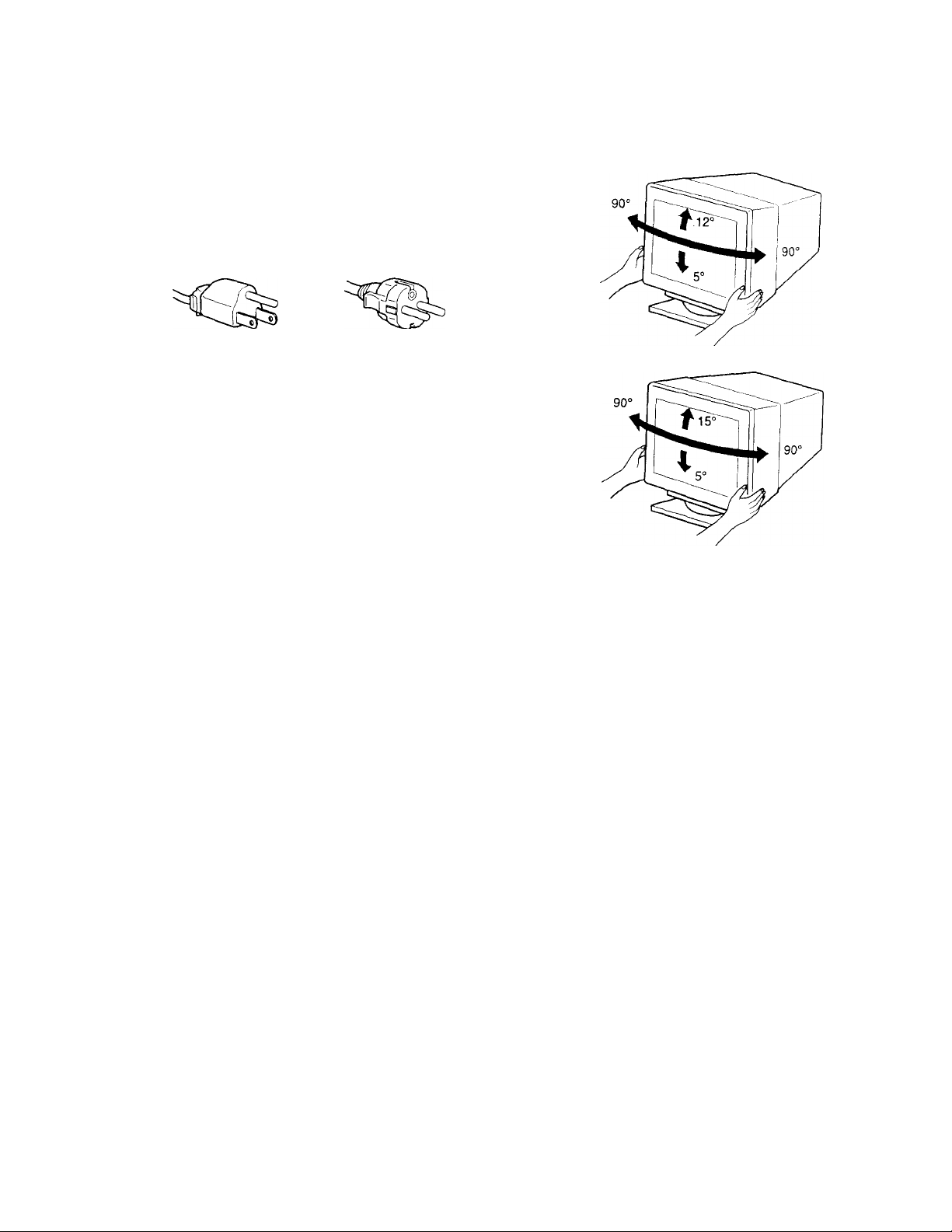
Use of the tilt-swivel
This monitor can be adjusted within the angles shown below. To
turn the monitor vertically or horizontally, hold it at the bottom
with both hands.
GDM-F400
GDM-F500
The equipment should be installed near an easily accessible
outlet
Installation
Do not install the monitor in the following places:
• on surfaces (rugs, blankets, etc.) or near materials (curtains,
draperies, etc.) that may block the ventilation holes
• near heat sources such as radiators or air ducts, or in a place
subject to direct sunlight
• in a place subject to severe temperature changes
• in a place subject to mechanical vibration or shock
• on an unstable surface
• near equipment which generates magnetism, such as a
transformer or high voltage power lines
• near or on an electrically charged metal surface
Maintenance
• Clean the screen with a soft cloth. If you use a glass cleaning
Uquid, do not use any type of cleaner containing an anti-static
solution or similar additive as this may scratch the screen’s
coating.
• Do not rub, touch, or tap the surface of the screen with sharp or
abrasive items such as a ballpoint pen or screwdriver. This type
of contact may result in a scratched picture tube.
• Clean the cabinet, panel and controls with a soft cloth lightly
moistened with a mild detergent solution. Do not use any type
of abrasive pad, scouring powder or solvent, such as alcohol or
benzene.
Transportation
When you transport this monitor for repair or shipment, use the
original carton and packing materials.
Page 5
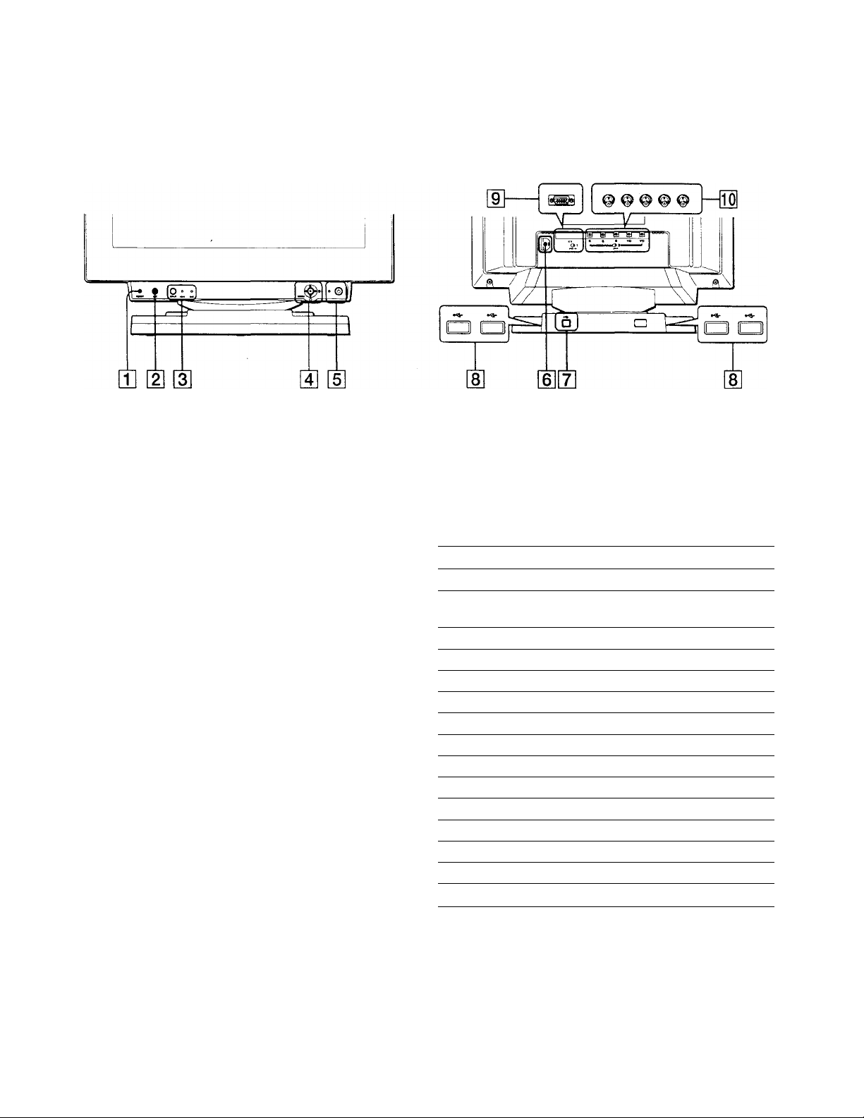
Identifying parts and controls
See the pages in parentheses for further details. GDM-F500 is
used for illustration purposes throughout this manual.
Front Rear
Q] RESET button (page 14)
This button resets the adjustments to the factory settings.
[2] ASC (auto sizing and centering) button (page 9)
This button automatically adjusts the size and centering of the
picture.
[3] INPUT button and HD 15/BNC indicators (page 9)
This button selects the HD 15 or BNC video input signal. The
input signal and corresponding input indicator change each
time you press this button.
[4] Joystick (page 11)
The joystick is used to display the menu and make
adjustments to the monitor, including brightness and contrast
adjustments.
[5] (!) (power) switch and indicator (pages 7,15,18)
This button turns the monitor on and off. The power indicator
lights up in green when the monitor is turned on, and either
flashes in green and orange, or hghts up in orange when the
monitor is in power saving mode.
[D AC IN connector (page 7)
This connector provides AC power to the monitor.
USB (universal serial bus) upstream connector (page 8)
Use this connector to link the monitor to a USB compliant
computer.
[8] USB (universal serial bus) downstream connectors
(page 8)
Use these connectors to link USB peripheral devices to the
monitor.
Video input 1 connector (HD15) (page 6)
TTiis connector inputs RGB video signals (0.700 Vp-p,
positive) and sync signals.
(D0@(D©
Pin No.
1
2
3
4
5
6
7
8
9
10
11
12
13
14
15
* DDC (Display Data Channel) is a standard of VESA.
01 Video Input 2 connector (BNC) (page 6)
This connector inputs RGB video signals (0.700 Vp-p,
positive) and sync signals.
Signal
Red
Green
(Composite Sync on Green)
Blue
ID (Ground)
DDC Ground*
Red Ground
Green Ground
Blue Ground
DDC + 5V*
Ground
ID (Ground)
Bi-Directional Data (SDA)*
H. Sync
V. Sync
Data Clock (SCL)*
Page 6
Setup
Before using your monitor, check that the following accessones
are included in your carton:
• Power cord (1)
• HD 15 video signal cable (1)
• USB cable (1)
• Macintosh adapter (1)
• Windows Monitor Information Disk (1)
• Warranty card (1)
• Notes on cleaning the screen's surface (1)
• This instruction manual (1)
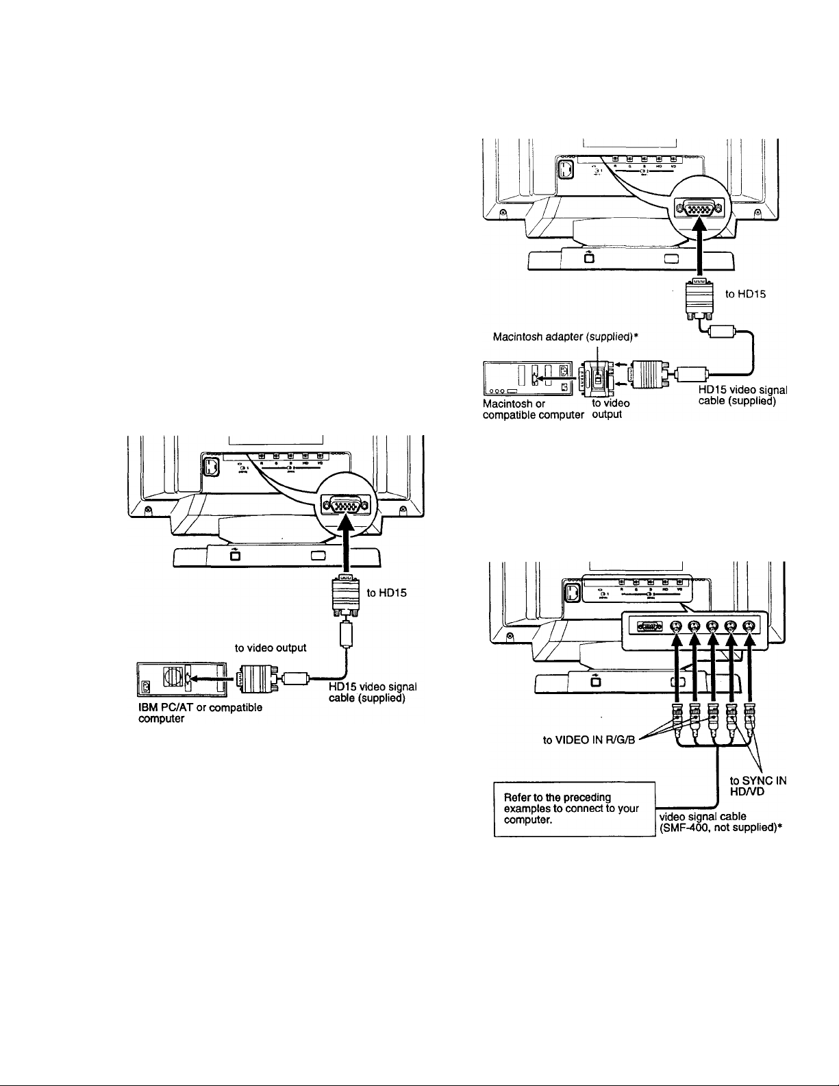
Step 1: Connect your monitor to
your computer
Turn off the monitor and computer before connecting.
■ Connecting to an IBM PC/AT or compatible
computer
■ Connecting to a Macintosh or compatible
computer
Use the supplied Macintosh adapter.
* Connect the supplied Macintosh adapter to the computer before •
connecting the cable. This adapter is compatible with Macintosh LC,
Performa, Quadra, Power Macintosh and Power Macintosh G3 series
computers. Macintosh II series and some older versions of PowerBook
models may need an adapter with micro switches (not supplied).
If your PC system Is not compatible with Plug & Play (DDC2AB
or 0DC2B+)
This monitor uses the No.9 pin in the video signal connector for Plug &
Play (DDC7AB or DDC2B+) compatibility. See page 5 for the location of
the No.9 pin.
• If your computer accepts the No.9 pin, use the supplied HD15 video
signal cable.
• If your computer does not accept the No.9 pin, please consult your
dealer for advice on obtaining an HD 15 adapter.
■ Connecting to the five BNC connectors
• Connect the cables from left to right in the following order Red-GreenBlue-HD-'VD.
Notes
• Do not touch the pins of the video cable connector as this might bend
the pins.
• Plug & Play (DDC) does not apply to the five BNC cormectors. If you
want to use Plug & Play, cormect your computer to the HD 15 connector
using the supplied video signal cable.
Page 7

step 2: Connect the power cord
With the monitor and computer switched off, first connect the
power cord to the monitor, then connect it to a power outlet.
Step 3:Turn on the monitor and
computer
First turn on the monitor, then turn on the computer.
O
The installation of your monitor is complete.
If necessary, use the monitor’s controls to adjust the picture.
If no picture appears on your screen
• Check that the monitor is correctly connected to the computer.
• If NO INPUT SIGNAL appears on the screen, try changing the
input signal (page 9), and confirm that your computer’s graphic
board is completely seated in the correct bus slot.
• If you are replacing an old monitor with this model and OUT
OF SCAN RANGE appears on the screen, reconnect the old
monitor. Then adjust the computer’s graphic board so that the
horizontal frequency is between 30-107 kHz (GDM-F4(X)) or
30-121 kHz (GDM-F500), and the vertical frequency is
between 48 - 160 Hz.
For more information about the on-screen messages, see “Trouble
symptoms and remedies” on page 16.
For customers using Windows 95/98
To maximize the potential of your monitor, install the new model
information file from the supplied Windows Monitor Information Disk
onto your PC.
This monitor complies with the “VESA DDC” Plug & Play standard. If
yourPC/graphics board compUes with DDC, select “Plug & Play Monitor
(VESA DDC)” or this monitor's model name as the monitor type in the
“Control Panel” of Windows 95/98. If your PC/graphics board has
difficulty communicating with this monitor, load the Windows Monitor
Information Disk and select this momtor’s model name as the monitor
type.
For customers using Windows NT4.0
Monitor semp m Windows NT4.0 is different from Wmdows 95/98 and
does not involve the selection of monitor type. Refer to the Wmdows
NT4.0 instruction manual for further details on adjusting the resolution,
refresh rate, and number of colors.
Adjusting the monitor’s resoiution and coior number
Adjust the momtor’s resolution and color number by referring to your
computer’s instruction manual. The color number may vary accordmg to
your computer or video board. The color palette setting and the actual
number of colors are as follows:
• High Color (16 bit)65,535 colors
• True Color (24 bit) —♦ about 16,77 million colors
In true color mode (24 bit), speed may be slower.
Page 8

Connecting Universal Serial Bus (USB) compliant peripherals
Selecting the on-screen menu language (LANG)
Your monitor has one upstream and four downstream USB
connectors. They provide a fast and easy way to connect USB
compliant peripheral devices (such as keyboards, mice, printers
and scanners) to your computer using a standardized USB cable.
To use your monitor as a hub for your peripheral devices, connect
the USBs as illustrated below.
to USB compliant
peripheral devices
to USB compliant
peripheral devices
1 Turn on the monitor and computer. 2 Connect your computer to the square upstream
connector using the supplied USB cable.
English, French, German, Spanish. Italian, and Japanese versions
of the on-screen menus ate available. The default setting is
English.
1 Press the joystick
See page 11 for more information on using the joystick.
ICOLOril center! screen
B Cÿ E 1
Move the joystick to highlight Q LANG and press the joystick again.
FRANÇAIS
DEUTSCH
ESPAÑOL
ITALIANO
For customers using Windows
If a message appears on your screen, follow the on-screen instructions
and select Generic USB Hub as the default setting.
3 Connect your USB compliant peripherai devices to
the rectanguiar downstream USB connectors.
Notes
• Not all computers and /or operating systems support USB
configurations. Check your computer’s instruction manual to see if you
can connect USB devices.
• In most cases, USB driver software needs to be installed on the host
computer. Refer to the peripheral device’s instruction manual for
further details.
• The monitor functions as a USB hub as long as the monitor is either
“on” or in power saving mode.
• If you connect a keyboard or mouse to the USB connectors and then
boot your computer for the first time, the peripheral devices may not
function. First connect the keyboard and mouse directly to the
computer and set up the USB comphant devices. Then connect them to
this monitor.
• Do not lean on the monitor when plugging in the USB cables. The
monitor may suddenly shift and cause injury.
3 Move the joystick up or down to select a language
and press the joystick again.
• ENGLISH
• FRANÇAIS: French
• DEUTSCH: German
• ESPAÑOL: Spanish
• ITALIANO: Italian
• a Japanese
To Close the menu
Press the joystick once to return to the main menu, and twice to return to
normal viewing. If no buttons are pressed, the menu closes automatically j
after about 30 seconds.
To reset to English
Press the RESET button while the LANGUAGE menu is displayed on the
screen.
8
Page 9

Selecting the input signal
You can connect two computers to this monitor using the HD 15
and BNC connectors. To switch between the two computers, use
the INPUT button.
Press the INPUT button.
The input signal and corresponding input indicator change each
time you press this button.
Notes
• If no signal is input to the selected connector, the monitor automatically
switches to the other connector.
• If you restart the computer you want to view, or that computer is in
power saving mode, the monitor may automatically switch to the other
connector’s signal. If this happens, manually select the desired signal
using the INPUT button.
Automatically sizing and centering the picture
You can easily adjust the picture to fill the screen by pressing the
ASC (auto sizing and centering) button.
Press the ASC button.
The picture automatically fills the screen.
ASC
Notes
• This function is intended for use with a computer running Windows or
similar graphic user interface software that provides a full-screen
picture. It may not work properly if the background color is dark or if
the input picture does not fill the screen to the edges (such as an MSDOS prompt).
• Pictures with an aspect ratio of 5:4 (resolution: 1280 x 1024, 1800 x
1440’*) are displayed at their actual resolution and do not fill the screen
to the edges.
• The screen may go blank for a few seconds when the ASC button is
pressed. This is not a malfunction.
* GDM-F500 only
Page 10

Customizing Your Monitor
You can make numerous adjustments to your monitor using the
on-screen menu.
Navigating the menu
Press the joystick to display the main MENU on your screen. See
page 11 for more information on using the joystick.
SS •-
GEOM
LANG
SIZE
Use the joystick to select one of the following menus.
m CENTER (page 11)
Select the CENTER menu to adjust
the picture’s centering.
ZOOM
a ».
OPTION
SCREEN (page 13)
Select the SCREEN menu to adjust
the picture's quality. You can adjust
the vertical and horizontal
convergence, landing, and moire
cancellation effect.
[7] LANG (page 8)
Select LANG to choose the on
screen menu’s language.
FRANÇAIS
DEUTSCH
ESPAÑOL
ITALIANO
OPTION (page 14)
Select OPTION to adjust the
monitor’s options. The options
include:
• degaussing the screen
• changing the on-screen menu
position
• changing the power saving delay
time
8
• locking the controls
] EXIT
Select EXIT to close the menu.
SIZE (page 11)
Select the SIZE menu to adjust the
picture’s horizontal and vertical
size.
GEOM (page 12)
Select the GEOM menu to adjust the
picture’s rotation and shape.
[4] ZOOM (page 12)
Select the ZOOM menu to enlarge
or reduce the picture.
COLOR (page 12)
Select the COLOR menu to adjust
the picture’s color temperature. You
can use this to match the monitor’s
colors to a printed picture’s colors.
ZOOM
5000K I 6500K
R BiASQ
G BIASa
B BIASO
R GAIN a
G GAIN a
B GAIND
H w m z
V HU
R
-----
n 26
■~~l 73
0
i
\
10
Page 11

■ Using the joystick
1 Select the menu you want to adjust.
Move the joystick up, down, left, or nght to highlight the
desired menu. Press the joystick to select the menu item.
Adjusting the brightness and contrast
Brightness and contrast adjustments are made using a separate
BRIGHTNESS/CONTRAST menu.
These settings are stored in memory for all input signals.
1 Move the joystick in any direction.
The BRIGHTNESS/CONTRAST menu appears on the
BRIGHTNESS/CONTRAST
2 Adjust the menu.
Move the joystick up, down, left, or tight to make the
adjustment.
3 Close the menu.
Press the joystick once to return to the main menu, and twice
to return to normal viewing. If no buttons are pressed, the
menu closes automatically after about 30 seconds.
■ Resetting the adjustments
Press the RESET button. See page 14 for more information on
resetting the adjustments.
RESET
a 26 a D 26 D
[ 80.0kHz/ 75Hz 1
the horizontal and vertical frequencies of the
current input signal
2 Move the Joystick up or down to adjust the
brightness (fO;), and left or right to adjust the
contrast (3).
The menu automatically disappears after about 3 seconds.
Adjusting the centering of the
picture (CENTER)
This setting is stored in memory for the current input signal.
1 Press the Joystick.
The main MENU appears on the screen.
2 Move the Joystick to highlight [3 CENTER and
press the Joystick again.
The CENTER menu appears on the screen.
3 Move the Joystick up or down to adjust the vertical
centering, and left or right to adjust the horizontal
centering.
Adjusting the size of the picture
(SIZE)
This setting is stored in memory for the current input signal.
1 Press the Joystick.
The main MENU appears on the screen.
2 Move the Joystick to highlight Q SIZE and press the
Joystick again.
The SIZE menu appears on the screen.
3 Move the Joystick up or down to adjust the vertical
size, and left or right to adjust the horizontal size.
11
Page 12

Adjusting the shape of the picture
Adjusting the color of the picture
(GEOM)
The GEOM settings allow you to adjust the rotation and shape of
the picture.
The rotation setting is stored in memory for all input signals. All
other settings are stored in memory for the current input signal. •
1 Press the joystick.
The main MENU appears on the screen.
2 Move the joystick to highlight O GEOM and press
the joystick again.
The GEOMETRY menu appears on the screen.
3 First move the joystick up or down to select the
desired adjustment item. Then move the joystick left
or right to make the adjustment.
Select
O ROTATION
n PINCUSHION
D PIN BALANCE
O KEYSTONE
O KEY BALANCE
To
rotate the picture
expand or contract the picture sides
shift the picture sides to the left or right
adjust the picture width at the top of
the screen
shift the picture to the left or right at
the top of the screen
(COLOR)
The COLOR settings allow you to adjust the picture’s color i
temperature by changing the color level of the white color field, f
Colors appear reddish if the temperature is low, and bluish if the ’
temperature is high. This adjustment is useful for matching the
monitor’s colors to a printed picture’s colors.
This setting is stored in memory for all input signals. .
1 Press the joystick.
The main MENU appears on the screen.
2 Move the joystick to highlight g] COLOR and press ,
the joystick again.
The COLOR menu appears on the screen.
3 Move the joystick left or right to select a color
temperature.
The preset color temperatures are 5000K, 6500K, and 9300K. ;
Since the default setting is 9300K, the whites will change
from a bluish hue to a reddish hue as the temperature is
lowered to 6500K and 5000K.
4 If necessary, fine tune the color temperature. |
First move the joystick up or down to select the desired *
adjustment item. Then move the joystick left or right to make
the adjustment. "
f -
Enlarging or reducing the picture (ZOOM)
This setting is stored in memory for the current input signal.
1 Press the joystick.
The main MENU appears on the screen.
2 Move the joystick to highlight gs ZOOM and press
the joystick again.
The ZOOM menu appears on the screen.
3 Move the joystick left or right to enlarge or reduce
the picture.
Note
Adjustment stops when either the horizontal or vertical size reaches its
maximum or minimum value.
Q] Adjusting the BIAS (black level)
This changes the brightness of both the dark and light
areas of an image.
[2] Adjusting the GAIN (white level)
This changes the contrast of just the light areas of an
image.
You can adjust the R(Red), G(Green), and B(Blue)
component of the input signal when making changes to items
[Iland[2].
If you fine tune the color temperature, the new color settings
are stored in memory for each of the three color temperatures
and item [2 of the on-screen menu changes as follows;
• [5000K]-»m
• [6500K]-<■ [2]
• [9300K]-»[3j
12
Page 13

Adjusting the quality of the picture (SCREEN)
The SCREEN settings allow you to adjust the quality of the
picture by controlling the convergence, moire, and landing.
• If you see red or blue shadows around letters or lines, adjust the
convergence.
• If elliptical or wavy patterns appear on the screen, cancel the
moire.
• If the color is irregular at the comers of the screen, adjust the
landing.
The CANCEL MOIRE and MOIRE ADJUST settings ate stored
in memory for the current input signal. All other settings are
stored in memory for all input signals.
1 Press the joystick.
The main MENU appears on the screen.
2 Move the joystick to highlight dn] SCREEN and
press the joystick again.
The SCREEN menu appears on the screen.
Select
В
CANCEL MOIRE*
И ADJ
MOIRE ADJUST
Moire is a type of natural interference which produces soft, wavy lines
on your screen. It may appear due to interference between the pattern
of the picture on the screen and the phosphor pitch pattern of the
monitor.
Example of moire
To
turn the moue cancellation function
ON or OFF
O ADJ (MOIRE ADJUST) appears
in the menu when you select ON
adjust the degree of moire
cancellation until the moire is at a
minimum
3 First move the joystick up or down to select the
desired adjustment item. Then move the joystick left
or right to make the adjustment.
Select
QD
To
horizontally shift red or blue shadows
H CONVERGENCE
Щ }
vertically shift red or blue shadows
V CONVERGENCE
© TOP
V CONVER TOP
© ВОТ
V CONVER ВОТ
a
LANDING
□ ADJ
LANDING ADJUST
vertically shift red or blue shadows at
the top of the screen
vertically shift red or blue shadows at
the bottom of the screen
select one of the four comers of the
screen
□ :top left □ Top right
O ibottom left Q ;bottom right
reduce any irregularities in the color
of the comer selected in LANDING
to a minimum
Note
The picture may become fuzzy when CANCEL MOIRE is set to ON.
Page 14

Additional settings (OPTION)
Resetting the adjustments
You can manually degauss (demagnetize) the monitor, change the
menu position, set the power saving delay time, and lock the
controls.
1 Press the joystick.
The main MENU appears on the screen.
2 Move the joystick to highlight ^ OPTION and press
the joystick again.
The OPTION menu appears on the screen.
3 Move the joystick to highlight the desired
adjustment item.
Adjust the selected item according to the following
instructions.
Degaussing the screen
The monitor is automatically demagnetized when the power is
turned on.
To manually degauss the monitor, first move the
joystick up or down to select (MANUAL DEGAUSS).
Then move the joystick to the right.
The screen is degaussed for alxmt 3 seconds. If a second degauss
cycle is needed, allow a minimum interval of 20 minutes for the
best result.
This monitor has the following three reset methods. Use the f
RESET button to reset the adjustments. v
RESET
Resetting a single adjustment item i
Use the joystick to select the adjustment item you want to resefr
and press the RESET button. '5
Resetting all of the adjustment data for the I
current input signal
Press the RESET button when no menu is displayed on the screei
Note that the following items are not reset by this method:
• on-screen menu language (page 8)
• on-screen menu position (page 14)
• power saving delay time (page 14)
• control lock (page 14)
f
Resetting all of the adjustment data for all input
signals
Press and hold the reset button for more than two seconds
I
Changing the menu’s position.
Change the menu’s position if it is blocking an image on the
screen.
To change the menu’s on-screen position, first move
the joystick up or down to select S (OSD H POSITION)
for horizontal adjustment, or (OSD V POSITION) for
vertical adjustment. Then move the joystick to the left
or right to shift the on-screen menu.
Changing the power saving delay time.
To adjust the time it takes to enter the power saving
mode, first move the joystick up or down to select @
(PWR SAVE DELAY). Then move the joystick to the left
or right to select the desired time.
If you select OFF, the monitor does not enter power saving mode.
See page 15 for more information about the monitor’s power
saving capabilities.
Locking the controls.
To protect adjustment data by locking the controls, first
move the joystick up or down to select On (CONTROL
LOCK). Then move the joystick to the right to select
LOCK.
Only the (!) (power) switch, EXIT, and On (CONTROL LOCK)
of the S OPTION menu will operate. If any other items are
selected, the On mark appears on the screen.
Note
The RESET button does not function when On (CONTROL LOC^
is set to LOCK.
To cancel the control lock
Repeat the procedure above and set On (CONTROL LOCK) to
UNLOCK.
14
Page 15
Technical Features
Preset and user modes
Troubleshooting
Before contacting technical support, refer to this section.
When the monitor receives an input signal, it automatically
matches the signal to one of the factory preset modes stored in the
monitor’s memory to provide a high quality picture at the center
of the screen. (See page i for a list of the factory preset modes.)
For input signals that do not match one of the factory preset
modes, the digital Multiscan technology of this monitor ensures
that a clear picture appears on the screen for any timing in the
monitor’s frequency range (horizontal; 30 - 107 kHz (GDMF400) or 30 - 121 kHz (GDM-F500), vertical: 48- 160 Hz). If
the picture is adjusted, the adjustment data is stored as a user
mode and automatically recalled whenever the same input signal
is received.
Note for Windows users
For Windows users, check your video board manual or the utility
program which comes with your graphic board and select the
highest available refresh rate to mattimize monitor performance.
Power saving function
This monitor meets the power-saving guidelines set by VESA,
ENERGY STAR, and NUTEK. If the monitor is connected to a
computer or video graphics board that is DPMS (Display Power
Management Signaling) compliant, the monitor will
automatically reduce power consumption in three stages as shown
below.
If thin lines appear on your screen
(damper wires)
The lines you are experiencing on your screen are normal for the
Trinitron monitor and are not a malfunction. These are shadows
from the damper wires used to stabilize the aperture grille and are
most noticeable when the screen’s background is light (usually
white). The aperture grille is the essential element that makes a
Trinitron picture tube unique by allowing more light to reach the
screen, resulting in a brighter, more detailed picture.
Damper wires
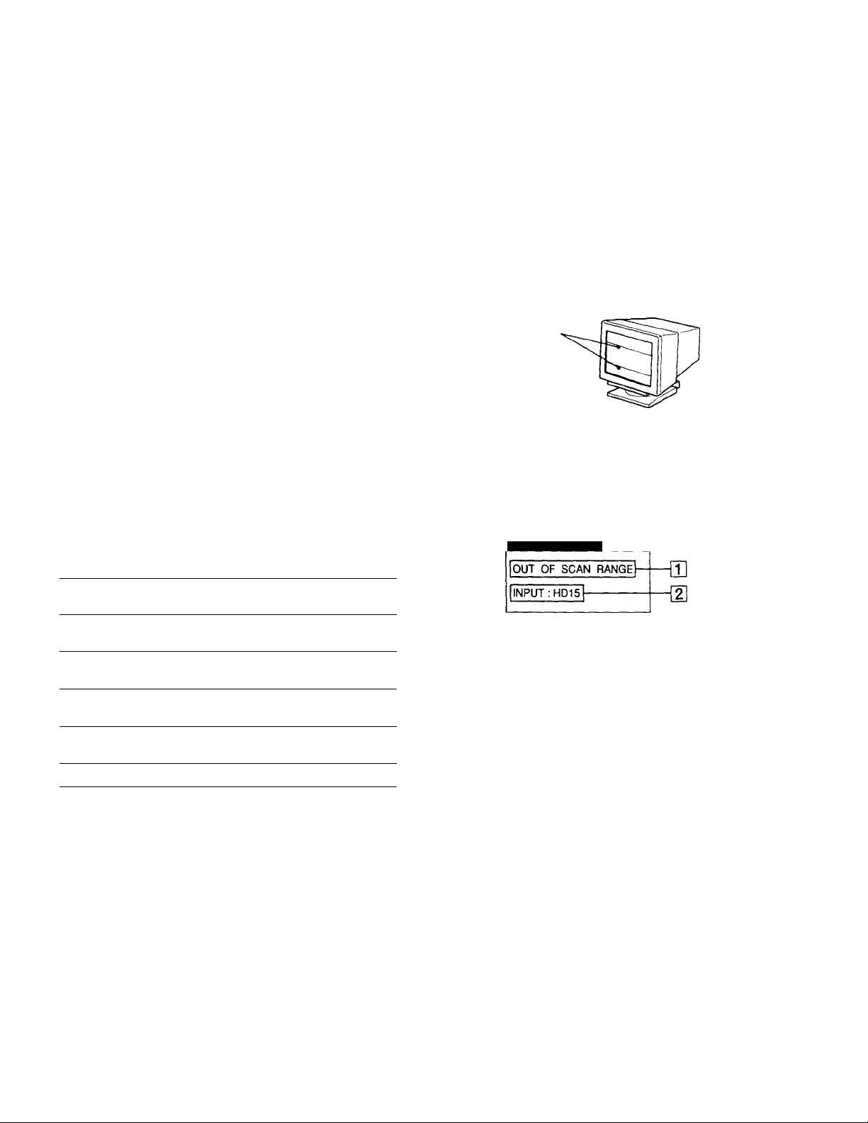
On-screen messages
If there is something wrong with the input signal, one of the
following messages appears on the screen. To solve the problem,
see ‘Trouble symptoms and remedies” on page 16.
O INFORMATION
Power mode Power
consumption*
normal
operation
1 standby <100’W(GDM-F500)
2 suspend
3 active off**
power off OW off
* Figures reflect power consumption when no USB compatible
peripherals are connected to the monitor.
**When your computer enters the “active off’ mode, the input signal is
cut and NO INPUT SIGNAL appears on the screen. After the time set
in “Changing the power saving delay time.” (page 14) has elapsed, the
monitor enters the power saving mode.
To change the power saving delay time
See page 14,
5 160 W (GDM-F500)
< 140W(GDM-F400)
<80’W(GDM-F400)
< 15 W (GDM-F500)
< 10 W (GDM-F400)
< 1 'W (GDM-F500)
< 3 W (GDM-F400)
(1) (power)
indicator
green
green and orange
alternate
green and orange
alternate
orange
Q] The input signal condition
OUT OF SCAN RANGE
indicates that the input signal is not supported by the
monitor’s specifications.
NO INPUT SIGNAL
indicates that no signal is input, or that no signal is input from
the selected connector (HD 15 or BNC).
d] The connector indicator
This message indicates which coimector is receiving the
wrong signal. If there is something wrong with the signal
from both connectors, HD 15 and BNC are displayed
alternately.
15
Page 16

Trouble symptoms and remedies
If the problem is caused by the connected computer or other equipment, please refer to the connected equipment’s instruction manual.
Use the self-diagnosis function (page 18) if the following recommendations do not resolve the problem.
Symptom
No picture
If the cl) (power) indicator is not lit
If the NO INPUT SIGNAL message
appears on the screen, or if the (1)
(power) indicator is either orange or
alternating between green and
orange
If the OUT OF SCAN RANGE
message appears on the screen
If no message is displayed and the (!)
(power) indicator is green or flashing
orange
If using Windows 95/98
If using a Macintosh system
Picture flickers, bounces,
oscillates, or is scrambled
Check these items
Check that the power cord is properly connected.
Check that the (1) (power) switch is in the “on” position.
Check that the video signal cable is properly connected and all plugs are firmly seated i
their sockets. If you are using the five BNC connectors, connect them in the correct ord^
(from left to right: Red-Green-Blue-HD-'VD) (page 6).
Check that the input select setting is correct (page 9).
Check that the HD15 video input connector’s pins are not bent or pushed in.
• The computer is in power saving mode. Try pressing any key on the computer keyboardi;
• Check that the computer’s power is “on.” t
• Check that the graphic board is completely seated in the proper bus slot. i
■Problems caused by the connected computer or other equipment
• Check that the video frequency range is within that specified for the monitor. If you [
replaced an old monitor with this monitor, reconnect the old monitor and adjust the
frequency range to the following.
Horizontal: 30 - 107 kHz (GDM-F400), 30 - 121 kHz (GDM-F500)
Vertical: 48 - 160 Hz ‘
• Use the Self-diagnosis function (page 18).
• If you replaced an old monitor with this monitor, reconnect the old monitor and do the
following. Install the Windows Monitor Information Disk (page 7) and select this monitr
(“GDM-F400” or “GDM-F5(X3”) from among the Sony monitors in the Windows 95/98
monitor selection screen. If you choose to select “Plug and Play,” connect the monitor t№
the computer with the HD15 video signal cable. You cannot use the five BNC connecto®
• Check that the Macintosh adapter and the video signal cable are properly coimected *
(page 6). 1
Isolate and eliminate any potential sources of electric or magnetic fields such as other
monitors, laser printers, electric fans, fluorescent lighting, or televisions.
Move the monitor away from power lines or place a magnetic shield near the monitor.
Try plugging the monitor into a different AC outlet, preferably on a different circuit
Try turning the monitor 90° to the left or right.
Picture is fuzzy
16
IProblems caused by the connected computer or other equipment
Check your graphics board manual for the proper monitor setting.
Confirm that the graphics mode (VESA, Macintosh 21" Color, etc.) and the frequency oj
the input signal are supported by this monitor (page i). Even if the frequency is within i
proper range, some video boards may have a sync pulse that is too narrow for the monitc
to sync correctly.
Adjust the computer’s refresh rate (vertical frequency) to obtain the best possible pict
Adjust the brightness and contrast (page 11).
Degauss the monitor* (page 14).
If CANCEL MOIRE is ON, the picture may become fuzzy. Decrease the moire
cancellation effect or set CANCEL MOIRE to OFF (page 13).
Page 17

Symptom Check these items
Picture is ghosting • Eliminate the use of video cable extensions and/or video switch boxes.
• Check that all plugs are firmly seated in their sockets.
Picture is not centered or sized
properiy
Edges of the image are curved
Wavy or elliptical pattern (moire)
• Press the ASC button (page 9).
• Adjust the size (page 11) or centering (page 11). Note that some video modes do not fill
the screen to the edges.
• Adjust the geometry (page 12).
• Cancel the moire (page 13).
is visible
■Problems caused by the connected computer or other equipment
• Change your desktop pattern.
Color is not uniform • Degauss the monitor’* (page 14). If you place equipment that generates a magnetic field,
such as a speaker, near the monitor, or if you change the direction the monitor faces, color
may lose muformity.
• Adjust the landing (page 13).
White does not look white
Letters and lines show red or blue
• Adjust the color temperature (page 12).
• Check that the five BNC connectors are connected in the correct order (from left to right:
Red-Green-Blue-HD-VD) (page 6).
• Adjust the convergence (page 13).
shadows at the edges
Monitor buttons do not operate • If the control lock is set to LOCK, set it to UNLOCK (page 14).
USB peripherals do not function
• Check that the appropriate USB connectors are securely connected (page 8).
• Check that the (!) (power) switch is in the “on” position.
■Problems caused by the connected computer or other equipment
• Check that the power of any self-powered USB compliant peripheral devices is “on."
• Install the latest version of the device driver on your computer. Contact your device’s
manufacturer for information about the appropriate device driver.
• If your USB compliant keyboard or mouse does not function, connect them directly to
your computer, reboot your computer, and make any necessary adjustments to the USB
settings. Then reconnect the keyboard or mouse to the monitor.
• For customers using Windows 95
1. Right-click on My Computer and select Properties.
2. Click on the Device Manager tab. Scroll down and select Universal Serial Bus
Controller.
■^If Universal Serial Bus Controller does not appear, you need to load a USB
supplement disk. Contact your computer’s manufacturer for more information about
obtaining a USB supplement disk.
3. Select Generic USB Device from the USB controller list and click on Properties.
4. If there is a check in the box next to “Disable in this hardware profile,” remove the
check.
5. Click on Refresh.
A hum is heard right after the
power is turned on
• This is the sound of the auto-degauss cycle. When the power is turned on, the monitor is
automatically degaussed for three seconds.
* If a second degauss cycle is needed, allow a minimum interval of 20 minutes for the best result. A humming noise may be heard, but this is not a
malfunction.
Displaying this monitor’s name, serial number, and date of manufacture.
While the monitor is receiving a video signal, press and hold the
joystick for more than three seconds to display this monitor’s
information box.
Example
O INFORMATION
model: GDM-F500
SER NO'. 1234567
MANUFACTURED : 1996-52
If the problem persists, call your authorized Sony dealer and give
the following information.
• Model name: GDM-F400, GDM-F500
• Serial number
• Name and specifications of your computer and graphics board.
Page 18

Self-diagnosis function
This monitor is equipped with a self-diagnosis function. If there is
a problem with your monitor or computerfs), the screen will go
blank and the (1) (power) indicator will either light up green or
flash orange. If the (1) (power) mdicator is lit in orange, the
computer is in power saving mode. Try pressing any key on the
keyboard.
O (power) indicator
if the (!) (power) indicator is green
1 Remove any plugs from the video input 1 and 2
connectors, or turn off the connected computer(s).
2 Press the (!) (power) button to turn the monitor off
and on.
3 Move the joystick to the right for 2 seconds before
the monitor enters power saving mode.
Specifications
GDM-F400
CRT
Viewable image size
Resolution
Standard image area
Deflection frequency*
AC input voltage/current
Power consumption
Dimensions
Mass
Plug and Play
Supplied accessories
0.22 mm aperture grille pitch
19 inches measured diagonally
90-degree deflection
FD Trinitron
Approx. 364,8 X 273,6 mm (w/h)
(14 Vs X 10 Vs inches)
18.0" viewing image
Horizontal; Max. 1600 dots
Vertical; Max. 1200 lines
Approx. 352 X 264 mm (w/h)
(13 Vs X 10 '/2 inches)
or
Approx. 330 X 264 mm (w/h)
(13 X 10 '/2 inches)
Horizontal; 30 to 107 kHz
Vertical; 48 to 160 Hz
100 to 240 V, 50-60 Hz, 1.8-l.OA
Max. 140 W (with no USB devices
connected)
Approx. 444 X 476 x 455 nun (w/h/d)
(17 '/2 X 18 V4 X 18 inches)
Approx. 28 kg (61 lb 12 oz)
DDCl/DDC2B/DDC2Bi/DDC2B+
See page 6
If all four color bars appear (white, red, green, blue), the monitor
is working properly. Reconnect the video input cables and check
the condition of your computerfs).
If the color bars do not appear, there is a potential monitor failure.
Inform your authorized Sony dealer of the monitor’s condition.
If the (!) (power) indicator is flashing orange
Press the (!) (power) button to turn the monitor off and
on.
If the (!) (power) indicator lights up green, the monitor is working
properly.
If the (!) (power) indicator is still flashing, there is a potential
monitor failure. Count the number of seconds between orange
flashes of the (!) (power) indicator and inform your authorized
Sony dealer of the monitor’s condition. Be sure to note the model
name and serial number of your monitor. Also note the make and
model of your computer and video board.
GDM-F500
CRT
Viewable image size
Resolution
Standard image area
Deflection frequency*“
AC input voltage/current
Power consumption
Dimensions
Mass
Plug and Play
Supplied accessories
* Recommended horizontal and vertical timing condition
• Horizontal sync width duty should be more than 4.8% of total
horizontal time or 0.8 ps, whichever is larger.
• Horizontal blanking width should be more than 2.5 psec.
• Vertical blanking width should be more than 450 psec.
0.22 mm aperture grille pitch
21 inches measured diagonally
90-degree deflection
FD Trinitron
Approx. 403.8 X 302.2 mm (w/h)
(16 X 12 inches)
19.8" viewing image
Horizontal: Max. 1800 dots
Vertical: Max. 1440 lines
Approx. 388 X 291 mm (w/h)
(15 Vs X 11 */2 inches)
or
Approx. 364 X 291 nun (w/h)
(14 Vs X 11 '/2 inches)
Horizontal: 30 to 121 kHz
Vertical: 48 to 160 Hz
100 to 240 V, 50 - 60 Hz, 2.0 - 1.0 A
Max. 160 W (with no USB devices
connected)
Approx. 502 X 511 X 486.3 mm (w/h/d)
(19 Vs X 20 Vs X 19 '/4 inches)
Approx. 34 kg (74 lb 15 oz)
DDC1DDC2BDDC2ABDDC2B+
See page 6
18
Design and specifications are subject to change without notice.
Page 19

Appendix
Preset mode timing table
No. Resolution Horizontal Vertical Graphics
(dots X lines) Frequency Frequency Mode
1 640 X 350 31.5 kHz
2 640 X 480
3
640 x 480 37.3 kHz 75 Hz EVGA
4 640 x 480
5 720 x 400
6 720 X 400 37.9 kHz
7 800x600 37.9 kHz
8
800x600 46.9 kHz 75 Hz ESVGA
9 800x600 53.7 kHz 85 Hz
10
832 X 624 49.7 kHz
1024 X 768
11
12 1024 X 768
1024 X 768
13
14
1024x768
1024 X 768
15
16 1152x864
17
1152x870
18 1280 X 960
19 1280 X 960
1280X1024
20
21 1280 X 1024
22
1280 X1024
23
1600 X 1200 75.0 kHz 60 Hz
24
1600 X 1200
25 1600 X 1200 87.5 kHz
26
1600X1200 93.8 kHz
27 1600 X 1200
I" 1800 X 1350
28’
29* 1800 X 1440
* GDM-F500 only
31.5 kHz 60 Hz VGA-G
43.3 kHz 85 Hz VESA
31.5 kHz 70 Hz
48.4 kHz 60 Hz VESA
56.5 kHz
60.0 kHz 75 Hz EUVGA
60.2 kHz 75 Hz Macintosh 19"
68.7 kHz 85 Hz
67.5 kHz
68.7 kHz 75 Hz Macintosh 21"
60.0 kHz
85.9 kHz
64.0 kHz
80.0 kHz 75 Hz
91.1kHz 85 Hz VESA
81.3 kHz 65 Hz
106.3 kHz
<121.0 kHz 85 Hz
< 121.0 kHz 80 Hz VESA GTE
70 Hz MCGA
85 Hz VESA
60 Hz SVGA
75 Hz Macintosh 16"
70 Hz VESA
75 Hz
60 Hz VESA
85 Hz VESA
60 Hz VESA
70 Hz VESA
75 Hz VESA
85 Hz VESA
VGA-Text
VESA
Color
Color
VESA
VESA
Color
VESA
VESA
VESA
VESAGTF
TCO’95 Eco-document
■ Congratulations!
You have just purchased a TCO'95 approved and labelled
product! Your choice has provided you with a product
developed for professional use. Your purchase has also
contributed to reducing the burden on the environment and
also, to the further development of environmentally
adapted electronics products.
■ Why do we have environmentally labelled
computers?
In many countries, environmental labelling has become an
established method for encouraging the adaptation of goods and
services to the environment. The main problem, as far as
computers and other electronics equipment are concerned, is that
environmentally harmful substances are used both in the products
and during the manufacturing. Since it has not been possible for
the majority of electronics equipment to be recycled in a
satisfactory way, most of these potentially damaging substances
sooner or later enter Nature.
There are also other characteristics of a computer, such as energy
consumption levels, that are important from the viewpoints of
both the work (internal) and natural (external) environments.
Since all methods of conventional electricity generation have a
negative effect on the environment (acidic and climateinfluencing emissions, radioactive waste, etc.), it is vital to
conserve energy. Electronics equipment in offices consume an
enormous amount of energy since they are often left running
continuously.
■ What does labelling involve?
This product meets the requirements for the TCO’95 scheme
which provides for international and environmental labelling of
personal computers. The labelling scheme was developed as a
joint effort by the TCO (The Swedish Confederation of
fhofessional Employees), Naturskyddsforeningen (The Swedish
Society for Nature Conservation) and NUTEK (The National
Board for Industrial and Technical Development in Sweden).
The requirements cover a wide range of issues: environment,
ergonomics, usability, emission of electrical and magnetic fields,
energy consumption and electrical and fire safety.
(co n tin u ed)
I
Page 20

The environmental demands concern restrictions on the presence
and use of heavy metals, brormnated and chlorinated flame
retardants, CFCs (fréons) and chlorinated solvents, among other
things. The product must be prepared for recycling and the
manufacturer ts obliged to have an envu-onmental plan which
must be adhered to in each country where the company
implements its operational policy.
The energy requirements include a demand that the computer and/
or display, after a certain period of inactivity, shall reduce its
power consumption to a lower level in one or more stages. The
length of time to reactivate the computer shall be reasonable for
the user.
Labelled products must meet strict environmental demands, for
example, in respect of the reduction of electric and magnetic
fields, physical and visual ergonomics and good usability.
Cadmium**
Cadmium is present in rechargeable batteries and in the
colourgenerating layers of certain computer displays. Cadmium
damages the nervous system and is toxic in high doses.
TCO’95 requirement states that battenes may not contain more
than 25 ppm (parts per million) of cadmium. The colour
generating layers of display screens must not contain any
cadmium.
Mercury**
Mercury is sometimes found in batteries, relays and switches.
Mercury damages the nervous system and is toxic in high doses.
TCO’95 requirement states that batteries may not contain more
than 25 ppm (parts per million) of mercury. It also demands that
no mercury is present in any of the electrical or electronics
components concerned with the display unit.
On this page, you will fmd a brief summary of the environmental
requirements met by this product. The complete environmental
criteria document may be ordered from:
TOO Development Unit
S-114 94 Stockholm
Sweden
Fax: +46 8 782 92 07
Email (Internet): development@tco.se
Current information regarding TCO’95 approved and labelled
products may also be obtained via the Internet, using the
address:
http;//www.tco-info,com/
TCO’95 is a co-operative project between TCO (The Swedish
Confederation of Professional Employees),
Naturskyddsforeningen (The Swedish Society for Nature
Conservation) and NÜTEK (The National Board for Industrial
and Technical Development in Sweden),
■ Environmental Requirements Brominated flame retardants
Brominated flame retardants are present in printed circuit boards,
cables, wires, casings and housings. In turn, they delay the spread
of fire. Up to thirty percent of the plastic in a computer casing can
consist of flame retardant substances. These are related to another
group of environmental toxins, PCBs, which are suspected to give
rise to similar harm, including reproductive damage in fisheating
birds and mammals, due to the bio-accumulative* processes.
Flame retardants have been found in human blood and researchers
fear that disturbances in foetus development may occur.
TCO’95 demand requires that plastic components weighing more
than 25 grams must not contain organically bound chlorine and
bromine.
CFCs (freons)
CFCs (freons) are sometimes used for washing printed circuit
boards and in the manufacturing of expanded foam for packaging.
CFCs break down ozone and thereby damage the ozone layer in
the stratosphere, causing increased reception on Earth of
ultraviolet light with consequent increased risks of skin cancer
(mahgnant melanoma).
The relevant TCO’95 requirement: Neither CFCs nor HCFCs
may be used during the manufacturing of the product or its
packaging.
• Bio-accumulative is defined as substances which accumulate within
living organisms
**Lcad, Cadmium and Mercury are heavy metals which are Bio-
accumulative.
Lead**
Lead can be found in picture tubes, display screens, solders and
capacitors. Lead damages the nervous system and in higher doses,
causes lead poisoning.
TCO’95 requirement permits the inclusion of lead since no
replacement has yet been developed.
Sony Corporation
SonywHline http://www.wor1d.sony.com/
Printed on recycled paper
Printed in Japan
 Loading...