

Page 1

3-759-203-21 (1)
Multiscan® Graphic Display
GDM-2000TC
Operating Instructions
Mode d’emploi
________
1994 by Sony Corporation
Page 2

Owner's Record
Tin- model tind seriiil numbers me located at the rear ol the
unit. Record the serial number in the space provided Ix'low
Refer to these numbers whenever vou c.ill upon vour dealer
regarding this product.
Model No. GOM-2000TC Serial No.
WARNING
NOTICE
I his notice IS applicable tor USACanada onl\'.
II shipped to USA/Canada, install only a Lll I.ISTI’.D/
eSA I.ABIfl.I.HD [.rower siqiph' cord meeting the
lollowing specifications:
SI’lfClI'ICATlONS
Plug Type Nema-Plug 3-13p
Gord l’vpe SV'F or SJ F, minimum 3x18
AWG
l.ength
Rating
Maximum 13 feet
Minimum 7 A, 125 V
To prex'ent fire or shock hazard, do not expose the unit to
rain or moisture.
Dangerously high voltages are present inside the set. Do not
open the cabinet. Refer servicing to qualified personnel
only.
This equipment has been tested and found to compì)' \s ith
the limits for a Class B digital device, pursuant to Part 13 of
the FCC Rules. These limits are designed to provide
reasonable protection against harmful interference in a
residential installation. This equipment generates, uses, and
can radiate radio frequency energy and, if not installed and
used in accordance with the instructions, mav cause
harmful interference to radio communications. 1 knve\ er,
there is no guarantee that interference will not occur in a
particular installation. If this equipment does cause harmful
interference to radio or television reception, which can be
determined bv turning the equipment off and on, the user is
encouraged to trv to correct the interference bv one or more
of the following measures:
- Reorient or relocate the receiving antenna.
- Increase the separation between the equipment and
receiver.
- Connect the equipment into an outlet on a circuit different
from thaf to which the receiver is connected.
- Consult the dealer or an experienced radio/TV technician
for help.
.You are cautioned that any changes or modifications not
expressly approved in this manual could void your
authority to operate this equipment.
NOTICE
Cette notice s'applique aux Rtnts-Unis et au Canada
U niquement.
Si cet appareil est exporté aux Etats-Unis ou au Canada,
utiliser le cordon d'alimentation portant la mention UL
LISTED/CSA LABELLED et remplissant les conditions
suivantes:
SPECIFICATIONS
Type de fiche Fiche Nema 3-15 broches
Cordon Type SVT ou S|T, minimum .3x18
AWG
Longuer Maximum 13 pieds
Tension Minimum 7 A, 123 V
For the customers in Canada
This apparatus complies with the Class B Limits for radio
noise emissions set out in Radio Interference Regulations.
Pour les utilisateurs au Canada
Cet appareil est conforme aux normes Classe B pour
bruits radioélectriques, spécifiés dans le Règlement sur le
brouillage radioélectrique.
Page 3
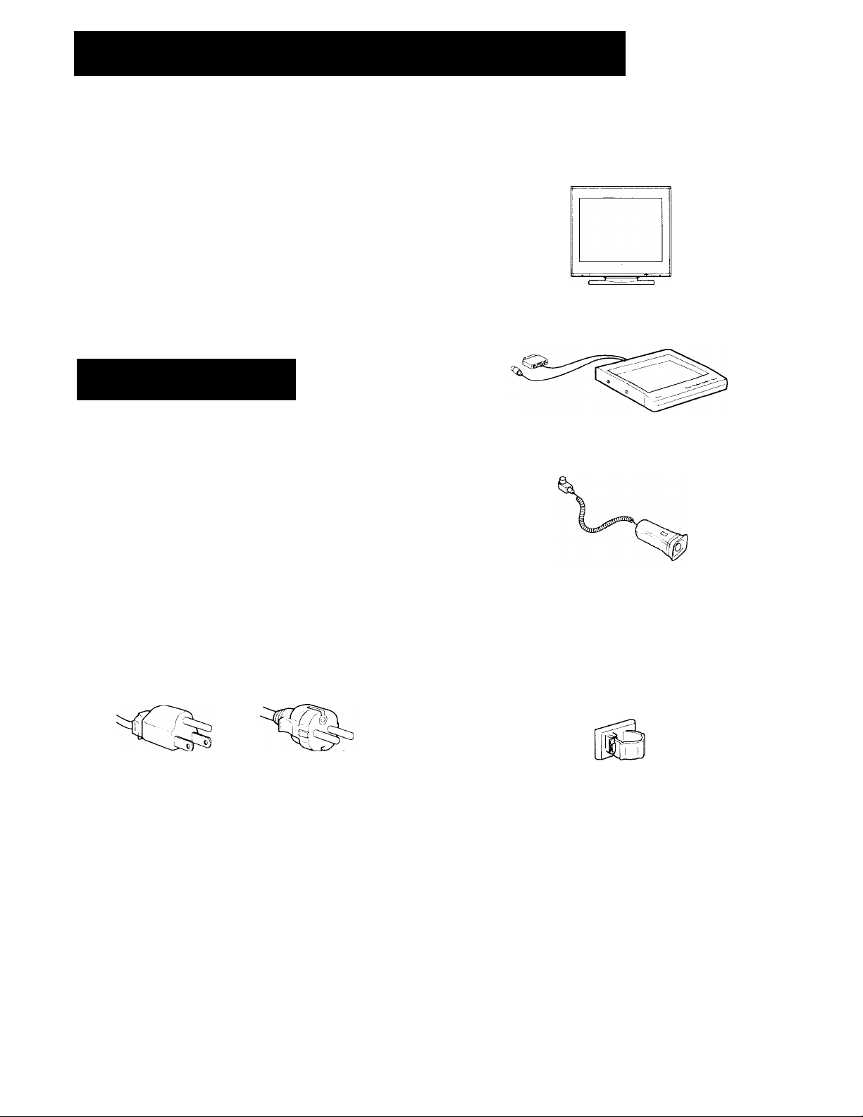
Table of Contents H Checklist
Checklist .................................................................................................>
Setting up................................................................................................4
Using vour monitor
Function of controls................................................................................h
Adjustments............................................................................................7
Using on-screen menus........................................................................IS
Operating through menus...................................................................4
COLOR TEMPHRAI'URF: fine adjustment
Uniformity adjustment
Power saving function
Specifications .......................................................................................12
Use of the tilt-swi\'el..............................................................................12
Troubleshooting ...................................................................................12
................................................................................
....................................
.....................................................................
...................
......................................................
10
10
12
Precautions
Installation
I Pre\'ent internal heat build-up by allowing adequate air
circulation. Do ncit place the unit on surfaces (rugs,
blankets, etc.) nor near materials (curtains, draperies) that
may block the ventilation holes.
' Do not install the unit near heat sources such as radiators
or air ducts, nor in a place subject to direct sunlight,
excessive dust, mechanical vibration or shock.
• Do not place the unit near equipment which generates
magnetism, such as a converter or high voltage power
lines.
Ik-fore using this monitor, please make sure that the
lollowing items are included in your package:
4
CnM-20()0TC Monitor (1)
CDM-20(H)TC Control stand (1)
GDM-CSIO RGB sensor (1)
m
Power cord (1)
Warning on Power Connection
> Use the supplied power cord.
Example of plug shape:
for 100 to 120 V AC
To disconnect the power cord, w-ait for at least ,20 seconds
after turning off the pow'er for discharging the static
electricity on the C'RT display surface.
After the power has been turned on, the CRT is
demagnetized for approximately 5 seconds. This
generates a strong magnetic field around the bezel which
may affect the data stored on magnetic tape or disks near
the bezel. Place such magnetic recording equipment and
tapes/disks at a distance from this unit.
The sxK'ket-outlet shall be installed near the erjuipment
and shall be easily accessible.
for 220 V to 240 V AC
Maintenance
Clean ihe cabinet, panel and controls with a soil cloth
lightly moisteneil with a mild detergent solution. Do not
use anv type ol abr,isi\-e pad, scouring powder or soUx-nt
such <is a Icohol < >r I'len/i ne
Gable damp (1)
Warranty card (1)
Fhis operating mstruction manual (1)
Page 4
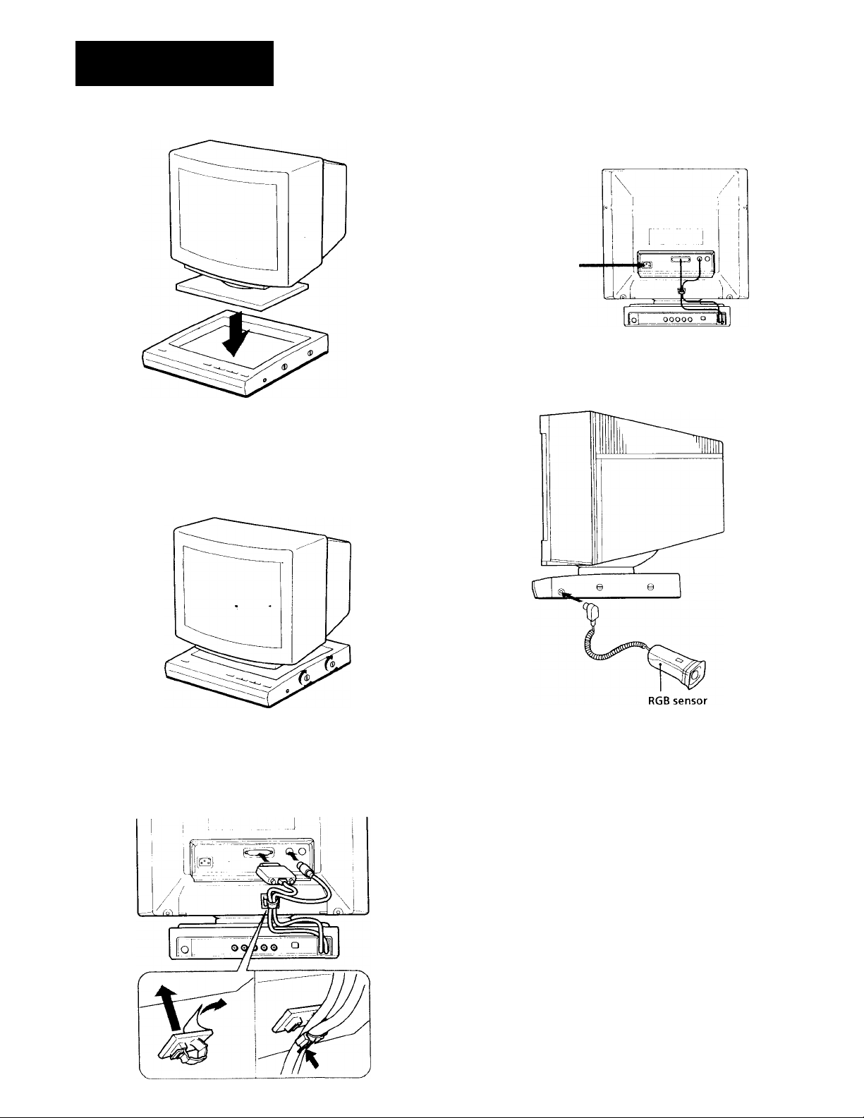
Setting up
1 Set tlie monitor to the control stand.
Do not put your hands between the monitor and
control stand when setting the control stand.
Set the control stand properly so as not to damage it.
Secure the monitor with four screws on right and left sides
of the stand.
4 Connect the AC power cord to the monitor and to a wall
outlet. (Use the shielded AC Power cord included m
your package.)
-asrfin
to a wall outlet
5 Connect the RGB sensor to the PROBE connector.
Be sure to lock all four parts for safety.
3 Put the attached cable clamp on the rear side of the
monitor, connect the signal cord and DC power cord to
the monitor through the clamp, and close up clamp.
Page 5

Using your monitor
Preset and User Modes
The GDM-2000TC has factory preset modes for the 9 most
popular industry standards for true “plug and play"
capability.
NO.
For less common modes, and modes that evolve in the
future, the GDM-2000TC's highly advanced custom ASIC
will perform all of the complex adjustments necessary to
ensure a high quality for any timing between 31.,5 and
85 kHz. However, due to the wide variety of video board on
the market, it may be necessary for the user to fine tune the
vertical/horizontal size centering.
Resolution (dots x lines)
1 640 X 480
2
720 X 400 31.5 kHz
3 800 X 600
4
832 X 624
5
1024 x768
6 1024 x768 60 kHz
7 1152 x870 68.7 kHz
8 1280 X 1024 64 kHz
9 1280 x 1024
For Windows 3.x users, check your video board
manual or the utility program which comes with
your graphic board and select the highest available
refresh rate to maximize monitor performance.
Horizontal Frequency
31.5 kHz
48.1 kHz
49.7 kHz
56.5 kHz
78.9 kHz
Vertical Frequency
60 Hz
70 Hz
72 Hz
75 Hz
70 Hz
75 Hz .
75 Hz
60 Hz
74 Hz
DVGA is a trademark of IBM Corporation.
2) VESA is a trademark of the non-profit organization. Video
Electronics Standard Association.
3) Macintosh is a trademark of Apple Computer Inc.
VGA Graphic "
VGA Text "
VESA
Macintosh 16" Color
VESA
Macintosh 19" Color
Macintosh 21" Color
STD CAD/CAM
High Refresh CAD/CAM
Graphics Mode
Recommended horizontal timing conditions
Horizontal sync width should be: >1.0 p sec.
Horizontal blanking width should be: >3.0 p sec.
Page 6

Function of controls
Front
See the pages mentioned for more information.
[H POWER SAVING indicator
Lights up when tlie monitor is in I’ower Saving Mode,
Flashes when the limit \ alue for an adjustment is
reached (page 12).
[2] d) power switch and indicator
Turn the monitor on and off. I he indicator lights up
when the monitor is turned on.
Reset button
Recalls certain factory settings See "Ad|ustments"
section for details (page 7),
g] MENU button
Press to make the menu appear or to return to the
previous menu.
[5] p (brightness) +/- buttons
SEL (select) ♦/♦ buttons
Adjusts the picture brightness in the normal operation
(page 7).
Acts as cursor (►) up/down buttons in the menu
operation.
Rear
2j REMOTE connector
Fhis connector allows any computer with an RS-2.72C
port to act as the host controller. Serial communication
in this connectiir is based on the RS-232C standard,
d’he monitor has a mini DIN-8 serial port. The figure
below illustrates the pin assignment of the RLMC>TE
port.
1. DTR
2. DSR
3. TXD
11 □□ [Zl d] I
ll3) Video input connectors (5 BNC)
The connector accepts RGB \ ideo signals (D.714 Vp-p,
positive)
|- - VIDEO IN --“1
R
4. GND
5. RXD
5. GND
7. OPEN
8. OPEN
Data Transmit Ready (OUT)
Data Set Ready (IN)
Transmit data (OUT)
Signal Ground
Recieve Data (IN)
Ground
Not Used
Not used
|-SYNC IN j
HD,'COMP VD
[6] a (contrast) +/- buttons
ADJUST +/- buttons
Adjusts the picture contrast in the normal operation
(page 7).
Acts ns +/ - adjusting buttons in tlie menu operation.
[7] ENTER key
Press to select the desired item in a menu.
[8] AC IN connector
Plug in an AC power cord.
[9] SIGNAL connector
Connect the control stand's signal cord.
[H DC OUT connector
Connect the control stand's DC power cord.
[11] SERVICE terminal
I'his terminal is to be used bv serx'ice persoiuu'l only
It you use a.computer or video board of high output
level (about 1.0 Vp-p), you may not be able to obtain the
optimum display. In such case, try decreasing the
picture contrast, or use a computer or video board with
a lower output level.
I14I 75D/2 kU selector
Switches the impedance ot the SYNC' IN connector 14
termination to 7^Ll or to 2 ktl When external sync
signals are input, normally set this selector to the 2 kit
position. It good synchroni/ation cannot be obtained, set
this selector to the 7.312 position.
ll5] PROBE connector
Connect the '-uppliei.l RC.B M'Usor.
Page 7

Adjustments
Adjusting the picture brightness
The adjustment data becomes the common setting tor al
input signals.
Press the O +/- buttons.
♦ SELECT t
-O:
+ " tor more brightness
— lor less brightness
Adjusting the picture contrast
The adjustment data becomes the common setting for all
input signals.
Press the 3 +/- buttons.
- ADJUST +
+
+ for more contrast
~for less contrast
2 Select the item v(hi want to reset to the factory setting
and press ENTER.
If vou si'lect ALL ADjUS'l’MENTS, the menu below
appears.
Select YES and press ENTER to reset.
• If "ALL AOjUSI’ME.NTS" is reset, the brightness ami
contrast are also reset.
. If "COLOR TEMPERATUFRL" is reset, all lour
memory mtides are reset.
• If vou press RESET when either the CCh .OR
TEMPERATURE or COLOR TE.MPERA TURE FINE
ADll.lSTMENT menu (see page K) is on the screen, the
menu belou' appe.irs.
Resetting the picture brightness and contrast
Y(,iu can reset (return to the factory settings of) the picture
brightness and contrast by pressing the - and + (of SELECT
or ADJUST) buttons simultaneously.
Resetting the adjustment
1 Press the RESET button.
RESET
The RESET menu appears on the screen.
RESET
► ALL ADJUSTMENTS
COLOR TEMPERATURE
GEOMETRY.CONVERGENCE
Select YES and press E.NTER to reset.
Onlv the currently selected color temperature mode is
reset.
• If vou press RESEJ when either the CEOV1ETRY or
CONA'ERGENCE menu (see pagi' 8) is on the screen,
the menu beknv' appe.irs.
Select YES and press EN I’ER to reset.
Page 8

Using on-screen menus
The flow chart below shows the different levels of on-screen
menus that you can use to make various adjustments and
settings. The boxed number is for instructions on page 9.
T] Main menu
MENU
BCF AUTO
► COLOR TEMPO .9300K
UNIFORMITY ON
GEOMETRY
CONVERGENCE
USER CONFIG
DEGAUSS
SELEISADja±l
SFTglRlFNDiMENUl
BCF
U COLOR TEMPERATURE menu
COLOR TEMPERATURE
► 1:9300K(STD)
2;6500K(STD)
3:5000K(STD)
4:3000K(STD)
SEI 1ШАП.1Я+1
g] UNIFORMITY ADJUSTMENT
(see page 10, 11)
n GEOMETRY menu
GEOMETRY
► V CENTER
H CENTER
V SIZE
H SIZE
RASTER ROTATION
PINCUSHION
SELliHADJBEl
EXITSHa
ЕХ1ТЕШШ
g] COLOR TEMPERATURE FINE
1 9300K
► RL:
GL
RH
GH
SELSBADJGEI
BL:
BH;
0
0
0
0
0
0
[7j V CENTER
in H CENTER
[9] V SIZE
ill H SIZE
[il] RASTER ROTATION
|12] PINCUSHION
FXITlMgNul
H CONVERGENCE menu
CONVERGENCE
► V CONV
H CONV
SELdBADJEB
m USER CONEIG menu
USER CONFIG
► CLAMP AUTO
MENU POSI CENTER
SELSEIADJEl+l
[i| degauss
ЕХ1Т1ШШ1
ЕХ1ТШШ)
■n:
I
V CONV
i H CONV
HtI clamp
|18] MENU POSITION
8
Page 9

Operating through menus
There are six buttons for menu operations on the front of the
stand. To display the main menu, press MENU at first.
Functions of the buttons
Button Function
MENU Returns to the previous menu.
SELECT ♦/♦
ADJUST+/-
ENTER
Moves the cursor (►) upwards or
downwards.
Increases or decreases the value.
Selects an item.
Front of the stand
MENU
[T] Main menu
Select an item and press ENTER to go to the following
menu.
[2] BCF
Selects the BCF (Beam Current Feedback) mode. This m.ode
detects and controls the CRT beam current to stabilize the
white balance. This will keep color reproduction stabilized
even when you see the unit for a long time.
4- SELECT 4-
— П о
AUTO; automatically detects the current.
MANUAL: detects the current when you press ENTER.
The following are not malfunctions:
• White horizontal lines appear in the upper
end of the screen. This happens when the
lines are detecting the beam current.
• The "BCF" flashes in yellow in the menu
screen. This happens when the beam current
detection and control operation are activated.
Ш COLOR TEMPERATURE menu
Selects the color temperature from 1-4 settings. You
can adjust the range setting from 3000 К to 9300 К in
increments of 100 K.
The factory setting for the color temperature of each
mode is as follows:
Mode Color temperature
1 9300 К User-adjustable
2
6500 К
3 5000 К User-adjustable
4 3000 К User-adjustable
[4] COLOR TEMPERATURE FINE ADJUSTMENT menu
Press MENU while pressing ENTER in the COLOR
TEMPERATURE menu to select this menu. You can
finely adjust the RGB to fine-tune the color temperature
with this menu. For details, see page 10.
[5] UNIFORMITY ADJUSTMENT
Automatically detects and corrects the non-uniformity of
RGB and brightness over the whole screen by using the
attached RGB sensor. The RGB and brightness for the
rest of the screen are corrected by standardization with
the center.
Side effects such as luminance decrease in the center will
not occur.
— ADJUST +
D D
Adjustment status
User-adjustable
ENTER
ON: Correction activated.
OFF: Correction not activated.
If you cannot obtain uniform RGB or luminance
immediately after setting up the unit, or even
while correction is activated, do the Uniformity
adjustment procedure on pages 10 and 11.
Ш GEOMETRY menu
Select an item and press ENTER to go to the following
menu.
Ш V CENTER
Adjusts the vertical centering. Press -t to move the
picture up and press - to move it down.
[8] H CENTER
Adjusts the horizontal centering. Press -r to move the
picture to the right and press - to move it to the left.
d] V SIZE
Adjusts the vertical picture size. Press + to enlarge the
vertical size and press - to diminish it.
m H SIZE
Adjusts the horizontal picture size. Press -r to enlarge the
horizontal size and press - to diminish it.
И RASTER ROTATION
Correct the picture rotation. Press -i- to rotate the picture
clockwise and press - to rotate it counterclockwise.
т PINCUSHION
Correct the picture pincushion. Press + to expand the
picture sides and press - to diminish them.
m CONVERGENCE menu
Select an item and press ENTER to go to the following
menu.
И V CONV
Adjusts the vertical convergence. Press + to move Red
up and Blue down. Press - to move Red down and Blue
up.
51 H CONV
Adjusts the horizontal convergence. Press -i- to move Red
to the right and Blue to the left. Press - to move Red to
the left and Blue to the right.
51 USER CONFIG menu
Select an item and press ENTER to go to the following
menu.
51) CLAMP
With certain video signals, the background level may
appear too bright or greenish. If the brightness controls
cannot correct the problem, reset the clamp pulse to
obtain the correct black background level. Also reset the
clamp pulse when the "BCF" flashes in magenta
repeatedly. You can select AUTO or SYNC ON G.
51 MENU POSITION
You can select the menu display position from among
CENTER, UPPER LEFT, UPPER RIGHT, LOWER
RIGHT, and LOWER LEFT.
51 DEGAUSS
Demagnetizes the screen. Wait for 20 minutes or more
before activating this feature again.The same interval is
needed after turning on the monitor. The wave-like
movement on the screen is not failure. 0
Page 10

Using on-screen menus
COLOR TEMPERATURE FINE Adjustment
This feature allows you to finely adjust the white on the
screen.
Press MENU while pressing ENTER in the COLOR
TEMPERATURE menu. The message below appears:
RL: 0
GL: 0
BL: 0
RH; 0
GH:0
BH: 0
RL, GL and BL adjust the dark white (gray) part of the
screen; RH, GH, and BH adjust the bright white part in the
screen. Set the values of the items from a min. of -128 to a
max. of +127 by pressing the ADJUST +/- buttons. Press +
repeatedly to increase the value, and press - to decrease the
value.
Items with any value other than 0 show that the white point
is out of the standard color temperature curve by the given
value. The (STD) indicator by the color temperature
indicators disappears.
Uniformity adjustment
You can correct the non-uniformity of the color or the
luminance by using this feature.
Before proceeding, connect the RGB sensor to the PROBE
connector on the right side of the stand, and demagnetize
the screen with the DEGAUSS feature explained on page 9.
1 Select UNIFORMITY ADJUSTMENT in the main
menu.
The search miessage appears.
1. Place Sensor in
UPPER LEFT CORNER.
2. Click an(j hold
Put the RGB sensor on the upper left corner of
the screen and click it.
The search message appears.
fxitTmenuI
If the limit value is reached when setting, the operation
stops. Further adjustments to the color configuration may
not be possible even if the values change. The limit value
varies, depending on the color temperature item.
When actually adjusting. Because adjustment of the gray
part and the white part effect each other a little, you may
need to readjust the RL, GL, BL, RH, GH and BH items,
until you get the desired color configuration for both the
gray and white parts.
The chart below presents the RGB configuration.
R(Red)
Yellow
G (Green)
You can easily change a color function by increasing or
decreasing the color function values.
For example:
You can increase the R (Red) function by increasing R.
You can increase the yellow function by increasing R or G,
or by decreasing the B. Decreasing B makes the yellow
darker than the increasing R or G. Similar results occur for
magenta and cyan by adjusting the corresponding color
functions.
1. Place Sensor tn
LOWER RIGHT CORNER
2. Click and hold
Put the sensor on the lower right corner of the
screen and click it.
fxitTmenuI
The message below appears.
SENSOR CALIBRATION
1. Place Sensor over
Black Sguare
2. Click and hold
CD
FXITIMENUI
10
Page 11

Note on steps 2 and 3
Do not place the sensor out of the displayed picture or
remove the sensor from the screen until the next message
appears. Place the sensor vertically to the screen.
Displayed
picture
4 Put the sensor on the mark and click it.
A sensor mark flashes on the screen and the message
below appears.
UNIFORMITY ADJUSTMENT
1 - Place Sensor over
Black Square
2. Click and hold until
NEXT Square appears
3 Repeat Process
□
5 Put the sensor on the mark and click it.
81 ,(9 X 9) marks appear sequentially. After you click the
last one, the finish message appears.
ADJUSTMENT COMPLETE
Press ENTER Key
SETEEIIS) EXlTtMENu)
Do not remove the sensor from the screen, until
the next black square appears. If the next mark
does not appear after a few seconds, there may
be a detection error. Reconfirm the location of
the mark, by placing the sensor on the mark
again, and click it.
' Press MENU to stop the adjustment.
' Place the sensor vertically to the screen to shield
the sensor from the outer light.
FXITTMT)
6 Press ENTER.
The menu appears.
11
Page 12

Power saving function
rhis monitor is capable of 2 states of reduced power
consumption.
State
1
2
3
Power Saving Operation
• If one of the H-sync or V-sync signals is absent, the unit
enters the Suspend state.
• If both the H-Sync and V-Sync signals are absent, the unit
enters the Active-off state.
Normal operation
Suspend
(1st step of power saving)
Active-off
(2nd step of power saving)
Power consumption
1007<
approx. 10% approx. 3 sec.
approx. l°!o approx. 10 sec. off
Specifications
Picture tube
Resolution
Effective picture size
Display picture size
Deflection frequency
0.31 mm phosphor trio pitch
20 inches measured diagonally
(19" visual)
90-degree deflection
Horizontal: Max. 1280 dots
Vertical; Max. 1024 lines
Approx. 388 X 292 mm (w/h)
(15 i:: 11 Vj inches)
Approx. 350 X 280 mm (w/h)
(13 ’/k X 11 '/s inches)
or
360 X 270 mm (w/h)
(14 '/j X 10 Vi inches)
Horizontal: 31.5 to 85 kHz
Vertical; 50 to 150 Hz
By sensing the absence of one or both sync signals coming
from the host computer, it will reduce power consumption
as follows.
Required
resumption time
—
(!) Power
indicator
green on
green on
POWER SAVIG
indicator
off
orange on
orange on
CAUTION: The Power Saving function will automatically
put the monitor into the Active-off state if the
power switch is turned on without any video
signal input. Once the horizontal and vertical
syncs are sensed, the monitor will automatically
return to its Normal operation state.
Color temperature
Input
AC input voltage/current
Dimensions
Mass
Optional accessory
3000 K - 9300 K (1 step 100 K)
R/G/B: 75Q BNC
0.714 Vp-p, Positive
Sync on Green: 0.286 Vp-p, Negative
External sync: 1-5 Vp-p, Negative or
Positive
HD/VD or Composite sync: 2 kii/
75D BNC
100 to 120 V, 50/60 Hz, 3.0 A
220 to 240 V, 50 - 60 Hz, 1.8 A
474 X 513 X 529 mm (w/h/1)
(length including the control stand)
(18 Vi X 20 '/4 X 20 ^/» inches)
Approx. 33 kg (72 lb 12 oz)
TC WARE for Mac: GDM-CWlOO
(Device Profile/Display control
software)
Use of the tilt-swivel
With the tilt-swivel, this unit can be adjusted to be viewed
at your desired angle within 90° horizontally and 20°
vertically.
To turn the unit vertically and horizontally, hold it at its
bottom with both hands as illustrated below.
12
Design and specifications are subject to change without
notice.
Page 13

Troubleshooting
This section m<iy liolp yon isoUite the problem and as a result, eliminate the need to contact technical support and allow
continued productivity.
Symptom Check these items
No picture
If neither (!) (power)
indicator nor I’OWHK
SAVINti indicator is lit
IfPOWKR SAVING
indicator is lit
If Ci) (power) and I’OWER
SAVING indicators are
both flashing
I’icturc is scrambled
Color is not uniform • Trip the power switch once to activate the Auto degauss cycle, or activate the DEGAUSS feature in the
White does iiot look white
Screen image is not centered
Screen image size is not
right
Screen image is tilted
Edges of the image are
curved
Red or blue shades are
found at the edge of images
Picture is fuzzy
Picture bounces or has wavy
oscillations
Uniformity adjustment
cannot be done
"BCE" flashes in magenta
repeatedly.
• Check that the power cord is prtiperlv connected.
• Check that the power switch is in the "ON" position.
• Check that your computer power switch is in the "ON" position.
• Check that the video cable is properly connected and all plugs are firmly seated in thc'ir sockets.
- • Ensure that no pins are bent or pushed in tlie HD13 connector of the cable.
• Check that the video card is seated completely in a proper bus slot. There may be a particular bus slot
specified for your video board to be seated among 8, 16, and VL-Bus slots.
• If the impedance switch on the back of the monitor is set to trv switching to 2 ki l.
• Check that the video sync signal is within that specified for the monitor.
(fH: 31.3 - 85 kHz, fV:' 50 - 150 Hz)
• If using a Mac system, check that a proper HD15-015 adaptor is provided to work correctly with vour Mac.
• Check that the signal cable and 1X2 cable are connected to the monitor.
• If the impedance switch on the back of the monitor is set to 75U, turn off the monitor, move the switch to 2
ki2, and turn on the monitor. If the indicators are still flashing, there is a potential monitor failure. Contact
your dealer.
• If the impedance switch on the back of the monitor is set to 7bil , try switching tt) 2 k£2.
• Check your graphic board manual for proper monitor setting on your GDM-20()()TC,
• Check this manual and confirm that the graphic mode and the frequency at which you are trying to
operate is supported. Even within the proper range some video boards may have a sync pulse that is too
narrow for the monitor to sync correctly.
main menu (page 9). This function is to demagnetize the metal frame of the CRT to obtain neutral field for
uniform color reproduction. If a second degauss cycle is needed, allow a minimum interval of 20 minutes
for the best result.
• Do the Uniformity adjustment procedure properly (page 10, 11).
• Check that the 5 BNC's are connected in the right order, (from power cord side: Ked-Green-Blued ID-VD)
• Perform the color temperature adjustment (page 9).
• If the'video format is not listed in the compatibility table on page 6, there may be a background level
problem (background too bright or greenish). Try the black level clamp toggle switch (page 9).
• Adjust the V CENTER or H CENTER in GEOMETRY menu (page 9),
• Adjust the V SIZE or H SIZE (page 9).
• Some video modes do not fill the screen to the edge of the monitor. There is no single answer to solve the
problem. There is a tendency to have this problem on higher refresh timings and Macintosh video timings.
• Adjust the "RASTER ROTATION" in the GEOMETRY menu (page 9).
• Adjust the "PINCUSION" in the GEOMETRY menu (page 9).
• Adjust the "V CONV" or "H CONV" in the CONVERGENCE menu (page 9).
• Adjust the "Contrast" and "Brightness" controls (page 7). We have come across several brands of SVGA
boards that have an excessive video output level which creates fuzzy picture at max contrast.
• Trip the power switch once to activate the Auto-degauss cycle. This function demagnetizes the metal
frame of the CRT to obtain a neutral field for uniform color reproduction. If a second degauss cycle is
needed, allow a minimum interval of 20 minutes for the best result.
• If a white line shows color shades, adjust the "V CONV" or "11 CONV" setting in the CONVERGENCE
menu to see if the shades are eliminated.
• Move electrical (magnetic) devices that may be creating etpc'trical interference away from the monitor.
• If you have another monitor dose to this monitor, increase the distance between them to reduce the
interference.
• Your office may have electric power wiring behind the wall. Move the monitor away from the wall.
• Check that the RGB sensor is correctly connected.
• C heck that you place on the RGB sensor on the correct screen position.
• Try setting the clamp pulse again (see page 9).
If the problem persists, call your authorized Sony dealer from a location near your monitor.
Note the model name and the serial number of your monitor. Also note the make and name of your computer and video
board.
13
 Loading...