

Page 1
FWD-42PV1/42PV1P/42PV1A
2-581-145-13 (1)
Flat Panel Display
取扱説明書
Operating Instructions
Mode d’emploi
Bedienungsanleitung
Manual de instrucciones
Istruzioni per l’uso
使用说明书
お買い上げいただきありがとうございます。
この取扱説明書には、事故を防ぐための重要な注意事項と製品の取り扱
いかたを示してあります。この取扱説明書をよくお読みのうえ、製品を
安全にお使いください。お読みになったあとは、いつでも見られるとこ
ろに必ず保管してください。
電気製品は安全のための注意事項を守らないと、
火災や人身事故になることがあります。
JP
GB
FR
DE
ES
IT
CS
FWD-42PV1/42PV1P/42PV1A
2005 Sony Corporation
Page 2
安全のために
ソニー製品は安全に充分配慮して設計されています。しかし、電気製品は、
まちがった使いかたをすると、火災や感電などにより死亡や大けがなど人身
事故につながることがあり、危険です。
事故を防ぐために次のことを必ずお守りください。
安全のための注意事項を守る
5(JP)〜 7(JP)ページの注意事項をよくお読みください。
8(JP)ページの「本機の性能を保持するために」もあわせてお読みください。
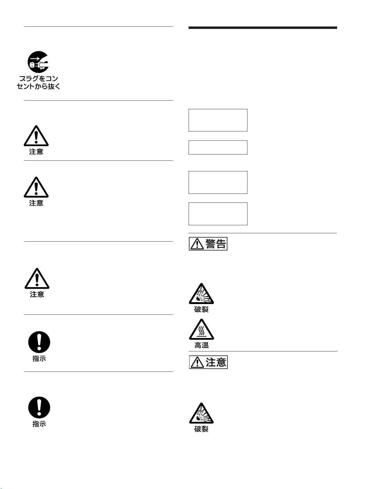
警告表示の意味
取扱説明書および製品では、次の
ような表示をしています。表示の
内容をよく理解してから本文をお
読みください。
定期点検をする
5年に1度は、内部の点検を、お買い上げ店またはソニーのサービス窓口に
ご依頼ください(有料)。
故障したら使わない
すぐに、お買い上げ店またはソニーのサービス窓口にご連絡ください。
万一、異常が起きたら
・ 煙が出たら
・ 異常な音、におい
がしたら
・ 内部に水、異物が
入ったら
・ 製品を落としたり
キャビネットを破
損したときは
,
1 ディスプレイの電源を切る。
2 ディスプレイの電源コードや接続
コードを抜く。
3 お買い上げ店またはソニーの
サービス窓口に連絡する。
この表示の注意事項を守らないと、
火災や感電などにより死亡や大け
がなど人身事故につながることが
あります。
この表示の注意事項を守らないと、
感電やその他の事故によりけがを
したり周辺の物品に損害を与えた
りすることがあります。
注意を促す記号
この装置は、情報処理装置等電波障害自主規制協議会(VCCI)の基準に基づくクラス
B情報技術装置です。この装 置は、家庭環境で使用することを目的としていますが、この
装置がラジオやテレビジョン受信機に近接して使用されると、受信障害を引き起こすこと
があります。
取扱説明書に従って正しい取り扱いをしてください。
(JP)
2
行為を禁止する記号
行為を指示する記号
Page 3

目次
...............................................................................
...............................................................................
電池についての安全上のご注意 ............................................
万一、異常が起きたら ....................................................................... 7(JP)
本機の性能を保持するために ...............................................
各部の名称と働き .................................................................
前面/後面/左側面/右側面/底面 ............................................. 9(JP)
インジケーター部 .............................................................................. 10(JP)
コントロールボタン 部( 上面)........................................................... 10(JP)
入出力端子パネル(底面).............................................................. 11(JP)
入出力端子パネル(左側面).......................................................... 12(JP)
リモコン RM-980 ............................................................................... 14(JP)
使用上のご注意 ..................................................................
接続 ....................................................................................
スピ ーカーの接続 ............................................................................ 17(JP)
電源コードの接続 ............................................................................ 17(JP)
ケーブルを処理する ........................................................................ 18(JP)
メニューで行う調整と設定 .................................................
メニュー の操作 ................................................................................ 19(JP)
メニュー の説明 ................................................................................ 19(JP)
5 (JP)
6 (JP)
7 (JP)
8 (JP)
9 (JP)
16 (JP)
17 (JP)
19 (JP)
JP
日
本
語
画像を見る .........................................................................
入力信号を切り換える ..................................................................... 25(JP)
入力信号と画質モードの情報とディスプレイの 設定状態の
表示について ............................................................................ 25(JP)
画質を選ぶ .........................................................................
画質を調整する ..................................................................
コントラスト、明るさ、色の濃さ、色あいなどを調整する .................. 27(JP)
調整した画質を出荷時の設定値に戻す ......................................... 29(JP)
映像を拡大する ..................................................................
オートワイドを設定する ..................................................................... 30(JP)
ワイド切換を設定する ...................................................................... 31(JP)
画像のサイズや位置を調整する ..........................................
画像のサイズ、位置、ドット位 相などを 調整する ............................. 32(JP)
調整した画像のサイズや位置を出荷時の状態に戻す ................... 33(JP)
つの画面を表示させる .....................................................
2
操作する画面を選んだり、画面の位置を入れ替える ..................... 34(JP)
画面の大きさを 変える ...................................................................... 35(JP)
副画面の位置を調整する(PinPのみ).......................................... 35(JP)
マルチディスプレイの設定をする ......................................
25 (JP)
27 (JP)
27 (JP)
30 (JP)
32 (JP)
34 (JP)
36 (JP)
3
(JP)
Page 4

音質を調整する ..................................................................
高音、低音、バランスなどを調整する............................................. 37(JP)
調整した音質を出荷時の設定に戻す ............................................. 37(JP)
37 (JP)
メニュー表示の言語を選ぶ .................................................
カラーマトリクスを調整する .............................................
電源のオン/オフを自動的に制御する(タイマー機能)........
時刻と曜日を設定する .................................................................... 39(JP)
時計を表示する ............................................................................... 39(JP)
電源タイマー機能 ............................................................................ 39(JP)
スクリーンセーバー機能 ....................................................
画像の色あいを反転させる ............................................................. 40(JP)
画像の表示位置を自動的に変える .................................................41(JP)
画面全体に白画像を出す ............................................................... 42(JP)
背景の明るさを 変える ...................................................................... 42(JP)
画面を徐々に 暗くする ...................................................................... 42(JP)
アドレスおよび通信速度を設定する ...............................
IP
IPアドレスを 自 動取得する(DHCP).............................................. 43(JP)
IPアドレスを マニ ュア ルで設定する(Manual).............................. 43(JP)
通信速度を設定する(SpeedSetup) ............................................... 44(JP)
自己診断機能 ......................................................................
特定のディスプレイをリモコンで操作する ........................
仕様 ....................................................................................
38 (JP)
38 (JP)
39 (JP)
40 (JP)
43 (JP)
44 (JP)
44 (JP)
47 (JP)
保証書とアフターサービス .................................................
49 (JP)
4
(JP)
Page 5
設置・取り付けは確実に
火災
感電
下記の注意を守らないと、
火災や感電により死亡や大けがに
つながることがあります。
規定の電源電圧で使う
この取扱説明書に記されている電源電圧でお
使いください。
規定外の電源電圧での使用は、火災や感電の
原因となります。
油煙、湯気、湿気、ほこりの多い場所では設
置・使用しない
上記のような場所に設置すると、火災や感電
の原因となります。
この取扱説明書に記されている仕様条件以外の
環境での使用は、火災や感電の原因となります。
分解や改造をしない
分解や改造をすると、火災や感電、けがの原
因となることがあります。
内部の点検や修理は、お買い上げ店またはソ
ニーのサービス窓口にご依頼ください。
電源コードを傷つけない
電源コードを傷つけると、火災や感電の原因
となります。次の項目を必ずお守りください。
設置時に、製品と壁やラック、棚などの間
•
に、はさみ込まない。
電源コードを加工したり、傷つけたりし
•
ない。
重いものをのせたり、引っ張ったりしない。
•
熱器具に近づけたり、加熱したりしない。
•
電源コードを抜くときは、必ずプラグを
•
持って抜く。
万一、電源コードが傷んだら、お買い上げ店
またはソニーのサービス窓口に交換をご依頼
ください。
不確実な設置を行うと、ディスプレイが転倒
してけがや火災・感電の原因となります。設
置の際は、以下の注意事項を必ずお守りくだ
さい。
壁面・天井・台上への設置、または転倒防
止のためディスプレイを固定するなど、特
殊な設置を行う場合には、必ずお買い上げ
店に工事を依頼してください。
衝撃を与えない
本機の前面にガラスを使用しているため、衝
撃を与えるとガラスが割れ、けがの原因とな
ることがあります。
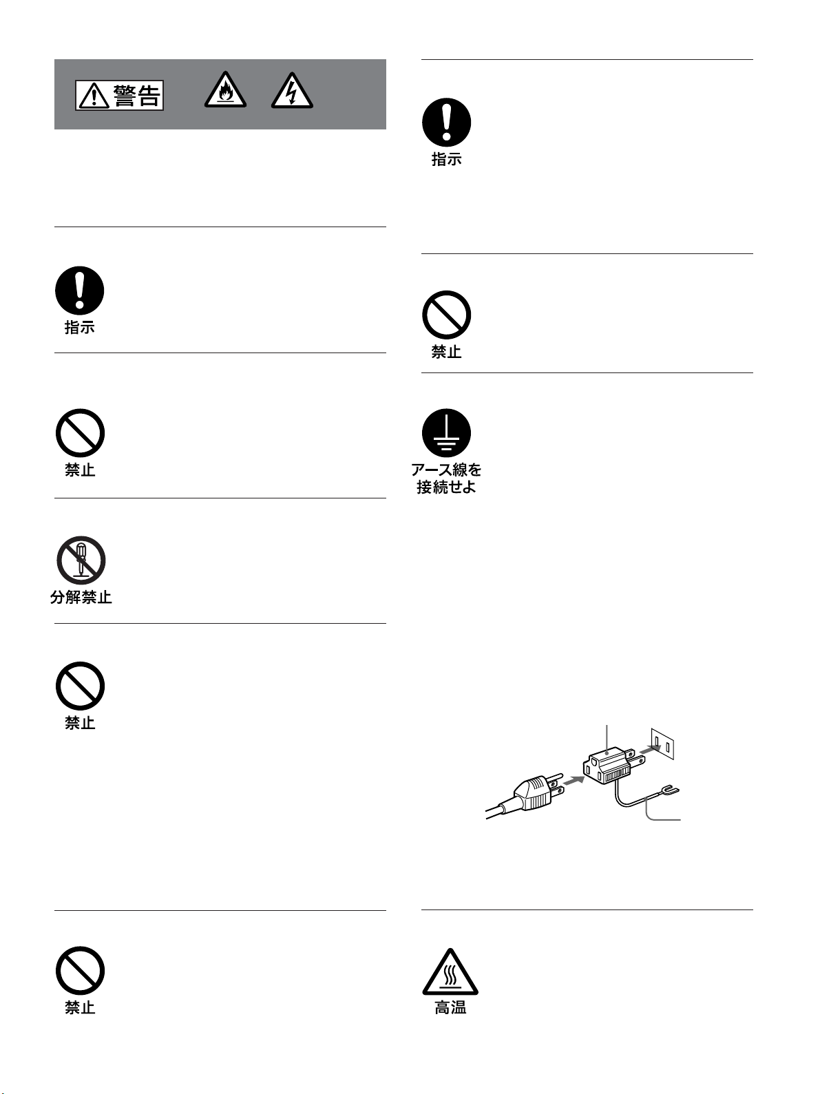
安全アースを接続する
安全アースを接続しないと、感電の原因とな
ることがあります。次の方法でアースを接続
してください。
電源コンセントが 3 極の場合
•
付属の電源コードを使用することで、安全
アースが接続されます。
電源コンセントが 2 極の場合
•
付属の 3 極→2 極の変換プラグアダプター
を使用し、変換プラグアダプターから出て
いる緑色のアースを、建物に備えられてい
るアース端子に接続する。
アース接続は、必ず電源プラグを電源につ
•
なぐ前に行ってください。
また、アース接続をはずす場合は、必ず電
源プラグを電源から切り離してから行って
ください。
変換プラグアダプター
不明な点はお買い上げ店またはソニーのサー
ビス窓口にご相談ください。
アース線
内部に水や異物をいれない
水や異物が入ると火災や感電の原因となるこ
とがあります。
万一、水や異物が入ったときは、すぐに電源
を切り、電源コードや接続コードを抜いて、
お買い上げ店またはソニーのサービス窓口に
ご相談ください。
高温部分に触れない
機器を使用中または使用直後には上面や側面
が高温になっているため、やけどをすること
があります。
使用中および電源を切るまたはスタンバイし
た状態から 10 分間は触れないでください。
5
(JP)
Page 6
下記の注意を守らないと、
けがをしたり周辺の物品に損害を与える
ことがあります。
指定された電源コード、接続ケーブルを使う
付属の、あるいは取扱説明書に記されている
電源コード、接続ケーブルを使わないと、感
電や故障の原因となることがあります。
他の電源コードや接続ケーブルを使用する場
合は、お買い上げ店またはソニーのサービス
窓口にご相談ください。
重いディスプレイは、2人以上で開梱・運搬する
ディスプレイは見た目より重量があります。
開梱・運搬は、けがや事故を防ぐため、必ず
2人以上で行ってください。1人で行うと腰を
痛めることがあります。
本体を持って運搬する
ディスプレイを運ぶときは、スピーカー部分
を持たず、必ず本体を持ってください。ス
ピーカーがディスプレイからはずれて落下
し、けがの原因となることがあります。
ぬれた手で電源プラグをさわらない
ぬれた手で電源プラグを抜き差しすると、感
電の原因となることがあります。
水のある場所に設置しない
水が入ったり、ぬれたりすると、火災や感電
の原因となることがあります。雨天や降雪
中、海岸や水辺での使用は特にご注意くだ
さい。
通風孔をふさがない
通風孔をふさぐと内部に熱がこもり、火災や
故障の原因となることがあります。風通しを
よくするために次の項目をお守りください。
使用上のご注意の項(16 (JP)ページ)に
•
従って設置してください。
密閉された狭い場所に押し込めない。
•
毛足の長い敷物(じゅうたんや布団など)
•
の上に設置しない。
布などで包まない。
•
あお向けや横倒し、逆さまにしない。
•
設置時には必ずスタンドを使用する
ディスプレイの転倒によるけがや事故を防ぐ
ため、台・床などに本機を据え置きする際は、
別売りの専用スタンド(SU-42FW/32FW)を
ご使用ください。
設置時には転倒防止処置を行う
本機を据え置きする際には、万一の場合に備
え、転倒防止処置を行ってください。
不安定な場所に設置しない
ぐらついた台の上や傾いたところなどに設置
すると、ディスプレイが落ちたり、倒れたり
して、けがの原因となることがあります。
また、設置・取り付け場所の強度を充分にお
確かめください。
接続の際は電源を切る
電源コードや接続ケーブルを接続するとき
は、電源を切ってください。感電や故障の原
因となることがあります。
(JP)
6
直射日光の当たる場所や熱器具の近くに設
置・保管しない
内部の温度が上がり、火災や故障の原因とな
ることがあります。
電源コードのプラグおよびコネクターは突き
当たるまで差し込む
まっすぐに突き当たるまで差し込まないと、
火災や感電の原因となります。
Page 7
お手入れの際は、電源を切って電源プラグを
抜く
電源を接続したままお手入れをすると、感電
の原因となることがあります。
電池についての安全上の
ご注意
ここでは、本機での使用が可能なソニー製アルカリ乾電池に
ついての注意事項を記載しています。
万一、異常が起きたら
移動させるときは電源コード、接続ケーブル
を抜く
接続したまま移動させると、電源コードや接
続ケーブルが傷つき、火災や感電の原因とな
ることがあります。
定期的に内部の掃除を依頼する
長い間、掃除をしないと内部にホコリがたま
り、火災や感電の原因となることがありま
す。1 年に 1 度は、内部の掃除をお買い上げ
店またはソニーのサービス窓口にご依頼くだ
さい(有料)。
特に、湿気の多くなる梅雨の前に掃除をする
と、より効果的です。
人が通行するような場所に置かない
コード類は正しく配置する
電源コードや信号ケーブルは、足に引っかけ
ると製品の落下や転倒などによりけがの原因
となることがあります。人が踏んだり、引っ
かけたりするような恐れのある場所を避け、
十分注意して接続・配置してください。
すぐにきれ いな水で洗い、ただ
電池の液が目に
入ったら
煙が出たら
電池の液が皮膚や
衣服に付いたら
バッテリー 収 納部内
で液が漏れたら
,
ちに医師の治療を受ける。
1 電池を抜く。
,
2 お買い上げ店またはソニー
のサービス窓口に連絡する。
すぐにきれ いな水 で洗い流す。
,
よくふき取 っ てから、新し い 電
,
池を入 れる。
下記の注意事項を守らないと、
破裂・発熱・液漏れにより、
死亡や大けがなどの人身事故になることがあ
ります。
乾電池は充電しない。
•
火の中に入れない。ショートさせたり、分
•
解、加熱しない。
指定された種類の電池を使用する。
•
コード類は正しく配置する
電源コードや接続ケーブルは、足に引っかけ
ると本機の落下や転倒などによりけがの原因
となることがあります。
十分注意して接続・配置してください。
変換プラグアダプターのアースキャップは幼
児の手の届かないところに保管する
万一、誤って飲み込んだときは、窒息する恐
れがありますので、ただちに医師にご相談く
ださい。
使用済みの電池は、地域のルールに
従って処分してください。
下記の注意事項を守らないと、
破裂・液漏れにより、けがをし
たり周辺の物品に損害を与えたりする
ことがあります。
投げつけない。
•
使用推奨期限内(乾電池に記載)の乾電池
•
を使用する。
3 と # の向きを正しく入れる。
•
電池を入れたまま長期間放置しない。
•
新しい電池と使用した電池は混ぜて使わな
•
い。
種類の違う電池を混ぜて使わない。
•
水や海水につけたり濡らしたりしない。
•
(JP)
7
Page 8

本機の性能を保持するために
本機の性能を保持するた
めに
(プラズマディスプレイパネル)について
PDP
画面上に赤や青、緑の点(輝点)が消えなかったり、黒い点(滅
•
点)がある場合があります が、故障ではありません。パネルは非
常に精密な技術で作られており、ごくわ ず かの画素欠けや常に
点灯する画素がある場合があります。ご了承ください。また、画
面の上下端および左右端に常に光らない部分がありますが、故
障ではありません。また、すじ状 の色 むらや明るさのムラが見え
る場合もありますが、故障ではありません。
高山地など気圧の低いところで使用するとプラズマディスプレイ
•
パネルの構造上、ブーン音(バズ音)が発生することがありま
す。
一定時間同じ画像を表示し続けると、部分的に残像や焼きつき
•
が発生することがあります。
一定時間画像を表示し続けるときは、画面の焼きつきを避けるた
め、本機のスクリーンセーバー機能を使用し、全画面表示してく
ださい。焼きつきが発生したときは、本機のスクリーンセー バ ー機
能を使用するか、ビデオソフトなどの動きのある映像を映してくだ
さい。焼きつきが軽度のときは、次第に目立たなくなることが あり
ますが、一度発生した焼きつきは、完全には 消えません。
本機はプラズマディスプレイの保護のため電源ON/STANDBY
•
に時間をかけており、その間リモコンおよび本体の操作ボタンに
よる操 作を 受 け 付けませ ん。約 5秒待ってから操作をしてくださ
い。
クリーニングについて
お手入れをする前に、必ず電源プラグをコンセントから抜 いてく
•
ださい。
乾いた柔らかい布で軽く拭いてください。汚 れがひどいときは 、
•
薄い中性洗剤溶液を少し含ませた布で拭きとり、乾いた布でか
ら拭きしてください。
アルコールやベンジン、シンナー、殺虫剤などは使わないでくだ
•
さい。表面の仕上げを傷めたり、表示が消えてしまうことが ありま
す。
ディスプレイのガラス表面の取扱いについての
ご注意
ディスプレイの表面は傷つきやすいので、硬いものでこすっ
たり、たたいたり、ものをぶつけたりしないでください。
設置についてのご注意
他の機器と組み合わせて設置する場合、各機器の設置位置
•
などにより、リモ コン の誤動作や映像の乱れ、雑音などが起こ
ることが ありま す。この場 合は、お買い上げ店、またはソニーの
サービス窓口にご連絡ください。
(JP)
8
Page 9
各部の名称と働き
2 3
5
7
76
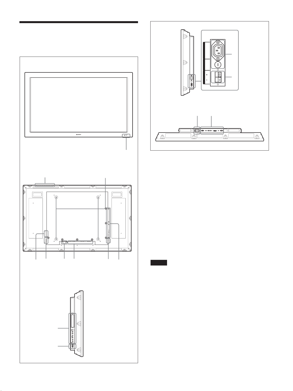
各部の名称と働き
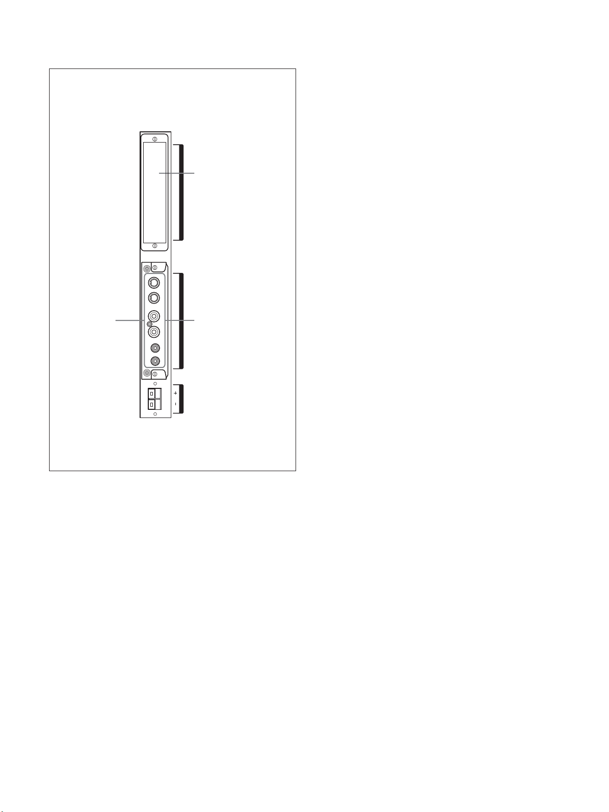
前面/後面/左側面/右側面/底面
前面
1
後面
右側面
100-240V~ 50-60Hz
Maximum 0.25A
4
T500mA H
250V
SPEAKER RAC OUT FUSE
5
底面
1 インジケーター部
◆インジケーター部について詳しくは、「インジケーター 部 」(10(JP)ペー
ジ)をご覧ください。
4 756
左側面
7
5
2 コントロールボタン部
◆コントロールボタン部について詳しくは、「コントロールボタン部(上面)」
(10(JP)ページ)をご覧ください。
3 スタンド取り付け用フック
スタンド(別売り)を取り付 けるときに 使 用します。
4
AC OUT
(電源出力)端子(3極端子)
システムを組むときに、消費電力の小さな機器を接続して電源を
供給することができます(定格電流最大0.25Aあるいは最大消費
電力30Wまで)。詳しくは、お買い上げ店またはソニーのサービス
窓口にご相談ください 。
ご注意
定格電流・最大消費電力を超える機器をACOUT端子に接続し
ないでください。
5
SPEAKER
(スピーカー)端子
スピ ー カー(別売り)を接続すると、画面に表示されている信号の
音声を出力します。
6 -
(電源入力)端子
AC IN
付属の電源コードを 使用して、AC電源に接続します。AC 電源に
接続すると、POWER/STANDBYインジ ケーターが 赤色に 点灯し、
本機はスタンバイ状態になります。
◆電源コードの接続について詳しくは、「電源コードの接続」(17(JP)
ページ)をご覧ください 。
◆ 入出力端子パネルについて詳しくは、「入出力端子パネル(底面)」
(11(JP)ページ)および「入出力端子パネル(左側面)」(12(JP)ペー
ジ)をご覧ください。
9
(JP)
7 入出力端子パネル
Page 10
各部の名称と働き
1
2
3
4
5
6
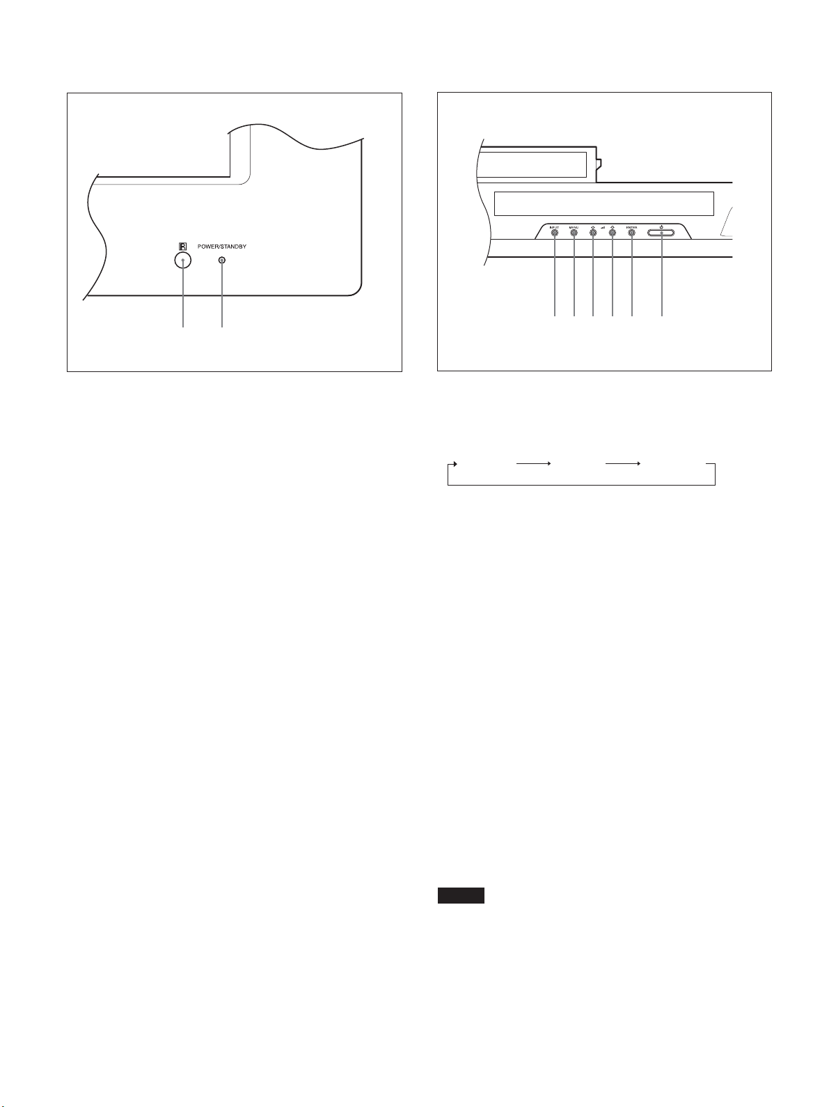
インジケーター部
1 2
1 リモコン受光部
ここでリモ コン の 信 号 を 受 けま す。
2
POWER/STANDBY
ター
モニターの電源を入れると緑色に点灯します。スタンバ イ状態のと
き、インジケーターが 赤色 に 点灯します 。また P C 入力 のとき、パ
ワーセービング状態になると、インジケーターが オレンジ色に 点灯
します。
◆ POWER/STANDBYインジケーターが点滅したときは、「自己診
断機能」(44(JP)ページ)をご覧ください。
(電源/スタンバイ)インジケー
コントロールボタン部(上面)
1
INPUTまたはOPTION端子に接続した機器からの入力信号を選
びます。
INPUT1 INPUT2 OPTION1
の順に入力信号を切り換えます。
OPTION1スロットに オプションアダプターがないときは 、スキップ
します。
2
画面にメニューを出すときに使用します。もう一度押すとメニュー
が消えます。
(インプット)ボタン
INPUT
(メニュー)ボタン
MENU
34
メニュー でカーソル(黄色)を移動するときや数値などを設定する
とき、スピ ーカー から出る音 量を 調節するときに使用します。
5
メニュー で、設 定した内容を確定するときに使用します。
6 1
スイッチを押 すと電源が入り、もう一度押すとスタンバイ状態に戻
ります 。
ご注意
パネル保護のため電源ON/STANDBYに時間がかかります。約
5秒待ってから次の操作をしてください。
M(カーソル移動/音量調節)ボタン
m/
ENTER
(エンター)ボタン
POWER
(パワー)スイッチ
10
(JP)
Page 11
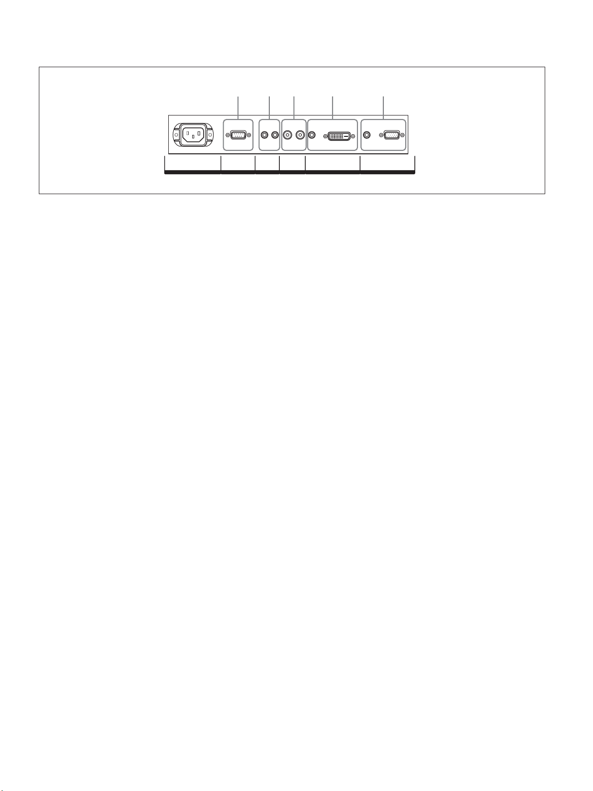
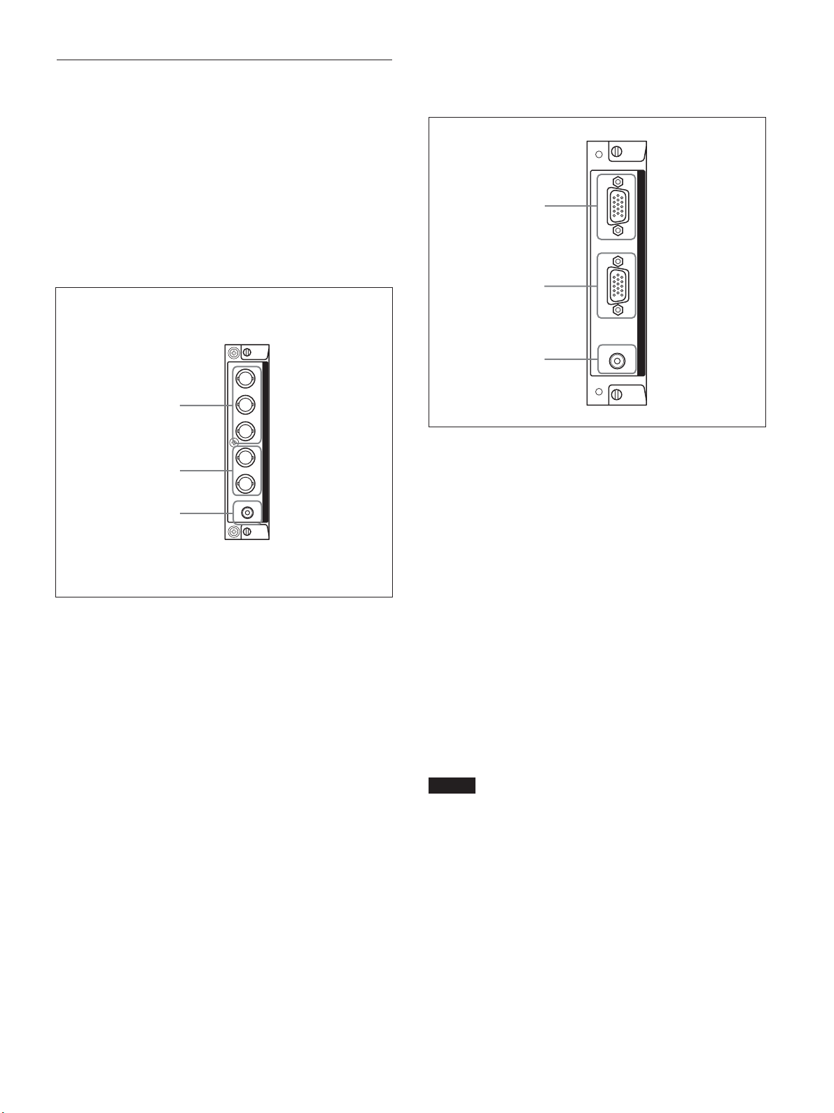
入出力端子パネル(底面)
1 52 3 4
各部の名称と働き
OUTIN L
CONTROL S
1
REMOTE(RS-232C
)用端子(
AC IN REMOTE
D-sub 9
ピン)
RS-232Cプロトコルを使って、リモ ートコントロールを行う場合に接
続します。詳しくはお買い上げ店またはソニーのサービス窓口にご
相談ください。
2
CONTROL S IN/OUT
(コントロールS信号入力/出
力)端子(ミニジャック)
ビデオ機器や他のディスプレイの CONTROLS 端子に接続する
と、1 台のリモコンで複数の機器を操作できます。本機の
CONTROLSOUT端子と他の機器のCONTROLSIN端子、本
機のCONTROLSIN端子と他の機器のCONTROLSOUT端子
を接続します。
3
AUDIO OUT L/R
(音声出力)端子(ピンジャック)
AUDIO端子に入力した音声信号のうち画面に表示されている信
号の音声を出力します。
2画 面(P&P、PinP)のときは、アクティブ画面の音声信号を出力
します。
AUDIO AUDIO
R
AUDIO OUT
DVI-HDCP
INPUT 1 INPUT 2
RGB/COMPONENT
4
INPUT 1
(デジタル
DVI
(デジタル
信号入力)端子:映像機器などのデジタル
RGB
信号入力)端子
RGB
RGB信号出力端子と接続します。HDCP のコンテンツ保護
に対応しています。
AUDIO
(音声入力)端子(ステレオミニジャック):音声信号
を入力します。映像機器などの音声出力端子と接続します。
5
INPUT 2
RGB/COMPONENT
(アナログ
入力)端子(
RGB/COMPONENT
(アナログ
D-sub 15
ピン):映像機器などのアナログ
コンポ ー ネント信 号
RGB/
信号入力)端子
RGB信号出力端子、またはコンポーネント(YUV)信号出力
端子と接続します。
AUDIO
(音声入力)端子(ステレオミニジャック):音声信号
を入力します。映像機器などの音声出力端子と接続します。
11
(JP)
Page 12
各部の名称と働き
入出力端子パネル(左側面)
COMMUNICATION
6
スロット
COMMUNICATIONOPTION 1 (VIDEO/COM)SPEAKER L
7 8
OPTION1(VIDEO/
COM)スロット
6
COMMUNICATION
通信機能に対応したスロットで す。
工場出荷状態では、ふた板が装着されています。
オプションアダプターBKM-FW32(別売り)を装着すると、ネット
ワーク経 由でディスプレイを制御することができます。
7
VIDEO
ル)
S VIDEO IN
S VIDEO OUT
VIDEO IN
VIDEO OUT
AUDIO IN L/R
8
OPTION1(VIDEO/COM
映像信号と通信機能に対応したスロットで す。
(ビデオ)端子(
(映像入力)端子(ミニ
器のY/C 出力端子と接続します。
(映像出力)端子(ミニ
機器のY/C 入力端子と接続します。
(映像入力)端子(
信号出力端子と接続します。
(映像出力)端子(
デオ信号入力端子と接続します。
(音声入力)端子(ピンジャック):音声信
号を入力します。映像機器の音声出力端子と接続します。
スロット
BKM-FW10
BNC
)スロット
プリインストー
ピン):映像機
DIN4
ピン):映像
DIN4
型):映像機器のビデオ
型):映像機器のビ
BNC
12
(JP)
Page 13
オプションアダプター(別売り)
入力端子パネル7の端子部はスロットイン方式になっていて、別
売りの以下のオプションアダプターに付 け 換えることが できます 。
BKM-FW10/BKM-FW11/BKM-FW12
(BKM-FW10は7と同じもの で す。)
◆各アダプターの取り付けかたについては、お買い上げ店またはソニー
のサービス窓口にご相談ください。
コンポーネントアクティブスルーアダプター
RGB/
(別売り)
FW12
1
各部の名称と働き
BKM-
IN
コンポーネント
入力アダプター
/RGB
BKM-FW11
り)
1
R/CR/R PB/CB/B Y/G
2
VD HD P
COMPONENT/RGB INPUT ADAPTOR
3
1
Y/G PB/CB/B PR/CR/R
AUDIO
映像入力端子(
BNC
像機器やコンピューターのコンポーネント信号出力端子または
アナログ RGB信号出力端子と接続します。
2
HD VD
同期信号入力端子(
型):コンピ ューター の
BNC
同期信号出力端子と接続します。
3
AUDIO
(音声入力)端子(ステレオミニジャック):音声信
号を入 力します。映像機器やコンピューターの音声出力端子
と接続します。
(別売
型):映
2
3
1
RGB/COMPONENT IN(RGB/
力)端子(
D-sub 15
ピン):
OUT
RGB/COMPONENT THROUGH
IN
AUDIO
コンポーネント信号入
コンピ ューターや 映像機器のアナログRGB信号出力端子またはコ
ンポーネント信号出力端子と接続します。
コンポ ー ネント信 号をこの端子へ入力する場合には、48(JP)ペー
ジのピン配 列を参 考にしてください。
2
RGB/COMPONENT OUT(RGB/
号出力)端子(
D-sub 15
ピン):
コンポーネント信
コンピ ューターや 映像機器のアナログRGB信号入力端子またはコ
ンポーネント信号入力端子と接続します。
3
AUDIO IN
(音声入力)端子(ステレオミニジャック):
音声信号を入力します。コンピ ューター や映像機器の音声出力端
子と接続します。
ご注意
本体がスタンバイ状態のときやAC 電源が接続されていないとき
は、RGB/COMPONENTOUT からは出力されません。
その他のオプションアダ プター(別売り)については、お買い上げ
店またはソニーのサービス窓口にご相談ください。
(JP)
13
Page 14
各部の名称と働き
RM-980
OR
Y
ON
SET
ON
0
8
9
5
6
1
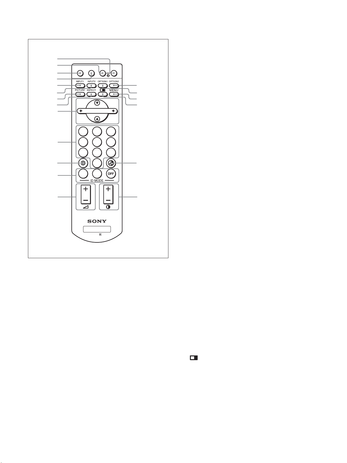
リモコン
2
3
4
5
6
7
8
9
0
qa
qs
qd
RM-980
MUTINGDISPLAYSTB
MONIT
qf
qg
qh
qj
213
qk
ql
7
PICTURE
画質モードを切り換えます。ボタンを 押 す ご とに 、ダイナミック、ス
タンダ ード、ユーザー 1〜 3の順に切り換 わります。
8
ASPECT
画面の横縦比(ズームモード)を選択します。
9 M
/m/</,/ENTER
M/m/</,ボタンでメニューのカーソル(黄色)を移動させた
り、数 値 などを 設 定し ま す 。ENTERボタンを押すと、選んだメ
ニューや設定した内容を確定します 。
0 数字ボタン
インデックス番号を入力するときに使用します。
qa
BRIGHTNESS
画質モードが「ユーザー 1 〜 3 」の とき、画 像 の 明るさを調整しま
す。このボタンを押した後に M/mまたは </,ボタン9で調整
します。
qs
ID MODE (ON/SET/OFF
ONボタンを押すとインデックスナンバーが 画面 に 表示されます。
数字ボタン0で、操作したいディスプレイのインデックスナンバー
を入力しSETボタンを押します。OFFボタンを押すと、IDモードを
抜けて通常の画面に戻ります。
◆インデックスナンバーについて詳しくは、「特定のディスプレイをリモ コン
で操作する」(44(JP)ページ)をご覧ください。
ボタン
ボタン
(エンター)ボタン
(ブライトネス)ボタン
)ボタン
1
POWER
押すと電源が入ります。
2
STANDBY
押すとスタンバイ状態になります。
3
MUTING
音を消します。もう一度押すと、音が出ます。
4
DISPLAY
入力されている信号の種類および画質モードを 画 面 に表 示しま
す。もう一度押すと表示は消えます。表示された状態で約 5 秒た
つと自 動 的に表示は消えます。
5
INPUT1
INPUT1端子に接続した機器からの入力信号を選びます。
6
INPUT2
INPUT2端子に接続した機器からの入力信号を選びます。
ボタンを押 すたびに、RGB、COMPONENT が切り換わります。
(電源)ONスイッチ
ボタン
ボタン
ボタン
ボタン
ボタン
qd
VOLUME+/
音量を調整します。
qf
OPTION2
本機では無効なボタンとなります。
qg
OPTION1
オプションアダ プターを 装着した 際、そこに 接 続し た機器からの入
力信号を選びます。
ボタンを押 すたびに、OPTION1 の入力が切り換わります。
qh
MENU
画面にメニューを出すときに使用します。もう一度押すとメニュー
が消えます。
ボタン
qj
2画面モードを切り換えます。ボタンを押すごとに、2画面オフ、
P&P、PinP の順に切り換わります。
−ボタン
ボタン
ボタン
(メニュー)ボタン
(JP)
14
Page 15
各部の名称と働き
qk
CHROMA
画質モードが「 ユーザー1〜3」のとき、画像の色の濃さを調整し
ます。このボタンを押した後に、M/mまたは </,ボタン9で調
整します。
ql
CONTRAST
画質モードが「ユーザー 1 〜 3」のとき、画像のコントラストを調整
します。
ボタン
(コントラスト)+/−ボタン
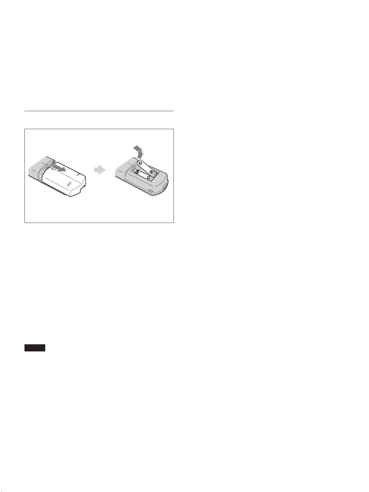
電池の入れかた
単4形乾
電池2個
必ず#極側から電池を
入れてください。
電池の寿命は、通常の使用で約6か月です。リモコン 操 作が効か
なくなり始めたら寿 命ですので、新しい 電池とお 取り換えください 。
リモコンで操作できないときは
POWER/STANDBYインジ ケーターが 点灯し て いるかどうか確認
してください。また、リモートコントロール設定メニューのコントロー
ルモードが「本体のみ」になっていないかどうか確認してくださ
い。ディスプレイ本体の電源が入っているときか、スタンバイ状態
のときで、コントロールモードが「本体+リモコン」または「リモコン
のみ」のときリモコン で操作できます。
◆リモートモードにつ い て詳しくは、「コントロ ー ル モ ード」(22(JP)ページ)
をご覧ください。
ご注意
落としたり、踏みつけたり、中に液体をこぼしたりしないよう、て
•
いねいに扱ってください 。
直射日光が当たるところ、暖房器具のそばの温度が高いところ、
•
湿気が多いところには置かないでください。
ディスプレイ本体 のリモコン受光 部に、直射日光や照明器具の強
•
い光が当たらないようにしてください。リモコンで 操 作ができなく
なる場 合 があります 。
ディスプレイを操作するために必要なボタンがついていますの
•
で、紛失しないようにし てください。
15
(JP)
Page 16
使用上のご注意
使用上のご注意
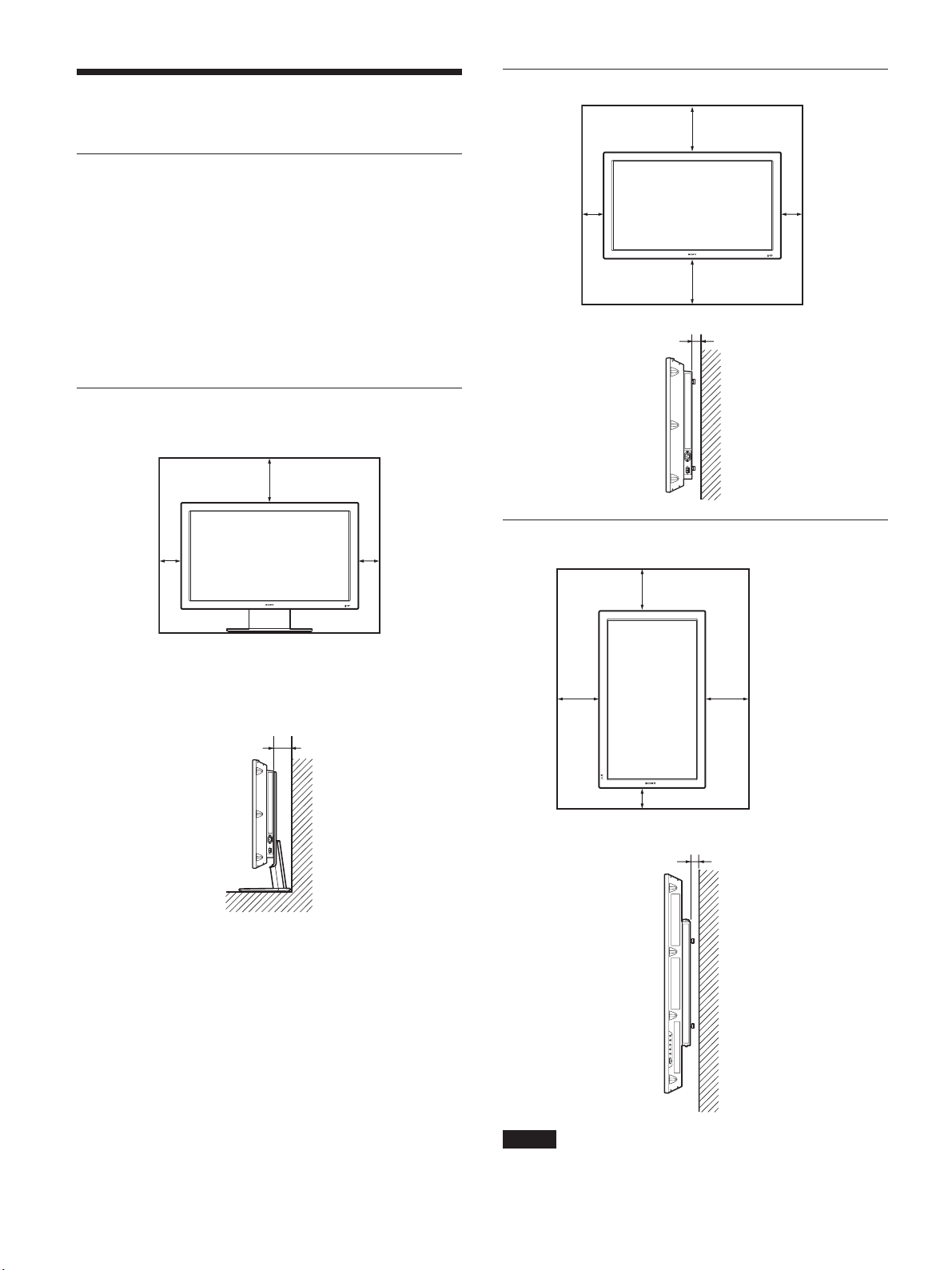
周囲に充分なスペースをとる
内部の温度上昇を防ぐためディスプレイの周 囲 に以下に示す以
•
上の距離をあけてください(下図参照)。
水平方向で使用する場合、スタンドには 、専用スタンドSU-42FW
•
(別売り)をご使用ください。
通電中は高温になる部分があり、やけどの原因となります。通電
•
中やスタンバイにした 直後 は、本機の上面、後面には手を触れ
ないでください。
スタンド(別売り)を使用する場合
前面
20
10
10
水平方向で使用する場合
前面
10
側面
垂直方向で使用する場合(
前面
25
10
25
5
単位
FWD-42PV1P
: cm
)
側面
10
単位
: cm
側面
25
20
25
10
5
16
(JP)
単位
: cm
ご注意
FWD-42PV1PにオプションスピーカーSS-SP42FWを取り付けるこ
とは できませ ん 。
Page 17
使用上のご注意
/
接続
画面の焼き付きや残像についてのご注意
次の1〜5のような 画像を画面上に一定時間表示し続けると、
部分的に焼き付きや残像が発生することがあります。これはプラズ
マディスプレイパネルの特性上起こるものであり、以下のA〜D
の操作を行うことに より、焼き付 きや残像を低減できます。
焼き付きや残像が発生しやすい状態
1 上下に帯が表示されるワイド映像(レターボックス映像)
2 画面横縦比 4:3 の映像
3 ゲーム映像
4 DVD のメニュー画面
5 地上・BS・110度CSチューナー、ビデオデッキなどの 映 像に
切り換えたときに 表示されるチャンネル番号やメ ニューなど
焼き付きや残像を低減させるために
A 画面の焼き付きや残像を低減させるため、「スクリーン セー
バー」を使うことを お 勧 めします 。
B 地上・BS・110度CSチューナー、ビデオデッキなどの 映 像に
切り換えたときに画面に 表 示されるチャンネ ル番号やメニュー
などは、地上・BS・110度CSチューナー、ビデオデッキ側の
画面表示操作で表示を消すことをお勧めします。詳しくは、
お使いの地上・BS・110度CSチューナー、ビデオデッキなど
の取扱説明書をご覧ください。
C 画面の「明るさ」を暗くして、画面モードを「ワイドズーム」や
「フル」で表示すると、画面の焼き付きや残像が起こりにくくな
ります 。
D 画面の焼き付きや残像が軽度のときは、「スクリーンセーバー」
の「画像反転」、「オールホワイト」機能を使って目立たなくす
ることが で きま すが 、一度起こった焼き付きや残像は完全に
は消えません。
接続
接続上のご注意
各機器の電源を切ってから接続を行ってください。
•
接続ケーブルはそれぞれの端子の形状に合った正しいものをお
•
選びください。
プラグはしっかり差し 込 んでください 。接続が悪いとノイズの原
•
因となります。
コードを 抜くときは必ずプラグを持って抜いてください。
•
接続の詳細については、各機器の取扱説明書をご覧ください。
•
電源コードのプラグは、ACINソケットに 、まっ すぐ 突 き当 た るま
•
で差し込んでください。
付属のACプラグホルダーは、使用する電源コードのプラグが確
•
実に固定できる方を選んでお使いください。
スピーカーの接続
別売りのスピーカー(SS-SP42FW)を接続して、より臨 場 感あふれ
る映像をお楽しみ い ただけます。スピー カー の接 続 について詳し
くは、スピ ーカーに付属の取扱説明書をご覧の上、正しく接 続して
ください。
また、スピーカー コードのまとめ方は、この取扱説明書の「ケーブ
ルホルダーを使う」(18(JP)ページ)をご 覧ください。
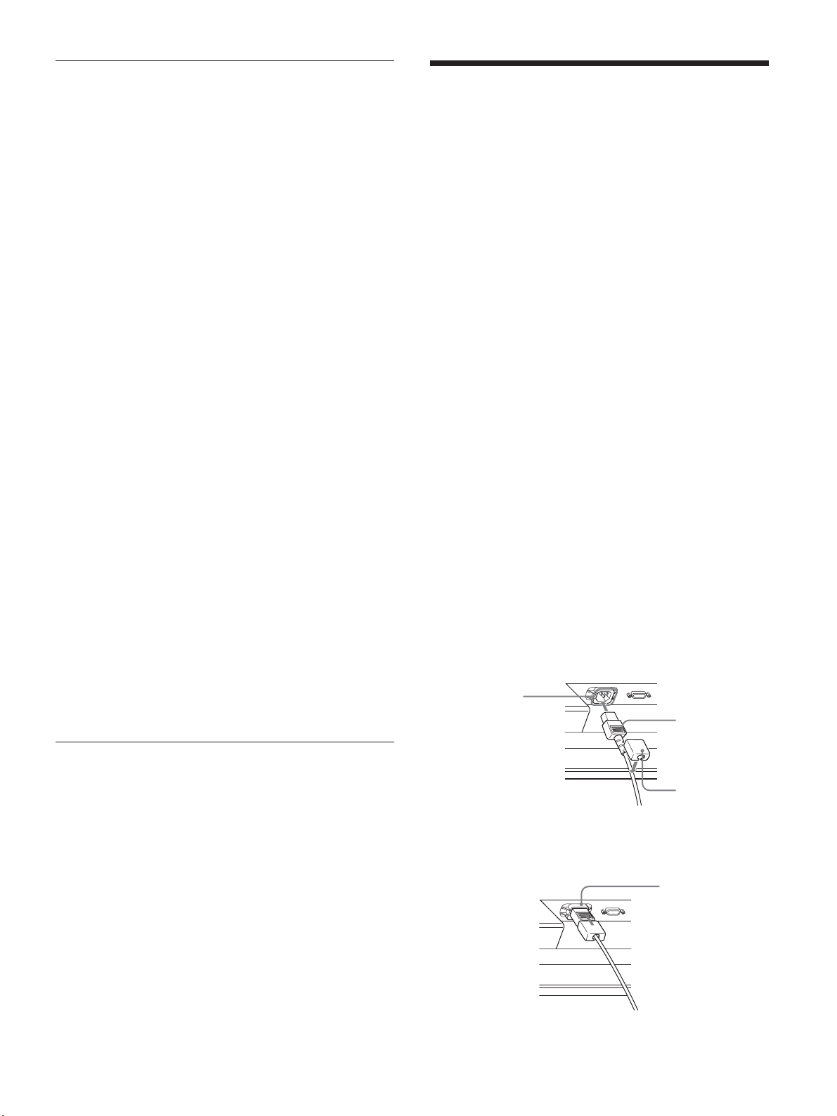
電源コードの接続
1 電源コードを 下面 の ACINソケットに 差し 込 み 、ACプラグホル
ダー(付属)を電源コードに取り付 ける。
ソケット
AC IN
電源コード
スクリーンセーバー(画像反転)についてのご
注意
表示画面が写真のネガフィルムのようになった場合、「スクリー ン
セーバー」の「画像反転」が「自動」もしくは「入」に設定されて
いる可能性があります。通常の画像に戻すためには、「切」を選ぶ
か「自動」にて時刻の設定をしてください。
画像反転とは、焼き付いてしまった画像を表示したまま、画面の
色合いを反転し(例:白→黒、黒→白)補正します。画像反転中
は写真のネガフィルムのような画像になりますが、故障ではありま
せん。
プラグ
AC
ホルダー
2 ACプラグホルダーをスライドさせて、本体側の ACINソケッ
トカ バ ーに は め込む。
AC IN
ソケットカバー
17
(JP)
Page 18
接続
電源コードをはずすには
ACプラグホルダーのつめをはさみ、ロックを 解 除 し て からプラグ を
つかみ、電源コードをは ずしてください。
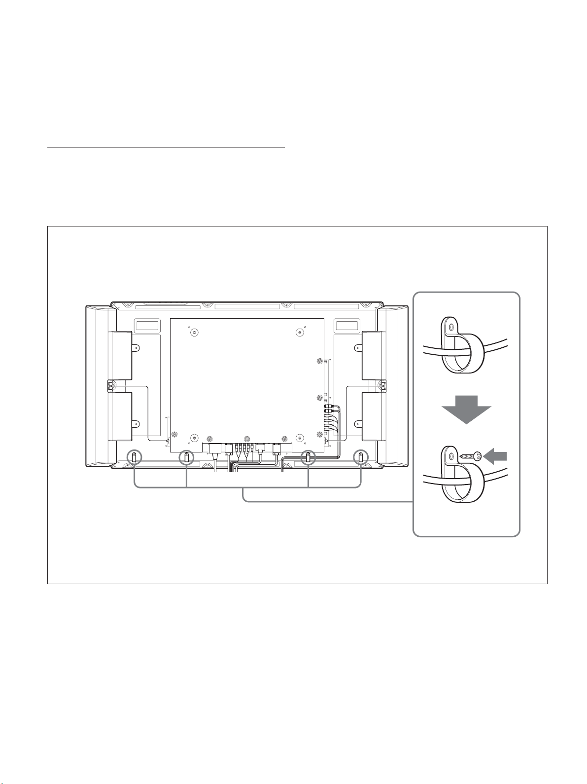
ケーブルを処理する
ケーブルホルダーを使う
付属のケーブルホルダー(× 4)を使って、ケーブル類をすっきり
とまとめることが できます 。ケーブルホルダーは、以下のように取
り付けます。
本機後面
1
2
18
(JP)
Page 19
メニューで行う調整と設定
メニューで行う調整と設定
4 M/mボタンで設定や調整値を選び、ENTER ボタンを押す。
設定が決まり、元 の メニューに 戻ります 。
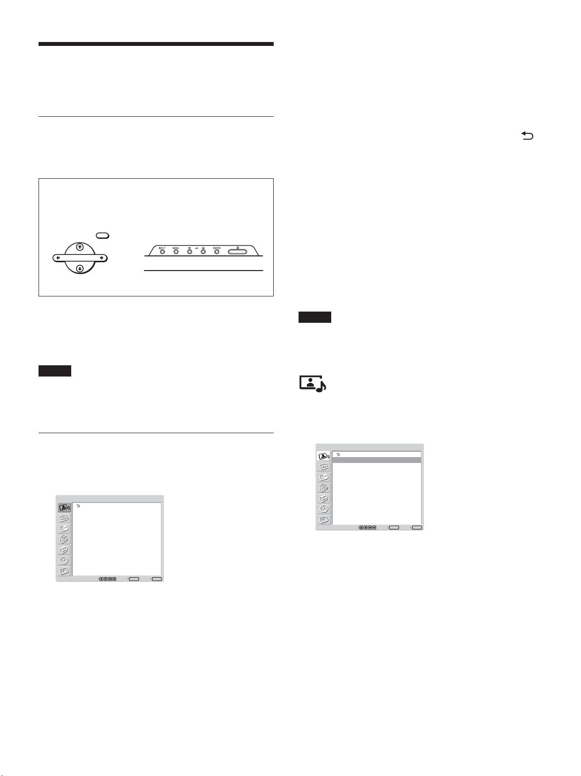
メニューの操作
メニュー操作ボタン
メニューは、リモ コンまた はディスプレイ本体のコントロール ボタン
部のメニュー操作ボタンを使って操作します。
リモコン上のメニュー
操作ボタン
MENU
ENTER
ディスプレイのコントロールボ
タン部のメニュー操作ボタン
この取扱説明書ではリモコンを使って操作の説明をしています。リ
モコンのM/mボタンおよびENTERボタンは本体のM/mボタンお
よび ENTERボタンと、同じ働きをします。
ご注意
本体には</,ボタンがないため、一部操作が異なる部分があ
ります 。
メニューの操作方法
1 MENUボタンを押す。
メインメニューが表 示されます。
メニュー の 操 作を終 了し、通常の画面に戻るには、MENUボタン
を押します。
ひとつ前の階層に戻るには、M/mボタンでカーソルを動かして
を選び ENTERボタンを押すか、<ボタンを押します。
メニュー表示言語を切り換えるには
メニュー 画面やメッセ ージ の 表示言語を6 か国語の中からお好き
な言語に切り換えることが できます 。
工場出荷時は「ENGLISH」(英語)に設定されています。
◆表示言語の切り換えについて詳しくは、「メニュー表示の言語を選ぶ」
(38(JP)ページ)をご覧ください。
メニューの説明
ご注意
入力信号や設定によって選択や調整ができない項目の文字は濃
いグレーになります。
画質/音質調整メニュー
ディスプレイに表示される映像の画質と音質を調整するメニューで
す。
画質/音質調整
画質モード:
画質調整
音質調整
スタンダード
画質/音質調整
画質モード:
画質調整
音質調整
選択
スタンダード
ENTER終了MENU
決定
2 M/mボタンでカーソル(黄色)を動かして、メインメニューを
決め、ENTERボタンを押す。
次のメニューにカーソルが移動します。
3 M/mボタンでカーソル(黄色)を動かして、設定する項目を
決め、ENTERボタンを押す。
それぞれの項目の設定画面が表示されます。
さらに次 のメニ ューが 表示され た場 合は 、同様に設定する項
目を選 びます。
ENTER終了MENU
決定
選択
画質モード
周囲の明るさや絵柄に合った画質モードを 設 定します 。
◆画質モードについ て詳しくは、「画質を選ぶ」(27(JP)ページ)をご 覧
ください。
(JP)
19
Page 20
メニューで行う調整と設定
画質調整
画像を信号処理により調整するメニューです。
画質モードが「ユーザー1〜3」のとき、お好みの画質に調整する
ことが できま す 。
ご注意
画質モードが「ダイナミック」「スタンダード」のときは調整できませ
ん。
◆画質調整について詳しくは、「画質を調整する」(27(JP)ページ)をご
覧ください 。
音質調整
音質を信号処理により調整するメニューです。
画質モードが「ユーザー1〜3」のとき、お好みの音質に調整する
ことが できま す 。
ご注意
画質モードが「ダイナミック」「スタンダード」のときは調整できませ
ん。
◆音質調整について詳しくは、「音質を調整する」(37(JP)ページ)をご
覧ください 。
ワイド切換
映像のサイズや種類に合わせてワイド表示を切り換えます。
◆ワイド切換について詳しくは、「ワイド切 換を設定する」(31(JP)ペー
ジ)をご覧ください。
画面調整
画像のサイズや位置、ドットを調整するメニューです。
◆画面調整について詳しくは、「画像のサイズや位置を調整する」(32
(JP)ページ)をご 覧ください。
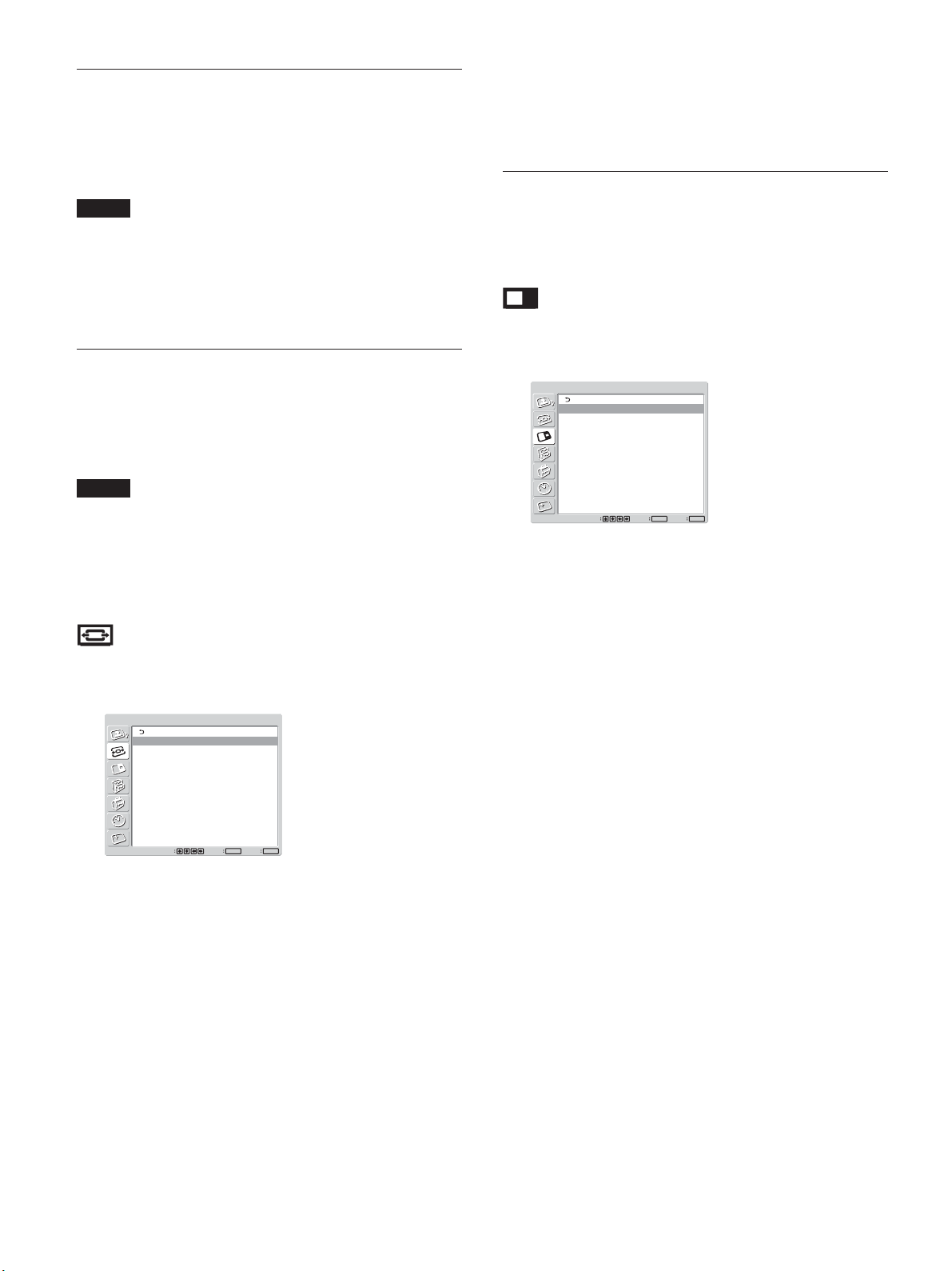
画面メニュー
2
パソコンの映像とビデオの映像など、2種類の映像を同時に表
示させることが できます。
画面
2
画面:
2
操作入替
画サイズ
副画面位置
選択 決定
◆2画面機能について詳しくは、「2つの画面を表示させる」(34(JP)
ページ)をご覧 下さい。
切
MENU
ENTER
終了
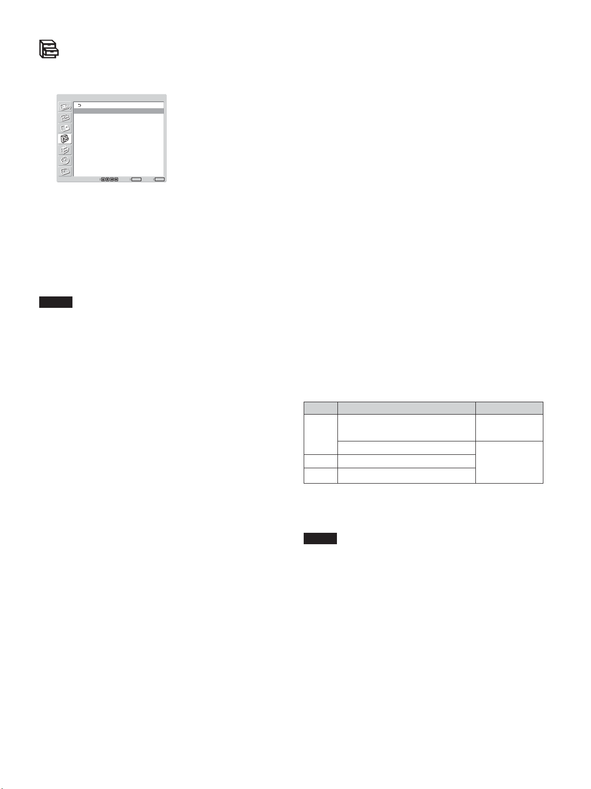
画面モード調整メニュー
画像のサイズや位置を調整するメニューです。
画面モード調整
マルチディスプレイ設定
オートワイド設定
ワイド切換:
画面調整
選択
ワイドズーム
ENTER終了MENU
決定
マルチディスプレイ設定
本機を2×2や 3×3など、複数台接続してビデオウォールなどを
構成するための各種設定を行います。
◆ マルチディスプレイ設定に つ いて詳しくは、「マルチディスプレイの設定
をする」(36(JP)ペ ージ )をご覧ください。
オートワイド設定
オートワイド機 能を設定するメニューです。オートワイド機能とは、
通常のテレビ放送やワイドクリア ビジョン、ワイドスクリーン 画 像な
ど、横縦比の異なる映像の種類に対して最適なワイド切換を選び、
横縦比16:9のワイド画面いっぱいに自動的に画像を拡大する機能
です。
◆オートワイドにつ いて詳しくは、「オートワ イドを設 定 する」(30(JP)ペー
ジ)をご覧ください。
20
(JP)
Page 21
各種切換メニュー
消費電力を減らしたり、各種モードを 設定したりするメニューで す 。
各種切換
消費電力:
スピーカー出力:
クローズドキャプション:
ステータス表示:
カラーマトリクス:
モード:
HD
モード:
RGB
同期モード:
リモートコントロール設定
選択
標準
切
切
切
Y/PB/PR
1080i
DTV
同期信号
ENTER終了MENU
決定
消費電力
節電しながら画面を表示することができます。
標準:節電しない
減:節電する
節電モードを減に すると、画面の明るさを下げて、節電しながら見
ることが できま す。
ご注意
「消費電力:減」のときに電源を切ると、次に電源を入れたとき
•
も「消費電力:減」のままになります。
画質モードで「ユーザー1〜3」を選んでいるときは、「消費電力:
•
減」でも、画質を調整できます。ただし、コントラストや 明るさを上
げると節電にならなくなる場 合があります。
スピーカー出力
入にすると、スピーカー(SS-SP42FW、別売り)から音 が 出ます 。
クローズドキャプション
字幕を画面に表示したいときに使用します。
NTSC信号のみ有効です。
切:字幕を表示しない
CC1〜4
:画像に重ねて字幕を表示する
メニューで行う調整と設定
モード
HD
入力されるH Dアナログコンポーネント信 号 に よってモードを 設定
します。
:1080i の信号を受ける場合
1080i
:1035i の信号を受ける場合
1035i
モード
RGB
RGB信号を出力する機器を接続しているときに、モードを設 定し
ます。
:RGB信号のデジタルチューナーなどを接 続している場合
DTV
:パソコンを接 続している場 合
PC
同期モード
RGB/COMPONENT端子の13 番ピンに入力される信号によっ
て、モードを設 定します 。設定できる信号は、575/50I、480/60Iの
みです。
同期信号:水平信号またはコンポジット同期信号*が入力される
場合
映像信号:映像信号が入力される場合
*コンポジット同期の信号レベルによっては正しく画像が表示され
ない場合があります。その際は、同期モードの設定を変 更し て
ください。
入力信号と同期モードの設定
PIN D-sub
480/60I、575/50I の
13 CompositeVideo
入力信号 同期モード選択
映像信号
CompositeSync
13/14 HSync/VSync
同期信号
2 SyncOnGreen
◆ RGB/COMPONENT 端子のピン配列については、「ピン配列」(48
(JP)ページ)をご 覧ください。
ステータス表示
入にすると、ディスプレイの電源投入時や入力信号が切り換わっ
たとき、入 力されている信号 の種類と画 質 モードを 約5秒間画面
に表示します。
カラーマトリクス
接続している機器からのコンポーネント信号入力時の映像が自然
な色あいになるように設定します。
◆カラーマトリク スに つ い て詳しくは、「カラーマトリクス を 調整する」
(38(JP)ページ)をご覧ください。
ご注意
「同期信号」しか選べない入力があります。この場 合は 1 3ピンに
•
「映像信号」を入力しても画 像は表示されません。水平・垂直同
期信号を13、14ピンに入力するか、SyncOnGreen信号をRGB
に入力してください。
SyncOnGreenでは同期信号に設定しないと画像が表示されま
•
せん。
同期モードの映像信号に対応できるのはINPUT2 のみです。
•
オプションボード入力では、同期モードの設 定はできません。
•
本機はコンポジットシンクおよび 576/60P の 3 値シンクには対応
•
していません。
同期モードで「映像信号」を選択した場合、2画面への切り換え
•
はできません。
(JP)
21
Page 22
メニューで行う調整と設定
リモートコントロール設定
リモコンの操作に関する設定を行います。
インデックス番号
ディスプレイ本体のインデックス番号を設定します。
ご注意
この項 目を設定する場合は、ディスプレイ本体のボタンを使用して
ください。リモ コンでは設定できません。
◆インデックス番号について詳しくは、「特定のディスプレイをリモコンで 操
作する」(44(JP)ペ ージ )をご覧ください。
コントロールモード
リモ ートコントロール の モードを 切り換えます 。
本体+リモコン:ディスプレイに付属しているリモコンから操 作 す
るとき。
本体のみ:リモ コンから 操 作しな いとき。(リモコンからは操作で
きなくなります 。ディスプレイ本体のボタンからのみ設定でき
ます。)
リモコン のみ:本体から操作しないとき。(本体からは操作できな
くなります 。リモ コンからの み設定できます。)
ご注意
この項 目を設定するときは 、使っている操作ボタンによって選 べる
モードが変わります。
リモコン の ENTERボタンを使って設定するときは、「本体+リモコ
ン」と「リモコン の み 」が選べます。
本体のENTERボタンを使って設定するときは「本体+リモコン」
と「本体のみ」が選べます。
カラー方式
ビデオ信号のカラー方式を選びます。
自動:カラー方 式を自動で設定します。
:NTSC の映像を見る場合
NTSC
NTSC4.43
PAL
SECAM
PAL-M
PAL-N
PAL60
:NTSC4.43 の映像を見る場合
:PAL の映像を見る場合
:SECAM の映像を見る場合
:PAL-M の映像を見る場合
:PAL-N の映像を見る場合
:PAL60 の映像を見る場合
オートシャットオフ
「入」にすると、コンポ ーネント入 力、VIDEO 入力に信号が入力さ
れない状態が約5分続くと、本 機 は自動的にスタンバイ状態にな
ります 。DVI 入力、RGB入力に信号が入力されない状態が約 30
秒続くと、自動的にパワーセービング状態になります。スタンバイ
状態のときは1POWER( パワー)スイッチまたはリモコンの
POWERONスイッチを 押 すと、電 源 が入ります。
パワーセービング状態のときは、信号が入力されると自動的に電
源が入ります。
自動画面調整
「入」にすると、各入力信号について設定した調整値(サイズ、位
置など)がメモリーに保存され、次にその信号に切り換えたときに、
最後の調整値が自動的に適用されます。
「切」にすると、入力信号を切り換えても自動調整されず、工場出
荷時の調整値が適用されます。
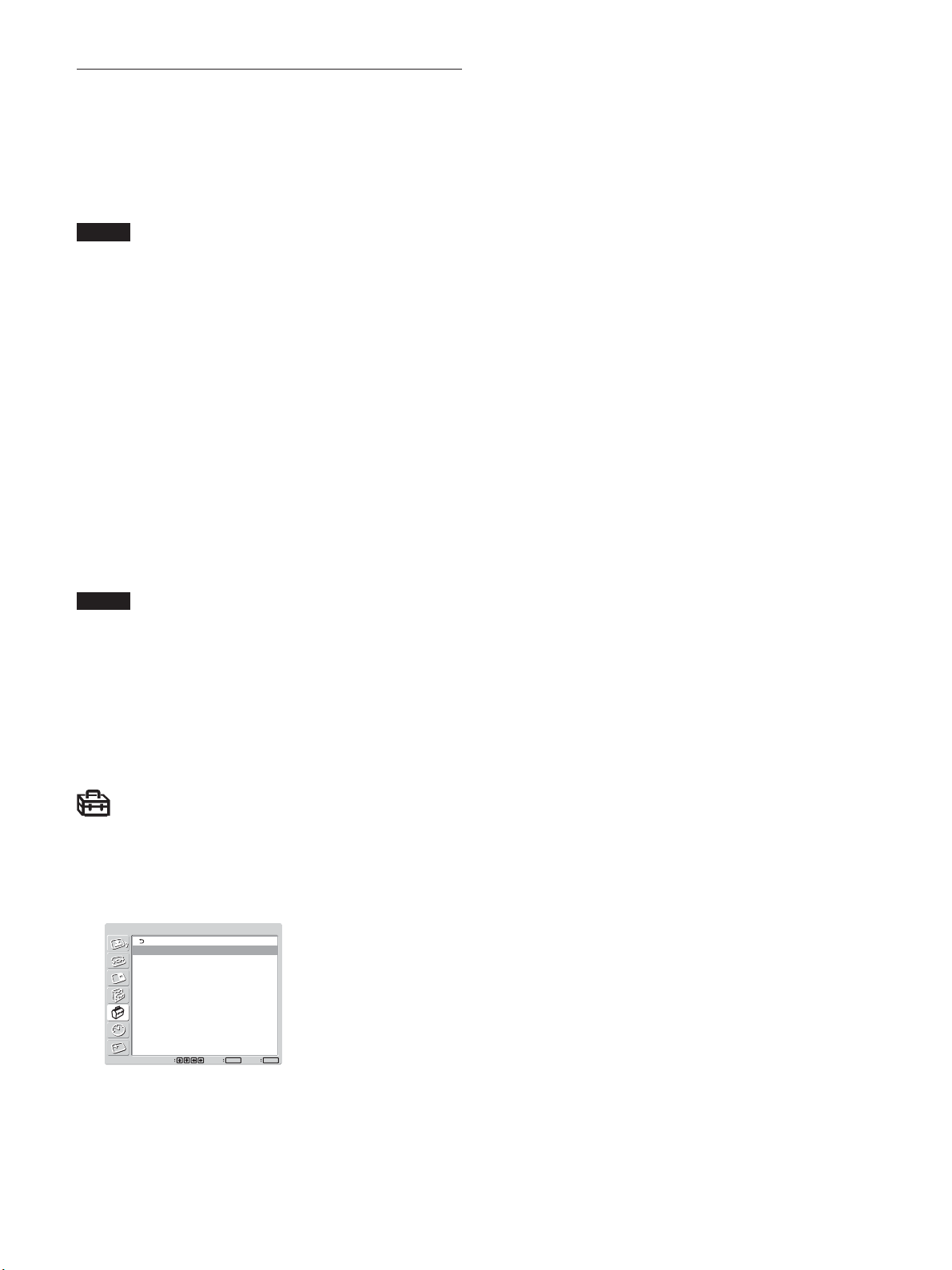
初期設定/インフォメーションメ
ニュー
メニュー表示の言語や映像ソースを選んだり、通電時間などの情
報を表 示したりするメニューです。
初期設定/インフォメーション
言語:
カラー方式:
オートシャットオフ:
自動画面調整:
インフォメーション
IP Address Setup
Speed Setup
選択
言語
メニューを 表 示する言語を日 本語、英語、ドイツ語、フランス語 、ス
ペイン語、イタリア語から選びます。
◆言語について詳しくは、「メニュー表示の言語を選ぶ」(38(JP)ペ ー
ジ)をご覧ください。
(JP)
22
日本語
自動
切
入
ENTER終了MENU
決定
Page 23
インフォメーション
メニューで行う調整と設定
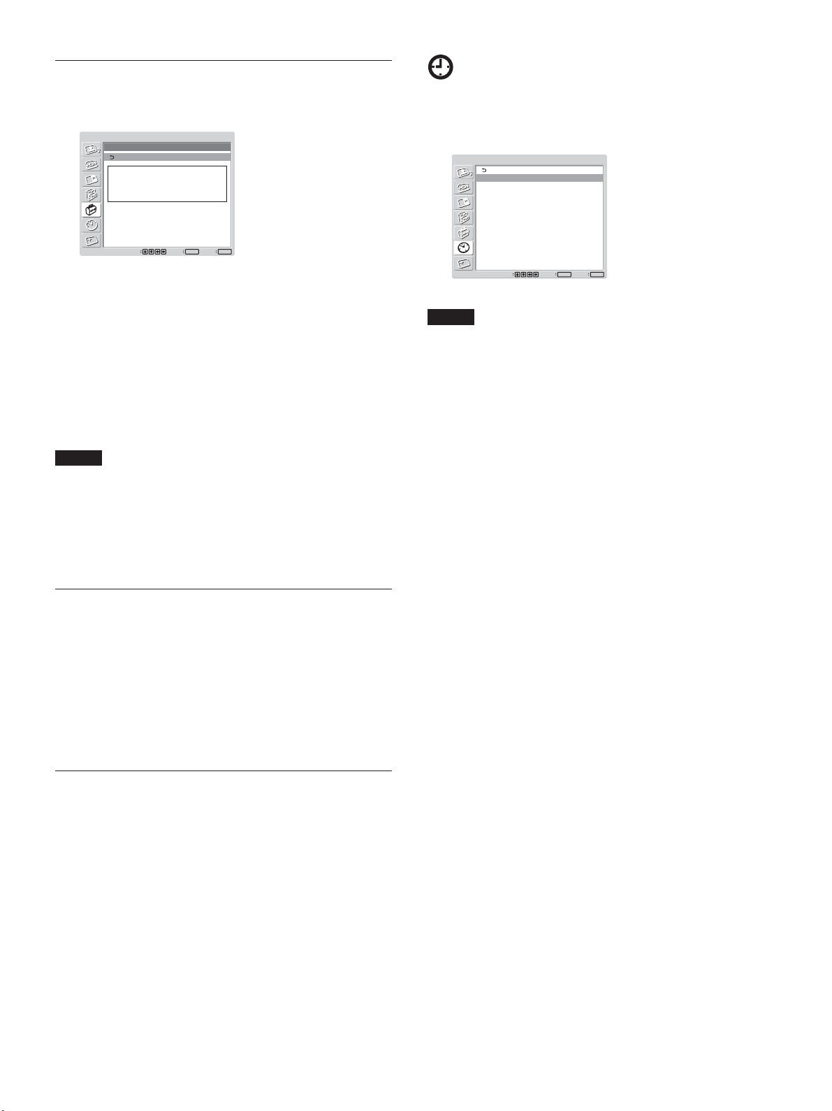
タイマー/時計設定メニュー
ディスプレイ本体の内部状態を表示します。
初期設定/インフォメーション
インフォメーション
機種名:
シリアル番号:
累積通電時間:
ソフトウェアバージョン:
選択
**********
********
******
****/****
ENTER終了MENU
決定
機種名
機種名を表示します。
シリアル番号
シリアル番号を表示します。
累積通電時間
電源を入れていた累積通電時間を1 時間単位で表示します。
ご注意
スタンバイ状態は累積通電時間に含まれません。
ソフトウェアバージョン
システムソフトウェア のバージョンを 表示します。
時刻やタイマーの設定、時刻の表示、電源入/切の管理を設定
するメニューです。
タイマー/時計設定
時刻設定
時計表示:
電源タイマー
選択
切
ENTER
決定
MENU
終了
ご注意
工場出荷状態では、時刻と曜日は設定されていません。
時刻設定
時刻と曜日を設定するときに使用します。
◆時刻設定について詳しくは、「時刻と曜日を設定する」(39(JP)ペ ー
ジ)をご覧ください。
時計表示
入にすると画面に設定した時刻が表示されます。
◆時計表示について詳しくは、「時計を表示する」(39(JP)ページ)をご
覧ください 。
IP Address Setup (IP
アドレス設定)
本機とオプションアダプターBKM-FW32(NetworkManagement
Adaptor)の間で通信を行うためのIPアドレスを 設 定しま す 。
:IPアドレ スを自動取得する。
DHCP
Manual
:IP アドレスを マニュア ルで設定する。
◆詳しくは「IPアドレス お よ び通信速度を設定する」(43(JP)ページ)を
ご覧ください。
Speed Setup
(通信速度設定)
本機とオプションアダプターBKM-FW32(NetworkManagement
Adaptor)の間の通信速度を設定します。
◆詳しくは「IPアドレス お よ び通信速度を設定する」(43(JP)ページ)を
ご覧ください。
これらの項目は、COMMUNICATIONスロットに オプションアダプ
ター BKM-FW32(NetworkManagementAdaptor)を装着した
場合のみメニューに表示されます。
電源タイマー
時間を自由に設定して、自動的に電源を入/切するようにします。
◆電源タイマーについて詳しくは、「電源タイマー機能」(39(JP)ページ)
をご覧ください。
23
(JP)
Page 24

メニューで行う調整と設定
スクリーンセーバーメニュー
長時間にわたって同じ画面を映したりする場合に生じる画 面の焼
き付きや残像を補 正したり軽減するときに使用します。
スクリーンセーバー
画像反転:
自動表示位置移動
オールホワイト:
バックグラウンド:
自動明るさ低減:
切
切
グレー
入
ENTER終了MENU
選択
決定
画像反転
画像の色あいを反転させます。
自動表示位置移動
一定の時間がたつと画像の表示位置を自動的に移動させます。
オールホワイト
全画面を白く表示して、すでに焼き付きが発生している部分との
差を小さくします 。
バックグラウンド
アスペクト比4:3画面を映すときなど、映像の出ないバックグラウン
ドの色を設定します。
自動明るさ低減
静止画の表示が5分以上続くと、徐 々に 輝 度を 落として焼き付き
を軽減します。
◆スクリーンセーバーメニューの 各 モードについて詳しくは、「スクリーン
セーバー機能 」(40(JP)ペ ージ )をご覧ください。
24
(JP)
Page 25
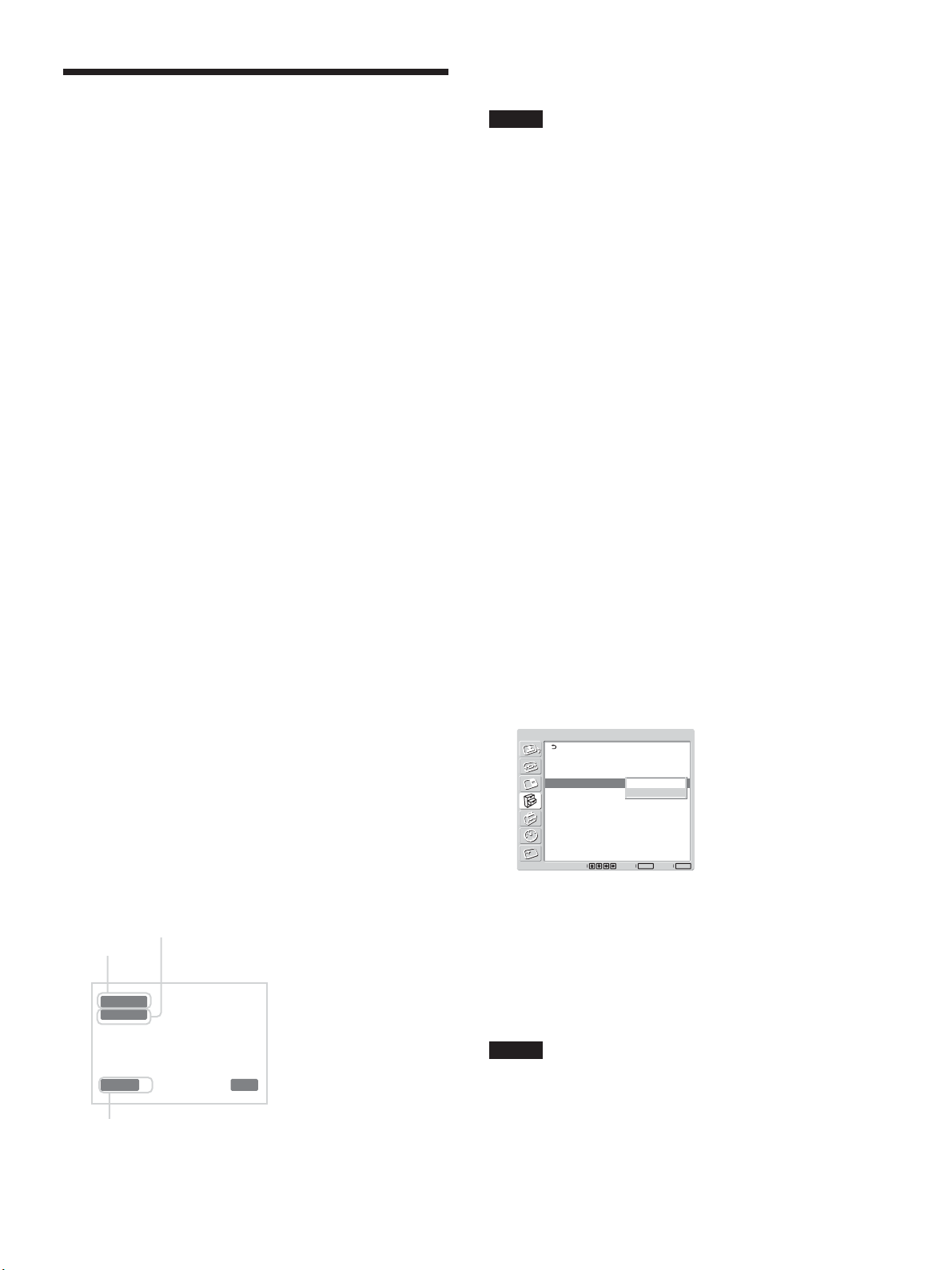
画像を見る
準備
ディスプレイの電 源を入れておきます 。
•
接続した機器の電源を入れ、映像ソースを再生します。
•
電源投入時または入力切り換え時に入力信号の種類と画質モー
•
ドを画面に表示させたいときは、各種切換メニューの「ステータ
ス表示」を入にしておきます。
メニュー表示は日本語以外の言語にすることもできます。
•
◆詳しくは、「メニュー表示の言語を選ぶ」(38(JP)ペ ージ )をご覧く
ださい。
入力信号を切り換える
画像を見る
本体のINPUTボタンで入力を切り換えることもできます。
ご注意
ディスプレイへ のビデ オ入力信号は、TBC(タイムベースコレク
•
ター)付きの入力ソース機 器 からの入力をおすすめします。TBC
のかかっていない信号を入力すると、同期の乱れにより映像が
消えることがありま す 。
同じフォーマットの信 号を 複数の系統から入力している場合、画
•
質モードの設定は最新の設定値になります(同フォーマットの
み)。
入力信号と画質モードの情報とディス
プレイの設定状態の表示について
Input1 DVI
:INPUT1端子に接続した機器の入力信号
(デジタルRGB信号)を選ぶ場合。
Input2 RGB
:INPUT2 端子に接続した機器の入力信号
(アナログ RGB信号)を選ぶ場合。
Input2 Component
:INPUT2端子に接続した機器の入
力信号(コンポーネント信号)を選ぶ場合。
Option1 Video
:OPTION1 スロットに 接 続し た 機器の入
力信号(ビデオ信号)を選ぶ場合。
Option1 S Video
:OPTION1スロットに 接 続し た機器の
入力信号(Sビデオ信号)を選ぶ場合。
Option1 RGB
:OPTION1スロットに 接 続し た 機器の入力
信号(アナログ RGB信号)を選ぶ場合。
Option1 Component
:OPTION1 スロットに 接 続し た 機
器の入力信号(コンポーネント信号)を選ぶ場合。
リモコン の INPUT1、INPUT2、OPTION1ボタンを押して、入
力を切り換えます。選んだ入力に複数のフォーマットを接続で
きるときは 、ボタンを 押 す た びに表示が切り換 わります 。
例)INPUT2ボタンを押すたびに、「Input2RGB」、「Input2
Component」に切り換わる。選んだ入力信号は、ディス
プレイ画 面に 表 示されます。
電源投入時または入力切り換え時に、入力信号と画質モードの情
報が約5秒間画面に表示されます。
情報を画面に表示しないようにするときは、以下の手順に従って
設定してください。
1 MENUボタンを押す。
メインメニューが表 示されます。
2 M/mボタンで「各種切換」を選び、ENTERボタンを押す。
各種切換メニューが表示されます。
3 M/mボタンで「ステータス表示」を選び、ENTERボタンを 押す。
以下の画面が表示されます。
各種切換
消費電力:
スピーカー出力:
クローズドキャプション:
ステータス表示:
カラーマトリクス:
モード:
HD
モード:
RGB
同期モード:
リモートコントロール設定
選択
標準
切
切
切
切
入
Y/PB/PR
1080i
DTV
同期信号
決定
ENTER
MENU
終了
入力系統
Input1 DVI
640x480/60
ダイナミック
画質モード
カラー方式または解像度/垂直周波数
15 : 07
4 M/mボタンで「ステータス表示」を切にし、ENTER ボタンを
押す。
ステータス表示させるには
手順2で「ステータス表示」を入にし、ENTERボタンを押します。
(工場出荷時は入に設定されています。)
ご注意
本機に付属しているリモコンのDISPLAYボタンを押して、いつでも
必要なときに入力信号の情報および画質モードを表 示 することもで
きます 。
(JP)
25
Page 26
画像を見る
入力プリセット信号
信号名称 カラー方式または水平/
垂直周波数表示
コンピューター信号
1 VGAa)-1(VGA350) 31.5kHz 70Hz
2 640×480@60Hz 31.5kHz 60Hz
3Mac
4 VGA(VGATEXT) 31.5kHz 70Hz
5 800×600@60Hz(VESAc)STD) 37.9kHz 60Hz
6 Mac16" 49.7kHz 75Hz
7 1024×768@60Hz(VESASTD) 48.4kHz 60Hz
8 1024×768@75Hz(VESASTD) 60.0kHz 75Hz
9 1024×768@85Hz(VESASTD) 68.7kHz 85Hz
10 1152×864@75Hz(VESASTD) 67.5kHz 75Hz
11 Mac21" 68.7kHz 75Hz
12 1280×960@60Hz(VESASTD) 60.0kHz 60Hz
13 1280×1024@60Hz(VESASTD) 64.0kHz 60Hz
14
1600×1200@60Hz(VESASTD)*75.0kHz 60Hz
15 848×480@60Hz(CVTd)) 29.8kHz 60Hz
16 848×480@75Hz(CVT) 37.7kHz 75Hz
17 848×480@85Hz(CVT) 43.0kHz 85Hz
18 1280×720@60Hz(CVT) 44.8kHz 60Hz
19 1280×768@60Hz(CVT)
20 1280×768@75Hz(CVT) 60.3kHz 75Hz
21 1280×960@60Hz(CVT) 59.7kHz 60Hz
22 1360×768@60Hz(CVT)
23 800×600@60Hz(CVT) 37.4kHz 60Hz
24 1024×768@60Hz(CVT)
25 1280×1024@60Hz(CVT) 63.7kHz 60Hz
26 1400×1050@60Hz(CVT)
27 1600×1200@60Hz(CVT)
SDTV/HDTV
1 PAL PAL
2 NTSC NTSC
3 SECAM SECAM
4 NTSC4.43 NTSC4.43
5 PAL60 PAL60
6 PAL-M PAL-M
7 PAL-N PAL-N
8 575/50i 575/50I
9 480/60i 480/60I
10 1080/24psf 1080/48I
11 1080/50i 1080/50I
12 576/50p 576/50P
13 480/60p 480/60P
14 1080/60i 1080/60I
15 720/60p 720/60P
16 720/50p 720/50P
b)
13" 35.0kHz 67Hz
**
**
**
47.8kHz 60Hz
47.7kHz 60Hz
47.8kHz 60Hz
*
65.3kHz 60Hz
*
74.5kHz 60Hz
a) VGAは米国InternationalBusinessMachinesCorporationの登録商
標です。
b) Mac(Macintosh)は AppleComputer,Inc.の登録商標です。
c) VESAは VideoElectronicsStandardsAssociationの登録商標です。
d) VESACoordinatedVideoTiming
ご注意
HDTV信号を入力する場合、 同期信号は3値同期信号を
•
INPUT2、BKM-FW12のRGB/COMPONENT端子(D-sub15
ピンコネクター)の 2 番ピンに入力してください 。
本機でDVD信号を入力した場合、画像の色を薄く感じたら、画
•
質調整メニューの「色の濃さ」でお好みの色の濃さに調整して
ください。
位相を再調整すると解像度が低下します。
•
Macの信号は、デジタル RGB信号入力では、保証されません。
•
・*の信号は、デジタルRGB 信号入力端子に入力できません。
・**の信 号のそ れ ぞ れを自 動判別できません。「画面モード調
整」メニューの中 の「画質調整」にある「自動調整」を実行する
たびに、それぞれに最 適な設定が順番に適用されます。最適な
設定でご使用ください。
入力信号/ディスプレイ設定情報の画面表示
画面表示 意味
640×480/60(例) コンピューター信号が入力されています。
480/60i(例) コンポーネント信号が入力されています。
NTSC(例) NTSC信号が入力されています。
標準信号ではありま 受像できない信号が入力されています。
せん
信号が入力されていま 入力信号がありません。
せん
INPUT1DVI INPUT1端子の入力モードはデジタルRGB
です。
INPUT2RGB INPUT2端子の入力モードはアナログ RGB
です。
INPUT2Component INPUT2端子の入力モードはコンポーネン
トビデオです。
Option1Video OPTION1スロットの 入力端子の入力モー
ドはコンポジットビ デ オ で す 。
Option1SVideo OPTION1 スロットの入力端子の入力モー
ドはSビデオです。
Option1RGB OPTION1スロットの入力端子の入力モー
ドはアナログRGB です。
Option1Component OPTION1スロットの入力端子の入力モー
ドはコンポーネントビ デオです。
26
(JP)
Page 27
画質を選ぶ/画質を調整する
画質を選ぶ
映像の種類や周囲の明るさに合わせて画質を選ぶことができま
す。
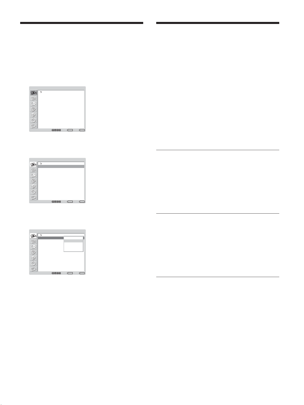
1 MENUボタンを押す。
メインメニューが表 示されます。
画質/音質調整
画質モード:
画質調整
音質調整
選択
2 M/mボタンで「画質/音質」を選び、ENTERボタンを押す。
画質/音質調整メニューが表示されます。
画質/音質調整
画質モード:
画質調整
音質調整
選択
スタンダード
ENTER終了MENU
決定
スタンダード
ENTER終了MENU
決定
画質を調整する
画像を見ながら、コントラスト、明 るさ、色 の 濃 さ、色あいなどを調
整することができます。また、入力信号ごとに調整を行い、調整値
をメモリーすることが できます。
画質モードを「 ユーザー 1 〜 3 」の いずれかにしてください。
コントラスト、明るさ、
色の濃さ、色あいなどを調整する
MENUボタンを押してメインメニューを表示し、画質調整メニュー
から調 整した い項目に応じて、「コントラスト」、「明るさ」、「色の濃
さ」、「色あい」、「シャープネス」、「NR(ノイズリダクション)」、「ダ
イナミックピ クチャー 」、「色温度」、「ガンマ補正」を調整します。
コントラスト
M/mボタンで「コントラスト」を選び、ENTERボタンを押し、M/m/
</,ボタンでコントラストを調整し、ENTER ボタンを押す。
最小(0)〜最大(100)の範囲で設定できます。
,:コントラストが 強くなる
M
/
<:コントラストが 弱くなる
m
/
3 M/mボタンで「画質モード」を選び、ENTERボタンを押す。
以下の画面が表示されます。
画質/音質調整
画質モード:
画質調整
音質調整
選択
ダイナミック
スタンダード
ユーザー
1
ユーザー
2
ユーザー
3
ENTER終了MENU
決定
4 M/mボタンで画質を選ぶ。
ダイナミック:映像の輪郭とコントラストを最大限に上げた、メ
リハリの 強 い 画 質に なります 。
スタンダ ード:適度なコントラストと輪郭強調によりきめ 細か い
質感のあるリア ル な 画 質 に なりま す 。
ユーザー
:画質調整メニューからお好みの画質を自由
1〜3
に設定できます。
5 ENTERボタンを押すと、画質/音質調整メニューに戻りま
す。
明るさ
M/mボタンで「明るさ」を選び、ENTERボタンを押し、M/m/</
,ボタンで画像の明るさを調整し、ENTERボタンを押す。
最小(0)〜最大(100)の範囲で設定できます。
,:画像が明るくなる
M
/
<:画像が暗くなる
m
/
色の濃さ
M/mボタンで「 色 の 濃さ」を選び、ENTER ボタンを押し、M/m/
</,ボタンでクロマを調 整し、ENTER ボタンを押す。
最小(0)〜最大(50)の範囲で設定できます。
,:色が濃くなる
M
/
<:色が薄くなる
m
/
27
(JP)
Page 28
画質を調整する
色あい
M/mボタンで「色あい」を選び、ENTERボタンを押し、M/m/</
,ボタンで色あいを調 整し、ENTERボタンを押す。
左(50)〜右(50)の範囲で設定できます。
,:画像が緑がかる
M
/
<:画像が赤みがかる
m
/
シャープネス
M/mボタンで「シャープネス」を選び、ENTERボタンを押し、M/
m/</,ボタンで画像のシャープネスを調整し、ENTERボタン
を押す。
最小(0)〜最大(20)の範囲で設定できます。
,:画像をくっきりと表示する
M
/
<:画像をやわらかく表示する
m
/
(ノイズリダクション)
NR
映像のざらつきや色ノイズを軽減することができます。
ダイナミックピクチャー
白をより白く、黒をより黒くしてコントラストを強めます。
1 M/mボタンで「ダイナミックピク チ ャー」を選び、ENTERボタ
ンを押 す。
以下の画面が表示されます。
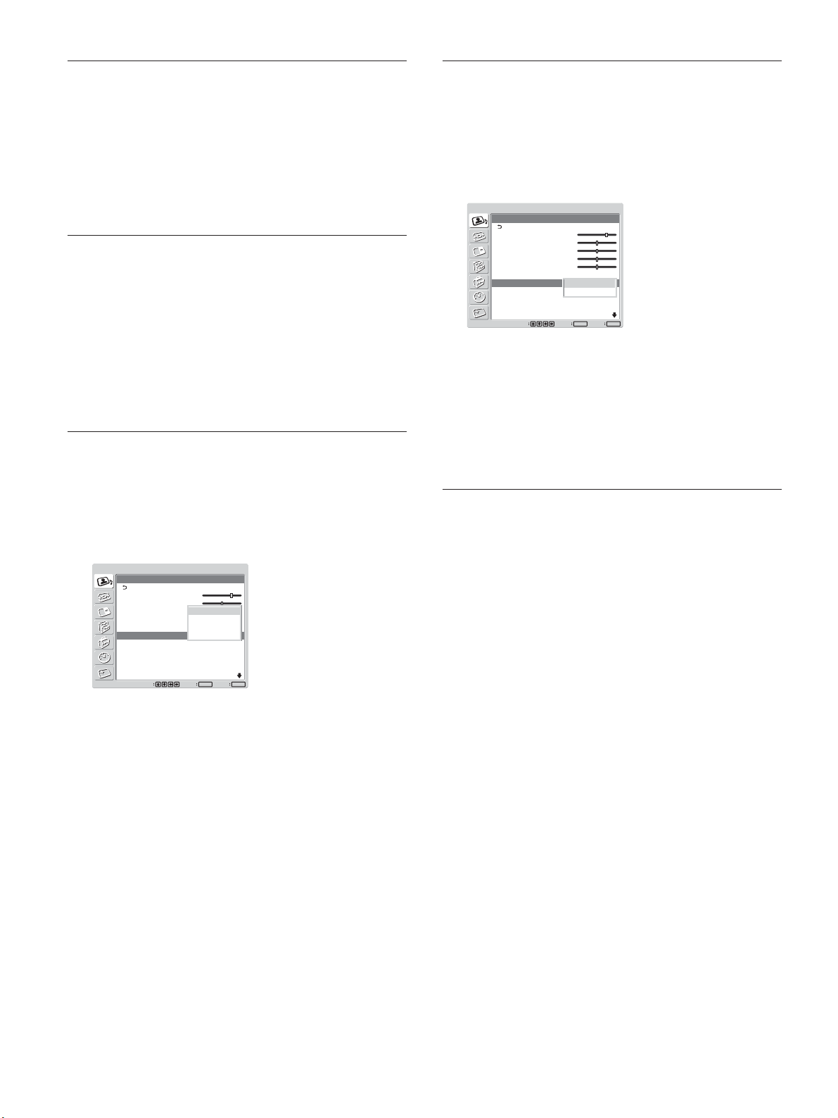
画質/音質調整
画質調整
コントラスト:
明るさ:
色の濃さ:
色あい:
シャープネス:
NR:
ダイナミックピクチャー:
色温度:
選択
70
50
50
0
10
切
切
切
中
入
ENTER終了MENU
決定
2 M/mボタンでダイナミックピ ク チ ャー の モ ードを選 ぶ。
切:ダイナミックピ クチャー 機 能 を 使 わな い
入:ダイナミックピ クチャー 機 能 を 使う
3 ENTERボタンを押すと、画質調整メニューに戻ります。
1 M/mボタンで「NR」を選び、ENTER ボタンを押す。
以下の画面が表示されます。
画質/音質調整
画質調整
コントラスト:
明るさ:
色の濃さ:
色あい:
シャープネス:
NR:
ダイナミックピクチャー:
色温度:
選択
70
50
切
25
低
0
中
5
高
切動
切
中
ENTER終了MENU
決定
2 M/mボタンで NR のモードを 選ぶ 。
切:映像信号をそのまま表示する
低:NR 処理を弱く設定するとき
中:NR 処理を中程度に設定するとき
高:NR 処理を強く設定するとき
3 ENTERボタンを押すと、画質調整メニューに戻ります。
色温度
色温度を設定します。「高」「中」「低」のほか、各ゲインを 好 みに
合わせて細かく調整することもできます。調整した色温度は、3つ
まで登録できます。
1 M/mボタンで「色温度」を選び、ENTERボタンを押す。
2 M/mボタンで色温度を選び、ENTER ボタンを押す。
高:色温度を高く設定するとき
中:色温度を中程度に設定するとき
低:色温度を低く設定するとき
Color1〜3
「高」「中」「低」を選んだ場合には、画質調整メニューに戻り
ます。
「
Color1〜3
(1) M/mボタンで設定したいゲインを 選び、ENTERボタンを
押す。
(2) M/m/</,ボタンでゲインを調 整し( − 15〜+15)、
ENTERボタンを押す。
<ボタンを押 すと、色温度メニュー画面に戻ります。
:各ゲインを細 かく設定するとき
」を選んだ場合
28
(JP)
Page 29
画質を調整する
ガンマ補正
映像の明暗部分のバランスを自動的に調整することができます。
1 M/mボタンで「ガンマ補正」を選び、ENTERボタンを押す。
以下の画面が表示されます。
画質/音質調整
画質調整
ガンマ補正:
標準
選択
高
中
低
ENTER終了MENU
決定
2 M/mボタンでガンマ補正のモードを選 ぶ。
高:ガンマ補 正を強くかけるとき
中:ガンマ補 正を中 程 度にかけるとき
低:ガンマ補 正を弱くかけるとき
3 ENTERボタンを押すと、画質調整メニューに戻ります。
ご注意
RGB信号を入力している場合、色あいと色の濃さは調整できま
•
せん。
コンポ ー ネント信 号を 入 力し て いる場合、色あいは調整できませ
•
ん。
PAL、PAL-M、PAL-N、PAL60および SECAM 方式の入力信号
•
の場合、色あいは調整できません。
白黒信号を入力しているときは、色あいは調整できません。
•
調整した画質を出荷時の設定値に戻す
1 画質調整メニューから、M/mボタンで「 標 準」を選び、
ENTERボタンを押す。
以下の画面が表示されます。
画質/音質調整
画質調整
ガンマ補正:
標準
選択
中
取消
実行
ENTER終了MENU
決定
2 M/mボタンで「実行」を選び、ENTERボタンを押す。
画質調整メニューの項目が工場出荷時の設定値に戻ります。
ご注意
色温度のColor1〜3 の設定値はクリアされ ませ ん 。
リセットを中止するには
ENTERボタンを押す前に MENU ボタンを押してください。また
は、M/mボタンで「取消」を選びENTERボタンを押してください。
29
(JP)
Page 30
映像を拡大する
映像を拡大する
映像の種類に合わせて画面いっぱいに拡大表示することができ
ます。
ワイドモードには以下の種類があります。
オリジナルの映像 拡大した映像
(映像の種類)
オートワイドを設定する
映像を判別するための識別制御信号が送られています。オートワ
イド機能は、識別制御信号に基づいて映像を忠実に再現したり、
拡大表示することができます。
また、横 縦比が 4:3 の映像を横縦比16:9に拡大して表示する
こともで きます 。
識別制御信号とは
オリジナル映像の横縦比を忠実に再現するためのコントロール 信
号です。この信号を含む映像には以下のものがあります。
・横縦比情報の入ったビデオカメラなどの記録映像(ID-1方式)
・通常の4:3映像(画面横縦
比4:3)
・横縦比情報の入ったビデ
オカメラや DVDソフトな ど
の映像( ID-1方式)
・シネマビジョンなど映像の
外に字幕のある横長の映
画( 横縦比2.35:1)
・横縦比情報の入ったビデ
オカメラや DVDソフトな ど
の映像( ID-1方式)
・通常の4:3映像(画面横縦
比4:3)
違和感少なく画面いっぱい
に拡大します。
画面の左右に合わせていっ
ぱいに拡大します。(映像の
種類によって、上下に黒 い
帯が残ることがあります。)
画面の左右に合わせていっ
ぱいに拡大しながら、字幕
部分も画面に入れます。
天地はそのままで、左右を
画面いっぱいに引き伸ばし
ます。
拡大せずに、横縦比4:3のま
まの映 像になります。
1 MENUボタンを押す。
メインメニューが表 示されます。
画質/音質調整
画質モード:
画質調整
音質調整
選択
スタンダード
ENTER終了MENU
決定
2 M/mボタンで「画面モード調整」を選び、ENTERボタンを押
す。
画面モード調整メニューが表示されます。
画面モード調整
マルチディスプレイ設定
オートワイド設定
ワイド切換:
画面調整
選択
ワイドズーム
ENTER終了MENU
決定
3 M/mボタンで「オートワイド設定」を選び、ENTERボタンを押
す。
以下の画面が表示されます。
画面モード調整
オートワイド設定
オートワイド:
映像:
4:3
入
ワイドズーム
30
(JP)
ENTER終了MENU
選択
決定
Page 31

映像を拡大する
4 M/mボタンで「オートワイド」を選び、ENTERボタンを押す。
以下の画面が表示されます。
画面モード調整
オートワイド設定
オートワイド:
映像:
4:3
選択
入
切
ワイドズーム
入
ENTER終了MENU
決定
5 M/mボタンでオートワイドの設定を選ぶ。
切:映像をそのまま表示する
入:最適な横縦比に拡大して映像を表示する
6 ENTERボタンを押す。
3 の画面に戻ります。
7 M/mボタンで「4:3 映像」を選び、ENTERボタンを押す。
以下の画面が表示されます。
画面モード調整
オートワイド設定
オートワイド:
映像:
4:3
選択
入
ワイドズーム
ノーマル
ワイドズーム
ENTER終了MENU
決定
ワイド切換を設定する
映像の種類に関係なく、お好きなワイドモードで画面を拡大表示す
ることが できま す。
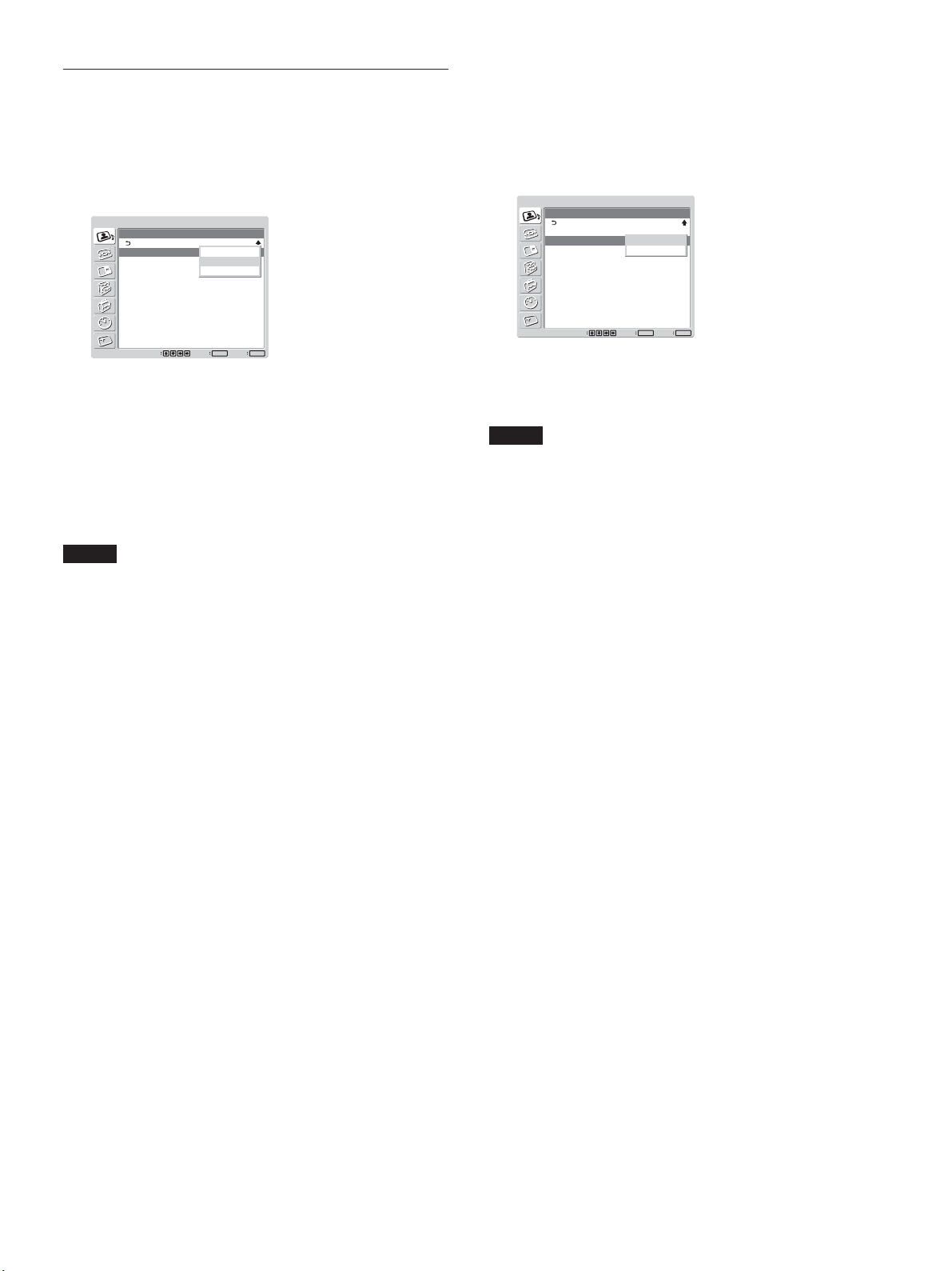
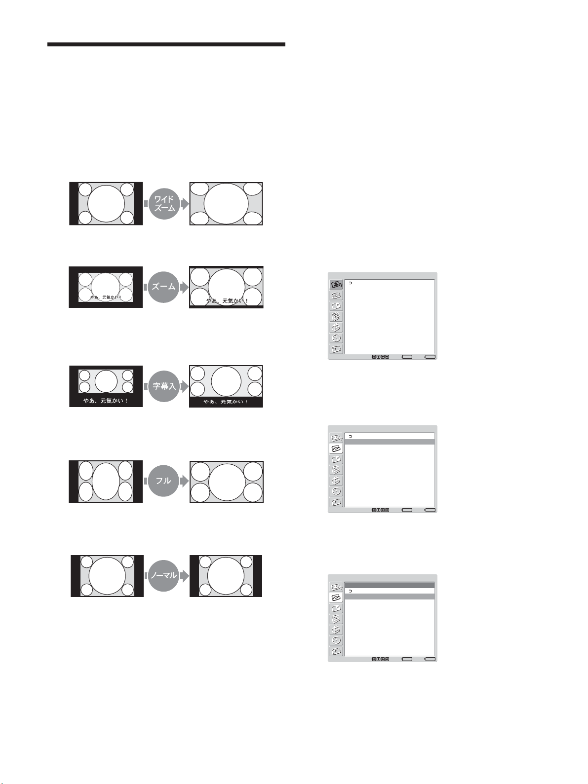
1 画面モード調整メニューから、M/mボタンで「ワイド切換」を
選び、ENTER ボタンを押す。
以下の画面が表示されます。
画面モード調整
マルチディスプレイ設定
オートワイド設定
ワイド切換:
画面調整
選択
ワイドズーム
ワイドズーム
ズーム
字幕入り
フル
ノーマル
ENTER
決定
MENU
終了
2 M/mボタンでワイドモードを 選 ぶ。
ワイドズーム:4:3 の画 像を 16:9に画面いっぱいに拡大す
る
ズーム:画面の左右に合わせていっぱいに拡大する(映像
の種類によっては上下に黒い帯が残ることがあります。)
字幕入り:画面の左右に合わせていっぱいに拡大し、字幕
部分のみを圧縮して表示する
フル:天地をそのままにして、映像の左右を画面いっぱいに
引き伸ばす
ノー マ ル : 拡大せずにそのまま表示する
8 M/mボタンで 4:3 映像のモードを 選ぶ 。
ノー マ ル : 4:3の映像をそのまま表示する
ワイドズーム:4:3 の映像を16:9に拡大して表示する
9 ENTERボタンを押す。
オートワイド設定に戻ります。
ご注意
DVI入力やRGB入力のときは、オートワイド機能が 働かないため、
オートワイドの設定もできません。
3 ENTERボタンを押す。
画面モード調整メニューに戻ります 。
ご注意
・2画面、マルチディスプレイ時にはワイド切換を設定できません。
・ワイド切換を設定すると、オートワイド機能が働きませ ん。オートワ
イド機能を使いたい場合は、「入」に再設定してください。
・映像の種類やサイズによっては、画面の上下が欠けたり、字幕
が入りきらな い 場 合 が ありま す。そのような場合は、画像のサイ
ズや位置を調整してください。
・本機を営利目的、または 公衆に視 聴させることを目 的として喫茶
店、ホテルなどに置き、ワイド切換機能等を利用して画面の圧縮
や引き伸ばし等を行 いますと、著作権法上で保護されている著
作者の権利を侵害する恐れがありますので、ご注意願います。
・本機は、各種のワイド切換機能を備えています。テレビ番組など
ソフトの 映 像 比率と異なるモードを 選択されますと、オリジナルの
映像とは見え方に差が出ます。この点にご留意の上、ワイド切換
をお選びください。
31
(JP)
Page 32

画像のサイズや位置を調整する
画像のサイズや位置を調
整する
画像の大きさや位置がディスプレイ画面に 合って いないときは、位
置を調 整したり、縦・横方向に画像のサイズを変えたりすることが
できます。
画像のサイズ、位置、ドット位相など
を調整する
MENUボタンを押してメインメニューを表示し、画面調整から調
整したい項目に応じて、「ドット位相」、「水平総ドット数 」、「水平サ
イズ 」、「水平位置」、「垂直サイズ」、「垂直位置」を調整します。
画面調整
文字や縦線のエッジにちりちりとしたノイズが多いときや、画面サ
イズ 、位置 が不適切なときに画面調整を行います。
ご注意
絵柄によっては自動調整でもノイズが消えないときがあります。こ
の場合は手動調整をしてください。
1024×768@60・1280×768@60・1360×768@60(いずれもCVT)
の3つの信号は、それぞれを自動判別できません。自動調整を実
行するたびに、それぞれの最適値が順番に適用されます。現在の
入力信号に最適な設定になるまで数回、自動調整を実行してくだ
さい。
なお、現在の設定は、リモ コン の DISPLAYボタンを押すと画面左
上に表示される入力信号情報で確認できます。
手動調整する場合
(1) M/mボタンで調整したい項目を選び、ENTER ボタンを
押す。
以下の画面が表示されます。(「ドット位 相 」を選んだ場合)
画面モード調整
画面調整
自動調整
ドット位相:
水平総ドット数:
水平サイズ:
水平位置:
垂直サイズ:
垂直位置:
標準
28
1344
30
30
30
30
1 M/mボタンで「画面調整」を選び、ENTER ボタンを押す。
以下の画面が表示されます。
画面モード調整
画面調整
自動調整
ドット位相:
水平総ドット数:
水平サイズ:
水平位置:
垂直サイズ:
垂直位置:
標準
選択
28
1344
30
30
30
30
ENTER終了MENU
決定
2 画面調整には、自動調整と手動調整の 2通りがあります。
自動調整する場合
(1) M/mボタンで「自動調整」を選び、ENTERボタンを押す。
以下の画面が表示されます。
画面モード調整
画面調整
自動調整
ドット位相:
水平総ドット数:
水平サイズ:
水平位置:
垂直サイズ:
垂直位置:
標準
選択
決定
取消
実行
28
1344
30
30
30
30
ENTER
MENU
終了
ENTER終了MENU
選択
決定
(2) M/m/</,ボタンで調整し、ENTERボタンを押す。
ドット位相
M/mボタンで「ドット位相」を選び、ENTERボタンを押し、M/m/
</,ボタンで文字や縦線が最もきれいに見える状態に調整し、
ENTERボタンを押す。
ご注意
アナログのコンピューター信号に対してのみ有効です。
水平総ドット数
M/mボタンで「水平総ドット数 」を選び、ENTERボタンを押し、M/
m/</,ボタンで文字や縦線が最もきれいに見える状態に調整
し、ENTERボタンを押す。
ご注意
アナログのコンピューター信号に対してのみ有効です。
(2) M/m ボタンで「実行」を選び、ENTERボタンを押す。
自動的に画面調整の項目すべてが調整されます。
(JP)
32
Page 33

画像のサイズや位置を調整する
水平サイズ
M/mボタンで「水平サイズ」を選び、ENTERボタンを押し、M/m/
</,ボタンで水平サイズを調整し、ENTERボタンを押す。
最小(0)〜最大(60)の範囲で設定できます。
,:水平方向にサイズが大きくなる
M
/
<:水平方向にサイズが小さくなる
m
/
水平サイズをセンター 値 に戻した いときは、自動調整をおこなって
ください。
水平位置
M/mボタンで「水平位置」を選び、ENTERボタンを押し、M/m/
</,ボタンで水平位置を調整し、ENTERボタンを押す。
最小(0)〜最大(60)の範囲で設定できます。
,:画像が右に動く
M
/
<:画像が左に動く
m
/
水平位置をセンター値に戻し た いときは、自動調整をおこなってく
ださい。
調整した画像のサイズや位置を出荷時
の状態に戻す
1 画面調整メニューから、M/mボタンで「 標 準」を選び、
ENTERボタンを押す。
以下の画面が表示されます。
画面モード調整
画面調整
自動調整
ドット位相:
水平総ドット数:
水平サイズ:
水平位置:
垂直サイズ:
垂直位置:
標準
選択
28
1344
30
30
30
取消
50
実行
ENTER終了MENU
決定
2 M/mボタンで実行を選び、ENTER ボタンを押す。
画面調整メニューの項目が工場出荷時の設定値に戻ります。
リセットを中止するには
ENTERボタンを押す前にMENUボタンを押してください。または
M/mボタンで「取消」を選び、ENTER ボタンを押してください。
垂直サイズ
M/mボタンで「垂直サイズ」を選び、ENTERボタンを押し、M/m/
</,ボタンで垂直サイズを調整し、ENTERボタンを押す。
最小(0)〜最大(60)の範囲で設定できます。
,:垂直方向にサイズが大きくなる
M
/
<:垂直方向にサイズが小さくなる
m
/
垂直サイズをセンター 値 に戻した いときは、自動調整をおこなって
ください。
垂直位置
M/mボタンで「垂直位置」を選び、ENTERボタンを押し、M/m/
</,ボタンで垂直位置を調整し、ENTERボタンを押す。
最小(0)〜最大(60)の範囲で設定できます。
,:画像が上に動く
M
/
<:画像が下に動く
m
/
垂直位置をセンター値に戻し た いときは、自動調整をおこなってく
ださい。
33
(JP)
Page 34

つの画面を表示させる
2
つの画面を表示させる
2
パソコンの映像とビデオの映像など、2種類の映像を同時に表
示させることが できます。
1 MENUボタンを押す。
メインメニューが表 示されます。
画質/音質調整
画質モード:
画質調整
音質調整
選択
スタンダード
ENTER終了MENU
決定
2 M/mボタンで「2 画面」を選び、ENTERボタンを押す。
2画面メニューが表示されます。
画面
2
画面:
2
操作入替
画サイズ
副画面位置
切
操作する画面を選んだり、画面の位置
を入れ替える
のとき
P&P
1 M/mボタンで「操作入替」を選び、ENTERボタンを押す。
以下の画面が表示されます。
画面
2
画面:
2
操作入替:
画サイズ:
副画面位置
選択 決定
P&P
左操作
右操作
画面入替
MENU
ENTER
終了
2 M/mボタンで 操 作入替のモードを 選 び、ENTERボタンを押
す。
左操作:左の画面が操作可能になる
右操作:右の画面が操作可能になる
画面入替:左右の画面が入れ替わる
のとき
PinP
MENU
ENTER
選択 決定
終了
3 M/mボタンで「2 画面」を選び、ENTERボタンを押す。
以下の画面が表示されます。
画面
2
画面:
2
操作入替
画サイズ
副画面位置
選択 決定
切
切
P&P
PinP
MENU
ENTER
終了
4 M/mボタンで 2 画面のモードを選 ぶ 。
切:2画面表示しない
:2 つの画面を左右に表示させる
P&P
:主画面の中に副画面を表示させる
PinP
5 ENTERボタンを押すと、前の画面に戻ります。
1 M/mボタンで「操作入替」を選び、ENTERボタンを押す。
以下の画面が表示されます。
画面
2
画面:
2
操作入替:
画サイズ:
副画面位置
選択 決定
PinP
主操作
副操作
画面入替
MENU
ENTER
終了
2 M/mボタンで 操 作入替のモードを 選 び、ENTERボタンを押
す。
また、操作可能画面の音声が出力されます。
主操作:主画面が操作可能になる
副操作:副画面が操作可能になる
画面入替:主画面と副画面が入れ替わる
34
(JP)
Page 35

つの画面を表示させる
2
画面の大きさを変える
のとき
P&P
1 M/mボタンで「 画 サイズ」を選び、ENTERボタンを押す。
2 拡大したい方の画面が希望の大きさになるまで </,ボタ
ンを押しながら調 整し、ENTERボタンを押す。
のとき
PinP
1 M/mボタンで「副画面サイズ」を選び、ENTERボタンを押
す。
以下の画面が表示されます。
画面
2
画面:
2
操作入替:
副画面サイズ:
副画面位置
PinP
主操作
大
小
ご注意
2画面表示できるのは、「マルチディスプレイ」の設定が「切」の
•
ときの みです。
2画面機能は、以下の入力の組み合わせで選択できます。
•
デジタル R G B アナログ RGB コンポーネント Y/C コンポジット
デジタル R G B
アナログ RGB
コンポ ーネント
Y/C
コンポジット
○ ○ ○ ○
○ ○ ○
○ ○ ○
○ ○ ○
○ ○ ○
MENU
ENTER
選択 決定
終了
2 M/mボタンで大きさを選んで、ENTERボタンを押す。
大:副画面を大きくす る
小:副画面を小さくする
副画面の位置を調整する(
PinP
のみ)
1 M/mボタンで「副画面位置」を選び、ENTERボタンを押す。
画面
2
画面:
2
操作入替:
画サイズ:
副画面位置
選択 決定
PinP
主操作
小
MENU
ENTER
終了
2 副画面を表示させたい位置をM/m/</,ボタンで選び、
ENTERボタンを押す。
35
(JP)
Page 36

マルチディスプレイの設定をする
マルチディスプレイの設
定をする
本機を複数台接続してビデオウォールなどを構成するための各種
設定を行います。
1 MENUボタンを押す。
メインメニューが表 示されます。
画質/音質調整
画質モード:
画質調整
音質調整
選択
2 M/mボタンで「画面モード調整」を選び、ENTERボタンを押
す。
画面モード調整メニューが表示されます。
画面モード調整
マルチディスプレイ設定
オートワイド設定
ワイド切換:
画面調整
スタンダード
ENTER終了MENU
決定
フル
4 M/mボタンで「マルチディスプレイ」を選び、ENTER ボタン
を押す。
以下の画面が表示されます。
画面モード調整
マルチディスプレイ設定
マルチディスプレイ:
ポジション設定
選択
切
切
2x2
3x3
4x4
ENTER終了MENU
決定
5 M/mボタンで、ビデオウォールなどの構成に合うマルチディ
スプレイのモードを選 ぶ。
切:1画面で見る。
2×2〜4×4:各構成のモードとなる。
6 ENTERボタンで、マルチディスプレイ設定メニューに戻り、
M/mボタンで「ポジション設定 /Position」を選ぶ。
画面モード調整
マルチディスプレイ設定
マルチディスプレイ:
ポジション設定
選択
3x3
ENTER
決定
MENU
終了
ENTER終了MENU
決定
選択
ご注意
「ワイド切換」が「フル」のときのみ、マルチディスプレイで拡大表
示できます。
3 M/mボタンで「マルチディスプレイ設定 」を選び、ENTERボ
タンを 押 す 。
マルチディスプレイ設定メニューが 表示されます。
画面モード調整
マルチディスプレイ設定
マルチディスプレイ:
ポジション設定
選択
切
ENTER終了MENU
決定
7 M/m/</,ボタンで、本機(設 定中のディスプレイ)のポ
ジションを 選 ぶ。
画面モード調整
マルチディスプレイ設定
マルチディスプレイ:
ポジション設定
選択
3x3
ENTER終了MENU
決定
3×3構成で右下のポジションを選ぶ場合
8 ENTERボタンを押してポジションを決 定する。
マルチディスプレイ設定に 戻ります。
ご注意
マルチディスプレイの設 定が できるのは、2画面表示が「切」のと
きのみです。
36
(JP)
Page 37

音質を調整する
音質を調整する
別売りスピーカーSS-42FWを接続しているとき、音の高音、低音、
バランスを調 整 することができます。また、サラウンドモードを 設 定
することができます 。
高音、低音、バランスなどを調整する
MENUボタンを押してメインメニューを表示し、音質調整メニュー
から調 整した い項目に応じて、「高音」、「低音」、「バランス」、「サ
ラウンド」を調整します。
高音
M/mボタンで「高音」を選び、ENTER ボタンを押し、M/m/</
,ボタンで高音を調整し、ENTERボタンを押す。
最小(−50)〜最大(50)の範囲で設定できます。
,:高音が強くなる
M
/
<:高音が弱くなる
m
/
低音
サラウンド
映像の種類に合わせて、サラウンドモードを 選ぶことができます。
1 M/mボタンで「サラウンド」を選び、ENTER ボタンを押す。
2 M/mボタンでモードを 選び 、ENTERボタンを押す。
切:サラウンド出力はしない
ホール:映画や音楽などのステレオ音声をより臨場感のある
音にする場合
シミュレ ート: 通常の放送やニュース番組のモノラル音声を
擬似的にステレオ音声にして臨場感を高める場合
調整した音質を出荷時の設定に戻す
1 音質調整メニューから、M/mボタンで「 標 準」を選び、
ENTERボタンを押す。
以下の画面が表示されます。
画質/音質調整
音質調整
高音:
低音:
バランス:
サラウンド:
標準
0
0
0
切
取消
実行
M/mボタンで「低音」を選び、ENTER ボタンを押し、M/m/</
,ボタンで低音を調整し、ENTERボタンを押す。
最小(−50)〜最大(50)の範囲で設定できます。
,:低音が強くなる
M
/
<:低音が弱くなる
m
/
バランス
M/mボタンで「バランス」を選び、ENTER ボタンを押し、M/m/
</,ボタンでバランスを調 整し、ENTER ボタンを押す。
左(50)〜右(50)の範囲で設定できます。
,:右側の音が強くなる
M
/
<:左側の音が強くなる
m
/
ENTER終了MENU
決定
選択
2 M/mボタンで「実行」を選び、ENTERボタンを押す。
音質調整メニューの項目が工場出荷時の設定値に戻ります。
リセットを中止するには
ENTERボタンを押す前に MENU ボタンを押してください。また
は、M/mボタンで「取消」を選びENTERボタンを押してください。
37
(JP)
Page 38

メニュー表示の言語を選ぶ
カラーマトリクスを調整する
/
メニュー表示の言語を選ぶ
メニュー 表 示に使う言語を、日本語、英語、ドイツ語、フランス語、
スペイン語、イタリア 語 の 6 つ の 言語の中から選ぶことが できます。
1 MENUボタンを押す。
メインメニューが表 示されます。
画質/音質調整
画質モード:
画質調整
音質調整
選択
2 M/mボタンで「初期設定/インフォメーション」を選び、
ENTERボタンを押す。
初期設定メニューが表示されます。
初期設定/インフォメーション
言語:
カラー方式:
オートシャットオフ:
自動画面調整:
インフォメーション
選択
3 M/mボタンで「言語」を選び、ENTER ボタンを押す。
以下の画面が表示されます。
初期設定/インフォメーション
言語:
カラー方式:
オートシャットオフ:
自動画面調整:
インフォメーション
選択
4 M/mボタンで表示したい言語を選び、ENTERボタンを押す。
メニュー 画面の言語が切り換わります。
日本語
English:英語
Deutsch:ドイツ語
Français:フランス語
Español:スペイン語
Italiano:イタリア語
日本語
:
スタンダード
ENTER終了MENU
決定
日本語
自動
切
入
ENTER終了MENU
決定
日本語
日本語
自動
English
切
Deutsch
入
Français
Español
DHCP
Italiano
ENTER終了MENU
決定
カラーマトリクスを調整
する
コンポ ーネント入 力 アダプターに接続した 地 上・BS・CS100度デジ
タルチューナーおよび DVD プレーヤーなどからの入 力 が、480I
(525I)、480P(525P)、1080I(1125I)、720P(750P)の各信号フォー
マットのとき、映 像が自然な色あいになるように設定できます。
1 MENUボタンを押す。
メインメニューが表 示されます。
画質/音質調整
画質モード:
画質調整
音質調整
選択
2 M/mボタンで「各種切換」を選び、ENTERボタンを押す。
各種切換メニューが表示されます。
各種切換
消費電力:
スピーカー出力:
クローズドキャプション:
ステータス表示:
カラーマトリクス:
モード:
HD
モード:
RGB
同期モード:
リモートコントロール設定
選択
3 M/mボタンで「カラーマトリクス」を選び、ENTERボタンを押
す。
以下の画面が表示されます。
各種切換
消費電力:
スピーカー出力:
クローズドキャプション:
ステータス表示:
カラーマトリクス:
モード:
HD
モード:
RGB
同期モード:
リモートコントロール設定
選択
4 M/mボタンでカラーマトリクスを選 ぶ。
Y/CB/CR
Y/PB/PR
◆設定について詳しくは、各機器に付属の取扱説明書をご覧ください。
スタンダード
ENTER終了MENU
決定
標準
切
切
切
Y/PB/PR
1080i
DTV
同期信号
ENTER
終了
ENTER終了MENU
MENU
決定
標準
切
切
切
Y/PB/PR
Y/CB/CR
1080i
Y/PB/PR
DTV
同期信号
決定
:信号フォーマットが 480Iまたは480P の場合
:信号フォーマットが 1080Iまたは720Pの場合
38
5 ENTERボタンを押すと、前の画面に戻ります。
(JP)
Page 39

電源のオン/オフを自動的に
制御する(タイマー機能)
時刻を設定して表示したり、電源を入/切する時間を自由に設定
できる電 源タイマー機 能 があります。
時刻と曜日を設定する
1 MENUボタンを押す。
メインメニューが表 示されます。
電源のオン/オフを自動的に制御する(タイマー機能)
時計を表示する
1 タイマー/時計設定メニューから、M/mボタンで「時計表示」
を選び、ENTERボタンを押す。
以下の画面が表示されます。
タイマー/時計設定
時刻設定
時計表示:
電源タイマー
選択
切
切
入
ENTER終了MENU
決定
2 M/mボタンで「タイマー/時計 設定メニュー」を選び、
ENTERボタンを押す。
タイマー/時計設定メニューが表示されます。
3 M/mボタンで「時刻設定」を選び、ENTER ボタンを押す。
以下の画面が表示され、時間の背景が黄色に変わります。
タイマー/時計設定
時刻設定
00 : 00
時刻設定:
選択
0 : 00
ENTER終了MENU
決定
月
月
4 M/mボタンで時間を設定し、ENTERボタンを押す。
時間が確定し、分の背景が黄色に変わります。
5 M/mボタンで分を設 定し、ENTERボタンを押す。
分が確定し、曜日の背景が黄色に変わります。
2 M/mボタンで「入」を選び、ENTER ボタンを押す。
メニューを消すと、画面右下に時計が表示されます。
リモコン の DISPLAYボタンを押すと、入力され ている信 号および
画質モードが表示されます。また、時計が 表示されて いる状 態で
約5秒たつと表 示は自動的に消えます。
電源タイマー機能
1 タイマー / 時 計設定メニューから、M/m ボタンで「電 源タイ
マー」を選び、ENTERボタンを押す。
以下の画面が表示されます。
タイマー/時計設定
時刻設定
時計表示:
電源タイマー
選択
切
毎日
曜日毎設定
ENTER終了MENU
決定
6 M/mボタンで曜日を設定し、ENTERボタンを押す。
曜日が確定し、前の画面に戻ります。
7 MENUボタンを押す。
通常の画面に戻ります。再度設定が必要な場合は、手順1か
ら繰り返してください。
ご注意
時刻が大幅にずれたりするときは、内蔵電池の消耗が考えられま
す。お買い上げ店またはソニーのサービス窓口に電池の交換をご
依頼ください(有料)。
2 M/mボタンで「毎日」または「曜日毎設定」を選び、ENTER
ボタンを押す。
「曜日毎設定」を選ぶと、曜日毎に時間を設定できます。
「毎日」を選ぶと、以下の画面が表示されます。
タイマー/時計設定
電源タイマー
くりかえし
選択
【電源入時間】
0 : 00
毎日
【電源切時間】
0 : 00
ENTER終了MENU
決定
39
(JP)
Page 40

電源のオン
オフを自動的に制御する(タイマー機能)/ スクリーンセーバー機能
/
3 ENTERボタンを押すと、以下の画面が表示されます。
タイマー/時計設定
電源タイマー
くりかえし
くりかえし
選択
毎日
【電源入時間】
00 : 00
0 : 00 0 : 00
【電源切時間】
00 : 00
ENTER終了MENU
決定
4 毎日同じ設定を適用するときは、M/mボタンで「くりかえし」
を に切り換え、ENTER ボタンを押す。
の
の状態でENTERボタンを押すと、1回限り適用される設 定
となります 。
タイマー/時計設定
電源タイマー
くりかえし
くりかえし
毎日
【電源入時間】
00 : 00
0 : 00 0 : 00
【電源切時間】
00 : 00
スクリーンセーバー機能
コンピ ューター の 画像のように、輝度の変化しない画像や静止画
の映像を長時間表示すると、画面に焼きつきや 残 像が生じること
があります。
これを補正したり、軽 減させるため、本機 に は スクリーン セ ー バ ー
機能が搭載されています。スクリーンセーバー機能には、画像の
色あいを反転させる(画像反転)、一定の時間がたつと画像の表
示位置を自動的に変える(自動表示位置移動)、一定時間画面全
体に白画像を表示する(オールホワイト)、背 景 の 明るさを変える
(バックグラウンド)の 4 種類があります。
また、明るさの変化の少ない画像が5分以上続いて表示された場
合、本機は自動的に明るさを徐々に制限していき画面を保護しま
す。その後、画像の明るさに変化があると、本機は明るさを徐々に
復帰させます。
ENTER終了MENU
選択
決定
5 電源入時間を設定するときは、M/mボタンで を に切り換
え、ENTERボタンを押す。
タイマー/時計設定
電源タイマー
くりかえし
くりかえし
選択
毎日
【電源入時間】
00 : 00
0 : 00 0 : 00
【電源切時間】
00 : 00
ENTER終了MENU
決定
6 M/mボタンで電源入時間を設定し、ENTERボタンを押す。
時間が確定し、分の背景が黄色で表示されます。
7 M/mボタンで分を設定し、ENTERボタンを押す。
<ボタンを押すと2 の画面に戻ります。
8 電源入時間と同様に電源切時間を設定する。
画像の色あいを反転させる
1 MENUボタンを押す。
メインメニューが表 示されます。
画質/音質調整
画質モード:
画質調整
音質調整
選択
スタンダード
ENTER終了MENU
決定
2 M/mボタンで「スクリーン セーバー」を選び、ENTERボタンを
押す。
スクリーン セー バ ーメ ニューが表示されます。
スクリーンセーバー
画像反転:
自動表示位置移動
オールホワイト:
バックグラウンド:
自動明るさ低減:
切
切
グレー
入
ENTER終了MENU
選択
決定
9 ENTERボタンを押す。
2 の画面に戻ります。
ご注意
工場出荷状態では、時刻は設定されていませんので、「--:--」と
表示します。
(JP)
40
Page 41

スクリーンセーバー機能
3 M/mボタンで「画像反転」を選び、ENTER ボタンを押す。
以下の画面が表示されます。
スクリーンセーバー
画像反転:
自動表示位置移動
オールホワイト:
バックグラウンド:
自動明るさ低減:
切
切
自動
切
入
グレー
入
ENTER終了MENU
選択
決定
4 M/mボタンで画像反転のモードを選 ぶ。
切:画像を反転しな い
自動:1日1回、設定した時刻に画像の色あいを反転する
入:画像の色あいを反転する
「自動」を選びENTERボタンを押すと、以下の画面が表示さ
れます。
スクリーンセーバー
画像反転
反転開始時間:
反転終了時間:
(1) M/mボタンで「反転開始時間」を選び、ENTERボタンを
押す。
以下の画面が表示され、時間の背景が凸状に表示されま
す。
スクリーンセーバー
画像反転
反転開始時間:
反転終了時間:
(2) M/m ボタンで時間を設定し、ENTERボタンを押す。
時間が確定し、分の背景が凸状に変わります。
(3) M/m ボタンで分を設 定し、ENTERボタンを押す。
分が確定します。<ボタンを押すと5の画面に戻ります。
(4) 反転開始時間と同様に、反転終了時間を設定する。
1日1回、反転開始時間に反転が始まり、反転終了時間
に反転表示が終了する設定になります。
ご注意
反転開始時間と反転終了時間に同じ時刻を設定すると、反転開
始時間の設定が優先され、反転終了時間になっても反転表示は
終了しません。反転表示時は反転の反転になり、通常表示になり
ます。
自動
00 : 00
00 : 00
ENTER終了MENU
選択
選択
決定
自動
00 : 00
00 : 00
00 : 00
ENTER終了MENU
決定
画像の表示位置を自動的に変える
1 スクリーン セー バ ー メニューから、M/mボタンで「自動表示位
置移動」を選び、ENTER ボタンを押す。
以下の画面が表示されます。
スクリーンセーバー
自動表示位置移動
表示位置移動:
移動量:
移動周期:
切
小
秒
30
ENTER終了MENU
決定
選択
2 M/mボタンで「表示位置移動」を選び、ENTERボタンを押
す。
以下の画面が表示されます。
スクリーンセーバー
自動表示位置移動
切
表示位置移動:
移動量:
移動周期:
切
小
入
秒
30
ENTER終了MENU
決定
選択
3 M/mボタンで表示位置移動のモードを選 ぶ 。
切:表示位置を移動しない
入:表示位置を移動する
4 ENTERボタンを押す。
1 の画面に戻ります。
5 M/mボタンで「移動量」(移動の大きさ)または「移動周期」
(移動の時間)を選び、ENTERボタンを押す。
選択できる移動量、移動周期は以下のとおりです。
移動量:小、中、大
移動周期:10秒、30 秒、1分、5分
以下の画面が表示されます。(下図は「移動量」を選んだ場
合)
スクリーンセーバー
自動表示位置移動
表示位置移動:
移動量:
移動周期:
切
小
小
秒
中
30
大
ENTER終了MENU
決定
選択
41
(JP)
Page 42

スクリーンセーバー機能
6 M/mボタンで移動量または移動周期を設定し、ENTERボタ
ンを押 す。
画像反転と自動表示位置移動の両方を入にすると
画像が反転中に一定時間がたつと、反転した画像が表示位置を
変えて表示されます。
画面全体に白画像を出す
画面の焼き付きや残像を低減させるために、画面全体に白画面を
約30分間表示します。
1 スクリーン セー バ ー メニューから、M/mボタンで「 オールホワ
イト」を選び、ENTERボタンを押す。
以下の画面が表示されます。
スクリーンセーバー
画像反転:
自動表示位置移動
オールホワイト:
バックグラウンド:
自動明るさ低減:
切
切
切
グレー
入
入
ENTER終了MENU
決定
選択
2 M/mボタンで「入」を選び、ENTERボタンを押す。
2 M/mボタンで 背 景の明るさのモードを選 び、ENTERボタンを
押す。
グレー:明るく設定する
ダークグレー:中間の明るさに設定する
ブラック:暗く設定する
背景と映像の色(明るさ)が近いほど、焼き付きや残像は軽
減されます。
画面を徐々に暗くする
静止画の表示が5 分以上続くと、徐 々に輝 度を落として焼き付き
を軽減します。
1 スクリーン セーバーメニューから、M/mボタンで「自動明るさ
低減」を選び、ENTER ボタンを押す。
以下の画面が表示されます。
スクリーンセーバー
画像反転:
自動表示位置移動
オールホワイト:
バックグラウンド:
自動明るさ低減:
切
切
グレー
入
切
入
ENTER終了MENU
選択
決定
「オールホワイト」での白画面表示を途中でやめるには
手順2 で「切」を選びます。
背景の明るさを変える
4:3映像をワイドモードのノー マルで表示したときに、画面左右の
映像のない部分と映像のある部分との間 で生じる焼き付きや残 像
を軽減させるために、映像のない部分の明るさを明るく変えること
ができます。
1 スクリーン セー バ ーメニューから、M/mボタンで「バックグラウ
ンド」を選び、ENTERボタンを押す。
以下の画面が表示されます。
スクリーンセーバー
画像反転:
自動表示位置移動
オールホワイト:
バックグラウンド:
自動明るさ低減:
切
切
グレー
グレー
入
ダークグレー
ブラック
ENTER終了MENU
決定
選択
2 M/mボタンで「入」を選び、ENTER ボタンを押す。
「自動明るさ低減」で画面が暗くならない ように す るには
手順2 で「切」を選びます。
42
(JP)
Page 43

アドレスおよび通信速
IP
アドレスおよび通信速度を設定する
IP
4 M/mボタンで「DHCP」を選び、ENTER ボタンを押す。
以下の画面が表示されます。
度を設定する
本機のCOMMUNICATIONスロットに オプションアダプター
BKMFW32(NetworkManagementAdaptor)を装着した場合
に、ネットワーク経由で本機を制御するためのIPアドレスお よ び 通
信速度を設定します。
ご注意
IPアドレスおよび通信速度の設定は、「Execute」を選び、ENTER
ボタンを押 すと設定 が完了します。
設定値が正しく完了しない 場 合は 、エラーコードが出ます の で、設
定値を確認して設定しなおし てください。
アドレスを自動取得する(
IP
1 MENUボタンを押す。
メインメニューが表 示されます。
画質/音質調整
画質モード:
画質調整
音質調整
スタンダード
DHCP
)
初期設定/インフォメーション
IP Address Setup
DHCP
Manual
Cancel
Execute
ENTER終了MENU
決定
選択
5 M/mボタンで「Execute」を選び、ENTERボタンを押す。
IPアドレ スが自動取得されます。
アドレスをマニュアルで設定する
IP
(
Manual
)
1 「IPアドレ スを 自動取得する」の手順4で「Manual」を選び、
ENTERボタンを押す。
以下の画面が表示されます。
初期設定/インフォメーション
IP Address Setup
IP Address:
Subnet Mask:
Gateway Address:
Primay DNS:
Secondary DNS:
Execute
選択
Manual
000 . 000 . 000 . 000
000 . 000 . 000 . 000
000 . 000 . 000 . 000
000 . 000 . 000 . 000
000 . 000 . 000 . 000
ENTER終了MENU
決定
ENTER終了MENU
選択
決定
2 M/mボタンで「初期設定/インフォメーション」を選び、
ENTERボタンを押す。
初期設定/インフォメーションメニューが表示されます。
初期設定/インフォメーション
言語:
カラー方式:
オートシャットオフ:
自動画面調整:
インフォメーション
IP Address Setup
Speed Setup
選択
日本語
自動
切
入
ENTER終了MENU
決定
3 M/mボタンで「IPアドレス設定」を選び、ENTERボタンを押
す。
以下の画面が表示されます。
初期設定/インフォメーション
IP Address Setup
DHCP
Manual
ENTER終了MENU
選択
決定
2 M/mボタンで手動入力する項目を選び、ENTERボタンを押
す。
初期設定/インフォメーション
IP Address Setup
IP Address:
Subnet Mask:
Gateway Address:
Primay DNS:
Secondary DNS:
Execute
選択
Manual
000 . 000 . 000 . 000
000 . 000 . 000 . 000
000 . 000 . 000 . 000
000 . 000 . 000 . 000
000 . 000 . 000 . 000
000 . 000 . 000 . 000
ENTER終了MENU
決定
3 M/mボタンまたはリモコンの数字ボタン で 3 桁 の 数値(0〜
255)を入力して、ENTERボタンまたは ,ボタンを押す。
右の枠にカーソルが移動します。
初期設定/インフォメーション
IP Address Setup
IP Address:
Subnet Mask:
Gateway Address:
Primay DNS:
Secondary DNS:
Execute
選択
Manual
000 . 000 . 000 . 000
000 . 000 . 000 . 000
000 . 000 . 000 . 000
000 . 000 . 000 . 000
000 . 000 . 000 . 000
000 . 000 . 000 . 000
ENTER終了MENU
決定
4 4つの枠にそれぞれ入力して、ENTERボタンを押す。
以下の画面が表示されます。
初期設定/インフォメーション
IP Address Setup
IP Address:
Subnet Mask:
Gateway Address:
Primay DNS:
Secondary DNS:
Execute
選択
Manual
123 . 123 . 012 . 034
000 . 000 . 000 . 000
000 . 000 . 000 . 000
000 . 000 . 000 . 000
000 . 000 . 000 . 000
ENTER終了MENU
決定
43
(JP)
Page 44

アドレスおよび通信速度を設定する
IP
自己診断機能
/
特定のディスプレイをリモコンで操作する
/
5 M/mボタンで次に設定したい項目を選び、各項目に対して
同じ操 作をくり返し、ENTERボタンを押す。
自己診断機能
6 必要項目の入力が終わったら、「Execute」を選び、ENTER
ボタンを押す。
IPアドレスが手動で設定されました。
ご注意
エラーコードは 、以下のようにIPアドレスが 正しく設定完了しない
ときに 表 示されます。
Error 1
Error 2
Error 3
Error 4
Error 5
Error 6
Error 7
通信速度を設定する
本体とBKM-FW32 の間の通信エラー
IPaddressが他で使われている
IPaddressの設定不備
Gatewayaddressの設定不備
PrimaryDNSの設定不備
SecondaryDNSの設定不備
Subnetmaskの設定不備
(Speed Setup)
1 初期設定/インフォメーションメニューから、M/m ボタンで
「SpeedSetup」を選び、ENTER ボタンを押す。
初期設定/インフォメーション
Speed Setup
Speed:
Execute
Auto Detect
本機には自己診断機能が搭載されています。これは 本 機が 正しく
動作していないときに、POWER/STANDBYインジ ケーターの 点
滅によりお知らせする機能です。点滅状態によって本機の状態が
分かるようになっています。
POWER/STANDBYインジ ケーターが点滅したら、点滅状態を確認
して、お買い上げ店またはソニーサービス窓口にご相談ください。
1 POWER/STANDBYインジ ケーターの 点滅状態を確認する。
画面が消えずにインジケーターが 点滅し て いる場 合と、画 面
が消えてインジケーターが 3 秒 おきに点滅する場合がありま
す。画面が消えてインジケーターが 3 秒おきに 点 滅し て いる場
合には、点滅回数を数えてください 。たとえば、2回点滅→ 3
秒あき→ 2 回点滅…この場合の点滅回数は2回です。
2 本機の電源コードを抜く。
お買い上げ店またはソニーサービス窓口にインジケーターの
点滅回数をお知らせください。
特定のディスプレイをリモ
ン
で操作する
コ
ENTER終了MENU
決定
選択
2 ENTERボタンを押して、通信速度をM/mボタンで選択し
て、ENTERボタンを押す。
「AutoDetect」を選択すると、ネットワーク環 境 に 対応した通
信速度が自動的に設定できます。
初期設定/インフォメーション
Speed Setup
Speed:
Execute
Auto Detect
Auto Detect
10Mbps/Half Dup
10Mbps/Full Dup
100Mbps/Half Dup
100Mbps/Full Dup
ENTER終了MENU
決定
選択
3 「Execute」を選んでENTERボタンを押す。
通信速度が設定されます。
複数のディスプレイを使用しているとき、インデックス番号を指定し
て、特定のディスプレイの みを操作することができます。
1 リモ コンの IDMODEON ボタンを押す。
インデックス番号が、画面左下のメニューに黒い文字で表示
されます。(インデックス番号は、1から255の範囲で、あらか
じめ各ディスプレイに設定されています。)
◆インデックス番号を変更したいときは、「インデックス番号を変更す
るには 」(44(JP)ペ ージ )をご覧ください。
SETON OFF
インデックス番号
インデックス番号
117
. . .
44
(JP)
Page 45

特定のディスプレイをリモコンで操作する
2 リモ コンの 数 字ボタンで、操作したいディスプレイのインデック
ス番号を入力 する。
すべてのディスプレイのインデックス番 号の右に、入力した数
字が表示されます。
入力した数字
213
546
879
0
SETON OFF
インデックス番号
117
117
3 IDMODESETボタンを押す。
選択したディスプレイの文 字が緑 色に変わり、その他のディス
プレイの 文 字は赤色に変わります。
SETON OFF
これで特定のディスプレイ(文字が緑色に変わったディスプレ
イ)のみを操作できます(電源ON/STANDBYは他のディス
プレイにも有効です)。
2 M/mボタンで「各種切換」を選び、ENTERボタンを押す。
以下の画面が表示されます。
各種切換
消費電力:
スピーカー出力:
クローズドキャプション:
ステータス表示:
カラーマトリクス:
モード:
HD
モード:
RGB
同期モード:
リモートコントロール設定
選択
標準
切
切
切
Y/PB/PR
1080i
DTV
同期信号
ENTER終了MENU
決定
3 M/mボタンで「リモ ートコントロール設定」を選び、ENTERボ
タンを 押 す 。
リモ ートコントロール設定メニューが表示されます。
各種切換
リモートコントロール設定
インデックス番号:
コントロールモード:
選択
1
本体+リモコン
ENTER終了MENU
決定
4 M/mボタンでインデックス番号を選び、ENTERボタンを押
す。
リモ ートコントロール設定メニューに 戻ります。
4 設定変更等の操作が終了したら、IDMODEOFFボタンを押
す。
ディスプレイは通常の画面に戻ります。
SETON OFF
インデックス番号を変更するには
必要に応じてインデックス番号を変更できます。変更する場合は、
ディスプレイ本体 のコントロールボタン部のボタンをお使いください。
また、リモコン で の 設定はできません。
1 MENUボタンを押す。
メインメニューが表 示されます。
画質/音質調整
画質モード:
画質調整
音質調整
スタンダード
ENTER終了MENU
選択
決定
(JP)
45
Page 46

電源接続時のご注意
それぞれの地域に合った電源コードをお使いください。
アメリカ合衆国、カナダ ヨーロッパ諸国
プラグ型名 VM0233 COX-07 636 —
イギリス、アイルランド、オー
ストラリア、ニュージーランド
1)
日本
VM1296
コネクタ型名 VM0089 COX-02 VM0310B VM0303B VM1313
コード型名 SVT H05VV-F CEE (13) 53rd (O.C) HVCTF
定格電圧・電流 10A/125V 10A/250V 10A/250V 10A/125V
安全規格 UL/CSA VDE VDE 電安法
............................................................................................................................................................................................................................................................
1) プラグに関しては各国・地域規制に適合し、使用に適した定格のものを使用してください。
(JP)
46
Page 47

仕様
映像処理系
プリセット信 号 入 力プリセット信 号(26(JP)ページ)参照
サンプリング周波数 13.5MHz〜 140MHz
パネル方式 プラズマディスプレイパネル
解像度 852ドット(水平)×480ライン(垂直)
FWD-42PV1/42PV1A:
ピクセルピッチ 1.08(水平)×1.08(垂直)mm
有効表示寸法 920(水平)×518(垂直)mm
画面サイズ 42(V)型(対角 1056mm)
FWD-42PV1P:
ピクセルピッチ 1.08(水平)×1.08(垂直)mm
有効表示寸法 518(水平)×920(垂直)mm
画面サイズ 42(V)型(対角 1056mm)
仕様
VIDEOOUT
BNC型(×1)ル ー プスル ー
SVIDEOIN ミニDIN4ピン(× 1)
Y(輝度):1Vp-p±2dB同期負、
75Ω終端
C( クロ マ ):バースト 0.286Vp-p
±2dB(NTSC)、75Ω終端
バースト0.3Vp-p±2dB(PAL)、
75Ω終端
SVIDEOOUT ミニDIN4ピン(× 1)ループスルー
AUDIOIN ピンジャック(× 2)
500mVrms、ハイインピ ーダンス
入出力
INPUT1
DVI DVI(DVI規格1.0 準拠)
AUDIO ステレオミニジャック(×1)
500mVrms、ハイインピ ーダンス
INPUT2
RGB/COMPONENT
D-sub15ピン(メス)(× 1)
(「ピン配列」参照)
AUDIO ステレオミニジャック(×1)
500mVrms、ハイインピ ーダンス
CONTROL S IN/OUT
AUDIO OUT
REMOTE(RS-232C
SPEAKER
ミニジャック(× 2)
ピンジャック(×2)
500mVrms、ハイインピ ーダンス
)
D-sub9ピン(× 1)
7W+ 7W(6Ω)
適合負荷インピ ーダンス6 〜 16Ω
ビデオ/Sビデオ入出力アダプター
BKM-FW10
VIDEO(NTSC、PAL、SECAM、NTSC4.43
PAL60、PAL-M、PAL-N
VIDEOIN BNC型(×1)
コンポジットビデオ1Vp-p±2dB同期負、
)
75Ω自動終端
、
47
(JP)
Page 48

仕様
その他
電源 AC100V〜240V、50/60Hz、
FWD-42PV1/42PV1P/42PV1A:
3.5A(最大)
消費電力 FWD-42PV1/42PV1P/42PV1A:
260W
ACOUT 最大定格電流 0.25Aあるいは最大消費電
力30Wまで
動作条件 温度:0〜+ 35℃
湿度:20〜 90%(結露のないこと)
気圧:
FWD-42PV1/42PV1P:800〜 1100hPa
保存・輸送条件 温度:− 10 〜+ 40℃
湿度:20〜 90%(結露のないこと)
気圧:
FWD-42PV1/42PV1P:700〜 1100hPa
外形寸法 FWD-42PV1/42PV1A:
1033× 631× 121mm
FWD-42PV1P:
631× 1033× 121mm
(幅/高さ/奥行き、最大突起部
含まず)
質量 FWD-42PV1/42PV1P/42PV1A:約29kg
付属品 電源コード(1)
ACプラグホルダー(2)
デジタル RGB(DVI-D)信号ケーブル(シ
ングルリンク)(1)
コンポ ー ネントビデオケーブル(D-sub15
ピン -RCA×3)(1)
BNC-RCA変換アダプター(1)
ケーブルホルダー(4)
変換プラグアダプター(1)
リモコン RM-980(1)
単4形乾電池(2)
取扱説明書(1)
保証書(ソニー業務用製品ご相談窓口の
ご案内)(1)
ピン配列
RGB/COMPONENT
ピン
No.
1赤映像信号またはR-Y 信号またはPR 信号
2緑映像信号またはY 信号またはSyncOnGreen信号
3青映像信号またはB-Y 信号またはPB 信号
4接地(GND)
5接地(GND)
6 赤接地(GND)
7 緑接地(GND)
8 青接地(GND)
9 未使用
10 接地(GND)
11 接地(GND)
12 SDA
13 水平同期信号または複合同期信号
14 垂直同期信号
15 SCL
信 号
端子(
D-sub 15
ピン)
別売りアクセサリー
スタンドSU-42FW
スピ ーカーSS-SP42FW
機能拡張用オプションアダプターBKM-
FWシリーズ
本機の仕様および外観は、改良のため予告なく変更することがあ
ります が 、ご了承ください。
(JP)
48
Page 49

保証書とアフターサービス
保証書
この製品には保証書が添付されていますので、お買い上げの際
•
お受け取りください。
所定事項の記入および記載内容をお確かめのうえ、大切に保存
•
してください。
アフターサービス
調子が悪いときはまずチェックを
この説明書をもう一 度ご 覧に なってお調べください。
それでも具合の悪いときはサービスへ
お買い上げ店、または添付の「サービス窓口・ご相談窓口のご案
内」にあるお近くのソニーサービス窓口にご相談ください。
保証書とアフターサービス
保証期間中の修理は
保証書の記載内容に基づいて修理させていただきます。詳しくは
保証書をご覧ください。
保証期間経過後の修理は
修理によって機能が維持できる場合は、ご要望により有料修理を
させ て い ただきます 。
49
(JP)
Page 50

WARNING
Owner’s Record
The model and serial numbers are located on the rear.
Record the model and serial numbers in the spaces
provided below. Refer to these numbers whenever you call
upon your Sony dealer regarding this product.
Model No. Serial No.
To reduce the risk of fire or electric
shock, do not expose this apparatus to
rain or moisture.
To avoid electrical shock, do not open the
cabinet. Refer servicing to qualified
personnel only.
On transportation
When you carry the display unit, hold the unit itself, not the
speakers. If you fail to do so, the speakers may come out of
the unit and the unit may fall. This can cause injury.
For customers in the U.S.A.
If you have any questions about this product, you may
call; Sony Customer Information Services Center
1-800-222-7669 or http://www.sony.com/
Declaration of Conformity
Trade Name: SONY
Model: FWD-42PV1/42PV1P/42PV1A
Responsible Party: Sony Electronics Inc.
Address: 16530 Via Esprillo,
San Diego, CA 92127 U.S.A.
Telephone Number: 858-942-2230
This device complies with Part 15 of the FCC Rules.
Operation is subject to the following two conditions: (1) This
device may not cause harmful interference, and (2) this
device must accept any interference received, including
interference that may cause undesired operation.
This equipment has been tested and found to comply with
the limits for a Class B digital device, pursuant to Part 15 of
the FCC Rules. These limits are designed to provide
reasonable protection against harmful interference in a
residential installation. This equipment generates, uses, and
can radiate radio frequency energy and, if not installed and
used in accordance with the instructions, may cause harmful
interference to radio communications. However, there is no
guarantee that interference will not occur in a particular
installation. If this equipment does cause harmful
interference to radio or television reception, which can be
determined by turning the equipment off and on, the user is
encouraged to try to correct the interference by one or more
of the following measures:
• Reorient or relocate the receiving antenna.
• Increase the separation between the equipment and
receiver.
• Connect the equipment into an outlet on a circuit different
from that to which the receiver is connected.
• Consult the dealer or an experienced radio/TV technician
for help.
You are cautioned that any changes or modifications not
expressly approved in this manual could void your authority
to operate this equipment.
For customers in Canada
This class B digital apparatus complies with Canadian
ICES-003.
Voor de klanten in Nederland
• Dit apparaat bevat een vast ingebouwde batterij die niet
vervangen hoeft te worden tijdens de levensduur van het
apparaat.
• Raadpleeg uw leverancier indien de batterij toch
vervangen moet worden. De batterij mag alleen
vervangen worden door vakbekwaam servicepersoneel.
• Gooi de batterij niet weg maar lever deze in als klein
chemisch afval (KCA).
• Lever het apparaat aan het einde van de
levensduur in voor recycling, de batterij zal
dan op correcte wijze verwerkt worden.
The socket-outlet should be installed near the equipment
and be easily accessible.
NL
2 (GB)
CAUTION
RISK OF EXPLOSION IF BATTERY IS REPLACED BY
AN INCORRECT TYPE. DISPOSE OF USED
BATTERIES ACCORDING TO THE LOCAL RULES.
Page 51

Table of Contents
Precautions ............................................................... 5 (GB)
Location and Function of Parts and Controls ....... 7 (GB)
Front / Rear / Left side / Right side / Bottom .......... 7 (GB)
Indicator Section ...................................................... 8 (GB)
Control Button Section (Top) .................................. 8 (GB)
Connector Panel (Bottom) ....................................... 9 (GB)
Connector Panel (Left side) ................................... 10 (GB)
Remote Commander RM-980 ................................ 12 (GB)
Caution .................................................................... 14 (GB)
Connections ............................................................ 15 (GB)
Connecting the Speakers ........................................ 15 (GB)
Connecting the AC Power Cord ............................ 15 (GB)
Cable management ................................................. 16 (GB)
Using On-screen Menus ........................................ 17 (GB)
Operating Through Menus ..................................... 17 (GB)
Menu Guide ........................................................... 17 (GB)
Watching the Picture .............................................. 23 (GB)
Switching the Input Signal ..................................... 23 (GB)
Input Signal, Picture Mode and Display Status
Information ....................................................... 24 (GB)
Selecting Image Quality ......................................... 26 (GB)
Adjusting the Picture ............................................. 26 (GB)
Adjusting the Contrast, Brightness, Chroma, and
Phase, etc. ......................................................... 26 (GB)
Restoring the Adjust Picture Menu Items to Their
Original Settings ............................................... 28 (GB)
Picture Enlargement ............................................... 29 (GB)
Setting Auto Wide ................................................. 29 (GB)
Setting the Aspect .................................................. 30 (GB)
Resizing and Positioning the Picture ................... 31 (GB)
Adjusting the Size, Position, or the Pixels of
the Picture ......................................................... 31 (GB)
GB
English
Restoring the adjusted Size or Position to Their
Original Settings ............................................... 32 (GB)
Viewing two pictures at the same time ................. 33 (GB)
Activating a picture or swapping the positions of
two pictures ....................................................... 33 (GB)
3 (GB)
Page 52

Zooming in on a picture ......................................... 34 (GB)
Adjusting the position of the inset picture
(For PinP only) ................................................. 34 (GB)
Setting up the Multi Display .................................. 35 (GB)
Adjusting the Sound Quality ................................. 36 (GB)
Adjusting the Treble, Bass, and Balance, etc. ....... 36 (GB)
Restoring the Adjust Sound Menu Items to Their
Original Settings ............................................... 36 (GB)
Selecting the On-screen Language ...................... 37 (GB)
Adjusting Color Matrix ........................................... 37 (GB)
Controlling Power On/Off Automatically (Timer
Function)............................................................. 38 (GB)
Adjusting the time and the day .............................. 38 (GB)
Displaying the time ................................................ 38 (GB)
On/Off Timer Function .......................................... 39 (GB)
SCREEN SAVER Function ..................................... 40 (GB)
Reversing the Color Tones of the Image ............... 40 (GB)
Changing the Image Position Automatically ......... 41 (GB)
Turning the screen all white................................... 41 (GB)
Adjusting the brightness of background of
picture ............................................................... 41 (GB)
Lowers the brightness level gradually ................... 42 (GB)
Setting an IP address and communication
speed................................................................... 42 (GB)
Obtaining an IP address automatically (DHCP) .... 42 (GB)
Setting an IP address manually (Manual) .............. 42 (GB)
Setting a communication speed ............................. 43 (GB)
Self-diagnosis Function ......................................... 43 (GB)
Operating a Specific Display With the Remote
Commander ........................................................ 44 (GB)
Specifications ......................................................... 45 (GB)
4 (GB)
Page 53

Precautions
On safety
•A nameplate indicating operating voltage, power
consumption, etc. is located on the rear of the unit.
• Should any solid object or liquid fall into the cabinet,
unplug the unit and have it checked by qualified
personnel before operating it any further.
•Unplug the unit from the wall outlet if it is not to be
used for several days or more.
• To disconnect the AC power cord, pull it out by
grasping the plug. Never pull the cord itself.
•When you install the unit on the floor, be sure to use
the optional stand.
On installation
•Allow adequate air circulation to prevent internal
heat build-up. Do not place the unit on surfaces
(rugs, blankets, etc.) or near materials (curtains,
draperies) that may block the ventilation holes.
•Do not install the unit in a location near heat sources
such as radiators or air ducts, or in a place subject to
direct sunlight, excessive dust, mechanical vibration
or shock.
•When you install multiple equipment with the unit,
the following problems, such as malfunction of the
Remote Commander, noisy picture, noisy sound,
may occur depending on the position of the unit and
other equipment.
On the PDP (Plasma Display Panel)
•You may see some bright spots of red, blue or green
remain, or dark spots appear on the screen. These do
not indicate malfunction. Although the plasma
display panel is manufactured with extremely high
precision technology, it can generate a few dark or
bright pixels. Dark spots on the edge of the screen, or
striped color and brightness irregularities do not
indicate malfunction.
•Do not display the same still image on the screen for
a long time. Otherwise, an afterimage or ghost may
appear on a part of the panel. Use the screen saver
function to equalize use of the screen display.
•Because of the way it is made, when this plasma
display panel is used in places with low air pressure,
such as at high altitudes, a buzzing or humming
noise may emanate from the unit.
Precautions
• If you continue to display the same image on the
screen for a long period of time, part of that image
may burn into the screen and leave a ghosting image
behind. To avoid this, please use the screen saver
function provided to equalize use over the entire
screen. If ghosting occurs, use the screen saver
function, or use some kind of video or imaging
software to provide constant movement on the
screen. If light ghosting (image burn-in) occurs,it
may become less conspicuous, but once burn-in
occurs, it will never completely disappear.
• To protect the plasma display, this unit will not
accept commands from the Remote Commander or
from the function buttons on the unit for a certain
period of time after the unit has been switched ON/
STANDBY. After one of these operations, wait
about 5 seconds before entering a command.
On cleaning
•Be sure to unplug the power cord before cleaning the
display.
•Gently wipe off stains using a dry, soft cloth. Wipe
off grimy stains using a cloth slightly moistened with
a mild detergent, then wipe the area again using a
dry, soft cloth.
•Never use rubbing alcohol, benzine or thinner for
cleaning. They may damage the finish of the cabinet
or can remove the markings on it.
Notes on handling and cleaning the display
panel
The display panel’s special surface finish should be
treated with care when cleaning or handling the TV.
When cleaning it, use a soft cleaning cloth to avoid
touching the panel directly.
On repacking
Do not throw away the carton and packing materials.
They make an ideal container in which to transport the
unit. When shipping the unit, repack it as illustrated
on the carton.
If you have any questions on this unit, contact your
authorized Sony dealers.
5 (GB)
Page 54

Precautions
Disposal of Old Electrical & Electronic Equipment
(Applicable in the European Union and other
European countries with separate collection systems)
This symbol on the product or on its
packaging indicates that this product
shall not be treated as household
waste. Instead it shall be handed over
to the applicable collection point for
the recycling of electrical and
electronic equipment. By ensuring
this product is disposed of correctly,
you will help prevent potential
negative consequences for the environment and
human health, which could otherwise be caused by
inappropriate waste handling of this product. The
recycling of materials will help to conserve natural
resources. For more detailed information about
recycling of this product, please contact your local
city office, your household waste disposal service or
the shop where you purchased the product.
Warning on power connection
Use the proper power cord for your local power supply.
United States, Continental United Kingdom, Ireland, Japan
Canada Europe Australia, New Zealand
Plug type VM0233 COX-07 636 —
Female end VM0089 COX-02 VM0310B VM0303B VM1313
Cord type SVT H05VV-F CEE (13) 53rd (O.C) HVCTF
Minimum cord set rating 10A/125V 10A/250V 10A/250V 10A/125V
Safety approval UL/CSA VDE VDE DENAN-HO
a) Note: Use an appropriate rating plug which complies with local regulations.
a)
VM1296
6 (GB)
Page 55

Location and Function of Parts and Controls
2 3
5
7
76
Location and Function
of Parts and Controls
Front / Rear / Left side / Right side /
Bottom
Front
1
Rear
Right side
100-240V~ 50-60Hz
Maximum 0.25A
4
5
Bottom
SPEAKER RAC OUT FUSE
T500mA H
250V
1 Indicator section
For details on the Indicator section, see “Indicator
Section” on page 8 (GB).
2 Control button section
For details on the control button section, see “Control
Button Section (Top)” on page 8 (GB).
4 756
Left side
7
5
3 Stand installation hooks
Use these hooks to install the stand (not supplied).
4 AC OUT socket (three brade type)
You can connect a device consuming small power to
this socket and supply power when setting up an
audio/visual system (the maximum current rating:
0.25 A; the maximum power consumption: 30 W). For
more details, consult your Sony dealer.
Note
Be sure not to connect the device of which current
rating or power consumption exceeds its rating.
5 SPEAKER Socket
Connects the speakers (not supplied) to this socket to
output the audio matching the signal displayed on the
screen.
6 - AC IN socket
Connect the supplied AC power cord to this socket
and to a wall outlet. Once you connect the AC power
cord, the POWER/STANDBY indicator lights up in
red and the display goes into the standby mode.
For more details on the power cord, see “Connecting the
AC Power Cord” on page 15 (GB).
7 Connector panel
For details on the connector panel, see “Connector Panel
(Bottom)” on page 9 (GB) and “Connector Panel (Left
side)” on page 10 (GB).
7 (GB)
Page 56

Location and Function of Parts and Controls
1
2
3
4
5
6
Indicator Section
1 2
1 Remote control detector
Receives the signals from the Remote Commander.
2 POWER/STANDBY indicator
Lights up in green when the display unit is powered
on. Lights up in red in the standby mode. Lights up in
orange when the display enters the power saving
mode while a signal is input from a computer.
When the POWER/STANDBY indicator blinks, see “Selfdiagnosis Function” on page 43 (GB).
Control Button Section (Top)
1 INPUT button
Press to select a signal to be input from the INPUT or
OPTION1 connector.
The signal to be input switches as follows each time
you press the INPUT1 button.
INPUT1 INPUT2 OPTION1
When an option adaptor is not installed in the
OPTION1 slot, OPTION1 will be skipped.
2 MENU button
Press to show menus. Press again to hide them.
34 m/M (cursor/volume) button
Press to move the cursor (yellow), set a value, or
control speaker volume.
5 ENTER button
Press to set your choice.
6 1POWER switch
Press to power on the display unit. Press again to
return to the standby mode.
Note
To protect the panel, a certain amount of time is
required to turn the unit ON/STANDBY. Wait about 5
seconds after one of these operations before executing
the next operation.
8 (GB)
Page 57

Connector Panel (Bottom)
1 52 3 4
Location and Function of Parts and Controls
AC IN REMOTE
OUTIN L
CONTROL S
1 REMOTE (RS-232C) connector (D-sub 9-pin)
This connector allows remote control of the display
using the RS-232C protocol. For details, contact your
authorized Sony dealers.
2 CONTROL S IN/OUT (Control S Signal Input/
Output) Connector (Minijack)
You can control multiple devices with a single remote
commander when connected to the CONTROL S
connector of a video device or other display. Connect the
CONTROL S OUT connector on this display to the
CONTROL S IN connector of the other device, and
connect the CONTROL S IN connector on this display
to the CONTROL S OUT connector of the other device.
3 AUDIO OUT L/R (Pinjack)
Outputs an audio of the signal currently indicated on
the screen.
Outputs an audio signal corresponding to the Active
Picture while in the P&P or PinP mode.
AUDIO AUDIO
R
AUDIO OUT
DVI-HDCP
INPUT 1 INPUT 2
RGB/COMPONENT
4 INPUT1 (DIGITAL RGB IN) connectors
DVI : Connects to the digital RGB signal output of
video devices. Supports HDCP copy protection.
AUDIO (Stereo minijack) : Inputs an audio signal.
Connects to the audio output of video devices.
5 INPUT2 (ANALOG RGB/COMPONENT IN)
connectors
RGB/COMPONENT (D-sub 15-pin) : Connects to
the analog RGB signal or component (YUV)
signal output of a piece of video equipment.
AUDIO (Stereo minijack) : Inputs an audio signal.
Connects to the audio output of a piece of video
equipment.
9 (GB)
Page 58

Location and Function of Parts and Controls
Connector Panel (Left side)
COMMUNICATION
6
Slot
COMMUNICATIONOPTION 1 (VIDEO/COM)SPEAKER L
7 8
OPTION1
(VIDEO/COM)
Slot
6 COMMUNICATION slot
This slot supports commucation function.
A blank panel is attached to this slot for the factory
setting.
When you install the optional adaptor BKM-FW32
(Network Management Adaptor) in this slot, you can
control the display unit via the network.
7 VIDEO connectors
S VIDEO IN (Mini DIN 4-pin) : Connects to the Y/
C signal output of a piece of video equipment.
S VIDEO OUT (Mini DIN 4-pin) : Connects to the
Y/C signal input of a piece of video equipment.
VIDEO IN (BNC) : Connects to the video signal
output of a piece of video equipment.
VIDEO OUT (BNC) : Connects to the video signal
input of a piece of video equipment.
AUDIO IN L/R (Pinjack) : Inputs an audio signal.
Connects to the audio output of a piece of video
equipment.
8 OPTION1 (VIDEO/COM) slot
This slot supports video signals and communication
function.
10 (GB)
Page 59

Location and Function of Parts and Controls
Optional adaptors (Not supplied)
The connectors marked with 7 on the connector
panel are slot-in types and can be fitted with any of
the optional adaptors in the display; BKM-FW10,
BKM-FW11 or BKM-FW12.
(A BKM-FW10 is the same as the connectors 7.)
For details on installation, consult your Sony dealers.
COMPONENT/RGB Input Adaptor BKM-FW11
(Not supplied)
1
R/CR/R PB/CB/B Y/G
2
3
VD HD P
COMPONENT/RGB INPUT ADAPTOR
AUDIO
RGB/COMPONENT ACTIVE THROUGH
ADAPTOR BKM-FW12 (Not supplied)
AUDI O
IN
OUT
RGB/COMPONENT THROUGH
IN
1
2
3
1 RGB/COMPONENT IN (D-sub 15-pin) :
Connects to the component signal output or analog
RGB signal output of a piece of video equipment or a
computer.
For details on inputting a component signal to the
connector, see “Pin assignment” on page 46 (GB).
1 Y/G P
B/CB/B PR/CR/R IN (BNC) : Connects to the
analog RGB signal or component (YUV) signal
output of a piece of video equipment or a
computer.
2 HD VD IN : Connects to the synchronization
signal output of a computer.
3 AUDIO (Stereo minijack) : Inputs an audio
signal. Connects to the audio output of a piece of
video equipment or a computer.
2 RGB/COMPONENT OUT (D-sub 15-pin) :
Connects to the component signal input or analog
RGB signal input of a piece of video equipment or a
computer.
3 AUDIO IN (Stereo minijack) :
Inputs audio signal. Connects to the audio signal
output of a piece of video equipment or a computer.
Note
When the unit is not connected to an AC power or is
in the standby mode, no signal is output from the
RGB/COMPONENT OUT.
For details on other optional adaptors (Not supplied),
consult your Sony dealer.
11 (GB)
Page 60

Location and Function of Parts and Controls
RM-980
OR
Y
ON
SET
ON
0
8
9
5
6
1
Remote Commander RM-980
2
3
4
5
6
7
8
9
0
qa
qs
qd
MUTINGDISPLAYSTB
213
MONIT
qf
qg
qh
qj
qk
ql
7 PICTURE button
Selects Picture mode. Each press toggles between
Vivid, Standard, and User 1 to 3.
8 ASPECT button
Press to change the aspect ratio (Wide Mode).
9 M/m/</,/ENTER buttons
The M/m/</, buttons move the menu cursor
(yellow) and set values, etc. Pressing the ENTER
button sets the selected menu or setting items.
q; Number buttons
Press to enter index numbers.
qa BRIGHTNESS button
Adjusts the brightness when Picture Mode is set to
any of “User1” to “User3.” Press this button, then
adjust the brightness with M/m or </, buttons 9.
qs ID MODE (ON/SET/OFF) buttons
Press ON to show an index number on the screen.
Enter the index number of the display you want to
operate with Number buttons 0, then press SET.
Press OFF to return to the normal mode.
For details on the index numbers, see “Operating a
Specific Display With the Remote Commander” on page
44 (GB).
1 POWER ON switch
Press to power on the display.
2 STANDBY button
Press to change the display to the standby mode.
3 MUTING button
Press to mute the sound. Press again to restore sound.
4 DISPLAY button
Press to display the input signal information and the
picture mode on the screen. Press again to hide them.
If this displayed information is left undisturbed for
five minutes, it will disappear automatically.
5 INPUT1 button
Press to select the signal input to the INPUT1
connectors.
6 INPUT2 button
Press to select the signal input to the INPUT2
connectors. Each press toggles between RGB and
COMPONENT.
qd VOLUME +/– button
Press to adjust the volume.
qf OPTION2 button
This button is invalid for this display unit.
qg OPTION1 button
When an option board is installed, selects a signal to
be input from the device connected to the option
board. Each time you press this button, the signal
input to the OPTION1 switches.
qh MENU button
Press to show menus. Press again to hide them.
qj
button
Selects the PICTURE AND PICTURE (PAP) mode.
Each press toggles between PAP off, P&P, and PinP.
12 (GB)
Page 61

qk CHROMA button
Adjusts the chroma when the picture mode is set to
any of “User1” to “User3.” Press this button and
adjust the chroma with the M/m or </, buttons 9.
ql CONTRAST +/– button
Adjusts the contrast when Picture Mode is set to any
of “User1” to “User3.”
Installing batteries
Insert two size AAA (R03) batteries in correct
polarity.
Be sure to
install the
negative <
end first.
–
Location and Function of Parts and Controls
• In normal operation, batteries will last up to half a
year. If the Remote Commander does not operate
properly, the batteries might be exhausted sooner.
Replace them with new ones.
• To avoid damage from possible battery leakage,
remove the batteries if you do not plan to use the
Remote Commander for a fairly long time.
When the Remote Commander does not work
Check that the POWER/STANDBY indicator lights
up and the Control Mode in the Remote menu is not
set to “Display Unit Only.” The Remote Commander
operates the display only when both of the two
conditions below are met.
• The display is turned on, or it is in the standby mode.
• The Control Mode in the Remote menu is set to
“Display + Remote” or “Remote Only.”
For details on the Control Mode, see “Control Mode” on
page 20 (GB).
For Customers in Taiwan only
13 (GB)
Page 62

Caution
Caution
Provide an ample amount of space
around the display
•When you use the display, make sure there is more
space around the display than that shown in the
figure below. This will allow for proper ventilation.
• The ambient temperature must be 0 °C to +35 °C
(32 °F to 95 °F).
•When installing the display horizontally, use the
display stand SU-42FW (not supplied) as a stand.
•Regarding the installation of hardware such as
brackets, screws, or bolts, we cannot specify the
products. Actual installation is up to the authorized
local dealers. Consult with qualified Sony personnel
for installation.
•While the unit is on, a certain amount of heat builds
up inside. This can cause burns. Avoid touching the
top or rear of the unit when it is powered on or just
after it has entered standby mode.
When using the stand (not supplied)
Front
When mounting the display horizontally
Front
25 (9 7/8)
Side
10
(4)
25 (9 7/8)
5 (2)
10
(4)
Units: cm (inches)
When mounting the display vertically
(FWD-42PV1P)
Front
20 (7 7/8)
Side
14 (GB)
10
(4)
20 (7 7/8)
10 (4)
10
(4)
Units: cm (inches)
25
(9 7/8)
10 (4)
25
(9 7/8)
Side
5 (2)
Units: cm (inches)
Note
You cannot attach the speakers (SS-SP42FW) to the
FWD-42PV1P.
Page 63

Notes on Image Retention
If the 1 – 5 images (below) are displayed for an
extended period of time, image retention (afterimage)
in areas of the screen may result due to the
characteristics of the Plasma Display Panel. It is
possible to reduce image retention by following steps
A – D.
Situations which can result in burn-in and
picture retention
1 Black bars at the top and bottom that appear
with wide video source (Letter box picture)
2 Black bars to the left and right that appear with
4:3 video source (conventional TV broadcast)
3 Video game sources
4 DVD on-screen menu displays
5 On-screen menus, channel numbers, etc., of
connected equipment such as DSS, Cable box,
video decks, etc.
Precautions to avoid/reduce burn-in and
picture retention
A Use the SCREEN SAVER function.
B Avoid displaying channel numbers, on-screen
menus etc., of connected equipment such as
DSS, Cable box, video decks, etc. To erase
channel numbers, on-screen menus, refer to the
user manual of connected equipment.
C Reduce brightness of the picture and/or display
video source in Wide Zoom or Full Mode.
D “Pic. Inversion” and “All White” of “SCREEN
SAVER” are effective in burn-in or after image
reduction. However, the burn-in or after image
cannot be completely removed once they occur.
Caution / Connections
Connections
Before you start
• First make sure that the power to each piece of
equipment is turned off.
•Use connecting cables suitable for the equipment to
be connected.
• The cable connectors should be fully inserted into
the jacks. A loose connection may cause hum and
other noise.
• To disconnect the cable, pull it out by grasping the
plug. Never pull the cable itself.
•Refer to the instruction manual of the equipment to
be connected.
• Insert the plug securely into the AC IN socket.
•Use one of the two AC plug holders (supplied) that
will securely hold the AC plug.
Connecting the Speakers
You can enjoy viewing with a greater sense of
presence by connecting speakers SS-SP42FW (not
supplied). Please be sure to connect the speakers
correctly. For more details on connecting the
speakers, see the operating manual that came with the
speakers.
For details on how to route the speaker cords, refer to
“Using the cable holders” on page 16 (GB).
Connecting the AC Power Cord
1 Plug the AC power cord into the AC IN socket.
Then, attach the AC plug holder (supplied) to the
AC power cord.
AC IN socket
AC power cord
Notes on “Pic. Inversion (Picture
Inversion)” of “SCREEN SAVER”
If the displayed image appears as an image like a film
negative, “Pic. Inversion (Picture Inversion)” of
“SCREEN SAVER” may be set to “Auto” or “On.”
To return to a normal image, select “Off” or reset the
specified time in “Auto.”
Pic. Inversion (Picture Inversion) inverts the tint of
the picture (Example: white to black, black to white)
and corrects the image retention (afterimage) with
displayed image on. The image looks like a film
negative during picture inversion. This is not a
malfunction.
AC plug holder
2 Slide the AC plug holder over the cord until it
connects to the AC IN socket cover.
AC IN socket
cover
15 (GB)
Page 64

Connections
To remove the AC power cord
After squeezing the AC plug holder and freeing it,
grasp the plug and pull out the AC power cord.
Cable management
Using the cable holders
You can neatly bundle the cables with the cable
holders (×4) provided. Attach the cable holders as
shown in the illustration below.
Rear
1
2
16 (GB)
Page 65

Using On-screen Menus
Operating Through Menus
Menu operating buttons
Use the buttons on the display unit or the Remote
Commander for menu operations.
Remote Commander Control button section
MENU
Using On-screen Menus
3 Press M/m to move the cursor (yellow) to the item
you want to select and press ENTER.
The menu for the selected item appears.
Select an different item by repeating this
procedure.
4 Press M/m to adjust or select the setting and press
ENTER to set it.
The setting is registered and the menu returns to
the previous menu.
To complete the configuration and return to the
normal screen, press MENU.
To return to the previous menu level, press M/m to
move the cursor to
and press ENTER or <.
ENTER
Operation of the unit is explained in these operating
instructions for the case of operation using the Remote
Commander. The M/m and ENTER buttons on the
Remote Commander have the same functions as the
M/m and ENTER buttons on the display.
Note
Operation may differ in some cases since there is no
</, button on the display.
Configuration of the menu
To select the language of the menus, see “Selecting the Onscreen Language” on page 37 (GB).
1 Press MENU.
The main menu appears on the screen.
PICTURE/SOUND CONTROL
Picture Mode:
Adjust Picture
Adjust Sound
Standard
Menu Guide
Note
Items that cannot be set or adjusted (depending on the
setting or the type of signal input) show in dark gray.
PICTURE/SOUND CONTROL
menu
Adjusts the quality of sound and picture.
PICTURE/SOUND CONTROL
Picture Mode:
Adjust Picture
Adjust Sound
Select
Picture Mode
Sets the image quality suitable for the type of picture
or the brightness of the location where the unit is
installed.
For details, see “Selecting Image Quality” on page 26
(GB).
Standard
Set
ENTER
MENU
Exit
ENTER
Select
Set
MENU
Exit
2 Press M/m to move the cursor (yellow) to the main
menu items you want to select and press ENTER.
The cursor moves to the next menu.
Adjust Picture
You can make fine adjustment of the picture.
Set Picture Mode to any of “User1” to “User3” first.
Note
You cannot adjust the following items when Picture
Mode is set to “Vivid” or “Standard.”
For details, see “Adjusting the Picture” on page 26 (GB).
17 (GB)
Page 66

Using On-screen Menus
Adjust Sound
You can make fine adjustment of the sound.
Set Picture Mode to any of “User1” to “User3” first.
Note
You cannot adjust the following items when Picture
Mode is set to “Vivid” or “Standard.”
For details, see “Adjusting the Sound Quality” on page 36
(GB).
SCREEN CONTROL menu
You can resize or adjust the position of a picture.
SCREEN CONTROL
Multi Display Setup
Wide Setup
Aspect:
Adjust Screen
Select
Wide Zoom
ENTER
Set
MENU
Exit
PICTURE AND PICTURE (PAP)
menu
You can show two pictures from different signal
sources, such as a computer and a video, side by side.
PICTURE AND PICTURE(PAP)
PAP:
Active Picture
Picture Size
Picture Position
Select Set
For details, see “Viewing two pictures at the same time” on
page 33 (GB).
Off
MENU
ENTER
Exit
Multi Display Setup
You can make settings for connecting multiple display
units and forming a video wall in a 2
2, 3 × 3 or 4
×
×
4 arrangement.
For details, see “Setting up the Multi Display” on page 35
(GB).
Wide Setup
Sets the Auto Wide function. The Auto Wide function
is a function which chooses from among ordinary
television broadcasts, or wide screen images, all
having different proportions for horizontal and
vertical display, and automatically expands the picture
to a wide screen image with a 16:9 aspect ratio,
enabling the most appropriate display of different
types of images.
For details, see “Setting Auto Wide” on page 29 (GB).
Aspect
Switches the wide screen display to match the size
and type of the picture.
For details, see “Setting the Aspect” on page 30 (GB).
Adjust Screen
This menu is used for resizing or repositioning the
picture. You can also adjust the number of picture
pixels using this menu.
For details, see “Resizing and Positioning the Picture” on
page 31 (GB).
18 (GB)
Page 67

CUSTOM SETUP menu
You can reduce power consumption or set various
kinds of modes.
CUSTOM SETUP
Power Saving:
Speaker Out:
Closed Caption:
Display:
Color Matrix:
HD Mode:
RGB Mode:
Sync Mode:
Remote
Select
Power Saving
Reduces power consumption while showing pictures.
Standard: No energy saving
Reduce: Save energy
When you select “Reduce,” the brightness of the
picture is reduced so that you can enjoy viewing
pictures while reducing power consumption.
Standard
Off
Off
Off
Y/PB/PR
1080i
DTV
H/Comp
Set
ENTER
MENU
Exit
Using On-screen Menus
RGB Mode
Sets the mode when a device that outputs RGB signals
is connected to the display unit.
DTV: When connected to an RGB signal digital
tuner, etc.
PC: When connected to a PC.
Sync Mode
Sets the mode according to the signal input at pin 13
of the RGB/COMPONENT connector. Signals can be
set only to 575/50I or 480/60I.
H/Comp: When a horizontal signal or a composite
synchronous signal* is input
Video: When a video signal is input
*Depending on the level of the composite
synchronous signal, the image may not be displayed
correctly. In that case, change the Sync Mode
setting.
Notes
• “Power Saving: Reduce” will be resumed when you
power on the unit again.
• Even when Power Saving is set to “Reduce”, you can
still adjust the quality of the picture. However, note
that you may lose the energy saving effects if you
increase Contrast or Brightness.
Speaker Out
Set it to ON to cause sound to be emmited from the
speakers SS-SP42FW (not supplied.)
Closed Caption
Displays closed captions.
This item is valid only for NTSC signals.
Off: The caption is not displayed.
CC1-4: Displays the caption superimposed on the
picture.
Display
Select On to display the input signal information and
Picture Mode for about five seconds on the screen
when you turn on the unit or switch the input signal.
Color Matrix
Sets the Color Matrix to show pictures in natural color
tones when a component signal is input.
For details, see “Adjusting Color Matrix” on page 37
(GB).
HD Mode
Selects a mode according to an HD analog component
signal input to the display unit.
1080i: When a 1080i signal is input
1035i: When a 1035i signal is input
Input signal and Synchronous mode settings
PIN Signal input over the D-sub
480/60I, 575/50I Composite Video
13
13/14 H Sync/V Sync
2 Sync On Green
Composite Sync
Synchronous
mode setting
Video signal
Synchronizing
signal
See “Pin assignment” on page 46 (GB) for more
information on the pin assignments of RGB/COMPONENT
connector.
Notes
• There are some inputs for which only synchronizing
signals can be selected. In this case, an image will
not be displayed even if a video signal is input to the
13 pin connector. Input horizontal/vertical
synchronization signals through the 13 or 14 pin
connectors, or input Sync On Green signals through
the RGB connector.
•With Sync On Green, if the unit is not set to accept
synchronizing signals, the image will not be
displayed.
• Signals of the synchronous mode can be supported
only with INPUT2.
• Sync Mode settings cannot be carried out for the
input through the option boards.
• This unit does not support the three value sync
format of composite sync and 576/60P.
•When you select the video signal for the
synchronous mode setting, you cannot use the
PICTURE AND PICTURE function.
19 (GB)
Page 68

Using On-screen Menus
Remote
This menu is used for remote control settings.
Index Number
Sets the index number of the display.
Note
When you set the index number, use the buttons on
the display unit. The index number cannot be set with
the Remote Commander.
For details on the Index Number, see “Operating a Specific
Display With the Remote Commander” on page 44 (GB).
Control Mode
Selects the function of the Remote Commander.
Display + Remote: Activates a remote commander
supplied with the display.
Display Unit Only: Disables the remote control
function. You can only make settings for the
display using the control buttons on the display
unit.
Remote Only: Disables the controls on the display
unit when you want to control it using the Remote
Commander only. You can only make settings for
the display using the Remote Commander.
Note
When operating this item, the modes you can select
differ depending on the key you are using.
When using ENTER on the Remote Commander for
setting, you can select only “Display + Remote” or
“Remote Only.”
When using ENTER on the display unit for setting,
you can select only “Display + Remote” or “Display
Unit Only.”
INITIAL SETUP/INFORMATION
menu
You can select the on-screen language or the input
signal, or display various information such as the
Operation Time.
INITIAL SETUP/INFORMATION
Language:
Color System:
Auto Shut Off:
Auto Screen Adjust:
Information
IP Address Setup
Speed Setup
Select
Language
Selects the on-screen language (Japanese, English,
German, French, Spanish, or Italian).
For details, see “Selecting the On-screen Language” on
page 37 (GB).
Color System
Selects the Color System of video signals.
Auto: to set the Color System automatically.
NTSC: to display NTSC signals
NTSC4.43: to display NTSC4.43 signals
PAL: to display PAL signals
SECAM: to display SECAM signals
PAL-M: to display PAL-M signals
PAL-N: to display PAL-N signals
PAL60: to display PAL60 signals
Auto Shut Off
When you set this item to “On,” the display unit
automatically enters the standby mode when a signal
is not input to the COMPONENT or DVI input
connectors for more than about five minutes. The
display unit automatically enters the power saving
mode when a signal is not input to the DVI or RGB
input connectors for more than about thirty seconds.
While in the standby mode, press the 1POWER
switch on the display unit or the POWER ON button
on the Remote Commander to switch the display unit
on. While in the power saving mode, the display unit
is automatically turned on when a signal is input.
English
Auto
Off
On
Set
ENTER
MENU
Exit
20 (GB)
Page 69

Using On-screen Menus
Auto Screen Adjust
When “Auto Screen Adjust” is set to On, it saves the
screen-settings for size and positioning for each input
signal on the unit and automatically detects the last
setting in memory each time input signals are
switched.
When “Auto Screen Adjust” is set to Off, this auto
adjustment is set disabled. Even when input signals
are switched, the original factory settings operate.
Information
This menu is used for displaying various information,
including information on the internal status of the
display unit.
INITIAL SETUP/INFORMATION
Information
Model Name:
Serial Number:
Operation Time:
Software Version:
Speed Setup
Sets a communication speed between the display unit
and BKM-FW32 (Network Management Adaptor).
For details, see “Setting an IP Address and communication
speed” on page 42 (GB).
These setting items appear on the menu only when the
BKM-FW32 (Network Management Adaptor) is
installed in the COMMUNICATION slot.
TIMER/CLOCK menu
You can set the timer, adjust time, display the built-in
clock, or make the unit power on/off at a
predetermined time.
TIMER/CLOCK
Clock Set
Clock Display:
On/Off Timer
Off
ENTER
Select
Set
MENU
Exit
Model Name
Indicates the model name.
Serial Number
Indicates the serial number.
Operation Time
Indicates the total number of hours of operation.
Note
Time spent in standby mode is not counted as part of
the Operation Time.
Software Version
Indicates the system software version.
IP Address Setup
Sets an IP address to communicate between the
display unit and BKM-FW32 (Network Management
Adaptor).
DHCP: Automatic configuration to set an IP
address.
Manual: Manual configuration to set an IP address.
For details, see “Setting an IP Address and communication
speed” on page 42 (GB).
ENTER
MENU
Exit
Note
Select
Set
The time and the day are not preset in the factory
setting.
Clock Set
Sets the time and the day.
For details, see “Adjusting the time and the day” on page
38 (GB).
Clock Display
Displays the currently set time on the screen when set
to On.
For details, see “Displaying the time” on page 38 (GB).
On/Off Timer
Sets the time at which the power is automatically
turned on or off.
For details, see “On/Off Timer Function” on page 39 (GB).
21 (GB)
Page 70

Using On-screen Menus
SCREEN SAVER menu
Corrects or reduces damage from ghosting or burn-in
that may result from the same image being displayed
on the screen for long periods of time.
SCREEN SAVER
Pic. Inversion:
Pic. Orbit
All White:
Background:
Auto Dimmer:
Select
Pic. Inversion
Inverts the image hue.
Pic. Orbit
Changes the position of a picture after a
predetermined amount of time.
All White
Turns the entire screen white to equalize the
irregularities caused by burn-in.
Off
Off
Gray
On
ENTER
Set
MENU
Exit
Background
Changes the brightness of background of a picture
(aspect ratio 4:3).
Auto Dimmer
When a still image is displayed for more than five
minutes, gradually turns down its brightness and helps
to prevent image retention.
For details on each mode, see “SCREEN SAVER Function”
on page 40 (GB).
22 (GB)
Page 71

Watching the Picture
Before you start
• Power on the display.
• Power on the connected equipment and play a video
source.
• To display the input signal information and Picture
Mode on the screen when turning on the power or
switching the input signal, set “Display” in the
Custom Setup menu to On.
• To select the language of the menus, see “Selecting
the On-screen Language” on page 37 (GB).
Switching the Input Signal
Input1 DVI: Selects the signal (digital RGB)
input to the INPUT1 connectors.
Input2 RGB: Selects the signal (analog RGB)
input to the INPUT2 connectors.
Input2 Component: Selects the signal
(component) input to the INPUT2
connectors.
Option1 Video: Selects the signal (video signal)
input from the equipment connected to the
connectors of the option 1 slot.
Option1 S Video: Selects the signal (S video
signal) input from the equipment
connected to the connectors of the option 1
slot.
Option1 RGB: Selects the signal (analog RGB
signal) input from the equipment
connected to the connectors of the option 1
slot.
Option1 Component: Selects the signal
(component signal) input from the
equipment connected to the connectors of
the option 1 slot.
Watching the Picture
Press INPUT1, INPUT2 or OPTION1 button on
the Remote Commander to switch the input signal.
When multiple formats of signals can be input to
the selected input connector, the indication
changes every time you press the corresponding
button.
For example, every time you press the INPUT2
button, the indication switches to “Input2 RGB”
or “Input2 Component” alternately. The selected
input signal appears on the screen.
Color system or resolution/vertical frequency
Signal type
Input1 DVI
640x480/60
Vivid 15 : 07
Picture mode
You can switch the input signal using the
OPTION button on the display unit.
Notes
•We recommend input source video equipment
equipped with a TBC (time base corrector). If the
display receives a signal without TBC, the picture
may disappear due to disturbance of the sync signal.
• If signals of the same format are input from multiple
systems, the Picture Quality setting will default to
the most recently set value (Only when the signal
formats are identical).
23 (GB)
Page 72

Watching the Picture
Input Signal, Picture Mode and
Display Status Information
Input signal and Picture Mode information appear on
the screen for about five seconds when the power is
turned on or when the input signal is switched.
To disable this function, follow the steps below.
1 Press MENU.
The main menu appears on the screen.
2 Press M/m to move the cursor (yellow) to
“CUSTOM SETUP” and press ENTER.
The CUSTOM SETUP menu appears on the
screen.
3 Press M/m to move the cursor (yellow) to
“Display” and press ENTER.
The following menu appears on the screen.
CUSTOM SETUP
Power Saving:
Speaker Out:
Closed Caption:
Display:
Color Matrix:
HD Mode:
RGB Mode:
Sync Mode:
Remote
Standard
Off
Off
Off
Off
Y/PB/PR
On
1080i
DTV
H/Comp
ENTER
Select
Set
MENU
Exit
4 Press M/m to set “Display” to “Off,” then press
ENTER.
To display the information
Set “Display” to “On” in step 2 above, then press
ENTER. The factory default setting is “On.”
Note
You can display the input signal information and the
time anytime by pressing the DISPLAY button on the
Remote Commander, regardless of the above setting.
24 (GB)
Page 73

Watching the Picture
Preset input signals
Signal name
Computer signals
1VGA
2 640×480@60 Hz 31.5 kHz 60 Hz
3Mac
4VGA (VGA TEXT) 31.5 kHz 70 Hz
5
800×600@60 Hz (VESAc) STD)
6Mac 16
7
1024×768@60 Hz (VESA STD)
8
1024×768@75 Hz (VESA STD)
9
1024×768@85 Hz (VESA STD)
10
1152×864@75 Hz (VESA STD)
11 Mac 21
12
1280×960@60 Hz (VESA STD)
13
1280×1024@60 Hz (VESA STD)
14
1600×1200@60 Hz (VESA STD)
15
16 848×480@75Hz (CVT) 37.7 kHz 75 Hz
17 848×480@85Hz (CVT) 43.0 kHz 85 Hz
18 1280×720@60Hz (CVT) 44.8 kHz 60 Hz
19 1280×768@60Hz (CVT)** 47.8 kHz 60 Hz
20 1280×768@75Hz (CVT) 60.3 kHz 75 Hz
21 1280×960@60Hz (CVT) 59.7 kHz 60 Hz
22 1360×768@60Hz (CVT)** 47.7 kHz 60 Hz
23 800×600@60Hz (CVT) 37.4 kHz 60 Hz
24 1024×768@60Hz (CVT)** 47.8 kHz 60 Hz
25 1280×1024@60Hz (CVT) 63.7 kHz 60 Hz
26 1400×1050@60Hz (CVT)* 65.3 kHz 60 Hz
27 1600×1200@60Hz (CVT)* 74.5 kHz 60 Hz
SDTV/HDTV
1 PAL PAL
2 NTSC NTSC
3 SECAM SECAM
4 NTSC4.43 NTSC4.43
5 PAL60 PAL60
6 PAL-M PAL-M
7 PAL-N PAL-N
8 575/50i 575/50I
9 480/60i 480/60I
10 1080/24psf 1080/48I
11 1080/50i 1080/50I
12 576/50p 576/50P
13 480/60p 480/60P
14 1080/60i 1080/60I
15 720/60p 720/60P
16 720/50p 720/50P
a)
-1 (VGA 350) 31.5 kHz 70 Hz
b)
13
"
"
"
848×480@60 Hz (
CVTd))
Color system or horizontal/
vertical frequency
35.0 kHz 67 Hz
37.9 kHz 60 Hz
49.7 kHz 75 Hz
48.4 kHz 60 Hz
60.0 kHz 75 Hz
68.7 kHz 85 Hz
67.5 kHz 75 Hz
68.7 kHz 75 Hz
60.0 kHz 60 Hz
64.0 kHz 60 Hz
* 75.0 kHz 60 Hz
29.8 kHz 60 Hz
a) VGA is a registered trademark of International Business
Machines Corporation, U.S.A.
b) Mac (Macintosh) is a registered trademark of Apple
Computer, Inc.
c) VESA is a registered trademark of the Video Electronics
Standards Association.
d) VESA Coordinated Video Timing
Notes
•When inputting an HDTV signal, input the tri-level
sync signal to the 2nd pin of RGB/COMPONENT
(D-sub 15 pin) on the INPUT2 connector or the
BKM-FW12.
• If colors appear too light after inputting a DVD
signal to the display unit, adjust the “Chroma”
setting in the Adjust Picture menu.
•When the phase is readjusted, the resolution will be
reduced.
• The signals from the Macintosh computer will not be
guaranteed for recognizing the digital RGB input.
•You cannot input the signal indicated with * to DVI
IN.
• The signals indicated with ** cannot automatically
be distinguished from one another. Every time you
execute “Auto Adjust” of “Adjust Screen” in the
“SCREEN CONTROL” menu, one of the settings for
those signals will be applied consequently. Select the
appropriate setting.
Actual on-screen display of the unit’s status
On-screen display Significance
640×480 / 60 (e.g.) The selected input signal is
computer RGB.
480 / 60i (e.g.) The selected input signal is
component video.
NTSC (e.g.) The selected input signal is NTSC.
Out of Range The input signal is out of the
capture range.
No Sync There is no input signal.
INPUT1 DVI The signal mode of INPUT1 is set to
digital RGB.
INPUT2 RGB The signal mode of INPUT2 is set to
analog RGB.
INPUT2 Component The signal mode of INPUT2 is set to
component video.
Option 1 Video The signal mode of Option 1 slot is
set to composite video.
Option 1 S Video The signal mode of Option 1 slot is
set to S VIDEO.
Option 1 RGB The signal mode of Option 1 slot is
set to analog RGB.
Option 1 The signal mode of Option 1 slot is
Component set to component video.
25 (GB)
Page 74

Selecting Image Quality / Adjusting the Picture
Selecting Image Quality
You can set an image quality suitable for the type of
picture or the brightness of the location where the unit
is installed.
1 Press MENU.
The main menu appears on the screen.
PICTURE/SOUND CONTROL
Picture Mode:
Adjust Picture
Adjust Sound
Select
2 Press M/m to move the cursor (yellow) to
“PICTURE/SOUND CONTROL” and press
ENTER.
The PICTURE/SOUND CONTROL menu
appears on the screen.
PICTURE/SOUND CONTROL
Picture Mode:
Adjust Picture
Adjust Sound
Standard
Set
Standard
ENTER
MENU
Exit
Adjusting the Picture
While watching the picture, you can adjust contrast,
brightness, chroma, phase, and so on, to suit your
taste. The adjustments can be carried out for each
input signal separately. You can also store the
adjusted levels in memory.
Set the Picture Mode to any of “User1” to “User3.”
Adjusting the Contrast, Brightness,
Chroma, and Phase, etc.
Press MENU to show the main menu and adjust
“Contrast,” “Brightness,” “Chroma,” “Phase,”
“Sharpness,” “Noise Reduct.,” “Dynamic Picture,”
“Color Temp.” or “Gamma Correct.” on the Adjust
Picture menu.
Contrast
Select “Contrast” with
Adjust the contrast with M/m/</, within the range
of MIN (0) to MAX (100), then press ENTER.
M/,: to increase picture contrast
m/<: to decrease picture contrast
M/m
and press ENTER.
ENTER
Select
Set
MENU
Exit
3 Press M/m to move the cursor (yellow) to “Picture
Mode” and press ENTER.
The following menu appears on the screen.
PICTURE/SOUND CONTROL
Picture Mode:
Adjust Picture
Adjust Sound
Select
Vivid
Standard
User1
User2
User3
Set
ENTER
MENU
Exit
4 Select the Picture Mode with M/m.
Vivid: Pictures get intense sharpness with image
contour and contrast maximized.
Standard: Pictures look real with moderate
contrast and image contour.
User1-3: You can set the image quality to suit
your taste using the Adjust Picture menu.
5 Press ENTER to return to the PICTURE/SOUND
CONTROL menu.
Brightness
Select “Brightness” with
Adjust the brightness with M/m/</, within the
range of MIN (0) to MAX (100), then press ENTER.
M/,: to make the picture brighter
m/<: to make the picture darker
M/m
and press ENTER.
Chroma
Select “Chroma” with
Adjust the chroma with M/m/</, within the range
of MIN (0) to MAX (50), then press ENTER.
M/,: Increases color intensity.
m/<: Decreases color intensity.
M/m
and press ENTER.
26 (GB)
Page 75

Adjusting the Picture
Phase
Select “Phase” with
Adjust the phase with M/m/</, within the range of
Left (50) to Right (50), then press ENTER.
M/,: Makes the overall picture greenish.
m/<: Makes the overall picture reddish.
M/m
and press ENTER.
Sharpness
Select “Sharpness” with
Adjust the sharpness with M/m/</, within the
range of MIN (0) to MAX (20), then press ENTER.
M/,: Increases the sharpness of the image.
m/<: Decreases the sharpness of the image.
M/m
and press ENTER.
Noise Reduct.
Reduces image graininess and color noise.
1 Select “Noise Reduct.” with
ENTER.
The following menu appears on the screen.
PICTURE/SOUND CONTROL
Adjust Picture
Contrast:
Brightness:
Chroma:
Phase:
Sharpness:
Noise Reduct.:
Dynamic Picture:
Color Temp.:
Select
70
50
25
Off
0
Low
5
Mid
Off
High
Off
Neutral
Set
ENTER
Exit
M/m
and press
MENU
Dynamic Picture
Enhances contrast by making white brighter and black
darker.
1 Select “Dynamic Picture” with
M/m
and press
ENTER.
The following menu appears on the screen.
PICTURE/SOUND CONTROL
Adjust Picture
Contrast:
Brightness:
Chroma:
Phase:
Sharpness:
Noise Reduct.:
Dynamic Picture:
Color Temp.:
Select
2 Select the Dynamic Picture mode with
70
50
50
0
10
Off
Off
Off
Neutral
On
Set
ENTER
MENU
Exit
M/m
.
Off: Disables the Dynamic Picture function.
On: Enables the Dynamic Picture function.
3 Press ENTER to return to the Adjust Picture
menu.
Color Temp.
You can set color temperature. Either select one from
“Cool,” “Neutral,” or “Warm,” or set values for each
gain separately.
1 Select “Color Temp.” with
ENTER.
M/m
and press
2 Select the Noise Reduct. mode with
M/m
.
Off: The image signal is displayed directly.
Low: Sets the Noise Reduct. processing to low.
Mid: Sets the Noise Reduct. processing to
medium.
High: Sets the Noise Reduct. processing to high.
3 Press ENTER to return to the Adjust Picture
menu.
2 Select the color temperature with
M/m and press
ENTER.
Cool: Sets the color temperature to high.
Neutral: Sets the color temperature to neutral.
Warm: Sets the color temperature to low.
Color1 – 3: Sets values for each gain separately.
When you select “Warm,” “Neutral,” or “Cool,”
the menu returns to the Adjust Picture menu.
When you select “Color1” to “Color3”
M/m
(1) Press
to move the cursor (yellow) to the
gain that you want to adjust and press ENTER.
(2) Adjust the gain (–15 to +15) with
M/m/</,
and press ENTER.
<
Press
to return to the Color Temp. menu.
27 (GB)
Page 76

Adjusting the Picture
Gamma Correct.
Balances the light and dark portions of pictures
automatically.
1 Select “Gamma Correct.” with M/m and press
ENTER.
The following menu appears on the screen.
PICTURE/SOUND CONTROL
Adjust Picture
Gamma Correct.:
Reset
Select
High
Mid
Low
ENTER
Set
MENU
Exit
2 Select the Gamma Correct. mode with M/m.
High: Sets the Gamma Correct. to high.
Mid: Sets the Gamma Correct. to medium.
Low: Sets the Gamma Correct. to low.
3 Press ENTER to return to the Adjust Picture
menu.
Notes
•You cannot adjust Chroma and Phase when an RGB
signal is input.
•You cannot adjust Phase when a component signal is
input.
•You cannot adjust Phase with a PAL, PAL-M,
PAL-N, PAL60, or SECAM color system.
•You cannot adjust Phase when a black-and-white
signal is input.
Restoring the Adjust Picture Menu
Items to Their Original Settings
1 In the Adjust Picture menu, press M/m to move
the cursor (yellow) to “Reset” and press ENTER.
The following menu appears on the screen.
PICTURE/SOUND CONTROL
Adjust Picture
Gamma Correct.:
Reset
Select
Mid
Cancel
OK
Set
ENTER
MENU
Exit
2 Press M/m to move the cursor (yellow) to “OK”
and press ENTER.
The Adjust Picture menu items are restored to
their factory presettings.
Note
The values set for Color1 – 3 of Color Temp. will not
be cleared.
To cancel the reset function
Press MENU before pressing ENTER. Alternatively,
select “Cancel” with M/m and press ENTER.
28 (GB)
Page 77

Picture Enlargement
Hey! How ya doing?
Hey! How ya doing?
You can enlarge pictures to suite your taste.
For Wide Mode, the following choices are available.
Original Picture Enlarged Picture
(Picture Type)
Picture Enlargement
Setting Auto Wide
The Auto Wide function faithfully reproduces images
based on the identification control signal to identify
the video signal format or enlarges various types of
pictures to the optimum.
You can also enlarge picture with a 4:3 aspect ratio to
16:9.
Ordinary pictures with a 4:3
aspect ratio (screen aspect
ratio: 4:3).
Hey! How ya doing?
Hey! How ya doing?
• Images from a video camera
or DVD software with aspect
ratio information (ID-1 type)
Hey! How ya doing?
Movies filmed in CinemaVision
and so forth that appear long
in the horizontal direction of
the screen and contain captions
outside the picture (aspect
ratio: 2.35:1)
Wide
Zoom
Images are enlarged naturally
to full screen size.
Zoom
Hey! How ya doing?
Hey! How ya doing?
Images are enlarged to full
screen size aligned with the
right and left sides of the
screen. (Black bars may
remain at the top and bottom
of the screen, depending on
the type of picture.)
Sub
title
Hey! How ya doing?
The picture is displayed on
the screen with the area where
captions are displayed while
enlarging to full screen size
and aligning with the left and
right sides of the screen.
Full
Identification Control Signal
This is a control signal for faithfully reproducing the
aspect ratio of the original image. Images that contain
this signal consist of the following:
•Images recorded with a television camera with
aspect ratio information (ID-1 format).
• Television broadcasts containing a signal for setting
the aspect ratio to 4:3.
1 Press MENU.
The main menu appears on the screen.
PICTURE/SOUND CONTROL
Picture Mode:
Adjust Picture
Adjust Sound
Select
Standard
Set
ENTER
MENU
Exit
2 Press M/m to move the cursor (yellow) to
“SCREEN CONTROL” and press ENTER.
The SCREEN CONTROL menu appears on the
screen.
SCREEN CONTROL
Multi Display Setup
Wide Setup
Aspect:
Adjust Screen
Wide Zoom
Images from a video camera
or DVD software containing
aspect ratio information (ID1 type)
Ordinary pictures with a 4:3
aspect ratio (screen aspect
ratio: 4:3).
Normal
The left and right edges of the
picture are enlarged to full
screen size without changing
the top and bottom.
Pictures are displayed in the
original 4:3 aspect ratio
without being enlarged.
ENTER
Select
Set
MENU
Exit
3 Press M/m to move the cursor (yellow) to “Wide
Setup” and press ENTER.
The following menu appears on the screen.
SCREEN CONTROL
Wide Setup
Auto Wide:
4:3 Mode:
Select
On
Wide Zoom
ENTER
Set
MENU
Exit
29 (GB)
Page 78

Picture Enlargement
4 Press M/m to move the cursor (yellow) to “Auto
Wide” and press ENTER.
The following menu appears on the screen.
SCREEN CONTROL
Wide Setup
Auto Wide:
4:3 Mode:
Select
On
Off
Wide Zoom
On
ENTER
Set
MENU
Exit
5 Select the Auto Wide setting with M/m.
Off: Images are reproduced as-is.
On: The image is enlarged and displayed in the
most appropriate aspect ratio.
6 Press ENTER.
The screen returns to the screen shown in step 3.
7 Select “4:3 Mode” with M/m and press ENTER.
The following menu appears on the screen.
SCREEN CONTROL
Wide Setup
Auto Wide:
4:3 Mode:
Select
On
Wide Zoom
Normal
Wide Zoom
ENTER
Set
MENU
Exit
8 Select the 4:3 Mode with M/m.
Normal: Pictures with a 4:3 aspect ratio are
displayed as-is.
Wide Zoom: Pictures with a 4:3 aspect ratio are
displayed after being enlarged to an aspect
ratio of 16:9.
9 Press ENTER.
The menu returns to the Wide Setup menu.
Note
While inputting DVI or RGB signals, you cannot set
the Auto Wide because the Auto Wide function does
not work.
Setting the Aspect
Pictures can also be enlarged to the desired wide
mode regardless of the type of picture.
1 In the SCREEN CONTROL menu, press M/m to
move the cursor (yellow) to “Aspect” and press
ENTER.
The following menu appears on the screen.
SCREEN CONTROL
Multi Display Setup
Wide Setup
Aspect:
Adjust Screen
Select
Wide Zoom
Wide Zoom
Zoom
Subtitle
Full
Normal
ENTER
Set
MENU
Exit
2 Select the Aspect with M/m.
Wide Zoom: Enlarges 4:3 pictures full-screen to
16:9 pictures.
Zoom: Enlarges the picture all the way to the left
and right edges of the screen. (Black bars may
remain on the top and bottom of the screen,
depending on the type of picture.)
Subtitle: Enlarges the picture all the way to the
left and right edges of the screen and
compresses only the area where captions are
displayed.
Full: Extends the left and right sides of the picture
to cover the entire screen without changing the
top and bottom.
Normal: Displays the picture without enlarging it.
3 Press ENTER.
The menu returns to the SCREEN CONTROL
menu.
Notes
•You cannot set the Aspect while using the PICTURE
AND PICTURE function or the Multi Display.
• If you set Aspect, the Auto Wide function is
disabled. If you want to use the Auto Wide function,
reset it to “On.”
• The top or bottom of the picture may be cut off or
the captions may not completely be displayed on the
screen depending on the type and size of picture.
• Please note that showing enlarged/compressed
pictures for commercial purposes or public viewing
at hotels or coffee shops can be copyright
infringement as defined under the copyright laws.
30 (GB)
Page 79

Resizing and Positioning
the Picture
You can shift the position of the picture to fit the
screen, or adjust the vertical and horizontal size of the
picture separately.
Adjusting the Size, Position, or the
Pixels of the Picture
Press MENU to show the main menu and adjust “Dot
Phase,” “Total H Pixel,” “H Size,” “H Shift,” “V
Size,” or “V Shift” on the Adjust Screen menu.
Adjust screen
If there is too much noise on the edges of characters
or vertical lines or if the size or position of the picture
is improper, adjust the screen.
1 Select “Adjust Screen” with
ENTER.
The following menu appears on the screen.
SCREEN CONTROL
Adjust Screen
Auto Adjust
Dot Phase:
Tot al H Pixel:
H Size:
H Shift:
V Size:
V Shift:
Reset
Select
Set
28
1344
30
30
30
30
ENTER
Exit
2 You can adjust the screen either automatically or
manually.
M/m
and press
MENU
Resizing and Positioning the Picture
(2) Select “OK” with M/m and press ENTER.
All the items of “Adjust Screen” menu are
adjusted automatically.
Note
Due to patterns in the image, there may be times when
noise continues to occur even after you have used
Auto Adjust. In such cases, adjust the dot phase
manually.
Those three signals, 1024×768@60, 1280×768@60,
1360×768@60 (all CVT compatible), cannot
automatically be distinguished from one another.
Every time you execute “Auto Adjust,” the
appropriate settings for those three signals will be
applied consequently. Repeat “Auto Adjust” until the
most appropriate setting is applied for the current
input signal.
You can confirm the current setting by the
information on the current input signal displayed in
the upper left of the screen when you press DISPLAY
on the Remote Commander.
Adjusting manually
(1) Select the item you want to adjust and press
ENTER.
The following appears on the screen. (When
you select “Dot Phase”)
SCREEN CONTROL
Adjust Screen
Auto Adjust
Dot Phase:
Tot al H Pixel:
H Size:
H Shift:
V Size:
V Shift:
Reset
Select
(2) Adjust the screen with M/m/
Set
28
1344
30
30
30
30
ENTER
MENU
Exit
</,
, then press
ENTER.
Adjusting automatically
M/m
(1) Select “Auto Adjust” with
and press
ENTER.
The following menu appears on the screen.
SCREEN CONTROL
Adjust Screen
Auto Adjust
Dot Phase:
Tot al H Pixel:
H Size:
H Shift:
V Size:
V Shift:
Reset
Select
Cancel
28
OK
1344
30
30
30
30
Set
ENTER
MENU
Exit
Dot Phase
Select “Dot Phase” with
Adjust the dot phase with M/m/</, until the
characters and vertical lines appear best, then press
ENTER.
Note
This item is valid only for an analog computer signal.
M/m
and press ENTER.
31 (GB)
Page 80

Resizing and Positioning the Picture
Total H Pixel
Select “Total H Pixel” with
Adjust the total number of horizontal pixels with M/
m/</, until the characters and vertical lines appear
best, then press ENTER.
Note
This item is valid only for an analog computer signal.
M/m
and press ENTER.
H Size
Select “H Size” with M/m and press ENTER. Adjust
M/m
the horizontal size of the picture with
/</,
within the range of MIN (0) to MAX (60), then press
ENTER.
M/,: Enlarges the image horizontally.
m/<: Compresses the image horizontally.
When you want to reset H Size to the center value,
select “Auto Adjust.”
H Shift
V Shift
Select “V Shift” with M/m and press ENTER. Adjust
M/m
the position of the picture vertically with
/</,
within the range of MIN (0) to MAX (60), then press
ENTER.
M/,: Moves the picture up.
m/<: Moves the picture down.
When you want to reset V Shift to the center value,
select “Auto Adjust.”
Restoring the adjusted Size or
Position to Their Original Settings
1 In the Adjust screen menu, press
cursor (yellow) to “Reset” and press ENTER.
The following menu appears on the screen.
SCREEN CONTROL
Adjust Screen
Auto Adjust
Dot Phase:
Tot al H Pixel:
H Size:
H Shift:
V Size:
V Shift:
Reset
28
1344
30
30
30
50
Cancel
OK
M/m
to move the
Select “H Shift” with M/m and press ENTER. Adjust
M/m
the position of the picture horizontally with
/</
, within the range of MIN (0) to MAX (60), then
press ENTER.
M/,: Moves the picture to the right.
m/<: Moves the picture to the left.
When you want to reset H Shift to the center value,
select “Auto Adjust.”
V Size
Select “V Size” with M/m and press ENTER. Adjust
M/m
the vertical size of the picture with
within the range of MIN (0) to MAX (60), then press
ENTER.
M/,: Enlarges the image vertically.
m/<: Compresses the image vertically.
When you want to reset V Size to the center value,
select “Auto Adjust.”
/</,
ENTER
MENU
Exit
2 Press
Select
M/m
Set
to move the cursor (yellow) to “OK”
and press ENTER.
The Adjust screen menu items are restored to their
factory presettings.
To cancel the reset function
Press MENU before pressing ENTER. Alternatively,
M/m
select “Cancel” with
and press ENTER.
32 (GB)
Page 81

Viewing two pictures at
Viewing two pictures at the same time
Activating a picture or swapping the
positions of two pictures
the same time
You can show two pictures from different signal
sources, such as a computer and a video, side by side.
1 Press MENU.
The main menu appears on the screen.
PICTURE/SOUND CONTROL
Picture Mode:
Adjust Picture
Adjust Sound
Select
2 Press
M/m
“PICTURE AND PICTURE (PAP)” and press
ENTER.
The PICTURE AND PICTURE (PAP) menu
appears on the screen.
PICTURE AND PICTURE(PAP)
PAP:
Active Picture
Picture Size
Picture Position
Select Set
Standard
ENTER
Set
MENU
Exit
to move the cursor (yellow) to
Off
MENU
ENTER
Exit
When P&P is selected
1 Press
M/m
to move the cursor (yellow) to “Active
Picture” and press ENTER.
The following menu appears on the screen.
PICTURE AND PICTURE(PAP)
PAP:
Active Picture:
Picture Size:
Picture Position
Select Set
2 Select the Active Picture mode with
P&P
Left
Right
Swap
MENU
ENTER
Exit
M/m
press ENTER.
Left: Activates the picture on the left.
Right: Activates the picture on the right.
Swap: Swaps the position of the two pictures.
When PinP is selected
1 Select “Active Picture” with
M/m
and press
ENTER.
The following appears on the screen.
PICTURE AND PICTURE(PAP)
PAP:
Active Picture:
Picture Size:
Picture Position
PinP
Main
Sub
Swap
and
3 Press
M/m
to move the cursor (yellow) to “PAP”
and press ENTER.
The following menu appears on the screen.
PICTURE AND PICTURE(PAP)
PAP:
Active Picture
Picture Size
Picture Position
Select Set
4 Select the PAP mode with
Off
Off
P&P
PinP
MENU
ENTER
Exit
M/m
.
Off: Disables PAP function.
P&P: Shows two pictures side by side at the same
time.
PinP: Shows an inset picture on the main picture.
5 Press ENTER to return to the previous screen.
MENU
ENTER
Select Set
Exit
2 Select the Active Picture mode with
press ENTER.
The audio corresponding to the currtly active
picture is output.
Main: Activates the main picture.
Sub: Activates the inset picture.
Swap: Swaps the main and the inset pictures.
M/m
and
33 (GB)
Page 82

Viewing two pictures at the same time
Zooming in on a picture
When P&P is selected
1 Select “Picture Size” with
2 Keep pressing
picture, then press ENTER.
When PinP is selected
</,
1 Select “Picture Size” with
The following appears on the screen.
PICTURE AND PICTURE(PAP)
PAP:
Active Picture:
Picture Size:
Picture Position
Select Set
2 Press
M/m
Large: Increases the size of the inset picture.
Small: Decreases the size of the inset picture.
PinP
Main
Large
Small
ENTER
to select the size, then press ENTER.
M/m
and press ENTER.
to change the size of the
M/m
and press ENTER.
MENU
Exit
Notes
•You can show two pictures only when “Multi
Display” is set to “Off.”
•You can select any of the following combinations of
input signals for the PICTURE AND PICTURE
function.
Component
Supported
Supported
-
Supported
Supported
Y/C
Supported
Supported
Supported
-
-
Composite
Supported
Supported
Supported
-
-
Digital RGB
Analog RGB
Component
Y/C
Composite
Digital
RGB
-
-
Supported
Supported
Supported
Analog
RGB
-
-
Supported
Supported
Supported
Adjusting the position of the inset
picture (For PinP only)
1 Select “Picture Position” with
ENTER.
PICTURE AND PICTURE(PAP)
PAP:
Active Picture:
Picture Size:
Picture Position
Select Set
PinP
Main
Small
MENU
ENTER
Exit
2 Adjust the position of the inset picture with
</,, then press ENTER.
M/m
and press
M/m
/
34 (GB)
Page 83

Setting up the Multi Display
Setting up the Multi
Display
You can make settings for connecting multiple display
units to form a video wall.
1 Press MENU.
The main menu appears on the screen.
PICTURE/SOUND CONTROL
Picture Mode:
Adjust Picture
Adjust Sound
Select
2 Select “SCREEN CONTROL” with M/m and
press ENTER.
The SCREEN CONTROL menu appears on the
screen.
SCREEN CONTROL
Multi Display Setup
Wide Setup
Wide Mode:
Adjust Screen
Standard
Set
Full
ENTER
MENU
Exit
4 Select “Multi Display” with M/m and press
ENTER.
The following menu appears on the screen.
SCREEN CONTROL
Multi Display Setup
Multi Display:
Position
Select
Off
Off
2x2
3x3
4x4
ENTER
Set
MENU
Exit
5 Select the mode corresponding to the arrangement
of the video wall you want to setup with M/m.
Off: Uses a single screen.
2 × 2 – 4 × 4: Selects the arrangement to be used
to construct the video wall.
6 Press ENTER to return to the Multi Display Setup
menu and select “Position” with M/m.
SCREEN CONTROL
Multi Display Setup
Multi Display:
Position
Select
3x3
ENTER
Set
MENU
Exit
ENTER
Select
Set
MENU
Exit
Note
You can enlarge the picture using the Multi Display
only when “Aspect” is set to“Full.”
3 Select “Multi Display Setup” with M/m and press
ENTER.
The Multi Display Setup menu appears on the
screen.
SCREEN CONTROL
Multi Display Setup
Multi Display:
Position
Select
Off
ENTER
Set
MENU
Exit
7 Select the position of this particular display unit in
the arrangement of the video wall with M/m/</
,.
SCREEN CONTROL
Multi Display Setup
Multi Display:
Position
Select
3x3
ENTER
Set
MENU
Exit
For example, to select the position at the right
bottom in a 3 × 3 arrangement
8 Press ENTER to set the position.
The menu returns to the Multi Display Setup
menu.
Note
You can set the Multi Display only when the
“PICTURE AND PICTURE” function is disabled.
35 (GB)
Page 84

Adjusting the Sound Quality
Adjusting the Sound
Quality
Surround
Select the Surround mode according to the type of
picture.
When a speaker SS-SP42FW (not supplied) installed,
you can adjust sound treble level, bass level, or
balance of the speaker (left and right) volume. The
surround mode can also be set.
Adjusting the Treble, Bass, and
Balance, etc.
Press MENU to show the main menu and adjust
“Treble,” “Bass,” “Balance,” or “Surround” from the
Adjust Sound menu.
Treble
Select “Treble” with M/m and press ENTER.
Adjust the treble with M/m/</, within the range of
MIN (–50) to MAX (50), then press ENTER.
M/,: Increases sound treble.
m/<: Decreases sound treble.
Bass
Select “Bass” with M/m and press ENTER.
Adjust the bass with M/m/</, within the range of
MIN (–50) to MAX (50), then press ENTER.
M/,: Increases sound bass.
m/<: Decreases sound bass.
Balance
Select “Balance” with M/m and press ENTER.
Adjust the balance with M/m/</, within the range
of LEFT (50) to RIGHT (50), then press ENTER.
M/,: Increases the volume on the right side.
m/<: Increases the volume on the left side.
1 Select “Surround” with M/m and press ENTER.
2 Select the Surround mode with M/m and press
ENTER.
Off: No surround output
Hall: When desiring to give the stereo sound of
movies or music programs a greater sense of
presence.
Simul.: When desiring to give ordinary monaural
programs or news telecasts an enhanced sense
of presence using simulated stereo sound.
Restoring the Adjust Sound Menu
Items to Their Original Settings
1 In the Adjust Sound menu, press M/m to move the
cursor (yellow) to “Reset” and press ENTER.
The following menu appears on the screen.
PICTURE/SOUND CONTROL
Adjust Sound
Treble:
Bass:
Balance:
Surround:
Reset
Select
0
0
0
Off
Cancel
OK
Set
ENTER
MENU
Exit
2 Press M/m to move the cursor (yellow) to “OK”
and press ENTER.
The Adjust Sound menu items restore their factory
presettings.
To cancel the reset function
Press MENU before pressing ENTER. Alternatively,
select “Cancel” with M/m and press ENTER.
36 (GB)
Page 85

Selecting the On-screen Language / Adjusting Color Matrix
Selecting the On-screen
Language
You can select the on-screen language from Japanese,
English, German, French, Spanish or Italian.
1 Press MENU.
The main menu appears on the screen.
PICTURE/SOUND CONTROL
Picture Mode:
Adjust Picture
Adjust Sound
Select
2 Press
M/m
“INITIAL SETUP/INFORMATION” and press
ENTER.
The INITIAL SETUP/INFORMATION menu
appears on the screen.
INITIAL SETUP/INFORMATION
Language:
Color System:
Auto Shut Off:
Auto Screen Adjust:
Information
Standard
ENTER
Set
MENU
Exit
to move the cursor (yellow) to
English
Auto
Off
On
Adjusting Color Matrix
You can set Color Matrix to show pictures in natural
colors when a signal with a signal format (480I(525I),
480P(525P), 1080I(1125I), or 720P(750P)) is input to
the component input adapter.
1 Press MENU.
The main menu appears on the screen.
PICTURE/SOUND CONTROL
Picture Mode:
Adjust Picture
Adjust Sound
Select
2 Press M/m to move the cursor (yellow) to
“CUSTOM SETUP” and press ENTER.
The CUSTOM SETUP menu appears on the
screen.
CUSTOM SETUP
Power Saving:
Speaker Out:
Closed Caption:
Display:
Color Matrix:
HD Mode:
RGB Mode:
Sync Mode:
Remote
Standard
Set
Standard
Off
Off
Off
Y/PB/PR
1080i
DTV
H/Comp
ENTER
MENU
Exit
ENTER
MENU
Exit
3 Press
Select
M/m
Set
to move the cursor (yellow) to
“Language” and press ENTER.
The following menu appears on the screen.
INITIAL SETUP/INFORMATION
English
Auto
English
Off
Deutsch
On
Français
Español
DHCP
Italiano
ENTER
Set
MENU
Exit
to move the cursor (yellow) to the
4 Press
Language:
Color System:
Auto Shut Off:
Auto Screen Adjust:
Information
Select
M/m
language of your choice and press ENTER.
The on-screen language is switched to the one you
have selected.
: Japanese
English: English
Deutsch: German
Français: French
Español: Spanish
Italiano: Italian
ENTER
Select
Set
MENU
Exit
3 Press M/m to move the cursor (yellow) to “Color
Matrix” and press ENTER.
The following menu appears on the screen.
CUSTOM SETUP
Power Saving:
Speaker Out:
Closed Caption:
Display:
Color Matrix:
HD Mode:
RGB Mode:
Sync Mode:
Remote
Select
Standard
Off
Off
Off
Y/PB/PR
Y/CB/CR
1080i
Y/PB/PR
DTV
H/Comp
Set
ENTER
MENU
Exit
4 Select the color matrix with M/m.
Y/CB/CR: When the signal format is 480I or
480P.
Y/PB/PR: When signal format is 1080I or 720P.
Refer to the operating instructions of each device for details
on the settings.
5 Press ENTER to return to the previous screen.
37 (GB)
Page 86

Controlling Power On/Off Automatically (Timer Function)
Controlling Power On/Off
Automatically (Timer
Function)
Displaying the time
1 In the TIMER/CLOCK menu, press
the cursor (yellow) to “Clock Display” and press
ENTER.
The following menu appears on the screen.
M/m
to move
You can set the time to display the current time and
set the time when the power automatically turns on/off
(On/Off Timer function).
Adjusting the time and the day
1 Press MENU.
The main menu appears on the screen.
2 Press M/m to move the cursor (yellow) to
“TIMER/CLOCK” and press ENTER.
The TIMER/CLOCK menu appears on the screen.
3 Press M/m to move the cursor (yellow) to “Clock
Set” and press ENTER.
The following menu appears, and the background
color of the time turns to yellow.
TIMER/CLOCK
Clock Set
Clock Set: 00 : 00 Mon
0 : 00 Mon
TIMER/CLOCK
Clock Set
Clock Display:
On/Off Timer
Select
2 Select “On” with
Off
Off
On
ENTER
Set
MENU
Exit
M/m
, then press ENTER.
When you hide the menu, the clock appears on the
lower right corner of the screen.
When you press the DISPLAY button on the Remote
Commander, the signal currently input and the Picture
Mode appear.
If the information is displayed undisturbed for about 5
seconds while the clock appears, it will disappear
automatically.
ENTER
Select
Set
4 Adjust the hour with
MENU
Exit
M/m
and press ENTER.
The setting for the hour is entered and the
background of the minute is displayed in yellow.
5 Adjust the minute with
M/m
and press ENTER.
The setting for the minute is entered and the
background of the day display turns to yellow.
6 Set the day with
M/m
and press ENTER.
The day is set and the screen returns to the
previous screen.
7 Press MENU.
The display returns to the normal screen. If you
must make further adjustments, or the setting must
be made again, repeat the process from step 1.
Note
If the built-in clock tends to lose time, the internal
battery may be exhausted. Please contact your
authorized Sony dealer to have the battery replaced.
38 (GB)
Page 87

Controlling Power On/Off Automatically (Timer Function)
On/Off Timer Function
1 In the TIMER/CLOCK menu, press
the cursor (yellow) to “On/Off Timer” and press
ENTER.
The following menu appears on the screen.
TIMER/CLOCK
Clock Set
Clock Display:
On/Off Timer
Select
Off
Every day
Day of Week
ENTER
Set
MENU
Exit
M/m
to move
2 Select either “Every day”or “Day of Week” with
M/m
and press ENTER.
When “Day of Week” is selected, you can set a
specific time for each day of a week.
When “Every day” is selected, the following
screen appears on the screen.
TIMER/CLOCK
On/Off Timer
Repeat 0 : 00
[On Time]
Every Day
[Off Time]
0 : 00
5 To set the On Time, change to with
M/m
and press ENTER.
TIMER/CLOCK
6 Press
On/Off Timer
Repeat 00 : 00
Repeat
Select
M/m
Every Day
[On Time]
0 : 00 0 : 00
[Off Time]
00 : 00
ENTER
Set
MENU
Exit
to set the On Time and press ENTER.
The hour is set and the background of the minute
display turns to yellow.
7 Press
M/m
to set the minute and press ENTER.
Press < to return to the screen shown in step 2.
8 Set the Off Time as you set the On Time.
9 Press ENTER.
The screen returns to the screen shown in step 2.
Note
The time is not preset in the factory setting, so “-- : --”
is displayed for the clock.
ENTER
Select
Set
MENU
Exit
3 Press ENTER. The following menu appears on the
screen.
TIMER/CLOCK
On/Off Timer
Repeat 00 : 00
Repeat
Select
Every Day
[On Time]
0 : 00 0 : 00
[Off Time]
00 : 00
ENTER
Set
MENU
Exit
4 When you want to apply the setting to every day
of week, change
If you press ENTER with the radio button set to
, the setting will be only applied once.
TIMER/CLOCK
On/Off Timer
[On Time]
0 : 00 0 : 00
Repeat 00 : 00
Repeat
to and press ENTER.
Every Day
[Off Time]
00 : 00
Select
ENTER
Set
MENU
Exit
39 (GB)
Page 88

SCREEN SAVER Function
SCREEN SAVER Function
If an image that does not change in brightness or a
still image, such as the kind of image displayed on a
computer, is displayed for a long time, an after-image
(ghosting) may be burned into the display panel.
To correct or lessen the severity of this problem, this
unit is equipped with a screen saver function.
There are four types of screen saver. “Pic. Inversion”
reverses the color tone of the image, while “Pic.
Orbit” changes the position of picture automatically.
“All White” turns the screen all white for a certain
period of time, while “Background” changes the
brightness of background of the picture.
If a picture showing less brightness fluctuations is
displayed for more than 3 minutes, the unit gradually
turns down the brightness level of the screen. Once
the brightness of the image changes, the brightness
level is gradually turned up.
Reversing the Color Tones of the
Image
1 Press MENU.
The main menu appears on the display panel.
PICTURE/SOUND CONTROL
Picture Mode:
Adjust Picture
Adjust Sound
Standard
4 Select the Pic. Inversion mode with
M/m
.
Off : to set the Pic. Inversion to Off
Auto : Carries out the Pic. Inversion process once
a day.
On : Reverses the color tones of the image
When you select Auto, and then press ENTER, the
following menu appears.
SCREEN SAVER
Pic. Inversion
Start Time:
End Time:
Select
Auto
00 : 00
00 : 00
Set
ENTER
MENU
Exit
(1) Press M/m to move the cursor (yellow) to
“Start Time” and press ENTER.
The following menu appears and the
background of the hour is displayed in relief.
SCREEN SAVER
Pic. Inversion
Start Time:
End Time:
Select
Auto
00 : 00
00 : 00
00 : 00
Set
ENTER
MENU
Exit
(2) Set the hour when the image is to be reversed
M/m
with
and press ENTER.
The setting for the hour is entered and the
background of the minute is displayed in
relief.
ENTER
MENU
Exit
2 Press
Select
M/m
Set
to move the cursor (yellow) to
“SCREEN SAVER” and press ENTER.
The SCREEN SAVER menu appears on the
display panel.
SCREEN SAVER
Off
Off
Gray
On
ENTER
Set
MENU
Exit
to move the cursor (yellow) to “Pic.
3 Press
Pic. Inversion:
Pic. Orbit
All White:
Background:
Auto Dimmer:
Select
M/m
Inversion” and press ENTER.
The following menu appears on the display panel.
SCREEN SAVER
Pic. Inversion:
Pic. Orbit
All White:
Background:
Auto Dimmer:
Off
Off
Auto
Off
On
Gray
On
M/m
(3) Set the minute with
and press ENTER.
The setting for the minute is entered. Press <
to return to the screen shown in step 5.
(4) Similarly, set the time when the Pic. Inversion
function is to be cancelled.
The display image will be reversed at the Start
Time and will return to the original display
image at the End Time. This cycle is carried
out automatically once a day.
Note
If you set Start Time and End Time to the same time,
the setting of Start Time takes priority over that of
End Time. The display image does not return to the
original image at the End Time. If the Pic. Inversion
program is activated when the color tone of the image
has already been reversed, the reversing is terminated.
40 (GB)
Select
ENTER
Set
MENU
Exit
Page 89

SCREEN SAVER Function
Changing the Image Position
Automatically
1 In the SCREEN SAVER menu, press
move the cursor (yellow) to “Pic. Orbit” and press
ENTER.
The following menu appears on the display panel.
SCREEN SAVER
Pic. Orbit
Orbit:
Orbit Range:
Orbit Cycle:
Select
2 Press
M/m
and press ENTER.
The following menu appears on the display panel.
SCREEN SAVER
Pic. Orbit
Orbit:
Orbit Range:
Orbit Cycle:
Select
3 Select the Orbit mode with
Off: Cancel the Pic. Orbit function.
On: Set the Pic. Orbit function.
Off
Small
30sec
ENTER
Set
MENU
Exit
to move the cursor (yellow) to “Orbit”
Off
Off
Small
On
30sec
ENTER
Set
MENU
Exit
M/m
M/m
.
4 Press ENTER.
The menu returns to the Pic. Orbit menu.
to
Turning the screen all white
You can reduce after image and burn-in by turning the
screen all white for about 30 minutes.
1 In the SCREEN SAVER menu, press M/m to
move the cursor (yellow) to “All White” and press
ENTER.
The following menu appears on the display panel.
SCREEN SAVER
Pic. Inversion:
Pic. Orbit
All White:
Background:
Auto Dimmer:
Select
Off
Off
Off
Gray
On
On
ENTER
Set
MENU
Exit
2 Select On with M/m and press ENTER.
To cancel All White
Select Off in step 2.
Adjusting the brightness of
background of picture
When Wide Mode set to Normal, you may find an
after image or burn-in occuring in the area where the
picture (aspect ratio 4:3) separates from its
background (dark bands showing on both sides of the
picture).
You can reduce an after image or burn-in by adjusting
the brightness of background.
5 Select Orbit Range (moving distance) or Orbit
M/m
Cycle (time) with
The following values can be selected.
Orbit Range : Small, Mid, Large
Orbit Cycle : 10sec, 30sec, 1min, 5min
The following menu appears on the display panel.
(The illustration below is for selecting Orbit
Range.)
SCREEN SAVER
Pic. Orbit
Orbit:
Orbit Range:
Orbit Cycle:
Select
Off
Small
Small
30sec
Mid
Large
Set
6 Adjust the Orbit Range or Orbit Cycle with
and press ENTER.
When both Pic Inversion and Pic. Orbit are
set to ON
If the Pic. Orbit function is actuated while the picture
is reversed, the reversed picture is displayed changing
position.
and press ENTER.
ENTER
MENU
Exit
M/m
1 In the SCREEN SAVER menu, press M/m to
move the cursor (yellow) to “Background” and
press ENTER.
The following menu appears on the display panel.
SCREEN SAVER
Pic. Inversion:
Pic. Orbit
All White:
Background:
Auto Dimmer:
Select
Off
Off
Gray
Gray
On
Dark Gray
Black
ENTER
Set
MENU
Exit
2 Select the brightness of background with M/m and
press ENTER.
Gray : Sets it much brighter.
Dark Gray : Sets it brighter.
Black : Sets it dark.
The lower the brightness contrast between the
picture and its background, the more reduction in
after image and burn-in may result.
41 (GB)
Page 90

SCREEN SAVER Function / Setting an IP address and communication speed
Lowers the brightness level gradually
When a still image is displayed for more than five
minutes, gradually lowers brightness and helps to
prevent image retention.
1 In the SCREEN SAVER menu, press M/m to
move the cursor (yellow) to “Auto Dimmer” and
press ENTER.
The following menu appears on the screen.
SCREEN SAVER
Pic. Inversion:
Pic. Orbit
All White:
Background:
Auto Dimmer:
Select
Off
Off
Gray
On
Off
On
ENTER
Set
MENU
Exit
2 Select On with M/m and press ENTER.
To cancel Auto Dimmer
Select Off in step 2.
Setting an IP address and
communication speed
2 Select “INITIAL SETUP/INFORMATION” with
M/m and press ENTER.
The INITIAL SETUP/INFORMATION menu
appears on the screen.
INITIAL SETUP/INFORMATION
Language:
Color System:
Auto Shut Off:
Auto Screen Adjust:
Information
IP Address Setup
Speed Setup
Select
English
Auto
Off
On
Set
ENTER
MENU
Exit
3 Select “IP Address Setup” with M/m and press
ENTER.
The following menu appears on the screen.
INITIAL SETUP/INFORMATION
IP Address Setup
DHCP
Manual
ENTER
Select
Set
MENU
Exit
4 Select “DHCP” with M/m and press ENTER.
The following menu appears on the screen.
INITIAL SETUP/INFORMATION
IP Address Setup
DHCP
Manual
Cancel
Execute
When the option adaptor BKM-FW32 (Network
Management Adaptor) is installed in the
COMMUNICATION slot in the display unit, set an IP
address and communication speed to control the
display unit via the network.
Note
Setting of an IP address and a communication speed is
completed by selecting “Execute” and pressing ENTER.
When the setting is not completed properly, an error
code will be displayed. In such a situation, confirm
the setting values and set up again.
Obtaining an IP address
automatically (DHCP)
1 Press MENU.
The main menu appears on the screen.
PICTURE/SOUND CONTROL
Standard
Set
ENTER
MENU
Exit
42 (GB)
Picture Mode:
Adjust Picture
Adjust Sound
Select
ENTER
Select
Set
MENU
Exit
5 Select “Execute” with M/m and press ENTER.
An IP address is automatically obtained.
Setting an IP address manually
(Manual)
1 Select “Manual” in step 4 of “Obtaining an IP
address automatically (DHCP)” and press
ENTER.
The following menu appears on the screen.
INITIAL SETUP/INFORMATION
IP Address Setup
IP Address:
Subnet Mask:
Gateway Address:
Primay DNS:
Secondary DNS:
Execute
Select
Manual
000 . 000 . 000 . 000
000 . 000 . 000 . 000
000 . 000 . 000 . 000
000 . 000 . 000 . 000
000 . 000 . 000 . 000
ENTER
Set
Exit
MENU
2 Select an item to be set manually with M/m and
press ENTER.
INITIAL SETUP/INFORMATION
IP Address Setup
IP Address:
Subnet Mask:
Gateway Address:
Primay DNS:
Secondary DNS:
Execute
Select
Manual
000 . 000 . 000 . 000
000 . 000 . 000 . 000
000 . 000 . 000 . 000
000 . 000 . 000 . 000
000 . 000 . 000 . 000
000 . 000 . 000 . 000
ENTER
Set
Exit
MENU
Page 91

Setting an IP address and communication speed / Self-diagnosis Function
3 Set the three digit value (0 to 255) for the first box
with M/m on the display unit or numeric keys on
the remote commander and press ENTER or ,.
The cursor moves to the next box.
INITIAL SETUP/INFORMATION
IP Address Setup
IP Address:
Subnet Mask:
Gateway Address:
Primay DNS:
Secondary DNS:
Execute
Select
Manual
000 . 000 . 000 . 000
000 . 000 . 000 . 000
000 . 000 . 000 . 000
000 . 000 . 000 . 000
000 . 000 . 000 . 000
000 . 000 . 000 . 000
ENTER
Set
Exit
MENU
4 Set the three digit value (0 to 255) for each of the
four boxes and press ENTER.
The following menu appears on the screen.
INITIAL SETUP/INFORMATION
IP Address Setup
IP Address:
Subnet Mask:
Gateway Address:
Primay DNS:
Secondary DNS:
Execute
Select
Manual
123 . 123 . 012 . 034
000 . 000 . 000 . 000
000 . 000 . 000 . 000
000 . 000 . 000 . 000
000 . 000 . 000 . 000
ENTER
Set
Exit
MENU
5 Select the next item to be set manually with M/m
and repeat the same procedure and press ENTER.
6 After values are set for all the desired items, select
“Execute” with M/m, then press ENTER.
An IP address is set manually.
Note
When an IP address is not set properly, the following
error codes will be displayed in accordance with the
error cause.
Error 1 Communication error between the
display unit and BKM-FW32
Error 2 A specified IP address is already used for
other device.
Error 3 IP address error
Error 4 Gateway address error
Error 5 Primary DNS address error
Error 6 Secondary DNS address error
Error 7 Subnet mask error
Setting a communication speed
2 Press ENTER and select a communication speed
with M/m, then press ENTER.
Select “Auto Detect” when you want to set an
appropriate communication speed for your
network configuration automatically.
INITIAL SETUP/INFORMATION
Speed Setup
Speed:
Execute
Select
Auto Detect
Auto Detect
10Mbps/Half Dup
10Mbps/Full Dup
100Mbps/Half Dup
100Mbps/Full Dup
ENTER
Set
MENU
Exit
3 Select “Execute” and press ENTER.
A communication speed has been set.
Self-diagnosis Function
The unit has a self-diagnosis function.
This function shows the display’s condition based on
the pattern shown by the flashing of the POWER/
STANDBY indicator. The flashing pattern informs
you of the display’s current condition.
If the POWER/STANDBY indicator flashes, check
the number of flashes and contact your authorized
Sony dealer.
1 Check the flashing pattern of the POWER/
STANDBY indicator.
The indicator flashes (with an image showing on
the display) or flashes at intervals of three seconds
(with no image showing on the display).
Count the number of flashes if the indicator
flashes at intervals of three seconds. For example,
the indicator flashes twice, followed by a three
second pause, two more flashes and this pattern
repeats. In this case, the count for the number of
flashes is two.
2 Unplug the unit.
Inform your authorized Sony dealer of the number
of flashes.
1 In the INITIAL SETUP/INFORMATION menu,
select “Speed Setup” with M/m and press ENTER.
INITIAL SETUP/INFORMATION
Speed Setup
Speed:
Execute
Select
Auto Detect
ENTER
Set
MENU
Exit
43 (GB)
Page 92

Operating a Specific Display With the Remote Commander
Operating a Specific Display
4 When all of the setting changes have been
With the Remote Commander
Using the supplied Remote Commander, you can
operate a specific display without affecting other
displays installed at the same time.
1 Press ID MODE ON on the Remote Commander.
Monitor index numbers appear in black characters
on the lower left menu on the screen. (Every
display is allocated an individual preset index
number from 1 to 255.)
For details, see “To change the index number” on page
44 (GB).
SETON OFF
Index number
To change the index number
You can change the index number if necessary.
When you change the number, use the buttons on the
control button section of the display unit.
You cannot change the index number using the
Remote Commander.
1 Press MENU.
completed, press the ID MODE OFF button.
The display returns to the normal screen.
SETON OFF
The main menu appears on the screen.
PICTURE/SOUND CONTROL
Picture Mode:
Adjust Picture
Adjust Sound
Standard
Index Number
117
. . .
2 Input the index number of the display you want to
operate using the 0 – 9 buttons on the Remote
Commander.
The input number appears right next to the index
number of each display.
Input Number
213
546
879
0
SETON OFF
Index Number
117
117
3 Press ID MODE SET.
The characters on the selected display change to
green while the others change to red.
SETON OFF
You can operate the specified display indicated
with green characters only.
(Power ON/STANDBY apply to the other
displays, as well.)
ENTER
Select
Set
MENU
Exit
2 Select “CUSTOM SETUP” and press ENTER.
The following appears on the screen.
CUSTOM SETUP
Power Saving:
Speaker Out:
Closed Caption:
Display:
Color Matrix:
HD Mode:
RGB Mode:
Sync Mode:
Remote
Select
Standard
Off
Off
Off
Y/PB/PR
1080i
DTV
H/Comp
Set
ENTER
MENU
Exit
3 Select “Remote” with M/m and press ENTER.
The Remote menu appears on the screen.
CUSTOM SETUP
Remote
Index Number:
Control Mode:
Select
1
Display + Remote
ENTER
Set
MENU
Exit
4 Select the index number with M/m and press
ENTER.
The menu returns to the Remote menu.
44 (GB)
Page 93

Specifications
Specifications
VIDEO/S VIDEO input/output adaptor
BKM-FW10
Video processing
Preset signal See page 25 (GB).
Sampling rate 13.5 MHz to 140 MHz
Panel system AC-type Plasma Display Panel
Display resolution 852 dots
(horizontal)
× 480 lines
(vertical)
FWD-42PV1/42PV1A:
×
Pixel pitch 1.08 (horizontal)
1
⁄16 × 1⁄16 inches)
mm (
1.08 (vertical)
Picture size 920 (horizontal) × 518 (vertical)
1
mm (36
⁄4 × 20 1⁄2 inches)
Panel size 42-inch (diagonal 1056 mm)
FWD-42PV1P:
×
Pixel pitch 1.08 (horizontal)
1
⁄16 × 1⁄16 inches)
mm (
Picture size 518 (horizontal)
1
mm (20
⁄2 × 36 1⁄4 inches)
1.08 (vertical)
×
920 (vertical)
Panel size 42-inch (diagonal 1056 mm)
Inputs and Outputs
VIDEO (NTSC, PAL, SECAM, NTSC4.43,
PAL60, PAL-M, PAL-N)
VIDEO IN BNC (×1)
Composite video, 1 Vp-p ±2 dB
sync negative, 75 ohms
(automatic termination)
VIDEO OUT BNC (×1) Loop-through
S VIDEO IN Mini DIN 4-pin (×1)
Y (luminance): 1 Vp-p ±2 dB sync
negative, 75 ohms terminated
C (chrominance): Burst
0.286 Vp-p ±2 dB (NTSC),
75 ohms terminated
Burst 0.3 Vp-p ±2 dB (PAL),
75 ohms terminated
S VIDEO OUT Mini DIN 4-pin (x1) Loop-through
AUDIO IN Pinjack (×2)
500 mVrms, high impedance
General
INPUT1
DVI DVI (DVI Specification Rev. 1.0
compliant)
AUDIO Stereo minijack (×1)
500 mVrms, high impedance
INPUT2
RGB/COMPONENT
D-sub 15-pin (female) (×1) (See
“Pin assignment” on page 46
(GB).)
AUDIO Stereo minijack (×1)
500 mVrms, high impedance
CONTROL S IN/OUT Minijack (×2)
AUDIO OUT Pinjack (×2)
500 mVrms, high impedance
REMOTE (RS-232C)
D-sub 9-pin (×1)
SPEAKER 7 W + 7 W (6 ohms), direct
unbalanced impedance:
6-16 ohms
Power requirements
100 V to 240 V AC, 50/60 Hz,
FWD-42PV1/42PV1P/42PV1A:
3.5 A (Maximum)
Power consumption
FWD-42PV1/42PV1P/42PV1A:
260 W
AC OUT Maximum current rating: 0.25 A
or Maximum power
consumption: 30 W
Operating conditions
Temperature: 0 °C to +35 °C
(32 °F to 95 °F)
Humidity: 20% to 90%
(no condensation)
Atomospheric pressure:
FWD-42PV1/42PV1P: 800 to
1100 hPa
Storing/transporting conditions
Temperature: –10 °C to +40 °C
(14 °F to 104 °F)
Humidity: 20% to 90%
(no condensation)
Atomospheric pressure:
FWD-42PV1/42PV1P: 700 to
1100 hPa
45 (GB)
Page 94

Specifications
Dimensions FWD-42PV1/42PV1A:
1033
×
631 × 121 mm
(40 3⁄4 × 24 7⁄8 × 4 7⁄8 inches)
FWD-42PV1P:
631
×
1033 × 121 mm
(24 7⁄8 × 40 3⁄4 × 4 7⁄8 inches)
(w/h/d, excluding projections)
Mass FWD-42PV1/42PV1P/42PV1A:
Approx. 29 kg (63 lb 15 oz)
Supplied accessories
AC power cord (1)
AC plug holder (2)
Digital RGB (DVI-D) signal cable:
TMDS (Single Link) (1)
Component Video Cable (D-sub
15-pin - RCA
×
3) (1)
BNC-RCA Adaptor (1)
Cable holder (4)
Remote Commander RM-980 (1)
Size AAA (R03) batteries (2)
Operating instructions (1)
Optional accessories
Display stand SU-42FW
Speaker SS-SP42FW
Option Adaptors for system
expansion, BKM-FW series
Safety regulations
UL1950, CSA No. 950 (c-UL),
FCC Class B, IC Class B,
EN60 950 (NEMKO), CE,
C-Tick
Pin assignment
RGB/COMPONENT connector (D-sub 15-pin)
Pin No. Signal
1 Red video or R-Y or PR
2 Green video or Y or Sync On Green
3 Blue video or B-Y or PB
4 Ground
5 Ground
6 Red ground
7 Green ground
8 Blue ground
9 Not used
10 Ground
11 Ground
12 SDA
13 H sync or composite sync
14 V sync
15 SCL
Design and specifications are subject to change
without notice.
46 (GB)
Page 95

Page 96

AVERTISSEMENT
Pour réduire le risque d’incendie ou
d’électrocution, placez cet appareil à l’abri de
la pluie et de l’humidité.
De dangereuses hautes tensions circulent à
l’intérieur de cet appareil. N’ouvrez pas le
châssis.
Confiez-en l’entretien exclusivement à un
personnel qualifié.
Transport
Lorsque que vous transportez l’écran, tenez le par l’appareil
lui même et non par les haut parleurs. Dans le cas contraire,
ces derniers peuvent se détacher et l’appareil risque de
tomber. Ceci pourrait entraîner des blessures.
Pour les utilisateurs au Canada
Cet appareil est numérique de la classe B est conforme à la
norme NMB-003 du Canada.
La prise doit être près de l’appareil et facile d’accès.
ATTENTION
RISQUE D’EXPLOSION SI LA PILE EST REMPLACEE
PAR UNE PILE DE TYPE INCORRECT.
DEBARRASSEZ-VOUS DES PILES USAGEES EN
RESPECTANT LES REGLEMENTATIONS.
2 (FR)
Page 97

Table des matières
Précautions ................................................................ 5 (FR)
Emplacement et fonction des pièces et
commandes ........................................................... 7 (FR)
Avant / Arrière / Côté gauche / Côté droit /
Dessous ................................................................ 7 (FR)
Section indicateur ..................................................... 8 (FR)
Section des touches de commande (Haut) ................ 8 (FR)
Panneau des connecteurs (Dessous) ......................... 9 (FR)
Panneau des connecteurs (Côté gauche) ................. 10 (FR)
Télécommande RM-980 ......................................... 12 (FR)
Attention ................................................................... 14 (FR)
Raccordements........................................................ 15 (FR)
Raccordement des haut-parleurs ............................. 15 (FR)
Raccordement de la prise d’alimentation secteur ... 15 (FR)
Gestion des câbles................................................... 16 (FR)
Utilisation des menus d’affichage ......................... 17 (FR)
Exploitation des menus ........................................... 17 (FR)
Guide de menu ........................................................ 17 (FR)
Visualisation de l’image .......................................... 23 (FR)
Commutation du signal d’entrée ............................. 23 (FR)
Données relatives au signal d’entrée, au mode image
et au statut de l’affichage ................................... 24 (FR)
Sélection du mode de qualité de l’image .............. 26 (FR)
Réglage de l’image .................................................. 27 (FR)
Réglage du contraste, de la luminosité, de l’intensité
des couleurs, de la phase, etc. ............................ 27 (FR)
Restauration des réglages par défaut des options du
menu Réglage de l’image .................................. 29 (FR)
Agrandissement de l’image .................................... 29 (FR)
Réglage du grand format automatique .................... 30 (FR)
Réglage du Mode gr. format ................................... 31 (FR)
Redimensionnement et positionnement de
l’image.................................................................. 32 (FR)
FR
Français
Ajustement de la taille, de la position ou des pixels de
l’image ............................................................... 32 (FR)
Restauration de la taille ou de la position à leurs
réglages par défaut ............................................. 33 (FR)
3 (FR)
Page 98

Affichage de deux images en même temps .......... 34 (FR)
Activation d’une image ou échange de la position de deux
images ................................................................ 34 (FR)
Zoom avant sur une image ...................................... 35 (FR)
Ajustement de la position de l’image insérée (Pour PinP
uniquement) ....................................................... 35 (FR)
Réglage de l’affichage multiple .............................. 36 (FR)
Réglage de la qualité du son .................................. 37 (FR)
Réglage des aigus, des graves et de la balance ....... 37 (FR)
Restauration des paramètres du menu Réglage du
son à leurs valeurs initiales ................................ 38 (FR)
Sélection de la langue d’affichage à l’écran ......... 38 (FR)
Réglage de la matrice de couleurs ........................ 39 (FR)
Contrôle automatique de la fonction de mise
sous/hors tension ............................................... 39 (FR)
Réglage de l’heure et du jour .................................. 39 (FR)
Affichage de l’heure ............................................... 40 (FR)
Activation/désactivation de la fonction de
minuterie ............................................................ 40 (FR)
Fonction ÉCONOMISEUR D’ÉCRAN ...................... 42 (FR)
Inversion des couleurs de l’image .......................... 42 (FR)
Changement automatique de la position de
l’image ............................................................... 43 (FR)
Affichage de l’écran en blanc ................................. 43 (FR)
Réglage de la luminosité de l’arrière-plan d’une
image.................................................................. 44 (FR)
Diminue progressivement le niveau de
la luminosité....................................................... 44 (FR)
Définition d’une adresse IP et d’une vitesse de
communication ................................................... 44 (FR)
Génération automatique d’une adresse
IP (DHCP). ........................................................ 44 (FR)
Définition d’une adresse IP manuellement
(Manual) ............................................................ 45 (FR)
Définition d’une vitesse de communication ........... 46 (FR)
4 (FR)
Fonction d’auto-diagnostic .................................... 46 (FR)
Utilisation d’un écran spécifique avec
la télécommande ................................................. 46 (FR)
Spécifications .......................................................... 48 (FR)
Page 99

Précautions
Sécurité
•Une plaque signalétique indiquant la tension de
service, la consommation électrique, etc. est située à
l’arrière de l’appareil.
• Si des solides ou des liquides pénètrent à l’intérieur
du châssis, débranchez le moniteur et faites-le
vérifier par un technicien qualifié avant de le
remettre en service.
•Débranchez le cordon de la prise si vous prévoyez de
ne plus utiliser le moniteur pendant quelques jours.
• Pour débrancher le cordon, tirez-le par la fiche. Ne
tirez jamais sur le cordon lui-même.
• Lorsque l’appareil est installé sur le sol, utilisez le
support en option.
Installation
•Veillez à assurer une circulation d’air adéquate pour
éviter une surchauffe interne de l’appareil. Ne placez
pas l’appareil sur des surfaces textiles (tapis,
couvertures, etc.) ni à proximité de rideaux ou de
draperies susceptibles d’obstruer les orifices de
ventilation.
•N’installez pas l’appareil à proximité de sources de
chaleur comme un radiateur ou une bouche d’air
chaud, ni dans un endroit exposé au rayonnement
solaire direct, à des poussières excessives, à des
vibrations ou à des chocs mécaniques.
• Lorsque vous installez plusieurs équipements avec
cet appareil, des problèmes tels qu’un
dysfonctionnement de la télécommande, une image
parasitée ou un son parasité peuvent se produire en
fonction de la position de l’appareil et des autres
équipements.
Précautions
• En raison de sa conception, lorsqu’il est utilisé dans
des endroits avec une faible pression d’air, comme à
haute altitude, cet écran à plasma peut émettre un
bourdonnement.
• Si vous affichez la même image sur l’écran pendant
une durée prolongée, une partie de cette image peut
s’imprimer sur l’écran et laisser une image fantôme.
Afin d’éviter ce phénomène, utilisez la fonction
d’économiseur d’écran pour rétablir l’équilibre sur
l’ensemble de l’écran. Si une image fantôme est
occasionnée, utilisez la fonction d’économiseur
d’écran ou un logiciel de vidéo ou de traitement des
images pour obtenir un mouvement permanent sur
l’écran. Si une image fantôme légère (image
imprimée) est occasionnée, elle peut s’atténuer mais
ce phénomène ne disparaît jamais complètement
après s’être produit.
• Pour protéger l’écran à plasma, cet appareil
n’accepte pas les commandes émises par la
télécommande ou les touches de fonction sur
l’appareil pendant un certain laps de temps après la
mise en position ON/STANDBY de l’appareil. A la
suite de l’une de ces opérations, attendez environ
5 secondes avant de transmettre une commande.
Nettoyage
•Veillez à débrancher le cordon d’alimentation avant
de nettoyer l’écran.
• Eliminez doucement les taches à l’aide d’un chiffon
doux et sec. Eliminez les taches tenaces avec un
chiffon légèrement imprégné d’un détergent doux,
puis essuyez de nouveau la zone avec un chiffon
doux et sec.
•N’utilisez jamais d’alcool, d’essence ou de
dissolvant. Cela risquerait d’endommager le fini du
boîtier ou d’effacer les inscriptions y figurant.
Ecran d’affichage à Plasma (PDP)
•Des points lumineux ou sombres (rouges, bleus ou
verts) peuvent apparaître à l’écran. Ce phénomène
n’est pas le signe d’un problème de fonctionnement.
Bien que cet écran à plasma soit issu d’une
technologie de haute précision, il est possible qu’il
génère des pixels sombres ou lumineux. Des points
sombres à la périphérie de l’écran ou des bandes ou
des couleurs irrégulières n’indiquent pas un
dysfonctionnement.
•N’affichez pas une même image fixe à l’écran
pendant une période prolongée. Sinon, une image
rémanente ou une image fantôme peut apparaître sur
une partie du panneau. Utilisez la fonction
d’économiseur d’écran pour égaliser l’affichage sur
écran.
Remarques sur la manipulation et l’entretien
de l’écran
La surface spéciale de cet écran exige des précautions
spéciales lors de la manipulation et de l’entretien du
téléviseur. Pour le nettoyer, utilisez un chiffon de
nettoyage doux et évitez de toucher directement la
surface de l’écran.
Remballage
Conservez les cartons ainsi que les matériaux
d’emballage. Vous pourrez en avoir de nouveau
besoin en cas de déplacement et de transport de
l’appareil. Lors du transport de l’appareil, remballezle comme illustré sur le carton.
Pour toute question au sujet de cet appareil, consultez
un distributeur Sony agréé.
5 (FR)
Page 100

Précautions
Traitement des appareils électriques et électroniques en
fin de vie (Applicable dans les pays de l’Union
Européenne et aux autres pays européens disposant de
systèmes de collecte sélective)
Ce symbole, apposé sur le produit ou
sur son emballage, indique que ce
produit ne doit pas être traité avec les
déchets ménagers. Il doit être remis à
un point de collecte approprié pour le
recyclage des équipements électriques
et électroniques. En s’assurant que ce
produit est bien mis au rebus de
manière appropriée, vous aiderez à
prévenir les conséquences négatives potentielles pour
l’environnement et la santé humaine. Le recyclage des
matériaux aidera à conserver les ressources naturelles.
Pour toute information supplémentaire au sujet du
recyclage de ce produit, vous pouvez contacter votre
municipalité, votre déchetterie ou le magasin où vous
avez acheté le produit.
Avertissement sur le raccordement électrique
Utilisez un cordon d’alimentation approprié à votre tension secteur locale.
Etats-Unis, Europe Royaume-Uni, Irlande, Japon
Canada continentale Australie, Nouvelle-Zélande
Type de fiche VM0233 COX-07 636 —
Extrémité femelle VM0089 COX-02 VM0310B VM0303B VM1313
Type de cordon SVT H05VV-F CEE (13) 53rd (O.C) HVCTF
Tension et courant minimum
Homologation de sécurité UL/CSA VDE VDE DENAN-HO
a) Remarque : Utilisez une fiche appropriée conforme à la réglementation locale.
10A/125V 10A/250V 10A/250V 10A/125V
a)
VM1296
6 (FR)
 Loading...