

Page 1

FLAT WIDE DISPLAY MONITOR
FWD-32LX2F
FWD-32LX2X
REMOTE COMMANDER
RM-FW001
SPEAKER SYSTEM
SS-SP32FW
SERVICE MANUAL
1st Edition (Revised 1)
Page 2

! WARNING
This manual is intended for qualified service personnel only.
To reduce the risk of electric shock, fire or injury, do not perform any servicing other than that
contained in the operating instructions unless you are qualified to do so. Refer all servicing to
qualified service personnel.
! WARNUNG
Die Anleitung ist nur für qualifiziertes Fachpersonal bestimmt.
Alle Wartungsarbeiten dürfen nur von qualifiziertem Fachpersonal ausgeführt werden. Um die
Gefahr eines elektrischen Schlages, Feuergefahr und Verletzungen zu vermeiden, sind bei
Wartungsarbeiten strikt die Angaben in der Anleitung zu befolgen. Andere als die angegeben
Wartungsarbeiten dürfen nur von Personen ausgeführt werden, die eine spezielle Befähigung
dazu besitzen.
! AVERTISSEMENT
Ce manual est destiné uniquement aux personnes compétentes en charge de l’entretien. Afin
de réduire les risques de décharge électrique, d’incendie ou de blessure n’effectuer que les
réparations indiquées dans le mode d’emploi à moins d’être qualifié pour en effectuer d’autres.
Pour toute réparation faire appel à une personne compétente uniquement.
FWD-32LX2F
FWD-32LX2X
Page 3
CAUTION
Danger of explosion if battery is incorrectly replaced.
Replace only with the same or equivalent type
recommended by the manufacturer.
Dispose of used batteries according to the
manufacturer’s instructions.
ADVARSEL!
Lithiumbatteri-Eksplosionsfare ved fejlagtig
håndtering.
Udskiftning må kun ske med batteri
af samme fabrikat og type.
Levér det brugte batteri tilbage til leverandøren.
ADVARSEL
Lithiumbatteri - Eksplosjonsfare.
Ved utskifting benyttes kun batteri som
anbefalt av apparatfabrikanten.
Brukt batteri returneres
apparatleverandøren.
Vorsicht!
Explosionsgefahr bei unsachgemäßem Austausch
der Batterie.
Ersatz nur durch denselben oder einen vom
Hersteller empfohlenen ähnlichen Typ . Entsorgung
gebrauchter Batterien nach Angaben des
Herstellers.
ATTENTION
Il y a danger d’explosion s’il y a remplacement
incorrect de la batterie.
Remplacer uniquement avec une batterie du même
type ou d’un type équivalent recommandé par le
constructeur.
Mettre au rebut les batteries usagées conformément
aux instructions du fabricant.
For the customers in the Netherlands
Voor de klanten in Nederland
Hoe u de batterijen moet verwijderen, leest u in de tekst
van deze handleiding.
Gooi de batterij niet weg maar lever deze in als klein
chemisch afval (KCA).
VARNING
Explosionsfara vid felaktigt batteribyte.
Använd samma batterityp eller en likvärdig typ
som rekommenderas av apparattillverkaren.
Kassera använt batteri enligt gällande
föreskrifter.
VAROITUS
Paristo voi räjähtää jos se on virheellisesti
asennettu.
Vaihda paristo ainoastaan laitevalmistajan
suosittelemaan tyyppiin.
Hävitä käytetty paristo valmistajan ohjeiden
mukaisesti.
Für Kunden in Deutschland
Entsorgungshinweis: Bitte werfen Sie nur entladene
Batterien in die Sammelboxen beim Handel oder den
Kommunen. Entladen sind Batterien in der Regel dann,
wenn das Gerät abschaltet und signalisiert “Batterie
leer” oder nach längerer Gebrauchsdauer der Batterien
“nicht mehr einwandfrei funktioniert”. Um
sicherzugehen, kleben Sie die Batteriepole z.B. mit
einem Klebestreifen ab oder geben Sie die Batterien
einzeln in einen Plastikbeutel.
For the customers in Taiwan only
FWD-32LX2F
FWD-32LX2X
1 (P)
Page 4

Notes on Wall Mounting
For Sony Dealers
Sufficient expertise is required for installing this product
on the wall. Be sure to read the instruction manual
provided with the Wall-Mount Bracket thoroughly to do
the installation work safely. Sony is not liable for any
damages or injury caused by mishandling or improper
installation.
Be sure to use the UL approved Wall-Mount Bracket
which is tested with FWD-32LX2F/32LX2X based on
IEC60950 and UL60950.
SONY is not liable for any damages or injury caused by
using any Wall-Mount Bracket which is not Approved by
UL.
Be sure to install the Display Unit securely to the wall
following the instructions given in the instruction manual
of the Wall-Mount Bracket.
If any of the screws are loose or fall out, the Display Unit
may fall and cause injury or property damage. Be sure to
use the appropriate screws for the material of the wall and
install the unit securely.
If the wall on which the Wall-Mount Bracket is installed is
unstable, uneven, or not perpendicular to the floor, the unit
may fall and cause injury or property damage.
The wall should be capable of supporting a weight of at
least four times the Display Unit weight, 68.0 kg. (The
Display Unit weight of FWD-32LX2F/32LX2X is
approximately 17.0 kg. )
Be sure to use the specified screws and attachment parts
properly following the instructions given in the instruction
manual of the Wall-Mount Bracket. If you use substitute
items, the Display Unit may fall, and cause bodily injury to
someone or damage to the Display Unit.
Be sure to assemble the bracket properly following the
instructed procedure explained in the instruction manual of
the Wall-Mount Bracket.
Be sure to tighten the screws securely in the designated
position.
If you fail to do so, the Display Unit may fall, and cause
bodily injury to someone or damage to the Display Unit.
Do not disassemble or make alterations to the parts of the
Wall-Mount Bracket.
If you do so, the Wall-Mount Bracket may fall and cause
injury or property damage.
Do not mount any equipment other than the specified
product.
If you mount equipment other than specified in the
instruction manual of the Wall-Mount Bracket, it may fall
or break, and cause injury or property damage.
Do not install the Display Unit over or under an airconditioner.
If the Display Unit is exposed to water leaks or air current
from an air-conditioner for a long time, it may cause a fire,
an electric shock or a malfunction of the Display Unit.
Do not allow the mains lead or the connecting cable to be
pinched.
If the mains lead or the connecting cable is pinched
between the unit and the wall or is bent or twisted by force,
the internal conductors may become exposed and cause a
short circuit or an electrical break. This may cause a fire or
an electric shock.
After proper installation of the Display Unit, secure the
cables properly.
If people or objects get tangled in the cables, this may
result in injury or damage to the Display Unit.
Be careful not to hurt your hands or fingers when installing
the Display Unit.
2 (P)
FWD-32LX2F
FWD-32LX2X
Page 5
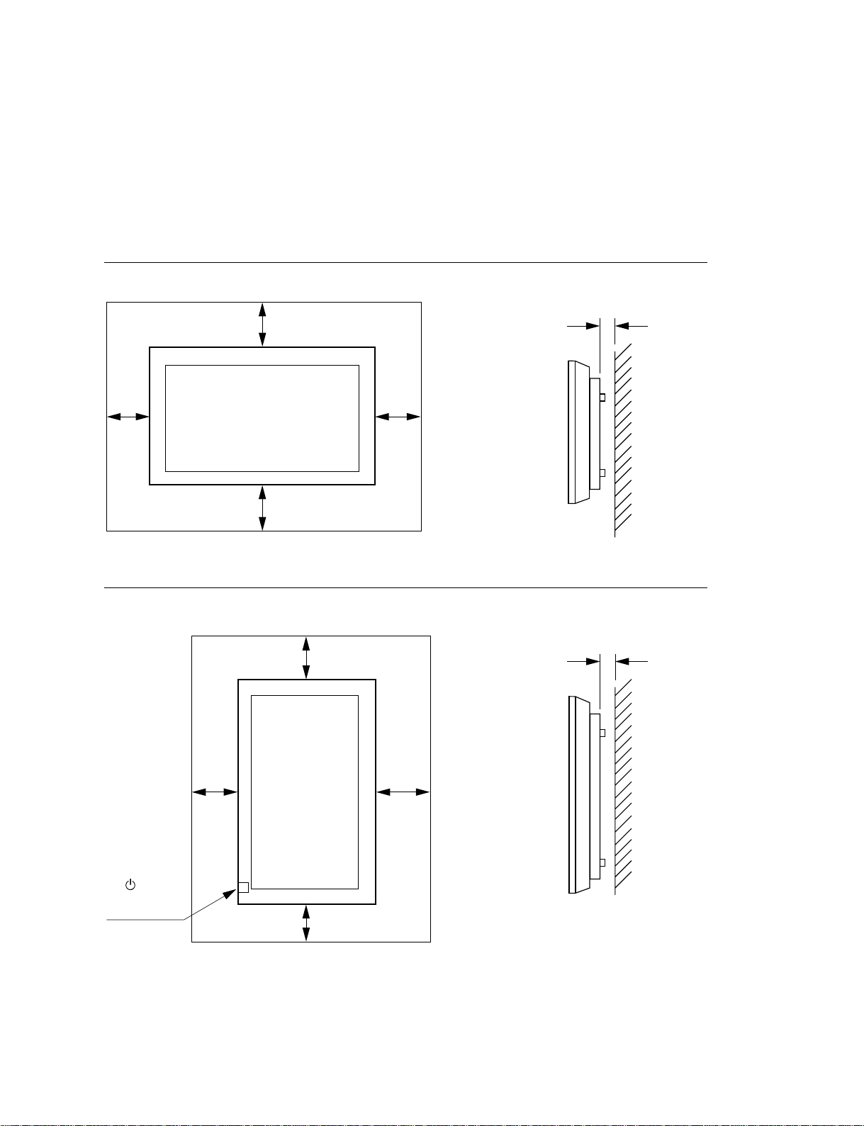
Caution
Provide an ample amount of space around the display
. When you set up the Display Unit, make sure there is more space around the display than that shown in
the figure below. This will allow for proper ventilation.
. Wile the unit is on, a certain amount of heat builds up inside. This can cause burns. Avoid touching the
top or rear of the unit when it is powered on or just after it has entered standby mode.
When mounting the display horizontally
2.5 (1)
25 (9 7/8)
10
(4)
7
25 (9
/8)
When mounting the display vertically
20 (4)
20
(9 7/8)
10
(4)
Unit : cm (inches)
2.5 (1)
25
(9 7/8)
Make sure that
the POWER
switch is at the
lower right.
FWD-32LX2F
FWD-32LX2X
10 (4)
Unit : cm (inches)
3 (P)
Page 6

Page 7

Table of Contents
1. Service Overview
1-1. Appearance Figure ..........................................................1-1
1-2. Board Location ...............................................................1-1
1-3. Disassembly ....................................................................1-2
1-3-1. Cabinet Assembly .................................................1-2
1-3-2. Bezel Assembly/H1 Board/H2 Board/LOGO
Assembly ...............................................................1-3
1-3-3. A Board/JT Board .................................................1-4
1-3-4. G5 Board ...............................................................1-5
1-3-5. SP Board................................................................1-6
1-3-6. LCD Panel .............................................................1-7
1-4. Warning on Power Connection.......................................1-8
2. Troubleshooting
2-1. Judgment When No Image is Displayed ........................2-1
2-2. Self-Diagnosis Function .................................................2-1
5. Spare Parts
5-1. Notes on Repair Parts .....................................................5-1
5-2. Exploded Views.............................................................. 5-2
6. Diagrams
6-1. Overall Block Diagrams .................................................6-1
6-2. Frame Wiring.................................................................. 6-3
3. Circuit Description
3-1. A Board...........................................................................3-1
3-2. H1 Board.........................................................................3-2
3-3. H2 Board.........................................................................3-2
3-4. G5 Board.........................................................................3-3
4. Electrical Alignment
4-1. Service Mode ..................................................................4-1
4-1-1. Start .......................................................................4-1
4-2. White Balance Adjustment .............................................4-1
4-2-1. Preparation ............................................................4-1
4-2-2. Setting....................................................................4-1
4-2-3. Cool Adjustment ...................................................4-2
4-2-4. Neutral Adjustment ...............................................4-2
4-2-5. Warm Adjustment .................................................4-2
FWD-32LX2F
FWD-32LX2X
1
Page 8

Page 9
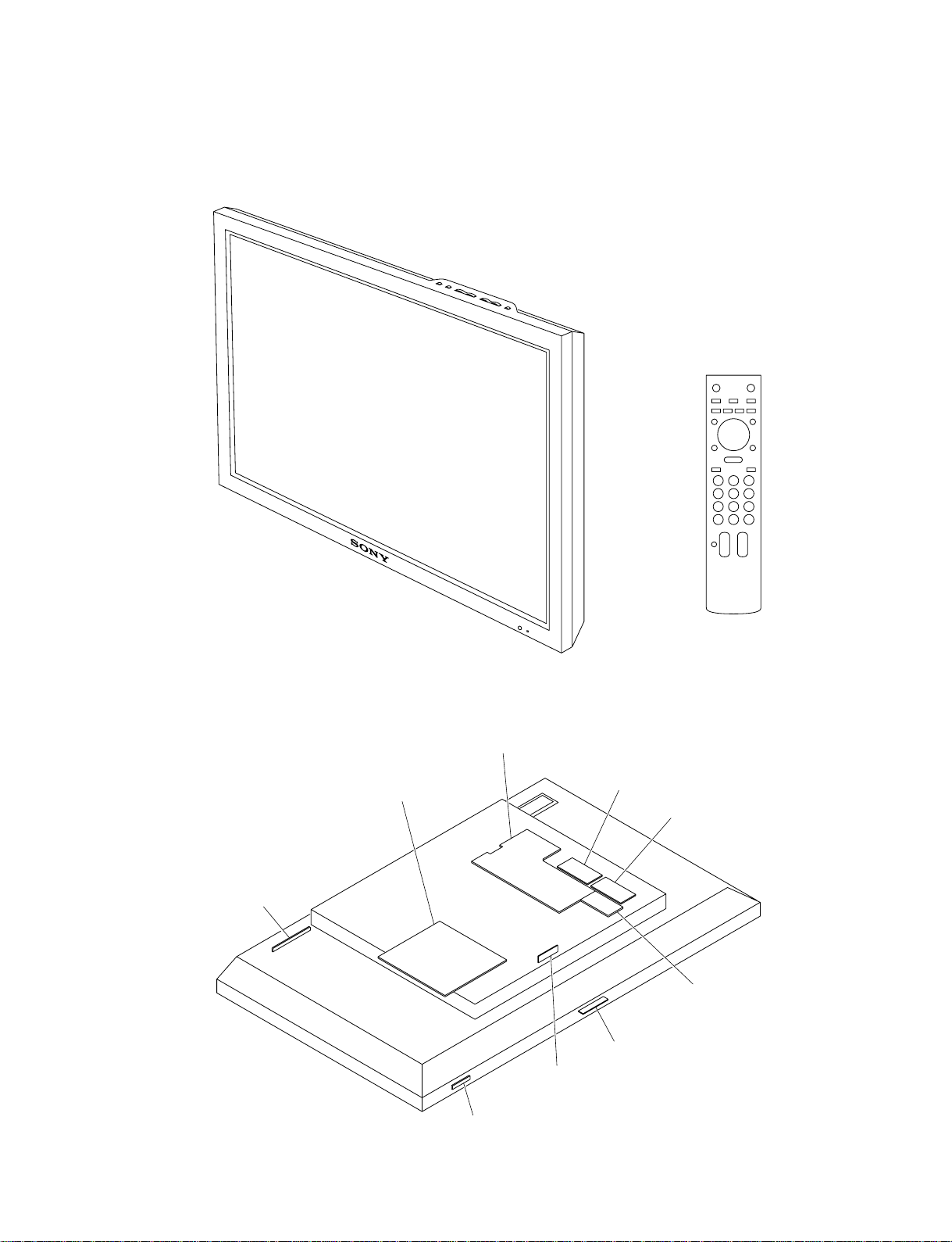
1-1. Appearance Figure
Section 1
Service Overview
1
2
3
4
5
6
7
8
9
SET
C
0
1-2. Board Location
H1 board
G5 board
A board
U20 board
U10 board
JT board
LOGO board
SP board
H2 board
FWD-32LX2F
FWD-32LX2X
1-1
Page 10
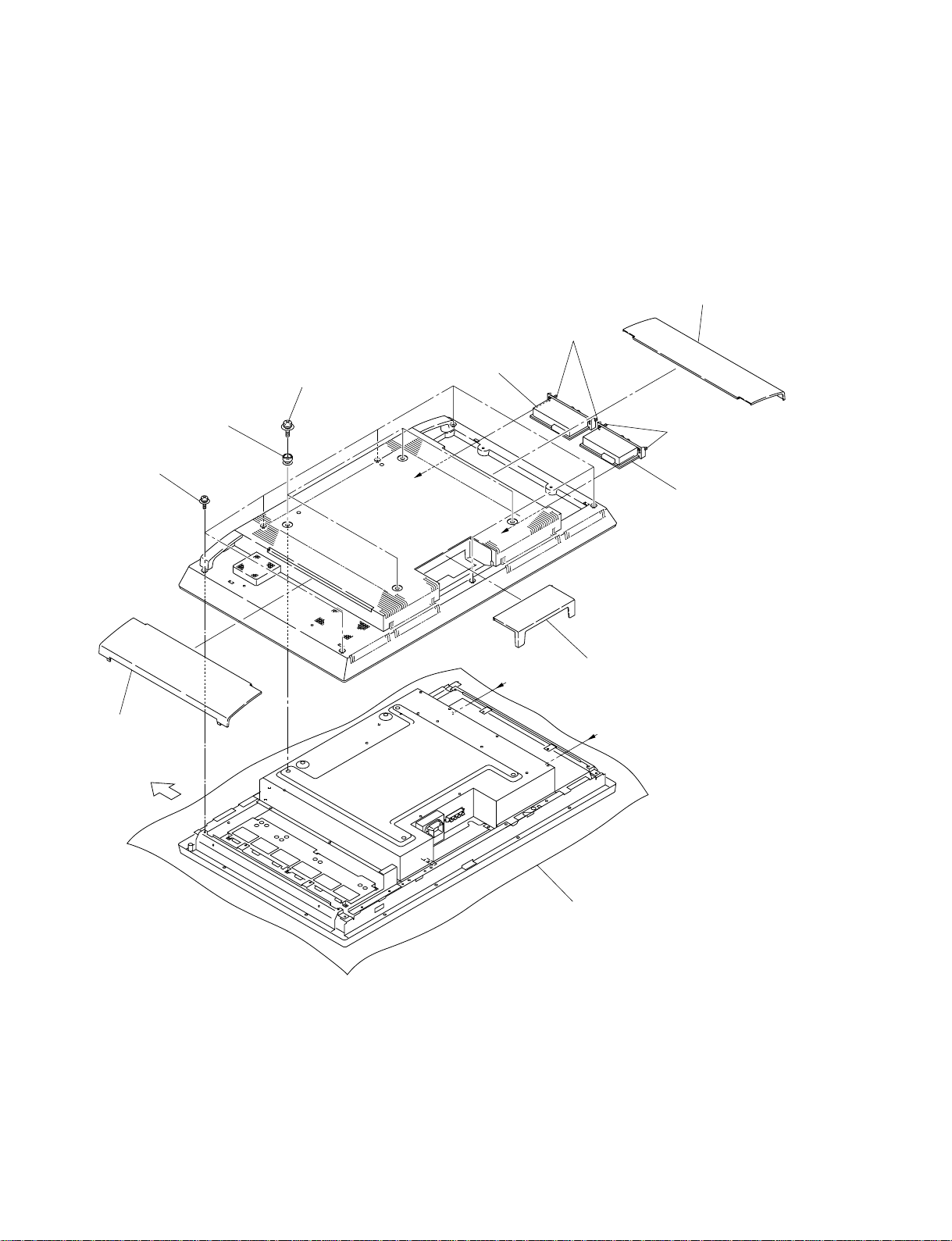
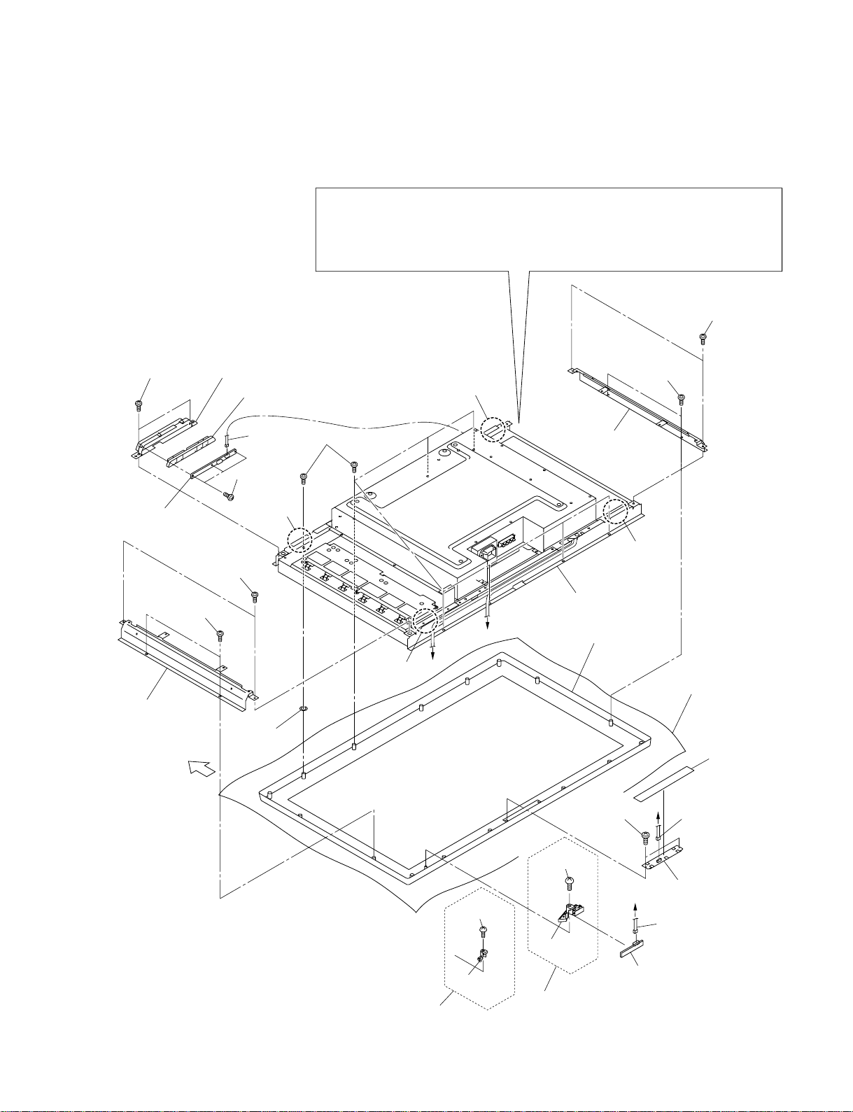
1-3. Disassembly
n
When removing/installing the cabinet and replacing the board, place the unit on the conductive cushion.
1-3-1. Cabinet Assembly
1 Side cable cover
3 Panel securing screws
9 Seven screws
1 Side cable cover
Upper side
8 Four knobs
7 Four screws
4 U20 block assembly
A
B
2 Bottom cable cover
A
5 Panel securing screws
6 U10 block assembly
B
1-2
Conductive cushion
FWD-32LX2F
FWD-32LX2X
Page 11
1-3-2. Bezel Assembly/H1 Board/H2 Board/LOGO Assembly
. Remove the cabinet assembly. (Refer to Section 1-3-1.)
m
. When removing the base chassis assembly, be sure to work with more than two persons.
. When removing the base chassis assembly, hold the four portions A and remove it from
the bezel assembly.
. Place the removed base chassis assembly on the conductive cushion.
7 Three screws
1 T wo screws
4 H1 board
8 Side frame
7 T wo screws
6 T wo screws
Upper side
2 Control button panel
5 Control button
KCN1
3 Three
screws
Portion A
9 Spacer
0 Eight screws
Portion A
B
Portion A
6 T wo screws
8 Side frame
Portion A
!- Base chassis
assembly
C
!, Bezel assembly
Conductive cushion
!\ Black tape
FWD-32LX2F
FWD-32LX2X
FWD-32LX2X
!= Screw
![ Light
guide
!; T wo screws
!= Screw
![ Light
guide
FWD-32LX2F/S
FWD-32LX2F/B
C
LCN1
B
!] H2 board
!' LOGO
ICN18
assembly
1-3
Page 12
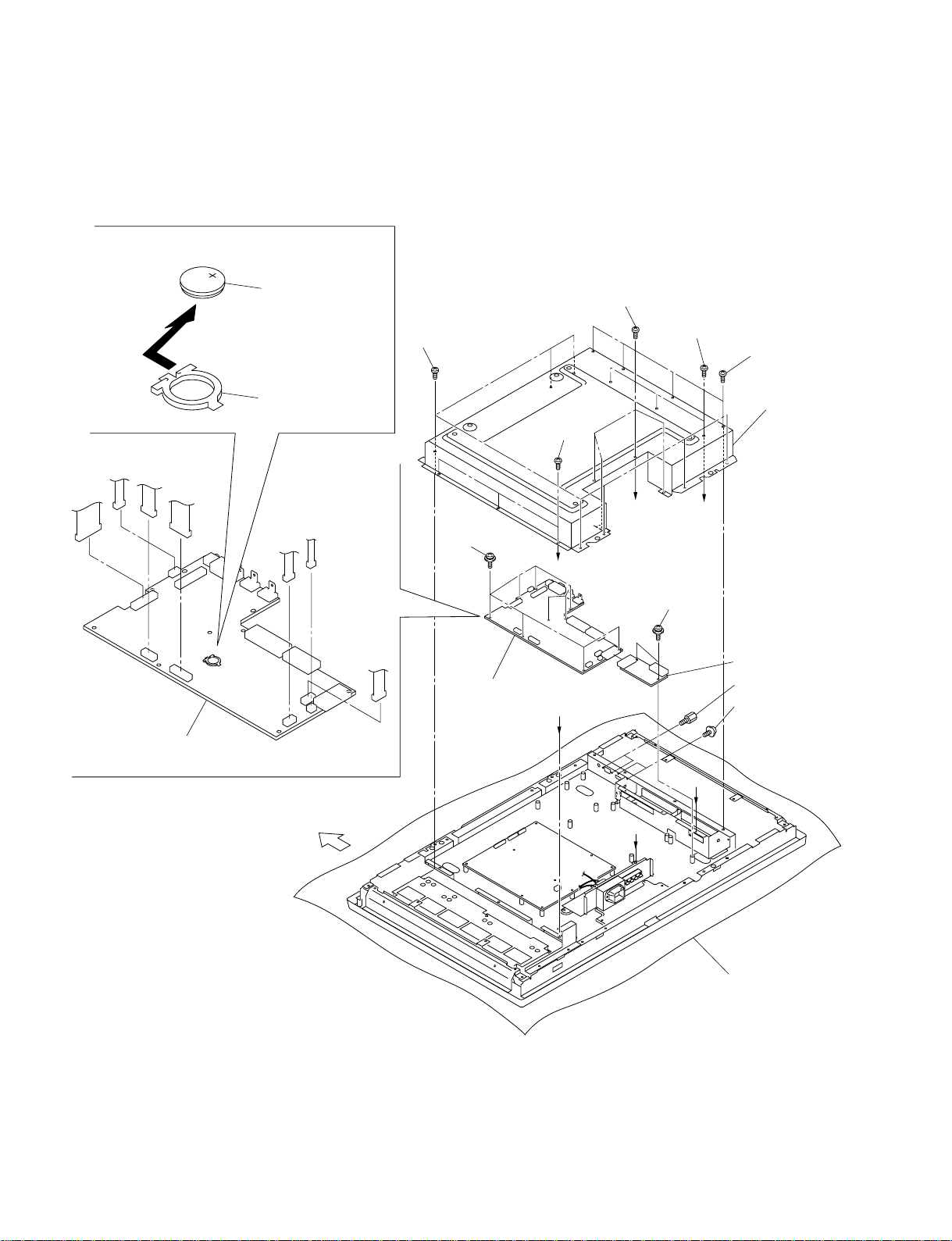
1-3-3. A Board/JT Board
. Remove the cabinet assembly. (Refer to Section 1-3-1.)
!= Removing the lithium battery.
Remove the lithium battery in the
direction of the arrow.
CN2
CN7
CN18
CN19
Lithium battery
(CR1220)
Battery holder
CN16
CN10
CN17
1 Seven screws
8 Nine screws
0 A board
3 Three
screws
C
C
2 Four screws
3 Three screws
A
9 T wo screws
4 Four screws
7 Shield cover
B
!- JT board
5 Two connector screws
6 T wo screws
1-4
0 A board
Upper side
B
A
Conductive cushion
FWD-32LX2F
FWD-32LX2X
Page 13

1-3-4. G5 Board
. Remove the cabinet assembly. (Refer to Section 1-3-1.)
. Remove the shield cover. (Refer to Section 1-3-3.)
CN923 CN924
CN921
2 G5 board
Upper side
1 Nine screws
2 G5 board
CN901
Conductive cushion
FWD-32LX2F
FWD-32LX2X
1-5
Page 14

1-3-5. SP Board
. Remove the cabinet assembly. (Refer to Section 1-3-1.)
. Remove the shield cover. (Refer to Section 1-3-3.)
Upper side
SCN2
2 SP board
1 T wo screws
Conductive cushion
1-6
FWD-32LX2F
FWD-32LX2X
Page 15

1-3-6. LCD Panel
. Remove the cabinet assembly. (Refer to Section 1-3-1.)
. Remove the bezel assembly. (Refer to Section 1-3-2.)
. Remove the A board. (Refer to Section 1-3-3.)
. Remove the G5 board. (Refer to Section 1-3-4.)
5 Frame (H)
Upper side
3 Four screws
2 LVDS cable
4 Base chassis assembly
1 Tape
9 Gasket
5 Frame (H)
FWD-32LX2F
FWD-32LX2X
6 LCD panel
8 Cushion (H)7 Cushion (V)
8 Cushion (H) 7 Cushion (V)
n
When replacing the LCD panel, be sure to replace
the two cushions (H) and two cushions (V).
Conductive cushion
Attaching position of gaskets
10mm
10mm
30mm
1-7
Page 16

1-4. Warning on Power Connection
Use the proper power cord for your local power supply.
United States, Continental Europe UK, Ireland, Australia, Japan
Canada New Zealand
Plug type VM0233 COX-07/636 –
Female end VM0089 COX-02/VM0310B VM0303B VM1313
Cord type SVT H05VV-F CEE (13) 53rd (O, C) HVCTF
Minimum cord 10 A/125 V 10 A/250 V 10 A/250 V 10 A/125 V
set rating
Safety approval UL/CSA VDE VDE DENAN-HO
1) Use an appropriate rating plug which complies with local regulations.
1)
VM1296
1-8
FWD-32LX2F
FWD-32LX2X
Page 17

Section 2
Troubleshooting
2-1. Judgment When No Image is
Displayed
The status in the case where “No image is displayed” is
displayed according to the number of times when the
POWER/STANDBY indicator in the lower-right position
of this unit’s front panel blinks in red. Blinking of two to
three times or five times is repeated after several seconds.
Number of blinking times Status
Two times An error code is detected from the
panel.
Three times When the sensor temperature
exceeds the allowable value
Five times 13 V power supply is detected.
Front side
2-2. Self-Diagnosis Function
The self-diagnosis function installed in this unit forcibly
shuts down this unit when the items below are detected
(abnormality is generated) or when the allowable value are
exceeded. The detected items and the allowable values are
as described below.
1. Panel error
This monitors the operation abnormality of a panel
inverter. This unit shuts down when the INV_DET signal
input from CN19 on the A board remains high after the
power is turned on.
2. Increase in sensor temperature
This detects the temperature of the A board and power
supply boards (G5 board). This unit shuts down when the
state in which the temperatures below were exceeded is
detected for two seconds or more.
. A board: 78 dC
. Power supply board: 86 dC
POWER/STANDBY
indicator
3. Abnormality of supply voltage
The DC voltage error detection in the A board is performed.
This unit is shut down when the voltage of 13 V becomes
6.9 V or less after the power is turned on.
The indicator flashes when an abnormal voltage is detected
for approximately 50 seconds. The power may be shut
down before the indicator starts flashing.
FWD-32LX2F
FWD-32LX2X
2-1
Page 18

Page 19

Section 3
Circuit Description
The main functions of each board in this unit are as
described below.
. A board
This board mounts an HD15 connector and two HDMI
connector interfaces. It processes a video signal together
with the signal from an option board using a scaler and
outputs data to the display panel. This board also outputs
the selected audio signal to the SP board.
. JT board
This is a relay board used for connecting the option
board and A board of slot 2.
. H1 board
This is a user interface board. This board mounts
[POWER], [INPUT]/[ENTER], [MENU], [UP],
[DOWN], [RIGHT], and [LEFT] buttons.
. H2 board
This board mounts two-color LED, which displays the
status of this unit, and a remote control photosensing
block.
. LOGO board
This is an LED board used for shining a SONY logo.
. SP board
This board mounts a speaker output terminal for audio
output.
. G5 board
This is a power board that has output voltages of STBY5
V, 5 V, 12 V, and 13 V.
3-1. A Board
The A board mounts HD15 (CN1), HDMI1 (CN12), and
HDMI2 (CN11) as a video input terminal. The signal from
option slot 1 is input from CN14, and the signal from
option slot 2 is input from CN13 through the JT board.
The RGB/YPbPr signals from HD15, and slots 1 and 2 are
directly input to a scaler circuit (U5). HDMI1 and HDMI2
signals are switched using an equalizer (U20), and the
selected TMDS signal is input to the scaler circuit. An
equalizer switches signals and controls the signal output,
by the port control (SEL_H and CE_H) from a scaler
circuit. The CVBS and Y/C signals from an option slot are
input through a p-type filter circuit to a scaler circuit. The
video signal from which an HDMI signal was eliminated is
input to a scaler circuit without passing through a switch
circuit. However, the RGB sync signals from slots 1 and
2, and HD15 are selected using a switching circuit (U3) by
HV_SA and HV_SB signals and input to a scaler circuit.
The input signal from HD15 is used for a video sync
signal. It is switched using a switching circuit (U4) by a
SYNC_MO signal and input to the port of a scaler circuit
that differs from the case of an H sync signal.
In a scaler circuit, resolution is converted according to the
display panel, and various picture qualities as well as wideangle setting or zoom setting are set and LVDS-transferred
to the panel through CN2.
FWD-32LX2F
FWD-32LX2X
There are the analog input from a mini-jack (CN3), slot 1,
or slot 2 and the digital input from HDMI in an audio
input. An analog audio signal is input to an audio processor circuit (U14). The audio signal from HDMI is output
from a scaler circuit as an I2S signal and input to U14. The
audio processor circuit is controlled by I2C to switch the
input and set the sound quality and volume. The selected
audio signal is passed through an amplifier circuit (U17)
and output to the SP board through CN10. The mini-jack
input cannot be only selected as the function of the main
unit only during HD15 input, but also it can be selected as
an audio input during conversion of DVI into HDMI. An
audio signal is muted by the software control of an audio
processor and the hardware control of an amplifier.
3-1
Page 20

This unit is used for BKM-FW20 that has RS-232C and
Control-S as an option board. The RS-232C (UART)
signal from an option slot is selected using a switching
circuit (U41). The signals from option slots 1 and 2 are
selected when OP1_RS_EN or OP2_RS_EN is set low on
the option side. OP1_RS_EN or OP2_RS_EN is low
during initial setting of BKM-FW20. Slot 2 has priority
when both OP1_RS_EN and OP2_RS_EN are low. The
selected RS-232C signal is connected to the control port or
firmware write port of a scaler circuit using a switching
circuit (U31). It is switched to the firmware write port
position when an FWE signal is set low on the option side
as the control of U31. The FWE signal is high during
initial setting of BKM-FW20. The signal (IR) from a
remote control photosensing block is shifted in level to a
signal (IRO) of 5 V to 3.3 V using U27, branching to each
option slot connector. The Control-S signals (OP1_IRI
and OP2_IRI) from the IRO signal and each option slot are
input to a switching circuit (U29), selected, and input to
the IR port of a scaler circuit. Which signal to select is
determined by controlling the OP1_S_EN and OP2_S_EN
signals from each option. When BKM-FW20 is not
connected, each signal is set high and an IRO signal is
selected. The IRI signal from each slot is selected when
OP1_S_EN and OP2_S_EN signals are set low. Slot 2 has
priority when both OP1_S_EN and OP2_S_EN signals are
low. The OP1_S_EN and OP2_S_EN signals are low
during initial setting of BKM-FW20.
The A board mounts a real time clock circuit (U11). The
real time clock circuit is controlled by I2C. A timer
function is controlled based on the time read operation by
polling from a scaler. During timer correction, a timer is
adjusted to an error of 3 ppm by outputting a pulse of 1 Hz
to CN8 and putting a correction value in the register of IC
according to the obtained measurement value. The
corrected value is obtained in the adjustment stage of a
single board at a factory and stored in memory. It is not
lost even in the state in which the power is not connected.
A button battery is connected to RTC. Even with the AC
power not connected, power is supplied to IC so that U11
operates continuously.
A PWM signal (LOGO_PWM) is output from a scaler
circuit to the LOGO board that shines a SONY logo. The
output signal of an amplifier circuit (U28) is integrated to
drive LED on the LOGO board as a DC signal. This LED
is turned on and off using the LOGO_EN signal from a
scaler circuit.
An option board is discriminated by discriminating
OP1_SENSE1, OP1_SENSE2, OP2_SENSE1, and
OP2_SENSE2 signals at the ADC port of a scaler circuit
using a voltage. These signals are passed through IC
(U30) and switched using the control signals (Q_SEL1 and
Q_SEL2) from the scaler circuit. Only when the power is
turned on, these signals are switched and the option board
is discriminated. After that, the output signal U30 is
switched to power temperature (PS_TEMP) and polled as a
self-diagnosis function.
3-2. H1 Board
A button input signal is sent to the A board as a DC
voltage signal. 1 V, 1.5 V, and 2.2 V are sent to an
ADC_IN2 signal when you press the [MENU], [INPUT],
and [LEFT] buttons. 1 V, 1.5 V, and 2.2 V are sent to an
ADC_IN1 signal when you press the [RIGHT], [DOWN],
and [UP] buttons. 0 V is sent when you press only the
[POWER] button as a PWR_KEY signal. Each signal is
set to 3.3 V when you press no button.
3-3. H2 Board
The H2 board mounts an infrared remote control photosensor (IU1) and sends data to the A board as an IR signal.
This board also mounts two-color LED (ID5) that displays
the status of this unit. The LED controls light emission by
controlling the cathode.
The backlight of LCD is controlled by the PWM signal
(BL_CONT) from a scaler circuit. The PWM signal is
inverted using Q20, integrated using R373 and C356, and
output to CN19 as a DC signal (INV_ADJ). The On/Off
signal (PBIAS) of a panel inverter is output from the
dedicated port of a scaler and then output from CN19 as an
INV_ON signal.
3-2
FWD-32LX2F
FWD-32LX2X
Page 21

3-4. G5 Board
AC input/rectification block
CN901 on the G5 board is connected to an AC inlet and
AC power is input from the AC inlet. The input AC power
is passed through an AC noise filter consisting of C908,
C949, C971, L901, L902, and L908 and bridge-rectified
using BD901.
PFC converter
AC power is rectified using BD901 and the power factor is
improved using a PFC converter consisting of Q901,
IC901, L904, D901, D902, and C907. Moreover, an
output voltage is increased and stabilized to 390 VDC.
The smoothed output voltage is supplied to a standby
converter and main converter.
Standby converter
5 V (5 V and 5 VS) and 12 V are output from a switching
converter consisting of IC903 and T902. 5 V is output
from CN924 (pins 2 to 4), and 5 VS is output from CN924
(pin 8). 12 V is output from CN923 (pins 6 and 7).
During standby, however, the output voltage that is not
increased, but smoothed is supplied from a PFC converter.
Main converter
24 V and 13 V are output from a switching converter
consisting of IC902, Q902, and T901. 24 V is output from
CN921 (pins 1 to 5), and 13 V is output from CN923 (pins
2 and 3).
Main ON/OFF control
A PFC converter and main converter are turned on and off
by CN924 (pin 1) when a PS signal is set high and low
using a microcomputer. Q915 is turned on when a PS
signal is high. A PFC converter is turned on when Q914 is
turned on. A main converter is started when Q910 is
turned on after Q914 is turned on. Q915 is turned off
when a PS signal is low. A PFC converter and main
converter stop operation when Q914 and Q910 are turned
off.
FWD-32LX2F
FWD-32LX2X
3-3
Page 22

Page 23

Section 4
Electrical Alignment
4-1. Service Mode
4-1-1. Start
1. Input any signal to this unit.
2. Turn on the power of this unit.
3. Perform the operation below using a remote controller
(RM-FW001) supplied for this unit with OSD not
displayed.
(1) Press the button two times.
(2) Press the [MUTING] button.
(3) Press the button.
(4) Press the [MUTING] button.
(5) Press the [MENU] button.
The service mode is started.
4-2. White Balance Adjustment
This unit is adjusted to the prescribed white balance during
factory setting. The average value of white balance is
written in the A board during factory setting. (AD calibration has also been adjusted during factory setting.)
Perform the adjustment in this section when white balance
adjustment is required.
Initial values of A board
RED GREEN BLUE RED GREEN BLUE
**
*1
**
COOL 235 223 255 124 125 125
NEUTRAL 253 238 250 123 123 125
WARM 255 235 222 123 123 125
*1: GAIN
*2: OFFSET
4-2-1. Preparation
Required equipment
**
*1
**
**
*1
**
**
*2
**
**
*2
**
**
*2
**
. Signal generator
n
It is recommended to use 480i (HD15 Component) as a
connection signal. However, the signal to be actually
input can also be used.
. Color thermometer
Preparation
1. Input a signal to this unit and age for 30 minutes or
more.
4-2-2. Setting
1. Start the service mode. (Refer to Section 4-1-1.)
2. Select “HD15” by “INPUT SOURCE” in a menu.
n
Select according to the input signal when inputting any
signal.
n
To exit this screen, press the [MENU] button.
FWD-32LX2F
FWD-32LX2X
4-1
Page 24

4-2-3. Cool Adjustment
4-2-5. Warm Adjustment
1. Select “COOL” by “Color Temperature” in a menu.
2. Put the sensor of a color thermometer to the center of
the screen.
3. Input a fully white signal of 65% (IRE).
4. Change the R GAIN, G GAIN, and B GAIN values in
a menu and adjust so that x and y satisfy the specifications below.
COOL:
x = 272 ±1, y = 277 ±1
5. Input a fully white signal of 25% (IRE).
6. Change the R OFFSET, G OFFSET, and B OFFSET
values in a menu and adjust so that x and y satisfy the
specifications below.
COOL:
x = 274 ±3, y = 268 ±3
7. Repeat steps 3 to 6 to keep balance.
8. Exit the service mode using a [MENU] button.
The adjustment data is saved.
4-2-4. Neutral Adjustment
1. Select “Warm” by “Color Temperature” in a menu.
2. Put the sensor of a color thermometer to the center of
the screen.
3. Input a fully white signal of 65% (IRE).
4. Change the R GAIN, G GAIN, and B GAIN values in
a menu and adjust so that x and y satisfy the specifications below.
WARM:
x = 304 ±1, y = 315 ±1
5. Input a fully white signal of 25% (IRE).
6. Change the R OFFSET, G OFFSET, and B OFFSET
values in a menu and adjust so that x and y satisfy the
specifications below.
WARM:
x = 305 ±3, y = 308 ±3
7. Repeat steps 3 to 6 to keep balance.
8. Exit the service menu using a [MENU] button.
The adjustment data is saved.
1. Select “NEUTRAL” by “Color Temperature” in a
menu.
2. Put the sensor of a color thermometer to the center of
the screen.
3. Input a fully white signal of 65% (IRE).
4. Change the R GAIN, G GAIN, and B GAIN values in
a menu and adjust so that x and y satisfy the specifications below.
NEUTRAL:
x = 285 ±1, y = 294 ±1
5. Input a fully white signal of 25% (IRE).
6. Change the R OFFSET, G OFFSET, and B OFFSET
values in a menu and adjust so that x and y satisfy the
specifications below.
NEUTRAL:
x = 285 ±3, y = 284 ±3
7. Repeat steps 3 to 6 to keep balance.
8. Exit the service mode using a [MENU] button.
The adjustment data is saved.
4-2
FWD-32LX2F
FWD-32LX2X
Page 25

5-1. Notes on Repair Parts
1. Safety Related Components Warning
w
Components marked ! are critical to safe operation.
Therefore, specified parts should be used in the case of
replacement.
2. Standardization of Parts
Some repair parts supplied by Sony differ from those
used for the unit. These are because of parts commonality and improvement.
3. Stock of Parts
Parts marked with “o” at SP (Supply Code) column of
the spare parts list may not be stocked. Therefore, the
delivery date will be delayed.
Section 5
Spare Parts
4. Harness
Harnesses with no part number are not registered as
spare parts.
The components identified by mark contain confidential
information.
Strictly follow the instructions whenever the components
are repaired and/or replaced.
FWD-32LX2F
FWD-32LX2X
5-1
Page 26

Cover Block
5-2. Exploded Views
2
PSW
M6 x 20
9
10
14
A
9
1
B
4
8
C
11
16
17
7
13
13
A
13
12
B
BVTP
3 x 8
C
12
13
18
19
BVTP
3 x 8
15
5
3
15
FWD-32LX2X
FWD-32LX2F/S
FWD-32LX2F/B
6
5-2
FWD-32LX2F
FWD-32LX2X
Page 27

No. Part No. SP Description
1 A-1215-079-A o U10 BLOCK ASSY
2 A-1215-080-A o U20 BLOCK ASSY
3 X-2149-780-1 s BEZEL ASSY (FOR FWD-32LX2F/S)
X-2159-379-1 s BEZEL ASSY (FOR FWD-32LX2F/B)
X-2025-243-6 s BEZEL ASSY (FOR FWD-32LX2X)
4 X-2149-781-1 s CABINET ASSY
5 1-789-684-11 s MOUNTED CIRCUIT BOARD, LOGO
6 1-789-685-11 s MOUNTED CIRCUIT BOARD, H2
7 1-789-686-11 s MOUNTED CIRCUIT BOARD, H1
8 2-159-508-11 s CABLE COVER BOTTOM
9 2-179-449-11 s CABLE COVER SIDE
10 2-580-602-01 s SCREW, +PSW M4X12
11 2-580-628-01 s SCREW, +BVST 3X6
12 2-580-630-01 s SCREW, +BVST 4X8
13 2-580-639-01 s SCREW, +BVTP2 4X12
14 2-667-019-01 s HOOK
15 2-681-589-21 s LIGHT GUIDE (FOR FWD-32LX2F/S)
2-681-589-31 s LIGHT GUIDE (FOR FWD-32LX2F/B)
2-159-493-02 s LIGHT GUIDE (FOR FWD-32LX2X)
16 2-697-732-01 s CONTROL BUTTON PANEL
17 2-697-733-01 s CONTROL BUTTON
18 2-889-538-01 s SPACER
19 3-254-058-01 s SCREW
Cover Block
7-628-000-10 s SCREW +PSW M6X20
7-685-646-79 s SCREW +BVTP 3X8 TYPE2 IT-3
FWD-32LX2F
FWD-32LX2X
5-3
Page 28

Chassis Block
112
111
111
111
112
117
109
116
101
103
117
110
104
119
108
114
B
A
C
102
108
111
B
105
118
106
108
108
A
119
BVTP
3 x 8
107
115
109
117
C
5-4
116
113
116
117
116
FWD-32LX2F
FWD-32LX2X
Page 29

No. Part No. SP Description
101 ! 1-523-000-11 s TIME LUG FUSE (3.15A/250V)
102 ! 1-756-157-11 s BATTERY, LITHIUM
103 1-789-675-11 s MOUNTED CIRCUIT BOARD, G5
104 1-789-677-11 s MOUNTED CIRCUIT BOARD, A
(FOR FWD-32LX2F/S, FWD-32LX2F/B)
1-789-679-11 s MOUNTED CIRCUIT BOARD, A
(FOR FWD-32LX2X)
105 1-789-682-11 s MOUNTED CIRCUIT BOARD, SP
106 1-789-683-11 s MOUNTED CIRCUIT BOARD, JT
107 ! 1-820-824-11 s AC INLET
108 2-580-593-01 s SCREW, +PSW M3X8
109 2-580-598-01 s SCREW, +PSW M3X30
110 2-580-600-01 s SCREW, +PSW M4X8
111 2-580-628-01 s SCREW, +BVST 3X6
112 2-580-630-01 s SCREW, +BVST 4X8
113 1-802-237-11 s LCD PANEL 32INCH WXGA TFT
114 2-890-185-01 s WIRE SADDLE
115 2-990-241-02 s HOLDER (A), PLUG
116 3-094-314-01 o CUSHION (H)
117 3-094-315-01 o CUSHION (V)
118 4-083-966-01 s SCREW, HEXAGON
119 2-898-753-01 s GASKET
Chassis Block
FWD-32LX2F
FWD-32LX2X
5-5
Page 30

Packing Block
208
201
204
202
212
205
213
214
210
206
207
203
209
No. Part No. SP Description
201 1-479-983-11 s REMOTE COMMANDER (RM-FW001)
202 9-885-099-05 s BATTERY COVER (FOR RM-FW001)
203 1-566-316-11 s CONNECTOR, CONVERSION
204 1-830-712-11 s CONNECTION CABLE (VIDEO CABLE)
205 X-2176-504-1 s CABLE HOLDER, PACKING, 6P
206 2-890-214-01 s MANUAL,INSTRUCTION
(JAPANESE, ENGLISH, FRENCH,
GERMAN, SPANISH, ITALIAN,
SIMPLIFIED CHINESE)
207 2-890-253-01 s ACCESSORY BOX
208 2-890-254-01 s CUSHION (UPPER)
209 2-890-255-01 s CUSHION (LOWER)
210 2-890-256-01 s PROTECTION BAG
211 2-890-257-01 s INDIVIDUAL CARTON
212 2-990-242-01 s HOLDER (B), PLUG
213 3-613-640-01 o PLUG,HOLDER C
214 ! ------------ CORD, POWER
(See Sec.1-4. Warning on Power Connection)
5-6
211
FWD-32LX2F
FWD-32LX2X
Page 31

SS-SP32FW
BVTP
4 x 12
BVTP
4 x 12
Overall Block
PSW
4 x 10
PSW
4 x 10
BVTP
4 x 12
301
BVTP
4 x 12
No. Part No. SP Description
301 A-1081-105-A s SPEAKER ASSY (32R) (RP)
(FOR SS-SP32FW/S (SILVER))
A-1083-767-A s SPEAKER ASSY (32R) (RP)
(FOR SS-SP32FW/W (PEARL WHITE))
302 A-1081-106-A s SPEAKER ASSY (32L) (RP)
(FOR SS-SP32FW/S (SILVER))
A-1083-768-A s SPEAKER ASSY (32L) (RP)
(FOR SS-SP32FW/W (PEARL WHITE))
302
7-682-962-09 s SCREW +PSW 4X10
7-685-661-79 s SCREW +BVTP4X12(EP-FE/ZNBK/CM2)
FWD-32LX2F
FWD-32LX2X
5-7
Page 32

Board Connections
TOP SIDE
H1 Board
CHN1
CHN2
CHN3
CHN4
CHN5
CHN6
H2 Board LOGO Board
KCN1
INVERTER Board
J1
ICN18
6
4
CN921 CN923 CN924
G5 Board
CN901
J3 J4 J5 J6
CTRL Board
CN101
5
LCN1
2
3
SP Board
SCN2
1
CN7
CN2
CN4
CN18
CN19
A Board
CN17
CN16
CN10
8
JT Board
7
No. Part No. SP Description
1
1-910-031-71 s CONNECTOR ASSY (LVDS)
2
1-910-031-84 o CONNECTOR ASSY 8P MAIN
3
1-910-031-85 o CONNECTOR ASSY 12P MAIN
4
1-910-031-86 o CONNECTOR ASSY 14P POWER
5
1-910-031-87 o CONNECTOR ASSY 7P IR
6
1-910-031-88 o CONNECTOR ASSY 5P KEY
7
1-910-031-89 o CONNECTOR ASSY 3P LOGO
8
1-910-031-90 o CONNECTOR ASSY 4P SP
5-8
FWD-32LX2F
FWD-32LX2X
Page 33

6-1. Overall Block Diagrams
Overall (1/2)Overall (1/2)
Section 6
Diagrams
HDMI1
HDMI2
HD15
OPTION1
(U10 BLOCK)
AU
JACK
RGB/YPbPr
YC
CVBS
HDMI1
HDMI2
PC_R/G/B
HS/PC_VS
HS
SELECTOR
PC_VS
OP1_HS/VS
OP2_HS/VS
HDMI_EQ
HDMI
CE_H
SEL_H
PC_CVBS
PC_HS VGA_HS/VS
L: H/V , H: VIDEO
SYNC_MODE
OP1_PY/PB/PR
OP2_PY/PB/PR
H: ENABLE, L: DISABLE
H: HDMI1, L: HDMI2
FOR SCART(RGB)
OP1_Y/C
OP1_CVBS
PC_HS/VS
LPF
SELECTOR
LPF
AB : SEL
LL : HD15
HL : OP1
LH : OP2
HV_SA
HV_SB
2
C_NVM
I
2
I
C_3.3v
2
C_5v
I
CORTEZ PLUS
MSTR0_SCL/SDA
MSTR1_SCL/SDA
MSTR2_SCL/SDA
HDMI_INPUT PORT
A/B/C_4
A/B/C_2
A_1/SV_3
SV_4
A/B/C_3
B_1/C_1
SV_2
SV_1
HS/VS
LVDS
LCD
PANEL
DDRx2
FWD-32LX2F
FWD-32LX2X
OPTION2
(U20 BLOCK)
H/V
AUDIO 1
RGB/YPbPr
YC
CVBS
H/V
AUDIO 1
OP2_Y/C
OP2_CVBS
PC_L/R
AU1_L/R
AU2_L/R
LPF
LPF
2
S_WS/DA/CL
I
L: RESET , H: NORMAL
RESET
AUDIO
PROCESSOR
6-1
SPK_L/R
MUTE
6-1
D-AMP
L: MUTE
H: NORMAL
AUDIO_L/R
2
I
C_5V
2
C_5V
I
I2C_NVM
2
C_3.3V
I
TEMP
2
S_OUT
I
NVM
RTC
SIGNAL & I2C BLOCK
Overall (1/2)
Page 34

Overall (2/2) Overall (2/2)
2
I
C
NVM
2
I
C TRANS
HDMI1
HDMI2
HD15
OPTION1
(U10 BLOCK)
RS_OUT_EN
UART
S_OUT_EN
SIRCS IN
SIRCS OUT
QSENSE
RESET
ALARM
IR
5V 8 3.3V
CE_REMOTE1
2
C
I
CE_REMOTE2
2
C
I
TX/RX_PC
LEVEL
SHIFT
HP_DET1
HP_DET2
NVM
VGA_CAB
NVM
OP1_TX/RX
OP2_TX/RX
EDID2
INPUT H: PULG IN, L: NC
OUTPUT L: CONNECT REQUEST
INPUT H: PULG IN, L: NC
OUTPUT L: CONNECT REQUEST
2
C TRANS
I
EDID3
H: NC, L: PULG IN
2
C TRANS
I
EDID1
UART
SELECTOR
NAND
TX/RX
N_RS_
RCV_EN
OP_
RS_EN
SELECTOR
VGA_SDA/SCL
UART
SELECTOR
N_OP_RS_EN
NOT
DSCA/DSCL_COM
CE_REMOTE
SEL_H
IRO
OP1_IRI
OP2_IRI
RS_RCV_E
L: OP1 or OP2(NORMAL)
H: OP1 5 OP2
H: HDMI1, L: HDMI2
OP2_S_EN
IR
SELECTOR
OP1_S_EN
IRDATA
OP1 OP2 SEL
L L OP2
L H OP1
H L OP2
H H IRO
TXD/RXD
CORTEZ PLUS
VGA0_SDA/SCL
VGA1_SDA/SCL
UDI/O_0
BDATA11
IR0
LBADC_3/4
CONTROLLED_DEVICE_SDA
CONTROLLED_DEVICE_SCL
GPIO
LBADC_IN1/2
OCM_TIMER
OCM_CS1
BDATA14
PWM2
IPCLK3
IPCLK3
PWM0
PWER-KEY
ADC_IN1/2
LED_G1
LED_R1
LED_G2
LED_R2
L: OFF, H: ON
LOGO_EN
LOGO_PWM
RESET
L: RESET
H: NORMAL
INV_DET
L: ABNORMAL or OFF
H: NORMAL ON
BL_CONT
KEY
LED
L: OFF, H: ON
TO LOGO CIR
TO AUDIO DEC
LCD
PANEL
OPTION2
(U20 BLOCK)
RS_OUT_EN
UART
S_OUT_EN
SIRCS IN
SIRCS OUT
QSENSE
RESET
ALARM
OP1_QSENSE1/2
OP2_QSENSE1/2
GRESET
ALARM: PULSE OUT
UART
SELECTOR
SENSE1/2
QSENSE
SELECTOR
L: RESET , H: NORMAL
Q_SEL1
Q_SEL2
SEL1 SEL2 SELECT
L L OP1
H L OP2
6-2
6-2
RESET
POWER_OFF
TO POWER SUPPLY
FOR AUDIO AMP
DIPEXTCOAST
PPWERBDATA16
AU_ON
PPWR
FOR PANEL LOGIC POWER
FOR PANEL INSERTER POWER
PBIAS
PBIAS
CONTROL BLOCK
Overall (2/2)
FWD-32LX2F
FWD-32LX2X
Page 35

Frame Wiring Frame Wiring
LCD PANEL
6-2. Frame Wiring
AC INLET
H1
G5
CN921
+24V
1
2
+24V
3
+24V
4
+24V
5
+24V
6
GND
7
GND
8
GND
9
GND
10
GND
11
DET
12
INV ON/OFF
13
DIM
14
N/A
CN901
1
L
N.C
2
N
3
KCN1
1
ADC_IN2
2
GND
3
ADC_IN1
4
GND
5
PWR_KEY
CN923
1
DET
2
13V
3
13V
4
GND
5
GND
6
12V
7
12V
8
GND
9
GND
10
PS_TEMP
DIM
CN924
5VD
5VD
5VD
GND
GND
GND
5VS
11
12
1
2
3
4
5
6
7
8
INV ON/OFF
PS ON/OFF
Note: The components identified by mark contain confidential
information.
Strictly follow the instructions whenever the components
are repaired and/or replaced.
A
CN7
ADC_IN2
1
2
GND
3
ADC_IN1
4
GND
5
PWR_KEY
CN19
1
INV_DET
2
13V-G
3
13V-G
4
5
6
12V-G
7
12V-G
8
9
10
PS_TEMP1
11
INV_ON
12
INV_ADJ
13
CN18
1
POWER_OFF
2
5V-G1
3
5V-G1
4
5V-G1
5
6
7
8
5V-G1
GND
GND
GND
GND
NC
GND
GND
GND
CN2
1
NC
2
NC
3
NC
4
GND
5
TXA10-
6
TXA10+
7
GND
8
TXA11-
9
TXA11+
10
GND
11
TXA12-
12
TXA12+
13
GND
14
TXA1C-
15
TXA1C+
16
GND
17
TXA13-
18
TXA13+
19
GND
20
RESERVED
ROTATE
GND
GND
GND
5V
5V
5V
5V
5V
21
22
23
24
25
26
27
28
29
30
LVDS OPITON
J1
+24V
1
2
+24V
3
+24V
4
+24V
5
+24V
6
GND
7
GND
8
GND
9
GND
10
GND
11
Panel_DET
12
BL_ON
13
VDIM
14
GND(NC)
CN101
1
NC
2
NC
3
NC
4
GND
5
RxIN0-
6
RxIN0+
7
GND
8
RxIN1-
9
RxIN1+
10
GND
11
RxIN2-
12
RxIN2+
13
GND
14
RXCLKIN-
15
RXCLKIN+
16
GND
17
RxIN3-
18
RxIN3+
19
GND
20
RESERVED
21
LVDS OPITON
22
ROTATE
23
GND
24
GND
25
GND
26
5V_PANEL
27
5V_PANEL
28
5V_PANEL
29
5V_PANEL
30
5V_PANEL
INVERTER
CTRL
1
2
3
SP
SCN2
L+
SPEAKER
SPEAKER
H2
GND(FOR EARTH)
LOGO
FWD-32LX2F
FWD-32LX2X
LRR+
ICN18
RED
GREEN
NC
NC
IR
5V
GND
LCN1
5V
GND
LOGO_ON
GND
1
2
3
4
1
2
3
4
5
6
7
8
CHASSIS GND
1
2
3
4
CHASSIS GND
A BCDEFGH
CN10
AUDIO_L+
1
2
AUDIO_L-
3
AUDIO_R-
4
AUDIO_R+
CN17
1
2
3
4
5
6
7
8
9
CN16
1
2
3
LOGO_ON
GND
5V-G
IR
NC
NC
GREEN2
RED2
NC
NC
5V
GND
6-3
JT
4
U20
5
U10
Frame Wiring
6-3
Page 36

Page 37

SAFETY CHECK-OUT
After correcting the original service problem,
perform the following safety checks before
releasing the set to the customer :
Check the metal trim, “metallized” knobs, screws,
and all other exposed metal parts for AC
leakage. Check leakage as described below.
LEAKAGE TEST
The AC leakage from any exposed metal part to
earth ground and from all exposed metal parts to
any exposed metal part having a return to
chassis, must not exceed 3.5 mA. Leakage
current can be measured by any one of three
methods.
1. A commercial leakage tester, such as the
Simpson 229 or RCA WT-540A. Follow the
manufacturers’ instructions to use these
instruments.
2. A battery-operated AC milliammeter. The
Data Precision 245 digital multimeter is
suitable for this job.
3. Measuring the voltage drop across a resistor
by means of a VOM or battery-operated AC
voltmeter. The “limit” indication is 5.25 V, so
analog meters must have an accurate lowvoltage scale. The Simpson 250 and Sanwa
SH-63Trd are examples of a passive VOM
that is suitable. Nearly all battery operated
digital multimeters that have a 20 V AC range
are suitable. (See Fig. A)
FWD-32LX2F
FWD-32LX2X
To Exposed Metal
Parts on Set
0.15 µF 1.5 k
Fig A. Using an AC voltmeter to check AC leakage.
Z
Earth Ground
AC
voltmeter
(5.25V)
Page 38

FWD-32LX2F (WW)
FWD-32LX2X (WW) E
9-834-144-02
Printed in Japan
Sony Corporation 2007. 2 22
©2006
 Loading...