

Page 1

2-891-221-07 (1)
Data Projector
特約店様用設置説明書 3〜9、42〜70 ページ
この特約店様用設置説明書には、レンズ の 交換方法、別売りのレンズ使用時や天井吊りの場合の設置寸法
など、製 品 の 設置時に必要な情報を記載しています。
お客様へ
この設置説明書は、特約店様用に書かれたものです。
お客様が設置説明書に記載された設置を行うと、事故などにより死亡や大けがにつながることがあります。お
客様自身では絶対に設置をしないでください。設置については必ずソニー使い方相談窓口にご相談ください。
特約店の方は、設置を安全に行うために、必ずこの説明書をよくお読みください。
Installation Manual for Dealers Pages 3, 10 to 13 and 42 to 70
This Installation Manual for Dealers explains how to install the projector. For example, it explains
lens replacement, installation measurements when using the optional lens and hanging the projector
from the ceiling.
Warning: This Installation Manual is for Dealers.
Manuel d’installation pour les revendeurs Pages 3, 14 à 18 et 42 à 70
Le manuel d’installation pour les revendeurs explique comment installer le projecteur. Par
exemple, il explique la procédure de remplacement de l’objectif, les dimensions d’installation
lorsque vous employez l’objectif en option et comment suspendre le projecteur au plafond.
Avertissement: Ce manuel d’installation est destiné aux revendeurs.
Manual de instalación para proveedores Páginas 3, 19 a 23 y 42 a 70
En este manual de instalación para proveedores se describe cómo instalar el proyector. Por
ejemplo, se describe cómo sustituir el objetivo, las medidas de instalación cuando se utiliza el
objetivo opcional y cómo colgar el proyector en el techo.
Advertencia: Este manual de instalación es para los proveedores.
Installationsanleitung für Händler Seite 3, 24 bis 28 und 42 bis 70
In dieser Installationsanleitung für Händler wird erläutert, wie Sie den Projektor installieren.
Beispielsweise werden das Austauschen des Objektivs, die Installationsabmessungen beim Verwenden
des gesondert erhältlichen Objektivs und das Installieren des Projektors an der Decke beschrieben.
Achtung: Diese Installationsanleitung richtet sich an Händler.
Manuale d’installazione per i rivenditori Pagine 3, 29 a 33 e 42 a 70
Il presente manuale contiene le istruzioni relative all’installazione del proiettore. Vengono riportate
ad esempio le istruzioni su come sostituire l’obiettivo, le misure di installazione quando si utilizza
l’obiettivo opzionale e le procedure dell’installazione al soffitto.
Avvertenza: Il presente manuale d’installazione è destinato ai rivenditori.
Руководство по монтажу для дилеров
В данном руководстве по монтажу для дилеров объясняется, как устанавливать
проектор. В частности, в нем объясняется, как выполнить замену объектива,
приведены установочные размеры при использовании дополнительного объектива и
подвешивании проектора к потолку.
Предупреждение: Данное руководство по монтажу предназначено для дилеров.
Стр. 3, c 34 по 37 и с 42 по 70
VPL-FE40/FE40L
VPL-FX40/FX40L
VPL-FX41/FX41L
VPL-FW41/FW41L
© 2006 Sony Corporation
Page 2
安全のために
ソニー製品は安全に充分配慮して設計されています。しかし、電気製品は、
まちがった使いかたをすると、火災や感電などにより死亡や大けがなど人身
事故につながることがあり、危険です。
事故を防ぐために次のことを必ずお守りください。
安全のための注意事項を守る
注意事項をよくお読みください。
警告表示の意味
この説明書および製品では、次
のような表示をしています。表
示の内容をよく理解してから本
文をお読みください。
定期点検をする
5年に1度は、内部の点検を、使い方相談窓口にご相談ください(有料)。
故障したら使わない
すぐに、使い方相談窓口にご連絡ください。
万一、異常が起きたら
・煙が出たら
・異常な音、におい
がしたら
・内部に水、異物が
入ったら
・製品を落としたり
キャビネットを破
損したときは
,
1電源を切る。
2電源コードや接続コードを抜く。
3使い方相談窓口に連絡する。
この表示の注意事項を守らない
と、火災や感電などにより死亡
や大けがなど人身事故につなが
ることがあります。
この表示の注意事項を守らない
と、感電やその他の事故により
けがをしたり周辺の物品に損害
を与えたりすることがありま
す。
注意を促す記号
行為を禁止する記号
行為を指示する記号
2
Page 3
日本語
English
Français
目次
警告 ..............................................
注意 ..............................................
電池についての安全上のご注意 ..........
本機の性能を保持するために ..............
概要 ....................................................
レンズ交換のしかた ............................
設置寸法 ...........................................
床置き ....................................................... 42
天井つり.................................................... 49
プロジェクターサスペンションサポートPSS-
610 の取り付けかた ........................... 56
床置き、ツインスタック .............................. 59
寸法図 ...............................................
Español
42
67
Índice
Precauciones ................................ 19
Introducción ................................. 20
Sustitución del objetivo............... 21
Diagrama de instalación .............. 42
Instalación en el suelo ....................... 42
Instalación en el techo ....................... 49
Instalación del soporte de suspensión
del proyector PSS-610 ................... 56
Instalación en el suelo para apilamiento
doble .............................................. 60
Dimensiones ................................. 67
Table of Contents
4
Precautions................................... 10
5
Overview ....................................... 11
6
Replacing the Lens ...................... 12
Installation Diagram ..................... 42
7
7
8
Floor Installation ............................... 42
Ceiling Installation ............................ 49
Attaching the Projector Suspension
Support PSS-610 ........................... 56
Floor Installation for Twin
Stacking ......................................... 59
Dimensions ................................... 67
Deutsch
Inhalt
Sicherheitsmaßnahmen............... 24
Übersicht....................................... 25
Austauschen des Objektivs ........ 26
Installationsdiagramm .................43
Installation am Boden ....................... 43
Installation an der Decke ................... 50
Anbringen der Projektoraufhängung
PSS-610 ......................................... 57
Installation am Boden für die
Doppelprojektion ........................... 60
Abmessungen .............................. 67
Table des matières
Précautions................................... 14
Aperçu ........................................... 15
Remplacement de l’objectif......... 16
Schéma d’installation .................. 42
Installation au sol .............................. 42
Installation au platfond ...................... 49
Fixation du support de suspension de
projecteur PSS-610 ........................ 56
Installation au sol en double
empilage ........................................ 59
Dimensions ................................... 67
Italiano
Indice
Precauzioni ...................................29
Presentazione ............................... 30
Sostituzione dell’obiettivo........... 31
Diagramma di installazione ......... 43
Installazione sul pavimento ............... 43
Installazione sul soffitto .................... 50
Applicazione del supporto di sospensione
del proiettore PSS-610 .........................
Installazione al pavimento per
impilazione .................................... 60
Dimensioni .................................... 67
57
Русский
Содержание
Меры предосторожности .......... 34
Обзор ............................................ 35
Замена объектива ...................... 36
Монтажная схема ....................... 43
Напольная установка .....................43
Потолочная установка ..................50
Прикрепление подвесного
устройства проектора
PSS-610 ..........................................57
Напольный монтаж cо сдвоенным
наложением ..................................61
Габаритные размеры .................. 67
3
Page 4
下記の注意を守らないと、
火災や感電により死亡や大けがに
つながることがあります。
指定された部品を使用する
指定以外の部品を使用すると、火災や感電および
故障や事故の原因となります。ランプ 、電池、天吊り
金具、レンズ 、フィルタは指定されたものを使用してく
ださい。指定以外の部品を使用する場合は、ソニー
のサービス担当者または営業担当者にご相談くださ
い。
通風孔をふさぐような場所に設置しない
通風孔をふさぐと内部に 熱 がこもり、火災や故障の
原因となることがあります。風通しをよくするために
次の項目をお守りください。
壁から30cm以上離して設置する。
•
密閉された狭い場所に押し込めない。
•
毛足の長い敷物(じゅうたんや布団など)の上に設
•
置しな い 。
布などで包まない。
•
天井への取り付けには細心の注意をはらう
天井への取り付け強度が不充分だと、落下により
•
死亡や大けがにつながることがあります。必ずソ
ニー製のプロジェクターサスペンションサポート
PSS-610を使用してください。
取り付けを 安 全 に 行うため に、本書、CD-ROM内
•
の取扱説明書およびPSS-610の取付説明書の注
意事項をお読みください。
取り付けは、PSS-610の取付説明書の手順に従い
•
確実に行ってください 。取り付けが不完全な場合、
落下する可能性があります。
また、取り付け 時 に は 手をす べらせ て プロジェク
ターを 落 下させ、けがをすることのないようご注意く
ださい。
電源コードのプラグおよびコネクターは突き
あたるまで差し込む
まっすぐ に 突きあたるまで差し込まないと、火災や感
電の原因となります。
容量の低い電源延長コードを使用しない
容量の低い延長コードを 使うと、ショートしたり火災や
感電の原因となることがあります。
安全アースを接続する
安全アースを接続しないと、感電の原因となることが
あります 。プラグから出ている緑色のアースを、建物
に備えられているアース端 子に接続してください。
天吊り状態でレンズ交換をしない
天吊り状態で作業をすると、レン ズを 取り落としたり
して、けがや事故の原因となります。
熱感知器や煙感知器のそばに設置しない
熱感知器や煙感知器のそばに設置すると、排気の
熱などにより、感知器が誤動作するなど、思わぬ事
故の原因となることがあります。
ランプ交換はランプが充分に冷えてから行う
電源を切った直後はランプが高温になっており、さ
わるとやけどの原 因となることがあります。ランプ 交
換の際は、電源を切ってから1時間以上たって、充分
にランプが 冷えてから行ってください。
調整用工具を内部に入れない
調整中などに、工具を誤って内部に落とすと火災や
感電の原因となることがあります。
万一、落とした 場 合は、すぐに電 源を切り、電源コー
ドを 抜 い てください。
4
レンズ交換後はレバーを必ずロックする
半ロックの状 態に放置すると、レンズ落下により事故
の原因となります。
レンズをのぞかない
投影中にプロジェクターのレンズをのぞくと光が 目に
入り、目に悪影響を与えるおそれがあります。
Page 5
下記の注意を守らないと、
けがをしたり周辺の物品に損害を与え
低い天井に天吊りしない
頭などをぶつけてけがをすることがあります。
ることがあります。
不安定な場所に設置しない
ぐらつ い た台の上や傾いたところに設置すると、倒
れたり落ちたりしてけがの原因となります。また 、設
置・取 り 付 け 場所の強度を充分にお確かめください。
運搬・移動は慎重に
床置きのプロジェクターを移動させるとき、本体と
•
設置面との間に指を挟まないようにご注意くださ
い。
キャビネットのカバ ーを 開 け たまま、電源を切らずに
•
移動させないでください。感電の原因となることが
あります 。
アジャスター調整時、手を挟まないよう注意
する
アジャスターを回し すぎるとアジャスターがは ず れ 、
手を挟 むことがありますのでご注意ください 。
キャビネットのカバー類はしっかり固定する
天吊りの場合、カバー類が固定されていないと落下
して、けがの原因となることがあります。
水のある場所に置かない
水が入ったり、濡れたり、風呂場などで使うと、火災
や感電の原因となります。雨天や降雪中の窓際での
ご使用や、海岸、水辺でのご使用は特にご注意くだ
さい。
湿気やほこり、油煙、湯気の多い場所や虫の
入りやすい場所、直射日光が当たる場所、熱
器具の近くに置かない
火災や感電の原因となることがあります。
運搬するときは必ず左右側面を両手で持つ
運搬するときは、必ず左右側面を両手で持ってくだ
さい。他の部分を持つとプロジェクターが壊れたり、
落とし てけ がをすることがあります。
本機を立てて置かない
保管や一時的に立てておくと倒 れて思わぬ事故の
原因になり危険です。
コード類は正しく配置する
電源コードや接続コードを 足 に 引っかけると転倒し
たり、プロジェクターの落下によりけ が の 原因となる
ことが ありま す 。充分注意して接続・配 置し て くださ
い。
レンズシフト調整時に指を挟まない
レンズシフトに 指 を 挟 ま な い ように 注 意し てください。
けがの原因となることがあります。
製品の上にものを載せない
製品の上にものを載せると、故障や事故の原因とな
りま す 。
不明な点は使い方相談窓口にご相談ください 。
注意
投射角度を±20°より大きくする場合の
設置について
投射角度を±20°より大 きくする場 合は、排気口の真下、
30cm以上50cm以内の距離に、60cm×30cm以上の金属製
の受け皿を設置してください。また、上から排気口の開口部
に異物や水滴が入らないように注意してください。
5
Page 6
電池についての安全上の
ご注意
ここでは、本機で使用可能な乾電池についての注意事項を記
載しています。
・機器の表示にあわせて 3 と # を正しく入れる。
・充電しない。
・火の中に入れない。ショートさせたり、分解、加熱し
ない。
・コイン、キー、ネックレスなどの金属類と一緒に携
帯、保管しない。
・水などで濡らさない。風呂場などの湿気の多い場所で
使用しない。
・液漏れした電池を使用しない。
・電池を使い切ったときや、長時間使用しないときは本
体から取り出す。
・外装のチューブをはがしたり、傷つけない。
・指定された種類の電池以外は使用しない。
・火のそばや直射日光が当たるところ、炎天下の車中な
ど、高温の場所で使用、保管、放置しない。
注意
指定以外の電池に交換すると、破裂する危険がありま
す。
必ず指定の電池に交換してください。
使用済みの電池は、国または地域の法令に従って処理
してください。
6
Page 7

日本語
本機の性能を保持するた
めに
設置場所について
底面の吸気口および後面の排気口は、内部の温度上昇を防ぐ
•
ためのものです。風通しの悪い場所を避け、吸気口および排気
口をふさがないように 設 置してください。
温度・湿度が非常に高い場所や温度が著しく低い場所、ほこり
•
の多い場所での使用は避けてください。
床置きおよび天井つり以外の設置でお使いになると、色むらや
•
ランプ 寿 命 の 劣化などの問題が起こること が ありますので避けて
ください 。
ファンの音について
プロジェクターの内 部には温度 上昇を防ぐためにファンが取り付け
られており、電源を入れると多少音を生じます。これらは液晶プロ
ジェクターの構造によるもので故障ではありません。しかし、異常
音が発生した場合には使い方相談窓口にご相談ください。
概要
この説明書は、ソニーデータプロジェクター VPL-FE40/FE40L/
FX40/FX40L/FX41/FX41L/FW41/FW41L の設置に関する説
明書です。レンズ 交換のしかたや設置寸法等が記されています。
レンズ 交 換 を する場 合は、取扱説明書もあわせてよくお読みくださ
い。
部屋の照明について
直射日光や室内灯などで直接スクリーンを 照 らさな い でください。
美しく見 や す い画像にするために、以下の点を参 考にしてくださ
い。
集光型のダウンライトに す る。
•
蛍光灯のような散光照明にはメッシュを 使用する。
•
太陽の差し込む窓はカーテンやブラインドでさえぎる。
•
光を反射する床や壁はカーペットや 壁 紙 でおおう。
•
お手入れについて
キャビネットや パ ネル の 汚 れは、柔らか い 布 で軽くふき取ってくだ
•
さい。汚れがひどいときには、水でうすめた中性洗剤に柔らかい
布をひたし、固くしぼってから汚れをふき取り、乾いた布で仕上
げてください。なお、お手入れの際は必ず電源コードをコンセン
トから 抜 い てください。
レンズに 手 を 触 れ たり、固いもので 傷をつけ たりしないようにご
•
注意ください。
定期的にフィルターのクリー ニングをしてください。
•
結露について
プロジェクターの 設置してある室内の急激な温度変化は結露を引
き起こし、故障の原因となりますので冷暖房にご注意ください 。
結露とは、寒いところから急に暖かい場所へ持ち込んだとき、本
体の内部に水滴がつくことで す 。結 露 が 起 きたときは、電 源を入
れたまま本機をそのまま約2 時間放置しておいてください。
7
Page 8
レンズ交換のしかた
次の種類の別売のレンズを取り付けることができます。
• 短焦点固定レンズVPLL-1008
• 短焦点ズームレンズVPLL-Z1014
• 中焦点ズームレンズVPLL-Z1024
• 長焦点ズームレンズVPLL-Z1032
レンズを 交 換 するときは、それぞれ以下の手順で行ってください。
VPL-FE40/FX40/FX41/FW41(標準レンズ付き):手 順 1 〜 5、7
〜9
VPL-FE40L/FX40L/FX41L/FW41L(レンズ別売):手 順 1 〜 4 、
6〜9
◆レンズを交換するときは、それぞれのレンズの取扱説明書もご覧ください。
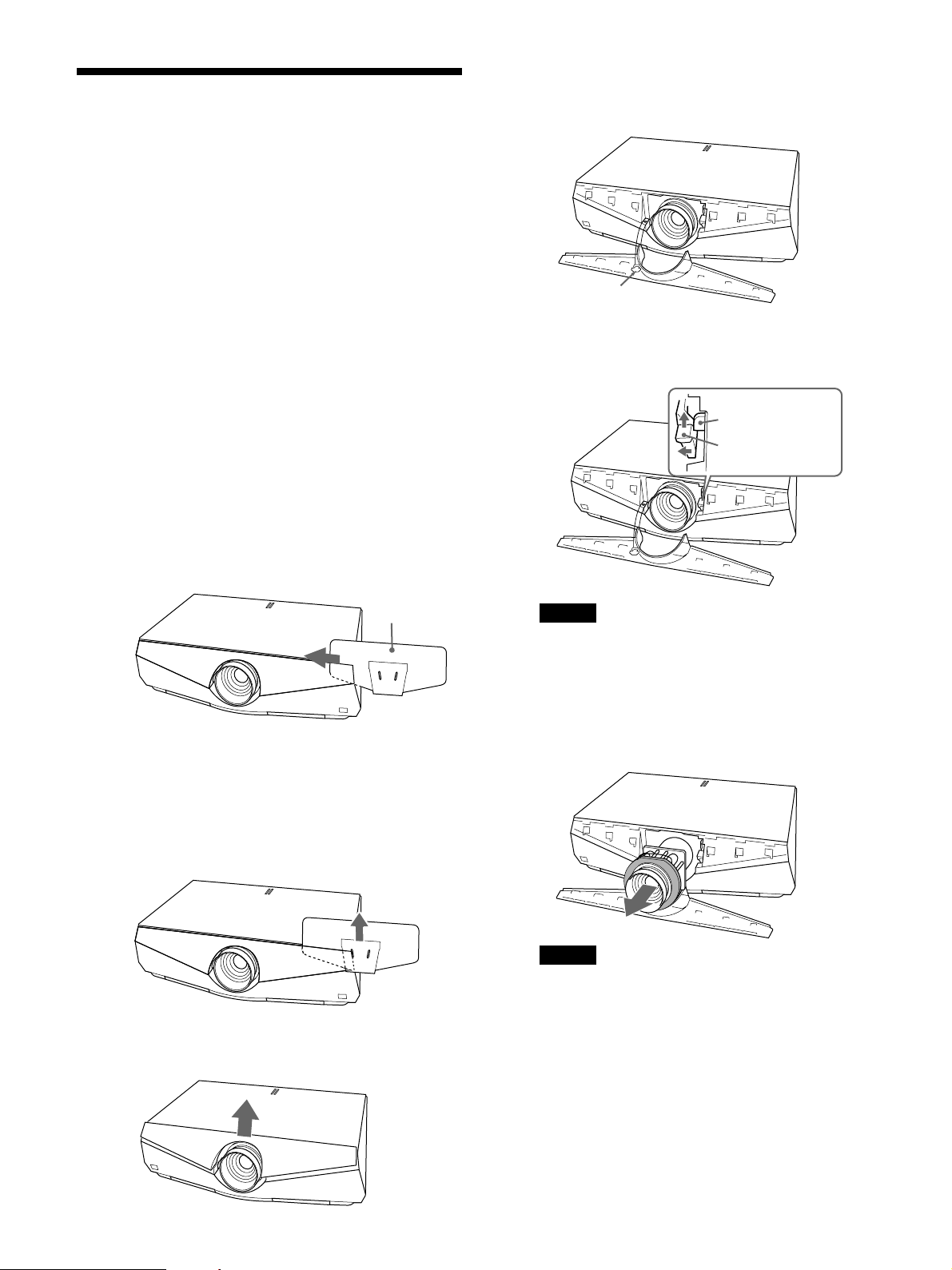
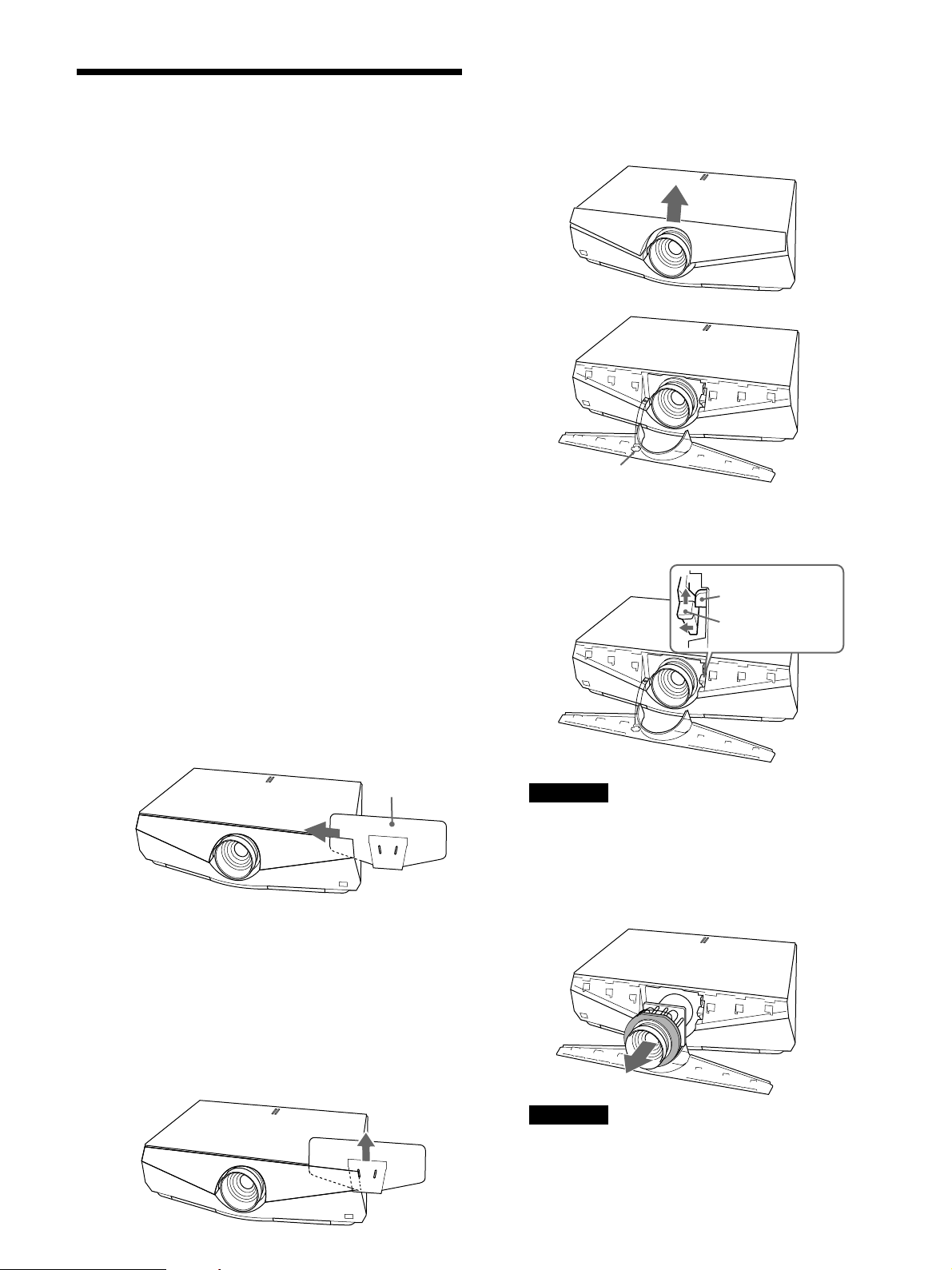
フロントパネ ル は 落下防止のため、本体とワイヤーでつな
がっています。
落下防止ワイヤー
4 レンズ 固 定レ バ ーをレン ズ 側 に寄せ、上に持ち上げる。
ロックツメ
1 電源を切り、電源コードを抜く。
2 フロントパ ネ ルを 次 の 手 順 で外す。
1 パネルリムーバーを図 のようにフロントパ ネ ル の 右 端 に 差
し込み、フロントパ ネ ル をはさみ込むように左へスライドさ
せる。
パネルリムーバー
2 パネルリムーバーでフロントパ ネ ル の 右 端 をしっかりはさ
み込み、パネルリムーバーが動かない位置(パネルリ
ムーバーの穴からフロントパ ネ ル の 端 が見える位置)ま
でスライドさせ たら、パ ネルリムーバーを 上 に 引 っ 張る。
フロントパネ ル の 右 側がはずれます。
レンズ固定レバー
ご注意
レンズ 固 定レバーは確実に上に持ち上げてください。レバー
が確実に上がっていないと、レンズ を 外 すことが できませ
ん。
5 レンズを 持 って 前 にまっすぐ 引き出 す 。
3 同様にフロントパ ネ ル の 左 半 分 を は ずし、フロントパ ネ ル を 上
に持ち上げてはずす。
8
ご注意
レンズを 取り出す際は両手を添えて取り出してください。
6 VPL-FE40L/FX40L/FX41L/FW41Lのレン ズ ホ ー ル カ
バーを外す。
Page 9
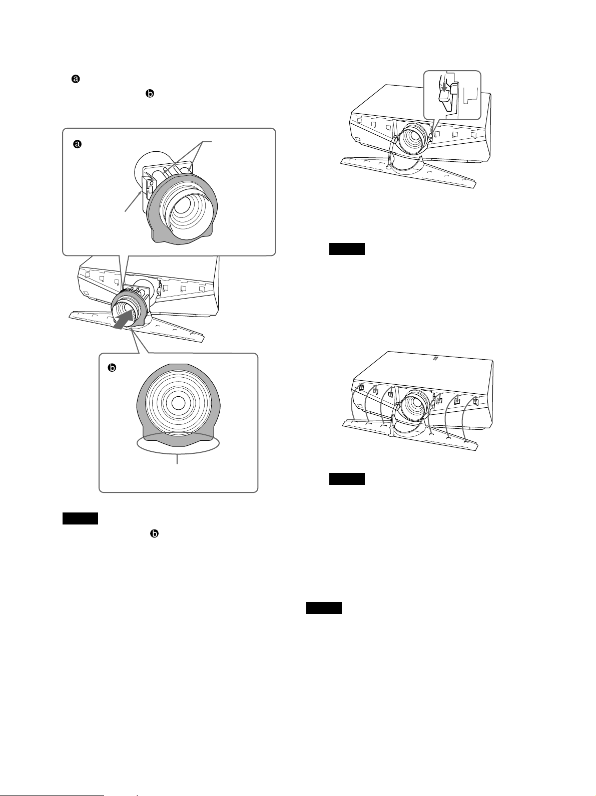
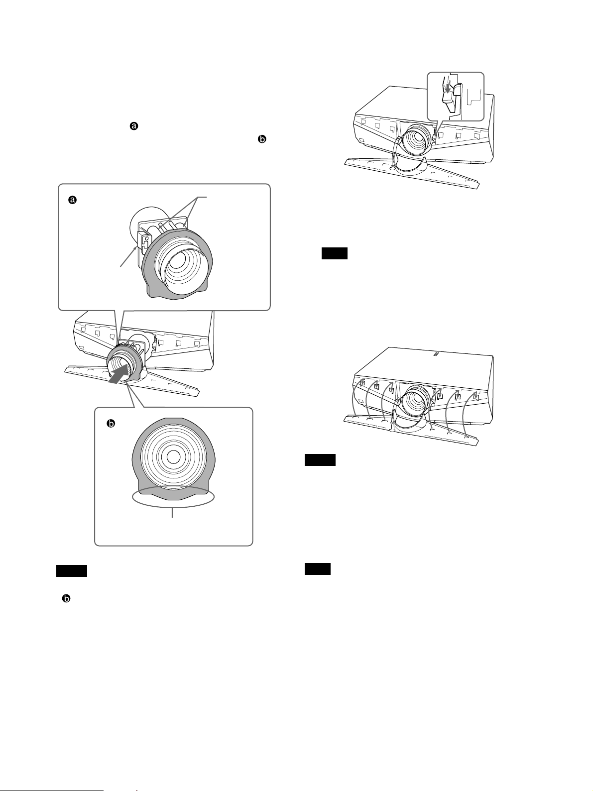
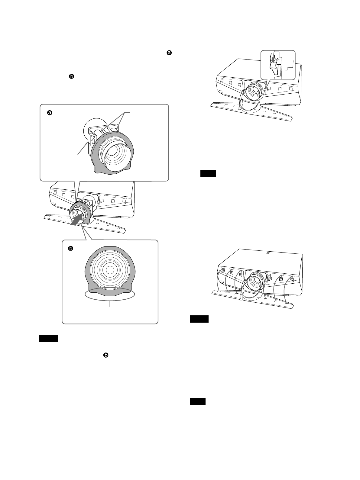
7 交換するレンズからレンズキャップ(2個)とレンズコネク
ターカバ ーを 外す。
のようにレンズのモーター部を 上 に 向け 、また、レンズ
図
の回りのクッションが図
認し、矢印の方向にまっすぐに差し込む。
レンズコネクター
カバー
のような位置になっていることを確
レンズの
モーター部
8 レンズ固定レバーを下まで確実に下げる。
レンズ固定レバーが下がらない場合は、レンズ が 奥まで 入 っ
ていない可能性があります。レン ズを 入れ直し、レバーを下
まで確実に下げてください。
ご注意
レンズ が 奥まで 入らな い 場 合 は 、レン ズを 少し 左 右 に 回しな
がら入 れ てください。
9 フロントパ ネ ル裏側のつめと下側の差し込み部を本体に差
し込み、カチッと音が するまでパネル 面を下に押し付けロッ
クする。
クッションのこの部分を下にする。
ご注意
• クッションの位置が図
で回して位置を合わせてください。そのとき、クッションが
レンズ の 溝 から外 れ な いようにご注意ください。
• レンズ交換の際は、レンズ の ガラス面がレバーなどにあた
らないよう、慎重に行ってください 。
のようになっていない場合は、手
ご注意
• 落下防止ワイヤーが飛び出さないようにご注意ください 。
• 左右のフロントパ ネ ル を は め 込んだあと、フロントパ ネル の
上部が本体より浮いていないか、またははみ出ていない
か確認してください 。
レンズ交換の際のご注意
レンズ 面 には 手をふ れないようにしてください。
ご注意
VPLL-1008は、VPL-FE40/FX40/FX41/FW41を床に 水平に置
いたときを 基 準 にし て+ 90°〜− 90°(レンズ 下 方 向 が プラスとし
て)の範囲内でご使用ください。
特約店様へ
VPLL-1008はリア投影(打ち込み角0°)用であり、水平・垂直方向と
もにスクリーン の 中 心とレン ズ の 中心が同じになるように設置する必要
があります。中心からずれた状態で設置すると、画が欠けますのでご
注意ください。
また、設置後は設置設定メニューのレンズコントロールを「切」に設定
することをお す す めします。
9
Page 10

English
Precautions
For kundene i Norge
Dette utstyret kan kobles til et ITstrømfordelingssystem.
On safety
• Check that the operating voltage of your unit is
identical with the voltage of your local power
supply. If voltage adaptation is required, consult with
qualified Sony personnel.
• Should any liquid or solid object fall into the cabinet,
unplug the unit and have it checked by qualified
Sony personnel before operating it further.
• Unplug the unit from the wall outlet if it is not to be
used for several days.
• To disconnect the cord, pull it out by the plug. Never
pull the cord itself.
• The wall outlet should be near the unit and easily
accessible.
• The unit is not disconnected from the AC power
source (mains) as long as it is connected to the wall
outlet, even if the unit itself has been turned off.
• Do not look into the lens while the lamp is on.
• Do not place your hand or objects near the
ventilation holes — the air coming out is hot.
• Avoid using an extension cord with a low voltage
limited since it may cause the short-circuit and
physical incidents.
• Do not catch your finger between the unit and
surface of the floor when moving the projector
installed on the floor.
• Be careful not to catch your finger in the cooling fan.
• Do not carry the projector with the cabinet on and
with its cover open.
Caution
Installation when setting the angle of projection to
more than ±20°
When you set the angle of projection to more than
±20°, place a metal tray measuring more than 60 cm ×
30 cm at a distance of 30 cm to 50 cm directly below
the exhaust vent. Also, take care that no material or
water drops fall into the opening of the exhaust vent.
On installation
• When the projector is mounted on the ceiling, the
Sony PSS-610 Projector Suspension Support must be
used for installation.
• Allow adequate air circulation to prevent internal
heat build-up. Do not place the unit on surfaces
(rugs, blankets, etc.) or near materials (curtains,
draperies) that may block the ventilation holes.
Leave space of more than 30 cm (11
between the wall and the projector. Be aware that
room heat rises to the ceiling; check that the
temperature near the installation location is not
excessive.
• Install the projector on the floor or ceiling. Any other
installation causes a mulfunction such as color
irregularity or shortening lamp life.
• Do not install the unit in a location near heat sources
such as radiators or air ducts, or in a place subject to
direct sunlight, excessive dust or humidity,
mechanical vibration or shock.
• To avoid moisture condensation, do not install the
unit in a location where the temperature may rise
rapidly.
• Be sure to secure the cabinet cover firmly when
installing to the ceiling firmly.
Warning
For customers who purchase this unit
If customers perform the installation described in this
manual, an accident may occur, causing serious
injury. Never install it by yourself. For installation, be
sure to consult with a Sony dealer.
For dealers
Pleae read this Installation Manual throughly for safe
installation.
7
/8 inches)
On illumination
CAUTION
Danger of explosion if battery is incorrectly replaced.
Replace only with the same or equivalent type
recommended by the manufacturer.
When you dispose of the battery, you must obey the
law in the relative area or country.
10
• To obtain the best picture, the front of the screen
should not be exposed to direct lighting or sunlight.
• Ceiling-mounted spot lighting is recommended. Use
a cover over fluorescent lamps to avoid lowering the
contrast ratio.
• Cover any windows that face the screen with opaque
draperies.
• It is desirable to install the projector in a room where
Page 11

floor and walls are not of light-reflecting material. If
the floor and walls are of reflecting material, it is
recommended that the carpet and wall paper be
changed to a dark color.
On preventing internal heat build-up
The projector is equipped with ventilation holes
(intake) at the bottom and ventilation holes (exhaust)
at the rear. Do not block or place anything near these
holes, or internal heat build-up may occur, causing
picture degradation or damage to the projector.
On cleaning
• To keep the cabinet looking new, periodically clean
it with a soft cloth. Stubborn stains may be removed
with a cloth lightly dampened with a mild detergent
solution. Never use strong solvents, such as thinner,
benzene, or abrasive cleansers, since these will
damage the cabinet.
• Avoid touching the lens. To remove dust on the lens,
use a soft dry cloth. Do not use a damp cloth,
detergent solution, or thinner.
• Clean the filter at regular intervals.
Overview
This manual describes how to install the Sony Data
Projector VPL-FE40/FE40L/FX40/FX40L/FX41/
FX41L/FW41/FW41L, how to replace the lens, and
installation diagrams. When you replace the lens, also
refer to the Operating Instructions.
On repacking
• Save the original shipping carton and packing
material; they will come in handy if you ever have to
ship your unit. For maximum protection, repack your
unit as it was originally packed at the factory.
11
Page 12
Replacing the Lens
You can install the following types of optional lenses
in the projector:
• VPLL-1008 Fixed Short Focus Lens
• VPLL-Z1014 Short Focus Zoom Lens
• VPLL-Z1024 Middle Focus Zoom Lens
• VPLL-Z1032 Long Focus Zoom Lens
Follow the steps below to replace each lens:
VPL-FE40/FX40/FX41/FW41 (equipped with
standard lens): steps 1 to 5 and, steps 7 to 9
VPL-FE40L/FX40L/FX41L/FW41L (lens optional):
steps 1 to 4, and steps 6 to 9
For details on replacing the lens, also refer to the
installation manual supplied with the lens.
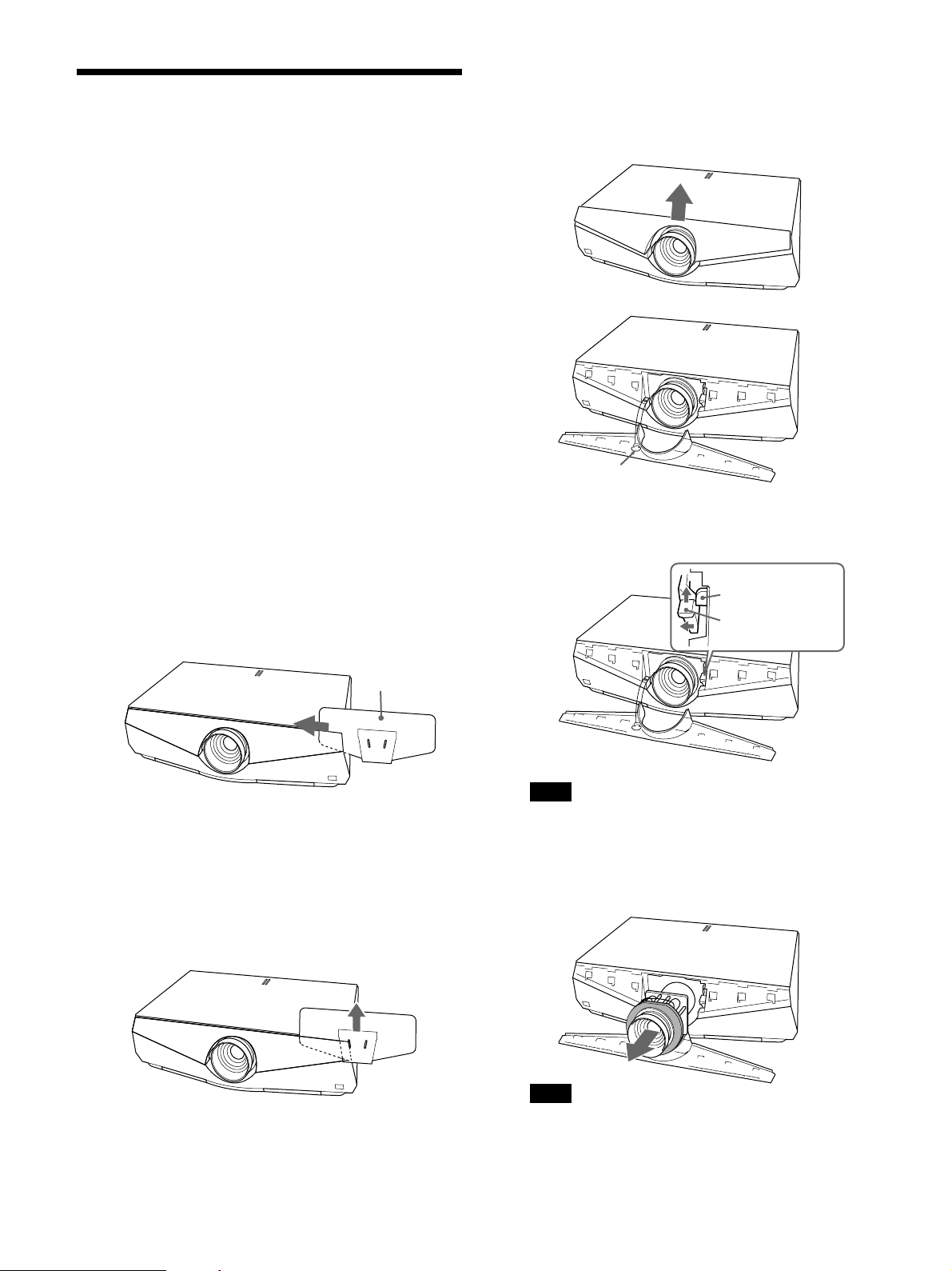
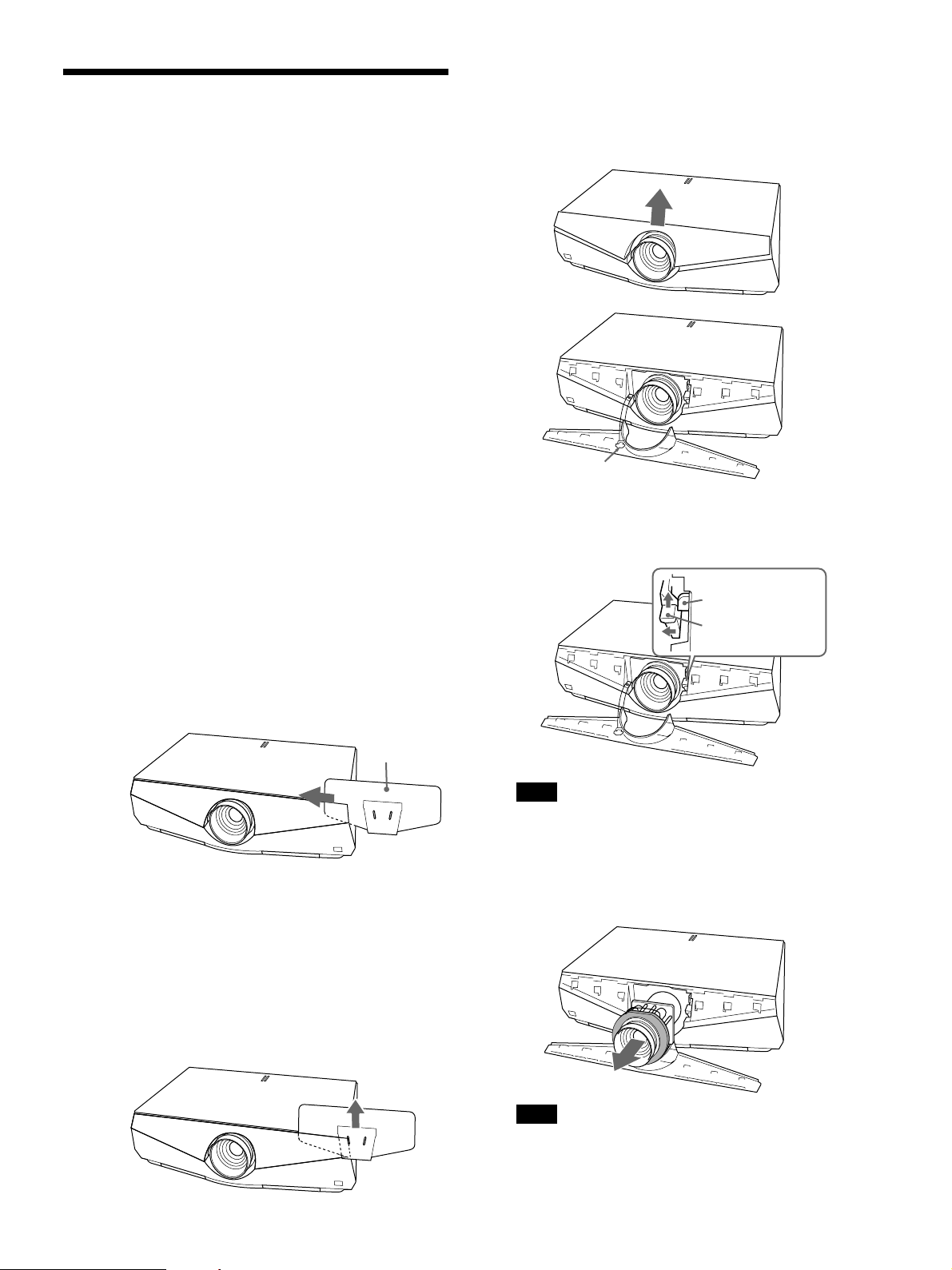
3 Remove the left half of the front panel in the same
step, and pick up the front panel.
The front panel is connected to the main unit with
a wire for safety.
1 Turn off the power and disconnect the power
cable.
2 Remove the front panel following the steps below.
1 Insert the panel remover from the right side of
the front panel as the illustration. Then slide
the panel remover toward left pinching the
front panel.
Panel remover
2 Pinch the right side of the front panel firmly
with the panel remover and slide it until it
stops (position in which the edge of the front
panel is seen from the hole of the panel
remover). Then pull up the panel remover.
The right side of the front panel is removed.
Safety wire
4 Move the lens fixing lever to the lens, then lift it
up.
Lock tab
Lens fixing lever
Note
Lift up the lens fixing lever correctly. Otherwise
you cannot remove the lens.
5 Withdraw the lens straight forward.
12
Note
Use both hands to withdraw the lens.
Page 13
6 Remove the lens hole cover of VPL-FE40L/
FX40L/FX41L/FW41L.
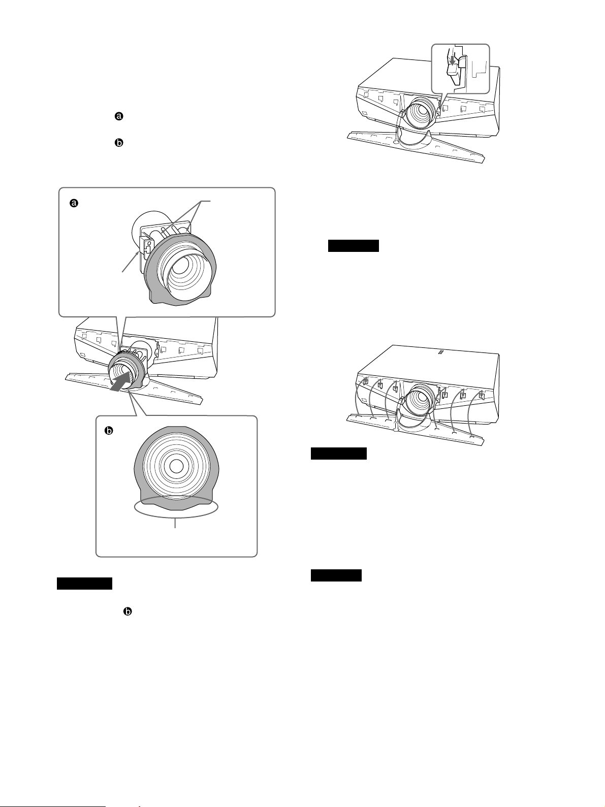
7 Remove two lens caps and the lens connector
cover from the replacment lens.
Adjust the lens so that the motor section faces up
as in illustration
around the lens is positioned as in illustration
Then insert the lens straight in the direction of the
arrow.
, and check that the cushion
8 Move the lens fixing lever down to the bottom
correctly.
.
Lens connector
cover
Face this side of the cushion down.
Motor section
If the lens fixing lever does not move down, the
lens may not be fully inserted. Insert it again and
move the lens fixing lever down to the bottom
correctly.
Note
If the lens does not go in fully, turn the lens
slightly right and left slightly.
9 Insert the tab on the rear of the front panel and the
plug-in part into the main unit, then hold down the
panel so it locks with a click.
Notes
• Take care not to allow the safety wire to protrude.
• After fitting the left and right front panels, check
that the top of the front panel does not lift up or
protrude from the main unit.
Note on changing lenses
Do not touch the surface of the lens.
Notes
• If the cushion is not positioned as in illustration
, rotate it by hand. In this case, take care that
the cushion does not come off the groove of the
lens.
• Change the lens carefully so as not to damage the
lens glass with the lever or other parts.
Note
When you use the VPLL-1008, do so in the range
between +90° and –90° (when the lower parts of the
lens is a plus) on the basis of installing the VPL-FE40/
FX40/FX41/FW41 horizontally on the floor.
For Dealer
The VPLL-1008 is the lens for rear projection (optical
axis angle: 0 degree). When using the VPLL-1008,
you should install the projector with the center of the
lens aligned with the center of the screen in the
horizontal/vertical direction. If you do not do so, a
portion of the picture may be invisible.
Also, after installing the lens, we recommend to set
“Lens Control” in the Installation menu to “Off”.
13
Page 14

Français
Précautions
Lorsque vous mettez la batterie au rebut, vous devez
respecter la législation en vigueur dans le pays ou la
région où vous vous trouvez.
Sécurité
• Vérifiez si la tension de service de votre appareil est
identique à la tension secteur locale. Si une
adaptation de la tension s’avère nécessaire,
consultez votre revendeur Sony ou un personnel
qualifié.
• Si des liquides ou des solides pénètrent dans le
châssis, débranchez l’appareil et faites-le vérifier par
un personnel Sony qualifié avant de le remettre en
service.
• Débranchez l’appareil de la prise murale si vous
prévoyez de ne pas l’utiliser pendant plusieurs jours.
• Pour débrancher le cordon, saisissez-le par la fiche.
Ne tirez jamais sur le cordon proprement dit.
• La prise d’alimentation doit se trouver à proximité
de l’appareil et être aisément accessible.
• Cet appareil n’est pas déconnecté de la source
d’alimentation (secteur) aussi longtemps qu’il reste
branché sur la prise murale, même si l’appareil
proprement dit a été mis hors tension.
• Ne regardez pas dans l’objectif lorsque la lampe est
allumée.
• Ne placez pas les mains ou des objets à proximité
des orifices de ventilation — l’air expulsé est chaud.
• Evitez d’utiliser une rallonge affichant une tension
basse limitée car cela pourrait provoquer un courtcircuit et des accidents physiques.
• Ne coincez pas vos doigts entre l’appareil et le sol
lorsque vous déplacez le projecteur installé au sol.
• Veillez à ne pas vous coincer les doigts dans le
ventilateur.
• Ne transportez pas le projecteur par le châssis
installé et avec le couvercle ouvert.
Attention
Installation lorsque vous réglez un angle de
projection supérieur à ±20°
Lorsque l’angle de projection est supérieur à ±20°,
placez un plateau métallique mesurant plus de
60 cm × 30 cm à une distance allant de 30 cm à 50 cm
directement sous l’orifice de ventilation. En outre,
veillez à ce qu’aucune substance ou goutte d’eau ne
tombe dans l’ouverture de l’orifice de ventilation.
Installation
• Si vous installez le projecteur au plafond, vous
devez utiliser le support de suspension pour
projecteur Sony PSS-610.
• Assurez une circulation d’air adéquate afin d’éviter
toute surchauffe interne. Ne placez pas l’appareil sur
des surfaces textiles (tapis, couvertures, etc.) ni à
proximité de tissus (rideaux, draperies) qui risquent
d’obstruer les orifices de ventilation. Laissez un
espace d’au moins 30 cm (11
mur et le projecteur. N’oubliez pas que la chaleur
dans une pièce monte; vérifiez donc si la
température au niveau du lieu d’installation n’est
pas excessive.
• Installez le projecteur au sol ou au plafond. Toute
autre installation provoquera un dysfonctionnement
(irrégularité des couleurs ou réduction de la durée de
vie de la lampe).
• N’installez pas l’appareil à proximité de sources de
chaleur telles que des radiateurs ou des conduits
d’air chaud et ne l’exposez pas au rayonnement
direct du soleil, à de la poussière ou à de l’humidité
en excès, ni à des vibrations mécaniques ou à des
chocs.
• Pour éviter la condensation d’humidité, n’installez
pas l’appareil là où la température risque
d’augmenter rapidement.
• Veillez à fixer le couvercle du châssis
convenablement lorsque vous l’installez au plafond.
Avertissement
A l’attention des clients ayant fait l’acquisition de
cet appareil
Si vous essayez de procéder vous-même à
l’installation décrite dans ce manuel, vous risquez
d’être victime d’un accident provoquant de graves
blessures. Ne procédez jamais vous-même à
l’installation. Pour l’installation, veillez à consultez un
revendeur Sony.
A l’attention des revendeurs
Lisez attentivement ce manuel d’installation afin de
procéder à l’installation en toute sécurité.
7
/8 pouces) entre le
ATTENTION
Il y a danger d’explosion s’il y a remplacement
incorrect de la batterie. Remplacer uniquement avec
une batterie du même type ou d’un type équivalent
recommandé par le constructeur.
14
Eclairage
• Pour obtenir la meilleure qualité d’image possible,
l’avant de l’écran ne doit pas être directement
exposé à la source d’éclairage ni au rayonnement
Page 15

solaire.
• Nous préconisons un éclairage au moyen de spots
fixés au plafond. Placez un écran sur les lampes
fluorescentes de façon à éviter une altération du
niveau de contraste.
• Occultez les fenêtres qui font face à l’écran au
moyen de draperies opaques.
• Il est préférable d’installer le projecteur dans une
pièce où le sol et les murs ne sont pas revêtus d’un
matériau réfléchissant la lumière. Si le sol et les
murs réfléchissent la lumière, nous vous conseillons
de remplacer le revêtement du sol et des murs par
une couleur sombre.
Comment éviter l’accumulation de
chaleur à l’intérieur du projecteur
Le projecteur est équipé d’orifices de ventilation
(prise d’air) sur le dessous et d’orifices de ventilation
(sortie d’air) à l’arrière. N’obstruez pas et ne placez
rien à proximité de ces orifices, sinon vous risquez de
provoquer une surchauffe interne, entraînant une
dégradation de l’image ou une détérioration du
projecteur.
Aperçu
Le présent manuel décrit comment installer les
vidéoprojecteurs Sony VPL-FE40/FE40L/FX40/
FX40L/FX41/FX41L/FW41/FW41L, comment
remplacer l’objectif et comporte des schémas
d’installation. Lors du remplacement de l’objectif,
reportez-vous également au mode d’emploi.
Entretien
• Pour conserver au châssis l’éclat du neuf, nettoyezle régulièrement à l’aide d’un chiffon doux. Les
taches tenaces s’éliminent en frottant avec un
chiffon doux légèrement imprégné d’une solution
détergente douce. N’utilisez en aucun cas des
solvants puissants tels que du diluant ou du benzène
ni de nettoyants abrasifs qui risqueraient d’altérer le
fini du châssis.
• Ne touchez pas l’objectif. Pour éliminer la poussière
de l’objectif, utilisez un chiffon doux et sec.
N’utilisez pas de chiffon humide, de solution
détergente ni de diluant.
• Nettoyez l’objectif à intervalles réguliers.
Remballage
• Conservez le carton d’emballage et les matériaux de
conditionnement, car ils constituent une protection
idéale en vue du transport de l’appareil. Pour une
protection maximale, remballez votre appareil
comme il a été emballé à l’origine en usine.
15
Page 16
Remplacement de
l’objectif
Vous pouvez installer les types d’objectifs en option
suivants sur le projecteur :
• objectif à courte focale fixe VPLL-1008;
• objectif à courte focale VPLL-Z1014;
• objectif à focale moyenne VPLL-Z1024 ;
• objectif à longue focale VPLL-Z1032.
Pour remplacer l’objectif, procédez comme suit :
Pour le VPL-FE40/FX40/FX41/FW41 (doté d’un
objectif standard) : exécutez les opérations des
étapes 1 à 5 et 7 à 9.
Pour le VPL-FE40L/FX40L/FX41L
option) : exécutez les opérations des étapes 1 à 4 et 6 à 9.
/FW41L
(objectif en
3 Effectuez la même opération sur le côté gauche du
panneau avant, puis soulevez-le.
Le panneau avant est raccordé à l’appareil
principal par un cordon pour plus de sécurité.
Pour plus d’informations sur le remplacement de l’objectif,
reportez-vous également au manuel d’installation fourni
avec l’objectif.
1 Mettez le projecteur hors tension et débranchez le
cordon d’alimentation.
2 Procédez comme suit pour retirer le panneau
avant.
1 Insérez l’accessoire destiné au retrait du
panneau sur le côté droit du panneau avant,
comme illustré. Faites ensuite glisser
l’accessoire destiné au retrait du panneau vers
la gauche en pinçant le panneau avant.
Accessoire destiné au
retrait du panneau
2 Pincez fermement le côté droit du panneau
avant avec l’accessoire destiné au retrait du
panneau et faites-le glisser jusqu’à ce qu’il ne
bouge plus (position où le bord du panneau
avant est visible au travers de l’orifice de
l’accessoire destiné au retrait du panneau).
Soulevez ensuite l’accessoire destiné au retrait
du panneau.
La partie droite du panneau avant est détachée.
Cordon de sécurité
4 Déplacez le levier de fixation de l’objectif vers
l’objectif, puis soulevez-le.
Taquet de
verrouillage
Levier de fixation
de l’objectif
Remarque
Soulevez correctement le levier de fixation de
l’objectif, sinon vous ne pouvez pas retirer
l’objectif.
5 Retirez l’objectif en le tirant vers l’avant.
16
Remarque
Utilisez vos deux mains pour retirer l’objectif.
6 Retirez le couvercle de l’emplacement de
l’objectif du VPL-FE40L/FX40L/FX41L/FW41L.
Page 17
7 Retirez les deux capuchons d’objectif ainsi que le
couvercle du connecteur de l’objectif de l’objectif
de rechange.
Réglez l’objectif de sorte que le bloc moteur soit
tourné vers le haut comme indiqué sur
l’illustration
autour de l’objectif est positionné comme sur
l’illustration
Ensuite, insérez l’objectif dans le sens de la
flèche.
Couvercle du
connecteur de
l’objectif
, puis vérifiez que le coussin situé
.
Bloc moteur
Si vous ne pouvez pas baisser le levier de fixation
de l’objectif, l’objectif risque de ne pas être inséré
complètement. Insérez-le de nouveau et baissez
correctement le levier de fixation de l’objectif
jusqu’en bas.
Remarque
Si l’objectif n’est pas inséré complètement, tournezle légèrement vers la droite, puis vers la gauche.
9 Insérez l’attache à l’arrière du panneau avant et la
partie enfichable dans l’appareil principal, puis
maintenez le panneau enfoncé jusqu’au déclic de
verrouillage.
Positionnez ce côté du coussin
vers le bas.
Remarques
• Si le coussin n’est pas positionné comme sur
l’illustration
, faites-le pivoter manuellement.
Dans ce cas, veillez à ce que le coussin ne se
détache pas de la rainure de l’objectif.
• Changez l’objectif avec précaution de façon à ne
pas endommager le verre de l’objectif avec le
levier ou d’autres éléments.
8 Baissez correctement le levier de fixation de
l’objectif jusqu’en bas.
Remarques
• Veillez à ce que le cordon de sécurité ne dépasse
pas de l’appareil.
• Une fois les panneaux avants gauche et droit fixés,
vérifiez que le haut du panneau avant ne se soulève
pas ou ne dépasse pas de l’appareil principal.
Remarque sur le changement des objectifs
Ne touchez pas la surface de l’objectif.
Remarque
Lorsque vous utilisez l’objectif VPLL-1008, utilisez
un réglage compris entre + 90 ° et – 90 ° (lorsque la
direction inférieure de l’objectif est un plus), en se
basant sur une installation horizontale du VPL-FE40/
FX40/FX41/FW41 sur le sol.
17
Page 18

A l’attention des revendeurs
Le VPLL-1008 est l’objectif pour la projection arrière
(angle de l’axe optique : 0 degré). Lorsque vous
utilisez l’objectif VPLL-1008, vous devez aligner le
centre de l’objectif du projecteur sur le centre de
l’écran horizontalement et verticalement. Si vous
n’effectuez pas cette installation, il est possible qu’une
partie de l’image ne soit pas visible.
Après l’installation de l’objectif, nous vous
recommandons aussi de régler « Cde objectif » sur
« Off » dans le menu Installation.
18
Page 19

Español
Precauciones
Seguridad
por otra del mismo tipo o de un tipo equivalente
recomendado por el fabricante.
Cuando deseche la batería, debe cumplir con las leyes
de la zona o del país.
• Asegúrese de que la tensión de funcionamiento de la
unidad coincide con la del suministro eléctrico local.
Si es necesario adaptar la tensión, consulte con
personal especializado de Sony.
• Si se introduce algún objeto sólido o líquido en la
unidad, desenchúfela y haga que sea examinada por
personal especializado de Sony antes de volver a
utilizarla.
• Desenchufe la unidad de la toma de pared si no va a
utilizarla durante varios días.
• Para desconectar el cable, tire del enchufe, nunca
del propio cable.
• La toma de pared debe estar situada cerca de la
unidad y ser de fácil acceso.
• La unidad no estará desconectada de la fuente de
alimentación de CA (toma de corriente) mientras
esté conectada a la toma de red, aunque la haya
apagado.
• No mire al objetivo mientras la lámpara esté
encendida.
• No acerque la mano ni objetos a los orificios de
ventilación, ya que el aire que sale es caliente.
• Evite el uso de cables prolongadores de baja tensión
limitada, ya que pueden producirse cortocircuitos y
daños físicos.
• Tenga cuidado de no pillarse los dedos entre la
unidad y el suelo cuando mueva el proyector
instalado en el suelo.
• Tenga cuidado de no pillarse los dedos con el
ventilador de enfriamiento.
• No transporte el proyector con la cubierta puesta ni
abierta.
Precaución
Instalación cuando el ajuste del ángulo de
proyección es superior a ±20°
Cuando ajuste el ángulo de proyección a más de ±20°,
coloque una bandeja metálica de más de 60 × 30 cm a
una distancia de 30 a 50 cm directamente bajo el
orificio de salida de aire. Asimismo, procure que no se
introduzca ningún material ni líquido por el orificio de
salida de aire.
Instalación
• Si instala el proyector en el techo, debe emplearse el
soporte de suspensión para proyector PSS-610 de
Sony.
• Con el fin de evitar el recalentamiento interno de la
unidad, permita que ésta reciba una ventilación
adecuada. No sitúe la unidad sobre superficies
(mantas, alfombras, etc.) ni cerca de materiales
(cortinas, tapices) que puedan bloquear los orificios
de ventilación. Deje un espacio superior a 30 cm (11
7
/8 pulgadas) entre la pared y el proyector. Tenga en
cuenta que el calor del ambiente se eleva hacia el
techo (compruebe que la temperatura en el lugar de
instalación no sea excesiva).
• Instale el proyector en el suelo o en el techo.
Cualquier otro tipo de instalación provocará fallos
de funcionamiento, como irregularidades del color o
la reducción de la vida útil de la lámpara.
• No instale la unidad en lugares próximos a fuentes
térmicas, como radiadores o conductos de aire
caliente, ni en lugares expuestos a la luz solar
directa, polvo excesivo o humedad, ni vibraciones o
golpes mecánicos.
• Para evitar la condensación de humedad, no instale
la unidad en lugares donde la temperatura pueda
aumentar rápidamente.
• Asegúrese de fijar firmemente la cubierta al realizar
la instalación en el techo.
Advertencia
Para clientes que hayan adquirido esta unidad
Si los clientes llevan a cabo la instalación que se
describe en este manual, podría producirse un
accidente y causar lesiones graves. No lo instale
nunca usted mismo. Para proceder a la instalación,
asegúrese de consultar con un proveedor Sony.
Para los proveedores
Lea atentamente este manual de instalación para
realizar una instalación segura.
Iluminación
PRECAUCIÓN
Peligro de explosión si se sustituye la batería por una
del tipo incorrecto. Reemplace la batería solamente
• Para obtener la mejor calidad de imagen posible, no
exponga la parte frontal de la pantalla a iluminación
o luz solar directas.
19
Page 20

• Se recomienda instalar una lámpara proyectora en el
techo. Cubra las lámparas fluorescentes para evitar
la disminución de la relación de contraste.
• Cubra con telas opacas las ventanas que estén
orientadas hacia la pantalla.
• Es preferible instalar el proyector en una sala cuyo
suelo y paredes no se compongan de materiales que
reflejen la luz. Si el suelo y las paredes se componen
de dicho tipo de materiales, se recomienda cambiar
el color de la alfombra y del papel pintado de la
pared por otro oscuro.
Prevención del recalentamiento interno
El proyector está equipado con orificios de ventilación
(aspiración) en la parte inferior y orificios de
ventilación (exhaustación) en la parte posterior. No
bloquee estos orificios ni coloque objetos cerca de los
mismos, ya que podría producirse un recalentamiento
interno, causando deterioro de la imagen o daños en el
proyector.
Introducción
En este manual se describen los procedimientos para
instalar el proyector de datos de Sony, modelos VPLFE40/FE40L/FX40/FX40L/FX41/FX41L/FW41/
FW41L, y sustituir el objetivo, y se ofrecen diagramas
de instalación. Al sustituir el objetivo o cambiar su
posición, consulte las instrucciones de uso.
Limpieza
• Para mantener el exterior de la unidad nuevo,
límpielo periódicamente con un paño suave. Para
eliminar las manchas persistentes, utilice un paño
ligeramente humedecido con una solución
detergente poco concentrada. No emplee nunca
disolventes concentrados, como diluyentes, bencina
o productos de limpieza abrasivos, ya que pueden
dañar el acabado.
• Evite tocar el objetivo. Para eliminar el polvo de
éste, emplee un paño seco y suave. No utilice un
paño húmedo, soluciones detergentes ni diluyentes.
• Limpie el filtro con regularidad.
Embalaje
• Conserve la caja original de embalaje, ya que le
resultará útil cuando vaya a transportar la unidad.
Para obtener la máxima protección posible, embale
la unidad como la recibió de fábrica.
20
Page 21
Sustitución del objetivo
Es posible instalar los siguientes tipos de objetivos
opcionales en el proyector:
• Objetivo fijo de enfoque corto para VPLL-1008
• Objetivo zoom de enfoque corto VPLL-Z1014
• Objetivo zoom de enfoque medio para VPLL-Z1024
• Objetivo zoom de enfoque largo para VPLL-Z1032
Siga los pasos indicados a continuación para sustituir
el objetivo:
VPL-FE40/FX40/FX41/FW41 (equipado con objetivo
estándar): pasos del 1 al 5 y del 7 al 9
VPL-FE40L/FX40L/FX41L/FW41L (objetivo
opcional): pasos del 1 al 4 y del 6 al 9
Para obtener información más detallada sobre cómo
sustituir el objetivo, también puede consultar el manual de
instalación suministrado con éste.
3 Extraiga la mitad izquierda del panel frontal en el
mismo paso y sujételo.
El panel frontal está conectado a la unidad
principal mediante un cable de seguridad.
Cable de seguridad
1 Turn off the power and disconnect the power
cable.
2 Realice los pasos que se describen a continuación
para extraer el panel frontal.
1 Introduzca la placa para la extracción del
panel desde el lado derecho del panel frontal,
como se muestra en la ilustración y deslícela
hacia la izquierda de modo que oprima el
panel frontal.
Placa para la
extracción del panel
2 Oprima con firmeza el lado derecho del panel
frontal con la placa para la extracción del
panel y deslícela hasta que se detenga (en la
posición donde el extremo del panel frontal se
ve desde el orificio de la placa de extracción
del panel). A continuación, tire de la placa
para la extracción del panel.
La parte derecha del panel frontal se extraerá.
4 Deslice la palanca de fijación del objetivo hacia
éste y, a continuación, levántela.
Pestaña de bloqueo
Palanca de fijación
del objetivo
Nota
Levante la palanca de fijación del objetivo
correctamente. De lo contrario, no podrá extraer el
objetivo.
5 Extraiga el objetivo en línea recta.
Nota
Utilice ambas manos para extraer el objetivo.
6 Retire la cubierta del orificio del objetivo del
modelo VPL-FE40L/FX40L/FX41L/FW41L.
21
Page 22
7 Retire las dos tapas del objetivo y la cubierta del
conector de éste del objetivo que desea instalar.
Ajuste el objetivo de manera que la sección motriz
quede hacia arriba, como muestra la ilustración
y compruebe que el cojinete situado alrededor del
objetivo quede colocado como muestra la
ilustración
A continuación, introduzca el objetivo en línea
recta en la dirección de la flecha.
Cubierta del
conector del
objetivo
.
Sección motriz
8 Desplace la palanca de fijación del objetivo hacia
abajo correctamente.
,
Si no consigue desplazar la palanca de fijación del
objetivo hacia abajo, es posible que el objetivo no
se haya introducido correctamente. Introdúzcalo
de nuevo y desplace la palanca de fijación del
objetivo hacia abajo correctamente.
Nota
Si no es posible introducir el objetivo
completamente, gírelo levemente hacia la derecha
y hacia la izquierda.
Oriente este lado del cojinete
hacia abajo.
Notas
• Si el cojinete no queda en la posición que
muestra la ilustración
, gírelo manualmente.
En tal caso, procure que el cojinete no
sobresalga de la ranura del objetivo.
• Reemplace el objetivo con cuidado de no dañar
el cristal del objetivo con la palanca ni ninguna
otra pieza.
9 Introduzca la pestaña de la parte posterior del
panel frontal y la pieza de conexión en la unidad
principal y, a continuación, deslice el panel hacia
abajo de manera que encaje en su sitio.
Notas
• Compruebe que el cable de seguridad no sobresalga.
• Una vez colocados los paneles frontales izquierdo y
derecho, compruebe que la parte superior del panel
frontal no se levanta ni sobresale de la unidad
principal.
Nota acerca de la sustitución del objetivo
Procure no tocar la superficie del objetivo.
Nota
Utilice la unidad VPLL-1008 en un rango de entre +
90° y – 90° (cuando la dirección más baja del objetivo
es de signo positivo) en caso de instalar la unidad
VPL-FE40/FX40/FX41/FW41 horizontalmente en el
suelo.
22
Page 23

Para los proveedores
VPLL-1008 es un objetivo para la proyección
posterior (ángulo axial óptico: 0 grados). Al utilizar el
VPLL-1008, debe instalar el proyector de modo que la
parte central del objetivo quede alineada con el centro
de la pantalla en dirección horizontal y vertical. De lo
contrario, es posible que no se visualice alguna parte
de la imagen.
Además, después de la instalación del objetivo, se
recomienda ajustar “Control objetivo” en “No” el
menú Instalación.
23
Page 24

Deutsch
Sicherheitsmaßnahmen
Sicherheit
• Achten Sie darauf, dass die Betriebsspannung des
Geräts der lokalen Stromversorgung entspricht.
Wenn die Betriebsspannung angepasst werden muss,
wenden Sie sich bitte an qualifiziertes Fachpersonal
von Sony.
• Sollten Fremdkörper oder Flüssigkeiten in das Gerät
gelangen, trennen Sie es von der Netzsteckdose.
Lassen Sie das Gerät von qualifiziertem
Fachpersonal von Sony überprüfen, bevor Sie es
wieder benutzen.
• Wollen Sie das Gerät einige Tage nicht benutzen,
ziehen Sie den Netzstecker aus der Steckdose.
• Ziehen Sie zum Lösen des Netzsteckers immer am
Stecker, niemals am Kabel.
• Die Netzsteckdose sollte sich in der Nähe des Geräts
befinden und leicht zugänglich sein.
• Das Gerät bleibt auch in ausgeschaltetem Zustand
mit dem Stromnetz verbunden, solange das
Netzkabel mit der Netzsteckdose verbunden ist.
• Schauen Sie nicht in das Objektiv, während die
Birne eingeschaltet ist.
• Stellen Sie keine Gegenstände in die Nähe der
Lüftungsöffnungen und halten Sie auch Ihre Hände
davon fern — die ausströmende Luft ist heiß!
• Verwenden Sie kein Verlängerungskabel, das nur für
geringe Spannungen ausgelegt ist. Ein solches Kabel
könnte zu Kurzschlüssen und sonstigen Unfällen
führen.
• Wenn Sie einen am Boden installierten Projektor
bewegen, achten Sie darauf, die Hände nicht
zwischen Fußboden und Projektor einzuklemmen.
• Greifen Sie auf keinen Fall in den Ventilator.
• Tragen Sie einen in einen Ständer eingebauten
Projektor nicht mit geöffneter Abdeckung.
VORSICHT
Explosionsgefahr bei Verwendung falscher Batterien.
Batterien nur durch den vom Hersteller empfohlenen
oder einen gleichwertigen Typ ersetzen.
Wenn Sie die Batterie entsorgen, müssen Sie die
Gesetze der jeweiligen Region und des jeweiligen
Landes befolgen.
Aufstellung
• Mithilfe der Projektoraufhängung PSS-610 von Sony
können Sie den Projektor an der Decke installieren.
• Achten Sie auf ausreichende Luftzufuhr, damit sich
im Gerät kein Wärmestau bildet. Stellen Sie das
Gerät nicht auf Oberflächen wie Teppichen oder
Decken oder in der Nähe von Materialien wie
Gardinen und Wandbehängen auf, die die
Lüftungsöffnungen blockieren könnten. Achten Sie
auf einen Mindestabstand von 30 cm zwischen der
Wand und dem Projektor. Denken Sie bei
Deckeninstallationen daran, dass Wärme zur Decke
aufsteigt. Achten Sie darauf, dass die Temperatur am
Installationsort nicht zu hoch ist.
• Installieren Sie den Projektor am Boden oder an der
Decke. Bei Installation in einer anderen Position
kann es zu Fehlfunktionen wie Farbstörungen
kommen und die Lebensdauer der Birne ist
möglicherweise verkürzt.
• Stellen Sie das Gerät nicht in der Nähe von
Wärmequellen wie Heizkörpern oder
Warmluftauslässen oder an Orten auf, an denen es
direktem Sonnenlicht, außergewöhnlich viel Staub
oder Feuchtigkeit, mechanischen Vibrationen oder
Stößen ausgesetzt ist.
• Installieren Sie das Gerät nicht an einem Ort, an dem
die Temperatur sehr schnell ansteigen und zu
Feuchtigkeitskondensation führen könnte.
• Achten Sie darauf, die Abdeckung sicher zu
befestigen, wenn Sie das Gerät an der Decke
installieren.
Achtung
Installation bei einem Projektionswinkel von über
±20°
Wenn Sie einen Projektionswinkel von über ±20°
einstellen, platzieren Sie eine Metallplatte von mehr
als 60 cm × 30 cm im Abstand von 30 cm bis 50 cm
direkt unter der Auslassöffnung. Achten Sie zudem
darauf, dass keine Fremdkörper oder Flüssigkeiten in
die Auslassöffnung gelangen.
24
Achtung
Für Kunden, die dieses Gerät erwerben
Wenn Kunden die in dieser Anleitung beschriebene
Installation ausführen, kann es zu einem Unfall und
dabei zu schweren Verletzungen kommen. Installieren
Sie das Gerät auf keinen Fall selbst. Wenden Sie sich
für die Installation unbedingt an einen Sony-Händler.
Für Händler
Bitte lesen Sie diese Installationsanleitung für eine
sichere Installation sorgfältig durch.
Page 25

Beleuchtung
• Um eine optimale Bildqualität zu erzielen, achten Sie
darauf, dass kein Licht direkt auf die Vorderseite des
Projektionsschirms fällt.
• Empfohlen wird eine Spotbeleuchtung an der Decke.
Leuchtstoffröhren sollten Sie abdecken, um eine
Verminderung des Kontrasts zu verhindern.
• Verhängen Sie Fenster, die dem Projektionsschirm
direkt gegenüber liegen.
• Sie sollten den Projektor in einem Raum installieren,
in dem Boden und Wände mit einem Material
verkleidet sind, das kein Licht reflektiert. Ist dies
nicht möglich, sollten Sie für Bodenbelag und
Wandverkleidung ein dunkles Material wählen.
Vermeiden eines internen Hitzestaus
Der Projektor ist an der Unterseite mit
Ansaugöffnungen und an der Rückseite mit
Auslassöffnungen ausgestattet. Blockieren Sie diese
Öffnungen nicht und stellen Sie keine Gegenstände in
die Nähe der Öffnungen. Andernfalls kann es zu
einem Wärmestau kommen, der zu einer Verringerung
der Bildqualität oder Schäden am Projektor führen
kann.
Übersicht
In dieser Anleitung wird beschrieben, wie Sie den
Datenprojektor VPL-FE40/FE40L/FX40/FX40L/
FX41/FX41L/FW41/FW41L von Sony installieren
und das Objektiv austauschen. Außerdem sind
Installationsdiagramme abgebildet. Schlagen Sie bitte
auch in der Bedienungsanleitung nach, wenn Sie das
Objektiv austauschen wollen.
Reinigung
• Damit das Gehäuse immer wie neu aussieht, reinigen
Sie es regelmäßig mit einem weichen Tuch.
Hartnäckige Verschmutzungen können Sie mit
einem Tuch entfernen, das Sie leicht mit einer
milden Reinigungslösung angefeuchtet haben.
Verwenden Sie keine starken Lösungsmittel wie
Verdünner oder Benzin und keine Scheuermittel, da
diese die Gehäuseoberfläche angreifen.
• Berühren Sie das Objektiv nicht. Mit einem weichen,
trockenen Tuch können Sie Staub vom Objektiv
entfernen. Feuchten Sie das Tuch nicht an und
benutzen Sie weder eine Reinigungsflüssigkeit noch
Verdünner.
• Reinigen Sie den Filter in regelmäßigen Abständen.
Verpacken
• Bewahren Sie Originalkarton und
Verpackungsmaterialien gut auf für den Fall, dass
Sie das Gerät später einmal transportieren müssen.
Am besten geschützt ist das Gerät beim Transport,
wenn Sie es wieder so verpacken, wie es geliefert
wurde.
25
Page 26

Austauschen des
Objektivs
Die folgenden gesondert erhältlichen Objektivtypen
können im Projektor installiert werden:
• Objektiv VPLL-1008 mit feststehender
Kurzbrennweite
• Zoomobjektiv VPLL-Z1014 mit kurzer Brennweite
• Zoomobjektiv VPLL-Z1024 mit mittlerer
Brennweite
• Zoomobjektiv VPLL-Z1032 mit langer Brennweite
Tauschen Sie das Objektiv wie im Folgenden
beschrieben aus:
VPL-FE40/FX40/FX41/FW41 (mit Standardobjektiv):
Schritt 1 bis 5 und Schritt 7 bis 9
VPL-FE40L/FX40L/FX41L/FW41L (Objektiv
gesondert erhältlich): Schritt 1 bis 4 und Schritt 6 bis 9
Näheres zum Austauschen des Objektivs finden Sie in der
Installationsanleitung zum Objektiv.
3 Lösen Sie die linke Hälfte der Frontplatte auf
gleiche Weise und heben Sie sie an.
Die Frontplatte ist über einen Sicherheitsdraht mit
dem Hauptgerät verbunden.
Sicherheitsdraht
4 Drücken Sie den Objektivfixierhebel in Richtung
auf das Objektiv und heben Sie ihn an.
1 Schalten Sie das Gerät aus und lösen Sie das
Netzkabel.
2 Entfernen Sie die Frontplatte wie in den folgenden
Schritten beschrieben.
1 Schieben Sie den Frontplattenlöseschieber wie
in der Abbildung dargestellt von der rechten
Seite der Frontplatte ein. Schieben Sie den
Frontplattenlöseschieber dann nach links und
drücken Sie ihn gegen die Frontplatte.
Frontplattenlöseschieber
2 Drücken Sie mit dem Frontplattenlöseschieber
fest gegen die rechte Seite der Frontplatte und
schieben Sie ihn bis zum Anschlag hinein (die
Kante der Frontplatte ist durch die Öffnung im
Frontplattenlöseschieber zu sehen). Ziehen Sie
dann den Frontplattenlöseschieber nach oben.
Die rechte Seite der Frontplatte ist jetzt gelöst.
Verriegelungslasche
Objektivfixierhebel
Hinweis
Heben Sie den Objektivfixierhebel richtig an.
Andernfalls lässt sich das Objektiv nicht
herausnehmen.
5 Ziehen Sie das Objektiv gerade nach vorne heraus.
Hinweis
Fassen Sie das Objektiv beim Herausziehen mit
beiden Händen.
26
6 Nehmen Sie die Objektivabdeckung am VPL-
FE40L/FX40L/FX41L/FW41L ab.
Page 27

7 Entfernen Sie die zwei Objektivschutzkappen und
die Objektivanschlussabdeckung am
Ersatzobjektiv.
Richten Sie das Objektiv so aus, dass der
Motorbereich nach oben weist, wie in Abbildung
gezeigt. Vergewissern Sie sich, dass das Polster
um das Objektiv wie in Abbildung
ausgerichtet ist.
Setzen Sie dann das Objektiv gerade in
Pfeilrichtung ein.
Objektivanschlussabdeckung
gezeigt
Motorbereich
8 Drücken Sie den Objektivfixierhebel ganz nach
unten.
Wenn sich der Objektivfixierhebel nicht nach
unten drücken lässt, wurde das Objektiv
möglicherweise nicht vollständig eingesetzt.
Setzen Sie das Objektiv erneut ein und drücken
Sie den Objektivfixierhebel ganz nach unten.
Hinweis
Wenn sich das Objektiv nicht vollständig
einsetzen lässt, drehen Sie es leicht nach links und
rechts.
Das Polster muss mit dieser Seite
nach unten weisen.
Hinweise
• Wenn das Polster nicht wie in Abbildung
gezeigt ausgerichtet ist, drehen Sie es von Hand.
Achten Sie dabei darauf, dass sich das Polster
nicht von der Kerbe am Objektiv löst.
• Seien Sie beim Austauschen des Objektivs
vorsichtig und achten Sie darauf, die Linse des
Objektivs nicht mit dem Hebel oder anderen
Teilen zu beschädigen.
9 Setzen Sie die Lasche an der Rückseite der
Frontplatte und das Einsteckteil in das Hauptgerät
ein und drücken Sie die Frontplatte an, so dass sie
mit einem Klicken einrastet.
Hinweise
• Achten Sie darauf, dass der Sicherheitsdraht nicht
vorsteht.
• Nachdem Sie den linken und rechten Teil der
Frontplatte angebracht haben, vergewissern Sie sich,
dass die Frontplatte nicht oben über das Hauptgerät
hinausragt.
Hinweis zum Austauschen von Objektiven
Berühren Sie bei einem Objektiv nicht die Oberfläche
der Linse.
Hinweis
Wenn Sie das VPLL-1008 verwenden, tun Sie dies im
Bereich zwischen +90° und –90° (wenn die untere
Ausrichtung des Objektivs positiv ist), vorausgesetzt
der VPL-FE40/FX40/FX41/FW41 wird horizontal
zum Boden installiert.
27
Page 28

Für Händler
Das VPLL-1008 ist ein Rückprojektionsobjektiv
(Winkel der optischen Achse: 0 Grad). Bei
Verwendung des VPLL-1008 muss der Projektor so
aufgestellt werden, dass die Objektivmitte an der
horizontalen/vertikalen Mitte des Projektionsschirms
ausgerichtet ist. Andernfalls sind Teile des Bildes
möglicherweise nicht zu sehen.
Außerdem empfiehlt es sich, nach Installation des
Objektivs „Objektivstrg.“ im Menü „Installation“ auf
„Aus“ zu setzen.
28
Page 29

Italiano
Precauzioni
Sicurezza
• Verificare che la tensione operativa dell’apparecchio
corrisponda a quella dell’alimentazione locale. Se
fosse necessario un adattatore di tensione, contattare
il personale qualificato Sony.
• Se dovessero penetrare corpi liquidi o solidi
all’interno dell’apparecchio, scollegarlo e farlo
controllare da personale qualificato Sony prima di
riutilizzarlo.
• Scollegare l’apparecchio dalla presa di rete se non si
intende utilizzarlo per diversi giorni.
• Per scollegare il cavo, tirare afferrando la spina e mai
il cavo stesso.
• La presa di rete deve trovarsi vicino all’apparecchio
ed essere facilmente accessibile.
• L’apparecchio non è scollegato dalla sorgente di
alimentazione CA (di rete) fino a che resta collegato
alla presa a muro, anche se l’interruttore è stato
spento.
• Non guardare dentro l’obiettivo quando la lampada è
accesa.
• Non avvicinare la mano o alcun oggetto alle prese di
ventilazione — l’aria che ne fuoriesce ha una
temperatura elevata.
• Evitare l’uso di una prolunga con un basso voltaggio
in quanto potrebbe provocare cortocircuiti e danni
fisici.
• Non infilare le dita tra l’apparecchio e la superficie
del pavimento quando si sposta il proiettore
installato sul pavimento.
• Fare attenzione a non infilare le dita nella ventola di
raffreddamento.
• Non trasportare il proiettore con sopra gli accessori e
il coperchio aperto.
Attenzione
Installazione con impostazione dell’angolo di
proiezione maggiore di ±20°
Se si imposta un angolo di proiezione maggiore di
±20°, posizionare un ripiano di metallo di dimensioni
maggiori di 60 × 30 cm a una distanza compresa tra
30 e 50 cm direttamente sotto il condotto di scarico.
Inoltre, prestare attenzione affinché oggetti o gocce
d’acqua non penetrino all’interno dell’apertura del
condotto di scarico.
ATTENZIONE
Se una batteria non viene sostituita correttamente vi è
il rischio di esplosione. Sostituire una batteria con una
uguale o simile seguendo le raccomandazioni del
produttore.
Per lo smaltimento della batteria, attenersi alle norme
in vigore nel paese di utilizzo.
Installazione
• Se il proiettore viene installato al soffitto, è
necessario utilizzare il supporto di sospensione Sony
PSS-610.
• Consentire una buona circolazione d’aria all’interno
dell’apparecchio per evitarne il surriscaldamento.
Non collocare l’apparecchio su superfici come
tappeti, coperte, ecc., o vicino a materiali come tende
e drappeggi che potrebbero bloccare le prese di
ventilazione. Lasciare uno spazio di almeno 30 cm
fra la parete e il proiettore. Dal momento che il
calore si propaga verso l’alto, verificare che la
temperatura circostante il luogo d’installazione non
sia troppo elevata.
• Installare il proiettore al pavimento o al soffitto.
Ogni altro tipo di installazione può causare problemi
di funzionamento come ad esempio un’irregolarità
del colore o una durata della lampada più breve.
• Non installare l’apparecchio nei pressi di fonti di
calore come radiatori o condotti d’aria calda, né in
luoghi esposti alla luce diretta del sole, polvere
eccessiva, umidità, vibrazioni o urti meccanici.
• Per evitare la formazione di condensa, non installare
l’apparecchio in un ambiente soggetto ad aumenti di
temperatura repentini.
• Assicurarsi che il coperchio del rivestimento sia ben
saldo quando viene effettuata l’installazione al
soffitto.
Avvertenza
Per gli utenti del presente prodotto
Se l’utente procede all’installazione descritta in questo
manuale, è possibile che si verifichino incidenti che
provocano ferite gravi. Non installare mai il prodotto
da soli. Per l’installazione, rivolgersi ad un rivenditore
Sony.
Per i rivenditori
Per procedere ad un’installazione sicura, leggere
completamente il presente manuale d’installazione.
29
Page 30

Illuminazione
• Per ottenere un’immagine ottimale, la parte anteriore
dello schermo non deve essere esposta a
illuminazione diretta o alla luce diretta del sole.
• Si consiglia un’illuminazione costituita da faretti
installati al soffitto. Per evitare di abbassare il
rapporto del contrasto, schermare le lampade
fluorescenti vicine al proiettore.
• Coprire con tende opache eventuali finestre poste di
fronte allo schermo.
• Si consiglia di installare l’apparecchio in una stanza
dove pavimento e pareti non siano in materiale che
riflette la luce. Diversamente, si consiglia di
applicare materiali di rivestimento di colore scuro
per prevenire il surriscaldamento interno.
Prevenzione del surriscaldamento interno
Il proiettore è dotato di prese di ventilazione
(aspirazione) situate sulla parte inferiore e di prese di
ventilazione (scarico) situate sulla parte posteriore.
Non ostruire o collocare alcun oggetto vicino alle
prese di ventilazione; diversamente, si potrebbe
verificare un surriscaldamento interno, causando il
deterioramento delle immagini o danni al proiettore.
Presentazione
Nel presente manuale sono descritte le modalità di
installazione del proiettore Sony Data Projector VPLFE40/FE40L/FX40/FX40L/FX41/FX41L/FW41/
FW41L, nonché le modalità di sostituzione
dell’obiettivo e gli schemi di installazione. Per la
sostituzione dell’obiettivo, consultare inoltre le
Istruzioni per l’uso.
Pulizia
• Per mantenere l’apparecchio sempre come nuovo,
pulirlo regolarmente con un panno morbido. Per
eliminare le macchie ostinate, usare un panno
leggermente inumidito con un detergente neutro.
Non usare mai solventi potenti, tipo acquaragia,
benzene o detergenti abrasivi che potrebbero
danneggiare le finiture esterne del rivestimento.
• Evitare di toccare l’obiettivo. Per rimuovere la
polvere dall’obiettivo, usare un panno morbido e
asciutto. Non utilizzare mai un panno bagnato, né
detergenti o solventi.
• Pulire il filtro regolarmente.
Imballaggio
• Conservare lo scatolone e il materiale di imballaggio
originali, perché potrebbero rivelarsi utili per
trasportare l’apparecchio in futuro. Per una
protezione ottimale durante il trasporto, imballare
l’apparecchio così come lo si è ricevuto dal
fabbricante.
30
Page 31

Sostituzione
dell’obiettivo
Nel proiettore, è possibile installare i seguenti tipi di
obiettivo opzionali:
• Obiettivo di lunghezza focale fissa corta VPLL1008
• Obiettivo di lunghezza focale zoom corta VPLLZ1014
• Obiettivo di lunghezza focale zoom media VPLLZ1024
• Obiettivo di lunghezza focale zoom lunga VPLLZ1032
Eseguire la procedura descritta di seguito per
sostituire ciascun obiettivo:
VPL-FE40/FX40/FX41/FW41 (dotato di obiettivo
standard): eseguire la procedura riportata ai punti da 1
a 5, quindi da 7 a 9
VPL-FE40L/FX40L/FX41L/FW41L (obiettivo
opzionale): eseguire la procedura riportata ai punti da
1 a 4, quindi da 6 a 9
Per ulteriori informazioni sulle modalità di sostituzione
dell’obiettivo, consultare inoltre il manuale d’installazione
in dotazione con l’obiettivo stesso.
3 Rimuovere la parte sinistra del pannello anteriore
attenendosi alla stessa procedura, quindi sollevare
il pannello anteriore.
Per motivi di sicurezza, il pannello anteriore è
collegato all’unità principale mediante un cavo.
1 Disattivare l’alimentazione e scollegare il cavo di
alimentazione.
2 Rimuovere il pannello anteriore seguendo la
procedura riportata di seguito.
1 Inserire lo strumento di rimozione del
pannello a partire dal lato destro del pannello
anteriore, come mostrato nell’illustrazione.
Quindi, fare scorrere lo strumento di
rimozione verso sinistra afferrando il pannello
anteriore.
Strumento di rimozione
del pannello anteriore
2 Afferrare in modo saldo il lato destro del
pannello anteriore con lo strumento di
rimozione del pannello stesso e farlo scorrere
finché non si blocca (posizione in cui è
possibile vedere il bordo del pannello
anteriore dal foro dello strumento di rimozione
del pannello). Quindi, tirare verso l’alto lo
strumento di rimozione del pannello.
Il lato destro del pannello anteriore viene
rimosso.
Cavo di sicurezza
4 Spostare la levetta di fissaggio dell’obiettivo verso
l’obiettivo, quindi sollevarla.
Linguetta di blocco
Leva di fissaggio
dell’obiettivo
Nota
Sollevare la levetta di fissaggio dell’obiettivo
correttamente. Diversamente, non è possibile
rimuovere l’obiettivo.
5 Estrarre l’obiettivo tirandolo in avanti.
31
Page 32

Nota
Estrarre l’obiettivo con entrambe le mani.
6 Rimuovere i coprifori dell’obiettivo del proiettore
VPL-FE40L/FX40L/FX41L/FW41L.
7 Rimuovere i due copriobiettivo e il coperchio del
connettore dall’obiettivo da sostituire.
Regolare l’obiettivo in modo che la sezione
motore sia rivolta verso l’alto, come mostrato
nell’illustrazione
cuscinetto attorno all’obiettivo sia posizionato
come mostrato nell’illustrazione
Infine, inserire l’obiettivo in direzione della
freccia.
Coperchio del
connettore
dell’obiettivo
, quindi verificare che il
.
Sezione motore
8 Spostare la levetta di fissaggio dell’obiettivo verso
il basso in modo corretto.
Se la levetta di fissaggio dell’obiettivo non si
sposta, è possibile che l’obiettivo non sia
completamente inserito. Inserirlo di nuovo e
spostare la levetta di fissaggio dell’obiettivo verso
il basso in modo corretto.
Nota
Se non è possibile inserire completamente
l’obiettivo, ruotarlo leggermente verso destra,
quindi leggermente verso sinistra.
9 Inserire la linguetta sulla parte posteriore del
pannello anteriore e la parte di collegamento
all’interno dell’unità principale, quindi spingere
verso il basso il pannello finché non scatta in
posizione.
Lato del cuscinetto rivolto
verso il basso.
Note
• Se il cuscinetto non è posizionato come mostrato
nell’illustrazione
caso, prestare attenzione affinché il cuscinetto
non fuoriesca dalla scanalatura dell’obiettivo.
• Eseguire la sostituzione dell’obiettivo prestando
particolare attenzione a non danneggiare la lente
dell’obiettivo con la levetta o altre parti.
, ruotarlo con la mano. In tal
32
Note
• Prestare attenzione affinché il cavo di sicurezza non
sporga.
• Dopo aver inserito la parte destra e sinistra del
pannello anteriore, accertarsi che la parte superiore
di quest’ultimo non sporga dall’unità principale.
Nota sulla sostituzione degli obiettivi
Non toccare la superficie dell’obiettivo.
Nota
Se viene utilizzato il modello VPLL-1008, effettuare
una regolazione compresa tra +90°e –90° (quando la
direzione inferiore dell’obiettivo è un più) in base
all’installazione del modello VPL-FE40/FX40/FX41/
FW41 in senso orizzontale sul pavimento.
Page 33

Per i rivenditori
L’obiettivo VPLL-1008 è un obiettivo per la
proiezione posteriore (angolo asse ottico: 0 gradi). Se
viene utilizzato il modello VPLL-1008, installare il
proiettore con il centro dell’obiettivo allineato al
centro dello schermo in direzione orizzontale/
verticale. Diversamente, è possibile che una porzione
dell’immagine non sia visibile.
Inoltre, dopo l’installazione dell’obiettivo, si consiglia
di impostare su “Disin.” la voce “Contr. obiett.” nel
menu Installazione.
33
Page 34

Русский
Меры предосторожности
О безопасности
• Проверьте, соответствует ли рабочее напряжение
Вашего аппарата напряжению питания местной
электрической сети. Если требуется согласование
напряжения питания, проконсультируйтесь с
квалифицированным персоналом Sony.
• В случае попадания внутрь корпуса какихлибо жидкостей или посторонних предметов,
отсоедините аппарат от электрической сети и
обратитесь к квалифицированному персоналу
Sony для его проверки перед дальнейшей
эксплуатацией.
• Отсоединяйте аппарат от сетевой розетки, если не
планируете использовать его несколько дней.
• При отсоединении шнура питания потяните его за
штепсельную вилку. Ни в коем случае не тяните за
сам шнур.
• Сетевая розетка должна находиться возле
аппарата и быть легко доступной.
• Аппарат не отключается от источника питания
переменного тока (электрической сети) все время,
пока он подсоединен к сетевой розетке, даже если
он сам по себе выключен.
• Не заглядывайте в объектив проектора при
включенной лампе.
• Не располагайте Ваши руки или предметы возле
вентиляционных отверстий — из них выходит
горячий воздух.
• Избегайте использования удлинителя с
ограниченным низким напряжением, поскольку
это может привести к короткому замыканию и
несчастному случаю.
• Не располагайте пальцы между аппаратом и
поверхностью пола при перемещении проектора,
установленного на полу.
• Будьте осторожны, чтобы Ваши пальцы не попали
в охлаждающий вентилятор.
• Не переносите проектор, если его корпус снят и
открыта крышка.
Предостережение
Монтаж при установке проектора под углом более
±20°
При установке проектора под углом более ±20°,
разместите металлический поднос размером
более 60 см × 30 см на расстоянии от 30 см
до 50 см непосредственно под выпускными
вентиляционными отверстиями. Также следите за
тем, чтобы никакие предметы или капли воды не
падали в выпускные вентиляционные отверстия.
ОСТОРОЖНО
При неправильной замене элементов питания
возникает опасность взрыва.
Используйте для замены только идентичные или
эквивалентные элементы питания, рекомендуемые
изготовителем.
При утилизации отработанных элементов питания
необходимо следовать правилам, действующим в
соответствующем регионе или стране.
О монтаже
• При монтаже проектора на потолке следует
использовать подвесное устройство Sony PSS-610.
• Обеспечьте достаточную циркуляцию воздуха
для предупреждения внутреннего перегрева.
Не размещайте аппарат на поверхностях
(ковры, одеяла и т.п.) или возле материалов
(занавески, портьеры), которые могут закрывать
вентиляционные отверстия. Оставьте свободное
пространство более 30 см между стеной и
проектором. Поскольку теплый воздух в комнате
собирается под потолком, проверьте, чтобы
температура воздуха возле места установки не
была слишком высокой.
• Устанавливайте проектор на пол или на потолок.
Любая другая установка может привести к
нарушению работы, например к цветовому
искажению, или к сокращению срока службы
лампы.
• Не устанавливайте аппарат возле источников
тепла, таких как радиаторы и вентиляционные
каналы, или в местах попадания прямого
солнечного света, а также в местах слишком
пыльных или влажных, подверженных
воздействию вибрации или ударов.
• Во избежание конденсации влаги, не
устанавливайте аппарат в местах, где возможно
резкое повышение температуры.
• При установке на потолке плотно закрепляйте
крышку корпуса.
Предупреждение
Для пользователей данного аппарата
В случае выполнения монтажа, описанного в
данном руководстве, самими пользователями,
может произойти несчастный случай с
последующими тяжелыми травмами. Никогда
не выполняйте монтаж самостоятельно. Для
выполнения монтажа обратитесь к дилеру Sony.
Для дилеров
Внимательно ознакомьтесь с данным руководством,
чтобы обеспечить безопасность монтажа.
34
Page 35

Об освещении
• Чтобы получить наилучшее изображение, на
переднюю сторону экрана не должно падать
прямое освещение или солнечный свет.
• Рекомендуется использовать потолочное точечное
освещение. Используйте люминесцентные лампы
с плафонами, чтобы не допустить уменьшения
контрастности.
• Закрывайте окна, направленные к экрану,
непроницаемыми портьерами.
• Проектор желательно устанавливать в
помещении, где пол и стены не облицованы
отражающим материалом. Если пол и стены
облицованы отражающим материалом,
рекомендуется, чтобы ковер и обои были темного
цвета.
О предотвращении внутреннего перегрева
Проектор оборудован вентиляционными
(впускными) отверстиями снизу и
вентиляционными (выпускными) отверстиями на
задней стороне. Не блокируйте и не располагайте
ничего возле этих отверстий, в противном случае
возможен внутренний перегрев, что приведет
к ухудшению изображения или повреждению
проектора.
Обзор
В данном руководстве приведено описание
установки мультимедийного проектора Sony Data
Projector VPL-FE40/FE40L/FX40/FX40L/FX41/
FX41L/FW41/FW41L, указан порядок замены
объектива, а также приведены схемы установки.
При замене объектива обращайтесь также к
инструкции по эксплуатации.
О чистке
• Для поддержания корпуса в хорошем состоянии
периодически чистите его мягкой тканью.
Трудновыводимые пятна можно удалить тканью,
слегка смоченной в мягком моющем растворе.
Никогда не используйте сильные растворители,
такие как разбавитель, бензин или абразивные
чистящие средства, поскольку они могут
повредить корпус.
• Не прикасайтесь к линзе объектива. Для удаления
с объектива пыли используйте мягкую сухую
ткань. Не используйте влажную ткань, моющий
раствор или разбавитель.
• Периодически выполняйте чистку фильтра.
О повторной упаковке
• Сохраните оригинальную картонную коробку и
упаковочный материал; они могут пригодиться
в случае, если у Вас возникнет необходимость
в транспортировке аппарата. Для обеспечения
максимальной защиты аппарата упакуйте его
таким же образом, как он был упакован на заводе
при отправке.
35
Page 36

Замена объектива
Вы можете установить в проектор дополнительные
объективы следующих типов:
• Фиксированный короткофокусный объектив
VPLL-1008
• Короткофокусный увеличительный объектив
VPLL-Z1014
• Среднефокусный увеличительный объектив
VPLL-Z1024
• Длиннофокусный увеличительный объектив
VPLL-Z1032
Выполняйте замену каждого объектива согласно
приведенным ниже пунктам:
Модель VPL-FE40/FX40/FX41/FW41 (оборудована
стандартным объективом): пункты с 1 по 5, пункты
с 7 по 9 Модель VPL-FE40L/FX40L/FX41L/FW41L
(дополнительный объектив): пункты с 1 по 4 и
пункты с 6 по 9
Подробные сведения по замене объектива
приведены в руководстве по монтажу,
прилагаемому к объективу.
1 Выключите питание и отсоедините кабель
питания.
2 Снимите переднюю панель согласно
приведенным ниже пунктам.
1 Вставьте съемник панели с правой стороны
передней панели, как показано на рисунке.
Затем передвиньте съемник панели в
направлении зажима слева.
3
Передвиньте левую половину передней панели
таким же образом и снимите переднюю панель.
Передняя панель крепится к основному
аппарату с помощью предохранительного
провода.
Предохранительный
провод
4
Передвиньте рычаг крепления объектива к
объективу, а затем поднимите его.
Фиксаторный
лепесток
Рычаг крепления
объектива
Съемник панели
2 Плотно зажмите правую сторону передней
панели с помощью съемника панели и
передвигайте его, пока он не остановится
(положение, в котором край передней панели
находится напротив отверстия в съемнике
панели). Затем потяните вверх съемник
панели.
Правая сторона передней панели снимется.
Примечание
Поднимайте рычаг крепления объектива
надлежащим образом. В противном случае Вы
не сможете снять объектив.
5
Снимайте объектив прямо вперед.
Примечание
Снимайте объектив двумя руками.
6
Снимите крышку отверстия объектива VPLFE40L/FX40L/FX41L/FW41L.
36
Page 37

7
Снимите два колпачка и крышку разъема с
устанавливаемого объектива.
Отрегулируйте положение объектива таким
образом, чтобы отсек мотора располагался так,
как показано на рисунке
прокладка вокруг объектива была расположена
так, как показано на рисунке
объектив прямо в направлении стрелки.
, и проверьте, чтобы
. Затем вставьте
Если рычаг крепления объектива не
передвигается вниз, возможно объектив
вставлен не до конца. Вставьте его снова и
переместите рычаг крепления объектива вниз
надлежащим образом.
Примечание
Если объектив полностью не вставляется,
поверните его слегка вправо и влево.
Отсек мотора
Крышка разъема
объектива
Поверните эту сторону
прокладки вниз.
Примечания
• Если прокладка не расположена так, как
показано на рисунке
этом случае проследите, чтобы прокладка не
соскочила с канавки на объективе.
• Заменяйте объектив осторожно, чтобы не
повредить стекло объектива рычагом или
другими предметами.
8
Передвиньте рычаг крепления объектива вниз
надлежащим образом.
, поверните ее рукой. В
9
Вставьте лепесток на задней стороне передней
панели и штекерную деталь в основной аппарат,
а затем прижмите панель так, чтобы она
защелкнулась на месте.
Примечание
• Будьте осторожны, чтобы не защемить
предохранительный провод.
• После подгонки левой и правой стороны панели
проверьте, чтобы верх панели не выступал вверх
или не выдавался вперед.
Примечание по замене объектива
Не прикасайтесь к поверхности линзы объектива.
Примечание
Если Вы используете объектив VPLL-1008,
выполните это в диапазоне между +90° и –90°
(нижняя часть объектива считается плюс), исходя
из монтажа модели VPL-FE40/FX40/FX41/FW41
горизонтально на полу.
Для дилеров
VPLL-1008 — это объектив для заднего
проецирования (угол оптической оси: 0 градусов).
При использовании объектива VPLL-1008,
проектор следует установить таким образом, чтобы
центр объектива был на уровне центра экрана в
горизонтальном/вертикальном направлении. Если
этого не сделать, часть изображения может быть не
видна.
Та кже после установки объектива рекомендуется
установить опцию “Рег.объектива” в меню
настройки в положение “Выкл”.
37
Page 38

383940
Page 39

Page 40

Page 41

41
Page 42

日本語
Français
設置寸法
床置き
プロジェクターを机など の 上に置いて設置する場合の設置例を示しま
す。AB
イラスト、 表 お よ び計算式のアルファベットは 以下の意味を示します。
SS : スクリーン サ イズ 対 角( インチ)
a:レンズの中心からスクリーンま での距離
b:床からレンズの中心までの距離
c:床からプロジェクターの 脚まで の 距 離
d:左右調整範囲
x:床からスクリーン の 中 心 ま で の 距 離 、 任 意
N:最小値
M:最大値
VPLL-1008はリア投影(打ち込み角 0°)用 で あり、 水 平 ・ 垂 直 方 向 と
もにスクリーン の 中 心 とレンズ の 中心が同じになるように設置する必要
があります。中心からずれた状態で設置すると、画が欠けますのでご
注意ください。
また、設置後は設置設定メニューのレンズコントロールを「切」に設定
することをお す す めします。
Schéma d’installation
Installation au sol
Cette section décrit des exemples d’installation du projecteur sur
un bureau, etc. A B
Les lettres figurant dans les illustrations, les tableaux et les
méthodes de calcul indiquent les éléments suivants :
SS : dimension de l’écran en diagonale (pouces)
a:distance entre l’écran et le centre de l’objectif
b:distance entre le sol et le centre de l’objectif
c:distance entre le sol et le bas du système de réglage du
projecteur
d:plage de réglage du côté gauche ou droit
x:distance entre le sol et le centre de l’écran, libre
N:minimum
M:maximum
Le VPLL-1008 est l’objectif pour la projection arrière (angle de
l’axe optique : 0 degré). Lorsque vous utilisez l’objectif VPLL1008, vous devez aligner le centre de l’objectif du projecteur sur le
centre de l’écran horizontalement et verticalement. Si vous
n’effectuez pas cette installation, il est possible qu’une partie de
l’image ne soit pas visible.
Après l’installation de l’objectif, nous vous recommandons aussi
de régler « Cde objectif » sur « Off » dans le menu Installation.
English
Installation Diagram
Floor Installation
This section describes the examples for installing the projector on
the desk, etc. A B
The alphabetical letters in the illustrations, charts and calculation
methods indicate the following.
SS : screen size measured diagonally (inches)
a:distance between the screen and the center of the lens
b:distance between the floor and the center of the lens
c:distance between the floor and the bottom of the adjusters of
the projector
d: adjustment range of left or right side
x:distance between the floor and the center of the screen, free
N:minimum
M:maximum
The VPLL-1008 is the lens for rear projection (optical axis angle: 0
degree). When using the VPLL-1008, you should install the
projector with the center of the lens aligned with the center of the
screen in the horizontal/vertical direction. If you do not do so, a
portion of the picture may be invisible.
Also, after installing the lens, we recommend to set “Lens Control”
in the Installation menu to “Off”.
Español
Diagrama de instalación
Instalación en el suelo
En esta sección se muestran ejemplos para instalar el proyector
sobre una mesa, etc. A B
Las letras alfabéticas de las ilustraciones, gráficos y métodos de
cálculo indican lo siguiente:
SS : tamaño de pantalla medida diagonalmente (pulgadas)
a:distancia entre la pantalla y el centro del objetivo
b:distancia entre el suelo y el centro del objetivo
c:distancia entre el suelo y la base de los reguladores del
proyector
d:rango de regulación del lado izquierdo o derecho
x:distancia entre el suelo y el centro de la pantalla, ajuste
opcional
N:mínimo
M:máximo
VPLL-1008 es un objetivo para la proyección posterior (ángulo
axial óptico: 0 grados). Al utilizar el VPLL-1008, debe instalar el
proyector de modo que la parte central del objetivo quede alineada
con el centro de la pantalla en dirección horizontal y vertical. De lo
contrario, es posible que no se visualice alguna parte de la imagen.
Además, después de la instalación del objetivo, se recomienda
ajustar “Control objetivo” en “No” el menú Instalación.
42
Page 43

Deutsch
Русский
Installationsdiagramm
Installation am Boden
In diesem Abschnitt finden Sie Beispiele für das Installieren des
Projektors auf einem Tisch usw. A B
Die Buchstaben in den Abbildungen, Tabellen und
Berechnungsverfahren haben folgende Bedeutung:
SS : Projektionsschirmgröße in Zoll, diagonal gemessen
a:Abstand zwischen dem Projektionsschirm und der Mitte des
Objektivs
b:Abstand zwischen dem Boden und der Mitte des Objektivs
c:Abstand zwischen dem Boden und der Unterseite der
Einstellschrauben des Projektors
d:Einstellbereich links bzw. rechts
x:Abstand zwischen dem Boden und der Mitte des
Projektionsschirms, frei
N:Mindestens
M:Höchstenss
Das VPLL-1008 ist ein Rückprojektionsobjektiv (Winkel der
optischen Achse: 0 Grad). Bei Verwendung des VPLL-1008 muss
der Projektor so aufgestellt werden, dass die Objektivmitte an der
horizontalen/vertikalen Mitte des Projektionsschirms ausgerichtet
ist. Andernfalls sind Teile des Bildes möglicherweise nicht zu
sehen.
Außerdem empfiehlt es sich, nach Installation des Objektivs
„Objektivstrg.“ im Menü „Installation“ auf „Aus“ zu setzen.
Монтажная схема
Напольная установка
В данном разделе приведены примеры монтажа
проектора на столе и т.п. A B
Буквы на рисунках, схемах и в методах вычисления
означают следующее.
SS : размер экрана по диагонали (в дюймах)
a : расстояние между экраном и центром объектива
b : расстояние между полом и центром объектива
c : расстояние между полом и нижней стороной
регуляторов проектора
d : диапазон регулировки левой или правой стороны
x : расстояние между полом и центром экрана, свободное
N : минимум
M : максимум
VPLL-1008 — это объектив для заднего проецирования
(угол оптической оси: 0 градусов). При использовании
объектива VPLL-1008, проектор следует установить таким
образом, чтобы центр объектива был на уровне центра
экрана в горизонтальном/вертикальном направлении.
Если этого не сделать, часть изображения может быть не
видна.
Та кже после установки объектива рекомендуется
установить опцию “Рег.объектива” в меню настройки в
положение “Выкл”.
Italiano
Diagramma di installazione
Installazione sul pavimento
Questa sezione descrive gli esempi di installazione del proiettore su
una superficie piana. A B
Le lettere alfabetiche presenti nelle illustrazioni, nei grafici e nei
metodi di calcolo indicano quanto riportato di seguito.
SS : dimensione schermo misurata diagonalmente (pollici)
a:distanza fra lo schermo e il centro dell’obiettivo
b:distanza tra il pavimento e il centro dell’obiettivo
c:distanza tra il pavimento e la base dei dispositivi di
regolazione del proiettore
d:gamma di regolazione della parte sinistra o destra
x:distanza tra il pavimento e il centro dello schermo, libero
N:minima
M:massima
L’obiettivo VPLL-1008 è un obiettivo per la proiezione posteriore
(angolo asse ottico: 0 gradi). Se viene utilizzato il modello VPLL1008, installare il proiettore con il centro dell’obiettivo allineato al
centro dello schermo in direzione orizzontale/verticale.
Diversamente, è possibile che una porzione dell’immagine non sia
visibile.
Inoltre, dopo l’installazione dell’obiettivo, si consiglia di impostare
su “Disin.” la voce “Contr. obiett.” nel menu Installazione.
43
Page 44

A
壁
Wall
Mur
Pared
Wand
Parete
Стена
キャビネットの前面からレンズ中心までの距離
Distance between the front of the cabinet and the
center of the lens
Distance entre l’avant du châssis et le centre de
l’objectif
Distancia entre la parte frontal de la unidad y el
centro del objetivo
Abstand zwischen der Gehäusevorderseite und der
Objektivmitte
Distanza tra la parte anteriore dell’apparecchio e il
centro dell’obiettivo
Расстояние между передней стороной корпуса и
центром объектива
標準 / Standard / Standard /
Estándar / Standard /
Standard /
VPLL-1008: 67.0 (2 3/4)
VPLL-Z1014: 23.6 (15/16)
VPLL-Z1024: 5.8 (1/4)
VPLL-Z1032: 6.0 (
Стандартное
: 17.1 (11/16)
1
/4)
/
レンズの中心
スクリーンの中心
Center of the screen
Centre de l’écran
Centro de la pantalla
Mitte des Projektionsschirms
Centro dello schermo
Центр экрана
単位: mm(インチ)/ Unit: mm (inches) / Unité: mm (pouces) / Unidad: mm (pulgadas) /
Einheit: mm (Zoll) / Unità: mm (pollici) /
Аппарат: мм (дюймов)
Centro del objetivo / Mitte des Objektivs / Centro
dell’obiettivo /
/
/ Center of the lens / Centre de l’objectif /
Центр объектива
B
/
床 / Floor / Sol / Suelo / Boden /
Pavimento /
Пол
/
44
プロジェクター/レンズ/スクリーン中心
Projector/Lens/Center of the lens
Projecteur/Objectif/Centre de l’objectif
Proyector/objetivo/centro del objetivo
Projektor/Objektiv/Mitte des Objektivs
Proiettore/Obiettivo/Centro dell’obiettivo
Проектор/объектив/центр объектива
Page 45

VPL-FE40/FX40/FX41
単位:mm(インチ)/ Unit: mm (inches) / Unité: mm (pouces) / Unidad: mm (pulgadas) /
Einheit: mm (Zoll) / Unità: mm (pollici) /
Аппарат: мм (дюймов)
/
■ 標準レンズ
Obiettivo standard /
SS 40 60 80 100 120 150 180 200 250 300 400 500 600
N
a (58 3/8) (89) (119 5/16) (150 1/8) (180 3/8) (226 1/8) (271 3/4) (302 1/2)(378 1/2) (454 7/8) (607 1/4) (759 5/8) (912)
M
N
b
M x-0
N
c
M x-88 (x-3 1/2)
d
/ Standard lens / Objectif standard / Objetivo estándar / Standardobjektiv / Uso
Стандартный объектив
1480 2260 3030 3810 4580 5740 6900 7680 9610 11550 15420 19290 23160
1900 2880 3860 4840 5820 7290 8760 9740 12190 14640 19540 24440 29350
(74 7/8) (113 1/2) (152) (190 5/8) (229 1/4) (287 1/8) (345) (383 5/8) (480) (576 1/2) (769 1/2) (962 3/8) (1155 3/4)
x-305 x-457 x-610 x-762 x-914 x-1143 x-1372 x-1524 x-1905 x-2286 x-3048 x-3810 x-4572
(x-12) (x-18) (x-24) (x-30) (x-36) (x-45) (x-54) (x-60) (x-75 1/8) (x-90 1/8) (x-120 1/16) (x-150 1/8)(x-180 1/8 )
x-392 x-545 x-697 x-850 x-1002 x-1231 x-1459 x-1612 x-1993 x-2374 x-3136 x-3898 x-4660
(x-15 1/2) (x-21 1/2) (x-27 1/2) (x-33 1/2) (x-39 1/2) (x-48 1/2) (x-57 1/2) (x-63 1/2) (x-78 1/2) (x-93 1/2) (x-123 1/2) (x-153 1/2) (x-183 1/2)
81 122 163 203 244 305 366 406 508 610 813 1016 1219
(3 1/4) (4 7/8) (6 1/2) (8) (9 5/8) (12) (14 1/2) (16) (20) (24) (32) (40) (48)
/
a (N) = {(ss × 30.31 / 0.7923) - 65.32981} × 1.012
a (M) = {(ss × 39.627024 / 0.7923) - 64.20122} × 0.98
b (N) = x - (ss / 0.7923 × 6.0375)
c (N) = x - (ss / 0.7923 × 6.0375 + 87.5)
d = ss / 0.7923 × 1.61
■
VPLL-1008
SS 60 80 100 120 150 180 200 250 300
930 1260 1590 1930 2420 2920 3250 4080 4910
a
(36 5/8) (49 5/8) (62 5/8) (76) (95 3/8) (115) (128) (160 3/4) (193 3/8)
b x-0
c x-88 (x-3 1/2)
a = {(ss × 13.14 / 0.7923) - 63.90778}
■
VPLL-Z1014
SS 40 60 80 100 120 150 180 200 250 300 400 500 600
1110 1690 2270 2850 3430 4310 5180 5760 7220 8670 11580 14490 17400
N
a
b
c
d
(43 3/4) (66 5/8) (89 1/2) (112 1/4) (135 1/8) (169 3/4) (204) (226 7/8) (284 3/8) (341 1/2) (456) (570 5/8) (685 1/8)
1500 2280 3060 3830 4610 5770 6940 7710 9650 11600 15480 19360 23240
M
(59 1/8) (89 7/8) (120 1/2) (150 7/8) (181 5/8) (227 1/4)(273 3/8) (303 5/8) (380) (456 3/4)(609 5/8)(762 3/8) (915 1/8)
x-305 x-457 x-610 x-762 x-914 x-1143 x-1372 x-1524 x-1905 x-2286 x-3048 x-3810 x-4572
N
(x-12) (x-18) (x-24) (x-30) (x-36) (x-45) (x-54) (x-60) (x-75 1/8) (x-90 1/8) (x-120 1/16) (x-150 1/8) (x-180 1/8)
M x-0
x-392 x-545 x-697 x-850 x-1002 x-1231 x-1459 x-1612 x-1993 x-2374 x-3136 x-3898 x-4660
N
(x-15 1/2) (x-21 1/2) (x-27 1/2) (x-33 1/2) (x-39 1/2) (x-48 1/2) (x-57 1/2) (x-63 1/2) (x-78 1/2) (x-93 1/2) (x-123 1/2) (x-153 1/2) (x-183 1/2)
M x-88 (x-3 1/2)
81 122 163 203 244 305 366 406 508 610 813 1016 1219
N
(3 1/4) (4 7/8) (6 1/2) (8) (9 5/8) (12) (14 1/2) (16) (20) (24) (32) (40) (48)
a (N) = {(ss × 22.60 / 0.7923) - 55.3) × 1.02
a (M) = {(ss × 31.39 / 0.7923) - 51.2} × 0.98
b (N) = x - (ss / 0.7923 × 6.0375)
c (N) = x - (ss / 0.7923 × 6.0375 + 87.5)
d = ss / 0.7923 × 1.61
45
Page 46

■
VPLL-Z1024
SS 40 60 80 100 120 150 180 200 250 300 400 500 600
1880 2860 3850 4840 5820 7300 8780 9770 12230 14700 19630 24570 29500
N
a
b
c
d
(74 1/8) (112 5/8) (151 5/8) (190 5/8) (229 1/4) (287 1/2) (345 3/4) (384 3/4) (481 5/8) (578 7/8) (773) (967 1/2) (1161 5/8)
2590 3940 5280 6630 7970 9990 12000 13350 16700 20060 26780 33500 40220
M
(102) (155 1/4) (208) (261 1/8) (313 7/8) (393 3/8) (472 1/2) (525 3/4) (657 5/8) (789 7/8) (1054 1/2) (1319 1/8) (1583 3/4)
x-305 x-457 x-610 x-762 x-914 x-1143 x-1372 x-1524 x-1905 x-2286 x-3048 x-3810 x-4572
N
(x-12) (x-18) (x-24) (x-30) (x-36) (x-45) (x-54) (x-60) (x-75 1/8) (x-90 1/8) (x-120 1/16) (x-150 1/8) (x-180 1/8)
M x-0
x-392 x-545 x-697 x-850 x-1002 x-1231 x-1459 x-1612 x-1993 x-2374 x-3136 x-3898 x-4660
N
(x-15 1/2) (x-21 1/2) (x-27 1/2) (x-33 1/2) (x-39 1/2) (x-48 1/2) (x-57 1/2) (x-63 1/2) (x-78 1/2) (x-93 1/2) (x-123 1/2) (x-153 1/2) (x-183 1/2)
M x-88 (x-3 1/2)
81 122 163 203 244 305 366 406 508 610 813 1016 1219
N
(3 1/4) (4 7/8) (6 1/2) (8) (9 5/8) (12) (14 1/2) (16) (20) (24) (32) (40) (48)
a (N) = {(ss × 38.51 / 0.7923) - 95.83551) × 1.015
a (M) = {(ss × 54.324095 / 0.7923) - 94.90593} × 0.98
b (N) = x - (ss / 0.7923 × 6.0375)
c (N) = x - (ss / 0.7923 × 6.0375 + 87.5)
d = ss / 0.7923 × 1.61
■
VPLL-Z1032
SS 40 60 80 100 120 150 180 200 250 300 400 500 600
2550 3890 5240 6580 7930 9950 11970 13310 16670 20040 26760 33490 40220
N
a
b
c
dN
(100 1/2) (153 1/4) (206 3/8) (259 1/8) (312 1/4) (391 7/8) (471 3/8) (524 1/8) (656 1/2) (789 1/8) (1053 3/4) (1318 3/4) (1583 3/4)
3940 5980 8020 10060 12090 15150 18210 20240 25340 30430 40620 50810 60990
M
(155 1/4) (235 1/2) (315 13/16) (396 1/8) (476 1/8) (596 5/8) (717 1/8) (797) (997 7/8) (1198 1/4) (1599 1/2) (2000 3/4) (2401 1/2)
x-305 x-457 x-610 x-762 x-914 x-1143 x-1372 x-1524 x-1905 x-2286 x-3048 x-3810 x-4572
N
(x-12) (x-18) (x-24) (x-30) (x-36) (x-45) (x-54) (x-60) (x-75 1/8) (x-90 1/8) (x-120 1/16) (x-150 1/8) (x-180 1/8)
M x-0
x-392 x-545 x-697 x-850 x-1002 x-1231 x-1459 x-1612 x-1993 x-2374 x-3136 x-3898 x-4660
N
(x-15 1/2) (x-21 1/2) (x-27 1/2) (x-33 1/2) (x-39 1/2) (x-48 1/2) (x-57 1/2) (x-63 1/2) (x-78 1/2) (x-93 1/2) (x-123 1/2) (x-153 1/2) (x-183 1/2)
M x-88 (x-3 1/2)
81 122 163 203 244 305 366 406 508 610 813 1016 1219
(3 1/4) (4 7/8) (6 1/2) (8) (9 5/8) (12) (14 1/2) (16) (20) (24) (32) (40) (48)
a (N) = {(ss × 52.25 / 0.7923) - 138.5884} × 1.02
a (M) = {(ss × 83.996265 / 0.7923) - 137.6599} × 0.961
b (N) = x - (ss / 0.7923 × 6.0375)
c (N) = x - (ss / 0.7923 × 6.0375 + 87.5)
d = ss / 0.7923 × 1.61
46
Page 47

VPL-FW41
単位:mm(インチ)/ Unit: mm (inches) / Unité: mm (pouces) / Unidad: mm (pulgadas) /
Einheit: mm (Zoll) / Unità: mm (pollici) /
Аппарат: мм (дюймов)
/
■ 標準レンズ
Obiettivo standard /
SS 40 60 80 100 120 150 180 200 250 300 400 500 600
N
a (61 1/8) (93 3/8) (125 1/4) (157 1/8) (189) (237) (285 1/8) (317) (397) (476 7/8)(636 3/4) (796 5/8)(956 1/2)
M
N
b
M x-0
N
c
M x-88 (x-3 1/2)
d
/ Standard lens / Objectif standard / Objetivo estándar / Standardobjektiv / Uso
Стандартный объектив
1550 2370 3180 3990 4800 6020 7240 8050 10080 12110 16170 20230 24290
1990 3020 4050 5080 6110 7650 9190 10220 12790 15370 20510 25660 30800
(78 3/8) (118 7/8) (159 1/2) (200 1/8) (240 5/8) (301 1/4) (361 7/8) (402 1/2) (503 5/8)(605 1/4)(807 5/8) (1010 3/8) (1212 3/4)
x-323 x-484 x-645 x-806 x-968 x-1209 x-1451 x-1613 x-2016 x-2419 x-3225 x-4032 x-4838
(x-12 3/4) (x-19 1/8) (x-25 1/2) (x-31 3/4) (x-38 1/8) (x-47 5/8) (x-57 1/4) (x-63 1/2) (x-79 3/8) (x-95 1/4) (x-127) (x-158 3/4) (x-190 1/2)
x-410 x-571 x-733 x-894 x-1055 x-1297 x-1539 x-1700 x-2103 x-2506 x-3313 x-4119 x-4925
(x-16 1/4) (x-22 1/2) (x-28 7/8) (x-35 1/4) (x-41 5/8) (x-51 1/8) (x-60 5/8) (x-67) (x-82 7/8) (x-98 3/4) (x-130 1/2) (x-162 1/4) (x-194)
86 129 172 215 258 323 388 431 538 646 862 1077 1292
(3 1/2) (5 1/8) (6 7/8) (8 1/2) (10 1/4) (12 3/4) (15 3/8) (17) (21 1/4) (25 1/2) (34) (42 1/2) (51)
/
a (N) = {(ss × 30.04 / 0.7488) - 69.0} × 1.012
a (M) = {(ss × 39.31 / 0.7488) - 67.9} × 0.98
b (N) = x - (ss / 0.7488 × 6.0375)
c (N) = x - (ss / 0.7488 × 6.0375 + 87.5)
d = ss / 0.7488 × 1.61
■
VPLL-1008
SS 60 80 100 120 150 180 200 250 300
a
b x-0
c x-88 (x-3 1/2)
980 1330 1670 2020 2540 3070 3420 4290 5160
(38 5/8) (52 3/8) (65 7/8) (79 1/2) (100 1/8) (121) (134 3/4) (169) (203 1/4)
a = {(ss × 13.04 / 0.7488) - 67.1}
■
VPLL-Z1014
SS 40 60 80 100 120 150 180 200 250 300 400 500 600
1160 1770 2380 3000 3610 4520 5440 6050 7580 9100 12160 15210 18270
N
a
b
c
d
(45 3/4) (69 3/4) (93 3/4) (118 1/8) (142 1/4) (178) (214 1/4) (238 1/4) (298 1/2) (358 3/8)(478 7/8) (599) (719 1/2)
1580 2390 3210 4020 4840 6060 7280 8100 10140 12180 16250 20330 24410
M
(62 1/4) (94 1/8) (126 1/2) (158 1/4) (190 5/8) (238 5/8)(286 3/4) (319) (399 3/8) (479 5/8)(639 7/8)(800 1/2) (961 1/4)
x-323 x-484 x-645 x-806 x-968 x-1209 x-1451 x-1613 x-2016 x-2419 x-3225 x-4032 x-4838
N
(x-12 3/4) (x-19 1/8) (x-25 1/2) (x-31 3/4) (x-38 1/8) (x-47 5/8) (x-57 1/4) (x-63 1/2) (x-79 3/8) (x-95 1/4) (x-127) (x-158 3/4) (x-190 1/2)
M x-0
x-410 x-571 x-733 x-894 x-1055 x-1297 x-1539 x-1700 x-2103 x-2506 x-3313 x-4119 x-4925
N
(x-16 1/4) (x-22 1/2) (x-28 7/8) (x-35 1/4) (x-41 5/8) (x-51 1/8) (x-60 5/8) (x-67) (x-82 7/8) (x-98 3/4) (x-130 1/2) (x-162 1/4) (x-194)
M x-88 (x-3 1/2)
86 129 172 215 258 323 388 431 538 646 862 1077 1292
N
(3 1/2) (5 1/8) (6 7/8) (8 1/2) (10 1/4) (12 3/4) (15 3/8) (17) (21 1/4) (25 1/2) (34) (42 1/2) (51)
a (N) = {(ss × 22.42 / 0.7488) - 58.1) × 1.020
a (M) = {(ss × 31.15 / 0.7488) - 53.8} × 0.98
b (N) = x - (ss / 0.7488 × 6.0375)
c (N) = x - (ss / 0.7488 × 6.0375 + 87.5)
d = ss / 0.7488 × 1.61
47
Page 48

■
VPLL-Z1024
SS 40 60 80 100 120 150 180 200 250 300 400 500 600
1970 3010 4040 5080 6110 7670 9220 10260 12850 15440 20620 25800 30980
N
5
(77
a
M
N
b
M x-0
N
c
M x-88 (x-3 1/2)
N
d
/8) (118 1/2) (159 1/8) (200 1/8) (240 5/8) (302 1/8) (363 1/8) (404) (506) (608) (812) (1015 7/8) (1219 7/8)
2720 4140 5550 6960 8370 10480 12600 14010 17540 21070 28120 35180 42230
(107 1/8) (163 1/8) (218 5/8) (274 1/8) (329 5/8) (412 3/4) (496 1/8) (551 5/8) (690 3/4) (829 3/4) (1107 1/4) (1385 1/4) (1662 7/8)
x-323 x-484 x-645 x-806 x-968 x-1209 x-1451 x-1613 x-2016 x-2419 x-3225 x-4032 x-4838
(x-12 3/4) (x-19 1/8) (x-25 1/2) (x-31 3/4) (x-38 1/8) (x-47 5/8) (x-57 1/4) (x-63 1/2) (x-79 3/8) (x-95 1/4) (x-127) (x-158 3/4) (x-190 1/2)
x-410 x-571 x-733 x-894 x-1055 x-1297 x-1539 x-1700 x-2103 x-2506 x-3313 x-4119 x-4925
(x-16 1/4) (x-22 1/2) (x-28 7/8) (x-35 1/4) (x-41 5/8) (x-51 1/8) (x-60 5/8) (x-67) (x-82 7/8) (x-98 3/4) (x-130 1/2) (x-162 1/4) (x-194)
86 129 172 215 258 323 388 431 538 646 862 1077 1292
(3 1/2) (5 1/8) (6 7/8) (8 1/2) (10 1/4) (12 3/4) (15 3/8) (17) (21 1/4) (25 1/2) (34) (42 1/2) (51)
a (N) = {(ss × 38.21 / 0.7488) - 100.6) × 1.015
a (M) = {(ss × 53.90 / 0.7488) - 99.6} × 0.98
b (N) = x - (ss / 0.7488 × 6.0375)
c (N) = x - (ss / 0.7488 × 6.0375 + 87.5)
d = ss / 0.7488 × 1.61
■
VPLL-Z1032
SS 40 60 80 100 120 150 180 200 250 300 400 500 600
2680 4090 5500 6910 8330 10450 12560 13980 17510 21040 28100 35160 42230
N
a
b
c
d
(105 5/8) (161 1/8) (216 5/8) (272 1/8) (328) (411 1/2) (494 5/8) (550 1/2) (689 1/2) (828 1/2) (1106 1/2) (1384 1/2) (1662 7/8)
4140 6280 8420 10560 12700 15910 19110 21250 26600 31950 42650 53340 64040
M
(163 1/8) (247 3/8) (331 5/8) (415 7/8) (500 1/8) (626 1/2) (752 1/2) (836 3/4) (1047 3/8) (1258 1/8) (1679 3/8) (2100 3/8) (2521 5/8)
x-323 x-484 x-645 x-806 x-968 x-1209 x-1451 x-1613 x-2016 x-2419 x-3225 x-4032 x-4838
N
(x-12 3/4) (x-19 1/8) (x-25 1/2) (x-31 3/4) (x-38 1/8) (x-47 5/8) (x-57 1/4) (x-63 1/2) (x-79 3/8) (x-95 1/4) (x-127) (x-158 3/4) (x-190 1/2)
M x-0
x-410 x-571 x-733 x-894 x-1055 x-1297 x-1539 x-1700 x-2103 x-2506 x-3313 x-4119 x-4925
N
(x-16 1/4) (x-22 1/2) (x-28 7/8) (x-35 1/4) (x-41 5/8) (x-51 1/8) (x-60 5/8) (x-67) (x-82 7/8) (x-98 3/4) (x-130 1/2) (x-162 1/4) (x-194)
M x-88 (x-3 1/2)
86 129 172 215 258 323 388 431 538 646 862 1077 1292
N
(3 1/2) (5 1/8) (6 7/8) (8 1/2) (10 1/4) (12 3/4) (15 3/8) (17) (21 1/4) (25 1/2) (34) (42 1/2) (51)
a (N) = {(ss × 51.84 / 0.7488) - 145.5) × 1.020
a (M) = {(ss × 83.34 / 0.7488) - 144.5} × 0.961
b (N) = x - (ss / 0.7488 × 6.0375)
c (N) = x - (ss / 0.7488 × 6.0375 + 87.5)
d = ss / 0.7488 × 1.61
48
Page 49

日本語
Français
天井つり
プロジェクターを天井からつり下げて設置する場合の設置例を示しま
す。CD
天井つりの場合は、プロジェクターサスペンションサポートPSS-610をご
使用ください。
設置は、代理店またはソニーサービスにおまかせください。
イラスト、 表 お よ び計算式のアルファベットは 以下の意味を示します。
SS : スクリーン サ イズ 対 角( インチ)
a:レンズの中心からスクリーンま での距離
a’ :天吊り金具取り付け穴(レンズ側)からスクリー ン ま での距離
b:天井からレン ズ の 中心までの距離
c:天井からサスペンションサポートの 取り付け 面まで の 距 離
PSS-610使用時
アジャストメントパ イプ( b )を使った場合:150/175/200mm
アジャストメントパイプ( c )を使った場合:250/275/300mm
d:左右調整範囲
x:天井からスクリー ン の 中 心 ま で の 距 離 、任 意
N:最小値
M:最大値
English
Installation au plafond
Cette section décrit des exemples d’installation du projecteur au
plafond. C D
Lorsque vous installez le projecteur au plafond, utilisez le support
de suspension pour projecteur PSS-610.
Pour une installation au plafond, adressez-vous uniquement à un
personnel qualifié Sony.
Les lettres figurant dans les illustrations, les tableaux et les
méthodes de calcul indiquent les éléments suivants :
SS : dimension de l’écran en diagonale (pouces)
a: distance entre l’écran et le centre de l’objectif
a’ : distance entre l’écran et le trou de vis (du côté de l’objectif)
pour le support de fixation au plafond
b: distance entre le plafond et le centre de l’objectif
c:distance entre le plafond et la surface du support de
suspension
lors de l’utilisation du PSS-610
utilisation du tube de réglage (b) :
150/175/200 mm (6 / 7 / 7
utilisation du tube de réglage (c) :
250/275/300 mm (9
d:plage de réglage du côté gauche ou droit
x:distance entre le plafond et le centre de l’écran, libre
N:minimum
M:maximum
7
/8 pouces)
7
/8 / 10 7/8 / 11 7/8 pouces)
Ceiling Installation
This section describes the examples for installing the projector on
the ceiling. C D
When installing the projector on the ceiling, use the PSS-610
Projector Suspension Support.
For ceiling installation, ask for qualified Sony personnel only.
The alphabetical letters in the illustrations, charts and calculation
methods indicate the following.
SS : screen size measured diagonally (inches)
a:distance between the screen and the center of the lens
a’ : distance between the screen and the screw hole (on the lens
side) for the ceiling bracket
b:distance between the ceiling and the center of the lens
c:distance between the ceiling and the surface of the
Suspension Support
when using the PSS-610
using adjustment pipe (b) :
150/175/200 mm (6 / 7 / 7
using adjustment pipe (c) :
250/275/300 mm (9
d: adjustment range of left or right side
x:distance between the ceiling and the center of the screen, free
N:minimum
M:maximum
7
/8 inches)
7
/8 / 10 7/8 / 11 7/8 inches)
Español
Instalación en el techo
En esta sección se muestran ejemplos para instalar el proyector en
el techo. C D
Para instalar el proyector en el techo, utilice el soporte de
suspensión para proyector PSS-610.
Para realizar la instalación en el techo, solicite asistencia técnica
únicamente a personal especializado de Sony.
Las letras alfabéticas de las ilustraciones, gráficos y métodos de
cálculo indican lo siguiente:
SS : tamaño de pantalla medida diagonalmente (pulgadas)
a: distancia entre la pantalla y el centro del objetivo
a’ : distancia entre la pantalla y el orificio del tornillo (en el lado
del objetivo) del soporte para techo
b: distancia entre el techo y el centro del objetivo
c:distancia entre el techo y la superficie del soporte en
suspensión
cuando se utiliza el modelo PSS-610
uso del tubo de ajuste (b) :
150/175/200 mm (6 / 7 / 7
uso del tubo de ajuste (c) :
250/275/300 mm (9
d:rango de regulación del lado izquierdo o derecho
x:distancia entre el techo y el centro de la pantalla, ajuste
opcional
N:mínimo
M:máximo
7
/8 pulgadas)
7
/8 / 10 7/8 / 11 7/8 pulgadas)
49
Page 50

Deutsch
Русский
Installation an der Decke
In diesem Abschnitt finden Sie Beispiele für das Installieren des
Projektors an der Decke. C D
Zur Installation des Projektors an der Decke benötigen Sie die
Projektoraufhängung PSS-610.
Wenn Sie das Gerät an der Decke montieren wollen, wenden Sie
sich bitte an qualifiziertes Sony-Personal.
Die Buchstaben in den Abbildungen, Tabellen und
Berechnungsverfahren haben folgende Bedeutung:
SS : Projektionsschirmgröße in Zoll, diagonal gemessen
a:Abstand zwischen dem Projektionsschirm und der Mitte des
Objektivs
a’ : Abstand zwischen der Leinwand und der Schraubenbohrung
(Objektivseite) für die Deckenhalterung
b:Abstand zwischen der Decke und der Mitte des Objektivs
c:Abstand zwischen der Decke und der Oberfläche der
Projektoraufhängung
bei Verwendung der PSS-610
mit Einstellrohr (b):
150/175/200 mm
mit Einstellrohr (c):
250/275/300 mm
d:Einstellbereich links bzw. rechts
x:Abstand zwischen der Decke und der Mitte des
Projektionsschirms, frei
N:Mindestens
M:Höchstens
Потолочная установка
В данном разделе приведены примеры монтажа
проектора на потолке. C D
При монтаже проектора на потолке используйте
подвесное устройство PSS-610.
В случае потолочной установки обращайтесь только к
квалифицированному персоналу Sony.
Буквы на рисунках, схемах и в методах вычисления
означают следующее.
SS : размер экрана по диагонали (в дюймах)
a : расстояние между экраном и центром объектива
a’ : расстояние между экраном и установочным
отверстием винта (со стороны объектива) для
крепления потолочного кронштейна
b : расстояние между потолком и центром объектива
c : расстояние между потолком и поверхностью
подвесного устройства
при использовании подвесного устройства PSS-610
использование регулировочной трубки (b) :
150/175/200 мм
использование регулировочной трубки (c) :
250/275/300 мм
d : диапазон регулировки левой или правой стороны
x : расстояние между потолком и центром экрана,
свободное
N : минимум
M : максимум
Italiano
I
nstallazione sul soffitto
Questa sezione descrive gli esempi di installazione al soffitto del
proiettore. C D
Quando viene installato il proiettore sul soffitto utilizzare il
supporto di sospensione del proiettore PSS-610.
Per l’installazione al soffitto, rivolgersi esclusivamente a personale
qualificato Sony.
Le lettere alfabetiche presenti nelle illustrazioni, nei grafici e nei
metodi di calcolo indicano quanto riportato di seguito.
SS : dimensione schermo misurata diagonalmente (pollici)
a:distanza tra lo schermo e il centro dell’obiettivo
a’ : distanza fra lo schermo e foro delle viti (sul lato
dell’obiettivo) per la staffa da soffitto
b:distanza tra il soffitto e il centro dell’obiettivo
c:distanza tra il soffitto e la superficie del supporto di
sospensione
se si utilizza il supporto PSS-610
utilizzando il tubo di regolazione (b):
150/175/200 mm
utilizzando il tubo di regolazione (c):
250/275/300 mm
d:gamma di regolazione della parte sinistra o destra
x:distanza tra il soffitto e il centro dello schermo, libero
N:minima
M:massima
50
Page 51

C
プロジェクターサスペンションサポート
PSS-610 Projector Suspension Support (not supplied)
Support de suspension pour projecteur PSS-610 (non fourni)
Soporte de suspensión para proyector PSS-610 (no suministrado)
Projektoraufhängung PSS-610 (nicht mitgeliefert)
Supporto di sospensione del proiettore PSS-610 (non in dotazione)
PSS-610
(別売)
Подвесное устройство PSS-610 (не прилагается)
PSS-610
a’
a
x
壁
Wall
Mur
Pared
Wand
Parete
Стена
スクリーンの中心
Center of the screen
Centre de l’écran
Centro de la pantalla
Mitte des Projektionsschirms
Centro dello schermo
Центр экрана
レンズの中心
l’objectif / Centro del objetivo / Mitte des Objektivs /
Centro dell’obiettivo/
キャビネットの前面からレンズ中心までの距離
Distance between the front of the cabinet and the center
of the lens
Distance entre l’avant du châssis et le centre de l’objectif
Distancia entre la parte frontal de la unidad y el centro
del objetivo
Abstand zwischen der Gehäusevorderseite und der
Objektivmitte
Distanza tra la parte anteriore dell’apparecchio e il centro
dell’obiettivo
Расстояние между передней стороной корпуса и
центром объектива
b
/ Center of the lens / Centre de
VPLL-Z1014:
23.6 (
VPLL-Z1024:
5.8 (1/4)
VPLL-Z1032:
6.0 (
c
Центр объектива
15
/16)
1
/4)
標準 / Standard / Standard /
Estándar / Standard /
Standard /
Стандартное
: 17.1 (11/16)
天井
Ceiling
Plafond
Techo
Decke
Soffitto
Потолок
/
/
単位: mm(インチ)/ Unit: mm (inches) / Unité: mm (pouces) / Unidad: mm (pulgadas) /
Einheit: mm (Zoll) / Unità: mm (pollici) /
D
プロジェクター/レンズ/スクリーン中心
Projector/Lens/Center of the lens
Projecteur / Objectif / Centre de l’objectif
Proyector/objetivo/centro del objetivo
Projektor/Objektiv/Mitte des Objektivs
Proiettore/Obiettivo/Centro dell’obiettivo
Аппарат: мм (дюймов)
/
dd
Проектор/объектив/центр объектива
51
Page 52

VPL-FE40/FX40/FX41
単位:mm(インチ)/ Unit: mm (inches) / Unité: mm (pouces) / Unidad: mm (pulgadas) /
Einheit: mm (Zoll) / Unità: mm (pollici) /
Аппарат: мм (дюймов)
/
■ 標準レンズ
Obiettivo standard /
SS 40 60 80 100 120 150 180 200 250 300 400 500 600
N
a
M
N
a’
M
N c+85 (c+3 3/8)
b
M c+91 (c+3 5/8)
d
N c+85 (c+3 3/8)
x
M
(c+15 3/8) (c+21 3/8) (c+27 3/8) (c+33 3/8) (c+39 3/8) (c+48 3/8) (c+57 3/8) (c+63 3/8) (c+78 3/8) (c+93 3/8) (c+123 3/8) (c+153 3/8) (c+183 3/8)
/ Standard lens / Objectif standard / Objetivo estándar / Standardobjektiv / Uso
Стандартный объектив
1480 2260 3030 3810 4580 5740 6900 7680 9610 11550 15420 19290 23160
(58 3/8) (89) (119 5/16) (150 1/8) (180 3/8) (226 1/8) (271 3/4) (302 1/2) (378 1/2) (454 7/8)(607 1/4)(759 5/8) (912)
1900 2880 3860 4840 5820 7290 8760 9740 12190 14640 19540 24440 29350
(74 7/8) (113 1/2) (152) (190 5/8) (229 1/4) (287 1/8) (345) (383 5/8) (480) (576 1/2)(769 1/2)(962 3/8) (1155 3/4)
1560 2330 3110 3880 4650 5820 6980 7750 9690 11620 15490 19370 23240
(61 1/2) (91 3/4) (122 1/2) (152 7/8) (183 1/8) (229 1/4) (274 7/8) (305 1/4) (381 5/8) (457 5/8) (610) (762 3/4) (915 1/8)
1970 2950 3930 4910 5890 7360 8830 9810 12270 14720 19620 24520 29420
(77 5/8) (116 1/4) (154 3/4) (193 3/8) (232) (289 7/8) (347 3/4) (386 3/8) (483 1/4) (579 5/8)(772 5/8)(965 1/2) (1158 1/2)
81 122 163 203 244 305 366 406 508 610 813 1016 1219
(3 1/4) (4 7/8) (6 1/2) (8) (9 5/8) (12) (14 1/2) (16) (20) (24) (32) (40) (48)
c+390 c+542 c+695 c+847 c+999 c+1228 c+1457 c+1609 c+1990 c+2371 c+3133 c+3895 c+4657
/
a (N) = {(ss × 30.31 / 0.7923) - 65.32981} × 1.012
a (M) = {(ss × 39.627024 / 0.7923) - 64.20122} × 0.98
a’ (N) = {(ss × 30.31 / 0.7923) - 65.32981} × 1.012 + 74.3
a’ (M) = {(ss × 39.627024 / 0.7923) - 64.20122} × 0.98 + 74.3
d = ss / 0.7923 × 1.61
x (M) = ss / 0.7923 × 6.0375 + 85.0
■
VPLL-Z1014
SS 40 60 80 100 120 150 180 200 250 300 400 500 600
1110 1690 2270 2850 3430 4310 5180 5760 7220 8670 11580 14490 17400
N
a
a’
b
x
(43 3/4) (66 5/8) (89 1/2) (112 1/4) (135 1/8) (169 3/4) (204) (226 7/8) (284 3/8) (341 1/2) (456) (570 5/8) (685 1/8)
1500 2280 3060 3830 4610 5770 6940 7710 9650 11600 15480 19360 23240
M
(59 1/8) (89 7/8) (120 1/2) (150 7/8) (181 5/8) (227 1/4) (273 3/8) (303 5/8) (380) (456 3/4)(609 5/8)(762 3/8) (915 1/8)
1220 1810 2390 2970 3550 4420 5300 5880 7330 8790 11700 14610 17510
N
(48 1/8) (71 3/8) (94 1/8) (117) (139 7/8) (174 1/8) (208 3/4) (231 5/8) (288 5/8) (346 1/8)(460 3/4)(575 3/8) (689 1/2)
1620 2390 3170 3940 4720 5890 7050 7830 9770 11710 15590 19470 23350
M
(63 7/8) (94 1/8) (124 7/8) (155 1/4) (185 7/8) (232) (277 5/8) (308 3/8) (384 3/4) (461 1/8)(613 7/8)(766 3/4) (919 1/2)
N c+85 (c+3 3/8)
M c+91 (c+3 5/8)
d
81 122 163 203 244 305 366 406 508 610 813 1016 1219
(3 1/4) (4 7/8) (6 1/2) (8) (9 5/8) (12) (14 1/2) (16) (20) (24) (32) (40) (48)
N c+85 (c+3 3/8)
c+390 c+542 c+695 c+847 c+999 c+1228 c+1457 c+1609 c+1990 c+2371 c+3133 c+3895 c+4657
M
(c+15 3/8) (c+21 3/8) (c+27 3/8) (c+33 3/8) (c+39 3/8) (c+48 3/8) (c+57 3/8) (c+63 3/8) (c+78 3/8) (c+93 3/8) (c+123 3/8) (c+153 3/8)(c+183 3/8))
a (N) = {(ss × 22.60 / 0.7923) - 55.3} × 1.02
a (M) = {(ss × 31.39 / 0.7923) - 51.2} × 0.98
a’ (N) = {(ss × 22.60 / 0.7923) - 55.3} × 1.02 + 115
a’ (M) = {(ss × 31.39 / 0.7923) - 51.2} × 0.98 + 115
d = ss / 0.7923 × 1.61
x (M) = ss / 0.7923 × 6.0375 + 85.0
52
Page 53

■
VPLL-Z1024
SS 40 60 80 100 120 150 180 200 250 300 400 500 600
1880 2860 3850 4840 5820 7300 8780 9770 12230 14700 19630 24570 29500
N
a
a’
b
x
(74 1/8) (112 5/8) (151 5/8) (190 5/8) (229 1/4) (287 1/2)(345 3/4) (384 3/4) (481 5/8) (578 7/8) (773) (967 1/2) (1161 5/8)
2590 3940 5280 6630 7970 9990 12000 13350 16700 20060 26780 33500 40220
M
(102) (155 1/4) (208) (261 1/8) (313 7/8) (393 3/8)(472 1/2) (525 3/4) (657 5/8) (789 7/8) (1054 1/2) (1319 1/8) (1583 3/4)
1970 2960 3950 4930 5920 7400 8880 9870 12330 14800 19730 24670 29600
N
(77 5/8) (116 5/8) (155 5/8) (194 1/8) (233 1/8) (291 3/8)(349 3/4) (388 3/4) (485 1/2) (582 3/4)(776 7/8)(971 1/2) (1165 1/2)
2690 4040 5380 6720 8070 10080 12100 13440 16800 20160 26880 33600 40320
M
(106) (159 1/8) (211 7/8) (264 5/8) (317 7/8) (397) (476 1/2) (529 1/4) (661 1/2) (793 7/8) (1058 1/2) (1323) (1587 5/8)
N c+85 (c+3 3/8)
M c+91 (c+3 5/8)
d
81 122 163 203 244 305 366 406 508 610 813 1016 1219
(3 1/4) (4 7/8) (6 1/2) (8) (9 5/8) (12) (14 1/2) (16) (20) (24) (32) (40) (48)
N c+85 (c+3 3/8)
c+390 c+542 c+695 c+847 c+999 c+1228 c+1457 c+1609 c+1990 c+2371 c+3133 c+3895 c+4657
M
(c+15 3/8) (c+21 3/8) (c+27 3/8) (c+33 3/8) (c+39 3/8) (c+48 3/8) (c+57 3/8) (c+63 3/8) (c+78 3/8) (c+93 3/8) (c+123 3/8) (c+153 3/8) (c+183 3/8)
a (N) = {(ss × 38.51 / 0.7923) - 95.83551} × 1.015
a (M) = {(ss × 54.324095 / 0.7923) - 94.90593} × 0.98
a’ (N) = {(ss × 38.51 / 0.7923) - 95.83551} × 1.015 + 97.2
a’ (M) = {(ss × 54.324095 / 0.7923) - 94.90593} × 0.98 + 97.2
d = ss / 0.7923 × 1.61
x (M) = ss / 0.7923 × 6.0375 + 85.0
■
VPLL-Z1032
SS 40 60 80 100 120 150 180 200 250 300 400 500 600
2550 3890 5240 6580 7930 9950 11970 13310 16670 20040 26760 33490 40220
N
a
a’
b
x
(100 1/2) (153 1/4) (206 3/8) (259 1/8) (312 1/4) (391 7/8)(471 3/8) (524 1/8) (656 1/2) (789 1/8) (1053 3/4) (1318 3/4) (1583 3/4)
3940 5980 8020 10060 12090 15150 18210 20240 25340 30430 40620 50810 60990
M
(155 1/4) (235 1/2) (315 13/16) (396 1/8) (476 1/8) (596 5/8)(717 1/8) (797) (997 7/8) (1198 1/4) (1599 1/2) (2000 3/4) (2401 1/2)
2650 3990 5340 6680 8030 10050 12060 13410 16770 20140 26860 33590 40320
N
(104 3/8) (157 1/8) (210 3/8) (263 1/8) (316 1/8) (395 3/4)(474 7/8) (528 1/8) (660 3/8) (793 1/8) (1057 5/8) (1322 5/8) (1587 5/8)
4040 6080 8120 10150 12190 15250 18300 20340 25440 30530 40720 50910 61090
M
(159 1/8) (239 1/2) (319 3/4) (399 3/4) (480) (600 1/2)(720 5/8) (801) (1001 3/4) (1202 1/8) (1603 3/8) (2004 5/8) (2405 1/2)
N c+85 (c+3 3/8)
M c+91 (3 5/8)
d
81 122 163 203 244 305 366 406 508 610 813 1016 1219
(3 1/4) (4 7/8) (6 1/2) (8) (9 5/8) (12) (14 1/2) (16) (20) (24) (32) (40) (48)
N c+85 (c+3 3/8)
c+390 c+542 c+695 c+847 c+999 c+1228 c+1457 c+1609 c+1990 c+2371 c+3133 c+3895 c+4657
M
(c+15 3/8) (c+21 3/8) (c+27 3/8) (c+33 3/8) (c+39 3/8) (c+48 3/8) (c+57 3/8) (c+63 3/8) (c+78 3/8) (c+93 3/8) (c+123 3/8) (c+153 3/8) (c+183 3/8)
a (N) = {(ss × 52.25 / 0.7923) - 138.5884} × 1.02
a (M) = {(ss × 83.996265 / 0.7923) - 137.6599} × 0.961
a’ (N) = {(ss × 52.25 / 0.7923) - 138.5884} × 1.02 + 97.4
a’ (M) = {(ss × 83.996265 / 0.7923) - 137.6599} × 0.961 + 97.4
d = ss / 0.7923 × 1.61
x (M) = ss / 0.7923 × 6.0375 + 85.0
53
Page 54

VPL-FW41
単位:mm(インチ)/ Unit: mm (inches) / Unité: mm (pouces) / Unidad: mm (pulgadas) /
Einheit: mm (Zoll) / Unità: mm (pollici) /
Аппарат: мм (дюймов)
/
■ 標準レンズ
Obiettivo standard /
SS 40 60 80 100 120 150 180 200 250 300 400 500 600
N
a
M
N
a’
M
N c+85 (c+3 3/8)
b
M c+91 (c+3 5/8)
d
N c+85 (c+3 3/8)
x
M
(c+16 1/8) (c+22 1/2) (c+28 3/4) (c+35 1/8) (c+41 1/2) (c+51) (c+60 1/2) (c+66 7/8) (c+82 3/4) (c+98 5/8) (c+130 3/8) (c+162 1/8) (c+193 7/8)
/ Standard lens / Objectif standard / Objetivo estándar / Standardobjektiv / Uso
Стандартный объектив
1550 2370 3180 3990 4800 6020 7240 8050 10080 12110 16170 20230 24290
(61 1/8) (93 3/8) (125 1/4) (157 1/8) (189) (237) (285 1/8) (317) (397) (476 7/8)(636 3/4)(796 5/8) (956 1/2)
1990 3020 4050 5080 6110 7650 9190 10220 12790 15370 20510 25660 30800
(78 3/8) (118 7/8) (159 1/2) (200 1/8) (240 5/8) (301 1/4) (361 7/8) (402 1/2) (503 5/8) (605 1/4)(807 5/8) (1010 3/8) (1212 3/4)
1630 2440 3250 4060 4880 6090 7310 8120 10150 12180 16240 20300 24360
(64 1/4) (96 1/8) (128) (159 7/8) (192 1/4) (239 7/8) (287 7/8) (319 3/4) (399 3/4) (479 5/8)(639 1/2)(799 3/8) (959 1/4)
2070 3090 4120 5150 6180 7720 9270 10300 12870 15440 20590 25730 30870
(81 5/8) (121 3/4) (162 1/4) (202 7/8) (243 3/8) (304) (365 1/8) (405 5/8) (506 7/8) (608) (810 3/4) (1013 1/8) (1215 5/8)
86 129 172 215 258 323 388 431 538 646 862 1077 1292
(3 1/2) (5 1/8) (6 7/8) (8 1/2) (10 1/4) (12 3/4) (15 3/8) (17) (21 1/4) (25 1/2) (34) (42 1/2) (51)
c+408 c+569 c+730 c+891 c+1053 c+1294 c+1536 c+1698 c+2101 c+2504 c+3310 c+4117 c+4923
/
a (N) = {(ss × 30.04 / 0.7488) - 69.0} × 1.012
a (M) = {(ss × 39.31 / 0.7488) - 67.9} × 0.98
a’ (N) = {(ss × 30.04 / 0.7488) - 69.0} × 1.012 + 74.3
a’ (M) = {(ss × 39.31 / 0.7488) - 67.9} × 0.98 + 74.3
d = ss / 0.7488 × 1.61
x (M) = ss / 0.7488 × 6.0375 + 85.0
■
VPLL-Z1014
SS 40 60 80 100 120 150 180 200 250 300 400 500 600
1160 1770 2380 3000 3610 4520 5440 6050 7580 9100 12160 15210 18270
N
a
a’
b
x
(45 3/4) (69 3/4) (93 3/4) (118 1/8) (142 1/4) (178) (214 1/4) (238 1/4) (298 1/2) (358 3/8)(478 7/8) (599) (719 1/2)
1580 2390 3210 4020 4840 6060 7280 8100 10140 12180 16250 20330 24410
M
(62 1/4) (94 1/8) (126 1/2) (158 1/4) (190 5/8) (238 5/8) (286 3/4) (319) (399 3/8) (479 5/8)(639 7/8)(800 1/2) (961 1/4)
1280 1890 2500 3110 3720 4640 5550 6170 7690 9220 12270 15330 18380
N
(50 1/2) (74 1/2) (98 1/2) (122 1/2) (146 1/2) (182 3/4) (218 5/8) (243) (302 7/8) (363 1/8)(483 1/4)(603 5/8) (723 3/4)
1690 2510 3320 4140 4950 6180 7400 8220 10250 12290 16370 20440 24520
M
(66 5/8) (98 7/8) (130 3/4) (163 1/8) (195) (243 3/8) (291 3/8) (323 3/4) (403 5/8) (484) (644 5/8)(804 7/8) (965 1/2)
N c+85 (c+3 3/8)
M c+91 (c+3 5/8)
d
86 129 172 215 258 323 388 431 538 646 862 1077 1292
(3 1/2) (5 1/8) (6 7/8) (8 1/2) (10 1/4) (12 3/4) (15 3/8) (17) (21 1/4) (25 1/2) (34) (42 1/2) (51)
N c+85 (c+3 3/8)
c+408 c+569 c+730 c+891 c+1053 c+1294 c+1536 c+1698 c+2101 c+2504 c+3310 c+4117 c+4923
M
(c+16 1/8) (c+22 1/2) (c+28 3/4) (c+35 1/8) (c+41 1/2) (c+51) (c+60 1/2) (c+66 7/8) (c+82 3/4) (c+98 5/8) (c+130 3/8) (c+162 1/8) (c+193 7/8)
a (N) = {(ss × 22.42 / 0.7488) - 58.1} × 1.020
a (M) = {(ss × 31.15 / 0.7488) - 53.8} × 0.98
a’ (N) = {(ss × 22.42 / 0.7488) - 58.1} × 1.02 + 115
a’ (M) = {(ss × 31.15 / 0.7488) - 53.8} × 0.98 + 115
d = ss / 0.7488 × 1.61
x (M) = ss / 0.7488 × 6.0375 + 85.0
54
Page 55

■
VPLL-Z1024
SS 40 60 80 100 120 150 180 200 250 300 400 500 600
1970 3010 4040 5080 6110 7670 9220 10260 12850 15440 20620 25800 30980
N
a
a’
b
x
(77 5/8) (118 1/2) (159 1/8) (200 1/8) (240 5/8) (302 1/8)(363 1/8) (404) (506) (608) (812) (1015 7/8) (1219 7/8)
2720 4140 5550 6960 8370 10480 12600 14010 17540 21070 28120 35180 42230
M
(107 1/8) (163 1/8) (218 5/8) (274 1/8) (329 5/8) (412 3/4)(496 1/8) (551 5/8) (690 3/4) (829 3/4) (1107 1/4) (1385 1/4) (1662 7/8)
2070 3100 4140 5170 6210 7760 9320 10350 12940 15530 20710 25890 31070
N
(81 5/8) (122 1/8) (163 1/8) (203 5/8) (244 5/8) (305 5/8) (367) (407 5/8) (509 5/8) (611 1/2)(815 1/2) (1019 1/2) (1223 1/2)
2820 4230 5640 7050 8470 10580 12700 14110 17640 21160 28220 35270 42330
M
(111 1/8) (166 5/8) (222 1/8) (277 5/8) (333 5/8) (416 5/8)(500 1/8) (555 5/8) (694 5/8) (833 1/4) (1111 1/4) (1388 7/8) (1666 3/4)
N c+85 (c+3 3/8)
M c+91 (c+3 5/8)
d
86 129 172 215 258 323 388 431 538 646 862 1077 1292
(3 1/2) (5 1/8) (6 7/8) (8 1/2) (10 1/4) (12 3/4) (15 3/8) (17) (21 1/4) (25 1/2) (34) (42 1/2) (51)
N c+85 (c+3 3/8)
c+408 c+569 c+730 c+891 c+1053 c+1294 c+1536 c+1698 c+2101 c+2504 c+3310 c+4117 c+4923
M
(c+16 1/8) (c+22 1/2) (c+28 3/4) (c+35 1/8) (c+41 1/2) (c+51) (c+60 1/2) (c+66 7/8) (c+82 3/4) (c+98 5/8) (c+130 3/8) (c+162 1/8) (c+193 7/8)
a (N) = {(ss × 38.21 / 0.7488) - 100.6} × 1.015
a (M) = {(ss × 53.90 / 0.7488) - 99.6} × 0.98
a’ (N) = {(ss × 38.21 / 0.7488) - 100.6} × 1.015 + 97.2
a’ (M) = {(ss × 53.90 / 0.7488) - 99.6} × 0.98 + 97.2
d = ss / 0.7488 × 1.61
x (M) = ss / 0.7488 × 6.0375 + 85.0
■
VPLL-Z1032
SS 40 60 80 100 120 150 180 200 250 300 400 500 600
2680 4090 5500 6910 8330 10450 12560 13980 17510 21040 28100 35160 42230
N
a
a’
b
x
(105 5/8) (161 1/8) (216 5/8) (272 1/8) (328) (411 1/2)(494 5/8) (550 1/2) (689 1/2) (828 1/2) (1106 1/2) (1384 1/2) (1662 7/8)
4140 6280 8420 10560 12700 15910 19110 21250 26600 31950 42650 53340 64040
M
(163 1/8) (247 3/8) (331 5/8) (415 7/8) (500 1/8) (626 1/2)(752 1/2) (836 3/4) (1047 3/8) (1258 1/8) (1679 3/8) (2100 3/8) (2521 5/8)
2770 4190 5600 7010 8420 10540 12660 14070 17600 21140 28200 35260 42320
N
(109 1/8) (165) (220 1/2) (276) (331 5/8) (415 1/8)(498 1/2) (554 1/8) (693) (832 1/2) (1110 3/8) (1388 3/8) (1666 3/8)
4240 6380 8520 10660 12790 16000 19210 21350 26700 32050 42740 53440 64140
M
(167) (251 1/4) (335 1/2) (419 3/4) (503 5/8) (630) (756 1/2) (840 3/4) (1051 3/8) (1262) (1683) (2104 1/4) (2525 5/8)
N c+85 (c+3 3/8)
M c+91 (3 5/8)
d
86 129 172 215 258 323 388 431 538 646 862 1077 1292
(3 1/2) (5 1/8) (6 7/8) (8 1/2) (10 1/4) (12 3/4) (15 3/8) (17) (21 1/4) (25 1/2) (34) (42 1/2) (51)
N c+85 (c+3 3/8)
c+408 c+569 c+730 c+891 c+1053 c+1294 c+1536 c+1698 c+2101 c+2504 c+3310 c+4117 c+4923
M
(c+16 1/8) (c+22 1/2) (c+28 3/4) (c+35 1/8) (c+41 1/2) (c+51) (c+60 1/2) (c+66 7/8) (c+82 3/4) (c+98 5/8) (c+130 3/8) (c+162 1/8) (c+193 7/8)
a (N) = {(ss × 51.84 / 0.7488) - 145.5} × 1.020
a (M) = {(ss × 83.34 / 0.7488) - 144.5} × 0.96
a’ (N) = {(ss × 51.84 / 0.7488) - 145.5} × 1.020 + 97.4
a’ (M) = {(ss × 83.34 / 0.7488) - 144.5} × 0.96 + 97.4
d = ss / 0.7488 × 1.61
x (M) = ss / 0.7488 × 6.0375 + 85.0
55
Page 56

日本語
Français
プロジェクターサスペンション
サポート
天井への設置に関して詳しくは、PSS-610 の取付説明書をご覧くださ
い。ここ では、本 機を PSS-610を使って天井に取り付けた場合の寸法
について説明します。
上から見た図 E
前から見た図
横から見た図
a :レンズの中心からスクリーン ま で の 距 離
a’ :天吊り金具取り付け穴(レンズ側)からスクリー ン ま での距離
1 スクリーン 中 心
2 キャビネット前 面
3 天井用マウントブラケット
4 本体・レンズ・支柱の中心
5 天井
6 プロジェクターマウントブ ラ ケ ット取り付 け 面
7 天井からプロジェクターマウントブ ラ ケットの 取り付 け 面ま で の距離
PSS-610 使用時
アジャストメントパ イプ( b)を使った 場合:150/175/200mm
アジャストメントパ イプ( c)を使った 場合:250/275/300mm
8 レン ズ中心
PSS-610
F
G
の取り付けかた
Fixation du support de suspension
de projecteur PSS-610
Pour plus de détails sur l’installation au plafond, reportez-vous au
manuel d'installation pour les revendeurs du PSS-610. Les mesures
d’installation pour le montage au plafond sont indiquées sur la page
de gauche.
Vue du dessus E
Vue frontal F
Vue latérale G
a: distance entre l’écran et le centre de l’objectif
a’ : distance entre l’écran et le trou de vis (du côté de l’objectif)
pour le support de fixation au plafond
1 centre de l’écran
2 avant du meuble
3 support de montage de plafond supérieur
4 centre de l’appareil, objectif et support
5 plafond
6 dessous du support de montage
7 distance entre le plafond et la surface du support de montage
lors de l’utilisation du PSS-610
utilisation du tube de réglage (b) :
150/175/200 mm (6 / 7 / 7
utilisation du tube de réglage (c) :
250/275/300 mm (9
8 centre de l’objectif
7
/8 pouces)
7
/8 / 10 7/8 / 11 7/8 pouces)
English
Attaching the Projector Suspension
Support PSS-610
For more details on the ceiling installation, refer to the Installation
manual for Dealers of the PSS-610 Projection Suspension Support.
The installation measurements are shown above when you install
the projector on the ceiling using the PSS-610.
Top view E
Front view F
Side view G
a: distance between the screen and the center of the lens
a’ : distance between the screen and the screw hole (on the lens
side) for the ceiling bracket
1 center of the screen
2 front of the cabinet
3 upper ceiling mount bracket
4 center of the unit, lens, and supporting pole
5 ceiling
6 the bottom surface of the mounting bracket
7 distance between the ceiling and the surface of the mounting
bracket
when using the PSS-610
using adjustment pipe (b) :
150/175/200 mm (6 / 7 / 7
using adjustment pipe (c) :
250/275/300 mm (9
8 center of the lens
7
/8 inches)
7
/8 / 10 7/8 / 11 7/8 inches)
Español
Instalación del soporte de
suspensión del proyector PSS-610
Para más información sobre la instalación en el techo, consulte el
manual de instalación para proveedores de la unidad PSS-610. Las
medidas de instalación se muestran en la página izquierda para
cuando instale el proyector en el techo.
Vista superior E
Vista frontal F
Vista lateral G
a: distancia entre la pantalla y el centro del objetivo
a’ : distancia entre la pantalla y el orificio del tornillo (en el lado
del objetivo) del soporte para techo
1 centro de la pantalla
2 parte frontal de la caja
3 soporte de montaje superior para techo
4 centro de la unidad, objetivo y polo de apoyo
5 techo
6 la base de la superficie del soporte de montaje
7 distancia entre el techo y la superficie del soporte de montaje
cuando se utiliza el modelo PSS-610
uso del tubo de ajuste (b) :
150/175/200 mm (6 / 7 / 7
uso del tubo de ajuste (c) :
250/275/300 mm (9 7/8 / 10 7/8 / 11 7/8 pulgadas)
8 centro del objetivo
7
/8 pulgadas)
56
Page 57

Deutsch
Русский
Anbringen der Projektoraufhängung
PSS-610
Näheres zur Deckenmontage finden Sie in der
Installationsanleitung zur PSS-610 für Händler. Die
Installationsabmessungen für das Montieren des Projektors an der
Decke sind links angegeben.
Draufsicht E
Vorderansicht F
Seitenansicht G
a: Abstand zwischen dem Projektionsschirm und der Mitte des
Objektivs
a’ : Abstand zwischen der Leinwand und der Schraubenbohrung
(Objektivseite) für die Deckenhalterung
1 Mitte des Projektionsschirms
2 Vorderseite des Gehäuses
3 Deckenmontagehalterung
4 Mitte des Geräts, Objektiv und Tragestange
5 Decke
6 Die Unterseite der Halterung
7 Abstand zwischen der Decke und der Oberfläche der
Montagehalterung
bei Verwendung der PSS-610
mit Einstellrohr (b) : 150/175/200 mm
mit Einstellrohr (c) : 250/275/300 mm
8 Mitte des Objektivs
Italiano
Прикрепление подвесного
устройства проектора PSS-610
Подробное описание потолочной установки приведено
в руководстве по монтажу для дилеров подвесного
устройства проектора PSS-610.
Приведенные выше установочные размеры
соответствуют установке проектора на потолке с
помощью подвесного устройства PSS-610.
Вид сверху E
Вид спереди F
Вид сбоку G
a : расстояние между экраном и центром объектива
a’ : расстояние между экраном и установочным
отверстием винта (со стороны объектива) для
крепления потолочного кронштейна
1 центр экрана
2 передняя сторона корпуса
3 верхний потолочный крепежный кронштейн
4 центр аппарата, объектив и опорная стойка
5 потолок
6 нижняя поверхность крепежного кронштейна
7 расстояние между потолком и поверхностью
крепежного кронштейна
при использовании подвесного устройства PSS-610
использование регулировочной трубки (b) :
150/175/200 мм
использование регулировочной трубки (c) :
250/275/300 мм
8 центр объектива
Applicazione del supporto di
sospensione del proiettore PSS-610
Per ulteriori informazioni sull'installazione al soffitto, fare
riferimento al manuale di installazione per rivenditori relativo al
supporto di sospensione PSS-610. Le misure di installazione per
l'installazione al soffitto sono riportate nella pagina a sinistra.
Vista dall’alto E
Vista frontale F
Vista laterale G
a: distanza fra lo schermo e il centro dell’obiettivo
a’ : distanza fra lo schermo e foro delle viti (sul lato dell’obiettivo)
per la staffa da soffitto
1 centro dello schermo
2 parte anteriore dell’apparecchio
3 staffa di montaggio al soffitto
4 centro dell’apparecchio, obiettivo e dispositivo di supporto
5 soffitto
6 la superficie inferiore della staffa di montaggio
7 distanza tra il soffitto e la superficie della staffa di montaggio
se si utilizza il supporto PSS-610
utilizzando il tubo di regolazione (b) : 150/175/200 mm
utilizzando il tubo di regolazione (c) : 283/308/300 mm
8 centro della lente
57
Page 58

E
123.8
7
(4
/8)
250
7
(9
a
/8)
51.8
1
/8)
(2
216.6 (8
211.1
3
(8
5
/8)
/8)
94.2
3
(3
/4)
1
266 (10
266 (10
/2)
1
/2)
F
85
(3 3/8)
1
266 (10
VPL-FE40/FX40/FX41/FW41
/2)
本体標準レンズ使用時
G
a’
85
3
/8)
(3
a
17.1
11
(
/16)
123.8 (4
When using the standard lens equipped with the VPL-FE40/FX40/FX41/FW41
Si vous utilisez l’objectif standard qui équipe le VPL-FE40/FX40/FX41/FW41
Installation mit dem Standardobjektiv des VPL-FE40/FX40/FX41/FW41
Al emplear el objetivo estándar equipado con el VPL-FE40/FX40/FX41/FW41
Quando si utilizza l’obiettivo standard in dotazione con il VPL-FE40/FX40/FX41/FW41
При использовании стандартного объектива,
установленного в проектор модели VPL-FE40/FX40/FX41/FW41
72.1
(2
7
7
/8)
/8)
216.6 (8
144.5
(5
150.6 (6)74.3 (3)
5
/8)
3
/4)
211.1 (8
3
/8)
単位: mm(インチ)/ Unit: mm (inches) / Unité: mm (pouces) / Unidad: mm (pulgadas) /
Einheit: mm (Zoll) / Unità: mm (pollici) /
Аппарат: мм (дюймов)
/
58
Page 59

日本語
床置き、ツインスタック
スタックが可能なスクリーンサイズ
80インチ から600インチのスクリーン が ご 使 用 に なれます。
プロジェクターを机などの上でツインスタックにし て 設 置 する場合の設
置例を示します。H
b’ : distance between the floor and the center of the lens of the
2nd projector
c:distance between the floor and the adjusters of the 1st
projector
c’ : distance between the floor and the adjusters of the 2st
projector
x:distance between the floor and the center of the screen, free
N:minimum
M:maximum
ご注意
安全にお使いになるため、またメンテナンスのために、設置する際は壁
からの 距 離を 左右後方各 50cm 以上離して設置してください。
スタックをする際のご注意
スタックの 設 置 例 の a 値 に 従 っ て プ ロジェクターを 設 置 す る 。
1
ズームを使って上下のプロジェクターからの画像がスクリー ン い っ
2
ぱいに映るように画像サイズを調 整する。
イラスト、 表 お よ び計算式のアルファベットは 以下の意味を示します。
SS : スクリーン サ イズ 対 角( インチ)
a:レンズの中心からスクリーンま での距離
b:床から1台目のプロジェクターのレンズ中心までの距離
b: 床から2 台目のプロジェクターのレンズ中心までの距離
c:床から1台目のプロジェクターの 脚 まで の 距 離
c: 床から2 台目のプロジェクターの 脚まで の距離
x:床からスクリー ン の 中 心 ま で の 距 離 、 任 意
N:最小値
M:最大値
English
Floor Installation for Twin Stacking
Available screen size for stacking
80 to 600-inches screens are available for twin stack installation.
This section describes the examples for installing two projectors on
the desk using twin-stacking. H
Note
For safety and maintenance purposes, install the projectors away
from the wall. Leave a minimum space of 50 cm (19
from both sides and the rear.
Note on stacking
1 Install the projector following the “a” value in the stacking
example.
2 Use the zoom to align the pictures from the first and second
projectors so that they fill the screen.
3
/4 inches)
Français
Installation au sol en double
empilage
Format d’écran disponible pour la
superposition
Des écrans de 80 à 600 pouces sont disponibles pour une
installation en double superposition.
Cette section décrit des exemples d’installation de deux projecteurs
sur un bureau en double superposition. H
Remarque
Pour des raisons de sécurité et d’entretien, installez les projecteurs
à l’écart du mur. Laissez un espace de 50 cm (19
minimum sur les côtés et à l’arrière de l’appareil.
Remarque sur la superposition
1 Installez le projecteur conformément à la valeur “a” de
l’exemple de superposition.
2 Utilisez le zoom pour aligner les images du premier et du
second projecteur de façon à ce qu’elles remplissent l’écran.
Les lettres figurant dans les illustrations, les tableaux et les
méthodes de calcul indiquent les éléments suivants :
SS : dimension de l’écran en diagonale (pouces)
a:distance entre l’écran et le centre de l’objectif
b:distance entre le sol et le centre de l’objectif du premier
projecteur
b’ : distance entre le sol et le centre de l’objectif du second
projecteur
c:distance entre le sol et les pieds réglables du premier
projecteur
c’ : distance entre le sol et les pieds réglables du second
projecteur
x:distance entre le sol et le centre de l’écran, libre
N:minimum
M:maximum
3
/4 pouces) au
The alphabetical letters in the illustrations, charts and calculation
methods indicate the following.
SS : screen size measured diagonally (inches)
a:distance between the screen and the center of the lens
b:distance between the floor and the center of the lens of the 1st
projector
59
Page 60

Español
Instalación en el suelo para
apilamiento doble
Tamaño de pantalla disponible para
apilamiento
Hay disponibles pantallas de 80 a 600 pulgadas para apilamientos
de dos proyectores.
En esta sección se muestran ejemplos para instalar dos proyectores
sobre una mesa utilizando apilamiento doble. H
Nota
Por motivos de seguridad y mantenimiento, instale los proyectores
separados de la pared. Deje un espacio mínimo de 50 cm (19
pulgadas) a ambos lados y en la parte trasera.
Nota sobre el apilamiento
1 Instale el proyector según el valor “a” indicado en el ejemplo.
2 Utilice el zoom para alinear las imágenes de ambos proyectores
de forma que cubran completamente la pantalla.
Las letras alfabéticas de las ilustraciones, gráficos y métodos de
cálculo indican lo siguiente:
SS : tamaño de pantalla medida diagonalmente (pulgadas)
a:distancia de la pantalla al centro del objetivo
b:distancia entre el suelo y el centro del objetivo del 1er
proyector
b’ : distancia entre el suelo y el centro del objetivo del 2º
proyector
c:distancia entre el suelo y los ajustadores del 1er proyector
c’ : distancia entre el suelo y los ajustadores del 2º proyector
x:distancia entre el suelo y el centro de la pantalla, ajuste
opcional
N:mínimo
M:máximo
Deutsch
3
/4
Hinweis zur Doppelprojektion
1 Stellen Sie die Projektoren so auf, wie durch den Wert “a” im
Beispiel unten angegeben.
2 Stellen Sie den Zoom so ein, daß die Bilder der beiden
Projektoren den ganzen Projektionsschirm füllen.
Die Buchstaben in den Abbildungen, Tabellen und
Berechnungsverfahren haben folgende Bedeutung:
SS : projektionsschirmgröße in Zoll, diagonal gemessen
a:abstand zwischen dem Projektionsschirm und der Mitte des
Objektivs
b:abstand zwischen dem Boden und der Objektivmitte des
ersten Projektors
b’ : abstand zwischen dem Boden und der Objektivmitte des
zweiten Projektors
c:abstand zwischen dem Boden und den Ausgleichsfüßen des
ersten Projektors
c’ : abstand zwischen dem Boden und den Ausgleichsfüßen des
zweiten Projektors
x:abstand zwischen dem Boden und der Mitte des
Projektionsschirms, frei
N:mindestens
M:höchstens
Italiano
Installazione al pavimento per
impilazione
Dimensioni dello schermo disponibili per
l’impilazione
Sono disponibili schermi da 80 a 600 pollici per l’installazione con
impilazione doppia.
Questa sezione descrive gli esempi di installazione per impilazione
di due proiettori su una superficie piana. H
Nota
Per la sicurezza e la manutenzione, installare i proiettori scostati
dal muro. Lasciare uno spazio minimo di 50 cm attorno ai due lati
e alla parte posteriore.
Installation am Boden für die
Doppelprojektion
Geeignete Projektionsschirmgrößen beim
Stapeln von Projektoren
80- bis 600-Zoll-Projektionsschirme stehen für eine Installation für
Doppelprojektion zur Verfügung.
In diesem Abschnitt finden Sie Beispiele für das Installieren von
zwei Projektoren auf einem Tisch für die Doppelprojektion. H
Hinweis
Aus Sicherheitsgründen und zu Wartungszwecken installieren Sie
die Projektoren bitte nicht zu nah an einer Wand. Lassen Sie an
den beiden Seiten und der Rückseite mindestens 50 cm frei.
60
Nota sull’impilazione
1 Installare il proiettore seguendo il valore “a” nell’esempio di
impilazione.
2 Usare lo zoom per allineare le immagini dal primo e dal
secondo proiettore in modo che riempiano lo schermo.
Le lettere alfabetiche presenti nelle illustrazioni, nei grafici e nei
metodi di calcolo indicano quanto riportato di seguito.
SS : dimensione schermo misurata diagonalmente (pollici)
a:distanza tra lo schermo e il centro dell’obiettivo
b:distanza tra il pavimento e il centro dell’obiettivo del primo
proiettore
b’ : distanza tra il pavimento e il centro dell’obiettivo del secondo
proiettore
c:distanza tra il pavimento e i dispositivi di regolazione del
primo proiettore
c’ : distanza tra il pavimento e i dispositivi di regolazione del
secondo proiettore
Page 61

x:distanza tra il pavimento e il centro dello schermo, libero
N:minima
M:massima
Русский
Напольный монтаж cо сдвоенным
наложением
Доступный размер экрана для
наложения
Для монтажа cо сдвоенным наложением доступными
являются экраны размером от 80 до 600 дюймов.
В данном разделе приведены примеры монтажа двух
проекторов на столе cо сдвоенным наложением. H
Примечание
В целях безопасности и удобства обслуживания
устанавливайте проекторы вдали от стены. Оставляйте
минимальное пространство 50 см с обеих сторон и снизу.
Примечание по монтажу cо сдвоенным наложением
1 Устанавливайте проектор в соответствии с расстоянием
“a” на примере установки cо сдвоенным наложением.
2 Используйте увеличение для совмещения изображений
от первого и второго проекторов, чтобы заполнить
экран.
Буквы на рисунках, схемах и в методах вычисления
означают следующее.
SS : размер экрана по диагонали (в дюймах)
a : расстояние между экраном и центром объектива
b : расстояние между полом и центром объектива 1-го
проектора
b’ : расстояние между полом и центром объектива 2-го
проектора
c : расстояние между полом и регуляторами 1-го
проектора
c’ : расстояние между полом и регуляторами 2-го
проектора
x : расстояние между полом и центром экрана, свободное
N : минимум
M : максимум
61
Page 62

H
壁
Wall
Mur
Pared
Wand
Parete
Стена
x
スクリーンの中心
Center of the screen
Centre de l’écran
Centro de la pantalla
Mitte des Projektionsschirms
Centro dello schermo
Центр экрана
レンズの中心 / Center of the lens /
Centre de l’objectif / Centro del
objetivo / Mitte des Objektivs /
Centro dell’obiettivo /
Центр объектива
/
b c'b' c
台目のプロジェクター
2
2nd projector
2e projecteur
Segundo proyector
2. Projektor
Secondo proiettore
2-й проектор
台目のプロジェクター
1
1st projector
1er projecteur
Primer proyector
1. Projektor
Primo proiettore
1- й проектор
a
単位:mm(インチ) / Unit: mm (inches) / Unit mm (pouces) / Unidad: mm (pulgadas) /
Einheit: mm (Zoll) / Unità: mm (pollici) /
Аппарат: мм (дюймов)
/
床 / Floor / Sol / Suelo / Boden /
Pavimento /
Пол
/
62
Page 63

VPL-FE40/FX40/FX41
単位:mm(インチ)/ Unit: mm (inches) / Unité: mm (pouces) / Unidad: mm (pulgadas) /
Einheit: mm (Zoll) / Unità: mm (pollici) /
Аппарат: мм (дюймов)
■ 標準レンズ / Standard lens / Objectif standard / Objetivo estándar / Standardobjektiv / Uso
Obiettivo standard /
SS 80 100 120 150 180 200 250 300 400 500 600
a
b
b’ b+200 (b+7 7/8)
c
c’ c+200 (c+7 7/8)
3860 4840 5820 7290 8760 9740 12190 14640 19540 24440 29350
(152) (190 5/8) (229 1/4) (287 1/8) (345) (383 5/8) (480) (576 1/2) (769 1/2)(962 3/8) (1155 3/4)
x-610 x-762 x-914 x-1143 x-1372 x-1524 x-1905 x-2286 x-3048 x-3810 x-4572
N
(x-24) (x-30) (x-36) (x-45) (x-54) (x-60) (x-75 1/8) (x-90 1/8) (x-120 1/16) (x-150 1/8) (x-180 1/8)
x-198 x-198 x-199 x-199 x-199 x-199 x-199 x-199 x-200 x-200 x-200
M
(x-7 7/8) (x-7 7/8) (x-7 7/8) (x-7 7/8) (x-7 7/8) (x-7 7/8) (x-7 7/8) (x-7 7/8) (x-7 7/8) (x-7 7/8) (x-7 7/8)
x-697 x-850 x-1002 x-1231 x-1459 x-1612 x-1993 x-2374 x-3136 x-3898 x-4660
N
(x-27 1/2) (x-33 1/2) (x-39 1/2) (x-48 1/2) (x-57 1/2) (x-63 1/2) (x-78 1/2) (x-93 1/2) (x-123 1/2) (x-153 1/2) (x-183 1/2)
x-286 x-286 x-286 x-286 x-287 x-287 x-287 x-287 x-287 x-287 x-287
M
(x-11 3/8) (x-11 3/8) (x-11 3/8) (x-11 3/8) (x-11 3/8) (x-11 3/8) (x-11 3/8) (x-11 3/8) (x-11 3/8) (x-11 3/8) (x-11 3/8)
Стандартный объектив
a = {(ss × 39.627024 / 0.7923) - 64.20122} × 0.98
b (N) = x - (ss / 0.7923 × 6.0375)
b (M) = x - {200 - (200 / ss × 0.7923)}
c (N) = x - (ss / 0.7923 × 6.0375 + 87.5)
c (M) = x - {200 - (200 / ss × 0.7923) + 87.5}
/
/
■
VPLL-Z1014
SS 80 100 120 150 180 200 250 300 400 500 600
a
b
b’ b+200 (b+7 7/8)
c
c’ c+200 (c+7 7/8)
3060 3830 4610 5770 6940 7710 9650 11600 15480 19360 23240
(120 1/2) (150 7/8) (181 5/8) (227 1/4) (273 3/8) (303 5/8) (380) (456 3/4) (609 5/8) (762 3/8) (915 1/8)
x-610 x-762 x-914 x-1143 x-1372 x-1524 x-1905 x-2286 x-3048 x-3810 x-4572
N
(x-24) (x-30) (x-36) (x-45) (x-54) (x-60) (x-75 1/8) (x-90 1/8) (x-120 1/16) (x-150 1/8) (x-180 1/8)
x-198 x-198 x-199 x-199 x-199 x-199 x-199 x-199 x-200 x-200 x-200
M
(x-7 7/8) (x-7 7/8) (x-7 7/8) (x-7 7/8) (x-7 7/8) (x-7 7/8) (x-7 7/8) (x-7 7/8) (x-7 7/8) (x-7 7/8) (x-7 7/8)
x-697 x-850 x-1002 x-1231 x-1459 x-1612 x-1993 x-2374 x-3136 x-3898 x-4660
N
(x-27 1/2) (x-33 1/2) (x-39 1/2) (x-48 1/2) (x-57 1/2) (x-63 1/2) (x-78 1/2) (x-93 1/2) (x-123 1/2) (x-153 1/2) (x-183 1/2)
x-286 x-286 x-286 x-286 x-287 x-287 x-287 x-287 x-287 x-287 x-287
M
(x-11 3/8) (x-11 3/8) (x-11 3/8) (x-11 3/8) (x-11 3/8) (x-11 3/8) (x-11 3/8) (x-11 3/8) (x-11 3/8) (x-11 3/8) (x-11 3/8)
a = {(ss × 31.39 / 0.7923) - 51.2} × 0.98
b (N) = x - (ss / 0.7923 × 6.0375)
b (M) = x - {200 - (200 / ss × 0.7923)}
c (N) = x - (ss / 0.7923 × 6.0375 + 87.5)
c (M) = x - {200 - (200 / ss × 0.7923) + 87.5}
63
Page 64

■
VPLL-Z1024
SS 80 100 120 150 180 200 250 300 400 500 600
a
b
b’ b+200 (b+7 7/8)
c
c’ c+200 (c+7 7/8)
5030 6310 7590 9510 11430 12710 15910 19110 25520 31920 38320
(198 1/16) (248 1/2) (298 7/8) (374 1/2) (450 1/8) (500 1/2) (626 1/2) (752 1/2) (1004 7/8) (1256 7/8) (1508 7/8)
x-610 x-762 x-914 x-1143 x-1372 x-1524 x-1905 x-2286 x-3048 x-3810 x-4572
N
(x-24) (x-30) (x-36) (x-45) (x-54) (x-60) (x-75 1/8) (x-90 1/8) (x-120 1/16) (x-150 1/8) (x-180 1/8)
x-198 x-198 x-199 x-199 x-199 x-199 x-199 x-199 x-200 x-200 x-200
M
(x-7 7/8) (x-7 7/8) (x-7 7/8) (x-7 7/8) (x-7 7/8) (x-7 7/8) (x-7 7/8) (x-7 7/8) (x-7 7/8) (x-7 7/8) (x-7 7/8)
x-697 x-850 x-1002 x-1231 x-1459 x-1612 x-1993 x-2374 x-3136 x-3898 x-4660
N
(x-27 1/2) (x-33 1/2) (x-39 1/2) (x-48 1/2) (x-57 1/2) (x-63 1/2) (x-78 1/2) (x-93 1/2) (x-123 1/2) (x-153 1/2) (x-183 1/2)
x-286 x-286 x-286 x-286 x-287 x-287 x-287 x-287 x-287 x-287 x-287
M
(x-11 3/8) (x-11 3/8) (x-11 3/8) (x-11 3/8) (x-11 3/8) (x-11 3/8) (x-11 3/8) (x-11 3/8) (x-11 3/8) (x-11 3/8) (x-11 3/8)
a = (ss × 50.73 / 0.7923) - 95.13645
b (N) = x - (ss / 0.7923 × 6.0375)
b (M) = x - {200 - (200 / ss × 0.7923)}
c (N) = x - (ss / 0.7923 × 6.0375 + 87.5)
c (M) = x - {200 - (200 / ss × 0.7923) + 87.5}
■
VPLL-Z1032
SS 80 100 120 150 180 200 250 300 400 500 600
aM
b
b’ b+200 (b+7 7/8)
c
c’ N c+200 (c+7 7/8)
8020 10060 12090 15150 18210 20240 25340 30430 40620 50810 60990
(315 13/16) (396 1/8) (476 1/8) (596 5/8) (717 1/8) (797) (997 7/8) (1198 1/4) (1599 1/2) (2000 3/4) (2401 1/2)
x-610 x-762 x-914 x-1143 x-1372 x-1524 x-1905 x-2286 x-3048 x-3810 x-4572
N
(x-24) (x-30) (x-36) (x-45) (x-54) (x-60) (x-75 1/8) (x-90 1/8) (x-120 1/16) (x-150 1/8) (x-180 1/8)
x-198 x-198 x-199 x-199 x-199 x-199 x-199 x-199 x-200 x-200 x-200
M
(x-7 7/8) (x-7 7/8) (x-7 7/8) (x-7 7/8) (x-7 7/8) (x-7 7/8) (x-7 7/8) (x-7 7/8) (x-7 7/8) (x-7 7/8) (x-7 7/8)
x-697 x-850 x-1002 x-1231 x-1459 x-1612 x-1993 x-2374 x-3136 x-3898 x-4660
N
(x-27 1/2) (x-33 1/2) (x-39 1/2) (x-48 1/2) (x-57 1/2) (x-63 1/2) (x-78 1/2) (x-93 1/2) (x-123 1/2) (x-153 1/2) (x-183 1/2)
x-286 x-286 x-286 x-286 x-287 x-287 x-287 x-287 x-287 x-287 x-287
M
(x-11 3/8) (x-11 3/8) (x-11 3/8) (x-11 3/8) (x-11 3/8) (x-11 3/8) (x-11 3/8) (x-11 3/8) (x-11 3/8) (x-11 3/8) (x-11 3/8)
a = {(ss × 83.996265 / 0.7923) - 137.6599} × 0.961
b (N) = x - (ss / 0.7923 × 6.0375)
b (M) = x - {200 - (200 / ss × 0.7923)}
c (N) = x - (ss / 0.7923 × 6.0375 + 87.5)
c (M) = x - {200 - (200 / ss × 0.7923) + 87.5}
64
Page 65

VPL-FW41
単位:mm(インチ)/ Unit: mm (inches) / Unité: mm (pouces) / Unidad: mm (pulgadas) /
Einheit: mm (Zoll) / Unità: mm (pollici) /
Аппарат: мм (дюймов)
/
■ 標準レンズ
Obiettivo standard /
SS 80 100 120 150 180 200 250 300 400 500 600
a
N
b
M
b’ b+200 (b+7 7/8)
N
c
M
c’ c+200 (c+7 7/8)
/ Standard lens / Objectif standard / Objetivo estándar / Standardobjektiv / Uso
Стандартный объектив
4050 5080 6110 7650 9190 10220 12790 15370 20510 25660 30800
(159 1/2) (200 1/8) (240 5/8) (301 1/4)(361 7/8) (402 1/2) (503 5/8)(605 1/4)(807 5/8) (1010 3/8) (1212 3/4)
x-645 x-806 x-968 x-1209 x-1451 x-1613 x-2016 x-2419 x-3225 x-4032 x-4838
(x-25 1/2) (x-31 3/4) (x-38 1/8) (x-47 5/8) (x-57 1/4) (x-63 1/2) (x-79 3/8) (x-95 1/4) (x-127) (x-158 3/4) (x-190 1/2)
x-198 x-199 x-199 x-199 x-199 x-199 x-199 x-200 x-200 x-200 x-200
(x-7 7/8) (x-7 7/8) (x-7 7/8) (x-7 7/8) (x-7 7/8) (x-7 7/8) (x-7 7/8) (x-7 7/8) (x-7 7/8) (x-7 7/8)(x-7 7/8)
x-733 x-894 x-1055 x-1297 x-1539 x-1700 x-2103 x-2506 x-3313 x-4119 x-4925
(x-28 7/8) (x-35 1/4) (x-41 5/8) (x-51 1/8) (x-60 5/8) (x-67) (x-82 7/8) (x-98 3/4) (x-130 1/2) (x-162 1/4) (x-194)
x-286 x-286 x-286 x-287 x-287 x-287 x-287 x-287 x-287 x-287 x-287
1
/4) (x-11 3/8) (x-11 3/8) (x-11 3/8) (x-11 3/8) (x-11 3/8) (x-11 3/8) (x-11 3/8) (x-11 3/8) (x-11 3/8) (x-11 3/8)
(x-11
/
a = {(ss × 39.31 / 0.7488) - 67.9} × 0.98
b (N) = x - (ss / 0.7488 × 6.0375)
b (M) = x - {200 - (200 / ss × 0.7488)}
c (N) = x - (ss / 0.7488 × 6.0375 + 87.5)
c (M) = x - {200 - (200 / ss × 0.7488) + 87.5}
■
VPLL-Z1014
SS 80 100 120 150 180 200 250 300 400 500 600
a
b
b’ b+200 (b+7 7/8)
c
c’ c+200 (c+7 7/8)
3210 4020 4840 6060 7280 8100 10140 12180 16250 20330 24410
( 126 1/2) (158 1/4) (190 5/8) (238 5/8)(286 3/4) (319) (399 3/8)(479 5/8)(639 7/8) (800 1/2)(961 1/4)
x-645 x-806 x-968 x-1209 x-1451 x-1613 x-2016 x-2419 x-3225 x-4032 x-4838
N
(x-25 1/2) (x-31 3/4) (x-38 1/8) (x-47 5/8) (x-57 1/4) (x-63 1/2) (x-79 3/8) (x-95 1/4) (x-127) (x-158 3/4) (x-190 1/2)
x-198 x-199 x-199 x-199 x-199 x-199 x-199 x-200 x-200 x-200 x-200
M
(x-7 7/8) (x-7 7/8) (x-7 7/8) (x-7 7/8) (x-7 7/8) (x-7 7/8) (x-7 7/8) (x-7 7/8) (x-7 7/8) (x-7 7/8)(x-7 7/8)
x-733 x-894 x-1055 x-1297 x-1539 x-1700 x-2103 x-2506 x-3313 x-4119 x-4925
N
(x-28 7/8) (x-35 1/4) (x-41 5/8) (x-51 1/8) (x-60 5/8) (x-67) (x-82 7/8) (x-98 3/4) (x-130 1/2) (x-162 1/4) (x-194)
x-286 x-286 x-286 x-287 x-287 x-287 x-287 x-287 x-287 x-287 x-287
M
(x-11 1/4) (x-11 3/8) (x-11 3/8) (x-11 3/8) (x-11 3/8) (x-11 3/8) (x-11 3/8) (x-11 3/8) (x-11 3/8) (x-11 3/8) (x-11 3/8)
a = {(ss × 31.15 / 0.7488) - 53.8} × 0.98
b (N) = x - (ss / 0.7488 × 6.0375)
b (M) = x - {200 - (200 / ss × 0.7488)}
c (N) = x - (ss / 0.7488 × 6.0375 + 87.5)
c (M) = x - {200 - (200 / ss × 0.7488) + 87.5}
65
Page 66

■
VPLL-Z1024
SS 80 100 120 150 180 200 250 300 400 500 600
a
b
b’ b+200 (b+7 7/8)
c
c’ c+200 (c+7 7/8)
5280 6620 7970 9980 12000 13340 16710 20070 26790 33510 40230
(208) (260 3/4) (313 7/8) (393) (472 1/2) (525 3/8) (658) (790 3/8) (1054 7/8) (1319 1/2) (1584 1/8)
x-645 x-806 x-968 x-1209 x-1451 x-1613 x-2016 x-2419 x-3225 x-4032 x-4838
N
(x-25 1/2) (x-31 3/4) (x-38 1/8) (x-47 5/8) (x-57 1/4) (x-63 1/2) (x-79 3/8) (x-95 1/4) (x-127) (x-158 3/4) (x-190 1/2)
x-198 x-199 x-199 x-199 x-199 x-199 x-199 x-200 x-200 x-200 x-200
M
(x-7 7/8) (x-7 7/8) (x-7 7/8) (x-7 7/8) (x-7 7/8) (x-7 7/8) (x-7 7/8) (x-7 7/8) (x-7 7/8) (x-7 7/8) (x-7 7/8)
x-733 x-894 x-1055 x-1297 x-1539 x-1700 x-2103 x-2506 x-3313 x-4119 x-4925
N
(x-28 7/8) (x-35 1/4) (x-41 5/8) (x-51 1/8) (x-60 5/8) (x-67) (x-82 7/8) (x-98 3/4) (x-130 1/2) (x-162 1/4) (x-194)
x-286 x-286 x-286 x-287 x-287 x-287 x-287 x-287 x-287 x-287 x-287
M
(x-11 1/4) (x-11 3/8) (x-11 3/8) (x-11 3/8) (x-11 3/8) (x-11 3/8) (x-11 3/8) (x-11 3/8) (x-11 3/8) (x-11 3/8) (x-11 3/8)
a = (ss × 50.34 / 0.7488) - 99.9
b (N) = x - (ss / 0.7488 × 6.0375)
b (M) = x - {200 - (200 / ss × 0.7488)}
c (N) = x - (ss / 0.7488 × 6.0375 + 87.5)
c (M) = x - {200 - (200 / ss × 0.7488) + 87.5}
■
VPLL-Z1032
SS 80 100 120 150 180 200 250 300 400 500 600
a
b
b’ b+200 (b+7 7/8)
c
c’ c+200 (c+7 7/8)
8420 10560 12700 15910 19110 21250 26600 31950 42650 53340 64040
(331 5/8) (415 7/8) (500 1/8) (626 1/2) (752 1/2) (836 3/4) (1047 3/8) (1258 1/8) (1679 3/8) (2100 3/8) (2521 5/8)
x-645 x-806 x-968 x-1209 x-1451 x-1613 x-2016 x-2419 x-3225 x-4032 x-4838
N
(x-25 1/2) (x-31 3/4) (x-38 1/8) (x-47 5/8) (x-57 1/4) (x-63 1/2) (x-79 3/8) (x-95 1/4) (x-127) (x-158 3/4) (x-190 1/2)
x-198 x-199 x-199 x-199 x-199 x-199 x-199 x-200 x-200 x-200 x-200
M
(x-7 7/8) (x-7 7/8) (x-7 7/8) (x-7 7/8) (x-7 7/8) (x-7 7/8) (x-7 7/8) (x-7 7/8) (x-7 7/8) (x-7 7/8) (x-7 7/8)
x-733 x-894 x-1055 x-1297 x-1539 x-1700 x-2103 x-2506 x-3313 x-4119 x-4925
N
(x-28 7/8) (x-35 1/4) (x-41 5/8) (x-51 1/8) (x-60 5/8) (x-67) (x-82 7/8) (x-98 3/4) (x-130 1/2) (x-162 1/4) (x-194)
x-286 x-286 x-286 x-287 x-287 x-287 x-287 x-287 x-287 x-287 x-287
M
(x-11 1/4) (x-11 3/8) (x-11 3/8) (x-11 3/8) (x-11 3/8) (x-11 3/8) (x-11 3/8) (x-11 3/8) (x-11 3/8) (x-11 3/8) (x-11 3/8)
a = {(ss × 83.34 / 0.7488) -144.5} × 0.96
b (N) = x - (ss / 0.7488 × 6.0375)
b (M) = x - {200 - (200 / ss × 0.7488)}
c (N) = x - (ss / 0.7488 × 6.0375 + 87.5)
c (M) = x - {200 - (200 / ss × 0.7488) + 87.5}
66
Page 67

寸法図
/ Dimensions / Dimensions / Dimensiones /
Abmessungen / Dimensioni /
■
VPL-FE40/FE40L/FX40/FX40L/FX41/FX41L/FW41/FW41L
Габаритные размеры
(標準レンズ付き)の場合 / For VPL-
FE40/FE40L/FX40/FX40L/FX41/FX41L/FW41/FW41L (with standard lens) / Pour le VPL-FE40/FE40L/FX40/
FX40L/FX41/FX41L/FW41/FW41L (avec objectif standard) / Para VPL-FE40/FE40L/FX40/FX40L/FX41/
FX41L/FW41/FW41L (con objetivo estándar) / Beim VPL-FE40/FE40L/FX40/FX40L/FX41/FX41L/FW41/
FW41L (mit Standardobjektiv) / Per VPL-FE40/FE40L/FX40/FX40L/FX41/FX41L/FW41/FW41L (con
obiettivo standard) /
(со стандартным объективом)
前面 / Front / Avant / Parte frontal / Vorderseite / Vista anteriore /
Для моделей VPL-FE40/FE40L/FX40/FX40L/FX41/FX41L/FW41/FW41L
/
Передняя сторона
)
4
/
3
1
145 (5
)
)
2
8
/
/
7
87.5 (3
47.5 (1
(31/32)
24.5
29.5
(1
3
)
32
/
17
13 (
532 (21)
497 (19 5/8)
)
7.6
100
1
/4)
16
/
5
(
(4)
116 (4 5/8)
65.4
5
(2
/8)
(2 5/8)
65.4
71
7
(5
)
8
/
(2
133
1
/4)
/6)
133
(5
)
16
/
1
26 (1
)
8
/
1
(1
/
/
レンズ中心/本体中心
Center of the lens/Center of unit
Centre de l’objectif/Centre du projecteur
Centro del objetivo/Centro de la unidad
Mitte des Objektivs/Gerätemitte
Centro dell’obiettivo/Centro dell’unità
Центр объектива/центр аппарата
/
天面 / Top / Dessus / Parte superior / Draufsicht / Vista dall’alto /
500 (19 3/4)
27.5
Верх
)
8
/
5
40 (1
/
)
8
/
7
352 (13
532 (21)
単位: mm(インチ)/ Unit: mm (inches) / Unité: mm (pouces) / Unidad: mm (pulgadas) /
Einheit: mm (Zoll) / Unità: mm (pollici) /
Аппарат: мм (дюймов)
/
67
Page 68

側面 / Side / Côté / Parte lateral / Seitenansicht / Vista laterale /
Боковая сторона
/
)
2
/
1
112 (4
41.6 (1
)
32
/
21
16.5 (
)
4
/
3
145 (5
)
8
/
3
9.5 (
11
)
2
/
1
89 (3
/16)
27 (1 1/8)
279 (11)
298 (11 3/4)
352 (13 7/8)
330 (13)
82 (3 1/4)
34 (1
1
)
8
/
3
34.7 (1
)
8
/
1
128 (5
3
/8)
)
4
/
55 (2
)
2
/
1
112 (4
)
4
/
1
133 (5
)
32
/
31
24.5 (
77 (3
1
/32)
80 (3 1/4)95 (3 3/4)
ランプ交換時開口部
Removable panel for lamp replacement /
Panneau amovible pour le changement de lampe /
Panel desmontable para recambio de la lámpara /
Abnehmbare Tafel für Lampenwechsel /
Pannello smontabile per sostituire la lampada /
Съемная панель для замены лампы
後面 / Rear / Arrière / Posterior / Rückseite / Vista posteriore /
16.7
(11/16)
(1
40
90
5
5
/8)
(3
/8)
96 (3 7/8)
)
32
/
31
排気口
24.3 (
/
Ventilation holes (exhaust) /
Orifices de ventilation (sortie d’air) /
Orificios de ventilación (escape) /
Lüftungsöffnungen (Auslass) /
Prese di ventilazione (scarico) /
25 (1)25 (1)
Вентиляционные отверстия
(выпускные)
)
4
/
1
82 (3
3
33.6
)
8
/
(1
71 (2
120
7
(4
/8)
40
3
/4)
(1 5/8)
10 (13/32) 15 (19/32)
Задняя сторона
/
/
/
スピーカー
Speakers /
Enceintes /
Altavoces /
Lautsprecher /
Diffusori /
Динамики
/
/
68
単位: mm(インチ)/ Unit: mm (inches) / Unité: mm (pouces) / Unidad: mm (pulgadas) /
Einheit: mm (Zoll) / Unità: mm (pollici) /
Аппарат: мм (дюймов)
/
Page 69

底面 / Bottom / Dessous / Parte inferior / Unterseite / Vista dal basso /
重心
gravité / Centro de gravedad /
Schwerpunkt / Centro di gravità /
Центр тяжести
66.9
)
)
64
/
16
/
43
5
32.7 (1
42.6 (1
)
16
/
3
30 (1
)
4
/
3
18.3 (
52.4 (2 1/16)
124 (5)
76.6 (3 1/8)
454.8 (18)
163 (6
140 (5
99 (4)
1
/2)
1
/2)
124 (5)
Нижняя сторона
Center of gravity / Centre de
/
/
)
64
/
)
41
32
/
(2
31
24.5 (
/
)
4
/
3
170 (6
124.3 (5)
219 (8
5
/8)
本体中心/Center of unit / Centre du projecteur /
150.6 (6)
)
8
/
3
110 (4
Centro de la unidad / Gerätemitte / Centro
VPL-FX41/FW41
にはこちら側の吸気口とフィルターカバーがありません。
dell’unità /
Центр аппарата
There is no ventilation hole (intake) and no filter cover on this side on VPL-FX41/FW41.
Il n’y a pas d’orifices de ventilation (prise d’air) et de couvercles de filtres à air sur ce côté du VPL-FX41/FW41.
En este lado del VPL-FX41/FW41 no hay orificio de ventilación (aspiración) ni cubierta del filtro.
Beim VPL-FX41/FW41 befindet sich auf dieser Seite keine Lüftungsöffnung (Einlass) und keine Filterabdeckung.
Non ci sono prese di ventilazione (aspirazione) né coperchi del filtro su questo lato del VPL-FX41/FW41.
С этой стороны в модели VPL-FX41/FW41 нет вентиляционного отверстия (впускного) и крышки фильтра.
/
69
Page 70

天吊金具取付寸法 / Ceiling bracket dimensions / Dimensions du support de fixation au
plafond / Dimensiones del soporte para techo / Abmessungen der Deckenhalterung /
Dimensioni della staffa per l’installazione al soffitto /
Габаритные размеры потолочного кронштейна
/
本体前面/Front of unit / Avant de l’appareil / Parte frontal de la unidad / Vorderseite / Parte
anteriore dell’apparecchio /
/8)
/8)
5
7
352 (13
216.6 (8
/8)
5
66.5
(2
Передняя сторона аппарата
レンズ中心/ Center of the lens / Centre de l’objectif /
Centro del objetivo / Mitte des Objektivs /
Centro dell’obiettivo /
単位:mm(インチ)/ Unit: mm (inches) / Unité: mm (pouces) / Unidad: mm (pulgadas) /
Einheit: mm (Zoll) / Unità: mm (pollici) /
Центр объектива
125 (5)
/
125 (5)
/
Аппарат: мм (дюймов)
*
/16)
11
17.1 (
/8)
7
72.1
(2
/4)
3
144.5 (5
/8)
1
51.8 (2
/
* 標準
/
Standard /
Standard /
Estándar /
Standard /
Standard /
Стандартное
/
70
Page 71

 Loading...