

Sony FDL-250T Service manual
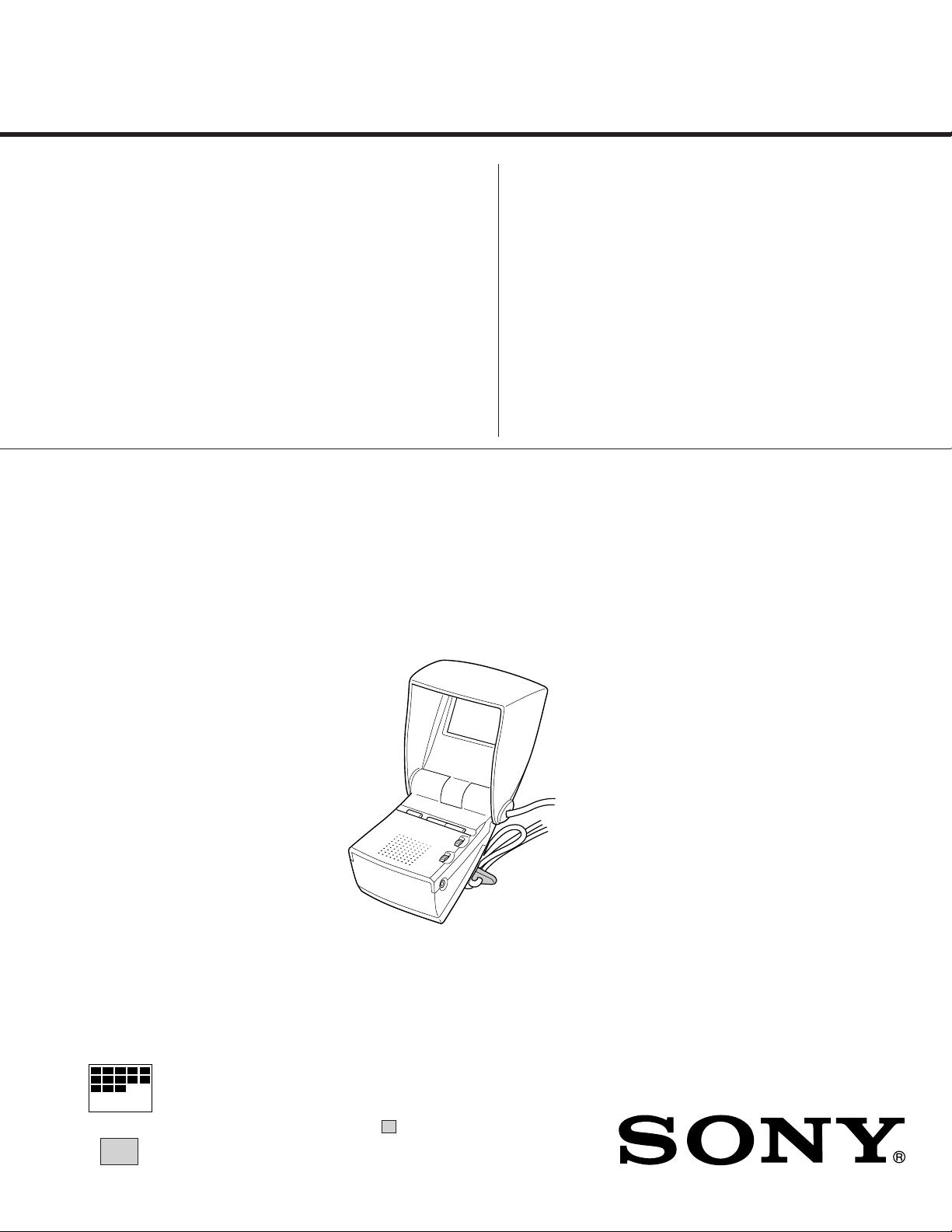
SERVICE MANUAL
MODEL COMMANDER DEST. CHASSIS NO.
–––––– –––––––––––– ––––– –––––––––––
FDL-250T
US
MODEL COMMANDER DEST. CHASSIS NO.
–––––– –––––––––––– ––––– –––––––––––
MICROFILM
∗ Please file according to model size........
2.5
LCD COLOR TV

FDL-250T
SPECIFICATIONS
TV standard American TV standard/NTSC
Channel coverage VHF : 2-13
UHF : 14-69
Antenna VHF/UHF strap antenna
Display format Transmissive type TN liquid cryatal
panel
Drive format TFT/active matrix
Picture 2.5 inches measured diagonally
Viewable image size 49 x 36.5mm (1
Input Audio/video : minijack
Audio : 500mVrms, 47kΩ
Video : 1 Vp-p, 75-ohms, unbalanced,
sync negative
Antenna : VHF/UHF 75Ω (minijack)
Output Headphones : minijack (mono)
Impedance 8-45 ohms
Power requirements 4.5 V DC
AC power adaptor compatible (not
supplied)
Power consumtion Approx. 2.8W
Speaker Ø28mm (1
Temperature range 32˚F-104˚F (0˚C-40˚C)
Dimensions Closed : Approx. 90 x 109 x 71.7mm
(3 9/16 x 4 5/
Fully opened :
Approx. 90 x 194 x 71.7mm
9
/16 x 7 3/4 x 2 13/
(3
excl. projecting parts and controls
Strap length Approx. 1,300mm (51 1/4 in.)
Mass Approx. 360g (12.7oz), excl. batteries
Supplied accessories Strap adjuster
This instruction manual
Warranty
Customer Inquiry Card
Important Safeguards
Optional accessories AC power adaptor AC-E45HG
Size AA (LR6) alkaline batteries
7
/8 x 1 7/16 in.)(wh)
1
/8 in.), 0.1W
13
/16 in.)(w/h/d)
x 2
16
in.)(w/h/d)
16
TABLE OF CONTENTS
Section Title Page
1. GENERAL
Power Sources (see fig. A)...................................................... 3
Operation (see fig. B) .............................................................. 3
External Antenna Connection (see fig. C)............................... 3
Using with Video Equipment (see fig. D)............................... 4
Precsutions .............................................................................. 4
Troubleshooting ...................................................................... 4
WARNING .............................................................................. 4
2. DISASSEMBLY
2-1. Case,A board and H board Removal ............................ 5
2-2. LCD Case and B board Removal ................................. 5
2-3. Service Position ............................................................ 5
3. CIRCUIT ADJUSTMENTS ............................................ 6
4. DIAGRAMS
4-1.Block diagram .................................................................. 8
4-2.Circuit Boards Location ................................................. 11
4-3.Printed Wiring Boards and Schematic Diagrams........... 11
• A Board ....................................................................... 12
• B Board ....................................................................... 16
• H Board ....................................................................... 20
4-4.Semiconductors .............................................................. 21
5. EXPLODED VIEWS
5-1. Chassis Section .............................................................. 22
6. ELECTRICAL PARTS LIST ........................................ 23
Design and specifications are subject to change without notice.
SHORT CIRCUIT THE ANODE OF THE PICTURE TUBE AND THE AN-
(CAUTION)
ODE CAP TO THE METAL CHASSIS, CRT SHIELD, OR CARBON PAINTED ON THE CRT, AFTER REMOVING THE ANODE.
WARNING!!
AN ISOLATION TRANSFORMER SHOULD BE USED DURING ANY SERVICE TO AVOID POSSIBLE SHOCK HAZARD, BECAUSE OF LIVE CHASSIS.
THE CHASSIS OF THIS RECElVER IS DIRECTLY CONNECTED TO THE
AC POWER LINE.
SAFETY-RELATED COMPONENT WARNING!!
COMPONENTS IDENTIFIED BY SHADING AND MARK ! ON THE SCHEMATIC DIAGRAMS, EXPLODED VIEWS AND IN THE PARTS LIST ARE
CRITICAL TO SAFE OPERATION. REPLACE THESECOMPONENTS
WITH SONY PARTS WHOSE PART NUMBERS APPEAR AS SHOWN IN
THIS MANUAL OR IN SUPPLEMENTS PUBLISHED BY SONY. CIRCUIT
ADJUSTMENTS THAT ARE CRITICAL TO SAFEOPERATION ARE IDENTIFIED IN THIS MANUAL. FOLLOW THESE PROCEDURES WHENEVER CRITICAL COMPONENTS ARE REPLACED OR IMPROPER OPERA-
TION IS SUSPECTED.
– 2 –
SECTION 1
GENERAL
The operating instructions mentioned here are partial abstracts from the
Operating Instructions Manual. The page numbers of the Operating
Instruction Manual remain as in the manual. (Part no : 3-867-899-11)
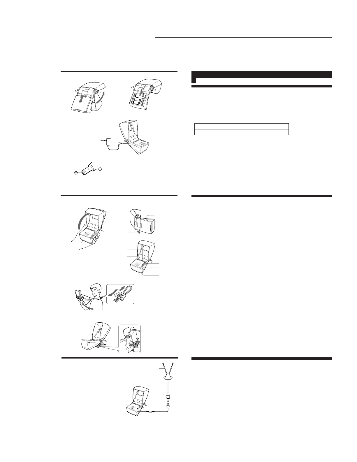
A
1
2
to a wall outlet
3
Polarity of the plug
B
1
2
3
b
CH +/-
OFF/VHF/UHF
AA (LR6)
× 3
i
A/V IN
BRT
VOL
EXT ANT
English
Power Sources (see fig. A)
Alkaline Batteries
Use three Sony LR6 alkaline batteries (not supplied).
1 Open the display and sunshade.
2 Push and slide the battery cover open.
3 Insert three batteries. Be sure to insert the (-) polarity of each battery first as illustrated.
Battery Life: With continuous use, Sony LR6 alkaline batteries will last about 3.0 hours.
Battery Type Size Battery Lif e
LR6 AA Approx. 3.0 hours
Notes
• When the picture becomes dim or the tuning does not lock onto a channel, replace all the
batteries with new ones.
• Switch off the TV and remove the batteries from the unit if the TV will not be used for a
long period of time to avoid battery leakage. Also, be sure to remove dead batteries from the
unit.
House Current
See fig. A-2.
Note
Use only the recommended Sony AC power adaptor, AC-E45HG (not supplied).
(For the polarity of the plug, see fig. A-3)
Operation (see fig. B)
1 Open the display and sunshade.
2 Set the OFF/VHF/UHF switch to VHF or UHF, according to the band you want to watch.
3 Press the CH +/- button to select a channel.
4 Adjust the volume with the VOL dial.
5 Adjust the brightness with the BRT dial.
To switch off the TV: Set the OFF/VHF/UHF
switch to OFF.
To improve the broadcast reception: Extend the strap antenna and adjust the unit’s
orientation until reception is optimal.
Notes
• Grasp the unit as shown in fig. B-1 so that your fingers are not pinched when opening the
display and sunshade.
• You can open the display and sunshade to about 190°. Do not force it open further.
There may be poor broadcast reception in the following areas:
• Faraway from the broadcasting station, or behind a mountain or tall building.
• Inside a train or car, etc.
• Where there is strong interference, such as near a high tension wire, neon sign, or radio
station.
• Near a railway line or expressway, or under air traffic routes.
• In underground shopping centers, tunnels, or solid buildings.
Listening with headphones: Connect headphones (not supplied) to the i (headphones)
jack. The sound is heard from both sides of the headphones, but the sound is monaural.
How to use the TV
First, place the adjuster on the strap as shown on the left, then adjust to a confortable position
and wear the TV around your neck. You can adjust the length of the strap. (See fig. B-2)
You can also place the TV on a flat surface using the supplied adjuster as a tilt stand. Attach the
adjuster to the rear of the unit. (See fig. B-3)
C
1 Indoor antenna
2 75 Ω external antenna cable (not supplied)
1
2
To EXT ANT
External Antenna Connection (see fig. C)
Connect a 75 Ω external antenna cable (not supplied) to the TV. This will improve the TV’s
reception.
– 3 –
D
Camcorder
VCR
To A/V IN
To video output
To audio output
AUDIO
VIDEO
Using with Video Equipment (see fig. D)
Connect video equipment (such as VCR or camcorder) to the unit using an audio/video cable
(miniplug y phono plug) (not supplied).
When you connect an audio/video cable to the unit, the unit automatically selects the input only
from the video equipment.
After connecting, start playback on the video equipment connected to the unit.
About the A/V IN jack
The A/V IN jack is a minijack, and the signal connections are aligned as shown on the left. This
alignment may be opposite depending on the equipment.
In such case (if no sound is heard and no picture is seen), connect the video plug to the audio
output jack, and the audio plug to the video output jack of the equipment.
English English
Precautions
• Use the recommended Sony AC power adaptor,
AC-E45HG (not supplied). Do not use any other type of
AC power adaptors for this unit.
• Do not open the unit. Refer servicing to qualified
personnel only.
• Do not place the unit in a hot or humid place, or in a place
subject to excessive dust or vibration.
• Avoid rough handling.
• Clean the unit with a soft cloth slightly dampened with a
mild detergent solution. Never use strong solvents, such as
thinner or benzine, as they may damage the finish.
• Do not touch the AC power adaptor with wet hands. Doing
so may cause an electric shock.
• Do not touch the external antenna cord or AC power
adaptor during stormy weather. Doing so may result in an
electric shock.
• Do not use while driving, walking or engaging in any
activity where full attention is required.
• Keep out of reach of children. Strap antenna could cause
strangulation.
• When opening the display, be careful not to pinch your
fingers in the hinge. Also, be careful that the sunshade
does not close on your fingers while viewing.
Troubleshooting
Before you contact your nearest Sony dealer or authorized
service center, refer to the following troubleshooting guide.
No picture, no sound
• The AC power adaptor is disconnected.
• Incorrect battery polarity.
• Weak batteries. Replace all the batteries with new ones.
• The external antenna is disconnected.
• The video equipment is not connected properly.
Good picture, no sound
• Turn the VOL dial to the + direction.
• The headphones are connected.
• Weak batteries. Replace all the batteries with new ones.
• The video equipment is not connected properly.
Good sound, no picture
• Weak batteries. Replace all the batteries with new ones.
• Increase the brightness by turning the BRT dial toward the
+ direction.
• The video equipment is not connected properly.
Snowy or indistinct picture
• Improper tuning.
• Extend the strap antenna fully.
• Adjust the strap antenna direction.
• Connect an external antenna (not supplied).
Dotted lines or stripes
Often caused by interference from other electrical appliances
such as a hair dryer, car, or motorcycle.
• Relocate the strap antenna away from the source of
interference.
• Extend the strap antenna fully.
• Connect an external antenna (not supplied).
WARNING
T o prevent fire or shoc k hazard, do not expose the unit to
rain or moisture.
This symbol is intended to alert the user to the
presence of uninsulated “dangerous voltage” within the
product’s enclosure that may be of sufficient magnitude
to constitute a risk of electric shock to persons.
This symbol is intended to alert the user to the
presence of important operating and maintenance
(servicing) instructions in the literature accompanying
the appliance.
CAUTION
This device complies with part 15 of the FCC Rules.
Operation is subject to the following two conditions:
(1) This device may not cause harmful interference, and
(2) This device must accept any interference received, including
interference that may cause undesired operation.
You are cautioned that any changes or modifications not expressly
approved in this manual could void your authority to operate this
equipment.
Owner's Record
The model and serial numbers are located at the front side. Record the
serial number in the space provided below. Refer to these numbers
whenever you call upon your Sony dealer regarding this product.
Model No. FDL-250T Serial No.
– 4 –
SECTION 2
SECTION 3
DISASSEMBLY
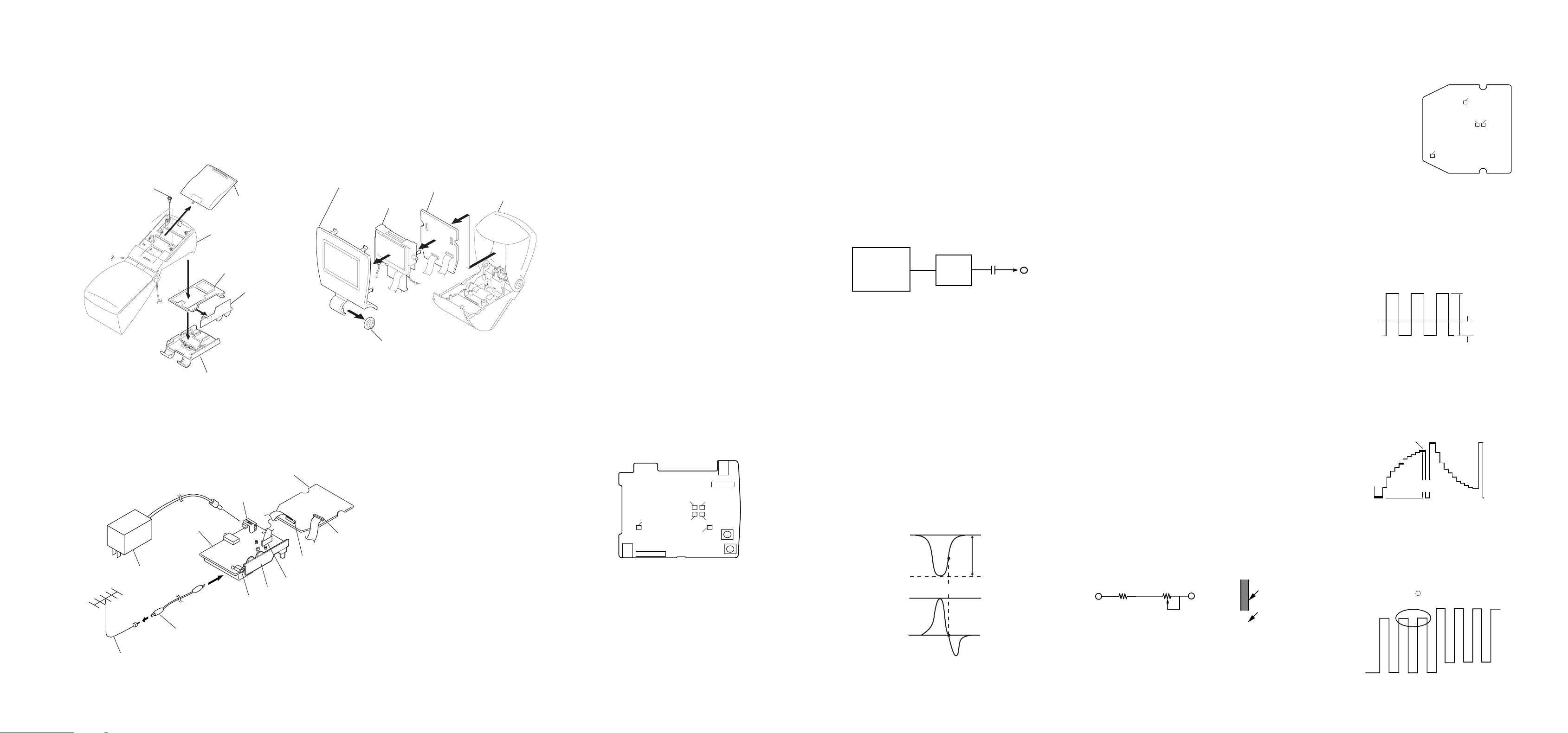
2-1. CASE, A BOARD AND H BOARD REMOVAL
2 Three screws
(7-685-105-19)
5 Battery case (upper)
2-3. SERVICE POSITION
A board
AC power adaptor
Cord
Antenna
1 Battery cover
Battery case (lower)
3 A board
4 H board
B board
J601
H board
J101
CN301
CN201
2-2. LCD CASE AND B BOARD REMOVAL
2 LCD case (upper)
3 LCD holder
1 Hinge collar
CN401
4 B board
LCD case (lower)
CIRCUIT ADJUSTMENTS
[SETUP](A BOARD )
1. Apply a DC voltage of 4.5V±0.1V to the J601 terminal (DC
input jack) on the A board.
2. With S601 on the A board at UHF position, set the User Control R V -550(VOL) and R V-901(BRT) on the H board to their
mechanical centers.
[+5.0V ALIGNMENT (RV600)](A BOARD )
Using a digital voltmeter measuring the voltage between
JL09 (+5.0V) and JL87 (A.GND). Adjust RV600 to obtain
the value shown below.
Standard Value = 4.55V± 0.02VDC
S601 position = UHF position
[+30.0V CHECK](A BOARD )
Check the voltage across JL07 (+30.0V) and JL87 (A.GND) .
Standard Value = 32.0V±2.0VDC
[+7.5V CHECK](A BOARD )
Check the voltage across JL08 (+7.5V) and JL87 (A.GND) .
Standard Value = 7.0V± 0.3VDC
[-10.0V CHECK](A BOARD )
Check the voltage across JL10 (-10.0V) and JL87 (A.GND) .
Standard Value = -9.5V± 0.6VDC
- A board - (Component side)
J601
EXT ANT
RV600
J601
DC IN JACK
RV002
RV001
RV201
RV004
RV003
T201
T202
< A BOARD ALIGNMENT >
3-1.VIF.AFT ROUGH ALIGNMENT (T201, T202)
[SETUP]
1. Set S601 on the A board to VHF position.
2. Apply no signal to JL119 (RF).
3. Connect a 1 kΩ resistor between JL09 (+5.0V) and
JL13 (RF AGC).
4. Apply a sweep signal across JL12 (IF) and JL14(IF GND).
(Fig. 3-1)
Note : Set the sweep signal for JL12 to -30±5dBm. Keep the
distance to the ATT output JL12 as short as possible.
0.01µF
SWEEP
MARKER
GENERATOR
fo=45.75MHz±5kHz
ATT
JL12
75Ω 6dB
Fig. 3-1
1. Connect an oscilloscope between JL86 (VIDEO) and JL87
(A.GND) and apply an external voltage (MGC) to JL26 to
obtain a waveform as shown in Fig. 3-2 (make sure not to
clip the extremely short portion).Adjust T202 so that the position at 45.75 MHz is the lowest point.
Note : Align JL26 (MGC) external voltage for approximately
a 1.0 Vp-p. Make sure that the JL26 (MGC) external
voltage does not exceed 4.3VDC.
2. Remove the external voltage (MGC) from JL26.
3. Connect an oscilloscope between JL02 (AFT) and JL01
(D.GND) and make a rough adjustment of T201 so that waveform is close to zero at the 45.75 Mhz position.
4. Remove the 1 kilohm resistor connected between JL09 (+5.0V)
and JL13 (RF AGC).
10Vp-p
45.75MHz
0
Fig. 3-2
3-2.AFT FINE ADJUSTMENT (T201)
1. Connect a 1 kilohm resistor between JL09 (+5.0V) and JL13
(RF AGC).
Note : Perform this adjustment as the last step in the
process since drift may occur due to aging.
2. Switch the sweep signal to CW.
fo= 45.75 MHz±5 kHz, -30±5dBm
Apply the above signal between JL12 (IF) and JL14 (IF GND)
and then make a fine adjustment of T201 so that the level be-
tween JL02 (AFT) and JL01 (D.GND) reaches2.2V±0.4VDC.
3. Remove the 1 kilohm resistor connected between JL09 (+5.0V)
and JL13 (RF AGC).
3-3.RF. AGC ALIGNMENT (RV201)
1. Set S601 to VHF position and receive a VHF color bar signal
issued from a signal generator.
2. Adjust RV201 and align the screen for the optimal point so
that the snow noise disappears.
3-4.CHANNEL DiISPLAY POSITION ALIGNMENT
(RV001, RV002, RV004)
1. Set S601 to VHF position, a potentiometer (47kΩ±15kΩ)
across JL06(CS) and JL09 (+5.0 V) as shown in Fig. 2-6 and
short the points JL04(CH CAL) and JL01 (D.GND).
2. Receive channel 2 and align the channel display positions with
R V002(VP).
3. Receive channel 13 and align the display bar with R V004(VA).
4. Align while performing tracking to mutual interference in the
above steps 2 and 3.
5. Receive channels 3 & 4 and confirm that the display bar is
within the standards.
6. Set S601 to UHF.
7. Receive channel 14 and align the display position with
RV001(UP).
8. Receive channel 69 and confirm that the display bar is within
the standards. If not within standards, align with R V001 so it
is within standards.
Once again receive channel 14 and confirm that the display bar
is within the standards.
Note : Use caution since shifting channel 69 will also
cause channel 14 to shift.
9. Remove the potentiometer (47kΩ+15kΩ) you connected between JL06(CS) and JL09(+5.0V). Also remove the short you
connected between points JL04 (CH CAL)and JL01(D.GND).
JL06 (CS)
JL09(+5.0V)
Display bar
15kΩ
VR(47kΩ)
Channel No.
6
*Channel No. and display
bar are to be in line.
Fig. 3-4
Fig. 3-4
< B BOARD ALIGNMENT >
- B board (Component side)
RV306
RV301
RV302
RV308
3-5.V COM ALIGNMENT (RV302, RV306)
1. Adjust BRT VR (RV901) to1.740±0.005VDC, between
JL301(BRT) and JL307 (A.GND).
2. Observe the waveform across JL411 (V COM) and
JL407(GND).
3. Adjust RV302 (COM AMP) and RV306 (V COM DC) so that
the waveform resembles that in Fig. 3-5.
Note : The voltage at pin 37 (COMMON AMP) of IC302 shall
be a minimum of 1.8V.
5.0V±0.1Vp-p
0V
-1.4V±0.1Vp-p
Fig. 3-5
3-6.CONTRAST ALIGNMENT (RV301)
1. Receive the stepped waveform signal in 10 steps.
2. Observe the waveform across JL421(VG) and JL407(GND).
3. Align RV301 (CONT) so that 100IRE section matches the
standard below. (Fig. 3-6)
10thstep
(101IRE)
3.0V±0.1Vp-p
Fig. 3-6
3-7.COLOR PHASE (TINT) ALIGNMENT (RV-308)
1. Receive the color bar signal from the signal generator.
2. Observe the waveform across JL422(VB) and JL407(GND).
3. Adjust RV308 (TINT) so that the waveform level resembles
that of Fig. 3-7.
Align so the portion is parallel and linear.
Fig. 3-7
– 5 –
– 6 – – 7 –
ANT
4-1. BLOCK DIAGRAM
J101
EXT ANT
TU101
TUNER
BETTERY
RF IN
IF
AGC
HB
LB
UB
MB
TU
J701
DC IN 4.5V
DRY
U/V SW
Q010
S601(1/2)
OFF/VHF/UHF
VH/VL SW
Q011
VOLTAGE
SELECT
Q001
D607
IF AMP
Q201
VH/VL SW
Q012
DC AMP
Q002
RV001
UP
RV002
VP
RV004
VA
S601(2/2)
OFF/VHF/UHF
F601
+5V
D605
L401
FILTER
SWF201
ELECTRONIC TUNING
28
27
26
18
19
20
23
COMPOSITION
GENERATOR
UN4.5V
BAND
SW
BT
INITIAL
BS
SET
IC600
SWITCHING CONTROL
3
VCC
1
-IN
OUT
OSC
BR/CTL
IC001
INITIAL
5
7
4
TUNING
CONTROL
INPUT
CONTROL
AUTO
RETURN
SET
SW REG OUT
DISCHARGE
Q600
CONT
Q602
CHARGE/
3
PULSE WIDTH
SET
COMPARATOR
9
8
UN4.5V
DEFECT
OUT PUT
SIGNAL
DEFECT
BAR
OUT PUT
T601
+30V
14
10
15
30
31
1
3
4
2
6
7
Vcc OUT
Q601
5
6
AFT SW
Q006,007
4
Q003,004
D602
D603
D601
D604
MUTE
RV201
RF AGC
MUTE
Q203
CF202
S002
CH +
+30V
-10V
+7.5V
+5V
Vcc CONT
Q604,605
S001
CH -
+5V
T201
+5V
IC302
Y/C/J
BRT
-10V
IND
VHF
UHF
5V
30V
HP
RV550
VOL
1
2
4
5
6
7
9
10
12
14
17
18
CN301
J801
A/V IN
-10V
+5V
+7.5V
+30V
RV901
BRT
UN4.5V
SPEAKER
INVERTER
Q302
SYNC SEP
Q401,402
IC401
OSC
3
VIDEO IN
36
SYNC SEP
39
SW
42
R IN
41
G IN
SW
Q305
IC403
SW
Q306
29
34
35
BRIGHT
SYNC IN
SYNC OUT
LCD CONTROL
34
HSY/O
COMMON FRP
30
VSY/I
35
Csync
-
3
+
1
L401
4
O
NPD
15
25
OSC/O
26
OSC/I
UN4.5V
FRP
STHL
STHR
CKV
CK1A
CK2A
CK3A
STV1
STV2
OEH
OEV
INV/O
INV/I
Q1HA
LRA
UDC
32
33
13
14
16
17
18
19
10
11
3
4
1
2
8
40
37
Q703,704
OSC SW
+5V
44
PFRP
OSC 1
OSC 2
COMMON AMP
COMMON OUT
Q701
Q702
R OUT
G OUT
B OUT
CONTRAST
TINT
VCO OUT
VCO IN
19
21
24
2
13
37
38
16
14
UN4.5V
BUFFER
Q304
3
2
3.58MHz
3
4
1
5
IC301
AMP
X301
2
RV301
CONT
RV308
TINT
RV302
COMP AMP
7
RV306
VCOM DC
+30V
T701
+5V
-10V
8
9
STHL
OEH
CK1A
CK2A
CK3A
STHR
STV2
OEV
CKV
STV1
VGH REG
Q303
D302
FR701
CN401
1
STHL
2
OEH
3
Q1H
4
CPH1
5
CPH2
6
CPH3
8
VB
9
VG
10
VR
12
L/R
13
STHR
14
AVDD
15
VCOM
16
VGH
17
VCC
18
STVL
19
OEV
20
CKV
21
U/D
22
STVR
24
VGL
TO
MONITER
(LCD)
CN201
UN4.5V
CN550
1
2
4
5
7
10
1
2
4
5
6
7
9
10
12
14
17
18
CN501
1SP
2 SP.GND
VIDEO
7.5V
UNREG
UNREG
IC201
VIF/SIF DET
7
6
3
16
14
15
16
17
21
23
IF AMP
AGC
FM
DET
AFT
SYNC
SEP
VIDEO
DET
BUFFER
LIMITER
VIDEO
AMP
IC501
AUDIO AMP
2
-IN
3
-IN
19
20
13
10
18
22
IND SW
Q005,008
OUTPUT
45.75MHz
AUDIO AMP
CF203
CF201
6
7
V+
T202
Q803
V BUFFER
Q202
+5V
UN4.5V
V BUFFER
Q801
CN202
10
15V
2 BRT
4 AUDIO
5 AUDIO
7
AUDIO
AUDIO
-10V
+5V
+7.5V
+30V
A
(TUNER,ELECTRONIC TUNING,VIF,SIF,POWER)
RV600
+5V ADJ
UN4.5V
J550
HEAD
H
PHONE
(Y/C/J,LCD CONTROL)
B
(HEAD PHONE,BRT/VOL VR)
– 9 –– 8 –
– 10 –
 Loading...