

Sony EXRC-340 Service manual

EXR-C205/XR-C340
SERVICE MANUAL
US Model
Canadian Model
EXR-C205
E Model
XR-C340
Refer to RM-X2S/X3S SERVICE MANUAL (9-960-039-∏)
issued previously for information of remote commander
(RM-X2S) supplied with XR-C340.
Specifications
Cassette Player section
Tape track 4-track 2-channel stereo
Wow and flutter 0.08% (WRMS)
Frequency response 30-18,000 Hz
Signal-to-noise ratio 58 dB
Tuner section
FM
Tuning range EXR-C205:
87.5-107.9 MHz
XR-C340:
FM tuning interval:
50 kHz/200 kHz
switchable
87.5-108.0 MHz
(at 50 kHz step)
87.5-107.9 MHz
(at 200 kHz step)
Antenna terminal External antenna connector
Intermediate frequency 10.7 MHz
Usable sensitivity 8 dBf
Selectivity 75 dB at 400 kHz
Signal-to-noise ratio 65 dB (stereo),
68 dB (mono)
Harmonic distortion at1 kHz
0.5% (stereo),
0.3% (mono)
Separation 35 dB at 1 kHz
Frequency response 30-15,000 Hz
Capture ratio 2 dB
Photo : XR-C340
Model Name Using Similar Mechanism NEW
T ape Transport Mechanism T ype
Power amplifier section
Outputs Speaker outputs
(sure seal connectors)
Speaker impedance 4-8 ohms
Maximum power output 35 W × 4 (at 4 ohms)
General
Outputs Power antenna control
lead/Power amplifier
control lead/Telephone
mute control lead (XR-C340 only)
Rear line out (1)
Tone controls Bass ±8 dB at 100 Hz
Treble ±8 dB at 10 kHz
Power requirements 12V DC car battery
(negative ground)
Dimensions Approx. 188 × 58 × 184 mm
(w/h/d)
Mounting dimensions Approx. 182 × 53 × 164 mm
(w/h/d)
Mass Approx. 1.3 kg
Supplied accessories Parts for installation and
connections (1set)
Front panel case (1)
Rotary remote RM-X2S
(XR-C340 only)
Design and specifications are subject to change without
notice.
MG-25A-136
AM
Tuning range EXR-C205
530-1,710 kHz
XR-C340
AM tuning interval:
9 kHz/10 kHz switchable
531-1,602 kHz
(at 9 kHz step)
530-1,710 kHz
(at 10 kHz step)
Antenna terminal External antenna connector
Intermediate frequency 10.71 MHz/450 kHz
Sensitivity 30 µV
MICROFILM
FM/AM CASSETTE CAR STEREO

TABLE OF CONTENTS
SERVICING NOTES
1. GENERAL ................................................................... 3
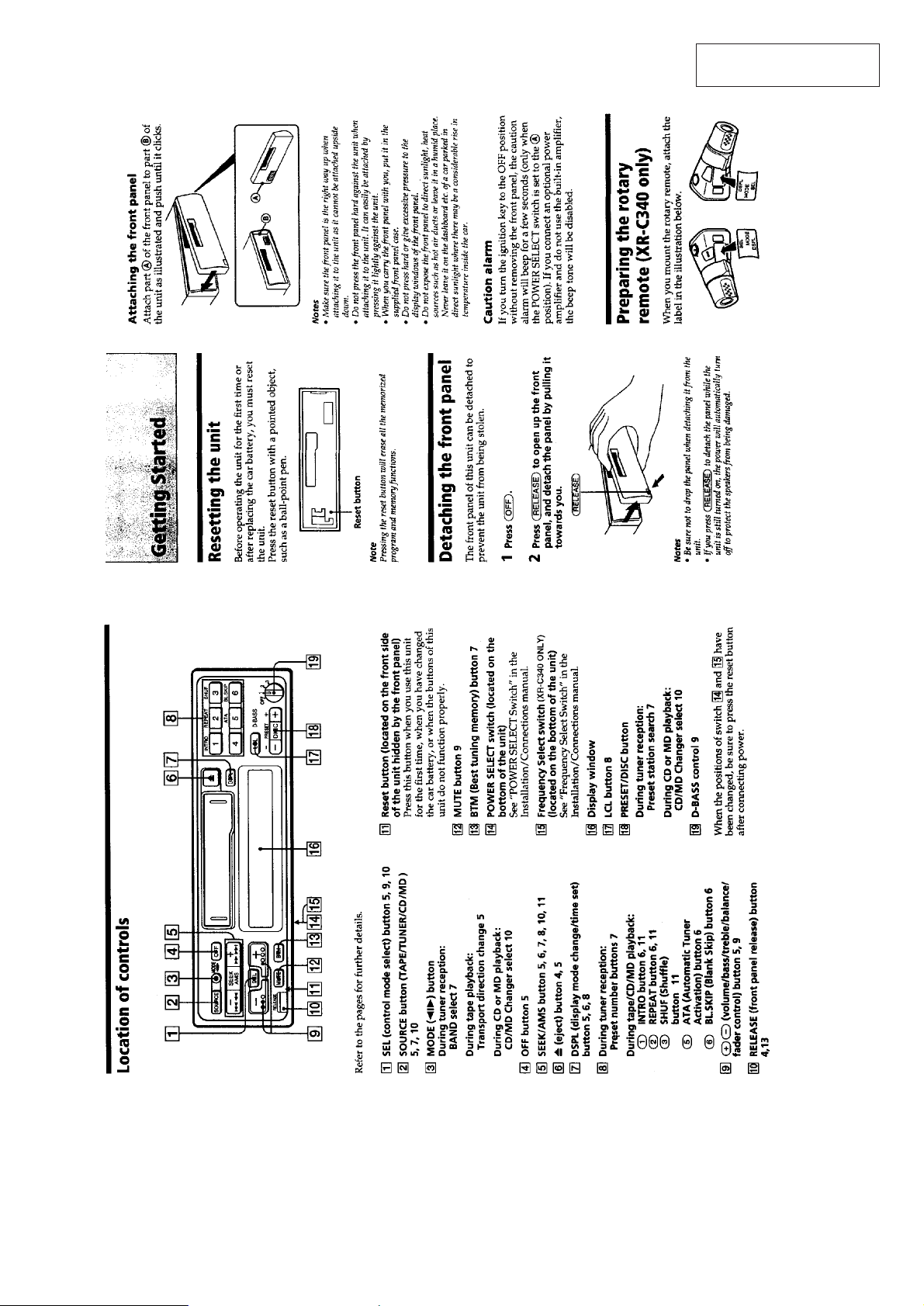
Location of Controls ........................................................ 3
Resetting the Unit ............................................................ 3
Detaching the Front Panel ............................................... 3
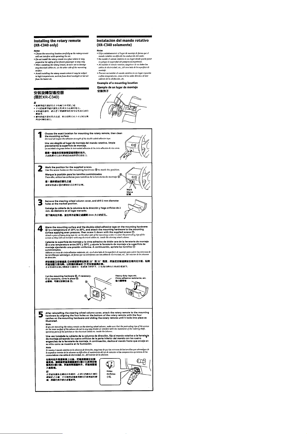
Preparing the Rotary Remote .......................................... 3
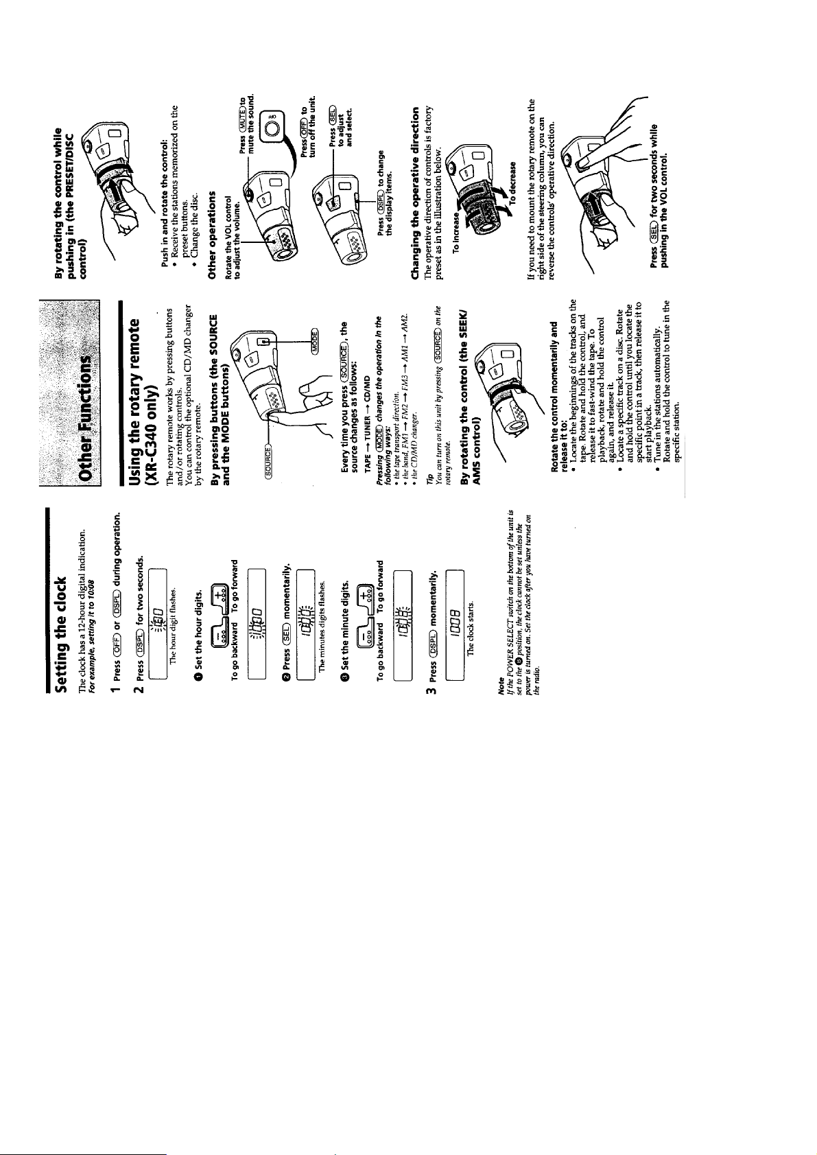
Setting the Clock ............................................................. 4
Using the Rotary Remote ................................................ 4
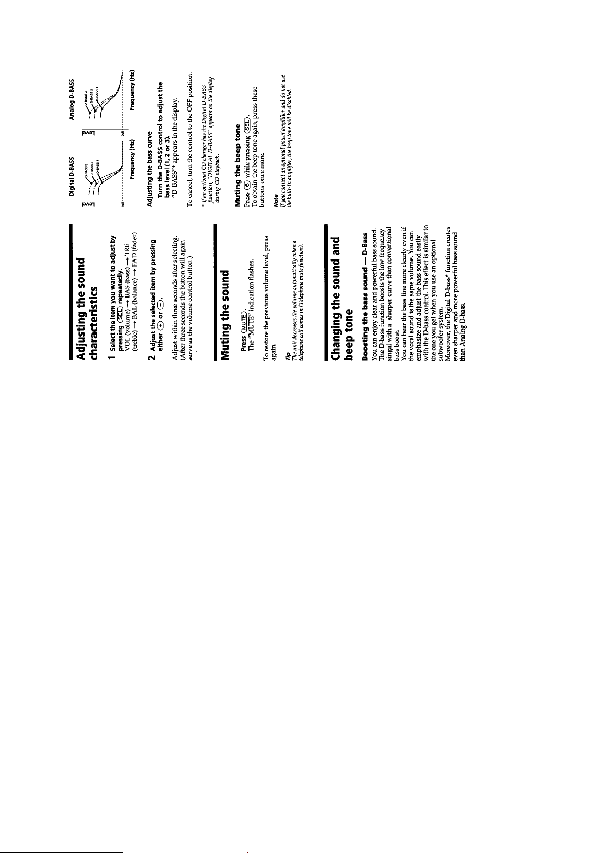
Adjusting the Sound Characteristics ............................... 5
Muting the Sound ............................................................ 5
Changing the Sound and Beep Tone................................ 5
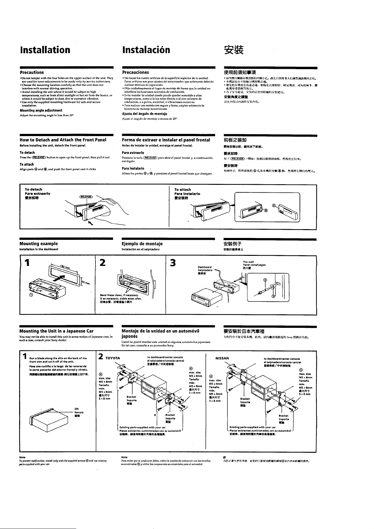
Installation ....................................................................... 6
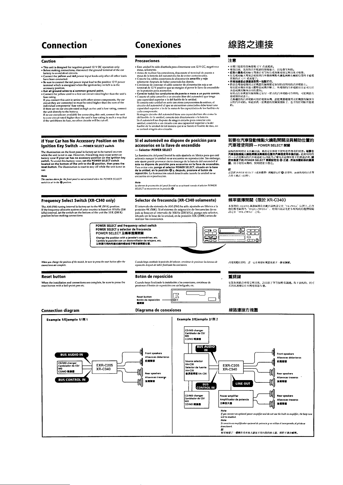
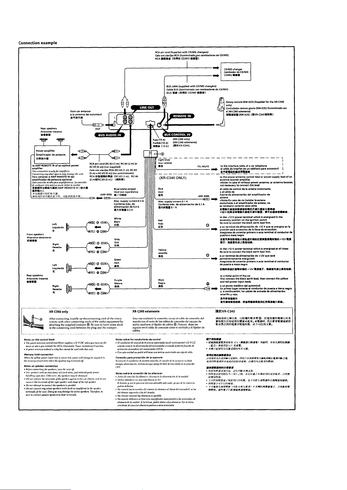
Connections ..................................................................... 7
2. DISASSEMBLY.......................................................... 10
3. ASSEMBLY OF MECHANISM DECK ........... 12
4. MECHANICAL ADJUSTMENTS ....................... 15
5. ELECTRICAL ADJUSTMENTS ...................... 15
6. DIAGRAMS
6-1. IC Pin Function Description ............................................ 16
6-2. Printed Wiring Board –MAIN Section– ......................... 20
6-3. Schematic Diagram –MAIN Section–............................ 23
6-4. Printed Wiring Board –KEY Section– ........................... 27
6-5. Schematic Diagram –KEY Section– .............................. 29
Flexible Circuit Board Repairing
• Keep the temperature of the soldering iron around 270 ˚C dur-
ing repairing.
• Do not touch the soldering iron on the same conductor of the
circuit board (within 3 times).
• Be careful not to apply force on the conductor when soldering
or unsoldering
Notes on chip component replacement
• Never reuse a disconnected chip component.
• Notice that the minus side of a tantalum capacitor may be dam-
aged by heat.
7. EXPLODED VIEWS .......................................... 31
8. ELECTRICAL PARTS LIST ................................ 34
– 2 –
SECTION 1
GENERAL
This section is extracted
from instruction manual.
– 3 –
– 4 –
– 5 –
– 6 –
– 7 –
– 8 –
– 9 –
SECTION 2
DISASSEMBLY
Note: Follow the disassembly procedure in the numerical order given.
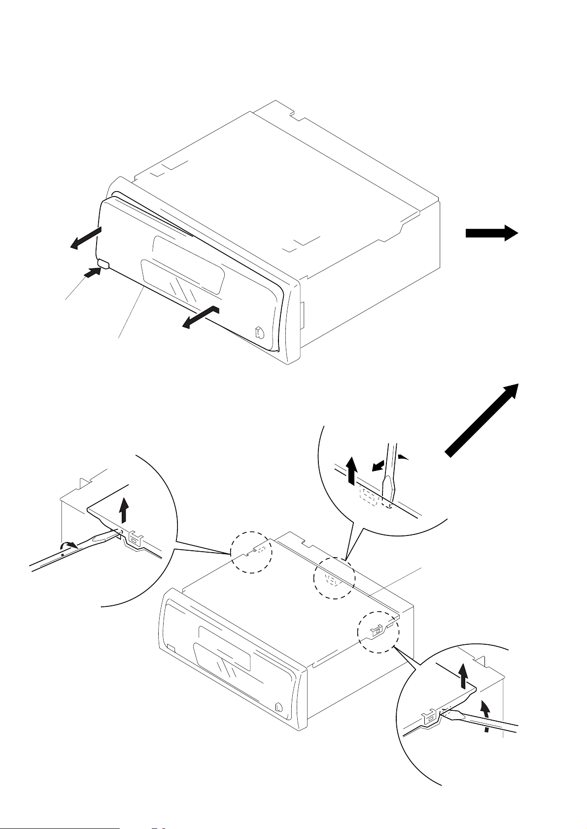
FRONT PANEL ASS’Y
1
Push the button
(release).
A
2
Remove the front panel ass’y
to the direction of the arrow A.
COVER ASS’Y
1
2
2
1
3
cover ass’y
2
1
– 10 –

SUB PANEL, MECHANISM DECK (MG-25A-136)
3
connector
(CN302)
2
sub panel
1
three screws
(PTT2.6 × 8)
5
screw
(PTT2.6 × 6)
6
mechanism deck
(MG-25A-136)
4
flexible flat cable
(CN301)
1
three screws
(PTT2.6 × 8)
MAIN BOARD, HEAT SINK
2
two ground point
screws
3
main board
1
5
heat sink
4
eight screws
(PTT2.6 × 10)
screw
(PTT2.6 × 8)
– 11 –
1
two screws
(PTT2.6 × 8)
SECTION 3
ASSEMBLY OF MECHANISM DECK
Note: Follow the assembly procedure in the numerical order given.
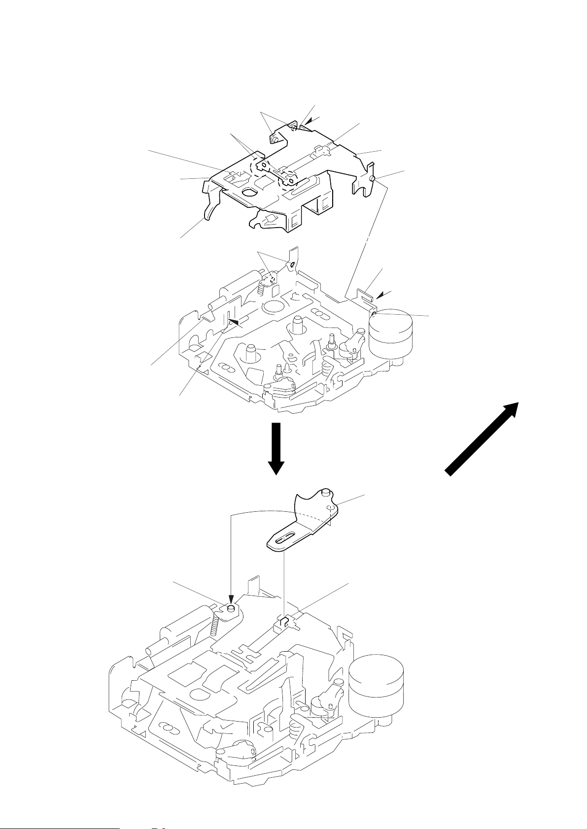
HOUSING
4
Fit claw on B part.
3
2
Install the hanger onto
two claws of the housing.
Put the housing
under A part.
housing
A
part
5
Fit projection on C part.
C
part
7
Hold the hanger by bending the claw.
1
Install the catch to the hanger.
hanger
6
Fit projection on D part.
8
Hold the hanger by
bending the claw.
D
part
ARM (SUCTION)
B
projection
part
2
Move the arm (suction) in the arrow
direction and fit on projection.
1
Fit the arm (suction) on the shaft.
– 12 –
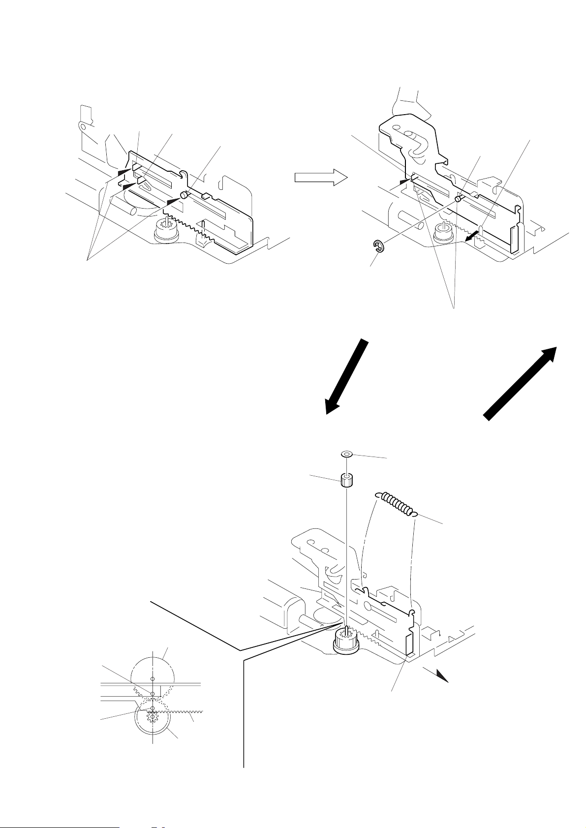
LEVER (LDG-A) / (LDG-B)
shaft
A
shaft
1
Fit the lever (LDG-A) on
shafts A – C and install it.
B
shaft
C
shaft
A
4
type-E stop ring 2.0
2
Pull the lever in the
arrow direction.
shaft
B
3
Fit the lever (LDG-B) on
shafts A and B and
install it.
GEAR (LDG-FT)
hole
hole
gear (LDG-D)
lever (LDG-A)
gear (LDG-FB)
4
gear (LDG-FT)
5
polyethylene washer
1
2
Move the lever (LDG-B)
in the arrow direction.
tension spring (lever LDG)
3
Align hole in the gear (LDG-D)
with hole in the lever (LDG-A).
– 13 –
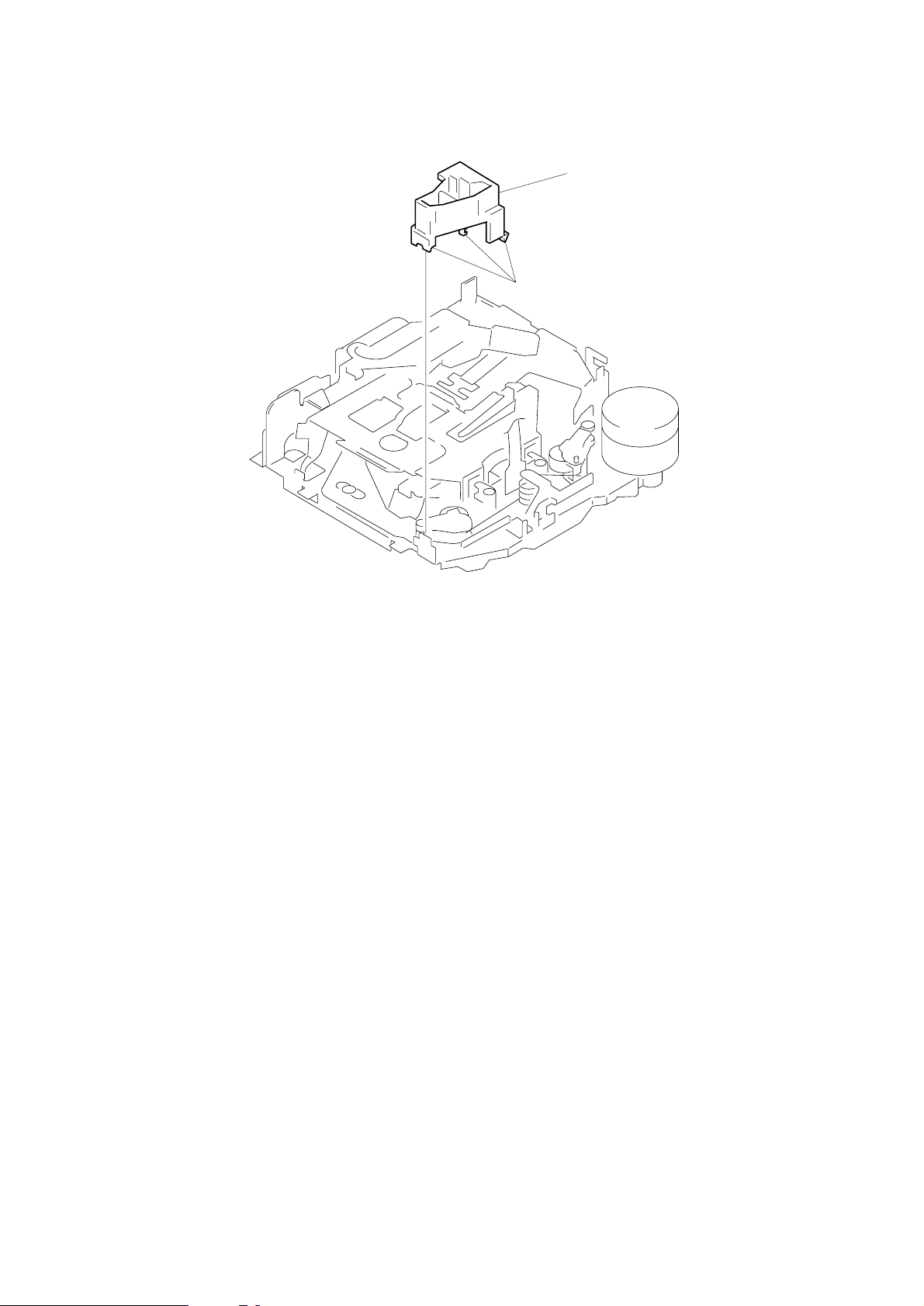
GUIDE (C)
1
three claws
2
guide (C)
– 14 –
 Loading...