

Page 1

LIVE PRODUCTION CONTROL SOFTWARE
ELC-MVS01
User’s Guide [English]
1st Edition (Revised 5)
Software Version 3.1.0 and Later
Page 2

NOTICE TO USERS
© 2009 Sony Corporation. All rights reserved. This
manual or the software described herein, in whole or in
part, may not be reproduced, translated or reduced to any
machine readable form without prior written approval
from Sony Corporation.
SONY CORPORATION PROVIDES NO WARRANTY
WITH REGARD TO THIS MANUAL, THE
SOFTWARE OR OTHER INFORMATION
CONTAINED HEREIN AND HEREBY EXPRESSLY
DISCLAIMS ANY IMPLIED WARRANTIES OF
MERCHANTABILITY OR FITNESS FOR ANY
PARTICULAR PURPOSE WITH REGARD TO THIS
MANUAL, THE SOFTWARE OR SUCH OTHER
INFORMATION. IN NO EVENT SHALL SONY
CORPORATION BE LIABLE FOR ANY
INCIDENTAL, CONSEQUENTIAL OR SPECIAL
DAMAGES, WHETHER BASED ON TORT,
CONTRACT, OR OTHERWISE, ARISING OUT OF OR
IN CONNECTION WITH THIS MANUAL, THE
SOFTWARE OR OTHER INFORMATION
CONTAINED HEREIN OR THE USE THEREOF.
Sony Corporation reserves the right to make any
modification to this manual or the information contained
herein at any time without notice.
The software described herein may also be governed by
the terms of a separate user license agreement.
Trademark Notice
• Microsoft and Windows are registered trademarks of
Microsoft Corporation in the United States and other
countries.
• Avid and iNEWS are either registered trademarks or
trademarks of Avid Technology, Inc. or its subsidiaries
in the United States and/or other countries.
• ENPS is a registered trademark of Associated Press.
• Other system names, product names and company
names appearing in this manual are trademarks or
registered trademarks of their respective holders. In this
manual such names are not indicated by ® or ™
symbols.
2
Page 3
Table of Contents
Overview
Chapter 1 Overview
The
revised.
Introduction......................................................................................9
Features..........................................................................................11
ELC-MVS01 Software Products.................................................... 11
System Configurations .................................................................13
Basic Operation Flow .............................................................15
Overview of Playlist Creation ....................................................... 16
mark shows that the features or explanations have been newly added or
Configuration of This Guide ................................................................. 9
Notational Conventions......................................................................... 9
Software Components Products .................................................. 11
Optional Software Products................................................................. 12
Basic System Configuration................................................................ 13
Equipment to be Used in the System................................................... 13
Playlist Creation Flow ................................................................. 16
Elements of a Playlist .......................................................................... 19
Chapter 2 Names and Functions of Parts
Initial Setup Window...................................................................... 20
Initial Setup Main Menu...................................................................... 20
Video Switcher Settings Window ....................................................... 21
Audio Mixer Settings Window............................................................ 22
Shot Box Module Assign Window...................................................... 25
DDR(VDCP) File List Creation Window ................................... 26
Audio Server File List Creation Window............................................ 27
Studio Monitor Settings Window........................................................ 28
Icon Manager Window................................................................... 29
Icon Manager Main Window .............................................................. 29
Video Icon Window ............................................................................ 32
Audio Icon Window ............................................................................ 33
Transition Icon Window...................................................................... 34
Effect Icon Window ............................................................................ 35
Source Window ................................................................................... 36
Category Window................................................................................ 37
ELC Plug-in Window...................................................................... 38
Quick Cue Tab..................................................................................... 40
Table of Contents
3
Page 4

Cue Edit Tab........................................................................................ 41
OA Playlist and Playlist Viewer Windows ............................43
Alarm Monitor Window.................................................................. 47
Alarm Monitor Application................................................................. 47
Alarm Monitor Window...................................................................... 48
Preparations
Chapter 3 Making the Initial Setup
Overview.........................................................................................50
Starting the Initial Setup Application........................................... 51
Making the Video Switcher Settings ............................................53
Associating the V/K Pair Numbers with Video Icons......................... 53
Specifying the Transition Rate Options .............................................. 56
Making the Audio Mixer Settings ................................................. 57
Associating Fader Numbers with Audio Icons.................................... 58
Associating Fader Numbers with Back Faders of the Audio Fader Panel
for Constant Manual Operation ................................................. 60
Disabling Control of Faders of the Audio Mixer from the ELC-MVS01
System........................................................................................ 61
Specifying the Name for an AUX Bus for the Mix-Minus Feature .... 62
Specifying the Audio Level Options ................................................... 63
Specifying the Fade In/Out Time Options .......................................... 64
Assigning Functions to the Shot Box Module Buttons .............65
Assigning a Function to a Button ................................................ 65
Assigning a Table to a Shot Box Module............................................ 69
Specifying the Name of a Button ........................................................ 70
Removing the Assigned Function ....................................................... 72
Managing Video Material
- Creating the DDR(VDCP) File List ....................................... 73
Creating the File List........................................................................... 73
Changing the Order of the Files .......................................................... 75
Deleting Files from the List................................................................. 76
Managing Audio Material
- Creating the Audio Server File List..................................... 77
Creating the File List........................................................................... 77
Changing the Order of the Files .......................................................... 78
Deleting Files from the List................................................................. 79
Making the Studio Monitor Settings ............................................80
Enabling Control of an AUX Bus from the ELC-MVS01 System ..... 80
Specifying the Initial Source Device for an AUX Bus ....................... 81
Specifying the Name for an AUX Bus................................................ 83
Specifying the Length of Delay for Switching the OA and NEXT
Cues............................................................................................ 84
4
Table of Contents
Page 5

Chapter 4 Preparing Icons (Icon Manager)
Overview of Icons .........................................................................85
Starting the Icon Manager Application ........................................ 89
Managing Icons..............................................................................90
Creating Icons...................................................................................... 90
Setting Icons ........................................................................................ 91
Editing Icons...................................................................................... 100
Moving an Icon within the Icon Library ........................................... 100
Deleting Icons.................................................................................... 101
Managing Categories ..................................................................102
Creating Categories ........................................................................... 102
Setting Categories.............................................................................. 103
Editing Categories ............................................................................. 105
Moving Categories ............................................................................ 106
Deleting Categories ........................................................................... 106
Registering an Icon in a Category.............................................. 107
Moving an Icon within a Category.................................................... 108
Deleting Icons from a Category ........................................................ 108
Importing Camera Shots and Creating Icons............................ 110
List of Required Settings in Icon Creation and Category
Registration ...........................................................................114
Chapter 5 Preparing Cues (ELC Plug-in)
Starting the ELC Plug-in Application......................................... 116
Managing Cues ............................................................................118
Creating a Cue ................................................................................... 118
Details of Settings ..................................................................... 119
Editing a Cue Registered in Quick Cue............................................. 132
Renaming a Cue ................................................................................ 133
Deleting a Cue ................................................................................... 133
Restoring a Deleted Cue.................................................................... 133
Moving a Cue within a Folder........................................................... 134
Copying a Cue to Another Folder ..................................................... 134
Managing Cue Folders ................................................................135
Creating a Cue Folder........................................................................ 135
Renaming a Cue Folder..................................................................... 135
Deleting a Cue Folder........................................................................ 136
Moving a Cue Folder......................................................................... 136
Chapter 6 Preparing for Advanced or Occasional Manual Operations
Preparing for Switching Multiple Snapshots Manually
(2Box) ....................................................................................137
Required Settings in the Icon Manager Application ......................... 138
Required Settings in the Initial Setup Application............................ 140
Table of Contents
5
Page 6
Required Settings in the ELC Plug-in Application ........................... 142
Preparing for Manual Switching................................................. 143
Required Settings in the Icon Manager Application ......................... 143
Required Settings in the Initial Setup Application............................ 146
Required Settings in the ELC Plug-in Application ........................... 148
Assigning a Video Switcher Macro to a Cue............................. 150
Preparing for GPI Trigger Pulse Output .................................... 151
Assigning Individual Cues to Shot Box Module Buttons ........154
Required Settings in the ELC Plug-in Application ................... 154
Required Settings in the Initial Setup Application............................ 156
Preparing for Switching a Video Device to Its Backup ............ 158
Required Settings for Backup Devices in the Initial Setup
Application............................................................................... 158
Required Settings for the Shot Box Module in the Initial Setup
Application............................................................................... 160
Preparing for Switching an Audio Device to Its Backup.......... 162
Required Settings for Backup Devices in the Initial Setup
Application............................................................................... 162
Required Settings for the Shot Box Module in the Initial Setup
Application............................................................................... 164
Operations
Chapter 7 Creating a Playlist for iNEWS (ELC Plug-in/Playlist Viewer)
Starting the ELC Plug-in Application......................................... 167
Creating a Playlist........................................................................169
Creating a Playlist ............................................................................. 169
Editing an ELC Production Cue added to an iNEWS rundown........ 174
Displaying a Playlist in the Playlist Viewer Application ... 176
Chapter 8 Creating a Playlist for ENPS (ELC Plug-in/Playlist Viewer)
Starting the ELC Plug-in Application......................................... 178
Creating a Playlist........................................................................180
Creating a Playlist ............................................................................. 180
Editing an ELC Item added to an ENPS rundown ............................ 182
Displaying a Playlist in the Playlist Viewer Application ... 184
Chapter 9 Creating a Playlist without Using NRCS
Starting the Playlist Viewer for Playlist Editing ........................ 186
Creating a New Playlist ...............................................................188
Opening an Existing Playlist ......................................................190
Editing a Playlist ..........................................................................191
6
Table of Contents
Page 7

Creating a New Story ........................................................................ 191
Editing a Story................................................................................... 192
Deleting a Story................................................................................. 192
Moving a Story.................................................................................. 192
Copying a Story................................................................................. 193
Adding a Cue to a Story .................................................................... 193
Editing a Cue ..................................................................................... 195
Deleting a Cue ................................................................................... 196
Moving a Cue .................................................................................... 196
Copying a Cue ................................................................................... 196
Managing Playlists ......................................................................197
Renaming a Playlist........................................................................... 197
Deleting a Playlist ............................................................................. 198
Changing the Display Order of the Playlists..................................... 198
Managing Playlist Folders ..........................................................199
Creating a Playlist Folder.................................................................. 199
Renaming a Playlist Folder ............................................................... 199
Deleting a Playlist Folder.................................................................. 200
Changing the Display Order of the Playlist Folders.......................... 200
Chapter 10 On-Air Operations
Starting the OA Playlist Application ...................................202
Starting/Ending On-Air Operation..............................................204
Getting a Cue to Be Taken Automatically .................................208
Selecting a Cue to be Brought On the Air Next ........................ 210
Controlling Downstream Keys Manually ................................... 212
Controlling Keys Manually..........................................................214
Controlling the Audio Level Manually .......................................215
Adjusting the Audio Levels............................................................... 216
Turning an Audio Channel On and Off............................................. 218
Enabling the Mix-Minus Setting ....................................................... 218
Editing Cues in the OA Playlist or Playlist Viewer Window..... 220
Chapter 11 Advanced or Occasional Manual Operations
Switching Multiple Snapshots Manually (2Box) ....................... 222
Switching Images Manually (Manual Switching) ...................... 224
Outputting GPI Trigger Pulses ...................................................226
Getting Cues Assigned to Shot Box Module Buttons on
the Air ............................................................................. 227
Enabling/Disabling Robotic Camera Control ............................ 229
Enabling/Disabling Audio Mixer Control ................................... 230
Overriding the Transition Settings for the NEXT Cue ..............231
Switching a Video Device to Its Backup.................................... 232
Switching an Audio Device to Its Backup ................................. 233
Table of Contents
7
Page 8

Appendix
Appendix
Glossary ................................................................................ 235
Index .....................................................................................238
8
Table of Contents
Page 9

Introduction
This section provides information that you should know
before reading the User’s Guide for the ELC-MVS01 Live
Production Control Software.
Configuration of This Guide
The User’s Guide explains how to set up and operate the
ELC-MVS01 software. It is composed of the following
groups:
Overview
Chapter 1 explains the basic concepts of the ELC-MVS01
software, its four component applications, system
configurations, and workflow.
Chapter 2 explains the names and functions of each part in
the five major windows of the ELC-MVS01 software:
Initial Setup, Icon Manager, ELC Plug-in, Playlist Viewer,
and OA Playlist.
Notational Conventions
• The plus sign (+) is used to indicate that two keys on the
keyboard should be pressed at the same time. For
example, Ctrl + C means to press the C key while
holding the Ctrl key down.
• Square brackets ([ ]) are used to indicate a menu that
should be used or button command that should be
clicked to perform an intended operation.
• The greater than sign (>) is used to indicate that a menu
subcommand is located below another menu command.
For example, [Tools] > [Plug-in] means that the [Plugin] command is a subcommand of the [Tools] command.
Notice for the pictures on this guide
The pictures used in this guide may be different from the
ones actually displayed and are subject to change without
notice.
Preparations
The Chapters from 3 to 5 explain preparations and setup
that mainly technical directors or system integrator should
be responsible for before making news programs: making
the initial setup with the Initial Setup application, creating
Icons with the Icon Manager, and making cues in the ELC
Plug-in application. If necessary, ELC operators can refer
to and change required settings.
Chapter 6 provides preparation that technical directors
should be responsible for when they use advanced
functions of the software, such as switching multiple
snapshots and videos, manually.
Operations
Chapters 7 and 8 instruct ELC operators on how to create
a playlist based on a rundown they have created on NRCS
(ELC Plug-in/Playlist Viewer applications). Chapter 9
provides information on how to create and edit a playlist
using the Playlist Viewer application from scratch.
Chapter 10 explains a series of procedures to play out the
created playlist with the OA Playlist application.
Chapter 11 explains how to execute the settings made in
Chapter 6; how to recall multiple snapshots, such as 2Box
effects, manually, and how to switch video manually
(Manual Switching).
Appendix
The section consists of glossary and index.
Introduction
9
Page 10

Overview
This section explains the basic concepts of the ELC-MVS01
software, its component applications, system configurations,
workflows, and elements of a playlist. It also explains the names and
functions of each part in the major windows of the ELC-MVS01
software: Initial Setup, Icon Manager, ELC Plug-in, Playlist Viewer,
and OA Playlist.
Chapter 1 Overview....................................................................... 11
Chapter 2 Names and Functions of Parts.................................... 20
Page 11

Overview
Chapter 1 Overview
Chapter
Features
The ELC-MVS01 Live Production Control Software
provides an automation solution for the News Room
Computer System (hereinafter referred to as “NRCS” in
this manual), taking full advantage of the unprecedented
high performance and multifunctionality of the Sony
MVS-8000 Multi Format Switcher system. The following
are some of the principal features of this software.
NRCS Centric
The ELC-MVS01, when incorporated into an existing
NRCS-centric broadcast system, allows you to utilize the
existing workflows to create programs. It automates
control over devices which used to be manually controlled
by a specialized operator.
Complex device control taking advantage of the
Sony MVS-8000 network
Coupled with an MVS-8000 system, the ELC-MVS01
automates control over robotic cameras, audio mixer, disk
recorder, audio servers, playout server, or any other MVS8000 system components.
Enhanced flexibility with manual operations
In addition to its versatile automation features, the ELCMVS01 also provides flexible manual on-air operations,
including adjustment of audio levels, or inserting or
deleting the DSK.
Real-time synchronization and update of playlists
If NRCS rundown changes occur, real-time
synchronization updates the ELC-MVS01 playlist
(referred to as “ELC playlist” in this manual), so that you
can cope with last minute modifications.
An easy-to-use graphic user interface
The ELC-MVS01 software offers an easy-to-use graphic
user interface which navigates you through a series of
program creation procedures: allocating frequently-used
settings to an icon, using icons to create a cue, using cues
to create a playlist, and finally playing out a playlist, all in
integrated, simple-to-operate operation windows.
ELC-MVS01 Software Products
The ELC-MVS01 Live Production Control Software
system consists of the following software components,
products, and optional software products.
Software Components Products
The ELC-MVS01 Live Production Control Software
consists of the following applications:
• ELC Plug-in (including a five-user license)
This application allows you to register frequently-used
scenes as a “cue” (Quick Cue), and set or edit a cue (Cue
Edit). It also allows you to create a playlist.
(The software works as a plug-in to the NRCS client
software.)
• ELC Playlist Viewer (including a five-user
license)
This application allows you to view playlists
corresponding to rundowns created with NRCS. It also
allows you to create and edit playlists from scratch.
(The software works as an independent application.)
• Icon Manager
This application is used to associate frequently-used
device settings with Video, Audio, Transition, and
Effect Icons for easily creating playlists.
• ELC OA Playlist
This application is used to play out created playlists.
• Initial Setup
This application is used to set up the system
occasionally, for example, when a new news program is
planned.
Features / ELC-MVS01 Software Products
11
Page 12

• System Setup
This application is used to set up the system for system
integration purposes. To use this application, access to
the Sony web site for the system setup.
For details, contact your Sony service representative.
Chapter 1 Overview
• Alarm Monitor
This application is used to monitor system services and
applications.
The Alarm Monitor application also allows the operator
to view a list of errors that have occurred.
Optional Software Products
As an optional software product, the ELC-MVS01 Live
Production Control Software offers the following:
• BZEL-MVS11 Sony Redundant Control
Software
This product is used to configure a redundant system for
ELC-MVS01. Using this software to configure two PCs,
one as the main PC, and one as the backup, allows you
to continue working, even if the main PC experiences a
problem. Switchover is accomplished by means of a
simple operation.
• BZEL-MVS21 Sony NRCS Plug-in Software
This product contains an additional five-user licenses for
the ELC Plug-in application and the Playlist Viewer.
These are floating licenses.
• BZEL-MVS41 Sony Audio Mixer I/F Software
This product aims to control an audio mixer from the
ELC-MVS01.
• BZEL-MVS51 Sony Camera Robotics I/F
Software
This product aims to control robotic cameras from the
ELC-MVS01.
12
ELC-MVS01 Software Products
Page 13
System Configurations
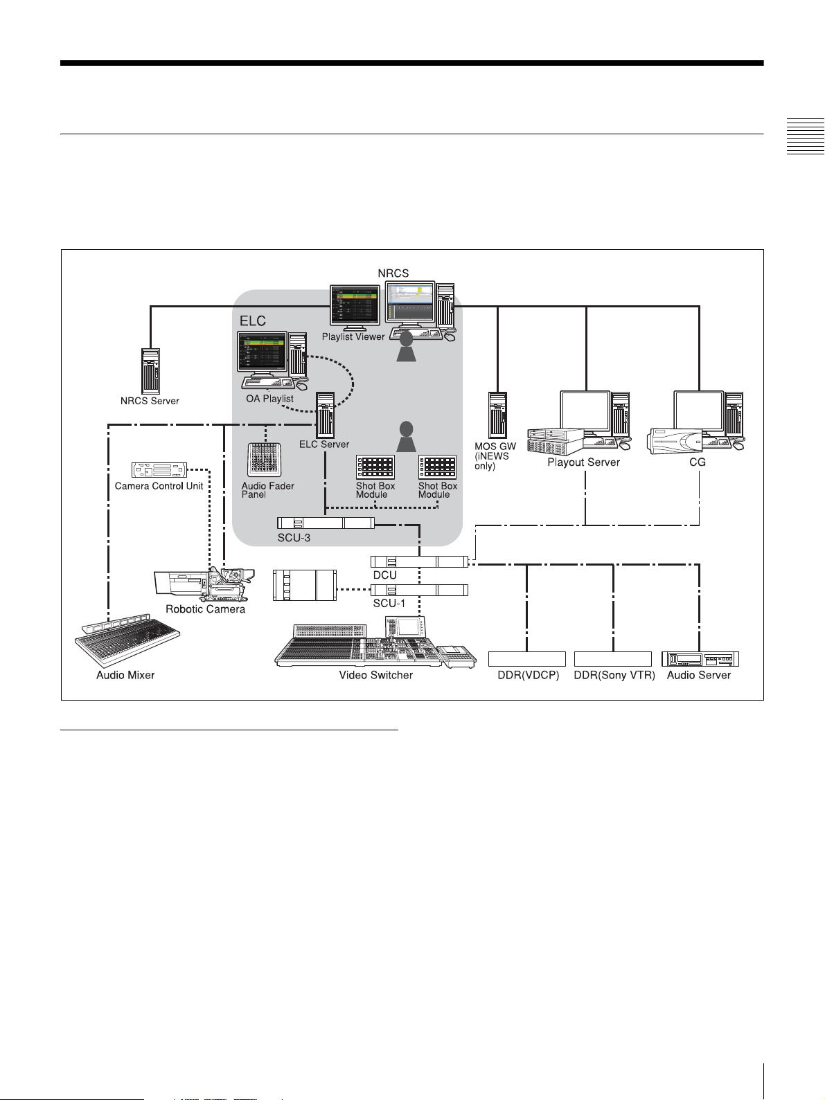
Basic System Configuration
The ELC-MVS01 Live Production Control Software
supports flexible NRCS-centric system configurations
with an MVS-8000 system, audio mixer, robotic camera,
audio server, playout server, CG and other devices.
Chapter 1 Overview
The following illustration shows an example image of the
basic system configuration with the NRCS.
Equipment to be Used in the System
This section explains major devices to be used with the
ELC-MVS01 Live Production Control Software system:
Devices required for ELC-MVS01 control
(Shown on a gray background in the
system configuration diagram)
• Shot Box Module
The shot box module is used for allocating a variety of
manual operations to its 96 operation buttons. This
module is required when you forward an ELC playlist
with the TAKE button, or inserting or deleting the DSK.
Up to two modules can be connected, each module can
be assigned to identical or different function tables.
• Audio Fader Panel
The audio fader panel allows you to associate a total of
16 audio mixer channels with its eight faders, and to
adjust audio levels, change PFL(Cue) and Mix-minus
settings, and turn the channels on and off.
Its front eight faders automatically change their
assignment settings and adjust audio levels according to
the process in a playlist. For the back eight faders, the
assignments are fixed and audio levels should be
adjusted manually.
System Configurations
13
Page 14

Devices under ELC-MVS01’s control
(Connected with black dash-dot lines in
the system configuration diagram)
The following devices perform on-air operations
according to the ELC playlist under the ELC-MVS01’s
Chapter 1 Overview
control:
• Video Switcher
The switcher uses an M/E for OA video effects and
another M/E for NEXT video effects, and uses PGM/
PST to switch OA and NEXT video signals.
It controls Keys manually or automatically according to
the ELC-MVS01’s settings, and controls the DSK
manually. The ELC-MVS01 does not make the DSK
settings, but it uses the settings (Initial Snapshot)
automatically loaded when the OA Playlist application is
started.
• DDR (VDCP)
The DDR (VDCP) is a disk recorder that the ELCMVS01 can control with VDCP (Video Disk Control
Protocol). You should register and list necessary video
files to be used in the ELC-MVS01 in advance by using
the Initial Setup application.
• DDR (SonyVTR)
The DDR (SonyVTR) is a disk recorder that the ELCMVS01 can control with Sony VTR Protocol. You can
use the desired video materials in the recorder by
specifying the IN point.
• Audio Server
You should register and list necessary audio files to be
used in the ELC-MVS01 in advance by using the Initial
Setup application. While preparing a cue, you can
specify the file names in the list.
• Studio Monitor
The ELC-MVS01 controls images output to the studio
monitors that are connected to the AUX buses of the
video switcher.
Devices beyond ELC-MVS01’s control
(Connected with black solid lines in the
system configuration diagram)
The following devices usually interface to NRCS and get
Rundown. They have their own playlist creation functions.
A change in the NRCS rundown is directly reflected, while
changes in the ELC playlist in the OA Playlist application
will not be reflected and manual changes are required. To
control manual operation, you need the control panel
supplied with each device.
• CG (Character Generator)
CG is the server of CG or still images. After receiving
Off from the Tally of the switcher, it prepares the next
materials.
• Playout Server
The playout server is an audio and video server that
contains daily-changing materials. The server receives a
GPI from the ELC-MVS01, and plays the materials.
Usually, the ELC-MVS01 does not specify files or make
channel settings, which are specified or made in the
NRCS system, but specifying a specific channel to be
used is also possible.
• Robotic Camera
The ELC-MVS01 recalls the shots of the robotic camera.
Since manual control from the ELC-MVS01 is not
available, the controllers supplied with the robotic
camera system is to be used.
• Audio Mixer
The ELC-MVS01 controls the audio levels, Ch On/Off,
changes in Mix-minus settings, and the function of the
audio mixer, automatically. Use of the audio fader panel
enables manual control of audio channels for 16 faders.
Depending on the type of input signals, there are two
types of audio mixers:
- Stereo fader mixer: handles stereo signals for each
input channel fader. This type of mixer is referred to as
a “stereo fader mixer” in this manual.
- Mono fader mixer: handles monaural signals for each
input channel fader. This type of mixer is referred to as
a “mono fader mixer” in this manual.
14
System Configurations
Page 15
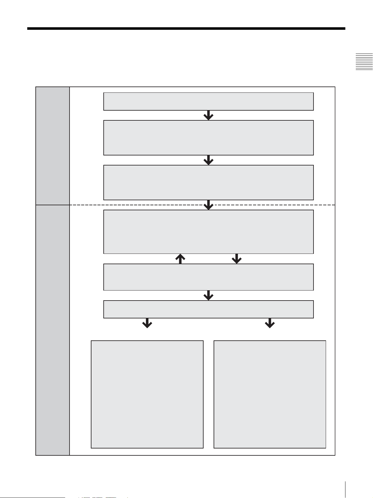
Basic Operation Flow
The following flowchart shows an example of the
operations when the system is installed.
• Making Initial Setup (page 50)
• Creating Icons (page 90)
• Creating Categories (page 102)
• Creating Cues (page 118)
• Editing Cues (page 132)
Preparations and Initial Settings
(for Technical Directors)
• Creating a Playlist (iNEWS:page 169 /ENPS: page 180 /
Without NRCS: page 188)
Chapter 1 Overview
Frequently-used manual operations
• Toggling the Duration Between Fixed/
Unfixed (page 208)
• Changing the Playlist Order (page 210)
• Controlling Downstream Keys
Playlist Creation and On-Air Operations
(for ELC Operators)
(page 212)
• Controlling Keys (page 214)
• Adjusting Audio Level (page 215)
• Changing the Side Flag Settings
(page 206)
• Editing Cues in the OA Playlist or
Playlist Viewer Window (page 220)
• Viewing a Playlist (iNEWS:page 176 /ENPS: page 184)
• Editing Cues (iNEWS:page 174 /ENPS: page 182 /
Without NRCS: page 195)
• Playing out a Playlist (page 201)
Advanced or occasional manual operations
• Switching Multiple Snapshots
Manually (page 222)
• Switching Video Manually (page 224)
• Outputting GPI Trigger Pulses (page 226)
• Getting Cues that are Not on the
Playlist to the Air (page 227)
• Enabling/Disabling Camera or Audio
Mixer Control (page 229, page 230)
• Overriding the Transition Settings for
the NEXT Cue (page 231)
• Switching a Video or Audio Device to
Its Backup (page 232, page 233)
Basic Operation Flow
15
Page 16
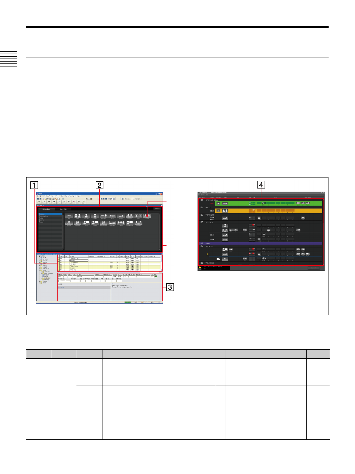
Overview of Playlist Creation
Playlist Creation Flow
Chapter 1 Overview
The ELC-MVS01 provides the ELC Plug-in application
for the NRCS client software to create a playlist, and the
Playlist Viewer application to view the created playlist.
The images below show how an ELC operator uses both
applications to create a rundown and view a playlist in a
news room.
You can create a playlist easily by adding a cue from the
Quick Cue of the ELC Plug-in to the NRCS client window
as an ELC object, which is called “Production cue” for
iNEWS and “Item” for ENPS.
When using iNEWS
ELC Plug-in
(Quick Cue)
Whether you use iNEWS or ENPS as an NRCS, the
windows and playlist creation operations differ. See either
of the sections below according to your NRCS type.
In addition to the ELC Plug-in application, the ELCMVS01 also provides the Playlist Viewer application that
enables you to create and edit playlists.
For details, see “Creating a Playlist without Using
NRCS” on page 186.
Cue
Each icon
represents a
cue, i.e.,
frequentlyused scenes.
iNEWS
A playlist can be created, viewed, and played out as
follows:
Location
Newsroom
Purpose Operator Operations in the iNEWS window Display in the ELC Playlist
Creating
a news
program
Producer A Create a rundown (baseline of a program)
using the iNEWS client. (Conventional
operation)
. Rundown is created.
ELC
Operator
B Add a cue in the Quick Cue of the ELC
Plug-in to the iNEWS rundown as a
3
production cue with a drag-and-drop
operation.
C Assign channels for CG or playout server
for the iNEWS client. Then save the
rundown.(Conventional operation)
ELC Playlist
For ELC production cue settings, see “Rules in setting
ELC production cues” on page 171.
Ref.page
At this time, there are no ELC
b
settings made for the rundown.
. Playlist is not created.
D Production cues with the
same page number make an
ELC story. Cues appear in a
playlist.
. Playlist is created.
b
page
169
page
171
16
Overview of Playlist Creation
Page 17
Location
Control
Sub
room
Purpose Operator Operations in the iNEWS window Display in the ELC Playlist
On the
air
Producer Change the rundown order in the iNEWS
ELC
Operator
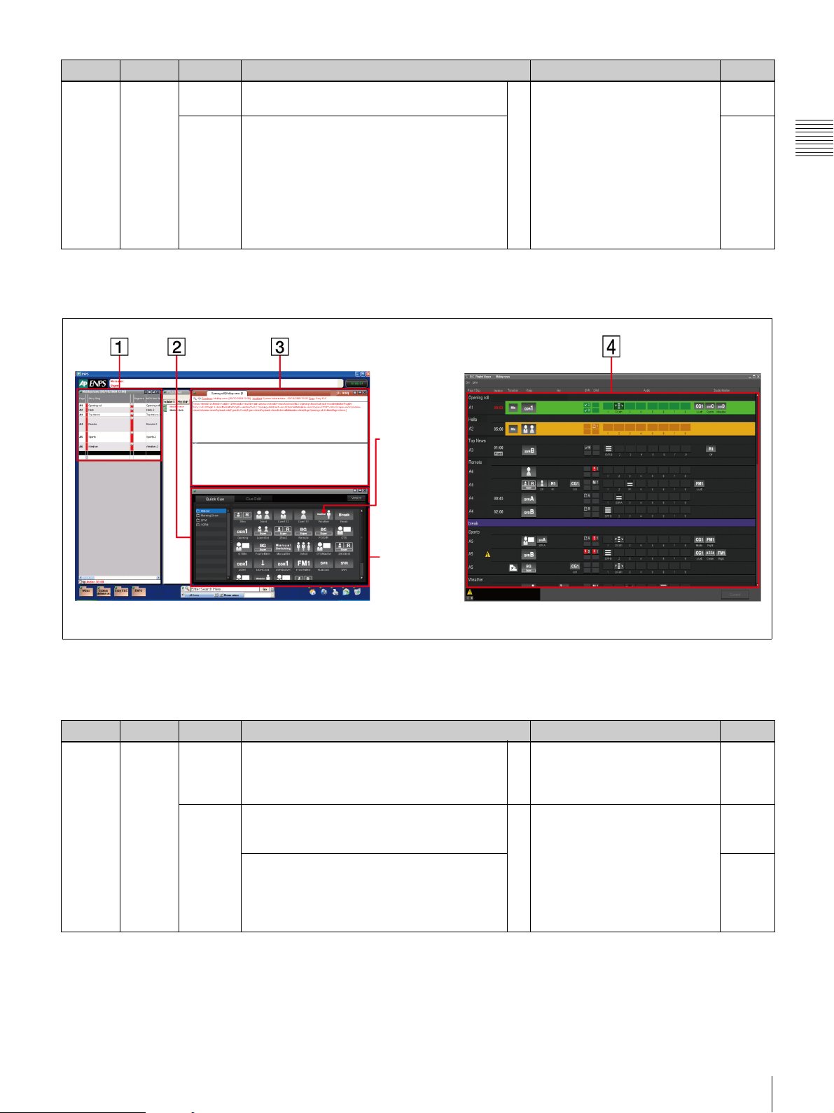
When using ENPS
client. (Conventional operation)
• Add a production cue or edit cues even
while on the air (except for the OA Cue).
• Change the channel assigned for the CG or
playout server for the iNEWS client.
(Conventional operation)
• Skip stories on the rundown separately on
the iNEWS client, on each device, or in the
ELC Plug-in application.(Conventional
operation)
Cue
Each icon
represents a
cue, i.e.,
frequentlyused scenes.
Changes in the rundown will be
reflected.
b
Ref.page
page
174
pages
14, 171
page 14
Chapter 1 Overview
ENPS
A playlist can be created, viewed, and played out as
follows:
Location
Newsroom
Purpose Operator Operations in the ENPS window Display in the ELC Playlist
Creating
a news
program
Producer A Create a rundown (baseline of a program)
using the ENPS client. (Conventional
operation)
. Rundown is created.
ELC
Operator
B Add a cue in the Quick Cue of the ELC
Plug-in to the ENPS rundown as an Item
3
with a drag-and-drop operation.
A Assign channels for CG or playout server
for the ENPS client. Then save the
rundown. (Conventional operation)
ELC Plug-in
(Quick Cue)
For ELC production cue settings, see “Rules in setting
ELC items” on page 182.
ELC Playlist
At this time, there are no ELC
b
settings made for the rundown.
. Playlist is not created.
D Items with the same Slug
make an ELC story. Cues
appear in a playlist.
. Playlist is created.
b
Ref.page
page
180
Overview of Playlist Creation
17
Page 18
Location
Control
Sub
room
Chapter 1 Overview
Purpose Operator Operations in the ENPS window Display in the ELC Playlist
On the
air
Producer Changing the rundown order in the ENPS
client. (Conventional operation)
ELC
Operator
• Add an Item or edit cues even while on the air
(except for the OA Cue).
• Change the channel assigned for the CG or
playout server for the ENPS client.
(Conventional operation)
• Skip stories on the rundown separately on
the ENPS client, on each device, or in the
ELC Plug-in application.(Conventional
operation)
When not using NRCS
A playlist can be created from scratch and edited in the
Playlist Viewer window without using NRCS. It can be
used for playout operation, too, as follows:
Changes in the rundown will be
reflected.
b
Ref.page
page
182
pages
14, 182
page 14
Location
Newsroom
Control
Sub
room
Purpose Operator Operations
Creating
a news
program
On the
air
Producer
or ELC
Operator
Producer
or ELC
Operator
Create a playlist using the Playlist Viewer application by adding cues prepared in the
Quick Cue window, and editing cues.
. Playlist is created.
On-air operations using the OA Playlist application.
Even while the playlist is being used for on-air operation, the both Playlist Viewer
application in the full-edit mode and the OA Playlist application allow you the
following operations, respectively. (The OA Cue cannot be edited or deleted though.)
• The Playlist Viewer application allows editing, adding, deleting, and moving of a
cue, as well as editing, adding, deleting, and moving of a story.
• The OA Playlist application allows editing of a cue.
Ref.page
page
186
page
201
page
191
page
220
18
Overview of Playlist Creation
Page 19
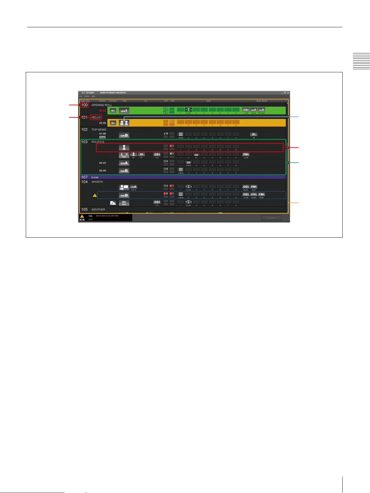
Elements of a Playlist
This section explains the elements of a playlist. The
following shows the relationship between an Icon, a cue, a
story, and a playlist in the Playlist Viewer application:
Page
Slug
Chapter 1 Overview
Icon
Cue
ELC Story
Playlist
Icon
An Icon is a graphic representing settings of a video
switcher, audio mixer, and devices for materials including
cameras, servers, and CG.
There are the following four types of Icons:
• Video Icon
A Video Icon represents video materials from the
camera, playout server, CG, and DDR.
• Audio Icon
An Audio Icon represents audio materials from an audio
server, or video server.
• Transition Icon
A Transition Icon represents a transition setting.
• Effect Icon
An Effect Icon represents a setting of compound video
effects.
Cue
A cue is composed of Icons and their detailed settings. It is
the minimum unit, a frequently-used scene, to be taken by
the TAKE button. A cue can be registered in advance in the
ELC Plug-in application or in the Quick Cue window of
the Playlist Viewer application. You can then easily set a
pre-registered cue in the playlist in the Playlist Viewer
window. You can also open the Cue Edit window from the
Playlist Viewer application and OA Playlist application,
and edit previously created cues.
ELC Story
An ELC Story definition differs between iNEWS and
ENPS:
• In iNEWS: A group of cues with the same NRCS Page
number is defined as an ELC story.
• In ENPS: A group of cues with the same NRCS Slug is
defined as an ELC story.
Playlist
A playlist is a list of ELC stories placed in the order to be
played out.
Overview of Playlist Creation
19
Page 20
Names and Functions of
Parts
Chapter 2 Names and Functions of Parts
Initial Setup Window
The Initial Setup application is designed for technical
directors to make required setup for routine operations
when a new program is planned or there is a change on a
device on a studio.
To open the Initial Setup main menu, double-click the
Initial Setup icon on the desktop. From the Initial Setup
Main Menu, you can select the following sub menus:
• Video Switcher Settings: It allows you to associate
a V/K pair number of the video switcher with an Icon.
• Audio Mixer Settings: It allows you to associate the
input fader number of the audio mixer with an Icon, and
specifies audio level options of the ELC-MVS01. It also
associates each fader number of the Audio Fader panel
with a device icon registered in the ELC-MVS01, so that
automatic or manual control from the ELC-MVS01
becomes enabled.
Chapter
• Shot Box Module Assign: It allows you to assign
functions to be used for manual on-air operations to the
buttons on the shot box module.
• DDR(VDCP) File List Creation: It allows you to
register the files of DDR(VDCP) to be used in the ELCMVS01 software.
• Audio Server File List Creation: It allows you to
register the files of the audio server to be used in the
ELC-MVS01 software.
• Studio Monitor Settings: It allows you to make the
settings required for the AUX buses for studio monitors.
You can also view the windows of the Initial Setup
application in the System Setup application.
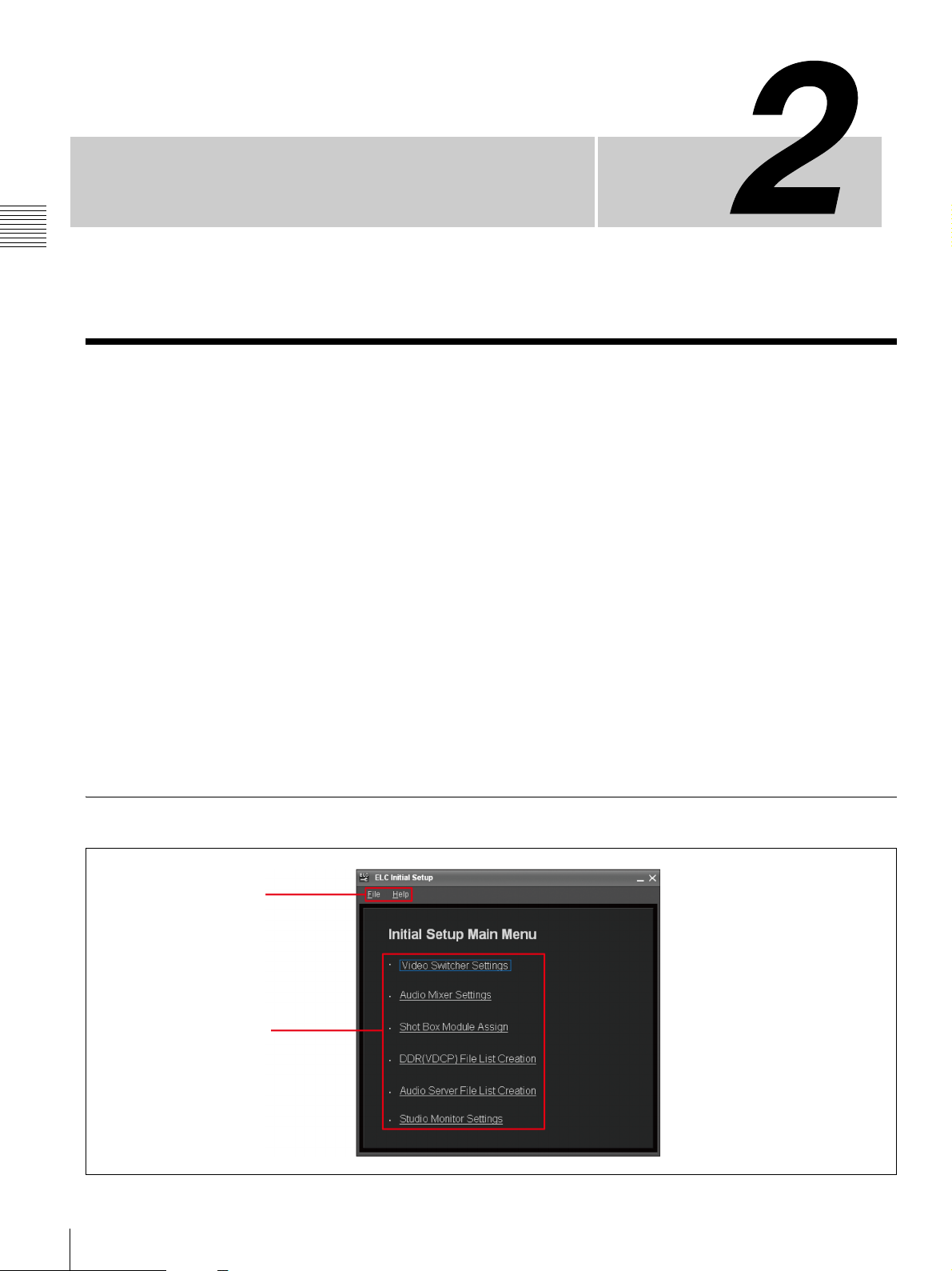
Initial Setup Main Menu
1 Menu bar
2 Sub menus
20
Initial Setup Window
Page 21
a Menu bar
The Menu bar provides menus for using the Initial Setup.
• File menu:
Exit: Exits the Initial Setup menu.
• Help menu:
Version: Displays the Initial Setup version number.
Help: Displays this User’s Guide.
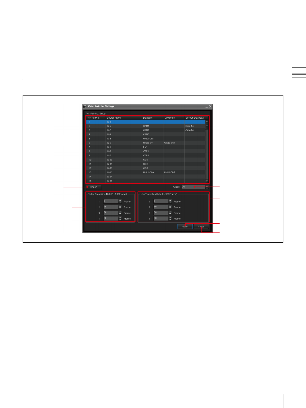
Video Switcher Settings Window
1 V/K Pair No. Setup
list
b Sub menus
Click the desired sub menu line to open the setting window
for the selected menu option.
For the Initial Setup Application, see “Starting the Initial
Setup Application” on page 51.
Chapter 2 Names and Functions of Parts
2 Import button
4 Video Transition
Rate Setting block
a V/K Pair No. Setup list
Allocate the V/K pair number of switcher to an ELCMVS01 Video Icon:
• V/K Pair No.: A fixed number between 1 to 128 is
displayed, which has been specified by the switcher.
• Source Name: The source name of the video specified
by the switcher is displayed in up to 16 alphanumeric
characters.
• Device(V): Select the device to be used for the video
signal, which corresponds to a V/K pair number, to be
displayed in the selected Class.
• Device(K): Select the device to be used for the key
signal.
This setting is for a DDR(VDCP) device only, and is not
necessary when the device for video and the device for
the key signal are identical.
• Backup Device(V): Select the backup device for
Device(V).
3 Class drop-down list
box
5 Key Transition Rate
Setting block
6 Save button
7 Close button
b Import button
Press this button to import the source names of the video
signals from the switcher.
c Class drop-down list box
Select the desired class to narrow down the devices to be
displayed for the selected line on the list, since devices are
classified into classes.
d Video Transition Rate Setting block
Select an option for the video transition rate to be
displayed in the Cue Edit window.
e Key Transition Rate Setting block
Select an option for the key transition rate to be displayed
in the Cue Edit window.
f Save button
Press this button to save the settings.
Initial Setup Window
21
Page 22
g Close button
Press this button to close the Video Switcher Settings
window.
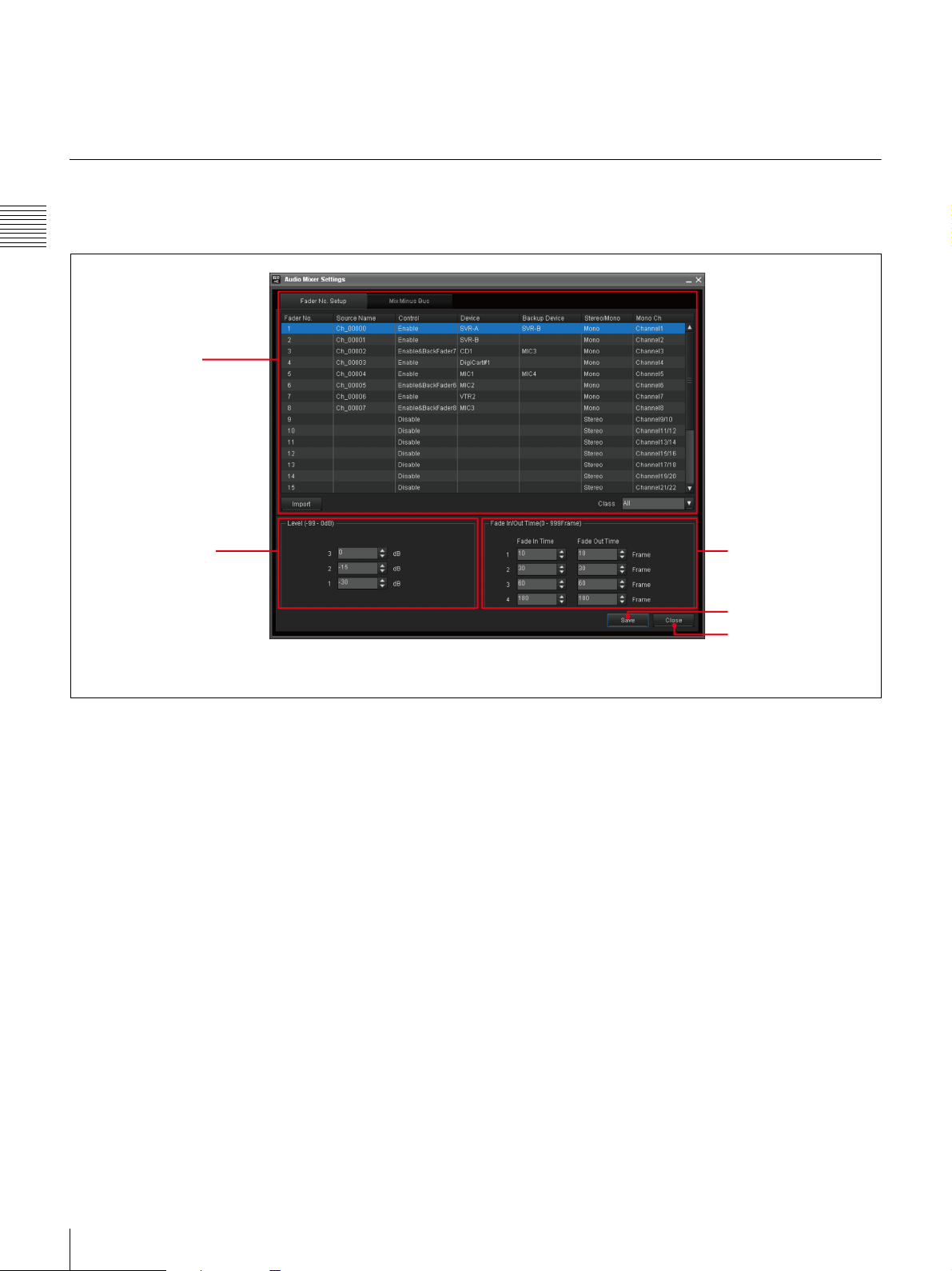
Audio Mixer Settings Window
For the settings on the Video Switcher Settings window,
see “Making the Video Switcher Settings” on page 53.
There are two tabs in the Audio Mixer Settings window:
the Fader No. Setup tab and the Mix-Minus Bus tab.
Chapter 2 Names and Functions of Parts
1 Fader No. Setup
/ Mix-Minus Bus
tabs
2 Audio Level Setting
block
The Audio Level setting block, Fade IN/Out Time Setting
block, Save and Close buttons are shared by the two tabs.
3 Fade In/Out Time
Setting block
4 Save button
5 Close button
22
Initial Setup Window
Page 23
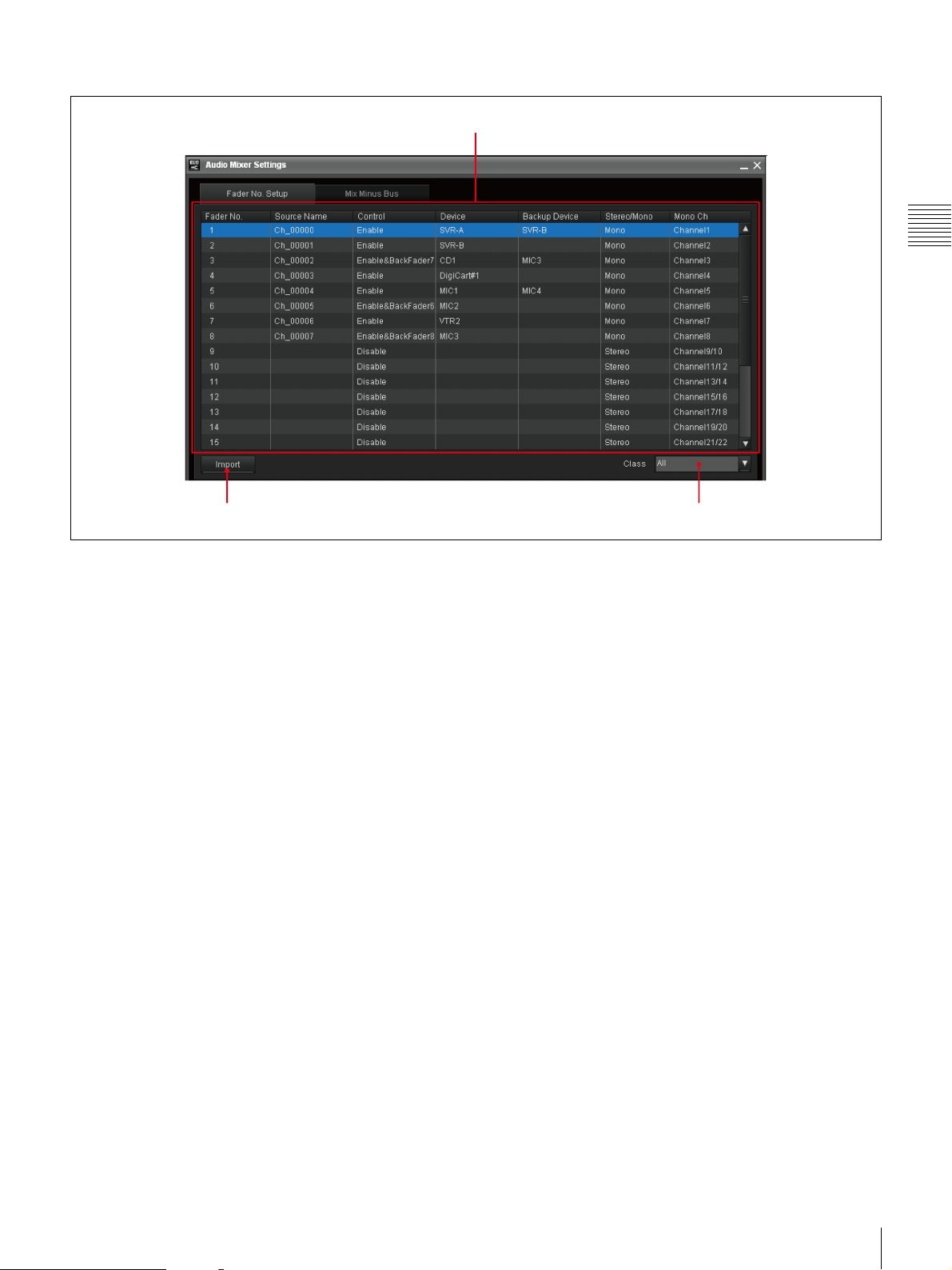
a Fader No. Setup tab/Mix-Minus Bus tab
Fader No. Setup tab
2 Import button
1 Fader No. setup list
1 Fader No. setup list
Depending on the type of the audio mixer used, either, a
stereo fader mixer or a mono fader mixer, the contents of
the window differ.
This list is used to allocate the input Fader number of the
audio mixer to an Audio Icon:
• Fader No.: A fader number of an audio mixer panel is
displayed according to the Device Setup settings of the
System Setup application.
For a mono fader mixer, the fader number displayed in
this column may differ from that displayed on the audio
mixer panel.
• Source Name: The source name of the audio input
specified with the mixer is displayed in up to eight
alphanumeric characters.
When a mono fader mixer is being used and the fader is
paired, the source name for the odd fader number is
displayed.
When an audio mixer that does not allow you to import
the source names specified on it is used, you can enter
source names of up to eight alphanumeric characters in
this window.
• Control: Enable or disable automatic or manual fader
control from the ELC-MVS01 system. (Including
assignment of an Audio Icon to the audio fader panel.)
• Device: Select the device in the selected Class
corresponding to the input Fader number.
• Backup Device: Select the backup device in the
selected Class corresponding to the input Fader number.
Chapter 2 Names and Functions of Parts
3 Class drop-down list box
• Stereo/Mono*: Displays the Device Setup settings of
the System Setup application for how the fader is
controlled, in stereo or monaural:
Stereo: The fader is paired and controlled in stereo.
Mono: The fader is used and controlled monaurally.
• MonoCh*: Displays the channels actually controlled
according to the Stereo/Mono setting of the Device
Setup of the System Setup application.
* Displayed only when a mono fader mixer is being used.
2 Import button
Press this button to import the source name of the input
audio from the audio mixer.
3 Class drop-down list box
Select the desired class to narrow down the devices to be
displayed for the selected line on the list, since devices are
classified into classes.
Initial Setup Window
23
Page 24
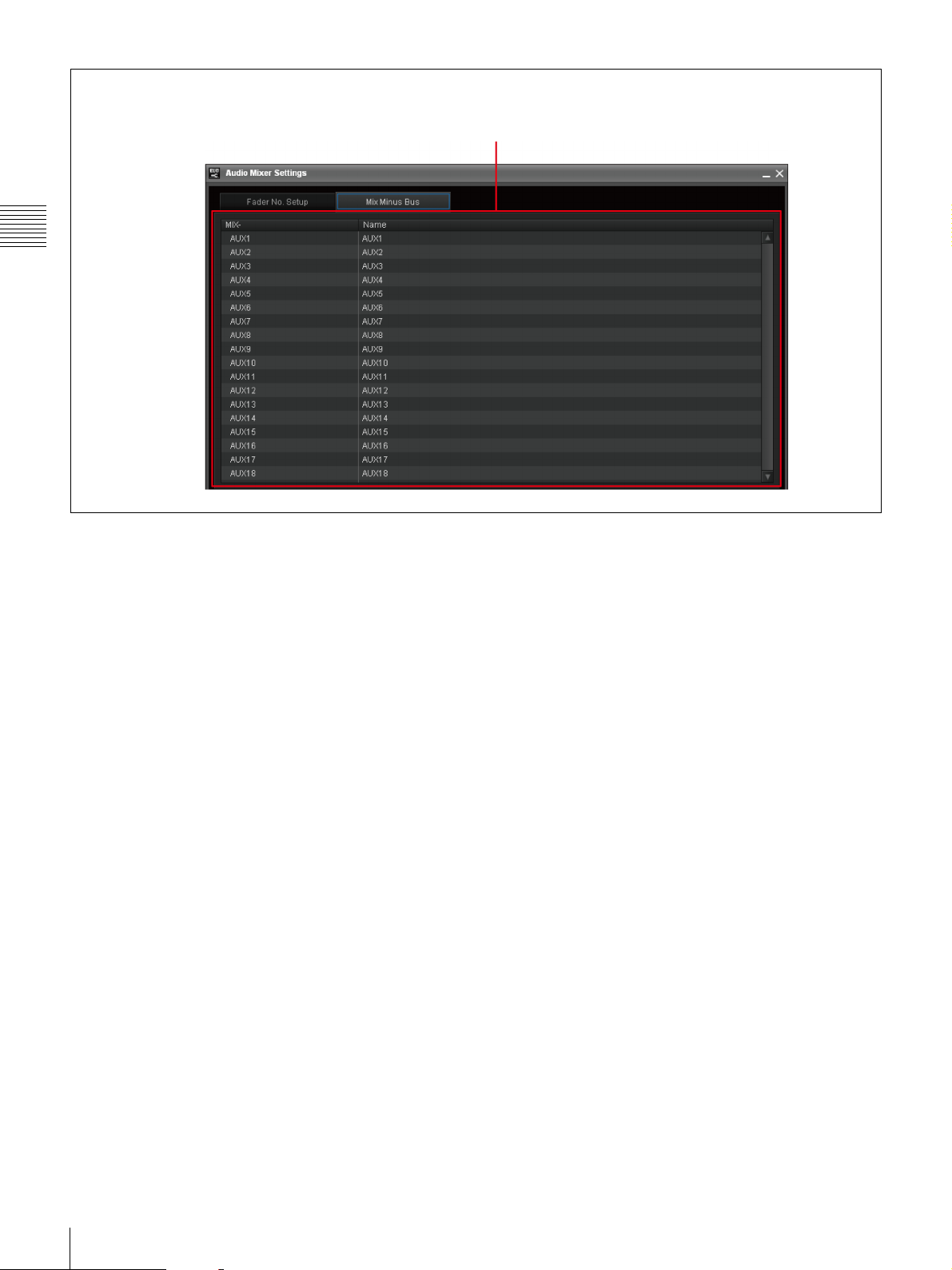
Mix-Minus Bus tab
Chapter 2 Names and Functions of Parts
1 Mix-minus bus list
1 Mix-minus bus list
The name of each AUX bus of the audio mixer is
displayed. You can rename it in up to eight alphanumeric
characters.
b Audio Level Setting block
Set the Audio Level options to be displayed in the Cue Edit
window.
c Fade In/Out Time Setting block
Set the Fade In/Out Time options to be displayed in the
Cue Edit window.
d Save button
Press this button to save the settings.
e Close button
Press this button to close the Audio Mixer Settings
window.
For the settings on the Audio Mixer Settings window, see
“Making the Audio Mixer Settings” on page 57.
24
Initial Setup Window
Page 25
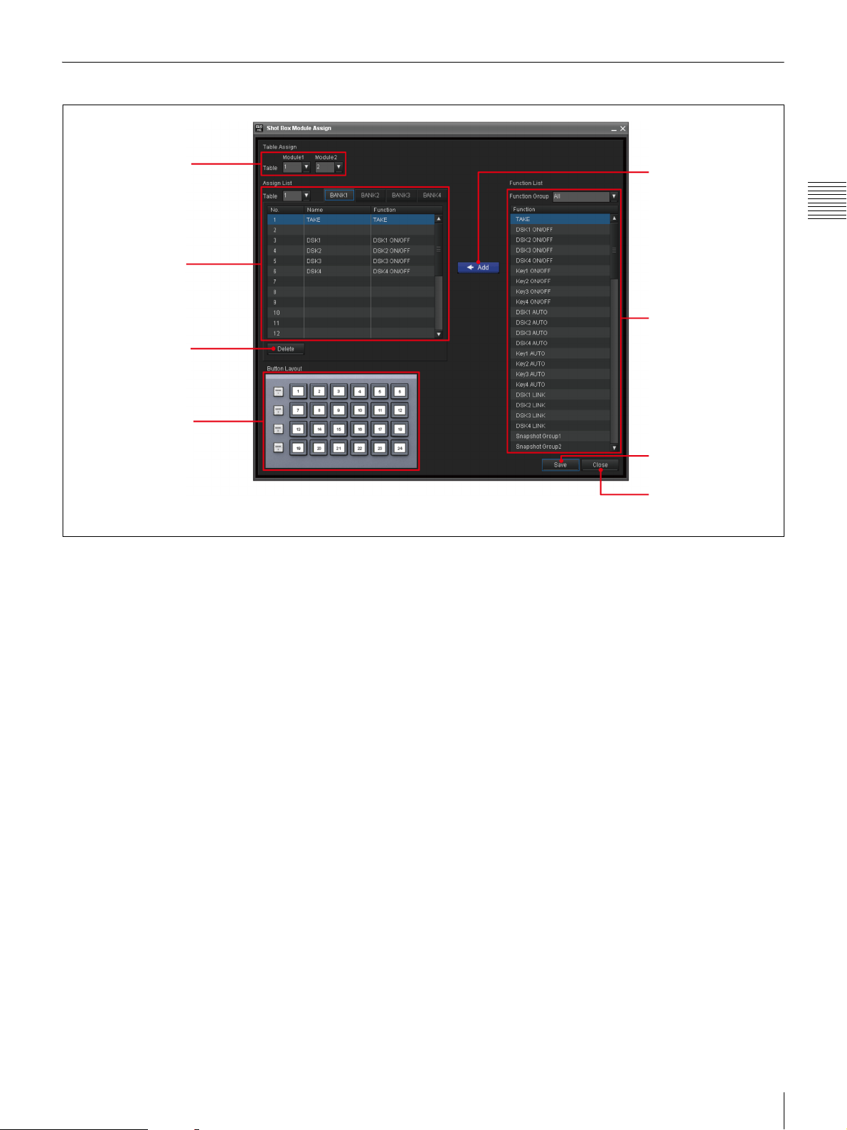
Shot Box Module Assign Window
1 Table Assign
2 Assign List
3 Delete button
4 Button Layout
a Table Assign
Select the table to be assigned to the shot box module.
When there are two modules, the modules can be assigned
to the identical or different tables.
5
CADD button
6 Function List
7 Save button
8 Close button
d Button Layout
The button layout of the shot box module is displayed, to
help you identify the location of the button specified in the
“No.” column of the Assign List.
Chapter 2 Names and Functions of Parts
b Assign List
The list of functions assignment to buttons on the shot box
module is displayed.
• Table No.: The number of the table on which the
functions are assigned to the shot box module buttons.
• BANK 1 to 4 tabs: Select the desired BANK tab
corresponding to the BANK button on the shot box
module.
• No.: The button number for the selected BANK on the
shot box module to which the function is assigned.
• Name: The name of the assigned function, which is
displayed on the relevant button on the shot box module.
You can rename it in up to eight alphanumeric characters
by clicking the relevant column.
• Function: The function assigned on the button is
displayed.
c Delete button
Press this button to delete the selected function from the
Assign List.
e C ADD button
Press this button to add the selected function of the
Function List to the Assign List.
f Function List
Select the function that you want to assign to a button on
the shot box module.
Functions are grouped. Select the desired group using the
Function Group drop-down list box to narrow down the
functions to be displayed.
g Save button
Press this button to save the settings.
h Close button
Press this button to close the Shot Box Module Assign
window.
For the settings on the Shot Box Module Assign window,
see “Assigning Functions to the Shot Box Module
Buttons” on page 65.
Initial Setup Window
25
Page 26
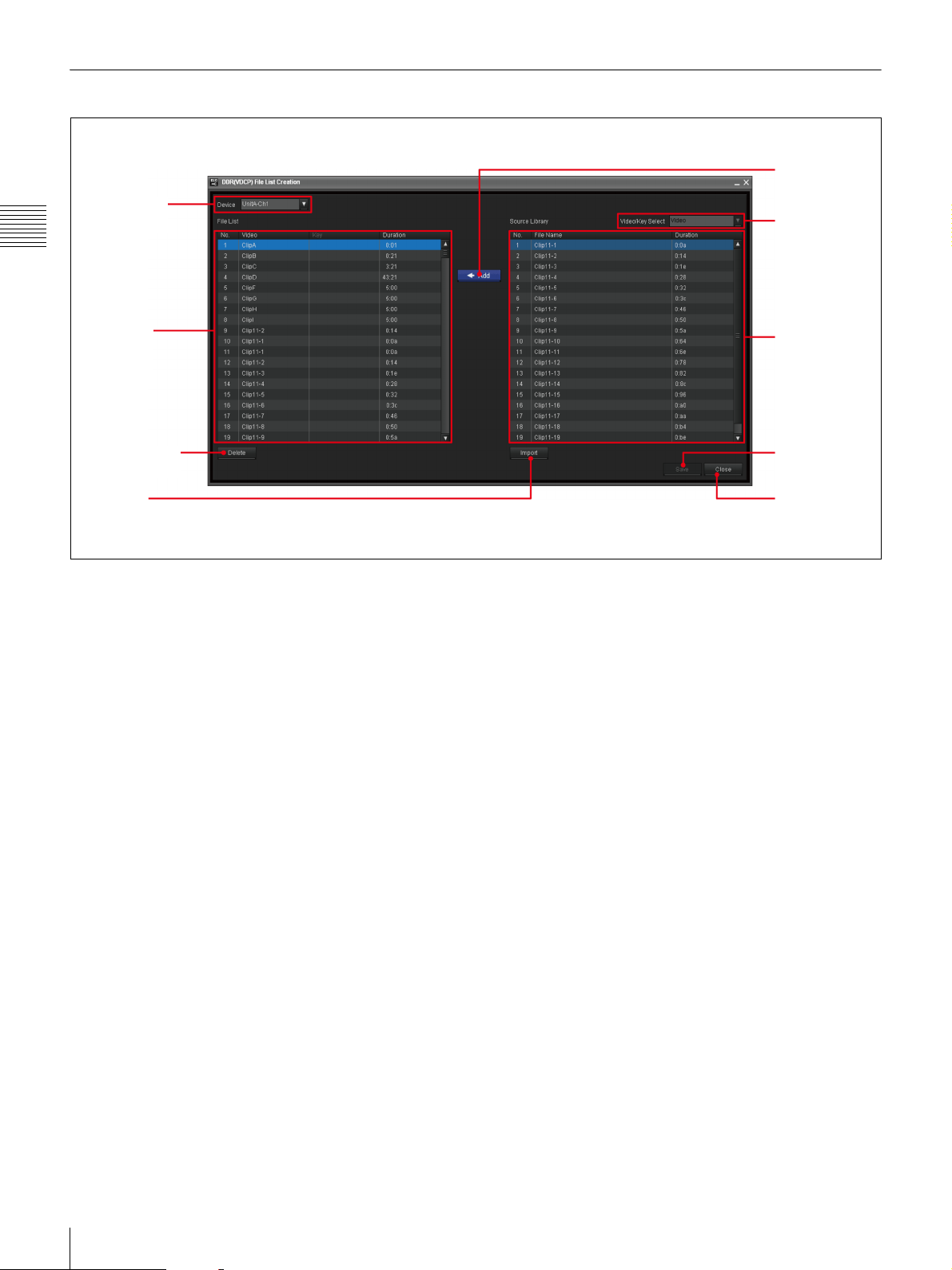
DDR(VDCP) File List Creation Window
1 Device box
Chapter 2 Names and Functions of Parts
CADD button
5
6 Video/Key
Select box
2 File List
3Delete button
4 Import
button
a Device box
Select the desired DDR(VDCP) device for which you
would like to create a file list.
b File List
A list of files added from the DDR(VDCP) which are
ready for use with the ELC-MVS01 is displayed.
• No.: Series numbers of the added files.
• Video: The name, up to 23 alphanumeric characters of
the video file stored on the DDR(VDCP).
• Key: The name, up to 23 alphanumeric characters of the
key file stored on the DDR(VDCP).
• Duration: The length of the file stored on the
DDR(VDCP) in HH:MM:SS:FF.
c Delete button
Press this button to delete the selected file from the File
List.
d Import button
Press this button to import the File Name and Duration
information of the files from the DDR(VDCP).
e C ADD button
Press this button to add the selected file of the Source
Library to the File List.
f Video/Key Select box
Select Video or Key to switch the display on the Source
Library when using key files from a different device (unit/
channel) from the device used for video files.
7 Source Library
8 Save button
9 Close button
The device for the key files should be specified in the
Video Switcher Settings window in advance.
g Source Library
The files stored on the device selected in the Device box
and to be added to the File List are displayed. The
displayed files differ, depending on the selection in the
Video/Key Select box.
• No.: Series numbers of the files stored in the
DDR(VDCP).
• File Name: The name, up to 23 alphanumeric
characters of the file stored on the DDR(VDCP).
• Duration: The length of the file stored on the
DDR(VDCP) in HH:MM:SS:FF.
For a device that is controlled by the simple VDCP,
however, the durations are not displayed.
Select the line of the file you want to add to the File List.
h Save button
Press this button to save the settings.
i Close button
Press this button to close the DDR(VDCP) File List
Creation window.
For the settings on the DDR(VDCP) File List Creation
window, see “Managing Video Material - Creating the
DDR(VDCP) File List” on page 73.
26
Initial Setup Window
Page 27
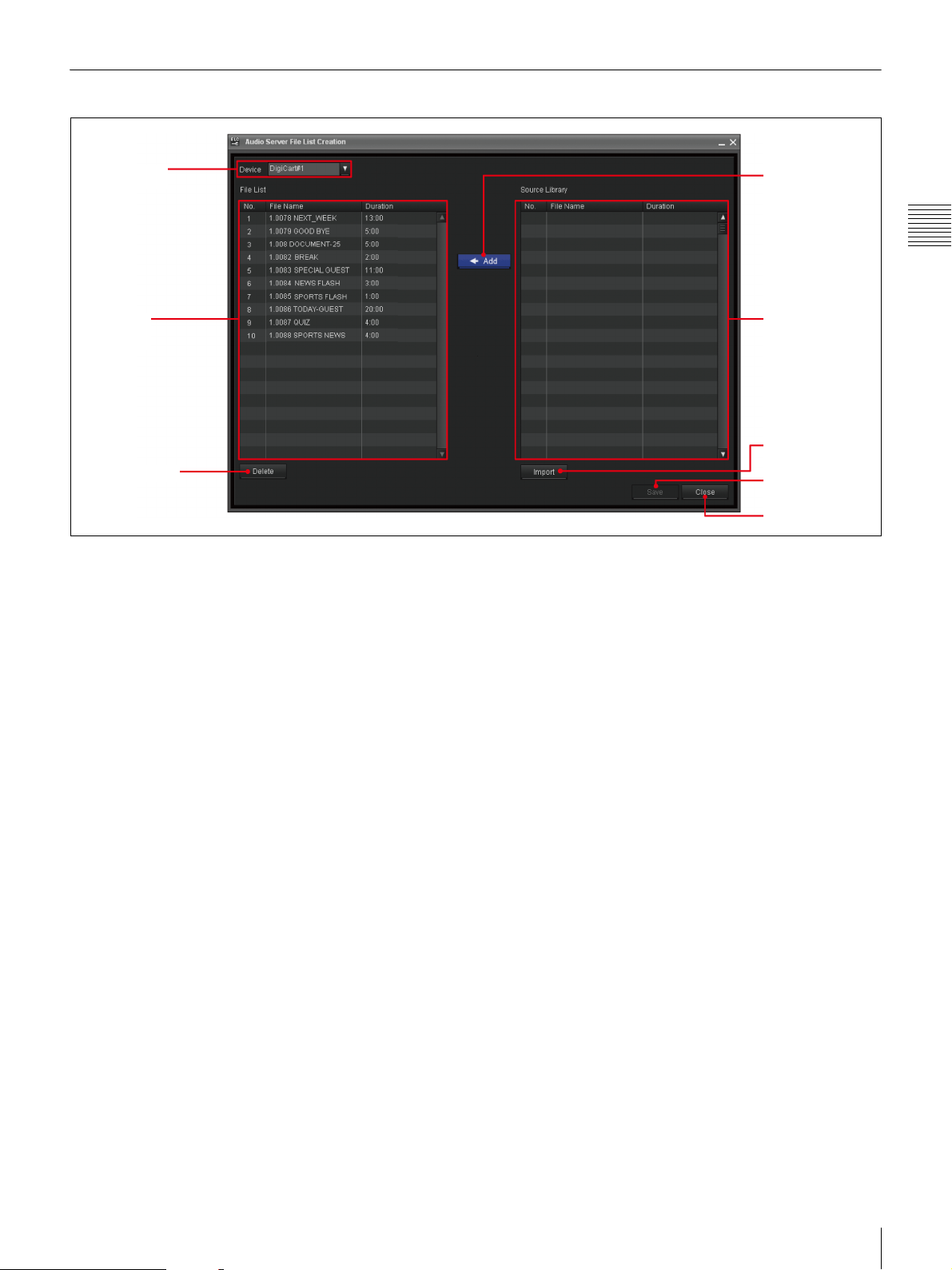
Audio Server File List Creation Window
1 Device box
2 File List
3Delete button
a Device box
Select the desired device for which you would like to
create a file list, so that the files will be displayed both in
the File List and the Source Library.
b File List
Displays the list of files added from the audio server which
are ready for use with the ELC-MVS01.
• No.: Series numbers of the added files.
• File Name: The name, up to 23 alphanumeric
characters of the file stored on the audio server.
• Duration: The length of the file stored on the audio
server in HH:MM:SS:FF.
c Delete button
Press this button to delete the selected file from the File
List.
CADD button
4
5 Source Library
6 Import button
7 Save button
8 Close button
f Import button
Press this button to import the File Name and Duration
information of the files from the audio server.
g Save button
Press this button to save the settings.
h Close button
Press this button to close the Audio Server File List
Creation window.
For the settings on the Audio Server File List Creation
window, see “Managing Audio Material - Creating the
Audio Server File List” on page 77.
Chapter 2 Names and Functions of Parts
d C ADD button
Press this button to add the selected file of the Source
Library to the File List.
e Source Library
The files stored on the audio server are displayed.
• No.: Series numbers of the files stored in the audio
server.
• File Name: The name, up to 23 alphanumeric
characters of the file stored on the audio server.
• Duration: The length of the file stored on the audio
server in HH:MM:SS:FF.
Select the line of the file you want to add to the File List.
Initial Setup Window
27
Page 28
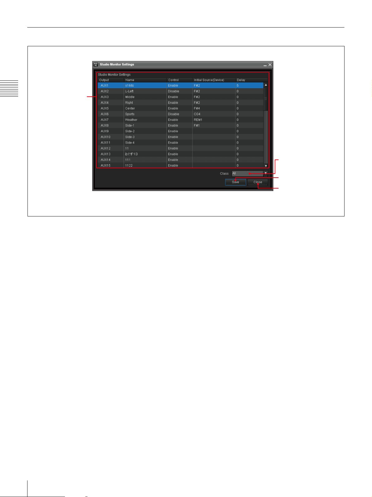
Studio Monitor Settings Window
Chapter 2 Names and Functions of Parts
1 AUX bus setup list
a AUX bus setup list
The list of AUX buses of the switcher and the settings for
the respective buses is displayed. The AUX buses are used
for output signals to the studio monitors.
• Output: A fixed AUX bus number for the switcher
between AUX 1 to AUX 48 is displayed.
• Name: The name of the studio monitor connected to the
AUX bus, which is displayed in the Cue Edit window.
You can rename it in up to eight alphanumeric characters
by clicking the relevant column.
• Control: Enable or disable control of the AUX bus
from the ELC-MVS01 software.
• Initial Source (Device): Select the desired device so
that the video from that device will be displayed on the
corresponding studio monitor when no Video icon is
specified for it.
• Delay: Specify the delayed value between 0 to 99
frames, when there is a delay in performing the operation
after the device accepted a command from the ELCMVS01 software.
2 Class drop-down list
box
3 Save button
4 Close button
d Close button
Press this button to close the Studio Monitor Settings
window.
For the settings available on the Studio Monitor Settings
window, see “Making the Studio Monitor Settings” on
page 80.
b Class drop-down list box
Select the desired class to narrow down the devices to be
displayed for the Initial Source (Device) on the selected
line of the list, since devices are classified into classes.
c Save button
Press this button to save the settings.
28
Initial Setup Window
Page 29
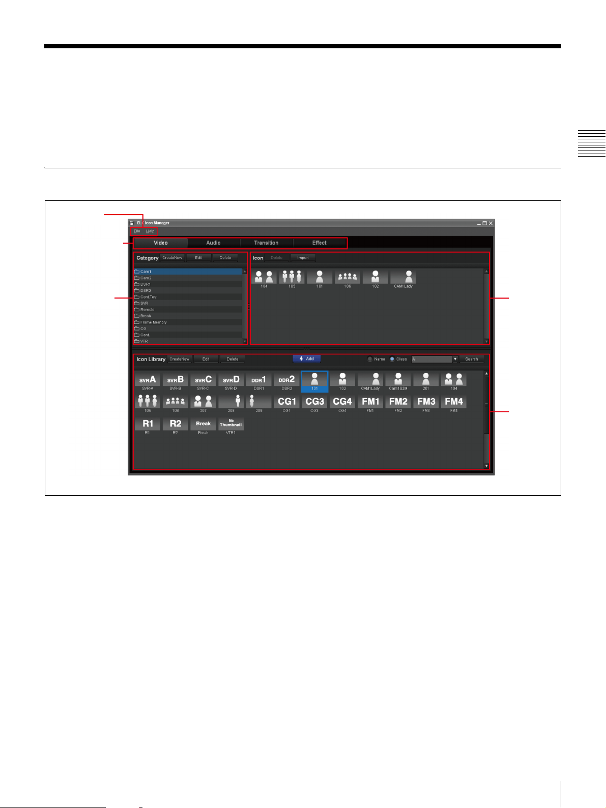
Icon Manager Window
The Icon Manager application is designed for ELC
operator create an Icon, symbolizing frequently-used
settings of a video switcher, audio mixer, or other device,
so that you can use them to register a cue. There are four
Icon Manager Main Window
1 Menu bar
2 Icon types tabs
1 Category list
types of Icons: Video, Audio, Transition, and Effect. The
created Icons are then saved in the relevant category.
To open the Icon Manager window, double-click the Icon
Manager icon on the desktop.
Chapter 2 Names and Functions of Parts
2 Icon list
a Menu bar
The Menu bar provides menus for using the Icon Manager:
• File menu:
Exit: Exits the Icon Manager menu.
• Help menu:
Version: Displays the Icon Manager version number.
Help: Displays this User’s Guide.
b Icon types tabs
Click the desired tab which stands for an Icon type you can
register in the ELC-MVS01: Video, Audio, Transition,
and Effect.
For the overview of Icons handled on the Icon Manager
Main window, see “Starting the Icon Manager
Application” on page 89.
3 Icon
Library
Icon Manager Window
29
Page 30
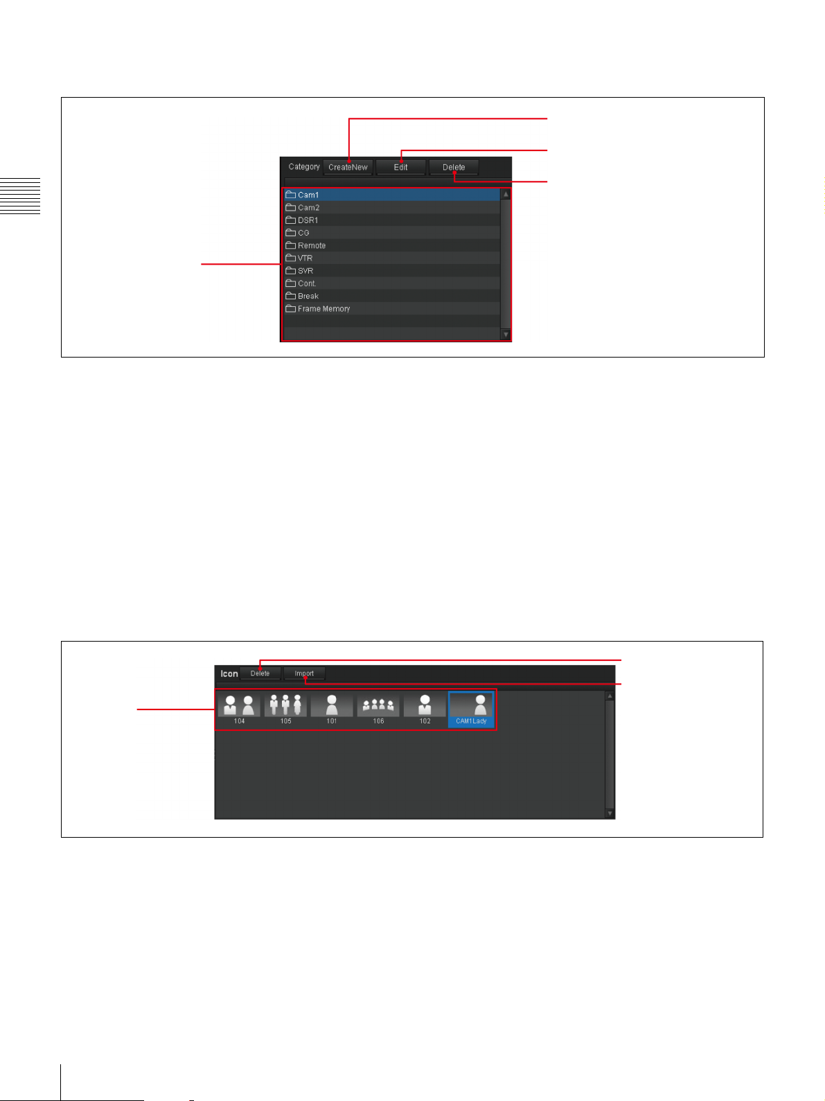
1 Category list
Chapter 2 Names and Functions of Parts
2 Create New button
3 Edit button
4 Delete button
1 Category list
a Category list
The system and user-defined categories are listed. Click
the desired category so that the relevant Icons are
displayed in the Icon list.
b Create New button
Click this button to display the Category window to create
a new category.
c Edit button
Click this button to display the Category window to edit
the selected category in the category list.
2 Icon list
1 Icon list
d Delete button
Click this button to delete the selected category in the
category list.
For details, see “Category Window” on page 37.
For the operations using the Category list, see “Managing
Categories” on page 102.
2 Delete button
3 Import button
a Icon list
Stores icons you register according to a category from the
Icon Library. Among the registered Icons, only the Icons
in the selected category in the Category list are displayed.
b Delete button
Click this button to delete the selected Icon in the Icon list
from the category.
30
Icon Manager Window
c Import button (On the Video tab only)
Click this button to open the Import from Camera Robotics
dialog box. This dialog box is used to import the “shots”
from robotic cameras as Video Icons of the selected
category.
For the operations using the Icon list, see “Registering an
Icon in a Category” on page 107, and “Importing Camera
Shots and Creating Icons” on page 110.
Page 31

3 Icon Library
3 Delete button
4 Edit button
5 Create New
button
6 Icon Library
a ADD button
Click this button to add the selected Icon in the Icon
Library to the Icon list of the selected category.
b Search block
Check the desired check box of either Name or Class, that
you want to use for searching for Icons. Then click
[Search] to search for Icons of the selected search option.
The Icons found are displayed in the Icon Library.
2 Search block1 ADD button
Chapter 2 Names and Functions of Parts
c Delete button
Click this button to delete the selected Icon in the Icon
Library.
d Edit button
Click this button to display the Audio, Video, Transition,
or Effect Icon window to edit the selected Icon in the Icon
Library.
e Create New button
Click this button to display the Audio, Video, Transition,
or Effect Icon window to create an Icon.
f Icon Library
Stores the icons that you create or locate.
All the icons belonging to the selected Icon type tab are
displayed.
For details, see “Video Icon Window” on page 32, “Audio
Icon Window” on page 33, “Transition Icon Window” on
page 34, or “Effect Icon Window” on page 35.
For the operations on the Icon list, see “Registering an
Icon in a Category” on page 107.
Icon Manager Window
31
Page 32

Video Icon Window
The Video Icon window allows you to create or edit a
Video Icon. To display the window, click [Create New] on
the Icon Library of the Video tab.
Chapter 2 Names and Functions of Parts
1 Icon preview
2 Icon property setting block
3 Camera Control block
4 OK/Cancel/Save/Save as
buttons
a Icon preview
Thumbnail and name of the created Video Icon is
displayed.
b Icon property setting block
Specify the following for a Video Icon:
• Icon Name: Input the desired Icon name in up to eight
alphanumeric characters.
• Thumbnail: Click [Ref.] to display an image list and
select the desired image for the thumbnail.
• Class: Select the desired class for a new Icon to narrow
down the devices to be displayed, since devices are
classified into classes.
• Device: Select the device according to the class you
select for a new Icon.
c Camera Control block
When you select an Icon whose class is Camera, specify
the following:
• Manual/Auto: Specify whether you control the camera
manually or automatically. When you check [Auto] the
following Show and Shot boxes become enabled.
• Show: According to the device you select, the
corresponding Shows are displayed. From among these
Shows, select the desired Show.
• Shot: According to the Show you select, the
corresponding Shots are displayed. From among these
Shots, select the desired Shot.
• Import: Click to recall the Show/Shot information.
d OK/Cancel/Save/Save as buttons
When you create a new Icon, OK and Cancel buttons are
displayed. When you edit an existing Icon, Save, Save as,
and Cancel buttons are displayed.
• OK: Adds the created Icon to the Icon Library.
• Cancel: Cancels the settings and returns to the Icon
Manager main window.
• Save: Saves the settings, overwriting the existing Icon.
• Save as: Saves the settings as a new Icon.
For the operations on the Video Icon window, see “Video
Icons” on page 91.
32
Icon Manager Window
Page 33

Audio Icon Window
The Audio Icon window allows you to create or edit an
Audio Icon. To display the window, click [Create New] on
the Icon Library of the Audio tab.
1 Icon preview
a Icon preview
Thumbnail and name of the created Audio Icon is
displayed.
b Icon property setting block
Specify the following for an Audio Icon:
• Icon Name: Input the desired Icon name in up to eight
alphanumeric characters.
• Thumbnail: Click [Ref.] to display an image list and
select the desired image for the thumbnail.
• Class: Select the desired class for a new Icon to narrow
down the devices to be displayed, since devices are
classified into classes.
• Device: Select the device according to the class you
select for a new Icon.
Chapter 2 Names and Functions of Parts
2 Icon property setting block
3 OK/Cancel/Save/Save as
buttons
c OK/Cancel/Save/Save as buttons
When you create a new Icon, OK and Cancel buttons are
displayed. When you edit an existing Icon, Save, Save as,
and Cancel buttons are displayed.
• OK: Adds the created Icon to the Icon Library.
• Cancel: Cancels the settings and returns to the Icon
Manager main window.
• Save: Saves the settings, overwriting the existing Icon.
• Save as: Saves the settings as a new Icon.
For the operations on the Audio Icon window, see “Audio
Icons” on page 93.
Icon Manager Window
33
Page 34

Transition Icon Window
The Transition Icon window allows you to create or edit a
Transition Icon. To display the window, click [Create
New] on the Icon Library of the Transition tab.
Chapter 2 Names and Functions of Parts
1 Icon preview
2 Icon property setting block
3 Detailed settings block
a Icon preview
Thumbnail and name of the created Transition Icon is
displayed.
b Icon property setting block
Specify the following for a Transition Icon:
• Icon Name: Input the desired Icon name in up to eight
alphanumeric characters.
• Thumbnail: Click [Ref.] to display an image list and
select the desired image for the thumbnail.
• Class: Select the desired class for a new Icon to narrow
down the devices to be displayed, since devices are
classified into classes.
c Detailed setting block
Depending on the Class you select, the necessary settings
items are enabled. Set the following:
• Pattern No.: Input the desired Pattern number.
• Direction: Select either Normal or Reverse.
• Snapshot No.: Specify the snapshot number.
• Number of DME CH: Select DME channel number the
Icon is to use.
• Macro: Select Macro No., Macro Duration, Next Start
Delay, and Play Timing.
4 OK/Cancel/Save/Save as
buttons
d OK/Cancel/Save/Save as buttons
When you create a new Icon, OK and Cancel buttons are
displayed. When you edit an existing Icon, Save, Save as,
and Cancel buttons are displayed.
• OK: Adds the created Icon to the Icon Library.
• Cancel: Cancels the settings and returns to the Icon
Manager main window.
• Save: Saves the settings, overwriting the existing Icon.
• Save as: Saves the settings as a new Icon.
For the operations on the Transition Icon window, see
“Transition Icons” on page 94.
34
Icon Manager Window
Page 35

Effect Icon Window
The Effect Icon window allows you to create or edit an
Effect Icon. To display the window, click [Create New] on
the Icon Library of the Effect tab.
1 Icon preview
2 Icon property
setting block
3 Bus Settings
block
Chapter 2 Names and Functions of Parts
4Snapshot Settings block
5Manual Switching setting
block
6 OK/Cancel/Save/Save as
buttons
a Icon preview
Thumbnail and name of the created Effect Icon is
displayed.
b Icon property setting block
Specify the following for an Effect Icon:
• Icon Name: Input the desired Icon name in up to eight
alphanumeric characters.
• Thumbnail: Click [Ref.] to display an image list and
select the desired image for the thumbnail.
• Class: Select the desired class for a new Icon to narrow
down the devices to be displayed, since devices are
classified into classes.
c Bus Settings block
The buses that can be used for a switcher are displayed.
Select the bus to be used.
d Snapshot Settings block
Depending on the Class you select, the necessary settings
items are enabled. Set the following:
• Number of Snapshot Groups: Select how many
snapshot groups should be used (1 to 4).
• Standby Group#: Specify the first snapshot which
will be recalled when the corresponding cue is on the air.
• Group Item: Specify the corresponding region and
register numbers for the snapshot to be recalled by
pressing the associated buttons on the Shot Box Module.
A group stands for a combination of snapshots registered
as a group.
• Number of DME CH: Select the number of DME
channels to be used in the Icon.
Icon Manager Window
35
Page 36

e Manual Switching settings block
Setting the manual switching operation while on the air:
• Off: Manual switching becomes disabled.
• On: Manual switching becomes effective.
f OK/Cancel/Save/Save as buttons
When you create a new Icon, OK and Cancel buttons are
displayed. When you edit an existing Icon, Save, Save as,
and Cancel buttons are displayed.
Chapter 2 Names and Functions of Parts
Source Window
The Source window allows you to change source settings
of the bus, create or edit an Effect Icon. To display the
window, double-click the desired thumbnail in the Bus
Settings block of the Effect Icon window.
• OK: Adds the created Icon to the Icon Library.
• Cancel: Cancels the settings and returns to the Icon
Manager main window.
• Save: Saves the settings, overwriting the existing Icon.
• Save as: Saves the settings as a new Icon.
For the operations on the Effect Icon window, see “Effect
Icons” on page 97.
1 Not Demand/Demand
option buttons
a Not Demand /Demand option buttons
Select whether you set a Video Icon to the bus:
• Not Demand: Select this option so that you will not be
prompted to select an image for the Bus in the Cue Edit
window.
• Demand: Select this option so that you will be
prompted to select an image for the Bus in the Cue Edit
window.
b Bus Name
Input the desired bus name in up to eight alphanumeric
characters.
c OK/Cancel buttons
Saves or cancels the bus settings:
• OK: Executes the Bus settings and returns to the Effect
Icon window.
• Cancel: Cancels the Bus settings and returns to the
Effect Icon window.
2 Bus Name
3OK/Cancel buttons
For the operations on the source window, see “Setting in
the source window” on page 98.
36
Icon Manager Window
Page 37

Category Window
The Category window allows you to create a new category
to accommodate icons. To display the window, click
[Create New] or [Edit] on the Category List of the Icon
Manager window.
Chapter 2 Names and Functions of Parts
1 Category property setting
block
2 Delete button
3 Icon preview
4Icon Library
a Category property setting block
Specify the following for an Icon:
• Category Name: Input the category name in up to 25
alphanumeric characters.
• Category Type: Select the desired type according to
the Icons that you want to save in the category.
b Delete button
Click to delete the Icon selected in the Icon Library.
c Icon preview
Thumbnail and name of the Icon selected from the Icon
Library are displayed.
d Icon Library
According to the selected category type, registered Icons
are displayed.
5OK/Cancel buttons
e OK/Cancel buttons
When you create or edit a category, click the OK or Cancel
button.
• OK: Adds the category to the end of the Category List
in creating a new category, or executes the settings in
editing a category. Then returns to the Icon Manager
main window.
• Cancel: Cancels the operation and returns to the Icon
Manager main window.
For the operations on the Category window, see “Setting
Categories” on page 103.
Icon Manager Window
37
Page 38

ELC Plug-in Window
The ELC Plug-in application is designed so ELC operators
can drag a cue from the Quick Cue and paste it into an
NRCS rundown as an ELC object, so that an ELC playlist
is created easily. The application is also used to create and
edit a cue.
Chapter 2 Names and Functions of Parts
When using iNEWS
To display the ELC Plug-in application, first start the
iNEWS client workspace, and select [Menu] > [Plug-in] >
[ELC Plug-in].
1 iNEWS menu
bar and
toolbar
1 Plug-in
windows tabs
The ELC Plug-in window is displayed as part of the NRCS
client window. The ELC Plug-in application is composed
of the following two modules:
• Quick Cue
•Cue Edit
For the operations on the ELC Plug-in window, see
“Preparing Cues (ELC Plug-in)” on page 116, “Creating
a Playlist for iNEWS (ELC Plug-in/Playlist Viewer)” on
page 167, and “Editing an ELC Production Cue added to
an iNEWS rundown” on page 174.
2 Version
button
3 Quick Cue
or Cue Edit
tab
1, 2, 3, 4, 5 :Parts of iNEWS client window
1, 2, 3 :Parts of ELC Plug-in window
1 iNEWS menu bar and toolbar
The menu bar and toolbar provide iNEWS menus and tool
buttons. For details, see the user’s guide of the iNEWS.
2 iNEWS
queue
panel
3 iNEWS
story form
panel
4 iNEWS
story text
panel
5 iNEWS
instruction
panel
2 iNEWS queue panel
The panel displays the rundown selected in the directory
panel, where the stories are listed in the order they are to
rundown.
38
ELC Plug-in Window
Page 39

3 iNEWS story form panel
The panel shows the information about the iNEWS story,
which contains fields for data that typically appear in the
rundown: the playout server channel, VID-ID setting, the
story title, the length of the story, and the status of the
story.
To display the status of the playout server in the ELC
playlist, it is required to fill in the VID-ID and CH
columns.
4 iNEWS story text panel
The panel displays the text or script of the selected story in
the Queue panel. You can drag and drop a cue from the
Quick Cue window to add a new production cue.
When using ENPS
To display the ELC Plug-in application, first start the
ENPS client workspace, and click the rover (green dot) of
the Media Control icon on the bottom bar of the window,
and select [ELC Plug-in] from the displayed menu.
5 iNEWS instruction panel
The panel displays the production cue of the selected
iNEWS story.
1 Plug-in windows tabs
Click the Quick Cue or the Cue Edit tab to display relevant
tab.
2 Version button
Click the icon to show the version number of the ELC
Plug-in application.
3 Quick Cue or Cue Edit tab
The window displays either the Quick Cue or the Cue Edit
tab.
For the operations on the ELC Plug-in window, see
“Preparing Cues (ELC Plug-in)” on page 116, “Creating
a Playlist for ENPS (ELC Plug-in/Playlist Viewer)” on
page 178, and “Editing an ELC Item added to an ENPS
rundown” on page 182.
Chapter 2 Names and Functions of Parts
1 ENPS
list
window
2 ENPS
rundown
3 ENPS
folders,
search
window, and
icons bar
4 ENPS
editing
window
(script)
1 Plug-in
windows
tabs
2 Version
button
3 Quick Cue
or Cue Edit
tab
1, 2, 3, 4 :Parts of ENPS client window
1, 2, 3 :Parts of ELC Plug-in window
ELC Plug-in Window
39
Page 40

1 ENPS list window
The list window displays the folder list, from which you
can select and open a rundown.
2 ENPS rundown
The window displays the rundown selected and opened
from the ENPS list window. On the rundown, the stories
are listed in the order they should be aired.
Chapter 2 Names and Functions of Parts
3 ENPS folders, search window, and icons bar
The bar contains folders, a search window, and the icons
including My ENPS, Printer, and Media Control from
which you can launch the ELC Plug-in application.
Quick Cue Tab
4 ENPS editing window (script)
The window displays the script of the item selected on the
rundown. You can drag and drop a cue from the Quick
Cue window to add a new item.
1 Plug-in windows tabs
Click the Quick Cue or the Cue Edit tab to display relevant
tab.
2 Version button
Click the icon to show the version number of the ELC
Plug-in application.
3 Quick Cue or Cue Edit tab
The window displays either the Quick Cue or the Cue Edit
tab.
The Quick Cue tab is used to set a production cue/an item
to the NRCS client window.
The Playlist Viewer and OA Playlist applications also
provide a window having the Quick Cue tab.
1 Cue folder
list
a Cue folder list
The folders containing cues are listed. Click the desired
cue folder so that the cues in it are displayed in the cue list.
b Cue list
Thumbnails of the cues contained in the cue folder selected
in the cue folder list are displayed.
For the operations on the Quick Cue tab, see “Creating a
Cue” on page 118 and “Editing a Cue Registered in Quick
Cue” on page 132.
2 Cue list
40
ELC Plug-in Window
Page 41

Cue Edit Tab
The Cue Edit tab is used to edit a cue created in the Quick
Cue tab.
In addition to the ELC Plug-in window, the Playlist
Viewer and OA Playlist applications also provide a
window having the Cue Edit tab.
7 Registration icon
8 Apply button (ENPS only)
6 Save/Save as
buttons
1 Object list
1 iNEWS buttons
For the operations on the Cue Edit tab, see “Managing
Cues” on page 118, “To set a new production cue after
checking the content of a cue” on page 170 (for iNEWS),
and “To set a new item after checking the content of a cue”
on page 181 (for ENPS).
2Current cue
3 Detailed
settings
4Icon /File list
5Category list
Chapter 2 Names and Functions of Parts
1 to 8 :Parts of ELC Plug-in window
1 :Parts of iNEWS client window
a Object list
The panel lists the settings you can change for the item
currently selected on the Current Cue panel.
When the Video or Key Icon display block is selected, the
list shows the related items to be specified for image
composition. When the Audio or Studio Monitor display
block on the Current Cue panel is selected, the list shows
the settings for the respective audio channels or studio
monitors.
When using iNEWS, the object list items can be switched
using the following keys, too.
• For video settings: Alt+V
• For audio settings: Alt+A
• For transition settings: Alt+T
• For output to studio monitor settings: Alt+M
b Current cue
Displays the settings of the cue currently selected or being
edited. The content differs depending on the cue settings.
For details on cues, see “1 Cue” on page 45.
Notes
• Unlike the OA Playlist and Playlist Viewer windows, the
Cue Edit tab does not show the playout server and
camera status. The duration indicator does not start a
countdown, either, on the Cue Edit tab, when the cue is
put on the air.
• When the window is not wide enough to display all the
items of the current cue, the scroll buttons
will be displayed.
c Detailed settings
The panel displays the detailed settings of the items
selected on the object list.
d Icon/File list
The list displays thumbnails of the Icons contained in the
selected category in the Category list.
e Category list
The list displays the categories created in the Icon
Manager application. The displayed categories will
change, depending on the item selected on the object list.
f Save/Save as buttons
When you edit an existing cue by right-clicking it and
selecting Edit menu, the following buttons are displayed.
• Save: Saves the setting, overwriting the existing one.
• Save as: Saves the settings as a new cue by opening a
dialog box to name the cue.
ELC Plug-in Window
41
Page 42

g Registration icon
When you double-click an existing cue in the Quick Cue
window, the registration icon is displayed. This icon is
used to register the cue loaded in the current cue onto the
NRCS rundown.
h Apply button (ENPS only)
This button appears depending on the content of the
editions. It is used to finish editing and send the data to
Chapter 2 Names and Functions of Parts
ENPS when you double-click and edit an Item pasted on
the ENPS editing window (script).
1 iNEWS buttons
The buttons appear depending on the contents of editions.
The buttons are used when double-clicking and editing a
Production cue pasted on the iNEWS story panel:
• OK: Reflects the changes in settings and the ELC Plugin window is closed.
• Apply: Reflects the changes in settings.
• Cancel: Cancels the settings and the ELC Plug-in
window is closed.
42
ELC Plug-in Window
Page 43

OA Playlist and Playlist Viewer Windows
The OA Playlist window is designed for ELC operators to
play out a playlist created in the ELC Plug-in application.
The Playlist Viewer window is designed to check a playlist
created on NRCS (read-only mode). It is also used to
create and edit a playlist from scratch (full-edit mode).
The OA Playlist window and the Playlist Viewer windows
in the two modes look the same, except for the menu bar
items. Differences in functions will be explained in the
explanations in this section.
To start the OA Playlist application or Playlist Viewer
application, double-click the relevant icon on the desktop.
1Playlist name
2Menu bar
3ELC playlist
For the operations on the OA Playlist and Playlist Viewer
windows, see the following:
• For operations with iNEWS: See “Creating a Playlist”
on page 169, “Displaying a Playlist in the Playlist
Viewer Application” on page 176, and “On-Air
Operations” on page 201.
• For operations with ENPS: See “Creating a Playlist” on
page 180, “Displaying a Playlist in the Playlist Viewer
Application” on page 184, and “On-Air Operations” on
page 201.
• For operations required to create a playlist from scratch
without using NRCS: See “Creating a Playlist without
Using NRCS” on page 186.
Chapter 2 Names and Functions of Parts
4Page/Slug
5 Error/Update
mark
6Error monitor
a Playlist name
The playlist name (up to 25 alphanumeric characters)
provided by the NRCS client software is displayed, which
is the same as the name of the NRCS rundown.
b Menu bar
The bar provides the menus for using the OA Playlist and
Playlist Viewer:
• File menu:
Open: Opens a playlist on the OA Playlist or Playlist
Viewer window.
Close: Closes the playlist on the OA Playlist or Playlist
1 Cue
7 ELC story
8 Commercial
break story
9Current
button
Viewer window
Exit: Exits the OA Playlist or Playlist Viewer window.
• Edit menu (Playlist Viewer window only):
Edit: Displays the window used to edit the selected
story or cue.
1)
Copy
buffer.
Create New Story
specified position on the playlist.
Cut
buffer.
Delete
: Copies the selected story or cue to the copy
1)
: Creates a new story at the
1)
: Moves the selected story or cue to the copy
1)
: Deletes the selected story or cue.
OA Playlist and Playlist Viewer Windows
43
Page 44

Paste1): Pastes the story or cue stored in the copy buffer
at the specified position on the playlist.
• Tools menu:
Quick Cue: Displays the Quick Cue window, which
provides the Quick Cue and the Cue Edit tabs.
Shot Box Folder
2)
: Allows you to select the cue folder
in which the cues to be played out using the shot box
buttons are stored from the folders specified as “shot box
candidates.”
Chapter 2 Names and Functions of Parts
• Playlist menu (OA Playlist window only):
Start: Starts the on-air operation.
End: Ends the on-air operation.
• Help menu:
Version: Displays the version number.
Help: Displays this User’s Guide.
1) Full-edit mode only
2) OA Playlist window only
c ELC playlist
The stories are listed in the order that they are played out.
d Page/Slug
Displays the page and slug, set by the NRCS, of the story
to which an ELC production cue/item is registered.
e Error/Update mark
Mark Appears when: Description
The corresponding cue
has a problem or
problems.
The corresponding cue
has been edited in the
OA Playlist or Playlist
Viewer window
Without addressing or
solving the problem(s), it
will be difficult to execute
the cue.
The error details are
displayed in the error
monitor area.
The update mark will
disappear when the
revision is registered in
the NRCS.
the playlist, double-click on the error monitor, and the
playlist will be scrolled to show the subject cue.
g ELC Story
An ELC Story definition differs between iNEWS and
ENPS:
• In iNEWS: A group of cues of the same NRCS Page
number is defined as an ELC story.
• In ENPS: A group of cues of the same NRCS Slug is
defined as an ELC story.
h Commercial Break Story
When a Commercial Break Story is specified on an NRCS
rundown, it appears on the playlist as a purple line. A
Commercial Break Story basically represents a time slot in
which a system/device other than the NRCS performs an
on-air operation, such as when it runs a commercial
message.
Note that, in iNEWS, even if a cue is specified in a
Commercial Break Story, it will not be shown.
In ENPS, Commercial Break Stories are not colored purple
if the settings related to the MOS protocol have not been
made on ENPS.
i Current button
While scrolling a playlist manually, press this button to
enter into the auto scrolling mode and to display the cue
being on the air on the second line from the top
immediately.
f Error monitor
Displays the error details of a cue beside which an error
mark is displayed:
Page number
Error number
Error message
The selected cue is displayed with a blue selection frame.
To display all the errors one by one, click or . To
select a cue directly, click the desired cue on the playlist.
If the subject cue of the error monitor is not displayed on
44
OA Playlist and Playlist Viewer Windows
Page 45

1 Cue
A unit to be on the air with a TAKE operation.
The content differs depending on the cue settings. The
following is an example:
9OA Cue
1Duration 8Studio Monitors
2Transition Icon
6Camera status
5Playout server status
a Duration
Displays the duration specified for the cue displayed. It
will start the countdown when the cue starts to be
displayed on the air. If there is a “Fixed” mark, the next cue
will be taken automatically after the specified duration has
elapsed.
b Transition Icon
The thumbnail of the Transition Icon is displayed.
c Video Icon
The thumbnail of the Video Icon is displayed:
• When an Effect Icon is set: The Effect Icon
thumbnail is displayed.
• When no Effect Icon is set: The thumbnail of Video
Icon set to A Bus is displayed.
When the playout server (no channel determined) is set,
the following system icon is displayed, together with the
name of the icon, before any channel is set.
Playout server Icon for an as-yet-undetermined
channel (Supplied by the system)
When a certain channel is set, the corresponding icon,
which has been created by the user, and the name of the
icon are displayed.
Example of a playout server Icon for channel A
(Created by the user)
0NEXT Cue
7Audio4Keys3Video Icon
displayed before any channel is set on the NRCS. After a
certain channel is set, the corresponding icon, which has
been created by the user, and the name of the icon are
displayed.
e Playout server status
The status of multiple channels of the playout server is
obtained from the NRCS and displayed*:
Channel number
Status
* Only two channels with the highest and the second
highest priorities, which correspond to the first and the
second channels listed from the top of the object list, are
displayed.
Status Icon Description
No
Response
Not Filed No files are saved in the playout
Filed
OA
NEXT
Other
The playout server does not
respond.
server.
Files to be used are saved.
Chapter 2 Names and Functions of Parts
d Keys
Displays thumbnails and names of Video Icons assigned to
keys 1 to 4. When the playout server (no channel
determined) is set, the system icon for an as-yetundetermined channel, together with the icon’s name, is
Cued
OA
NEXT
Other
Play Files are being played.
Files are cued up (stand-by).
OA Playlist and Playlist Viewer Windows
45
Page 46

Status Icon Description
Undefined The playout server returns
unexpected status information.
The status icon may differ, or may not be displayed depending on the
corresponding setting in the System Setup application.
Note
When the Icon for a specific channel of the playout server
Chapter 2 Names and Functions of Parts
is specified, however, the channel number and the status
are not displayed.
f Camera status
The status of robotic cameras 1 to 8 is displayed*:
Device number
or device name
Status
* Only two devices with the highest and the second highest
priorities, which correspond to the first and the second
devices listed from the top of the object list, are
displayed.
an as-yet-undetermined channel, together with the icon’s
name, is displayed before any channel is set on the NRCS.
After a certain channel is set, the corresponding icon,
which has been created by the user, and the name of the
icon are displayed.
i OA Cue
The cue being on the air is displayed in green. In the auto
scroll mode, it is always placed on the second line from the
top.
j NEXT Cue
The cue to be on the air next is displayed in yellow. When
the NEXT cue is not ready, it flashes in yellow. Then it
lights in yellow when it is ready.
Status Icon Description
No
Response
Not Ready Although the camera responds, no
Ready
OA
NEXT
Other
Manual
OA
NEXT
Other
The status icon may differ, or may not be displayed depending on the
corresponding setting in the System Setup application.
The camera does not respond.
shot is recalled.
The camera is on standby. If there is
a shot, shot is recalled.
The status of a manually-set camera
is always displayed.
Even if the camera control setting is
“Off,” the status is displayed.
g Audio
The panel displays the settings of audio fader numbers 1 to
8: names of the Audio Icons, level, Fade In/Out settings.
When the playout server (no channel fixed) is set, the name
of the system icon automatically set is displayed before the
channels are set. After the channel is set, the name of the
icon the user specifies for each channel is displayed.
h Studio Monitors
The panel displays the settings of Studio Monitor numbers
1 to 5: Video Icons and names of the AUX buses used to
output signals to the studio monitors. When the playout
server (no channel determined) is set, the system icon for
46
OA Playlist and Playlist Viewer Windows
Page 47

Alarm Monitor Window
Alarm Monitor Application
The Alarm Monitor application is designed for use by ELC
operators to check if errors have occurred in ELC services
and applications.
It can be started by clicking [All Programs ] > [Sony ELC]
> [ELC Tools] > [Alarm Monitor] from the Windows start
button.
When the Alarm Monitor application is in operation, the
ELC Alarm Monitor icon appears in the Windows system
tray.
ELC Alarm Monitor icon
(No error occurred)
The color of the ELC Alarm Monitor icon changes
depending on the status of the various ELC services and
applications.
Icon Status
No error occurred.
(Flashing)
(Steady)
An error has occurred.
Failed to connect to the ELC database in
which errors are registered.
An error occurred and has been checked.
Right-clicking the ELC Alarm Monitor icon, and clicking
[Open] from the menu displayed opens the Alarm Monitor
window.
Chapter 2 Names and Functions of Parts
Right-clicking the ELC Alarm Monitor icon displays a
menu, and clicking [Setting] from that menu opens the
Setting dialog box.
Setting dialog box
The following two items are specified in the Setting dialog
box.
• Interval (5 - 100 seconds): Specify the time interval for
the Alarm Monitor application to access the ELC
database to check errors.
• Autostart: Check this box to make the Alarm Monitor
application start automatically upon start-up of the
computer.
Alarm Monitor Window
47
Page 48

Alarm Monitor Window
The Alarm Monitor window is provided for use by ELC
operators to check the history of errors in system services
and applications.
Chapter 2 Names and Functions of Parts
1 Error records
a Error records
The errors registered in the ELC database are displayed.
The newest record appears at the top of the list.
• Host Name: Host name of the computer where the
error occurred.
• Module Name: Name of the module in which the error
occurred, if available.
• Error Code
• Error Message: Description of the error. When the
message is too long to be fully displayed in the column,
roll the mouse pointer over the message to display the
entire message.
• Date: Date and time when the error was detected and
registered in the database.
b Refresh button
Updates the display of error records.
c Close button
Closes the Alarm Monitor window.
2 Refresh button 3Close button
48
Alarm Monitor Window
Page 49

Preparations
The section explains preparations and setup that technical directors
or a system integrator should do before making news programs:
making the initial setup with the Initial Setup application, creating
Icons with the Icon Manager, and making cues in the ELC Plug-in
application. If necessary, ELC operators can refer to and change
required settings.
Chapter 6 explains required preparations that directors should do
when they use advanced functions of the software: switching
multiple snapshots and videos manually.
Chapter 3 Making the Initial Setup ............................................. 50
Chapter 4 Preparing Icons (Icon Manager)................................ 85
Chapter 5 Preparing Cues (ELC Plug-in)................................. 116
Chapter 6 Preparing for Advanced or Occasional Manual
Operations .................................................................. 137
Page 50

Making the Initial Setup
Chapter 3 Making the Initial Setup
Overview
Before starting routine operations of the ELC-MVS01 software, when a new
news program is planned, or when there is a change on a device in the studio, a
technical director can set up the following items of the system using the Initial
Setup application:
• Video Switcher Settings (see page 53)
It allows you to associate each video input signal of the video switcher with a
Video Icon registered in the ELC-MVS01 software.
It also specifies transition rate options for the Transition Icons.
• Audio Mixer Settings (see page 57)
It allows you to associate each audio input signal of the audio mixer with an
Audio Icon registered in the ELC-MVS01 software or a back fader of the
audio fader panel.
It also specifies names for the AUX buses, audio level options, and fade-in/
fade-out time options.
• Shot Box Module Assign (see page 65)
It allows you to assign the functions to be used for manual on-air operations
to the buttons on the shot box module.
• DDR(VDCP) File List Creation (see page 73)
It allows you to select the video files used in the news programs from all the
files stored on the DDR(VDCP), so that they will be listed upon creating cues
and easily added to a playlist.
• Audio Server File List Creation (see page 77)
It allows you to select the audio files used in the news programs from all the
files stored on audio server, so that they will be listed upon creating cues and
easily added to a playlist.
• Studio Monitor Settings (see page 80)
It allows you to make the settings required for the AUX buses. The AUX
buses are used to output signals to studio monitors.
Chapter
50
Overview
Page 51

Starting the Initial Setup Application
1
Double-click the InitSetup icon (Initial Setup) on the Windows desktop.
Or, double-click the InitSetup.exe file in the “Sony\ELC\InitialSetup”
folder on the drive where the ELC-MVS01 software is installed.
The Initial Setup application starts and the Initial Setup Main Menu is
displayed.
Chapter 3 Making the Initial Setup
2
Select a sub menu on the Initial Setup Main Menu, depending on the desired
setup items.
The window corresponding to the selected sub menu is displayed.
Example: Video Switcher Settings window
Starting the Initial Setup Application
51
Page 52

Exiting the Initial Setup application
Chapter 3 Making the Initial Setup
Note
Only one Initial Setup application can be operated in a system at a time. If the
Initial Setup application is already operating on the same computer, or on a
different computer in the system, you cannot start the application.
1
Select [File] > [Exit] from the menu bar of the Initial Setup Main Menu.
The Initial Setup application is closed.
52
Starting the Initial Setup Application
Page 53

Making the Video Switcher Settings
The Video Switcher Settings window is used to associate each video input
signal of the video switcher with a Video Icon used in the ELC-MVS01
software.
The Icon Manager application is used to associate each video device with a
Video Icon. The Video Switcher Settings window of the Initial Setup
application is used to register associations between the video devices and the
video input signals, which correspond to V/K pair numbers, of the video
switcher.
For details on the Icon Manager, see “Creating Icons” on page 90.
The Video Switcher Settings window also enables you to specify the transition
rate options to be used when editing cues.
Associating the V/K Pair Numbers with Video Icons
1
On the Initial Setup Main Menu, click the Video Switcher Settings sub
menu.
The Video Switcher Settings window is displayed.
Chapter 3 Making the Initial Setup
Note
The Initial Setup application enables you to import and view the source
names for the V/K pair numbers specified on the video switcher, so that you
can check the device you want to associate with a certain V/K pair number.
For details, see “To import source names from the video switcher” on page
54.
Import button
Making the Video Switcher Settings
53
Page 54

2
Select the desired V/K pair number on the list.
3
Narrow down the device list, if necessary, by selecting the desired class
using the Class drop-down list box.
You can select from the following options.
Class Descriptions
All All devices will be displayed in the Device drop-down
list box.
Camera Select this option to specify a camera.
CG/Still Store Select this option to specify a CG or Still Store.
Chapter 3 Making the Initial Setup
DDR(VDCP) Select this option to specify a DDR(VDCP).
DDR(SonyVTR) Select this option to specify a DDR(SonyVTR).
Ext/Others Select this option to specify a Color Background or
Frame Memory Select this option to specify a Frame Memory within
PO Server Select this option to specify a playout server.
Remote Select this option to specify a remote device.
Tip
The CG/Still Store is a server having a playlist
function. The CG/Still Store controller type with a
playlist function and a storage type can be a different
device.The ELC-MVS01 does not control the CG/Still
Store and does not perform file operations. With the
tally off signal from the switcher, next piece of
material on the playlist will be loaded for standby.
Tip
A disk recorder without a playlist function is
supported. It can be used to handle frequently-used
daily materials.
Use this option for a digital disk recorder that can be
controlled by the Sony VTR protocol.
Re-Entry device within the switcher.
the switcher.
Tip
A playout server is a server having a playlist function.
It can be used to handle daily-changing materials.
The playout server controller type with a playlist
function and a storage type can be a different device.
The ELC-MVS01 controls the playback function and
does not select files.
4
Select the device to be associated with the selected V/K pair number, using
the Device(V) drop-down list box.
Now the V/K pair number and the Video Icon that represents the selected
device are associated.
5
Repeat steps 2 to 4 for all the V/K pair numbers to be used in the system.
6
Click [Save] to save the modified settings.
To import source names from the video switcher
Click [Import] in the Video Switcher Settings window.
A warning message is displayed.
Click [OK] to import the source names from the video switcher.
The names are displayed in the Source Name column.
54
Making the Video Switcher Settings
Page 55

To specify a different device for the key used with the DDR(VDCP)
Selecting the DDR(VDCP) class in step 3 enables the Device(K) drop-down list
box. Select the device to be used for the key. It will be used with the device
selected in the Device(V) drop-down list box in step 4.
When Device(K) is left blank here, the same device (unit and channel) as that
specified previously in Device(V) will be used.
Chapter 3 Making the Initial Setup
Making the Video Switcher Settings
55
Page 56

Specifying the Transition Rate Options
The following procedure specifies the two sets of transition rate options: video
transition rate options and key transition rate options. They will appear in the
Cue Edit window of the ELC Plug-in application or the Playlist Viewer
application as the options available for switching two cues and for a key event,
respectively.
Chapter 3 Making the Initial Setup
1
In the Video Switcher Settings window, specify the number of frames for
each of the four transition rate options using the spin boxes in the Video
Transition Rate section.
You can enter the desired number of frames (0 to 999) into each spin box,
or increase/decrease the setting by clicking the spin buttons.
Note
The transition rate for an option will be displayed in the “SS:FF” format in
the Cue Edit window.
In the same way, specify the number of frames for each of the four transition
rate options that are used for a key event, using the spin boxes in the Key
Transition Rate section.
2
Click [Save] to save the modified settings.
56
Making the Video Switcher Settings
Page 57

Making the Audio Mixer Settings
The Initial Setup application shows the Audio Mixer Settings window, in which
a technical director makes the following settings related to the audio mixer.
• Associating a fader number of the audio mixer with an Audio icon
This makes the fader of the audio mixer accept automatic control from the
ELC-MVS01 system. An Audio Icon registered in the system is associated
with a fader number of the audio mixer.
• Associating a fader number of the audio mixer with a back fader of the
audio fader panel for constant manual operation
Besides automatic control from the ELC-MVS01 system, this makes the fader
of the audio mixer accept manual control from the ELC-MVS01 system. One
of the eight back faders (B1 - B8) of the audio fader panel is associated with
a fader number of the audio mixer.
• Disabling control of a fader of the audio mixer from the ELC-MVS01
system
This disables control of a fader of the audio mixer from the ELC-MVS01
system.
Chapter 3 Making the Initial Setup
Audio Fader Panel
The Audio Mixer Settings window is also used for:
• Specifying the name for an AUX bus for Mix-minus feature
This specifies the names for the AUX buses of the audio mixer for Mix-minus
feature.
• Specifying the audio level options
This specifies the audio level options for automatic fader control from the
ELC-MVS01 system.
• Specifying the fade in/out time options
This specifies the audio fade in/out time options for automatic control from
the ELC-MVS01 system.
Making the Audio Mixer Settings
57
Page 58

Associating Fader Numbers with Audio Icons
1
On the Initial Setup Main Menu, click the Audio Mixer Settings sub menu.
The Audio Mixer Settings window is displayed.
For details, see “Audio Mixer Settings Window” on page 22.
2
Select the Fader No. Setup tab, if it is not displayed on top.
Chapter 3 Making the Initial Setup
Import button
Note
Depending on the type of audio mixer you are using, the Initial Setup
application enables you to import and view the source names for the fader
numbers specified on the audio mixer, so that you can check the device you
want to associate with a certain fader number.
For details, see “To import source names from the audio mixer” on page
59.
3
Select [Enable] in the Control drop-down list box for a fader number.
4
Associate the desired Audio Icon with the fader number.
Narrow down the device list, by selecting the desired class using the Class
drop-down list box.
You can select from the following options.
Class Descriptions
All All devices will be displayed in the Device drop-down
Audio Server Select this option to specify an audio server.
list box.
58
Making the Audio Mixer Settings
Page 59

Class Descriptions
CG/Still Store Select this option to specify a CG or Still Store.
Tip
The CG/Still Store is a server having a playlist
function. The CG/Still Store controller type with a
playlist function and a storage type can be a different
device. The ELC-MVS01 does not control the CG/Still
Store and does not perform file operations. With the
tally off signal from the switcher, next piece of
material on the playlist will be loaded for standby.
DDR(VDCP) Select this option to specify a DDR(VDCP).
Tip
A disk recorder without a playlist function is
supported. It can be used to handle frequently-used
daily materials.
DDR(SonyVTR) Select this option to specify a DDR(SonyVTR).
Use this option for a digital disk recorder that can be
controlled by the Sony VTR protocol.
Ext/Others Select this option to specify an audio device for which
the device control is not required.
PO Server Select this option to specify a playout server.
Tip
A playout server is a server having a playlist function.
It can be used to handle daily-changing materials.
The playout server controller type with a playlist
function and a storage type can be a different device.
The ELC-MVS01 controls the playback function and
does not select files.
Remote Select this option to specify a remote device.
Chapter 3 Making the Initial Setup
5
Select the device to be associated with the selected fader number, using the
Device drop-down list box.
The fader on the audio mixer and the Audio Icon that represents the selected
device are now associated.
While a cue with the associated Audio Icon is on the air, the audio level will
be adjusted to the level specified in the cue automatically. You can also use
the corresponding fader on the audio fader panel.
For details on on-air operations, see “Starting/Ending On-Air Operation”
on page 204, and “Controlling the Audio Level Manually” on page 215.
6
Repeat steps 3 to 5 to associate another fader number with an Audio Icon.
7
Click [Save] to save the modified settings.
To import source names from the audio mixer
Click [Import] in the Audio Mixer Settings window.
A warning message is displayed.
Click [OK] to import the source names from the audio mixer.
The names are displayed in the Source Name column.
Making the Audio Mixer Settings
59
Page 60

To enter source names
If your audio mixer is not one that allows you to import source names, enter the
source names for the fader numbers specified on the audio mixer, as follows:
Click the Source Name area to make the source name editable. Enter the source
name for the fader number using up to eight characters and symbols, then press
the Enter key.
Note that the source name should be identical to that specified on the audio
mixer.
Associating Fader Numbers with Back Faders of the Audio Fader Panel for Constant Manual Operation
Chapter 3 Making the Initial Setup
60
Making the Audio Mixer Settings
1
In the Audio Mixer Settings window, select the Fader No. Setup tab, if it is
not displayed on top.
Note
Depending on the type of audio mixer you are using, the Initial Setup
application enables you to import and view the source names for the fader
numbers specified on the audio mixer, so that you can check the device you
want to associate with a certain fader number.
For details, see “To import source names from the audio mixer” on page
59.
2
Select one of the [Enable&BackFader1] to [Enable&BackFader8] options
in the Control drop-down list box on the line for a fader number of the audio
mixer.
The fader on the audio mixer now accepts manual fader control from the
ELC-MVS01 system.
During on-air operation, the specified back fader (B1 - B8) of the audio
Page 61

fader panel can be used for manual control.
If a device is specified in the Device column for that fader number, hence
the fader number is associated with an Audio Icon, it also accepts the
automatic fader control using the associated Audio Icon.
3
Repeat step 2 to associate another fader number of the audio mixer with a
back fader of the audio fader panel.
4
Click [Save] to save the modified settings.
To display the source names on the source buttons
When you imported the source names for the fader numbers specified on the
audio mixer, they are displayed on the source buttons on the audio fader panel
for the back faders specified for manual fader control (channels B1 to B8).
For details, see “To import source names from the audio mixer” on page 59.
When this is not possible, you can enter source names in the Audio Mixer
Settings window.
For details, see “To enter source names” on page 60.
Chapter 3 Making the Initial Setup
Disabling Control of Faders of the Audio Mixer from the ELC-MVS01 System
1
In the Audio Mixer Settings window, select the Fader No. Setup tab, if it is
not displayed on top.
2
Select [Disable] in the Control drop-down list box for a fader number.
Making the Audio Mixer Settings
61
Page 62

The fader on the audio mixer can no longer be controlled from the ELCMVS01 system.
3
Repeat step 2 to disable control of other faders from the system.
4
Click [Save] to save the modified settings.
Specifying the Name for an AUX Bus for the Mix-Minus Feature
The following procedure allows you to specify names for the AUX buses of the
audio mixer that are used for the Mix-minus feature. The specified names
Chapter 3 Making the Initial Setup
appear in the ELC plug-in window.
1
In the Audio Mixer Settings window, select the Mix Minus Bus Settings tab,
if it is not displayed on top.
62
Making the Audio Mixer Settings
2
Click the Name column on the line for the desired Mix-minus bus, and enter
the name for the bus using up to eight alphanumeric characters and symbols.
The entered name will be combined with the AUX bus number, such as
“Remote1(AUX1),” and appears as a Mix-minus option when editing a cue.
3
Repeat step 2 if you want to specify the name for another Mix-minus bus.
4
Click [Save] to save the modified settings.
Note
If you leave the name of a Mix-minus bus blank, the default name corresponding
to the Mix-minus bus will be used.
Page 63

Specifying the Audio Level Options
The following procedure specifies the audio level options available for
automatic fader control from the ELC-MVS01 system. The audio level options
will be used in the Cue Edit window of the ELC Plug-in application or the
Playlist Viewer application when editing cues.
When a cue is taken during on-air operation, the audio level will automatically
be adjusted to the one specified for the cue.
For details on editing cues, see“Setting Audio” on page 125.
Chapter 3 Making the Initial Setup
1
In the Audio Mixer Settings window, specify the audio level for each of the
three audio level options using the spin boxes in the Level section.
You can enter the desired number (-99 to 0) into each spin box, or increase/
decrease the setting by clicking the spin buttons.
When editing cues, there is one more audio level option “0” that is set at
–∞ dB, besides these three options and it cannot be modified.
2
Click [Save] to save the modified settings.
Making the Audio Mixer Settings
63
Page 64

Specifying the Fade In/Out Time Options
The following procedure specifies the audio fade in/out time options available
for automatic fader control from the ELC-MVS01 system. The fade in/out time
options will be used in the Cue Edit window of the ELC Plug-in application or
the Playlist Viewer application when editing cues.
When a cue is taken during on-air operation, the fade in/out time specified for
the cue is used for playout automatically.
Chapter 3 Making the Initial Setup
1
In the Audio Mixer Settings window, specify the number of frames for each
of the four fade in/out time options, using the spin boxes in the Fade In/Out
Time section.
You can enter the desired number of frames (0 to 999) into each spin box,
or increase/decrease the setting by clicking the spin buttons.
Note
The fade in/out time for an option will be displayed in the “SS:FF” format
in the Cue Edit window.
2
Click [Save] to save the modified settings.
64
Making the Audio Mixer Settings
Page 65

Assigning Functions to the Shot Box Module Buttons
The Shot Box Module Assign window is used to assign manual on-air functions
to the buttons on the ELC-MVS01 shot box module. This setup enables an ELC
operator to use the assigned manual function easily during on-air operation, by
selecting the corresponding button.
The Initial Setup application enables you to create up to two “Assign List”
tables. When there are two shot box modules, each shot box module can be
assigned to identical or different Assign List tables.
Note
During on-air operation, a change in setting will not be reflected immediately.
The next time you open a playlist with the OA Playlist application, the windows
will reflect the changes.
Assigning a Function to a Button
The following procedure assigns functions to shot box module buttons of an
Assign List table.
1
On the Initial Setup Main Menu, click the Shot Box Module Assign sub
menu.
The Shot Box Module Assign window is displayed.
Chapter 3 Making the Initial Setup
Button layout
Assigning Functions to the Shot Box Module Buttons
65
Page 66

2
Select the number of the table to which you want to assign the functions.
The current settings of the table are displayed.
3
Select the tab corresponding to the bank to which you want to assign the
functions.
The functions that have already been assigned to the buttons of the selected
bank are displayed in the Assign List.
4
Select the number corresponding to the button to be assigned to the function
on the Assign List.
Chapter 3 Making the Initial Setup
Or, if you are going to assign more than one function, select the lowest
numbered button to which you want to assign the functions. In this case, the
functions will be assigned to the buttons of the selected and the subsequent
numbers.
5
If necessary, narrow down the functions displayed on the Function List
using the Function Group drop-down list box.
The following function groups are available in the Function Group dropdown list box.
Function Group Functions
All All functions
Backup Audio xxx Backup Audio*
Backup Video xxx Backup Video*
Camera Control CAMn** Control
Cue Cue 1 - 24
DSK DSK1 - 4 ON/OFF, DSK 1 - 4 AUTO, DSK 1 - 4 LINK
Fixed Duration Fixed Duration ON/OFF
GPI OUT GPIn(xxx)***
Key Key 1 - 4 ON/OFF, Key 1- 4 AUTO,
Manual Switching Manual Switching 1 - 6,
Mixer Control Mixer Control
Side Flag Side Flag for A Bus, Side Flag for B Bus,
Snapshot Group Snapshot Group 1 - 4,
Transition Override PRESET, CUT, MIX, Transition Rate 1 - 4
Free M/E Key 1 - 4 ON/OFF,
Free M/E Key 1 - 4 AUTO
Free M/E Manual Switching 1 - 6
Free M/E Side Flag for A Bus,
Free M/E Side Flag for B Bus
Free M/E Snapshot Group 1 - 4
66
Assigning Functions to the Shot Box Module Buttons
* “xxx” stands for the name of the device for which a backup device is specified.
** Only the numbers specified for functions (n) for camera control assigned in the System Setup
application are displayed.
*** Only the numbers specified for functions (n) for GPI port number assigned in the System Setup
application are displayed. “xxx” stands for the GPI port name also assigned in the System Setup
application.
6
Select the function(s) to be assigned on the Function List.
You can select more than one function by using the Ctrl or Shift key.
The following functions are available on the Function List.
Page 67

Function Description
TAKE Takes the NEXT cue on the playlist while on the air.
DSK1 - 4 ON/OFF Cuts DSK 1 to 4 in or out alternately.
Key 1 - 4 ON/OFF Cuts Key 1 to 4 in or out alternately.
Free M/E Key 1 - 4 ON/
OFF
DSK1 - 4 AUTO Inserts or deletes DSK 1 to 4 alternately using the
Key 1 - 4 AUTO Inserts or deletes Key 1 to 4 alternately, using the
Free M/E Key 1 - 4
AUTO
DSK1 - 4 LINK Takes the NEXT cue on the playlist, and
Snapshot Group 1 - 4 Recalls the snapshot specified for Snapshot Group
Free M/E Snapshot
Group 1 - 4
Manual Switching 1 - 6 Switches to the video signal of the first to sixth
Free M/E Manual
Switching 1 - 6
Side Flag for A Bus Toggles the Side Flag for the A bus of the NEXT cue
Free M/E Side Flag for
A Bus
Side Flag for B Bus Toggles the Side Flag for the B bus of the NEXT cue
Free M/E Side Flag for
B Bus
PRESET, CUT, MIX Overrides the transition type of the NEXT cue.
Transition Rate 1 - 4 Overrides the transition rate of the NEXT cue.
Fixed Duration ON/OFF Toggles the duration specified for the OA cue
Cue 1 - 24 Selects one of the cues in the cue folder that was
Cuts Key 1 to 4 for the free M/E in or out alternately.
transition type and rate specified on the switcher.
transition type and rate specified in the cue.
Inserts or deletes Key 1 to 4 for the free M/E
alternately, using the transition type and rate
specified in the cue.
simultaneously inserts or deletes DSK 1 to 4 using
the transition type and rate specified on the
switcher.
1 to 4 Effect Icon.
For details, see “Effect Icons” on page 97.
Recalls the snapshot specified for Snapshot Group
1 to 4 Effect Icon for the free M/E.
Video Icon listed for manual switching.
For details, see “Required Settings in the ELC Plugin Application” on page 148.
Switches to the video signal of the first to sixth
Video Icon (specified for the free M/E) listed for
manual switching.
between on and off.
Toggles the Side Flag for the free M/E A bus of the
NEXT cue between on and off.
between on and off.
Toggles the Side Flag for the free M/E B bus of the
NEXT cue between on and off.
For details, see “Overriding the Transition Settings
for the NEXT Cue” on page 231.
For details, see “Overriding the Transition Settings
for the NEXT Cue” on page 231.
between fixed/unfixed.
For details, see “To toggle the duration of the OA
cue between fixed/unfixed” on page 208.
selected as the “shot box folder” to be the NEXT
cue. The shot box folder must be assigned as a shot
box candidate in the Quick Cue in advance, and
selected in the OA Playlist application.
For details, see “Assigning Individual Cues to Shot
Box Module Buttons” on page 154 and “Getting
Cues Assigned to Shot Box Module Buttons on the
Air” on page 227.
Chapter 3 Making the Initial Setup
Assigning Functions to the Shot Box Module Buttons
67
Page 68

Function Description
CAMn* Control Disables/enables robotic camera control from the
ELC-MVS01 system.
Mixer Control Disables/enables audio mixer control from the ELC-
GPIn(xxx)** Outputs a GPI pulse.
xxx*** Backup Audio Switches to the backup specified for the device.
xxx*** Backup Video Switches to the backup specified for the device.
Chapter 3 Making the Initial Setup
* Only the numbers specified for functions (n) for camera control assigned in the System Setup
application are displayed.
** Only the numbers specified for functions (n) for GPI port number assigned in the System Setup
application are displayed.
“xxx” stands for the GPI port name also assigned in the System Setup application.
*** “xxx” stands for name of the device for which a backup device is specified.
7
Click [CADD].
MVS01 system.
For details, see “Switching an Audio Device to Its
Backup” on page 233.
For details, see “Switching a Video Device to Its
Backup” on page 232.
The selected function(s) are assigned to the button(s), and displayed on the
Assign List.
8
Repeat steps 3 to 7 if you want to assign another function to a shot box
module button.
9
Click [Save] to save the modified settings.
68
Assigning Functions to the Shot Box Module Buttons
Page 69

Assigning a Table to a Shot Box Module
The following procedure assigns a table number to the shot box module(s).
Chapter 3 Making the Initial Setup
This table number represents the displayed assign list.
The table number you select in steps 1 and 2
corresponds to an option in this drop-down list.
1
In the Shot Box Module Assign window, select the table number to be
assigned to the first shot box module, using the Module1 drop-down list
box.
2
Select the table number to be assigned to the second shot box module, if any,
using the Module2 drop-down list box.
This can be either the identical number to or a different number from the
first shot box module.
3
Click [Save] to save the modified settings.
Assigning Functions to the Shot Box Module Buttons
69
Page 70

Specifying the Name of a Button
The following procedure specifies/edits the name for a button on the shot box
module.
Note
When one of the Snapshot Group 1 to 4 functions is assigned to a button, the
name of the corresponding Snapshot Group will appear on the button. In this
case, the Initial Setup application does not allow you to edit the name of the
button. Use the Icon Manager to edit the name of a Snapshot Group.
Chapter 3 Making the Initial Setup
For details on editing the name of a Snapshot Group, see “Required Settings in
the Icon Manager Application” on page 138.
When one of the Manual Switching 1 to 6 functions is assigned to a button, the
name of the corresponding Video Icon will appear on the button. In this case as
well, the Initial Setup application does not allow you to edit the name of the
button.
For details on the Video Icons used for manual switching, see “Required
Settings in the ELC Plug-in Application” on page 148.
When one of the Cue 1 to 24 functions is assigned to a button, the name of the
corresponding cue will appear on the button. In this case as well, the Initial
Setup application does not allow you to edit the name of the button.
For details on assigning cues to shot box module buttons, see “Assigning
Individual Cues to Shot Box Module Buttons” on page 154.
70
Assigning Functions to the Shot Box Module Buttons
Page 71

1
In the Shot Box Module Assign window, select the number of the table to
be edited.
The current settings of the table is displayed.
2
Select the tab corresponding to the desired bank.
The functions assigned to the buttons of the selected bank are displayed in
the Assign List.
3
Click the Name column on the line for the desired button, and enter the
name for the button.
Notes
• You can enter up to eight alphanumeric characters and symbols. Use a
“ | ” symbol to insert a line break, which appears only on the shot box
module.
• Although you can enter both upper and lower case letters here, the names
will be shown in capital letters on the shot box module.
4
Repeat steps 2 and 3 if you want to specify the name for another button.
5
Click [Save] to save the modified settings.
Chapter 3 Making the Initial Setup
Assigning Functions to the Shot Box Module Buttons
71
Page 72

Removing the Assigned Function
Chapter 3 Making the Initial Setup
The following procedure removes the function assigned to a button on the shot
box module.
1
In the Shot Box Module Assign window, select the number of the table to
be edited.
The current settings of the table is displayed.
2
Select the tab corresponding to the desired bank.
The functions assigned to the buttons of the selected bank are displayed in
the Assign List.
3
Select the line of the button from which you want to remove the assigned
function on the Assign List.
4
Click [Delete].
A confirmation message is displayed.
5
Click [OK] to remove the function.
The selected function disappear from the list.
6
Repeat steps 2 to 5 if you want to remove the function from another button.
7
Click [Save] to save the modified settings.
72
Assigning Functions to the Shot Box Module Buttons
Page 73

Managing Video Material
- Creating the DDR(VDCP) File List
The Initial Setup application shows the DDR(VDCP) File List Creation
window, in which a technical director can select the video files to be used in the
news programs from all the files stored on the DDR(VDCP). The selected files
will be shown on a list when the DDR(VDCP) is selected during creating or
editing cues, so that the desired video files can be added to a playlist easily.
Creating the File List
Notes
• All the video files to be used in the ELC-MVS01 system must be listed in
advance using this DDR(VDCP) File List Creation setup tool.
• Before creating the DDR(VDCP) file list, make the video switcher settings.
The DDR(VDCP) File List Creation window only allows you to select a
device (unit/channel) that has already been associated with a V/K pair number
as Device(V) when creating the file list.
For details on making the video switcher settings, see “Making the Video
Switcher Settings” on page 53.
1
On the Initial Setup Main Menu, click the DDR(VDCP) File List Creation
sub menu.
The DDR(VDCP) File List Creation window is displayed.
Chapter 3 Making the Initial Setup
Managing Video Material - Creating the DDR(VDCP) File List
73
Page 74

2
Select the desired device for which you would like to create a file list in the
Device drop-down list box.
If the information on the DDR(VDCP) files of the selected device has
already been imported, the files are displayed on the File List and the Source
Library.
When the Source Library list, which shows the DDR(VDCP) files stored on
the selected DDR(VDCP) is blank, or when you want to update the list,
proceed to the next step.
When the Source Library list does not need to be updated, proceed to step 5.
3
Chapter 3 Making the Initial Setup
Click [Import].
A warning message appears.
4
Click [OK] to import the file information.
Importing of the file information starts.
When importing is completed, a message box appears. Clicking [OK] in the
message box displays information on the video files obtained from the
DDR(VDCP) on the Source Library list.
5
Select [Video] in the Video/Key Select drop-down list box.
6
Select the desired file(s) on the Source Library list.
You can select more than one file by using the Ctrl or Shift key.
Note
The File List holds up to 999 files.
7
Click [C ADD].
The selected file(s) are added in the Video column at the bottom of the File
List.
8
When using a different device (unit/channel) for the key, specify a file to be
used as the key for each video file.
This step is not necessary when the device for the video and the key is the
same, that is, Device(K) is not specified in the Video Switcher Settings
window.
For details, see “To specify the key file for a video file” (below).
9
Click [Save] to save the modified settings.
74
Managing Video Material - Creating the DDR(VDCP) File List
Page 75

To specify the key file for a video file
1
Select [Key] in the Video/Key Select drop-down list box.
Chapter 3 Making the Initial Setup
2
Select the desired key file(s) on the Source Library list.
You can select more than one file by using the Ctrl or Shift key.
3
Select the video file to be paired with the selected key file on the File List.
If you selected more than one key file in step 2, select the top one of the
corresponding video files.
The selected key files will be added to the selected and subsequent lines on
the File List.
4
Click [C ADD].
The selected key file is added, and appears in the Key column on the File
List.
Changing the Order of the Files
The following procedure changes the order of the files on the File List. You can
arrange the list, so that files can easily be found when creating/editing cues.
1
Select the desired device in the Device drop-down list box.
The file information created for the DDR(VDCP) is displayed on the File
List.
2
Drag the desired file and drop it to the desired position on the File List.
The file is inserted at the position where it was dropped.
3
Repeat step 2 if you want to move another file on the list.
4
Click [Save] to save the modified settings.
Managing Video Material - Creating the DDR(VDCP) File List
75
Page 76

Deleting Files from the List
Chapter 3 Making the Initial Setup
The following procedure deletes the selected files from the File List.
1
Select the desired device in the Device drop-down list box.
The file information created for the DDR(VDCP) is displayed on the File
List.
2
Select the file(s) to be deleted.
You can select more than one file by using the Ctrl or Shift key.
3
Click [Delete].
A confirmation message is displayed.
4
Click [OK] to delete the file(s).
The selected file(s) disappear from the File List. The remaining files are
rearranged on the list without any space between them.
5
Click [Save] to save the modified settings.
76
Managing Video Material - Creating the DDR(VDCP) File List
Page 77

Managing Audio Material
- Creating the Audio Server File List
The Initial Setup application shows the Audio Server File List Creation window,
in which a technical director can select the audio files to be used in the news
programs from all the files stored on the audio server. The selected files will be
shown on a list when the audio server is selected while creating or editing cues,
so that the desired audio files can be added to a playlist easily.
Creating the File List
Note
All the audio files to be used in the ELC-MVS01 system must be listed in
advance using this Audio Server File List Creation setup tool.
1
On the Initial Setup Main Menu, click the Audio Server File List Creation
sub menu.
The Audio Server File List Creation window is displayed.
Chapter 3 Making the Initial Setup
2
Select the desired device for which you would like to create a file list in the
Device drop-down list box.
If the information on the audio files of the selected device has already been
imported, the files are displayed on the File List and the Source Library.
Managing Audio Material - Creating the Audio Server File List
77
Page 78

When the Source Library list, which shows the audio files stored on the
selected audio server, is blank, or when you want to update the list, proceed
to step 3. When it does not need to be updated, proceed to step 5.
3
Click [Import].
A warning message appears.
4
Click [OK] to import the file information.
Importing of the file information starts.
When importing is completed, information on the audio files obtained from
Chapter 3 Making the Initial Setup
the audio server appears on the Source Library list.
5
Select the desired file(s) on the Source Library list.
You can select more than one file by using the Ctrl or Shift key.
Note
The File List holds up to 999 files.
6
Click [CADD].
The selected file(s) are added at the bottom of the File List.
7
Repeat steps 5 and 6 if you want to add more files to the File List.
8
Click [Save] to save the modified settings.
Changing the Order of the Files
The following procedure changes the order of the files on the File List. You can
arrange the list so that files can easily be found when creating/editing cues.
1
Select the desired audio server in the Device drop-down list box.
The file information created for the audio server is displayed on the File
List.
2
Drag the desired file, and drop it to the desired position on the File List.
The file is inserted at the position where it was dropped.
3
Repeat step 2 if you want to move another file on the list.
4
Click [Save] to save the modified settings.
78
Managing Audio Material - Creating the Audio Server File List
Page 79

Deleting Files from the List
The following procedure deletes the selected files from the File List.
Chapter 3 Making the Initial Setup
1
Select the desired audio server in the Device drop-down list box.
The file information created for the audio server is displayed on the File
List.
2
On the File List, select the file(s) to be deleted.
You can select more than one file by using the Ctrl or Shift key.
3
Click [Delete].
A confirmation message is displayed.
4
Click [OK] to delete the file(s).
The selected file(s) disappear from the File List. The remaining files are
rearranged on the list without any space between them.
5
Click [Save] to save the modified settings.
Managing Audio Material - Creating the Audio Server File List
79
Page 80

Making the Studio Monitor Settings
The Initial Setup application shows the Studio Monitor Settings window, in
which a technical director makes the following settings related to the AUX
buses of the video switcher that outputs signals to the studio monitors.
• Enabling control of an AUX bus from the ELC-MVS01 system
This enables control of an AUX bus from the ELC-MVS01 system.
• Specifying the initial source for an AUX bus
This specifies the initial source device for an AUX bus. Video signals from
Chapter 3 Making the Initial Setup
Enabling Control of an AUX Bus from the ELC-MVS01 System
the device will be output to the connected studio monitor when no Video Icon
to be output is specified. This will prevent studio monitors from displaying an
unexpected image displayed on its screen.
• Specifying the name for an AUX bus
The specified names for AUX buses appear in the ELC plug-in window and
on playlists. Usually, a name that represents the connected studio monitor is
used.
• Specifying the length of delay for switching the OA and NEXT cues
This makes switching video displayed on a studio monitor synchronous with
switching the OA and NEXT cues.
1
On the Initial Setup Main Menu, click the Studio Monitor Settings sub
menu.
The Studio Monitor Settings window is displayed.
80
Making the Studio Monitor Settings
2
Select [Enable] in the Control drop-down list box for an AUX bus to enable
control of that AUX bus from the ELC-MVS01 system.
3
Repeat step 2 for another AUX bus.
Page 81

4
Click [Save] to save the modified settings.
To disable control of an AUX bus from the system
Select [Disable] in the Control drop-down list box for the desired AUX bus in
step 2 in the procedure described above.
Specifying the Initial Source Device for an AUX Bus
Chapter 3 Making the Initial Setup
1
In the Studio Monitor Settings window, select the AUX bus for which you
want to specify the initial source device.
2
Narrow down the device, if necessary, by selecting the desired class using
the Class drop-down list box.
You can select from the following options.
Class Descriptions
All All devices will be displayed in the Initial Source
(Device) drop-down list box.
Camera Select this option to specify a camera.
CG/Still Store Select this option to specify a CG or Still Store.
Tip
The CG/Still Store is a server having a playlist
function. The CG/Still Store controller type with a
playlist function and a storage type can be a different
device.The ELC-MVS01 does not control the CG/Still
Store and does not perform file operations. With the
tally off signal from the switcher, the next piece of
material on the playlist will be loaded for standby.
Making the Studio Monitor Settings
81
Page 82

Class Descriptions
DDR(VDCP) Select this option to specify a DDR(VDCP).
Tip
A disk recorder without a playlist function is
supported. It can be used to handle frequently-used
daily materials.
The ELC-MVS01 software does not control the
device. It only selects crosspoints from a DDR.
DDR(SonyVTR) Select this option to specify a DDR(SonyVTR).
Use this option for a digital disk recorder that can be
controlled by the Sony VTR protocol.
Tip
The ELC-MVS01 software does not control the
Chapter 3 Making the Initial Setup
Ext/Others Select this option to specify a Color Background or
Frame Memory Select this option to specify a Frame Memory within
Remote Select this option to specify a remote device.
3
Select the desired device using the Initial Source (Device) drop-down list
device. It only selects crosspoints from a DDR.
Re-Entry device within the switcher.
the switcher.
box.
4
Repeat steps 1 to 3 for another AUX bus.
5
Click [Save] to save the modified settings.
82
Making the Studio Monitor Settings
Page 83

Specifying the Name for an AUX Bus
Chapter 3 Making the Initial Setup
1
In the Studio Monitor Settings window, click the Name column on the line
for the desired AUX bus, and enter the name for the bus using up to eight
alphanumeric characters and symbols.
2
Repeat step 1 if you want to specify the name for another AUX bus.
3
Click [Save] to save the modified settings.
Note
You cannot leave the name of an AUX bus blank. If you delete the name, the
default name corresponding to the AUX bus will be used.
Making the Studio Monitor Settings
83
Page 84

Specifying the Length of Delay for Switching the OA and NEXT Cues
If there is a delay in performing the operation after the studio monitor accepted
a command from the ELC-MVS01 software, specify the delayed value in the
Studio Monitor Settings window. When this is set, other devices are controlled
to be delayed according to the delay of the studio monitor, so that switching
video displayed on a studio monitor is synchronous with switching the OA and
NEXT cues.
Chapter 3 Making the Initial Setup
1
Specify the delayed value from 0 to 99 frames, using the spin box in the
Delay column for the AUX bus in the Studio Monitor Settings window.
2
Repeat steps 1 if you want to specify the length of delay for another AUX
bus.
3
Click [Save] to save the modified settings.
84
Making the Studio Monitor Settings
Page 85

Preparing Icons
(Icon Manager)
Overview of Icons
Icons
Chapter
Chapter 4 Preparing Icons (Icon Manager)
The Icon Manager application allows you to create Video, Audio, Transition,
and Effect Icons, which are elements to make a cue. The software also provides
categories to classify Icons. This section provides an overview of Icons and
categories you can create with the Icon Manager application.
An Icon symbolizes frequently-used settings of a video switcher, audio mixer,
or devices for materials such as a camera, server, or CG. The following four
types of Icons are available:
• Video Icon
A Video Icon represents video materials of cameras, video servers, CG, and
DDR. It is used to change video materials.
• Audio Icon
An Audio Icon represents audio materials of an audio server, or video server.
It is used to change audio materials.
• Transition Icon
A Transition Icon represents a video transition setting. Various video
transition settings are registered as a “snapshot” in the switcher, and the
Transition Icon represents the snapshot. It is used to make the transition from
one cue to the next one.
• Effect Icon
An Effect Icon represents a setting of compound video effects. A frequentlyused effect is registered as a “snapshot” in the switcher, and the Effect Icon
represents the snapshot. It is used to set a video effect.
Note
An Effect Icon contains a Video Icon as an element. Create an Effect Icon after
the Video Icon is created.
In addition, the following icon is supplied by the system:
System Icons
The following System Icons are prepared by the ELC-MVS01 software and the
users are thus not required to prepare them. Their categories are also created by
the ELC-MVS01 software, automatically.
Overview of Icons
85
Page 86

• Continuous
Audio and Video Icons for which class is designated as Continuous are used
when identical material is used both in the OA cue and the NEXT cue.
If the same material is set in two consecutive cues, functions such as Play or
Shot Recall of Camera will operate again from the beginning with the TAKE
operation. To use the same material without repeating those operations, use
this Icon.
Example 1: When you want to make a Key On setting using a
TAKE operation
Chapter 4 Preparing Icons (Icon Manager)
In the above example, the Key On setting is set with a TAKE operation and
the CG1 is superimposed on the DDR image. Playback of the DDR image
continues in the next cue.
Example 2: When you want to adjust the audio level using a TAKE
operation
In the above example, the audio level is reduced with a TAKE operation while
switching cues. Playback of the audio file continues in the next cue.
Example 3: When you want to continue to play the video file of the
previous cue on a different bus
Camera image displayed in full screen
(A bus) and playout server image in
the inset screen (Key 1 bus)
Playout server image displayed
in full screen (A bus)
86
Overview of Icons
Page 87

Categories
In the above example, a video file stored on the playout server is played on the
Key 1 bus and hence superimposed as a picture-in-picture video, at first. This
file continues to be played on the A bus, so that it enlarges to full-screen size,
with a TAKE operation.
• PO Server
Video and Audio Icons for which class is designated as PO Server.
There are two types of PO Server Icons: one for an as-yet-undetermined
channel that is supplied by the system, and the other for each channel. The
user must create an Icon for each channel to display it in a playlist.
If the Icon for an undetermined channel of the PO Server is used in a cue, it
will be replaced with the Icon corresponding to the channel when the Icon is
actually pasted in the NRCS client window and the channel is set.
The Icon Manager allows you to create categories to be used to classify Icons.
Categories are created to narrow down the Icons to be displayed in the Cue Edit
window, so that you can select an appropriate Icon easily.
Create categories, and then register the Icons in the respective categories.
There are the following exceptions:
• The Icons of DDR(VCDP) and Audio Server classes, which show file lists
when the category is selected will be automatically registered in the relevant
class categories when their category types are specified.
• The Icons of PO Server and Continuous classes, which are supplied by the
system, will be automatically registered in the relevant categories that are
created by the system.
Chapter 4 Preparing Icons (Icon Manager)
Workflow for creating icons and categories
The following provides an overview of the workflow for creating icons and
classifying icons into categories:
Create an Icon by clicking [Create New] in the Icon Library.
Create a category by clicking [Create New] in the Category List.
Select a category registered in the Category List, select an Icon
that you want to register in the Icon List, and then click [ADD] to
See “Registering an Icon in a Category” (page 107).
See “Creating Icons” (page 90).
m
See “Creating Categories” (page 102).
m
add an icon to the category.
Overview of Icons
87
Page 88

Note
The ELC-MVS01 system enables you to import “Shots” from robotic cameras
in the system as Video (Camera) Icons. The workflow is different from the one
shown above when importing shots from robotic cameras as Video (Camera)
Icons.
See “Importing Camera Shots and Creating Icons” on page 110 for details on
this operation.
Chapter 4 Preparing Icons (Icon Manager)
88
Overview of Icons
Page 89

Starting the Icon Manager Application
Before you start the Icon Manager
To create Icons in the Icon Manager, the following preparations are necessary:
• Building up the database
In the System Setup, Device Resources should be set up. Without these
settings, options such as Class and Device are not displayed in the Icon
Manager.
• Creating graphic data for thumbnails
In the Icon Manager, Icons are displayed graphically using the prepared
graphic data.
• Creating snapshots with the video switcher
The Icon Manager reproduces transition, key, and other video effects by
recalling snapshots, so snapshots should be prepared in advance.
• Creating a macro with the video switcher
Some types of transitions, such as CG Wipe, can use a macro of the video
switcher, so macros should be prepared in advance.
1
Double-click the Icon Manager icon on the Windows desktop.
Or, double-click the IconManager.exe file in the “Sony\ELC\IconMgr”
folder on the drive where the ELC-MVS01 software is installed.
The Icon Manager starts and the Icon Manager window is displayed.
Chapter 4 Preparing Icons (Icon Manager)
Note
Only one Icon Manager application can be operated in a system at a time. If the
Icon Manager application is already operating on the same computer, or on a
different computer in the system, you cannot start the application.
Exiting the Icon Manager application
1
Click [File] > [Exit] from the menu bar of the Icon Manager Main Menu.
If there is an unsaved operation, the Icon Manager application asks you
whether you want to save it. Save it if necessary. The Icon Manager
application is closed.
Starting the Icon Manager Application
89
Page 90

Managing Icons
Creating Icons
Chapter 4 Preparing Icons (Icon Manager)
This section explains how to create and set in detail an icon. You can also edit
or delete a created icon.
This section explains how to create an Icon, an element for creating a cue.
For details of each Icon settings, see “Setting Icons” on page 91.
1
Click the desired tab, Video, Audio, Transition, or Effect, in the Icon
Manager.
The window for the selected tab is displayed.
90
Managing Icons
2
Click [Create New] on the Icon Library.
Or, right-click on the Icon Library, and select [Create New] from the menu
displayed.
The Icon creation window is displayed.
Icon preview
Page 91

3
Input the desired name of up to eight alphanumeric characters in the Icon
Name text box.
The input name appears under the Icon thumbnail of the Icon preview block.
4
Click [Ref.] next to the Thumbnail box to display the image list contained
in the relevant Windows folder. Then select the desired image for the
thumbnail.
It is recommended that you use a graphic (jpeg/bmp) file displayed at 80 x
45 pixels.
Tip
Sample icon graphic files from Sony are supplied free for your use in the
“Sony\ELC\BitmapIcon” folder on the drive where the ELC-MVS01
software is installed.
5
Make the required settings to create a new Icon.
For details, see “Setting Icons” on page 91.
6
Click [OK].
The selected Icon window is closed. The created Icon is added to the end of
the Icon Library.
Chapter 4 Preparing Icons (Icon Manager)
Setting Icons
Video Icons
You can create and edit Video Icons in the Video Icon window.
Icon preview
1
Select the class where the desired device is classified from the Class dropdown list box.
You can select from the following options. According to the class selected
here, the rest of the menus show different options.
Class Descriptions
Camera Select this option to create a camera Icon.
Managing Icons
91
Page 92

Class Descriptions
CG/Still Store Select this option to create a CG or Still Store Icon.
Tip
The CG/Still Store is a server having a playlist
function. The CG/Still Store controller type with a
playlist function and a storage type can be a different
device. The ELC-MVS01 does not control the CG/Still
Store and does not perform file operations. With the
tally Off signal from the switcher, next piece of
material on the playlist will be loaded for standby.
DDR(VDCP) Select this option to create a DDR(VDCP) Icon.
Tip
A disk recorder without a playlist function is
supported. It can be used to handle frequently-used
daily materials. You can specify files from the ELCMVS01.
DDR(SonyVTR) Select this option to create a DDR(SonyVTR) Icon.
Chapter 4 Preparing Icons (Icon Manager)
Ext/Others Select this option to create a Color Background or
Frame Memory Select this option to specify a Frame Memory Icon
PO Server Select this option to create a playout server Icon.
Remote Select this option to create a remote Icon.
Use this option for a digital disk recorder that can be
controlled by the Sony VTR protocol.
Re-Entry Icon within the switcher.
within the switcher.
Tip
A playout server is a server having a playlist function.
It can be used to handle daily-changing materials.
The playout server controller type with a playlist
function and a storage type can be a different device.
The ELC-MVS01 controls the playback function and
does not select files.
Note
You can set the Class only when you are creating a new Icon. When you edit
an existing Icon, the Class boxes are disabled.
2
Select the desired device from the Device drop-down list box.
You can select from the devices of the selected class as follows. Depending
on the class you have selected in step 1, the type of devices differs.
Class You can select:
Camera Devices classified as camera in the database.
CG/Still Store Devices classified as CG/Still Store in the database.
DDR(VDCP) Devices classified as DDR(VDCP) in the database.
DDR(SonyVTR)
Ext/Others Devices classified as Ext/Others in the database.
Frame Memory Devices classified as Frame Memory in the database.
PO Server Devices classified as PO Server in the database.
Remote Devices classified as Remote in the database.
3
When you select [Camera] for the Class in step 1, specify the Camera
Devices classified as DDR(SonyVTR) in the database.
Select this option to create a PO Server Icon for each
playout server channel.
Control options.
92
Check either the Manual or Auto option box:
Managing Icons
Page 93

Audio Icons
• Manual: Select this option to control the switcher’s cross point selection
only, and to control the camera manually.
• Auto: Select this option to control both the switcher’s cross point
selection and to perform automatic control (Shot Recall) over the robotic
camera.
When you select Auto, the Show and Shot boxes become enabled.
Proceed with the settings as follows:
Options Descriptions
Show Click the down arrow to display the Show options of
the selected Device. Select the desired show option.
Shot Click the down arrow to display the Shot options of
the selected Show. Select the desired shot option.
Import button Click the button to re-load the Show/Shot information
from the robotic camera.
Chapter 4 Preparing Icons (Icon Manager)
You can create and edit Audio Icons in the Audio Icon window.
Note
The Audio Icons classified as CG/Still Store, DDR(VDCP), DDR(SonyVTR),
PO Server, and Remote will be created automatically when a Video Icon is
created.
For details, see “List of Required Settings in Icon Creation and Category
Registration” on page 114.
Icon preview
1
Select the class where the desired device is classified from the Class dropdown list box.
You can select from the following options. According to the class selected
here, the rest of the menus show different options. .
Class Descriptions
Audio Server Select this option to create an audio server Icon.
Ext/Others Select this option to create a piece of material Icon for
which the device control is not required.
Note
You can set the Class only when you are creating a new Icon. When you edit
an existing Icon, the Class boxes are disabled.
Managing Icons
93
Page 94

Transition Icons
2
Select the desired Device for the Icon from the Device drop-down list box.
You can select from the following options. Depending on the class you have
selected in step 1, the type of devices differs.
Class You can select:
Audio Server Devices classified as audio server in the database.
Ext/Others Devices classified as Ext/Others in the database.
You can create and edit Transition Icons in the Transition Icon window.
Chapter 4 Preparing Icons (Icon Manager)
Icon
preview
1
Select the class where the desired device is classified from the Class dropdown list box.
You can select from the following options. According to the class selected
here, the rest of the menus show different options.
94
Managing Icons
Class Descriptions
Mix Select this option to create a Mix icon.
1)
NAM
Super Mix
Wipe Snapshot
DME Wipe Snapshot
User Programmable
DME
Resizer DME Wipe
Macro
Preset Color Mix
1)
1)
1) 3)
Select this option to create a NAM icon.
Select this option to create a Super Mix icon.
Select this option to create a Wipe Snapshot icon.
1)
Select this option to create a DME Wipe Snapshot icon.
Select this option to create a User Programmable
DME icon.
2)
Select this option to create a Resize DME Wipe icon.
Select this option to create a Macro icon.
1)
Select this option to create a Preset Color Mix icon.
1) The option cannot be used for a key.
Page 95

2) The option can be used only for a key.
3) The option cannot be used for a studio monitor.
Note
You can set the Class only when you are creating a new Icon. When you edit
an existing Icon, the Class box is disabled.
2
Depending on the class you select in step 1, set the following options.
❐ When Wipe Snapshot or DME Wipe Snapshot is selected as
Class
Options Descriptions
Pattern No. Specify the desired pattern number to be used, or
leave this blank.
When this option is left blank, the pattern number
specified in Wipe Snapshot or DME Wipe Snapshot
will be used. When a pattern number is specified
here, it will have priority.
Direction This option is disabled. Register setting of this
Snapshot No. Specify a Wipe Snapshot or DME Wipe Snapshot
Number of DME CH Specify the number of DME channels to be used in
Macro This option is disabled.
option in the Wipe Snapshot or DME Wipe
Snapshot settings in advance.
number from 1 to 10.
the Icon from 0 to 4.
Note
Specify the appropriate number when you use
DME. The system will display insufficient-DMEresource warning messages in a playlist based on
this setting.
Chapter 4 Preparing Icons (Icon Manager)
❐ When Mix, NAM, Super Mix, User Programmable DME,
Resizer DME Wipe, or Preset Color Mix is selected as Class
Options Descriptions
Pattern No. Specify the desired pattern numbers to be enabled
depending on the class you selected:
Resizer DME Wipe:
• 7001 to 7008
• 7021 to 7031
• 7201 to 7208
• 7221 to 7224
User Programmable DME:
• 1901 to 1999 (pattern using 1CH DME)
• 2901 to 2999 (pattern using 2CH DME)
• 3901 to 3999 (pattern using 3CH DME)
Direction Select either Normal or Reverse. You can set this
option when User Programmable DME or Resizer
DME Wipe is selected.
Snapshot No. This option is disabled.
Number of DME CH This option is disabled.
Macro This option is disabled.
Managing Icons
95
Page 96

❐ When Macro is selected as Class
Options Descriptions
Pattern No. This option is disabled. Register the setting of this
option within the Macro.
Direction This option is disabled. Register the setting of this
Snapshot No. This option is disabled. Register the setting of this
Number of DME CH Specify the number of DME channels to be used in
Macro This option is displayed only when Macro is selected
Chapter 4 Preparing Icons (Icon Manager)
Macro No. Specify the desired Macro number from 1 to 250.
Macro
Duration
Next Start
Delay
option within the Macro.
option within the Macro.
the Icon from 0 to 4.
Note
Specify the appropriate number when you use DME.
The system will display insufficient-DME-resource
warning messages in a playlist based on this setting.
for class. Set the following in the Macro block:
Specify the duration that has been specified for the
Macro on the switcher from 0 to 999 frames.
If the start timing of the next cue image (device
control) needs to be delayed against the start timing
of a transition effect (CG Wipe) that is executed by a
Macro, specify the length of the delay from 0 to 999
frames.
(Example: when the next cue B needs to be delayed)
Without a delay:
R
Play starts
With a delay:
R
Play starts
Play Timing If there is a delay between “start timing of the Macro”
and “start timing of the transition effect that is
included in the Macro,” specify the length of the delay
from 0 to 999 frames.
When this delay (Play Timing) is set, other devices
are delayed according to the delay of the transition
effect, so that the start of the transition effect is
synchronous with the play timing of other devices.
96
Managing Icons
Page 97

Effect Icons
You can create and edit Effect Icons in the Effect Icon window.
Icon
preview
Chapter 4 Preparing Icons (Icon Manager)
1
Select the class where the desired device is classified from the Class dropdown list box.
You can select from the following options. According to the class selected
here, the rest of the menus will show different options.
Class Descriptions
SPE Select this option to create a Special Effect Icon that
allows you to perform picture effects using a
snapshot. In addition to simple picture effects, you
can register more complicated settings, such as
manual switching of multiple snapshots while on the
air (2box), or manual switching of the bus between
random materials while on the air.
For details, see “Preparing for Switching Multiple
Snapshots Manually (2Box)” on page 137.
Note
You can set the Class only when you are creating a new Icon. When you edit
an existing Icon, the Class box is disabled.
Managing Icons
97
Page 98

2
In the Snapshot Settings block, set the snapshots you will use in the Effect
Icon.
For using multiple snapshots, you must make the required necessary
settings in the Snapshot Settings block: the Standby Group#, Group Item
Selection, and Group Name.
For detailed settings, see “Preparing for Switching Multiple Snapshots
Manually (2Box)” on page 137.
Options Descriptions
Number of Snapshot
Groups
Chapter 4 Preparing Icons (Icon Manager)
Specify how many snapshot groups should be used,
from 1 to 4.
A snapshot group represents a combination of
snapshots, which you can recall by pressing the
button assigned to a snapshot group on the shot box
module. To recall one snapshot group, the number
should be “1.” To recall multiple snapshot groups,
select 2 to 4, corresponding to the number of snapshot
groups that you want to recall.
• When “1” is selected:
Example: One snapshot is used and camera and
CG are mixed.
Group Item Put a check mark next to the places where you want to
Number of DME CH Specify the number of DME channels to be used in the
3
In the Manual Switching block, set the manual switching you will use in the
use snapshots, and then specify a snapshot number
using the drop-down list box.
Icon.
Note
Specify the appropriate number when you use DME.
The system will display insufficient-DME-resource
warning messages in a playlist based on this setting.
Effect Icon.
For details, see “Preparing for Manual Switching” on page 143.
Setting in the source window
The Source window allows you to change the source settings of the bus.
1
Double click on the desired thumbnail in the Bus Settings block on the
Effect Icon window.
98
Managing Icons
Page 99

The Source window of the selected bus is displayed.
2
Select whether you will use the bus image in performing effects.
Chapter 4 Preparing Icons (Icon Manager)
• Not Demand: Select this option when you do not want to use the bus
image. When you set an image in Cue Edit, you will not be prompted to
select a Bus image.
•
• Demand: Select this option to use the Bus image in the image mix effect.
When you set an image in Cue Edit, you will be prompted to select an
image for the Bus.
3
Input the desired bus name of up to eight alphanumeric characters in the Bus
Name text box.
4
Click [OK].
The settings take effect. The Source window is closed. The Effect Icon
window is displayed again.
Managing Icons
99
Page 100

5
Select the desired bus in the Bus Settings block, and repeat steps 2 through
4 to make the settings.
All the available buses to be used with the switcher are displayed. To change
the settings, double-click on the thumbnail display block on the bus to
display its source window.
Display examples Descriptions
The A bus is used. The bus name is displayed
if it is specified. In the Cue Edit window, you
will be prompted to select a Video Icon.
The A bus is not used. A bus name will not be
displayed even if it is specified. Instead, Not
Demand is displayed.
Chapter 4 Preparing Icons (Icon Manager)
Editing Icons
The A bus is used. The bus name is displayed
if it is specified. Manual Switching is
associated with the A bus.
This section explains how to edit the settings of an Icon.
1
Click the desired tab, Video, Audio, Transition, or Effect, in the Icon
Manager.
The window for the selected tab is displayed.
2
Click the desired Icon in the Icon Library, and click [Edit].
Or, right-click on the desired icon in the Icon Library, and select [Edit] from
the menu displayed.
The Icon setting window is displayed.
Note
You cannot edit an Icon in the Icon List.
3
Perform the desired settings.
4
Moving an Icon within the Icon Library
This section explains how to move an Icon to the desired place in the Icon
Library.
100
Managing Icons
For details, see “Setting Icons” on page 91.
Click either of the two to execute the settings.
• Save: Saves the settings, overwriting the existing Icon. The Icons in the
Icon List is updated, reflecting the changes.
When saving is complete, the [Save] button becomes disabled.
• Save as: Adds a new Icon to the Icon Library.
 Loading...