


DXA-WZ8D
Amplifier section
European and Russian models:
DIN power output at stereo mode (rated)
75 + 75 watts (6 ohms at
1kHz, DIN)
Continuous RMS power output (reference)
Front speaker: 100 + 100 watts (6 ohms at
1kHz, 10% THD)
Center speaker: 40 watts (6 ohms at 1 kHz,
10% THD)
Surround speaker: 40 + 40 watts (6 ohms at
1kHz, 10% THD)
Music power output (reference)
Front speaker: 200 + 200 watts (6 ohms at
1kHz, 10% THD)
Center speaker: 80 watts (6 ohms at 1 kHz,
10% THD)
Surround speaker: 80 + 80 watts (6 ohms at
1kHz, 10% THD)
Other models:
The following measured at AC 127, 220, 240 V,
50/60 Hz (Saudi Arabian model only)
The following measured at AC 120, 220, 240 V,
50/60 Hz (except for Saudi Arabian model)
DIN power output at stereo mode (rated)
100 + 100 watts (6 ohms at
1kHz, DIN)
Continuous RMS power output (reference)
Front speaker: 140 + 140 watts (6 ohms at
1kHz, 10% THD)
Center speaker: 40 watts (6 ohms at 1 kHz,
10% THD)
Surround speaker: 40 + 40 watts (6 ohms at
1kHz, 10% THD)
Inputs
MD (VIDEO) IN L/R (phono jacks):
Voltage 450 mV/250 mV,
impedance 47 kilohms
MIC (phone jack): sensitivity 1 mV,
impedance 10 kilohms
Outputs
MD (VIDEO) OUT L/R (phono jacks):
Voltage 250 mV,
impedance 1 kilohms
SUB WOOFER OUT: Voltage 1 V,
impedance 1 kilohms
VIDEO OUT (phono jacks):
max. output level
1 Vp-p, unbalanced, Sync
negative, load impedance
75 ohms
S VIDEO OUT (4-pin/mini-DIN jack):
Y: 1 Vp-p, unbalanced,
Sync negative,
C: 0.286 Vp-p,
load impedance 75 ohms
COMPONENT VIDEO OUT:
Y: 1 Vp-p, 75 ohms
P
B/CB
: 0.7 Vp-p, 75 ohms
P
R/CR
: 0.7 Vp-p, 75 ohms
PHONES (stereo mini jack):
accepts headphones of
8 ohms or more
FRONT L/R: Use only the supplied
speaker SS-WZ8/WZ8E
SURROUND L/R: Use only the supplied
speaker SS-RS400/RS410
CENTER: Use only the supplied
speaker SS-CT400/CT410
Tape deck sect io n
Recording system 4-track 2-channel, stereo
Frequency response 50 – 13,000 Hz (±3 dB),
using Sony TYPE I
cassettes
General
Power requirements
European and Russian models:
230 V AC, 50/60 Hz
Australian model: 230 – 240 V AC, 50/60 Hz
Saudi Arabian model: 120 – 127 V, 220 V or
230 – 240 V AC, 50/60 Hz
Adjustable with voltage
selector
Thai model: 220 V AC, 50/60 Hz
Korean model: 220 V AC, 60 Hz
SERVICE MANUAL
Ver 1.0 2003. 06
• DXA-WZ8D is deck and amplifier
section in MHC-WZ8D.
Tape deck
Section
SPECIFICATIONS
AEP Model
UK Model
E Model
Australian Model
Model Name Using Similar Mechanism DXA-WZ5
Tape Transport Mechanism T ype CWM43RR23
9-877-416-01
2003F1678-1
© 2003.06
Sony Corporation
Home Audio Company
Published by Sony Engineering Corporation
STEREO CASSETTE DECK AMPLIFIER
— Continued on next page —

DXA-WZ8D
Other models: 120 V, 220 V or
230 – 240 V AC, 50/60 Hz
Adjustable with voltage
selector
Power consumption
European and Russian models:
235 watts
0.3 watts (in Power Saving
Mode)
Other models: 26 0 watts
Dimensions (w/h/d)
Amplifier/Tape deck: Approx. 255 × 135 ×
330 mm
Mass
Amplifier/Tape deck: Approx. 8.5 kg
Supplied accessories: Remote Commander (1)
Batteries (2)
AM loop antenna (1)
FM lead antenna (1)
Speaker pads (20)
Speaker cords (5)
Video cord (1)
Design and specifications are subject to change
without notice.
[When bringing in the equipment for service]
In case of repairing, please bring the entire system set([HCD-WZ5,
DXA-WZ5],except for the speaker) to the service station.
TABLE OF CONTENTS
1. GENERAL ·········································································· 3
2. DISASSEMBLY ························································· 5
2-1. Case ··············································································· 5
2-2. Switching Power, DC Fan and Back Panel ··················· 6
2-3. TC MAIN Board ··························································· 6
2-4. FRONT AMP Board and SURROUND AMP Board ····7
2-5. Front Panel Assy···························································· 7
2-6. Tape Mechanism Deck (CWM43RR23) ······················· 8
2-7. Lid (TC) Assy, Holder (A) Assy and Holder (B) Assy·· 8
3. ELECTRICAL ADJUSTMENTS ································· 9
4. DIAGRAMS······································································ 10
4-1. Block Diagram ···························································· 11
4-2. Printed Wiring Board – TC MAIN Board – ··············· 12
4-3. Schematic Diagram – TC MAIN Board (1/2) – ······ 13
– TC MAIN Board (2/2) – ······ 14
4-4. Printed Wiring Board – FRONT AMP Board – ········· 15
4-5. Schematic Diagram – FRONT AMP Board – ········· 16
4-6. Printed Wiring Board – SURROUND AMP Board – 15
4-7. Schematic Diagram – SURROUND AMP Board – 16
5. EXPLODED VIEWS
5-1. Front Panel Section ····················································· 17
5-2. Chassis Section ···························································· 18
5-3. Tape Mechanism Deck Section ··································· 19
Unleaded solder
Boards requiring use of unleaded solder are printed with the leadfree mark (LF) indicating the solder contains no lead.
(Caution: Some printed circuit boards may not come printed with
the lead free mark due to their particular size.)
: LEAD FREE MARK
Unleaded solder has the following characteristics.
• Unleaded solder melts at a temperature about 40°C higher than
ordinary solder.
Ordinary soldering irons can be used but the iron tip has to be
applied to the solder joint for a slightly longer time.
Soldering irons using a temperature regulator should be set to
about 350°C.
Caution: The printed pattern (copper foil) may peel away if the
heated tip is applied for too long, so be careful!
• Strong viscosity
Unleaded solder is more viscous (sticky, less prone to flow) than
ordinary solder so use caution not to let solder bridges occur such
as on IC pins, etc.
• Usable with ordinary solder
It is best to use only unleaded solder but unleaded solder may
also be added to ordinary solder.
Notes on chip component replacement
•Never reuse a disconnected chip component.
• Notice that the minus side of a tantalum capacitor may be
damaged by heat.
Flexible Circuit Board Repairing
•Keep the temperature of soldering iron around 270˚C
during repairing.
• Do not touch the soldering iron on the same conductor of the
circuit board (within 3 times).
• Be careful not to apply force on the conductor when soldering
or unsoldering.
6. ELECTRICAL PARTS LIST······································· 20
MODEL IDENTIFICATION
— BACK PANEL —
VOLTAGE SELECTOR Switch
MODEL
AEP, UK models
EA model
E2,E3,E15 models
AUS model
TH model
•Abbreviation
AUS: Australian model
E2 : 120V AC area in E model
E3 : 240V AC area in E model
E15 : 220-240V AC area in E model
EA : Saudi Arabia model
KR : Korean model
SAFETY-RELATED COMPONENT WARNING!!
COMPONENTS IDENTIFIED BY MARK 0 OR DOTTED LINE WITH
MARK 0 ON THE SCHEMATIC DIAGRAMS AND IN THE PARTS
LIST ARE CRITICAL TO SAFE OPERATION. REPLACE THESE
COMPONENTS WITH SONY PARTS WHOSE PART NUMBERS
APPEAR AS SHOWN IN THIS MANUAL OR IN SUPPLEMENTS
PUBLISHED BY SONY.
PARTS No.
4-244-898-0s
4-244-898-1s
4-244-898-2s
4-244-898-4s
4-244-898-6s
MODEL
KR model
MY,SP models
RU model
PH model
PARTS No.
PARTS No.
4-244-898-7s
4-244-898-8s
4-244-898-9s
4-247-937-0s
MY : Malaysia model
PH : Philippines model
RU : Russian model
SP : Singapore model
TH : Thai model
2

Main unit
SECTION 1
GENERAL
DXA-WZ8D
This section is extracted
from instruction manual.
ALPHABETICAL ORDER
A – L
Deck A wl
Deck B wh
BUTTON DESCRIPTIONS
A Z (eject) wk (39)
Z B (eject ) wj (39)
Amplifier/Tape deck
3
DXA-WZ8D
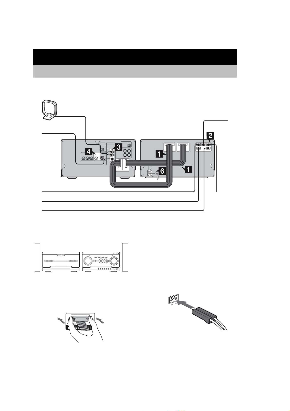
Getting Started
Hooking up the system
Perform the following procedures 1 to 7 to hook up your system using the suppli ed cords and
accessories. European model is used for illustration purpose.
AM loop antenna
FM lead antenna
CD/DVD player/Tuner Amplifier/Tape deck
To front speaker (right)
To surround speaker (right)
To surround speaker (left)
Preparation
Place the components as shown below.
Amplifier/
Tape deck
CD/DVD player/
Tuner
To center
speaker
To front speaker
(left)
Note
The system cable is used to send signals and electricity
between the components for interlinked operation.
Be sure to insert the connector horizontally until it
clicks into place. Otherwise the system will not operate
correctly.
1 Connect the system control cables to
the SYSTEM CONTROL connectors on
the tape deck.
Connect to the same numbered jack in the
order indicated on the rear panel.
2 Connect the speakers.
Be sure to match the appropriate speaker
cords from the speaker terminals to the
corresponding SPEAKER terminals on the
tape deck.
4

SECTION 2
)
DISASSEMBLY
•The equipment can be removed using the following procedure.
SET
CASE
DXA-WZ8D
SWITCHING POWER,
DC FAN
TC MAIN BOARD
FRONT AMP BOARD,
SURROUND AMP BOARD
Note : Follow the disassembly procedure in the numerical order given.
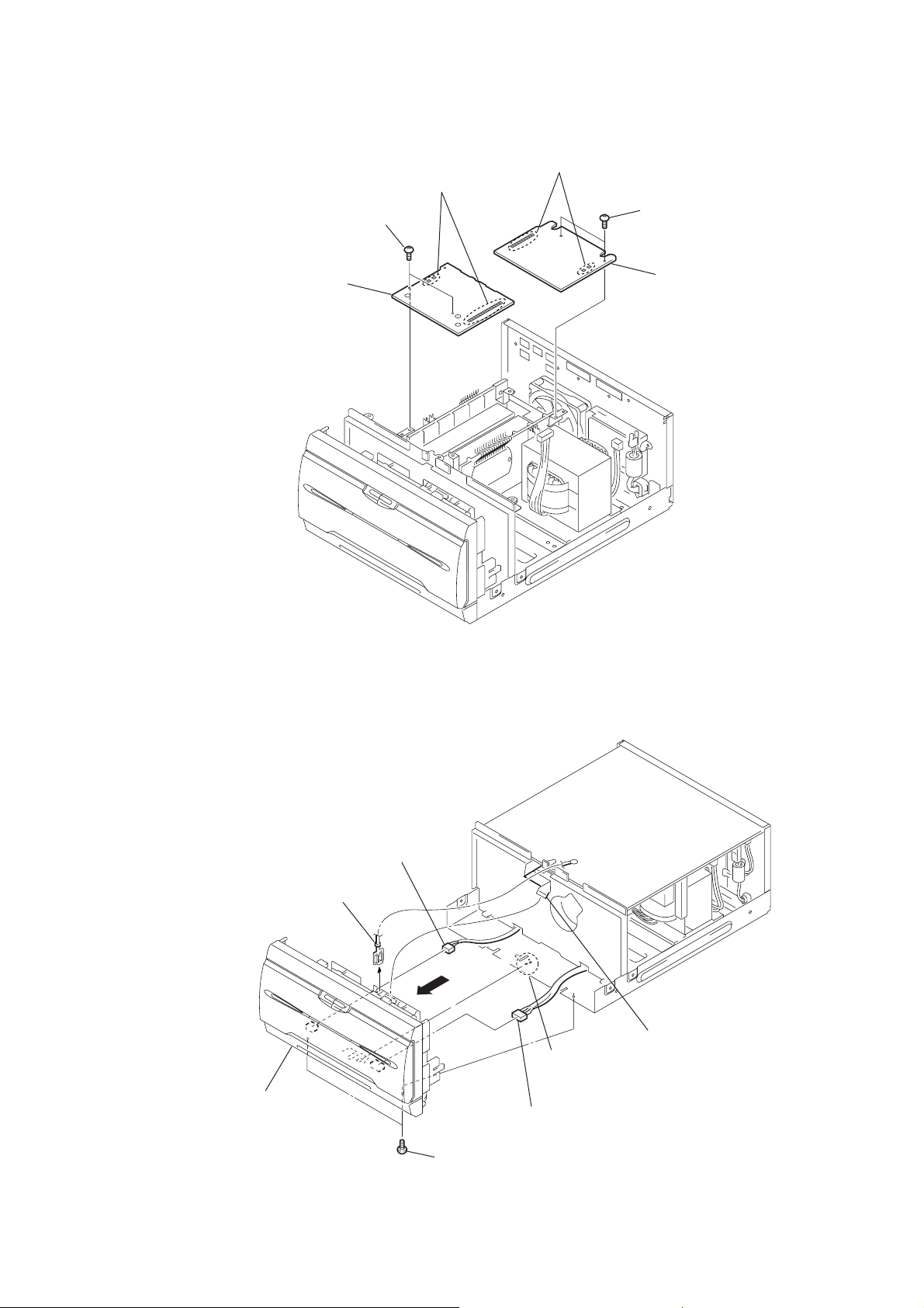
2-1. Case
4
case
2
two screws
(case 3 TP2)
FRONT PANEL ASSY
TAPE MECHANISM DECK
(CWM43RR23)
LID (TC) ASSY,
HOLDER (A) ASSY,
HOLDER (B) ASSY
3
three screws
(+BVTP 3
×
8
1
two screws
(case 3 TP2)
5

DXA-WZ8D
)
2-2. Switching Power, DC Fan and Back Panel
8
connector
(CN204)
q;
back panel
9
DC fan
3
connector
(CN201)
7
two screws
(+BVTP 3
×
8)
2
five screws
(+BVTP 3
6
switching power
4
connector
(CN101)
1
five screws
(+BVTP 3
×
8)
×
8)
2-3. TC MAIN Board
8
connector
(CN502)
9
connector
(CN501)
3
wire (flat type)
(13 core)
4
lead with connector
q;
connector
(CN301)
6
(CN701)
7
connector
(CN401)
connector
5
connector
(CN204)
5
two screws
(+BVTP 3
2
three screws
(+BVTP 3 × 8)
×
8)
qj
MAIN board
qh
connector
(CN201)
qg
connector
(CN101)
1
five screws
(+BVTP 3
×
8
qa
connector
(CN302)
qd
(CN605)
qs
connector
(CN102)
connector
qf
connector
(CN604)
6
2-4. FRONT AMP Board and SURROUND AMP Board
1
Remove the soldering.
2
two screws
3
FRONT
(+BVTP 3
AMP board
×
8)
4
Remove the soldering.
5
two screws
(+BVTP 3 × 8)
6
SURROUND
DXA-WZ8D
AMP board
2-5. Front Panel Assy
3
7
front panel assy
5
lead with connector
connector
4
6
connector
claw
2
wire (flat type)
(13 core)
1
two screws
(+BVTP 3
×
8)
7
DXA-WZ8D
)
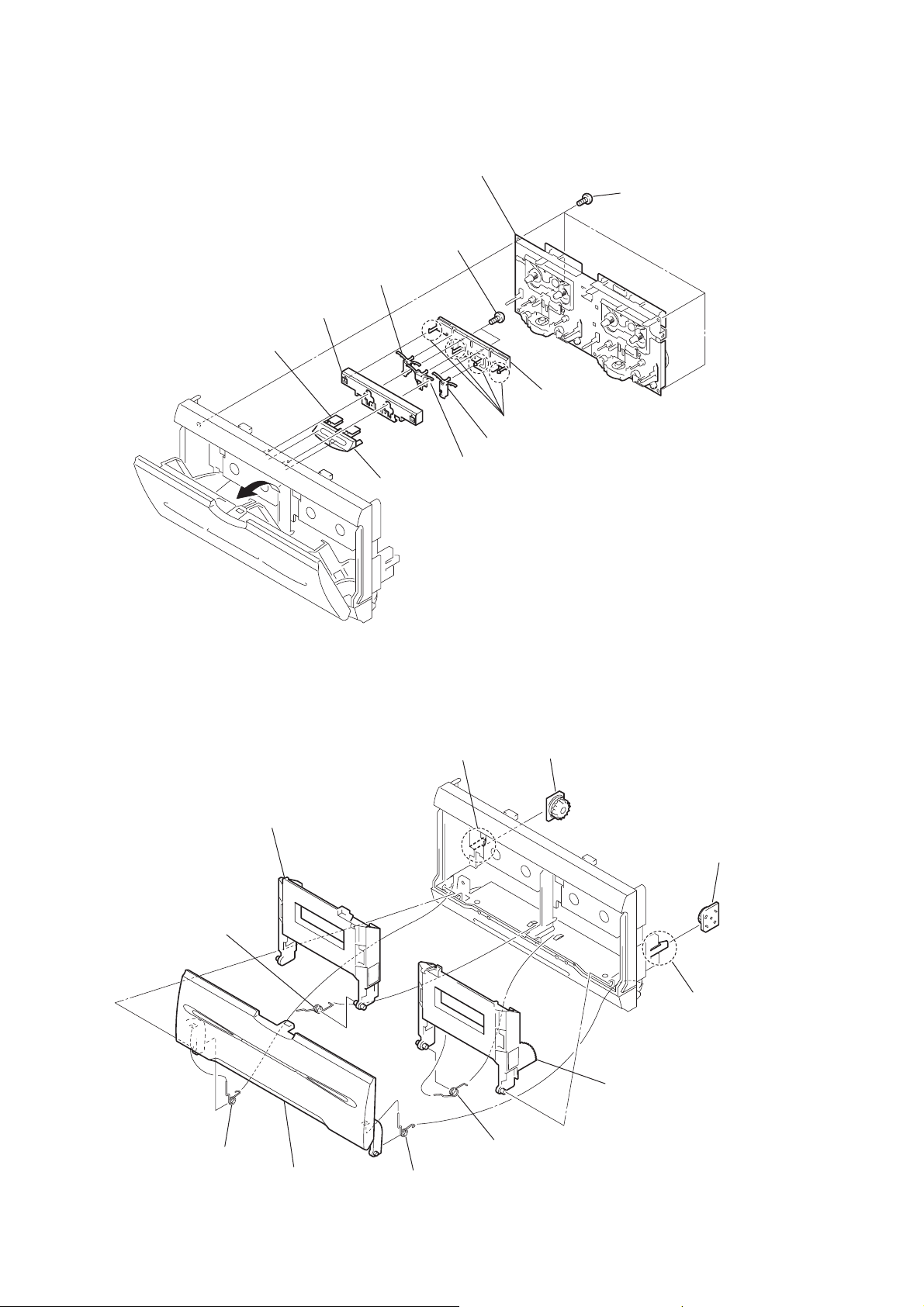
2-6. Tape Mechanism Deck (CWM43RR23)
q;
holder (lock)
qa
button (A)
3
8
lever (L)
4
two screws
(+BVTP 2.6
qs
button (B)
2
tape
mechanism deck (CWM43RR23)
×
8)
5
four claws
7
lever (R)
9
lever (C)
6
base lock
1
four screws
(+BVTP 2.6
×
8
2-7. Lid (TC) Assy, Holder (A) Assy and Holder (B) Assy
7
holder (A) assy
6
spring holder (A)
4
claw
5
damper
qa
holder (B) assy
9
damper
8
claw
q;
1
spring (lid)
3
lid (TC) assy
2
spring (lid-R)
spring holder (B)
8
SECTION 3
)
ELECTRICAL ADJUSTMENTS
DXA-WZ8D
DECK SECTION
Note: Confirm each contents of this section first of all. If the results are
not satisfied, do the adjustment.
0 dB=0.775 V
1. Demagnetize the record/playback head with a head
demagnetizer.
2. Do not use a magnetized screwdriver for the adjustments.
3. After the adjustments, apply suitable locking compound to the
parts adjust.
4. The adjustments should be performed with the rated power
supply voltage unless otherwise noted.
5. The adjustments should be performed in the order given in this
service manual.
6. The adjustments should be performed for both L-CH and RCH.
7. Switches and controls should be set as follows unless otherwise
specified.
•Test Tape
Tape Signal Used for
P-4-A63J 10 kHz, –10 dB Azimuth Adjustment
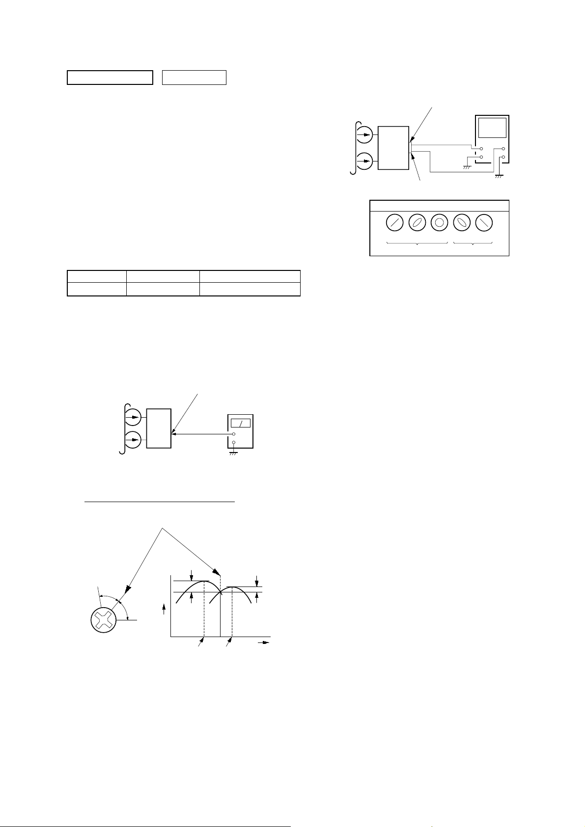
Record/Playback Head Azimuth Adjustment
Procedure:
1. Mode: Playback
3. Mode: Playback
test tape
P-4-A63J
(10 kHz, –10 dB)
L-CH
set
R-CH
in phase 45°90°135°180
SPEAKER terminals (TM401
L-CH
R-CH
waveform of oscilloscope
good
oscilloscope
wrong
H
V
°
4. Repeat step 1 to 3 in playback (REV) mode.
5. After the adjustments, apply suitable locking compound to the
pats adjusted.
test tape
P-4-A63J
(10 kHz, –10 dB)
SPEAKER terminals (TM402)
L-CH, R-CH
level meter
set
+
–
2. Turn the adjustment screw and check output peaks. If the peaks
do not match for L-CH and R-CH, turn the adjustment screw
so that outputs match within 1dB of peak.
Output
level
within
1 dB
L-CH
peak
R-CH
peak
within
1 dB
Screw
position
L-CH
peak
Screw
position
R-CH
peak
9