

Sony DXA-WZ5 Service Manual
DXA-WZ5
Amplifier section
European model:
DIN power output (rated):75 + 75 watts (6 ohms at
1kHz, DIN)
Continuous RMS power output (reference):
100 + 100 watts (6 ohms
at 1 kHz, 10% THD)
atat1kHz, 10% THD)
at 1 kHz, 10% THD)
Music power output (reference):
200 + 200 watts (6 ohms
The following measured at AC 120, 220, 240 V AC,
50/60 Hz (Australian model at 240 V AC, 50/60 Hz)
DIN power output (rated):100 + 100 watts (6 ohms
1kHz, DIN)
Continuous RMS power output (reference):
140 + 140 watts (6 ohms
Inputs
MD (VIDEO) IN (phono jacks):
Voltage 450 mV/250 mV,
impedance 47 kilohms
Outputs
PHONES (stereo mini jack):
Accepts headphones of
8 ohms or more
MD (VIDEO) OUT (phono jacks):
Voltage 250 mV,
impedance 1 kilohms
FRONT SPEAKER: Use only the supplied
speaker SS-WZ5/WZ5E
SUB WOOFER (Except for Europe an model):
Voltage 320mV,
impedance 1 kilohms
Tape deck section
Except for European model:
Recording system 4-track 2-channel, stereo
Frequency response 50 – 13,000 Hz (±3 dB),
using Sony TYPE I
cassettes
General
Power requirements
European model: 230 V AC, 50/60 Hz
Australian model: 230 – 240 V AC, 50/60 Hz
TW model: 120 V AC, 50/60 Hz
Other models: 120 V, 220 V or
230 – 240V AC, 50/60 Hz
Adjustable with voltage
selector
Power consumption
European model: 150 watts
0.3 watts (at the Power
Saving Mode)
Except for European model:
180 watts
Dimensions (w/h/d)
Amplifier/Tape deck:
Amplifier/Tape deck
Approx. 255 × 135 ×
330 mm
Mass
European model: Approx. 6.0 kg
Except for European model:
Approx. 6.3 kg
Design and specifications are subject to change
without notice.
SERVICE MANUAL
Ver 1.0 2003. 04
• DXA-WZ5 is deck and amplifier
section in MHC-WZ5.
Tape deck
Section
SPECIFICATIONS
AEP Model
UK Model
E Model
Australian Model
Model Name Using Similar Mechanism NEW
Tape Transport Mechanism T ype CWM43RR23
9-877-330-01
2003D1600-1
© 2003.04
Sony Corporation
Home Audio Company
Published by Sony Engineering Corporation
STEREO CASSETTE DECK AMPLIFIER
DXA-WZ5
[When bringing in the equipment for service]
In case of repairing, please bring the entire system set([HCD-WZ5,
DXA-WZ5],except for the speaker) to the service station.
Unleaded solder
Boards requiring use of unleaded solder are printed with the leadfree mark (LF) indicating the solder contains no lead.
(Caution: Some printed circuit boards may not come printed with
the lead free mark due to their particular size.)
: LEAD FREE MARK
Unleaded solder has the following characteristics.
• Unleaded solder melts at a temperature about 40°C higher than
ordinary solder.
Ordinary soldering irons can be used but the iron tip has to be
applied to the solder joint for a slightly longer time.
Soldering irons using a temperature regulator should be set to
about 350°C.
Caution: The printed pattern (copper foil) may peel away if the
heated tip is applied for too long, so be careful!
• Strong viscosity
Unleaded solder is more viscous (sticky, less prone to flow) than
ordinary solder so use caution not to let solder bridges occur such
as on IC pins, etc.
• Usable with ordinary solder
It is best to use only unleaded solder but unleaded solder may
also be added to ordinary solder.
Notes on chip component replacement
•Never reuse a disconnected chip component.
• Notice that the minus side of a tantalum capacitor may be
damaged by heat.
TABLE OF CONTENTS
1. GENERAL ·········································································· 3
2. DISASSEMBLY ························································· 5
2-1. Case ··············································································· 5
2-2. Switching Power, DC Fan, Back Panel ························· 6
2-3. MAIN Board ································································· 6
2-4. AMP Board ··································································· 7
2-5. Front Panel Assy····························································7
2-6. Tape mechanism deck (CWM43RR23) ························ 8
2-7. Lid (TC) Assy, Holder (A) Assy, Holder (B) Assy········8
3. ELECTRICAL ADJUSTMENTS ································· 9
4. DIAGRAMS······································································ 10
4-1. Block Diagrams - Main Section - ································ 11
4-2. Printed Wiring Board - MAIN Board - ······················· 12
4-3. Schematic Diagram - MAIN Board (1/2) - ················· 13
- MAIN Board (2/2) - ················· 14
4-4. Printed Wiring Board - AMP Board -·························· 15
4-5. Schematic Diagram - AMP Board - ···························· 16
5. EXPLODED VIEWS
5-1. Front Panel Section ····················································· 17
5-2. Chassis Section ···························································· 18
5-3. Tape Mechanism Deck Section ··································· 19
6. ELECTRICAL PARTS LIST······································· 20
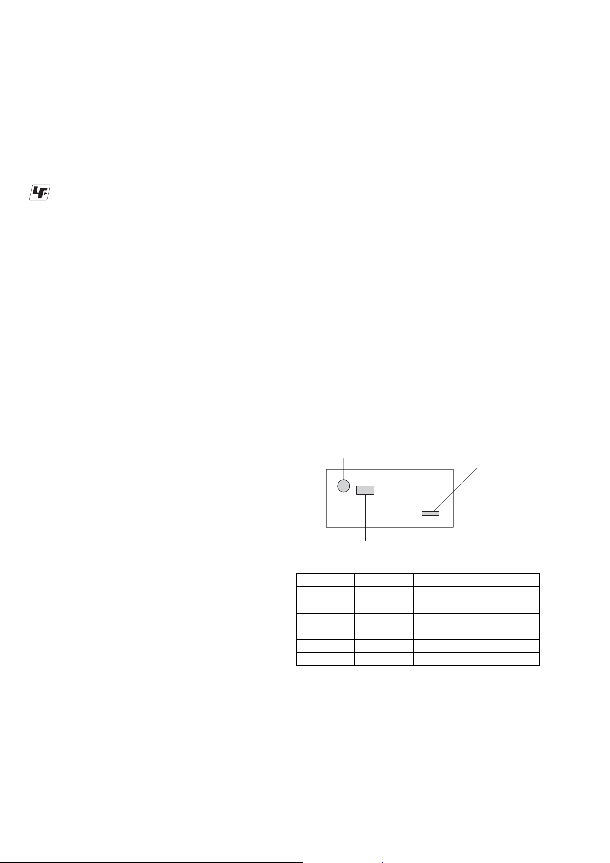
MODEL IDENTIFICATION
— BACK PANEL —
Flexible Circuit Board Repairing
•Keep the temperature of soldering iron around 270˚C
during repairing.
• Do not touch the soldering iron on the same conductor of the
circuit board (within 3 times).
• Be careful not to apply force on the conductor when soldering
or unsoldering.
SAFETY-RELATED COMPONENT WARNING!!
VOLTAGE SELECTOR Switch
Power Voltage Indication
MODEL
AEP, UK models
E2 model
E3 model
AUS model
KR model
TW model
•Abbreviation
AUS: Australian model
E2 : 120V AC Area in E model
E3 : 240V AC Area in E model
KR : Korean model
TW : Taiwan model
PARTS No.
4-244-468-0s
4-244-468-1s
4-244-468-1s
4-244-468-3s
4-244-468-9s
4-244-468-8s
PARTS No.
POWER V OL TA GE INDICA TION
AC: 230V 50/60HZ
AC: 120V 60HZ
AC: 240V 50HZ
AC: 230-240V 50/60HZ
AC: 220V 50/60HZ
AC: 120V 50/60HZ
COMPONENTS IDENTIFIED BY MARK 0 OR DOTTED LINE WITH
MARK 0 ON THE SCHEMATIC DIAGRAMS AND IN THE PARTS
LIST ARE CRITICAL TO SAFE OPERATION. REPLACE THESE
COMPONENTS WITH SONY PARTS WHOSE PART NUMBERS
APPEAR AS SHOWN IN THIS MANUAL OR IN SUPPLEMENTS
PUBLISHED BY SONY.
2
Main unit
SECTION 1
GENERAL
DXA-WZ5
This section is extracted
from instruction manual.
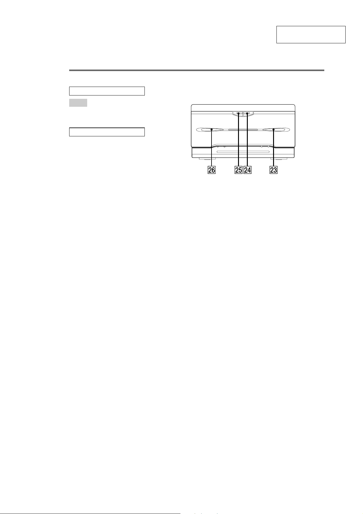
ALPHABETICAL ORDER
A – L
Deck A wh
Deck B wd
BUTTON DESCRIPTIONS
A Z (eject) wg (15)
Z B (eject ) wf (15)
Amplifier Tape deck
3
DXA-WZ5
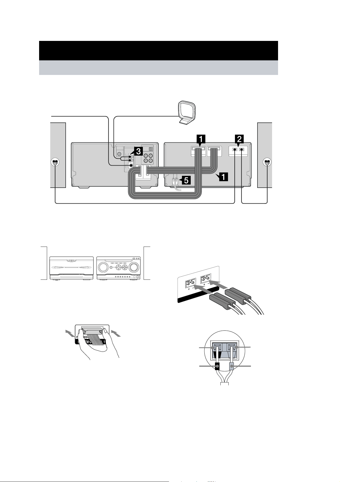
Getting Started
Hooking up the system
Perform the following procedures 1 to 5 to hook up your system using the supplied cords and
accessories. Australian model is used for illustration purpose.
FM lead antenna
CD player/
Tuner Tape deck
Front
speaker (right)
Preparation
Place the components as shown below.
Amplifier/
Tape deck
CD player/
Tuner
AM loop antenna
Amplifier/
Front
speaker (left)
2 Connect the speakers.
Connect the speaker co rds to the
SPEAKER terminals on the tape deck and
to the ter minals on the spea k ers as shown
below.
L
R
1 Connect the system control cables to
the SYSTEM CONTROL connectors on
the tape deck.
Connect to the same numbered jack in the
order indicat ed on the rear panel.
Note
The system cable is used to sen d signals and el ectricity
between the components f or inter li nke d ope r at ion.
Be sure to insert the connector horizontally until it
clicks into plac e. Otherwise the syst em will not operat e
correctly.
SPEAKER
Speakers
Black (#)
Black (#)
Gray (3)
Gray (3)
4
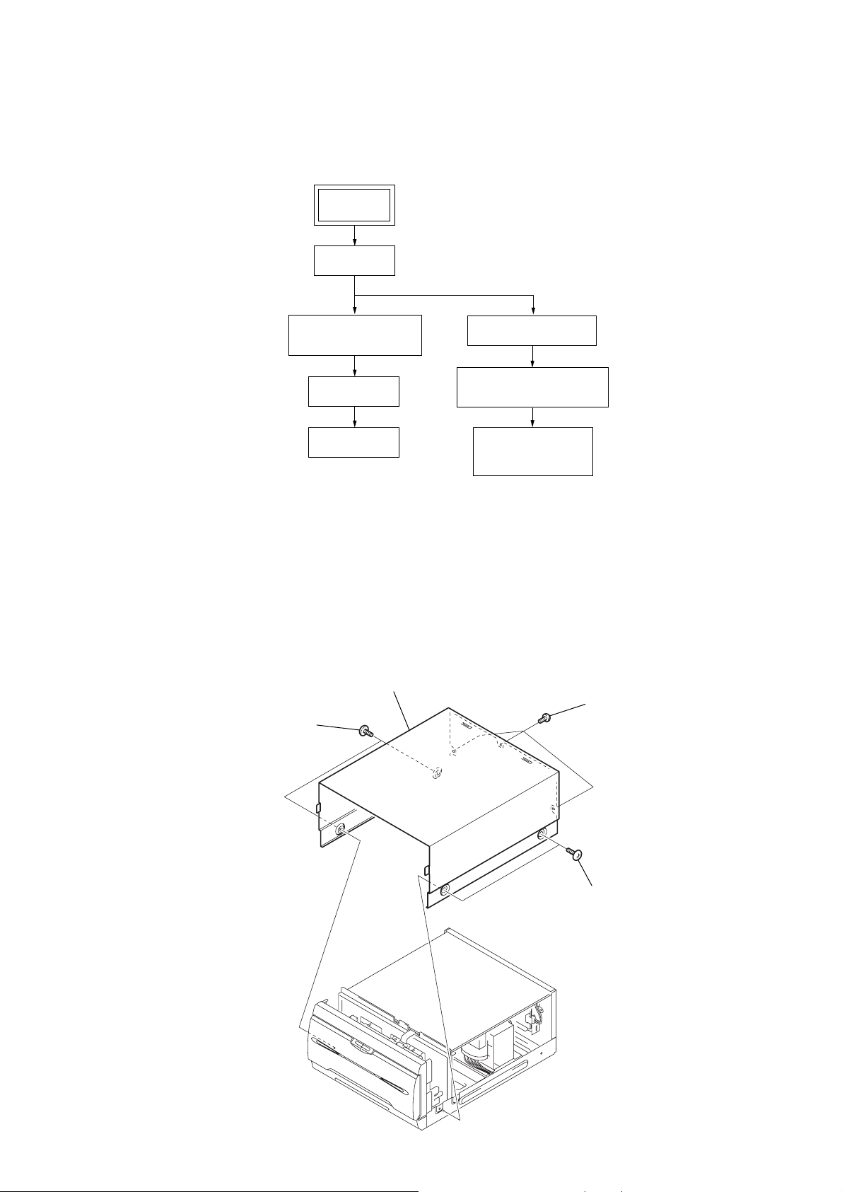
SECTION 2
)
DISASSEMBLY
•The equipment can be removed using the following procedure.
SET
CASE
DXA-WZ5
SWITCHING POWER,
DC FAN, BACK PANEL
MAIN BOARD
AMP BOARD
Note : Follow the disassembly procedure in the numerical order given.
2-1. Case
4
case
2
two screws
(case 3 TP2)
FRONT PANEL ASSY
TAPE MECHANISM DECK
(CWM43RR23)
LID (TC) ASSY,
HOLDER (A) ASSY,
HOLDER (B) ASSY
3
three screws
(+BVTP 3
×
8
1
two screws
(case 3 TP2)
5
DXA-WZ5
r
d
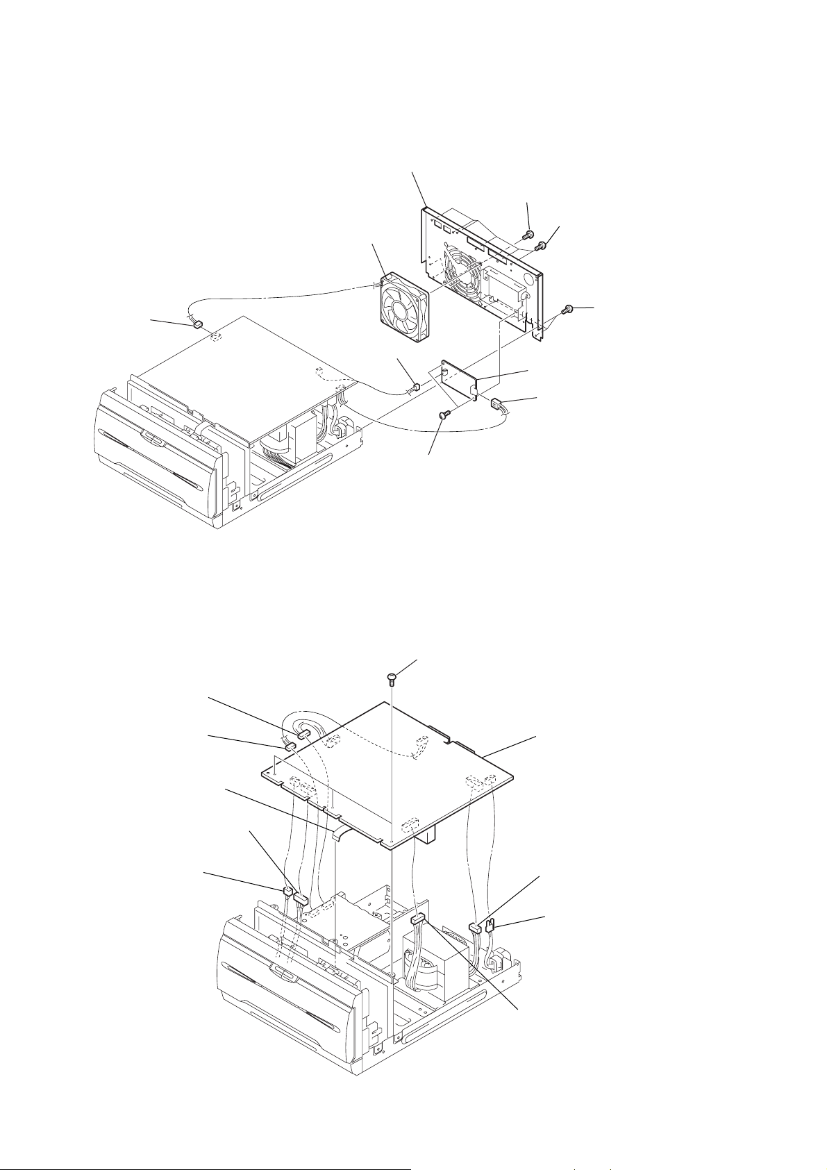
2-2. Switching Power, DC Fan, Back Panel
8
connector
(CN204)
q;
back panel
9
DC fan
3
connector
(CN201)
7
two screws
(+BVTP 3
×
8)
2
six screws
(+BVTP 3
6
switching power
4
connector
(CN101)
1
five screws
(+BVTP 3
×
8)
×
8)
2-3. MAIN Board
2
connector
(CN502)
3
connector
(CN501)
4
wire (flat type)
(13 core)
5
connector
(CN302)
5
two screws
(+BVTP 3
1
×
8)
three screws
(+BVTP 3
×
8)
q;
MAIN boar
6
connector
(CN301)
8
connector
(CN605)
9
(CN604)
7
connector
(CN102)
connecto
6
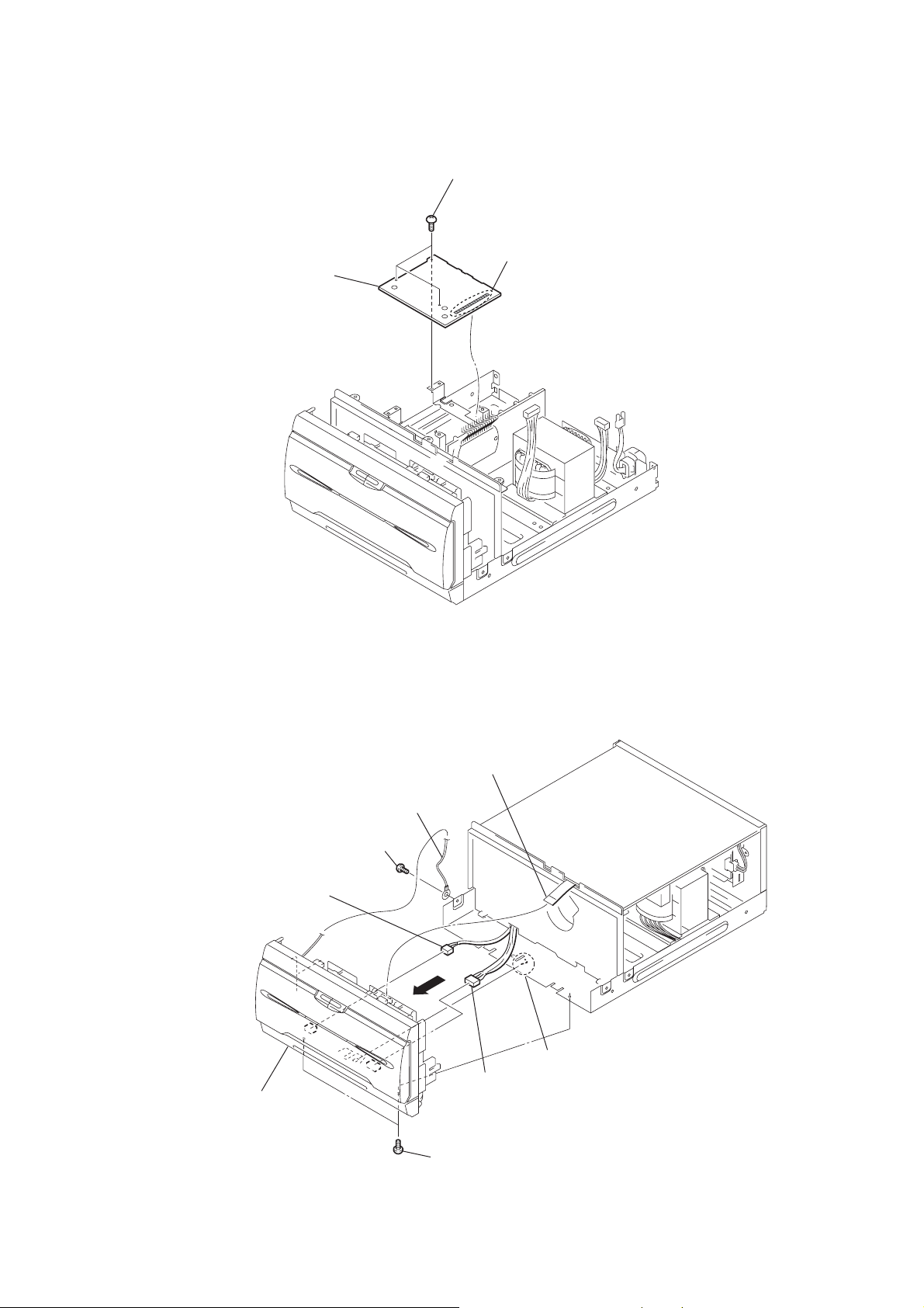
2-4. AMP Board
3
AMP board
2
three screws
(+BVTP 3
×
8)
1
Remove the soldering.
DXA-WZ5
2-5. Front Panel Assy
8
front panel
assy
3
(+BVTP 3
6
connector
screw
2
wire (flat type)
(13 core)
4
wire
×
8)
5
claw
7
connector
1
two screws
(+BVTP 3
×
8)
7
DXA-WZ5
)
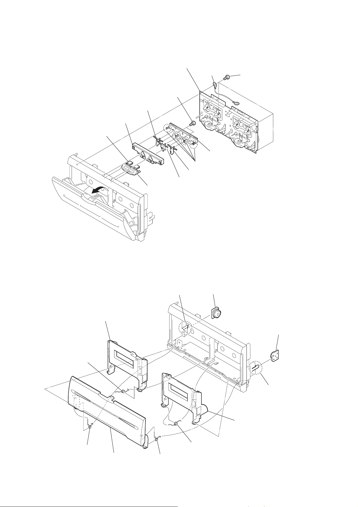
2-6. Tape mechanism deck (CWM43RR23)
qa
holder (lock)
qs
button (A)
4
9
lever (L)
5
two screws
(+BVTP 2.6
qd
button (B)
3
tape
mechanism deck (CWM43RR23)
2
wire
×
8)
6
four claws
8
lever (R)
q;
lever (C)
7
base lock
1
four screws
(+BVTP 2.6
×
8
2-7. Lid (TC) Assy, Holder (A) Assy, Holder (B) Assy
7
holder (A) assy
6
spring holder (A)
4
claw
5
damper
qa
holder (B) assy
9
damper
8
claw
q;
1
spring (lid)
3
lid (TC) assy
2
spring (lid-R)
spring holder (B)
8
 Loading...