

SONY HCD BX7, DX7J HCD BX7, DX7J Service Manual
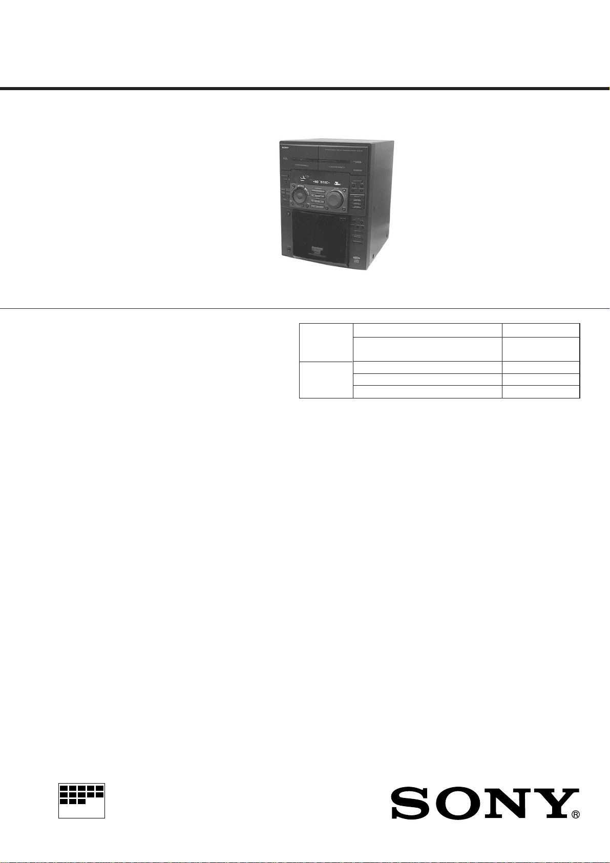
HCD-F50/F100/FR1
SERVICE MANUAL
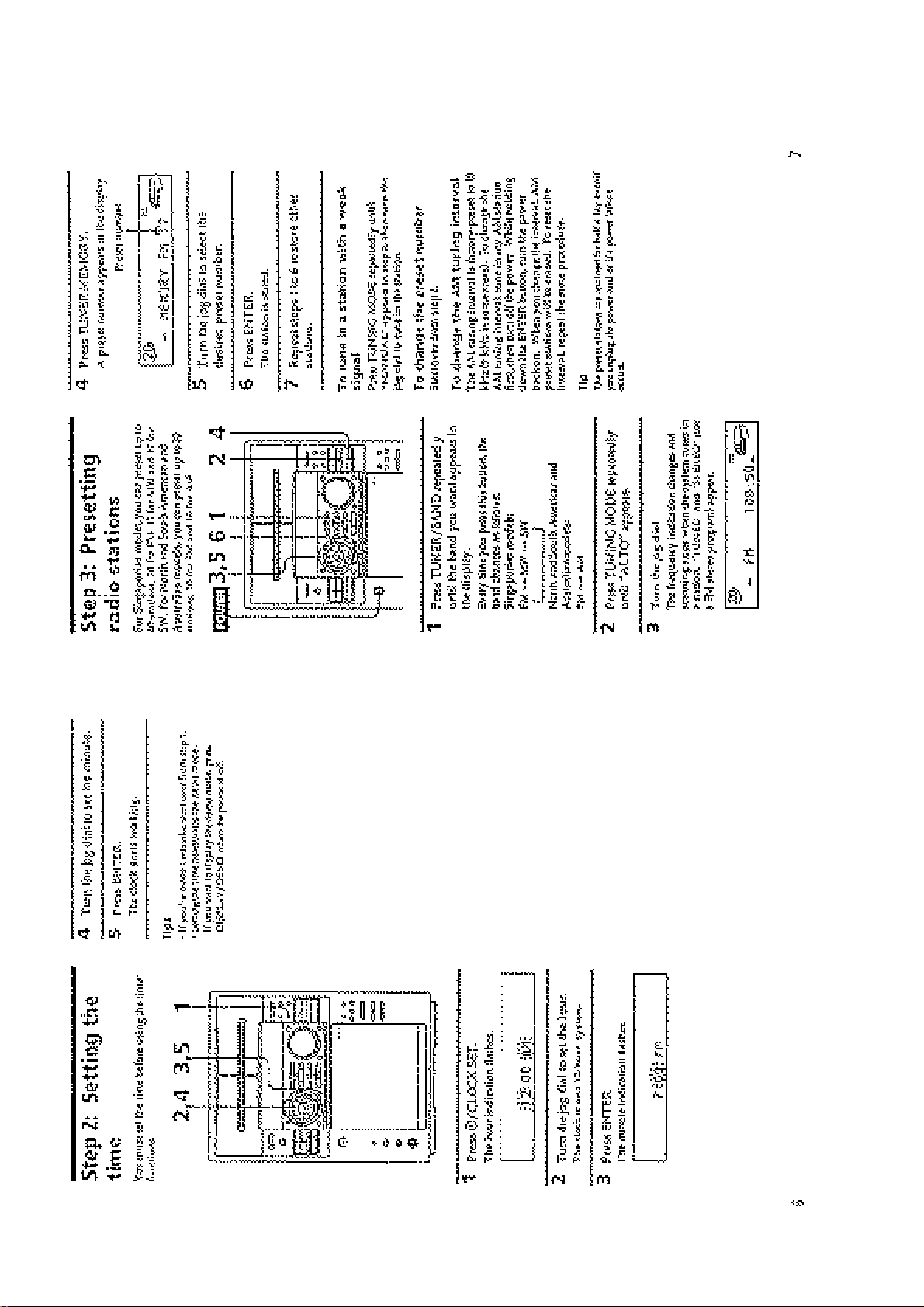
HCD-F50/F100/FR1 is the tuner, deck,
CD and amplifier section in MHC-F50/
F100/FR1.
Photo: HCD-FR1
US Model
Canadian Model
HCD-F50/F100
AEP Model
UK Model
E Model
Australian Model
HCD-FR1
* Dolby noise reduction manufacrured
under license from Dolby Laboratories
Licensing corporation.
"DOLBY" and the double-D symbol a
are trademarks of Dolby Laboratories
Licensing Corporation.
For the US model
AUDIO POWER SPECIFICATIONS
POWER OUTPUT AND TOTAL
HARMONIC DISTORTION:
With 8 ohm loads, both channels driven, from
70-20,000 Hz; rated 100 watts per channel
minimum RMS power, with no more than
0.9% total harmonic distortion from 250
milliwatts to rated output.
Amplifier section
Continuous RMS power output
Canadian model
100+100 watts
(8 ohms at 1 kHz, 5% THD)
(F100)
60+60 watts
(6 ohms at 1 kHz, 5% THD)
(F50)
Other models 100+100 watts
(8 ohm at 1 kHz, 10% THD)
Peak music power output (EXCEPT US, Canadian) :
1400 watts
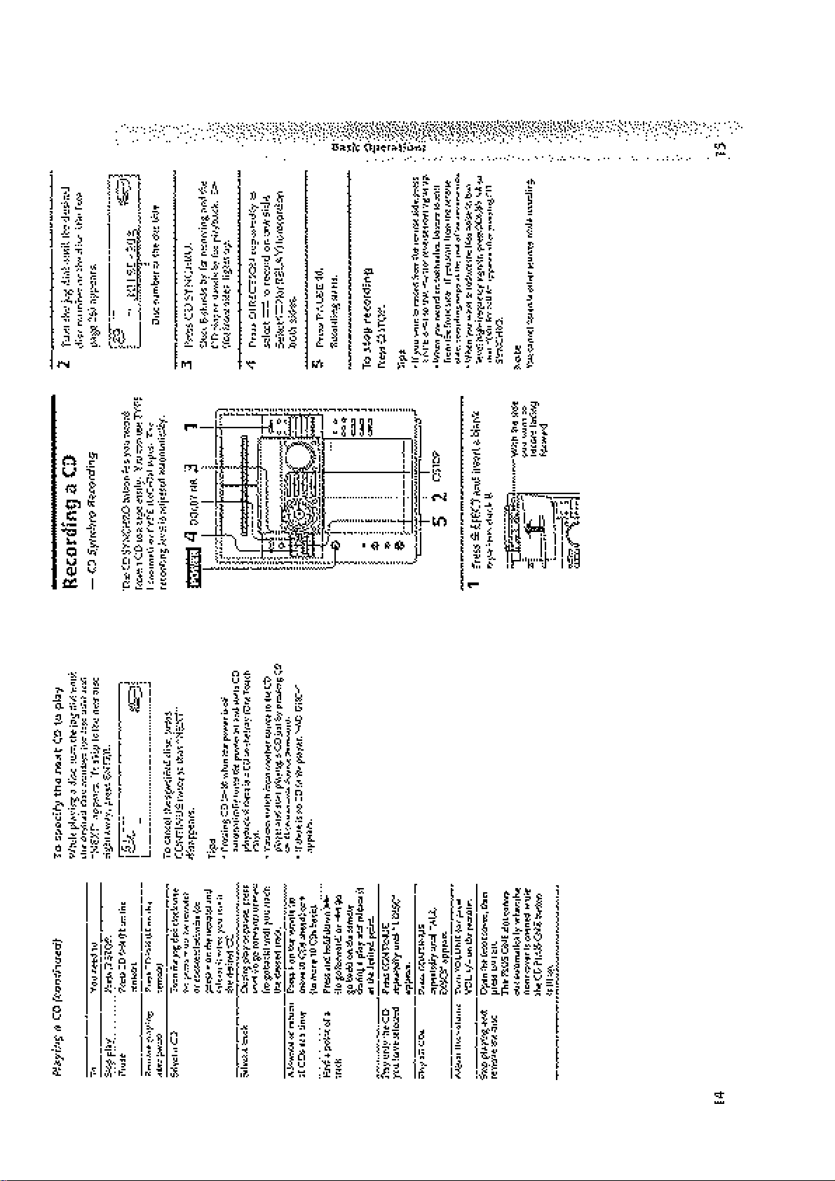
CD
Section
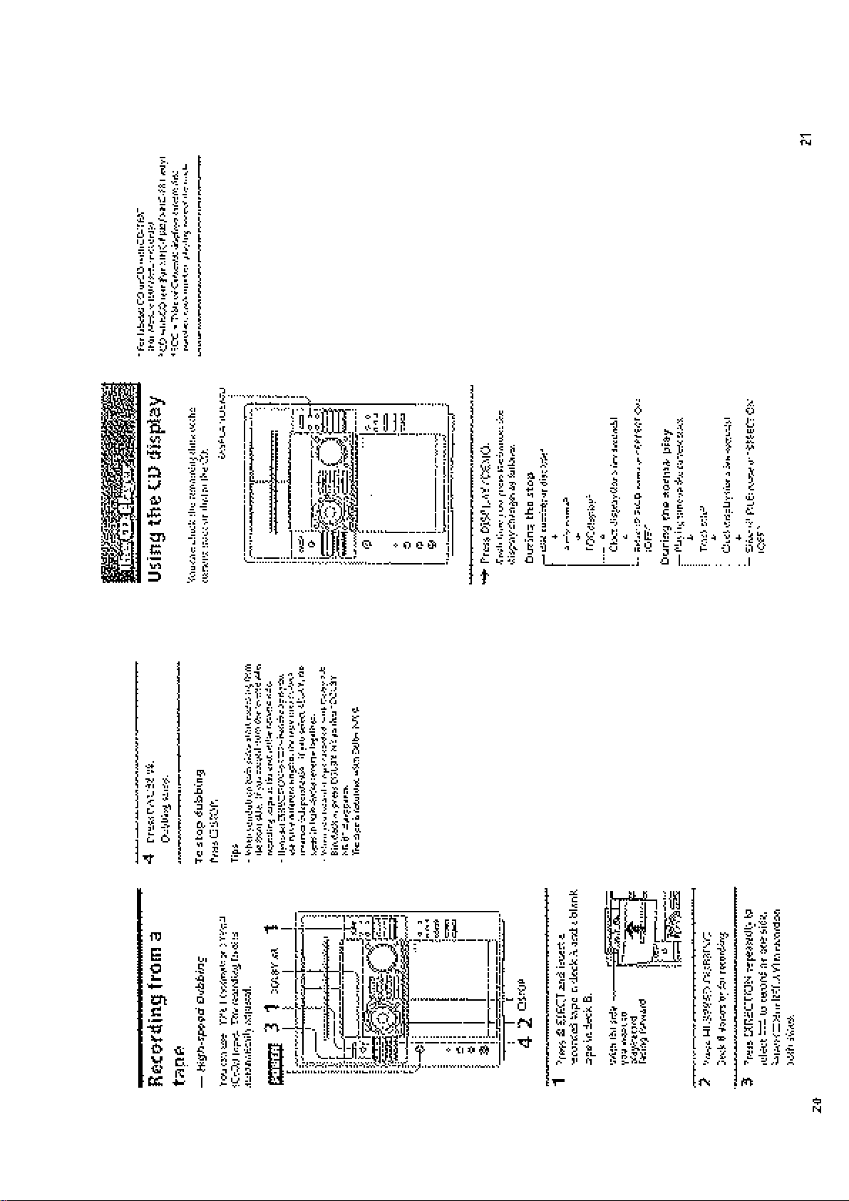
Tape deck
Section
Model Name Using Similar Mechanism NEW
CD Mechanism Type
Optical Pick-up Name
Model Name Using
Tape Transport Mechanism Type TCM-220WR2
SPECIFICATIONS
Inputs VIDEO/MD IN (phono jacks) :
Outputs VIDEO/MD OUT (phono jacks)
voltage 250 mV,impedance 47
kilohms
MIX MIC (phone jack)
(Singapore model):
sensitivity 1 mV,
impedance 10 kilohms
: voltage 250 mV impedance
1 kilohms
PHONES (stereo phone jack) :
accepts headphones of 8 ohms or
more.
SPEAKER : accepts impedance of
8 to 16 ohms (F100/FR1)
accepts impedance of 6 to 16 ohms
(F50)
SURROUND SPEAKER
(F100/FR1):
accepts impedance of 16 ohms.
SUPER WOOFER (F100/FR1):
V oltage 1 V, impedance 1 kilo ohm
CDM-46B1 (F100/FR1)
CDM-46B2 (F50)
KSS-213B/S-N
Similar Mechanism HCD-D690/XB6
CD player section
System Compact disc and digital audio
system
Laser Semiconductor laser
(λ=780nm)
Emission duration: continuous
Laser output Max. 44.6 µW*
*This output is the value measured at a distance of 200 mm
from the objective lens surface
-on the Optical Pick-up Block
with 7 mm aperture.
Wavelength 780-790 nm
CD OPTICAL DIGITAL OUT
(Square optical connector jack, rear panel)
Wavelength 600 nm
– Continued on next page –
MICROFILM
MINI HI-FI COMPONENT SYSTEM
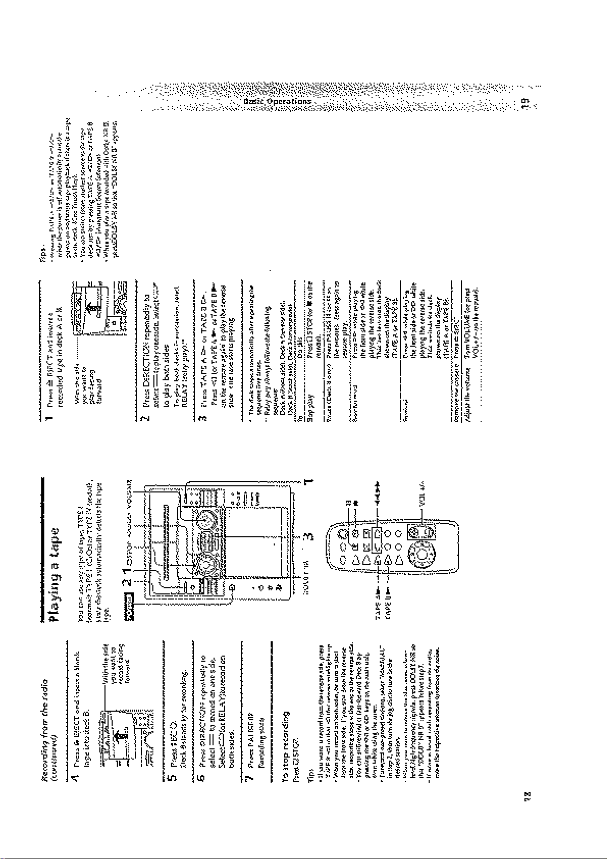
Tape player section
Recording system 4-track 2-channel stereo
Frequency response 60 - 13,000 Hz (±3 dB), using Sony TYPE I cassette
(DOLBY NR OFF) 60 - 14,000 Hz (±3 dB), using Sony TYPE II cassette
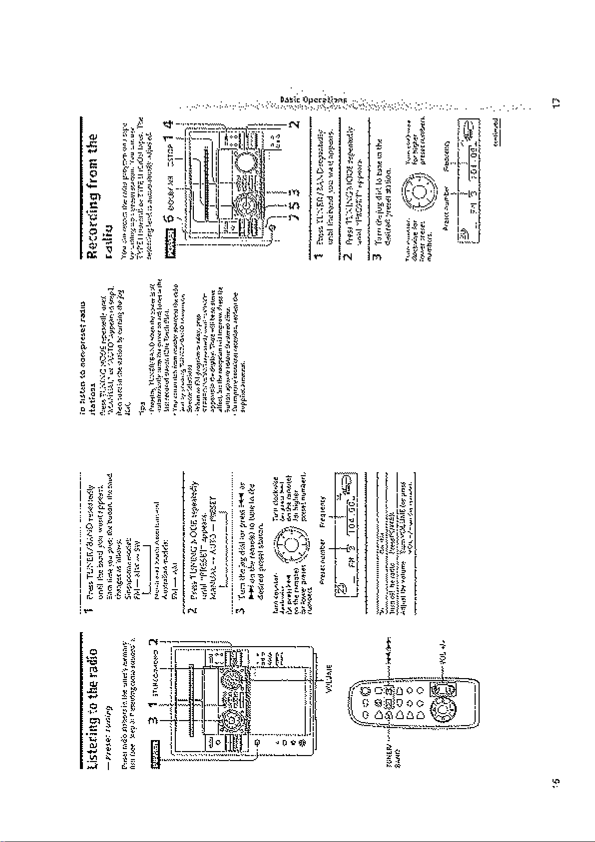
Tuner section
FM stereo, FM/AM superheterodyne tuner
FM tuner section
Tuning range 87.5 - 108,0 MHz
Antenna terminals 75 ohm unbalanced
Intermediate frequency 10.7 MHz
AM tuner section
Tuning range
North American model:
530 - 1,710 kHz
(with the AM tuning interval set at 10kHz)
531 - 1,710 kHz
(with the AM tuning interval set at 9 kHz)
Singaporian model: MW 531 - 1,602 kHz
(with the MW tuning interval set at 9 kHz)
530 - 1,710 kHz
(with the MW tuning interval set at 10 kHz)
SW 5.95 - 17.90 MHz
(with the SW tuning interval set at 5 kHz)
Other models:
531 - 1,602 kHz
(with the AM tuning interval set at 9 kHz)
530 - 1,710 kHz
(with the AM tuning interval set at 10 kHz)
Intermediate frequency 450 kHz
Antenna AM loop antenna
External antenna terminal
General
Power requirements
North American model: 120 V AC, 60 Hz
Australian model: 220 - 240 V AC, 50/60 Hz
AEP, UK, G models: 220 - 230V AC, 50/60 Hz
Other models: 110 - 120 V or 220 - 240 V AC,
50/60 Hz Adjustable with voltage selector
Power consumption
U.S. model: 195 watts (HCD-F100)
110 watts (HCD-F50)
Canadian model: 195 watts (HCD-F100)
120 watts (HCD-F50)
Other models: 210 watts
Dimensions (w/h/d) Approx. 280×375×450 mm
Mass Approx. 11.5 kg (HCD-F100/FR1)
Approx. 10 kg (HCD-F50)
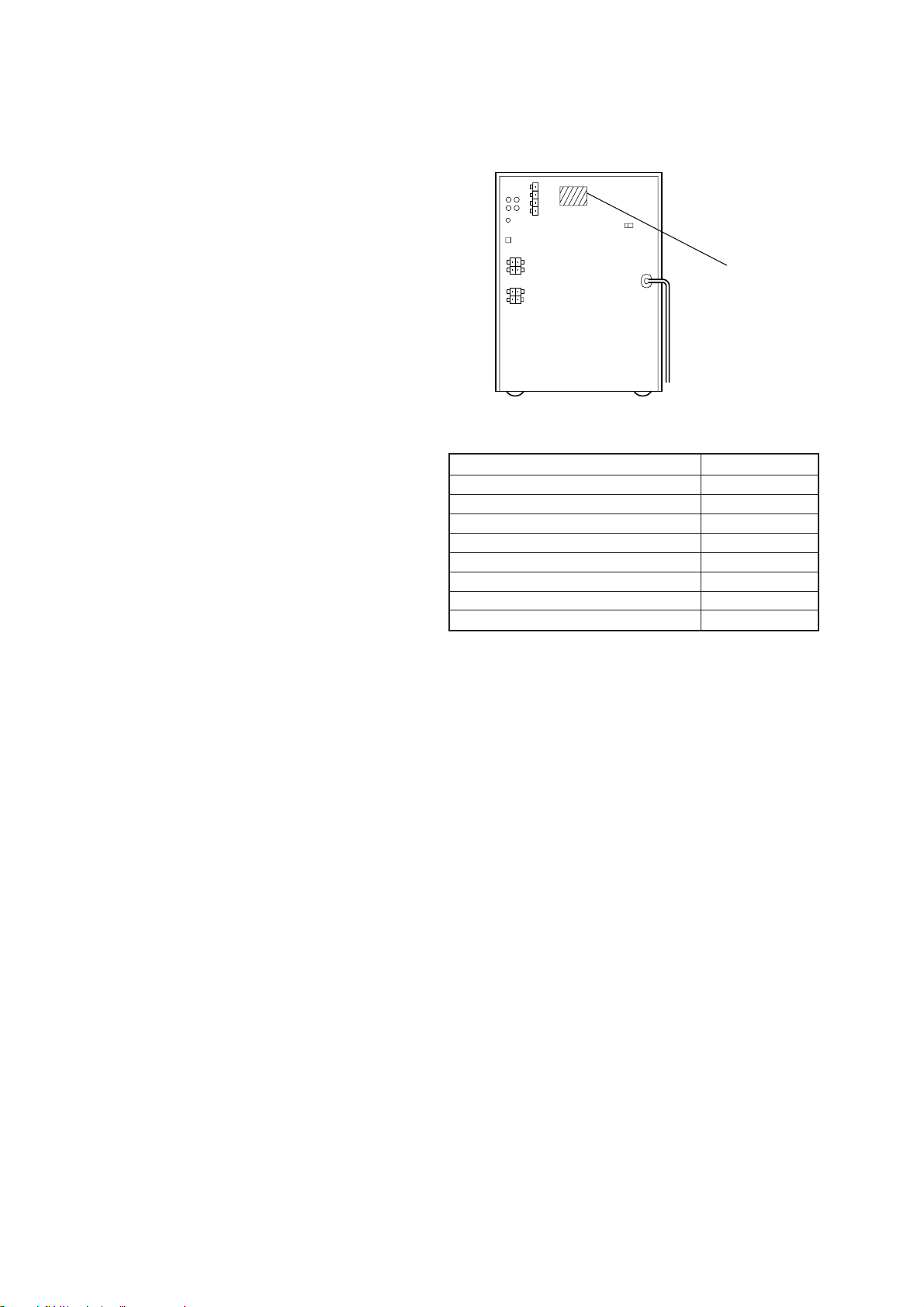
MEDEL IDENTIFICATION
– BACK PANEL –
PARTS No.
MODEL PARTS NO.
F50 : US model 4-990-400-0π
F50 : Canadeian model 4-990-400-1π
F100 : US model 4-990-364-0π
F100 : Canadian model 4-990-364-1π
FR1 : AEP, UK, German model 4-990-364-2π
FR1 : E model 4-990-364-5π
FR1 : Australian model 4-990-364-6π
FR1 : Singapore model 4-990-364-9π
Supplied accessories: AM loop antena (1)
Remote RM-SF100 (1) (F100/FR1)
Remote RM-SF50 (1) (F50)
Sony SUM-3 (N5)
batteries (2)
FM lead antenna (1)
Speaker coreds (2)
Design and specifications are subject to change without notice.
– 2 –
CAUTION
Use of controls or adjustments or performance of
procedures other than those specified herein may
result in hazardous radiation exposure.
This appliance is classified as a CLASS 1 LASER product.
The CLASS 1 LASER PRODUCT MARKING is located on
the rear exterior.
Laser component in this product is capable of emitting radiation
exceeding the limit for Class 1.
The following caution label is located inside the unit.
SAFETY CHECK-OUT
After correcting the original service problem, perform the following safety check before releasing the set to the customer:
Check the antenna terminals, metal trim, “metallized” knobs,
screws, and all other exposed metal parts for AC leakage.
Check leakage as described below.
LEAKAGE TEST
The AC leakage from any exposed metal part to earth ground and
from all exposed metal parts to any exposed metal part having a
return to chassis, must not exceed 0.5 mA (500 microampers.).
Leakage current can be measured by any one of three methods.
1. A commercial leakage tester, such as the Simpson 229 or RCA
WT -540A. Follow the manuf acturers’ instructions to use these
instruments.
2. A battery-operated AC milliammeter . The Data Precision 245
digital multimeter is suitable for this job.
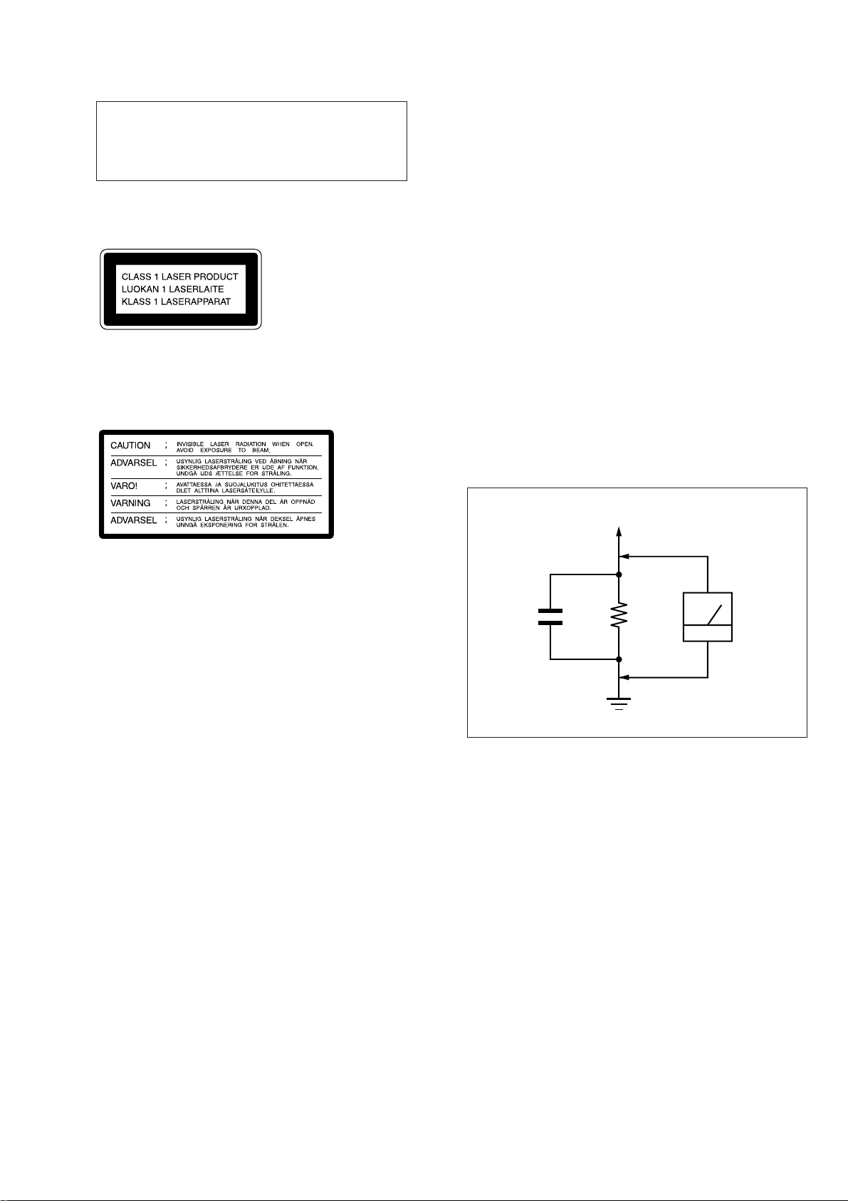
3. Measuring the voltage drop across a resistor by means of a
VOM or battery-operated AC voltmeter. The “limit” indication is 0.75 V, so analog meters must have an accurate lowvoltage scale. The Simpson 250 and Sanwa SH-63Tr d are examples of a passive VOM that is suitable. Nearly all battery
operated digital multimeters that have a 2 V A C range are suitable. (See Fig. A)
To Exposed Metal
Parts on Set
SAFETY-RELATED COMPONENT WARNING!!
COMPONENTS IDENTIFIED BY MARK ! OR DOTTED
LINE WITH MARK ! ON THE SCHEMATIC DIA GRAMS
AND IN THE PARTS LIST ARE CRITICAL TO SAFE
OPERATION. REPLACE THESE COMPONENTS WITH
SONY PARTS WHOSE PART NUMBERS APPEAR AS
SHOWN IN THIS MANUAL OR IN SUPPLEMENTS PUBLISHED BY SONY.
AC
0.15 µF
1.5 k
Ω
Earth Ground
voltmeter
(0.75 V)
Fig. A. Using an AC voltmeter to check AC leakage.
ATTENTION AU COMPOSANT AYANT RAPPORT
À LA SÉCURITÉ!
LES COMPOSANTS IDENTIFIÉS P AR UNE MARQUE !
SUR LES DIAGRAMMES SCHÉMATIQUES ET LA LISTE
DES PIÈCES SONT CRITIQUES POUR LA SÉCURITÉ
DE FONCTIONNEMENT. NE REMPLACER CES COMPOSANTS QUE PAR DES PIÈCES SONY DONT LES
NUMÉROS SONT DONNÉS DANS CE MANUEL OU
DANS LES SUPPLÉMENTS PUBLIÉS PAR SONY.
– 3 –

TABLE OF CONTENTS
Servicing Notes ...........................................................................4
1. GENERAL ....................................................................5
2. DISASSEMBLY ......................................................... 25
3. TEST MODE ..............................................................33
4. MECHANICAL ADJUSTMENTS ........................36
5. ELECTRICAL ADJUSTMENTS
Deck Section.................................................................... 39
Tuner Section...................................................................41
CD Section.......................................................................42
6. DIAGRAMS ................................................................44
6-1. Printed Wiring Board –Tuner Section– ........................... 45
6-2. Schematic Diagram –Tuner Section– ..............................46
6-3. Schematic Diagram –CD Section– ..................................48
6-4. Printed Wiring Board –CD Section– ...............................51
6-5. Printed Wiring Boards –CD Motor Section–...................54
6-6. Schematic Diagram –CD Motor Section– .......................55
6-7. Printed Wiring Boards –Deck Section–........................... 57
6-8. Schematic Diagram –Deck Section– ...............................59
6-9. Schematic Diagram –Main /Power Section–................... 64
6-10. Printed Wiring Boards –Main /Power Section– .............. 69
6-11. Schematic Diagram –Main (3/3) Section– ...................... 73
6-12. Printed Wiring Boards –Panel Section– ..........................75
6-13. Schematic Diagram –Panel Section–............................... 77
6-14. IC Pin Function Description ............................................85
7. EXPLODED- VIEWS ...............................................95
8. ELECTRICAL PARTS LIST ..............................104
SERVICING NOTES
NOTES ON HANDLING THE OPTICAL PICK-UP
BLOCK OR BASE UNIT
The laser diode in the optical pick-up block may suffer electrostatic break-down because of the potential difference generated
by the charged electrostatic load, etc. on clothing and the human
body.
During repair, pay attention to electrostatic break-down and also
use the procedure in the printed matter which is included in the
repair parts.
The flexible board is easily damaged and should be handled with
care.
NOTES ON LASER DIODE EMISSION CHECK
The laser beam on this model is concentrated so as to be focused
on the disc reflective surface by the objective lens in the optical
pick-up block. Therefore, when checking the laser diode emission,
observe from more than 30 cm away from the objective lens.
LASER DIODE AND FOCUS SEARCH OPERATION
CHECK
Carry out the “S curve check” in “CD section adjustment” and
check that the S curve waveform is output repeatedly.
Notes on chip component replacement
• Never reuse a disconnected chip component.
• Notice that the minus side of a tantalum capacitor may be dam-
aged by heat.
Flexible Circuit Board Repairing
• Keep the temperature of the soldering iron around 270 ˚C dur-
ing repairing.
• Do not touch the soldering iron on the same conductor of the
circuit board (within 3 times).
• Be careful not to apply force on the conductor when soldering
or unsoldering.
– 4 –
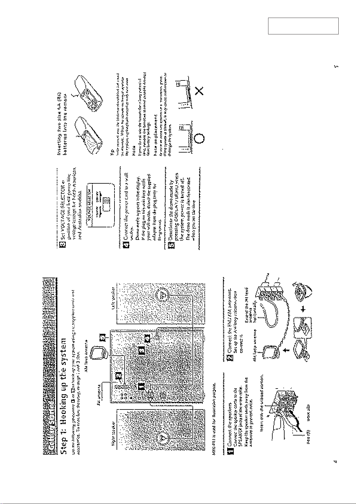
SECTION 1
GENERAL
This section is extracted
from instruction manual.
– 5 –
– 6 –
– 7 –
– 8 –
– 9 –
– 10 –
– 11 –
– 12 –
– 13 –
– 14 –
– 15 –
– 16 –
– 17 –
– 18 –
– 19 –
– 20 –

– 21 –
– 22 –
– 23 –
– 24 –
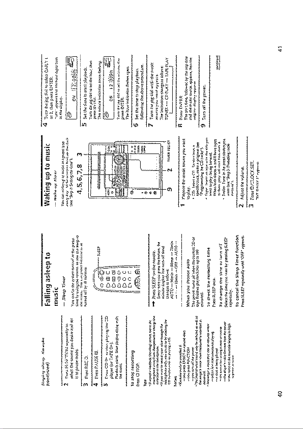
• This set can be disassembled in the order shown below.
SECTION 2
DISASSEMBLY
CASE
(Page 25)
FRONT PANEL
SECTION
(Page 26)
BACK PANEL
(Page 27)
SUB
CHASSIS
(Page 28)
TAPE MECHANISM
DECK SECTION
(Page 31)
DOOR ASS’Y
(Page 26)
MAIN BOARD
(Page 27)
CD MECHANISM
DECK SECTION
(Page 29)
• Abbreviation
G : German
SP : Singapore
AUS : Australian
Note: Follow the disassembly procedure in the numerical order given.
CASE
3
case
POWER TRANSFORMER (T901)
(Page 28)
AUDIO BOARD
(Page 31)
BASE
UNIT
(Page 29)
BD BOARD,
SLED MOTOR
(M102)
(Page 30)
CAPSTAN MOTOR (M1)
(Page 32)
2
three screws
(BVTP 3
OPTICAL
PICK-UP
(KSS-213B/S-N)
(Page 30)
×
8)
1
three screws
(CASE3 TP2)
1
three screws
(CASE3 TP2)
– 25 –
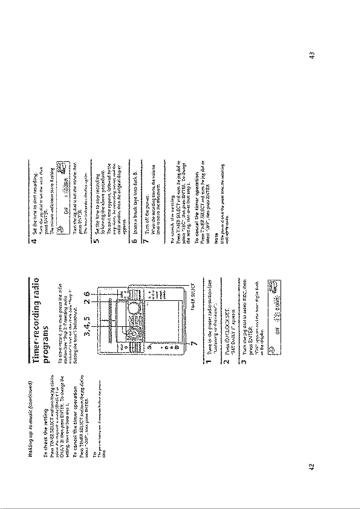
FRONT PANEL SECTION
1
wire (flat type) (21 core)
(CN601)
8
two claw
7
three screws
(BVTP 3
2
wire (flat type) (11 core)
(CN1001)
×
8)
5
screw (BVTT 3 × 8)
(FR1: AEP, UK, German)
8
two claw
6
lug
(FR1: AEP, UK, German)
4
connector
(CN403)
3
wire (flat type) (15 core) (EXCEPT FR1: SP)
wire (flat type) (19 core ) (FR1: SP)
(CN102)
DOOR ASS’Y
1
two screws
(PTPWH 2.6
×
6)
3
A
Remove the door ass’y
to direction of the
arrow
A
.
2
Open the door ass’y
– 26 –
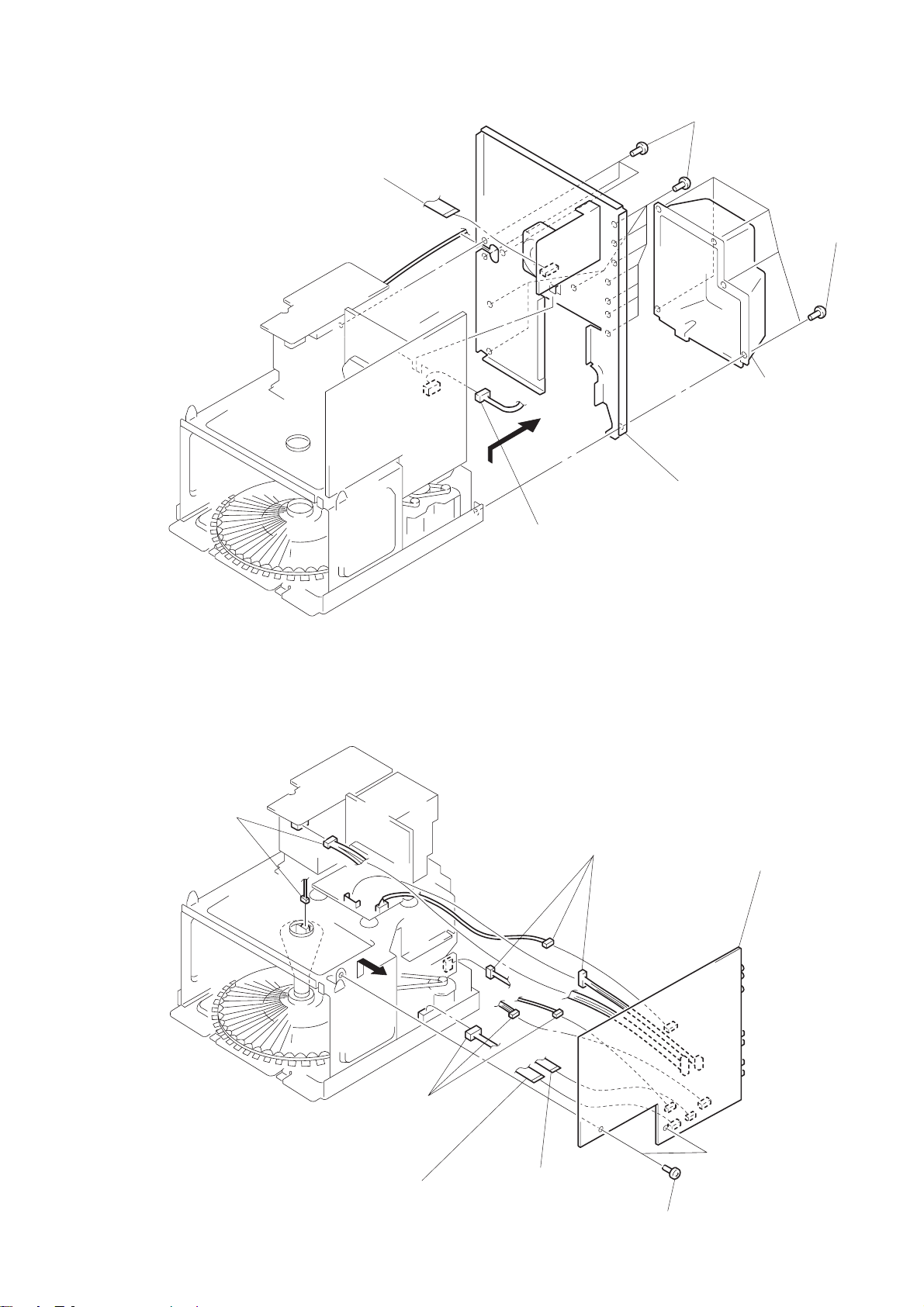
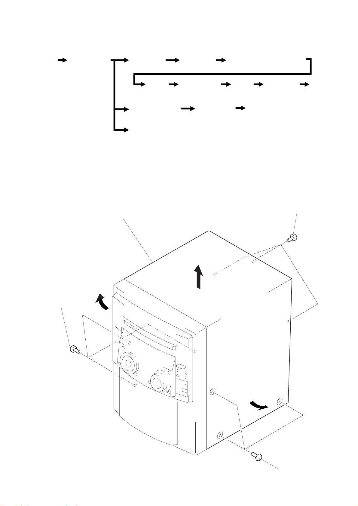
BACK PANEL
1
wire (flat type) (13 core) (F50/F100/FR1: E, AUS)
wire (flat type) (15 core ) (FR1: AEP, UK, G, SP)
(CN1)
2
connector
(CN 105)
5
thirteen screws
(BVTP 3
6
Remove the back panel
to direction of the arrow.
×
4
8)
3
cover
five screws
(BVTP 3
×
8)
MAIN BOARD
3
two connectors
(CN901, 904)
3
threeconnectors
(CN61, 451, 453)
3
threeconnectors
(CN54, 202, 802)
5
Remove the MAIN
board to direction
of the arrow.
1
wire (flat type) (16 core)
(CN401)
2
wire (flat type) (9 core)
(CN402)
– 27 –
4
two screws
(BVTP 3
×
8)
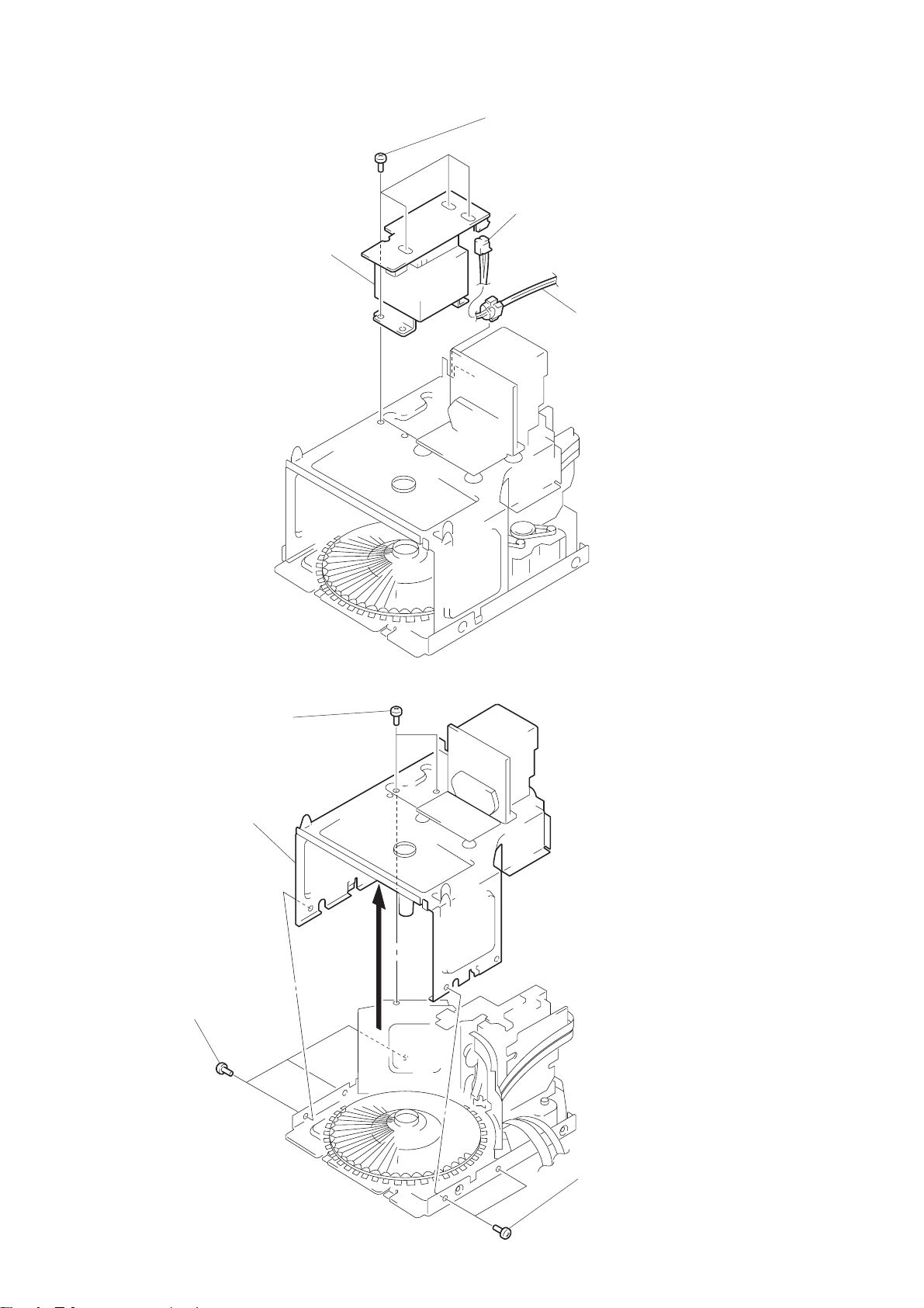
POWER TRANSFORMER (T901)
4
power transformer
(T901)
3
four screws
(BVTT 3
1
×
8)
connector
(CN903)
2
power cord
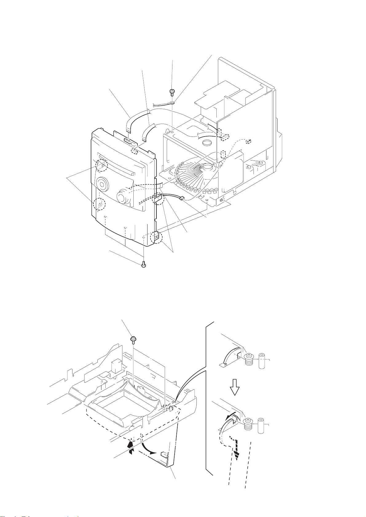
SUB CHASSIS
2
1
3
sub chassis
three screws
(BVTP 3
×
8)
two screws
(BVTT 3
×
8)
– 28 –
2
two screws
(BVTP 3
×
8)
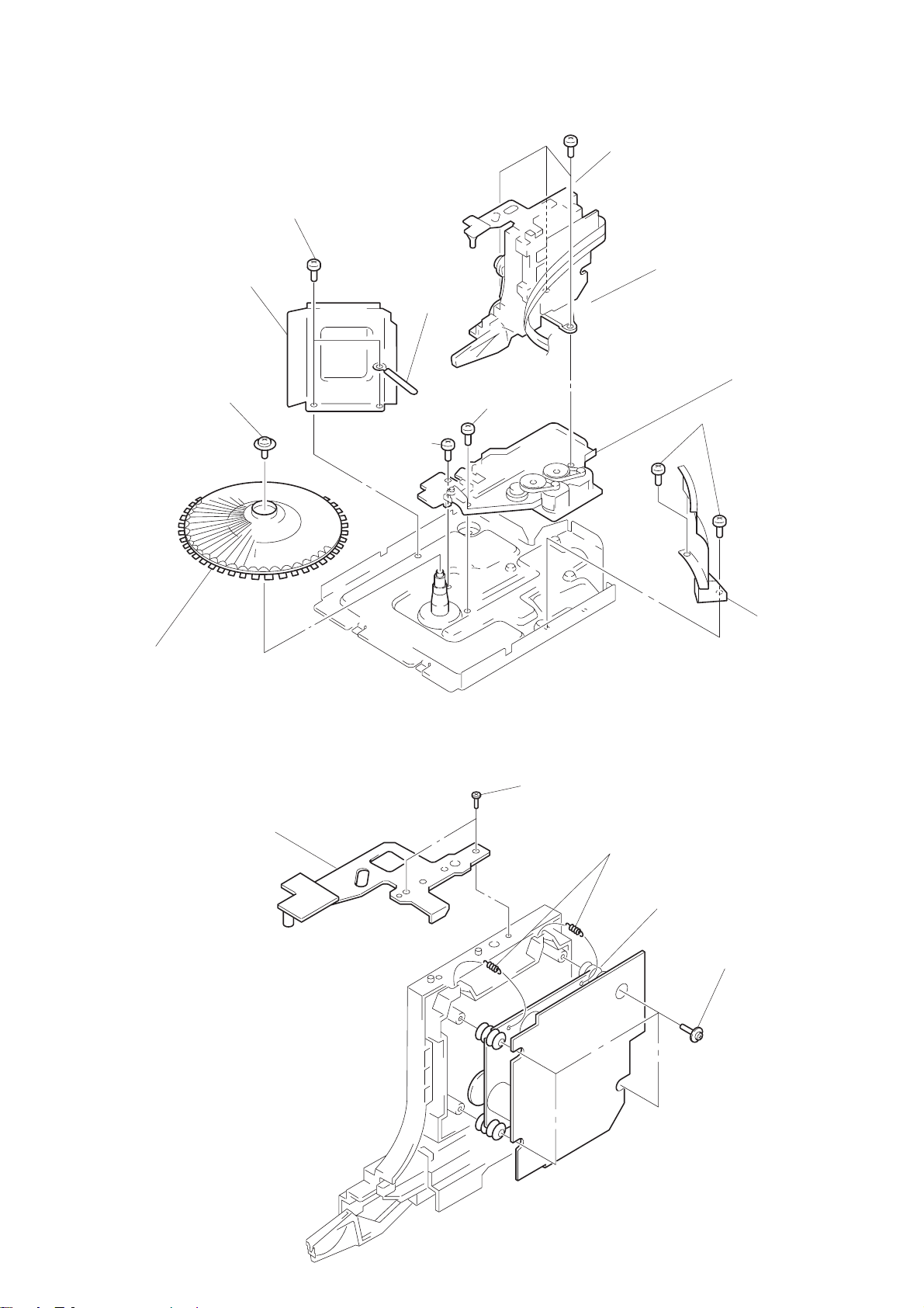
CD MECHANISM DECK SECTION
5
two screws
7
1
screw
(PTPWH 2.6
reinforcement
×
8)
(BVTT 3
×
6)
!º
screw
(BVTP 3
6
wire holder
×
14)
!¡
screw
(BVTT 3
8
three screws
(BVTT 3
×
10)
×
10)
9
base (LOADING)
3
two screws
(BVTP 3
!™
base (CDM)
×
8)
2
table (S0)
BASE UNIT
2
bracket
1
two screws
(BTP 2.6
×
8)
3
two tention springs
5
base unit
4
4
four screws
(PTPWH 2.6
cover (CD)
×
8)
– 29 –
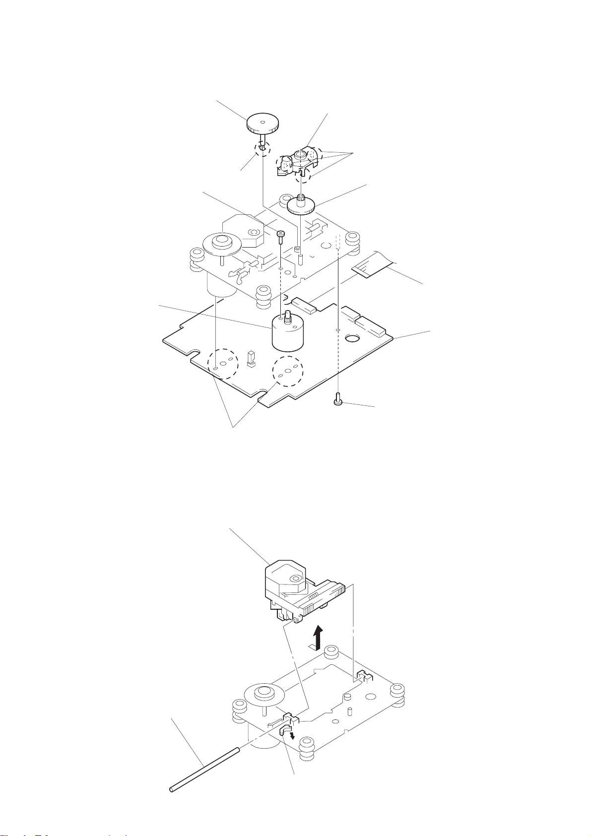
BD BOARD, SLED MOTOR (M102)
6
gear (A) (S)
!º
two screws
(2
×
3)
!¡
sled motor
(M102)
5
claw
8
gear cover
7
three claws
9
gear (B) (RP)
1
wire (flat type) (16 core)
(CN101)
4
BD board
OPTICAL PICK-UP (KSS-213B/S-N)
3
Remove the optical
pick-up to direction
of the arrow
3
Removal
four solders.
A
.
A
2
screw
(B 2
×
5)
sled shaft
2
– 30 –
1
claw
 Loading...