


Digital Wireless
4-739-796-01 (1)
Transmitter
Operating Instructions
DWT-B03R
© 2018 Sony Corporation

Table of Contents
Features ...................................................................... 3
Parts Identification ................................................... 4
Power Supply ............................................................. 5
Inserting the Battery .............................................. 5
Removing the Battery ............................................ 5
Charging the Battery .............................................. 6
Setting the Transmission Channel ........................... 7
Selecting the Frequency Band, Group, and
Channel ................................................................ 7
Using Cross Remote .................................................. 8
Pairing .................................................................... 8
Using the Encrypted Transmission Function ......... 9
Using the Encryption Key Modes (SECURE
KEY / AES256) ................................................... 9
Using the Password Mode (PASSWORD) .......... 10
Basic Menu Operations .......................................... 10
Menu Settings .......................................................... 11
Unit Name Setting (NAME) ................................ 11
Frequency Band Selection (BAND) .................... 11
Group Selection (GROUP) .................................. 12
Channel Selection (CH) ....................................... 12
Audio Attenuator Setting
(AF ATT) ........................................................... 12
Low-Cut Filter Setting (LCF) .............................. 12
Lock Function (LOCK) ....................................... 12
Power Save Setting (POWER SAVE) ................. 13
Cross Remote (RF REMOTE) ............................. 13
Receiver Search Function (SEARCH RX) .......... 13
Audio Codec Mode Setting (CODEC MODE) ... 13
Encrypted Transmission Function Setting
(ENCRYPTION) ............................................... 13
Audio Input Level Setting
(INPUT LEVEL) ............................................... 13
Audio Phase Switch Function (AF PHASE) ....... 14
Internal Signal Generator Function (INTERNAL
SG) ..................................................................... 14
Transmission Power Setting (RF POWER) ......... 14
Maximum Transmission Power Setting (MAX RF
POWER) ............................................................ 14
Total Usage Time Display (TIME) ...................... 14
Remaining Battery Indicator Setting (BATTERY
REMAIN) .......................................................... 14
Display Brightness Setting (BRIGHTNESS) ...... 15
Automatic Display Dimmer Setting (DISPLAY
DIMMER) .......................................................... 15
LED Brightness Setting (LED DIMMER) .......... 15
Settings Storage Function (USER MEMORY) ... 15
Factory Settings Restoration (FACTORY
PRESET) ........................................................... 15
Software Version Display (VERSION) ............... 16
Attaching the Belt Clip ........................................... 16
Block Diagram ......................................................... 17
Troubleshooting ....................................................... 18
Important Notes on Operation .............................. 20
Operation and Storage ......................................... 20
Cleaning ............................................................... 20
Notes on Simultaneous Multi-Channel
Operation ........................................................... 20
Notes on Use with Microphones .......................... 20
CROSS REMOTE Compatibility ........................ 20
Notes on Accessories ........................................... 21
Notes on the Battery ............................................ 21
Notes on Drip Resistance ..................................... 21
Specifications ........................................................... 22
Main Unit ............................................................. 22
NP-BX1 Rechargeable Battery Pack ................... 22
Carrier Frequencies and Channel Steps ............... 24
2

Features
The DWT-B03R is a drip-resistant digital wireless
transmitter featuring a highly durable yet compact and
lightweight design. The unit is suitable for broadcast and
ENG (electronic news-gathering) applications, as well as
for musical and television video production.
What is DWX?
DWX refers to Sony’s new digital wireless microphone
system. The DWX series reflects Sony’s extensive
expertise in professional microphones and sound design. It
represents a successful blend of Sony know-how, wireless
technology renowned for stability, and cutting-edge digital
audio technology.
In addition to realizing the high sound quality possible
with a digital system, the DWX series supports multichannel simultaneous operation, encrypted transmission,
and metadata transmission for monitoring the status of
multiple transmitters. Using a main link and a separate
additional link, remote control of transmitters from the
receiver is also possible. With its many advanced features,
the system has the potential to revolutionize the workflow
of professional applications.
High drip resistance against sweat, rain,
and sprays
The inside of the unit’s casing includes packing, and the
unit’s connectors are drip resistant. These features provide
the unit with a drip resistance equivalent to IPX4/IPX5
(according to Sony test conditions).
Lithium-ion battery for extended use
The NP-BX1 rechargeable battery pack (supplied) allows
extended operation times of up to about 7 hours.
Simultaneous multi-channel operation
Simultaneous multi-channel operation is made possible
with the 375-kHz interval channel plan.
Encrypted transmissions
AES 256-bit encryption allows for highly secure wireless
transmissions.
Support for a wide range of audio input
levels
For details, see “Audio Input Level Setting (INPUT
LEVEL)” (page 13).
What is WiDIF-HP?
WiDIF-HP (WiDIF: Wireless Digital Interface Format,
HP: High Profile) is a wireless digital audio interface
format developed by Sony.
It enables highly secure transmission with high sound
quality and low system latency, and supports simultaneous
multi-channel operation.
What is Cross Remote?
Cross Remote is a system that allows transmitters to be
monitored and controlled from a receiver and the Wireless
Studio control software installed on a computer connected
to the receiver.
For example, the settings of a transmitter worn under
clothing can be easily changed over the wireless link.
Compact and lightweight design
The unit is equipped with a magnesium-alloy casing,
providing a body that is durable in addition to being
compact and lightweight.
High sound quality and low latency
Low system latency of 1.2 ms is achieved when using
codec MODE2.
Switch between four audio codec modes based on your
operational needs.
For details, see “Audio Codec Mode Setting (CODEC
MODE)” (page 13).
Switchable RF output power
For details, see “Transmission Power Setting (RF
POWER)” (page 14) and “Maximum Transmission Power
Setting (MAX RF POWER)” (page 14).
Digital low-cut filter
For details, see “Low-Cut Filter Setting (LCF)”
(page 12).
Audio phase switch function
For details, see “Audio Phase Switch Function (AF
PHASE)” (page 14).
Power sleep mode
For details, see “Power Save Setting (POWER SAVE)”
(page 13).
User settings function
For details, see “Settings Storage Function (USER
MEMORY)” (page 15).
Organic EL (electroluminescent) display
The quick response of the OLED (organic light-emitting
diode) display enables real-time operating conditions to be
displayed clearly and accurately.
3
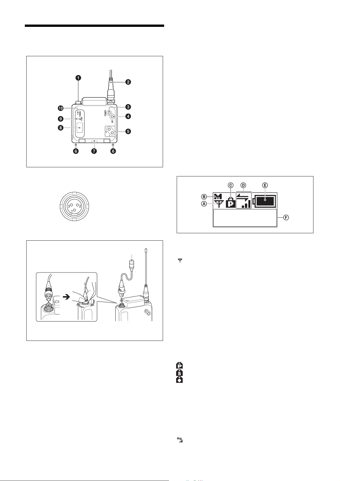
Parts Identification
a Audio input connector (mini 3-pin with lock)
Connects to a lavalier microphone.
e + and – buttons
Selects the functions or values shown on the display.
Holding down the – button while turning the unit on
activates the pairing operation for the wireless remote
control function.
f Battery charger connector
Connects to the BC-DWX1 battery charger (not supplied),
and allows you to charge the lithium-ion battery inserted in
the unit.
g Battery compartment cover
Insert the NP-BX1 rechargeable battery pack (supplied)
here.
For safety, use only the Sony battery packs and AC
adaptors listed below.
•NP-BX1
For details on how to insert batteries, see “Power Supply”
(page 5).
h Display
1: GND
2: +5.2 V (output)
3: Hot +5.2 V
Connecting the microphone
Microphone
To secure the connection, turn the ring on the
connection plug to lock it.
b Antenna
c POWER button
Turns the unit on or off.
Hold down the button for 1 second or longer to turn the
unit on. To turn the unit off, hold down the button until the
POWER indicator turns off.
d SET button
Allows you to adjust the displayed function settings and
apply the adjusted values.
Holding down the SET button while turning the unit on
turns the unit on without sending a signal.
NAME
DWT-B03R
A RF transmission indicator
Indicates the current transmission status.
: Currently transmitting.
– : RF transmission stopped.
B RF transmission power indicator
Indicates the current transmission power setting. You can
change the setting with the RF transmission power setting
function.
H: Transmitting at 25 mW.
M: Transmitting at 10 mW.
L: Transmitting at 2 mW.
C Lock indicator
Indicates whether the accidental operation locks are
enabled. Nothing is displayed when the lock function is
disabled.
: Operation of the POWER button is locked.
: Changes to the settings are locked.
: Operation of the POWER button and changes to the
settings are locked.
For details, see “Lock Function (LOCK)” (page 12).
D Cross Remote condition indicator
Indicates the signal transmission condition of the wireless
remote control function (4 levels).
: Good transmission.
4
: Somewhat good transmission.
: Somewhat poor transmission.
: Poor transmission.
: Unable to communicate with paired receiver.
When the wireless remote control function is disabled, this
indicator does not appear.
Power Supply
The unit can operate on the lithium-ion battery
continuously for about 7 hours at 25 °C (77 °F).
E Remaining battery indicator
Indicates the remaining battery charge.
For details, see “Remaining battery indicator” (page 6).
F Menu display area
Displays the status of the various functions. To cycle
through the functions, press the + and – buttons.
For details, see “Menu Settings” (page 11).
i AF (audio input level) / PEAK indicator
Lights green when the audio signal input is stronger than
the reference level.
Lights red as a warning of excessive input when the audio
signal input is 3 dB below the level at which distortion
begins.
j POWER indicator
Lights green when the unit is turned on. This blinks when
the battery charge is low.
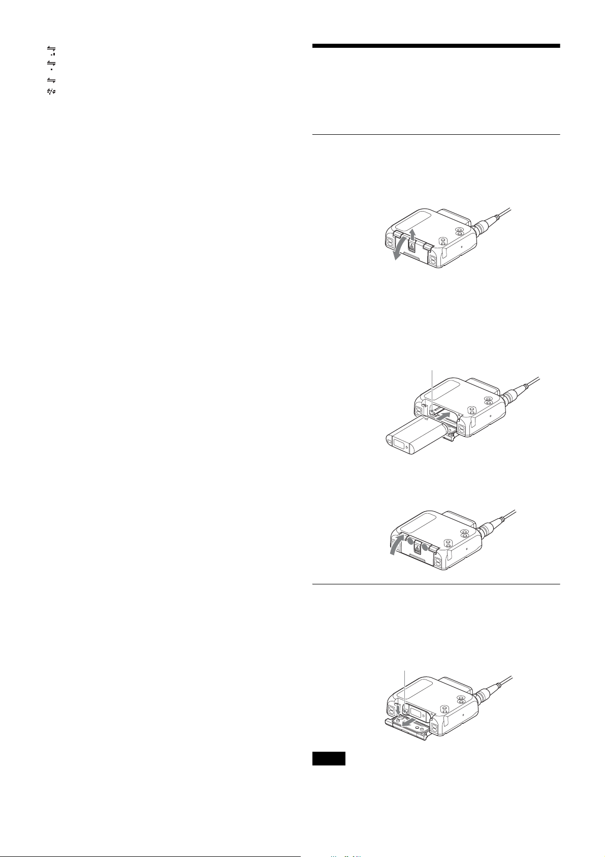
Inserting the Battery
1
Slide the tab at the center of the unit’s bottom, and pull
the battery compartment cover outward to open it.
2
Insert the lithium-ion battery while holding down the
lock lever with the battery’s edge until the battery is
fully inserted and locked into place.
Be sure to check that the lithium-ion battery is oriented
correctly beforehand.
Lock lever
3
Press both sides of the tab at the bottom of the unit to
close the battery compartment cover.
Removing the Battery
Open the battery compartment cover, and shift the lock
lever to remove the battery.
Be careful not to drop the battery.
Lock lever
Notes
• To prevent dirtying of the terminals, short circuits, or
other problems, place the removed battery in a plastic
5
bag, for example, and keep it away from metal objects
during transport or storage.
• The battery will slowly discharge, even when the unit is
turned off. Remove the battery from the unit before
extended periods of disuse.
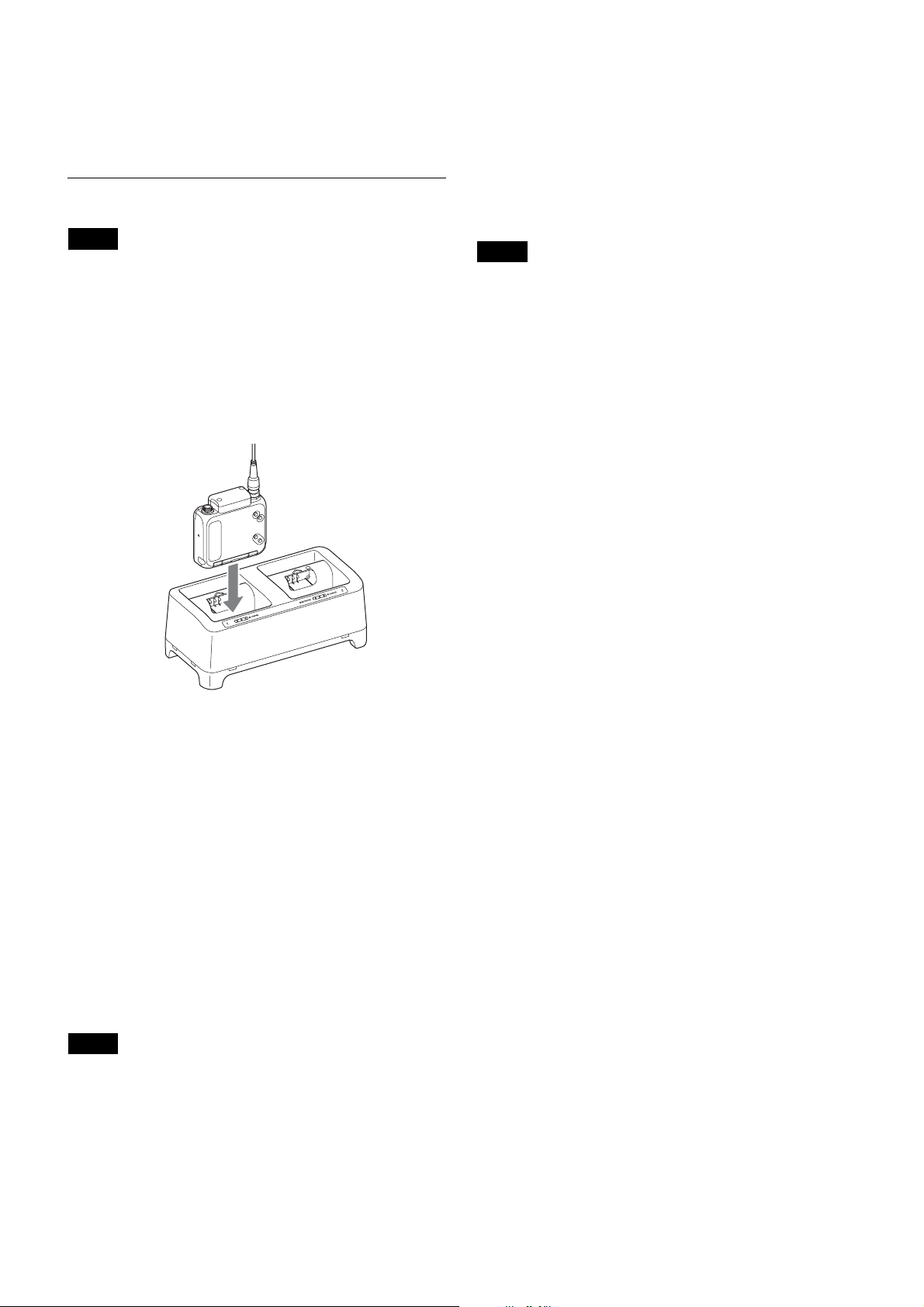
Charging the Battery
Notes
• Be sure to charge the battery before using the unit for the
first time.
• A charged battery will slowly discharge, even when it is
not in use. Be sure to charge the battery before each use
to ensure safe operation.
Use the BC-DWX1 battery charger to charge the battery
while it is inserted in the unit.
Insert the unit fully into the charging port on the BCDWX1.
off, and never touch the terminals directly with your
hands.
• Always use genuine Sony lithium-ion batteries.
Remaining battery indicator
Indicates the remaining battery charge.
Replace the battery with a charged battery when the
remaining battery indicator starts to blink.
Notes
• If you intend to use the unit continuously for an extended
period, we recommend replacing the battery with a fully
charged battery.
• The indicator may not be correct depending on your
operating environment.
• The unit is designed to operate for at least 30 minutes
after the remaining battery indicator starts to blink, but it
may operate for longer in optimal environments.
For details on charging, refer to the BC-DWX1 battery
charger’s operating instructions.
Charging time
Fully charging a fully discharged NP-BX1 rechargeable
battery pack (supplied) inserted in the unit in an ambient
temperature of 25 °C (77 °F) will take about 3 hours.
The charging time may be longer depending on your
operating environment. In addition, battery packs that have
not been used for extended periods may take longer to
charge.
When you are in a hurry
If necessary, devices can be removed from the unit before
they are fully charged. However, their usable durations
will vary depending on how long they were charged.
Notes
• If you insert the unit into the BC-DWX1 while the unit
is turned on, the unit will turn off, but charging will still
occur. The unit will remain turned off, even after you
remove it from the BC-DWX1.
• Proper charging may not be possible if the battery
terminals or the unit’s charging terminals are dirty. In
such cases, wipe the terminals with a dry cloth or cotton
swab. When doing so, make sure that the unit is turned
6

Setting the Transmission Channel
The unit provides groups of interference-free channels.
When using multiple wireless microphones and
transmitters at the same time (simultaneous multi-channel
operations) within the same area, you must use channels
within the same group to prevent signal interference.
To set the transmission channel on the unit, first select the
frequency band, group, and channel on the receiver using
its RF indicator and scanning functions, then match the
frequency band, group, and channel settings on the unit
with the settings on the receiver.
Notes
• Certain transmission channels cannot be used with the
wireless remote control function.
For details on transmission channels that support the
wireless remote control function, refer to “Sony Digital
Wireless Microphone System Frequency Lists” on the
supplied CD-ROM.
• When selecting the channel, “(INCOMPATIBLE WITH
RF REMOTE)” will slide across the display for
transmission channels that cannot be used with the
wireless remote control function.
• When a transmission channel that cannot be used with
the wireless remote control function is selected,
“RESTRICTED BY GP/CH SETTING” appears on the
RF REMOTE screen and the wireless remote control
function cannot be used. To enable use of the wireless
remote control function, select transmission channels for
which “(INCOMPATIBLE WITH RF REMOTE)” does
not appear during channel selection.
3
Hold down the SET button until the setting value
blinks.
4
Use the + and – buttons to select the frequency band.
5
Press the SET button to confirm.
6
Use the + and – buttons to display the GROUP screen.
7
Hold down the SET button until the setting value
blinks.
8
Use the + and – buttons to select the group.
9
Press the SET button to confirm.
10
Use the + and – buttons to display the CH screen.
11
Hold down the SET button until the setting value
blinks.
12
Use the + and – buttons to select the channel.
13
Press the SET button to confirm.
Notes
To start signal transmission with the selected frequency
band, group, and channel, turn off the unit and then turn it
on again.
Configuring the settings via Cross Remote
pairing
When the unit is paired with the receiver, the unit’s
transmission channel is automatically set to the receiving
channel on the receiver.
For details on pairing, see “Pairing” (page 8).
Selecting the Frequency Band,
Group, and Channel
Set the frequency band (BAND), group (GROUP), and
channel (CH) as follows.
For details on groups and channels, refer to “Sony Digital
Wireless Microphone System Frequency Lists” on the
supplied CD-ROM.
For details on menu operations, see “Basic Menu
Operations” (page 10).
Notes
These settings cannot be changed during actual signal
transmission.
1
Turn the unit off, and then hold down the POWER
button while pressing the SET button.
The unit turns on with signal transmission stopped.
2
Use the + and – buttons to display the BAND screen.
7

Using Cross Remote
The unit is equipped with a wireless remote control
function that allows the unit’s settings (low-cut filter,
attenuation controls, power controls, etc.) to be controlled
from the receiver or other devices. This makes it easier to
operate and manage the microphone system while in the
field.
The IEEE802.15.4-compliant wireless remote control
function uses the 2.4- GHz band and has no effect on the
RF band of digital wireless audio.
The function is activated when the unit is paired with the
receiver via the RF REMOTE function.
Pairing must be performed before the wireless remote
control function can be used.
Notes
If “RESTRICTED BY GP/CH SETTING” appears on the
RF REMOTE screen, the wireless remote control function
cannot be used. To enable use of the wireless remote
control function, select a different transmission channel.
For details on changing the transmission channel, see
“Setting the Transmission Channel” (page 7).
Pairing
Pairing links the unit to the receiver that will control the
unit via the wireless remote control function.
Pairing will start automatically if pairing mode is enabled
on the receiver side and you turn on the unit by holding
down the POWER button while pressing the – button on
the unit.
RF REMOTE function is enabled and remote control
is possible.
Using Cross Remote with a previous
pairing setting
Set the RF REMOTE screen setting value to ON.
Notes
• When RF REMOTE is set to ON, communication will be
established with the previously paired receiver. To use
the wireless remote control function with a different
receiver, perform the pairing procedure again with the
target receiver.
• Multiple instances of the unit cannot be paired with the
same receiver.
• Resetting the unit to factory settings using the
FACTORY PRESET function (page 15) clears any
pairing with a receiver.
Unit operations that can be performed via remote
control
• Unit name setting
• Frequency band, group, and channel selection
• RF transmission power setting
• MIC/LINE setting and attenuator setting for the audio
input level
• Low-cut filter setting
• Power save setting
• Total usage time reset
• Audio codec mode setting
• Internal signal setting
• Lock setting
• Remaining battery indicator setting
For details on the settings, see “Menu Settings” (page 11).
To perform pairing manually via the settings menu,
perform the following.
1
Enable paring mode on the receiver that will be
controlling the unit.
For details, refer to the receiver’s operating
instructions.
2
Use the + and – buttons to display the RF REMOTE
screen.
3
Hold down the SET button until the setting value
blinks.
4
Use the + and – buttons to select PAIRING.
5
Press the SET button to confirm.
The unit sends a pairing request to the receiver on
which pairing mode is enabled.
If you press any button on the unit before pairing is
complete, pairing mode will be canceled.
When communication with the receiver is established,
the condition indicator ( ) rises, indicating that the
To perform remote control, the receiver must be equipped
with a control function for the target setting for control.
For details, refer to the receiver’s operating instructions.
Stopping Cross Remote
Set the RF REMOTE screen setting value to OFF.
Notes on Cross Remote
As the unit’s wireless remote control function uses the 2.4GHz band, it may be subject to interference from other
devices.
• If pairing fails (i.e., “Pairing fail” is displayed), perform
pairing again.
In such cases, communication between the transmitter
and receiver may not have been established within the
predetermined amount of time.
Pairing may be hindered if another receiver is engaged in
pairing nearby.
• Unstable remote control may be resolved by disabling
and reenabling the wireless remote control function in
the RF REMOTE screen, then reestablishing connection
with the transmitter (i.e., changing to a channel with less
interference).
8
 Loading...