

Page 1
WirelessAdapter
3-874-379-02(1)
Printed in Japan
DWA-01D
お買い上げいただきありがとうございます。
電気製品は安全のための注意事項を守らないと、
火災や人身事故になることがあります。
この取扱説明書には、事故を防ぐための重要な注意事項と製品の
取り扱いかたを示してあります。この取扱説明書をよくお読みの
うえ、製品を安全にお使いください。お読みになったあとは、
いつでも見られるところに必ず保管してください。
© 2008 Sony Corporation
取扱説明書 ______________
Operating Instructions_____
Mode d’emploi ___________
Bedienungsanleitung _____
Istruzioni per l’uso ________
Manual de instrucciones___
S
JP
GB
FR
DE
IT
ES
Page 2
日本語
安全のために
ソニー製品は安全に十分に配慮して設計されています。
しかし、電気製品はまちがった使いかたをすると、火災
や感電などにより死亡や大けがなど人身事故につながる
ことがあり、危険です。
事故を防ぐために次のことを必ずお守りください。
安全のための注意事項を守る
4 〜 5 ページの注意事項をよくお読みください。
定期点検を実施する
5 年に 1 度くらいは内部の点検について、お買い上げ店
またはソニー
の業務用商品相談窓口にご相談ください。
故障したら使用を中止する
お買い上げ店またはソニーの業務用商品相談窓口にご連絡く
ださい。
万一、異常が起きたら
• 異常な音、におい、煙が出たら
• 落としたら
m
aDC 電源ケーブル、およびすべての接続ケーブルを抜
く。
b お買い上げ店またはソニーの業務用商品相談窓口に修
理を依頼する。
警告表示の意味
取扱説明書および製品で
は、次のような表示をし
ています。表示の内容を
よく理解してから本文を
お読みください。
この表示の注意事項を守
らないと、火災や感電な
どにより死亡や大けがな
ど人身事故につながるこ
とがあります。
この表示の注意事項を守
らないと、感電やその他
の事故によりけがをした
り周辺の物品に損害を与
えたりすることがありま
す。
注意を促す記号
炎が出たら
m
DC 電源ケーブルを抜き、消火する。
2
行為を禁止する記号
行為を禁止する記号
Page 3

目次
警告 ...............................................................................4
注意 ...............................................................................4
その他の安全上のご注意....................................................5
概要 ....................................................................................6
各部の名称と働き...............................................................6
前面 / 後面 / 側面.................................................................... 6
底面 ......................................................................................... 7
取り付けと接続 ..................................................................9
レシーバー / チューナーユニットを取り付ける..................... 9
カムコーダーへ取り付ける / 取り外す ................................... 9
2 台の DWA-01D を連結する ................................................ 11
ブロックダイヤグラム......................................................12
故障かなと思ったら .........................................................13
使用上のご注意 ................................................................15
使用・保管 ............................................................................ 15
お手入れ ................................................................................ 15
主な仕様 ...........................................................................15
保証書とアフターサービス ..............................................16
保証書.................................................................................... 16
アフターサービス.................................................................. 16
目次
JP
3
Page 4
指定の電圧および極性
で使用する
規定外の電圧および極性で
使用すると、火災の原因と
なることがあります。
この取扱説明書に記されて
いる電圧および極性で使用
してください(10 ページ参
照)。
指定された DC 電源
ケーブルを使用する
指定以外の DC 電源ケーブ
ルを使用すると、火災や感
電の原因となります。
雨のあたる場所や、油
煙、湯気、湿気、ほこ
りの多い場所では使用
しない
上記のような場所や、この
取扱説明書に記されている
仕様条件以外の環境で使用
すると、火災や感電の原因
となることがあります。
指定以外の金具、ネジ
は使わない
指定以外の金具やネジを使
用すると、火災や感電の原
因となることがあります。
スロットインレシー
バー取り付け時には、
ネジを確実に締める
この取扱説明書に記載され
た方法(9 ページ参照)で
しっかり取り付けないと、
故障やけがの原因となるこ
とがあります。
スロットインレシー
バー取り付け時には、
指挟みに注意する
注意を払わずに取り付けを
行うと、指を挟み、けがの
原因となります。
使用時は周囲の状況に
注意をはらう
周囲の状況を把握しないま
ま使用すると、事故やけが
などの原因となります。
/
注意
4
警告
Page 5
スロットインレシー
バー挿入時には、異物
混入がないかどうか確
認する
異物が入ると、火災や感電
の原因となることがありま
す。
DC 電源ケーブルを傷
つけない
DC 電源ケーブルを傷つける
と、火災や感電の原因とな
ります。
• DC 電源ケーブルを加工し
たり、傷つけたりしない。
• 重いものをのせたり、
引っ張ったりしない。
• 熱器具に近づけたり、加
熱したりしない。
• DC 電源ケーブルを抜くと
きは、必ずコネクターを
持って抜く。
万一、DC 電源ケーブルが傷
んだら、ソニーの
相談窓口
さい。
に交換をご依頼くだ
業務用商品
その他の安全上の
ご注意
イヤホンやヘッドホンを使用するとき
は、音量を上げすぎないようにご注意く
ださい。
耳を刺激するような大きな音量で長時間
続けて聞くと、聴力に悪い影響を与える
ことがあります。
分解や改造をしない
分解や改造をすると、感電
の原因となることがありま
す。
電源の ON/OFF 時に
は、ヘッドホンのボ
リュームを絞る
電源の ON/OFF 時には大き
な雑音が発生し、聴力に悪
い影響を与えることがあり
ます。
その他の安全上のご注意
5
Page 6
概要
各部の名称と働き
DWA-01D は、別売りのデジタルワイヤ
レスレシーバー DWR-S01D や UHF シン
セサイザーチューナーユニット WRR855 をソニー製カムコーダーに取り付け
たり、ポータブルワイヤレスレシーバー
として使用するためのアダプターです。
豊富な音声出力
DWR-S01D の性能を十分に発揮すること
ができる豊富な出力機能を搭載。アナロ
グ出力だけでなく AES/EBU デジタル出
力も装備。さらにワードシンク入力も装
備し、さまざまなシステムへの対応が可
能です。
モニター出力を装備
音声出力の簡易確認に便利なモニター出
力を装備。
連結機構を採用
本機 2 台を付属の金具で連結し、それぞ
れに DWR-S01D を装着することにより、
4 チャンネルレシーバーとして使用でき
ます。
前面/後面/側面
防滴構造
DWR-S01D や WRR-855 を本機に装着す
ることにより、JIS 防滴Ⅱ型
造になります。
* JIS 防滴Ⅱ型:鉛直方向から 15 度の範囲で落
ちてくる水滴によって有害な影響のないもの。
概要/各部の名称と働き
6
*
の防滴構
Page 7

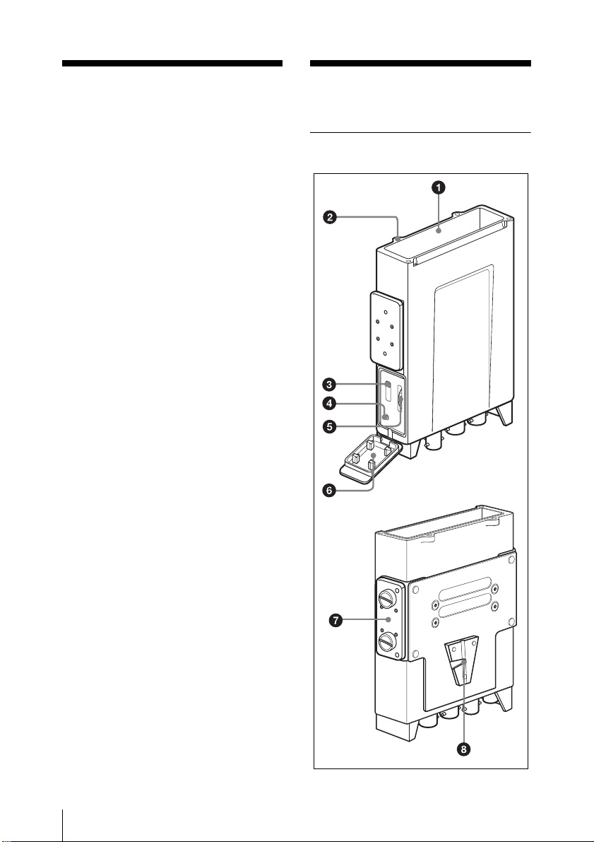
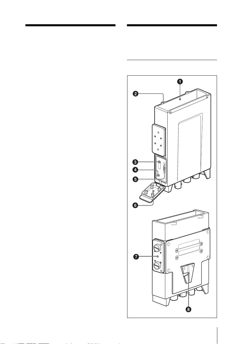
a ワイヤレスレシーバースロット
別売りの DWR-S01D や WRR-855 を装着
します。
◆ 装着方法については、「レシーバー / チュー
ナーユニットを取り付ける」(9 ページ)をご
覧ください。
b ワイヤレスレシーバー装着ネジ穴
装着したワイヤレスレシーバーと本機を
固定します。
c モニター出力音声切り換えスイッ
チ
PHONES 端子からの音声を選択します。
1:OUTPUT1 端子の音声を L/R 両チャ
ンネルに出力します。
1+2:OUTPUT1 端子の音声と、アナ
ログ出力に設定した場合の OUTPUT2
端子の音声をミックスし、L/R 両チャン
ネルに出力します。
2:アナログ出力に設定した場合の
OUTPUT2 音声を L/R 両チャンネルに
出力します。WRR-855 装着時は、音声
は出力されません。
e モニター音量調整つまみ
モニター出力の音量を調整します。
f 音声モニター部カバー
音声モニター部を保護するためのカバー
です。ヘッドホンを使用しない場合は、
カバーを閉めてご使用ください。
g 連結金具
本機 2 台を連結するための固定金具で
す。
◆ 連結方法については、「2 台の DWA-01D を連
結する」(11 ページ)をご覧ください。
h V マウント金具
カムコーダーに取り付けるための金具で
す。
底面
ご注意
モニター出力の信号は OUTPUT1/2 端
子へ出力されるアナログ信号を分岐して
出力するため、DWR-S01D の ANALOG
OUTPUT1 機能を使用して OUTPUT1
端子に出力する音声を変更した場合は、
その設定に従って音声が出力されます。
d
PHONES(モニター出力)端子
(3.5mmTRS ジャック、チップ:L、
リング:R、スリーブ:グランド)
ヘッドホンを接続します。出力される信
号は、モニター出力音声切り換えスイッ
チによって選択できます。
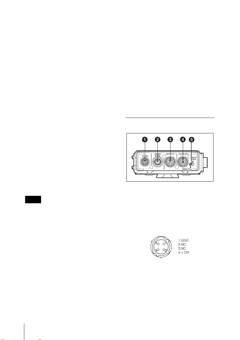
a DCIN(外部電源入力)端子(4 ピ
ン)
付属の DC 電源ケーブルを使って、カム
コーダーなどの外部電源出力端子に接続
します。DC10V から 17V までの電圧に
対応します。
各部の名称と働き
7
Page 8

b WORDSYNC(ワードシンク)入
力端子(BNC タイプ)
外部からの同期信号を入力します。
DWR-S01D 装着時は、同期信号を入力す
ることにより全体のオーディオシステム
に同期させて使用することができます。
同期動作のためには、DWR-S01D の
UTILITY メニューの SYNCSOURCE 画
面で AUTO または EXTERNAL を選択
します。
WRR-855 装着時は機能しません。
デジタル音声信号を出力します。
ANALOGAES/EBU 切り換えスイッチ
で出力方式を選択できます。ANALOG
AES/EBU 切り換えスイッチが
ANALOG に設定されている場合は、
TUNER2 の音声が出力されます。
WRR-855 装着時には機能しません。
◆ 同期信号の対応周波数については、DWRS01D の取扱説明書をご覧ください。
ご注意
DWR-S01D 側で 75Ω 終端を行った場合
でも、電源を切っている間はハイイン
ピーダンス入力になります。
c OUTPUT1(アナログ音声出力)
端子 (4 ピン)
バランスのアナログ音声信号を出力しま
す。
DWR-S01D 装着時は、出力するチュー
ナーを DWR-S01D の UTILITY メ
ニューで選択できます。工場出荷時は
TUNER 1の音声が出力されます。
WRR-855 装着時は、この端子からのみ
音声信号が出力されます。
e ANALOGAES/EBU 切り換えス
イッチ
DWR-S01D 装着時、OUTPUT2 端子か
ら出力する信号を選択します。
ANALOG:バランスの音声信号が出力
されます。
AES/EBU:AES3 フォーマットのデジ
タル音声信号が出力されます。
WRR-855 装着時には機能しません。
d OUTPUT2(アナログ / デジタル音
声出力)端子(4 ピン)
DWR-S01D 装着時、バランスのアナロ
グ音声信号または AES3 フォーマットの
各部の名称と働き
8
Page 9
取り付けと接続
2
ワイヤレスレシーバー装着ネジ(4
か所)をドライバーで締める。
ご注意
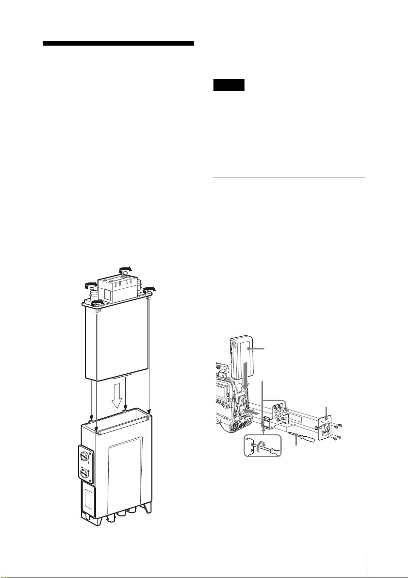
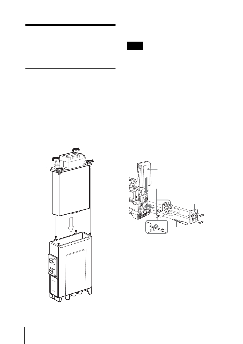
レシーバー / チューナー
ユニットを取り付ける
本機のワイヤレスレシーバースロットに
DWR-S01D や WRR-855 を取り付けま
す。
1
スロット内部の D-Sub15 ピン端子と
レシーバー / チューナーユニットの
D-Sub15 ピン端子の方向を合わせ
て、しっかり奥まで挿入する。
4か所のネジをしっかり締めていること
を確認してください。ネジが緩んでる
と、JIS 防滴Ⅱ型の性能が保てなかった
り、振動などにより動作不良の原因にな
ります。
カムコーダーへ取り付け
る / 取り外す
本機を使用して、ワイヤレスレシーバー
をソニー製カムコーダーの背面に装着で
きます。装着するには別売りのマウント
金具(A-8278-057-B)と、本機に付属の
マウントプレートが必要です。マウント
プレートから本機を外すには、プレート
の着脱レバーを押します。
バッテリーパック
BP-GL95/GL65/
L60S/L80S
(別売り)
マウント金具
(A-8278-057-B)(別売り)
マウントプ
レート(付属)
プラスドライバー
取り付けと接続
9
Page 10
電源を接続する
付属の DC 電源ケーブルで、本機の DC
IN 端子とカムコーダーの DCOUT 端子
を接続します。
オーディオケーブルを接続する
アナログオーディオのみのカムコー
ダーの場合
付属のオーディオケーブルで、本機の
OUTPUT1/2 端子とカムコーダーの
AUDIOIN 端子を接続します。
デジタルオーディオ入力に対応したカ
ムコーダーの場合
本機の ANALOGAES/EBU 切り換えス
イッチを AES/EBU に設定し、本機の
OUTPUT2 端子とカムコーダーの
AUDIOIN 端子を付属のオーディオケー
ブルで接続します。このときカムコー
ダーの AUDIOIN 端子の設定を AES/
EBU にしてください。
ワードクロックシンクとオー
ディオの接続
DWR-S01D を装着した本機と他の機種を
デジタルオーディオ接続して正しく運用
するためには、本機の AES/EBU 出力を
接続する機種にサンプリングレートコン
バーターが搭載されているか、本機の
WORDSYNC 入力端子にマスターワー
ドクロック信号を入力して同期する必要
があります。
マスタークロック信号を入力して同期す
るシステムには、次の 2 種類がありま
す。
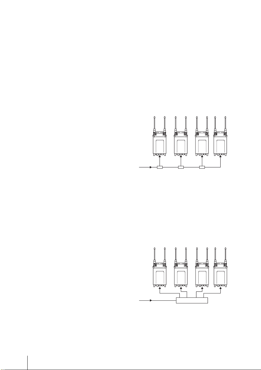
システム例1
マスターワードクロック信号を T 型
BNC 分岐端子で分配するシステムです。
いずれか一台を終端設定する必要があり
ます。
DWR-S01D で終端設定することも可能で
す。
◆ 終端設定の方法については、DWR-S01D の取
扱説明書をご覧ください。
75Ω 終端
OFF
マスターワードクロック
75Ω 終端
OFF
75Ω 終端
OFF
75Ω 終 端
ON
システム例2
マスターワードクロック信号を分配器で
分配し、それぞれの機器に接続するシス
テムです。全ての機器を終端設定しま
す。
75Ω 終端ON75Ω 終 端ON75Ω 終端ON75Ω 終端
ワードシンク分配器
マスターワードクロック
ON
10
取り付けと接続
Page 11
2 台の DWA-01D を連結
する
DWR-S01D を装着した本機 2 台を連結
し、4 チャンネルワイヤレスレシーバー
として使用することができます。
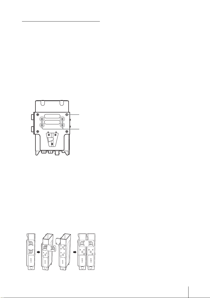
1
4 か所のネジを外し、V マウント金具
を取り外す。
外したネジは保管穴に取り付けてお
いてください。
ネジ
保管穴
2
連結金具のネジを緩めて外す。
3
外した金具を 90 度回転させ、金具の
穴と本体の突起を合わせて再度本体
に取り付ける。
4
2 台目の本機でも手順 1 〜 3 を行う。
5
2 台の本機を組み合わせ、金具のネ
ジを締めて固定する。
取り付けと接続
11
Page 12
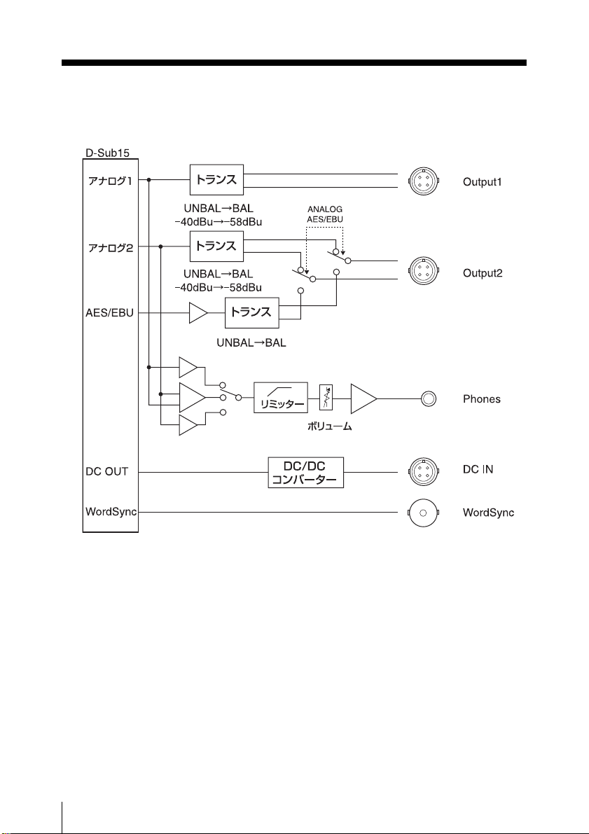
ブロックダイヤグラム
ブロックダイヤグラム
12
Page 13
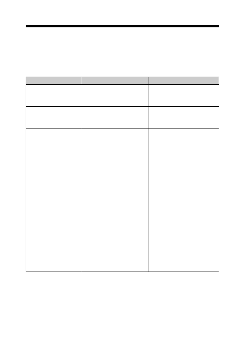
故障かなと思ったら
修理に出す前に、もう一度点検してください。それでも正常に動作しないときは、お買
い上げ店またはソニーのサービス窓口にお問い合わせください。
症状 原因 対策
DWR-S01D または WRR855 の電源が入らない。
アナログ接続時、
OUTPUT2 端子からノイ
ズが発生する。
アナログ接続時、
OUTPUT2 端子から音が
出ない。
デジタル接続時、
OUTPUT2 端子から音が
出ない。
デジタル接続時、接続し
た機器の音声にノイズが
入る。
DWR-S01D または WRR-855 が
本機にしっかり装着されていな
い。
ANALOGAES/EBU 切り換えス
イッチが AES/EBU 側になって
いる。
DWR-S01D のチューナー 2 側の
電源が入っていない。または
WRR-855 が装着されている。
ANALOGAES/EBU 切り換えス
イッチが ANALOG 側になって
いる。
本機と接続先の機器が同期運転
できていない。
WORDSYNC 端子が 75Ω 終端
されていない。
奥までしっかり装着し、レシー
バーの装着ネジでしっかり固定し
てください。
ANALOGAES/EBU 切り換えス
イッチを ANALOG 側にしてくだ
さい。
OUTPUT2 端子からはチューナー
2 の音声が出力されるのでチュー
ナー 2 の電源を入れてください。
WRR-855 はシングルチャンネル
レシーバーのため、OUTPUT2 端
子からは音声出力しません。
ANALOGAES/EBU 切り換えス
イッチを AES/EBU 側にしてくだ
さい。
接続先の機器が非同期入力(サン
プリングレートコンバーター入
力)に対応していない場合、ワー
ドクロックで同期運転する必要が
あります。
本機がエンドデバイスになってい
る場合や、ワードクロックマス
ターに本機が 1 台だけ接続されて
いる場合は、DWR-S01D のユー
ティリティーメニューで 75Ω 終
端する必要があります。
故障かなと思ったら
13
Page 14
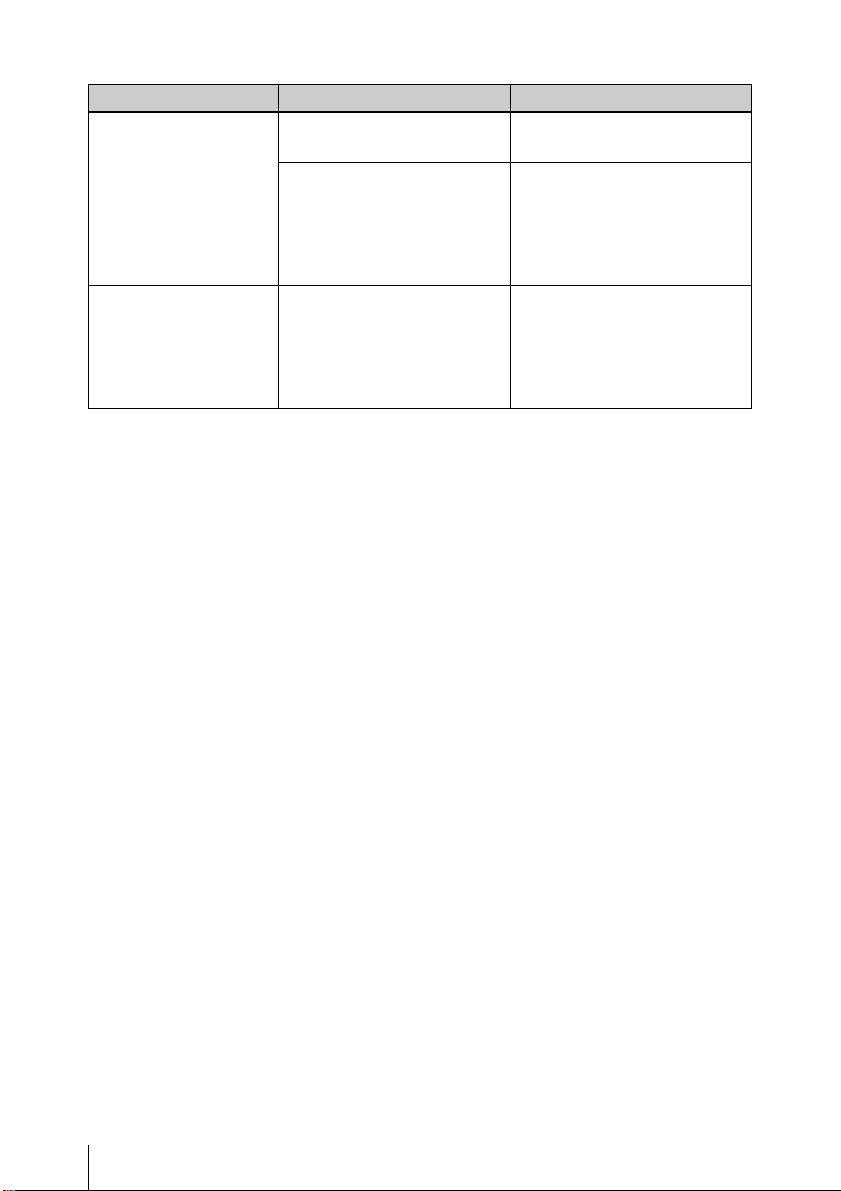
症状 原因 対策
モニター出力端子から音
がでない。
モニター出力音声切り換
えスイッチを 1 に設定し
ているのにチューナー 2
の音が混ざって聞こえる。
モニター音量調整つまみが絞ら
れている。
モニター出力音声切り換えス
イッチで音の出ないチューナー
を選択している。
DWR-S01D の ANALOG
OUTPUT1 機能が RX1+2 に設
定されている。
音量を調整してください。
DWR-S01D の電源スイッチを確
認してください。
WRR-855 はシングルチャンネル
レシーバーのため、チューナー 1
側のみの音声出力になります。
RX1 に設定してください。
RX1+2 に設定されていると、モ
ニター出力にチューナー 1 と
チューナー 2 の音声が混ざって出
力されます。
故障かなと思ったら
14
Page 15
使用上のご注意
使用・保管
• 本機は周囲温度 0 ℃〜 50 ℃の範囲で動
作します。
• 本機を電力機器(回転機、変圧器、調
光器等)に近接して使用すると、磁気
誘導を受けることがありますので、で
きるだけ離して使用してください。
お手入れ
• 水分やほこりの多い所、活性ガスにさ
らされる所で使用したあとは、早めに
コネクター部や本機表面のお手入れを
行ってください。お手入れを怠った
り、このような場所で長時間使用した
りすると、機器の寿命を縮めるおそれ
がありますので、ご注意ください。
• 表面やコネクター部の汚れは、乾いた
柔らかい布でふきとってください。シ
ンナーやベンジンなどの薬品類は、表
面の仕上げをいためますので使わない
でください。
主な仕様
オーディオ部
出力端子 SMC9-4S(凹)
(OUTPUT1/
OUTPUT2)
アナログ出力インピーダンス
150Ω 以下
AES/EBU 出力インピーダンス
110Ω
WORDSYNC 入力
BNC-R、75Ω(装着
した DWR-S01D に
て終端時)
モニター出力端子
φ3.5mmTRS ジャッ
ク
モニター出力レベル
50mW(16Ω 負荷、
T.H.D = 1%時)
一般
定格電源 DC12V
動作電圧 DC10 〜 17V
許容動作温度 0 ℃〜+ 50 ℃
許容保存温度 − 20 ℃〜+ 60 ℃
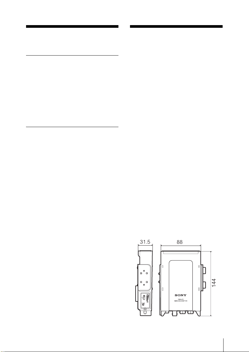
外形寸法図(単位:mm)
質量 約 330g
使用上のご注意/主な仕様
15
Page 16

付属品 DC 電源ケーブル(1)
マウントプレート(1)
オーディオケーブル
(2)
保証書(1)
取扱説明書(1)
それでも具合が悪いときは
お買い上げ店、または添付の「ソニー業
務用商品相談窓口のご案内」にあるお近
くのソニーサービス窓口にご相談くださ
い。
本機の仕様および外観は、改良のため予
告なく変更する場合がありますがご了承
ください。
お使いになる前に、必ず動作確認を
行ってください。故障その他に伴う営
業上の機会損失等は保証期間中および
保証期間経過後にかかわらず、補償は
いたしかねますのでご了承ください。
保証書とアフター
サービス
保証書
• この製品には保証書が添付されていま
すので、お買い上げの際お受け取りく
ださい。
• 所定の事項の記入および記載内容をお
確かめのうえ、大切に保存してくださ
い。
保証期間中の修理は
保証書の記載内容に基づいて修理させて
いただきます。詳しくは保証書をご覧く
ださい。
保証期間経過後の修理は
修理によって機能が維持できる場合、ご
要望により有料修理させていただきま
す。
保証期間中の修理など、アフターサービ
スについてご不明な点は、お近くのソ
ニー営業所にお問い合わせください。
アフターサービス
調子が悪いときはまずチェック
を
この説明書をもう一度ご覧になってお調
べください。
保証書とアフターサービス
16
Page 17
English
WARNING
Excessive sound pressure from earphones
and headphones can cause hearing loss.
In order to use this product safely, avoid
prolonged listening at excessive sound
pressure levels.
You are cautioned that any changes or
modifications not expressly approved in
this manual could void your authority to
operate this equipment.
For the customers in the U.S.A.
If you have any questions about this
product, you may call;
Sony Customer Information Service Center
1-800-222-7669 or
http://www.sony.com/
Declaration of Conformity
Trade Name: SONY
Model No.: DWA-01D
Responsible Party: Sony Electronics
Inc.
Address: 16530 Via Esprillo, San
Diego, CA 92127 U.S.A.
Telephone No.: 858-942-2230
For the customers in Europe
This product with the CE marking complies
with the EMC Directive issued by the
Commission of the European Community.
Compliance with this directive implies
conformity to the following European
standard:
• EN301489-1/9/17:
Electromagnetic compatibility and Radio
spectrum Matters (ERM)
Electromagnetic Compatibility (EMC)
This product is intended for use in the
following Electromagnetic Environments:
E1 (residential), E2 (commercial and light
industrial), E3 (urban outdoors), E4
(controlled EMC environment, ex. TV
studio).
The manufacturer of this product is Sony
Corporation, 1-7-1 Konan, Minato-ku,
Tokyo, Japan.
The Authorized Representative for EMC
and product safety is Sony Deutschland
GmbH, Hedelfinger Strasse 61, 70327
Stuttgart, Germany. For any service or
guarantee matters please refer to the
addresses given in separate service or
guarantee documents.
GB
This device complies with part 15 of the
FCC Rules. Operation is subject to the
following two conditions: (1) this device
may not cause harmful interference,
and (2) this device must accept any
interference received, including
interference that may cause undesired
operation.
All interface cables used to connect
peripherals must be shielded in order to
comply with the limits for Part 15 of FCC
Rules.
For the customers in Canada
Operation is subject to the following two
conditions: (1) this device may not cause
interference, and (2) this device must accept
any interference, including interference that
may cause undesired operation of the
device.
17
Page 18

Table of Contents
Features ................................................................................19
Parts identification ...............................................................19
Front/rear/side ................................................................19
Bottom ...........................................................................20
Attachment and connections ...............................................22
Attaching the receiver/tuner unit ...................................22
Attaching to/detaching from the camcorder ..................22
Combining two DWA-01D adapters .............................23
Block diagram ...................................................................... 25
Troubleshooting ................................................................... 26
Important notes on operation .............................................28
Notes on using the adapter .............................................28
On cleaning ....................................................................28
Specifications ........................................................................28
18
Table of Contents
Page 19
Features
The DWA-01D wireless adapter allows the
optional DWR-S01D digital wireless
receiver or the WRR-855 UHF synthesizer
tuner unit to be rear-mounted on Sony
camcorders. In combination with the DWRS01D or WRR-855, the DWA-01D can also
work as a portable wireless receiver.
Wide array of audio output
To draw its full performance, the DWA01D comes equipped with a wide range of
interfaces. One of the analog audio output
connectors can be set to output the AES/
EBU digital format signal. A word sync
input connector is provided for diverse
operational needs.
Monitor output
A monitor output connector is provided to
offer easy monitoring of the audio output.
Unique joint mechanism
The DWA-01D is equipped with a joint
bracket that allows two DWA-01D adapters
to be easily combined. This is particularly
convenient when two pairs of the DWRS01D and DWA-01D are used at the same
time as a four-channel receiver system.
Parts
identification
Front/rear/side
Weatherproof structure
By properly mounting the DWR-S01D or
WRR-855 on the DWA-01D, a
weatherproof structure is obtained.
Features / Parts identification
19
Page 20
a Wireless receiver slot
Insert the optional DWR-S01D or WRR855 here.
For details on how to attach the receiver or tuner
unit to the DWA-01D, see “Attaching the receiver/
tuner unit” on page 22.
b Wireless receiver screw holes
Run in the mounting screws to secure the
receiver/tuner unit.
f Audio monitor section cover
This is a cover for the jack and controls of
the audio monitor section. When you do not
use the headphones, close this cover.
g Joint bracket
Combines two DWA-01D adapters.
For details on how to combine two DWA-01D
adapters, see “Combining two DW A-01D adapters”
on page 23.
c Monitor output selector
Selects the audio output from the PHONES
connector.
1: Outputs the audio from the OUTPUT1
connector to the L/R channels.
1+2: The audio from the OUTPUT1
connector is mixed with the audio from the
OUTPUT2 connector (only when the
OUTPUT2 connector is set to output analog
signal) and output to the L/R channels.
2: Outputs the audio from the OUTPUT2
connector (only when the OUTPUT2
connector is set to output analog signal) to
the L/R channels. When the WRR-855 is
attached, no audio is output from the
PHONES connector.
Note
Monitor output is split from the analog
signal output to the OUTPUT1/2
connectors. When audio that is output to the
OUTPUT1 connector is changed on the
DWR-S01D using the ANALOG
OUTPUT1 function, monitor output
changes accordingly.
d PHONES (monitor output)
connector (3.5 mm, TRS jack, tip: L,
ring: R, sleeve: ground)
Connect the headphones here. Select the
output signal using the monitor output
selector.
e Monitor level control
Adjusts the monitor output level.
h V-shaped mount bracket
This is a bracket used for attaching to the
camcorder.
Bottom
a DC IN (external power input)
connector (4-pin)
Connect to the external power output
connector of the camcorder using the
supplied DC power cable. This connector
accepts the power voltage between 10 V
DC and 17 V DC.
b WORD SYNC (word sync input)
connector (BNC type)
Accepts external sync signal.
When the DWR-S01D is attached and the
sync signal is input, the DWR-S01D can be
operated in synchronization with the whole
audio system. In order for the DWR-S01D
Parts identification
20
Page 21

to operate in synchronization, select
“AUTO” or “EXTERNAL” on the SYNC
SOURCE indication of the UTILITY menu
of the DWR-S01D.
Note that this connector does not work
when the WRR-855 is attached.
For details on the frequency of the sync signal, refer
to the Operating Instructions supplied with the
DWR-S01D.
Note
Even when the 75-ohm termination has
been added on the DWR-S01D, this
connector still works as the high-impedance
input connector while the DWR-S01D is
turned off.
c OUTPUT1 (analog audio output)
connector (4-pin)
Outputs balanced analog audio signal.
When the DWR-S01D is attached, audio
from the tuner 1 or 2 can be selected by
using the UTILITY menu of the DWRS01D. The output from this connector is
factory-set to the audio from the tuner 1.
When the WRR-855 is attached, audio is
output from this connector only.
e ANALOG AES/EBU selector
When the DWR-S01D is attached, this
selector determines the signal output from
the OUTPUT2 connector.
ANALOG: Balanced analog audio signal is
output.
AES/EBU: AES3-format digital audio
signal is output.
Note that this selector does not work when
the WRR-855 is attached.
d OUTPUT2 (analog/digital audio
output) connector (4-pin)
When the DWR-S01D is attached, this
connector outputs balanced analog audio
signal or AES3-format digital audio signal.
Output signal can be selected using the
ANALOG AES/EBU selector. When this
selector is set to ANALOG, audio from the
tuner 2 is output.
Note that this connector does not work
when the WRR-855 is attached.
Parts identification
21
Page 22
Attachment and
)
connections
Attaching the receiver/
tuner unit
Insert the DWR-S01D or WRR-855 into the
wireless receiver slot.
1 Insert the receiver/tuner unit into the
wireless receiver slot after observing
the direction of the D-sub 15-pin
connector inside the slot and that of the
receiver/tuner unit.
2 Fasten four mounting screws of the
receiver/tuner unit with a screwdriver.
Note
If any of the screws are loose, weatherproof
structure may not be obtained or
malfunction due to vibration may occur.
Attaching to/detaching
from the camcorder
Use the DWA-01D to mount the wireless
receiver on the rear of the Sony camcorder.
In order to do so, an optional mount bracket
(A-8278-057-B) and the mount plate
supplied with the DWA-01D are required.
To detach the DWA-01D from the mount
plate, push the release lever on the mount
plate.
BP-GL95/GL65/L80S/
L60S battery pack
(not supplied)
Mount bracket (A-8278-057-B
(not supplied)
Attachment and connections
22
Mount plate
(supplied)
Phillips screwdriver
To connect the power cable
Using the DC power cable supplied with the
DWA-01D, connect the DC IN connector to
the DC OUT connector of the camcorder.
To connect the audio cables
For the camcorder that accepts
analog audio only
Use the audio cables supplied with the
DWA-01D to connect the OUTPUT1 and 2
Page 23
connectors to the AUDIO IN connectors of
the camcorder.
For the camcorder that accepts
digital audio
Set the ANALOG AES/EBU selector to
AES/EBU, and connect the OUTPUT2
connector to the AUDIO IN connector of
the camcorder using an audio cable
supplied with the DWA-01D. Be sure to set
the camcorder so that the AUDIO IN
connector accepts AES/EBU digital audio
signal.
On connecting word clock
sync signal and digital audio
signal
The DWR-S01D attached to the DWA-01D
and the device connected to the DWA-01D
through the digital audio interface can be
operated properly, under either of the
following conditions:
• The device that is connected to the
OUTPUT2 connector of the DWA-01D
is equipped with a sampling rate
converter.
• The DWR-S01D is synchronized with
the device that is connected to the DWA01D using the master word clock signal
input to the WORD SYNC connector of
the DWA-01D.
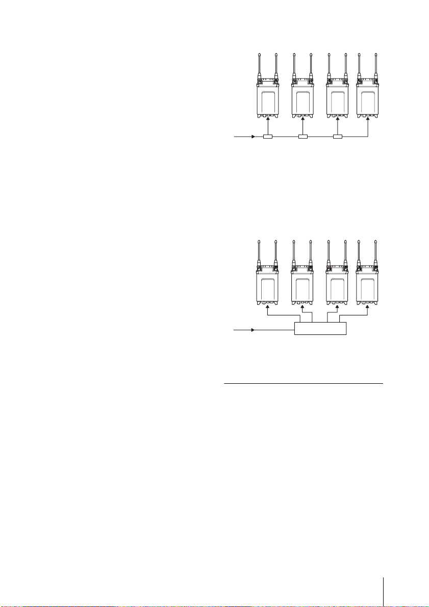
There are two types of systems for
synchronization using the master word
clock signal.
System example 1
The master word clock signal is split using
the T-shaped BNC splitter.
One of the devices including the DWRS01D must be terminated.
For details on h ow to terminate the word sync si gnal
on the DWR-S01D, refer to the Operating
Instructions supplied with the DWR-S01D.
a) a) a) b)
c)
a) 75-ohm termination setting: OFF
b) 75-ohm termination setting: ON
c) Master word clock signal
System example 2
The master word clock signal is supplied to
each device using the distributor. All the
devices must be terminated.
a) a) a) a)
b)
a) 75-ohm termination setting: ON
b) Master word clock signal
c) Word sync signal distributor
c)
Combining two DWA-01D
adapters
Two DWA-01D adapters, each of which a
DWR-S01D is attached, can be combined
to make a four-channel wireless receiver.
1 Remove four screws from the V-
shaped mount bracket and detach the
bracket.
Keep the removed screws in the screw
holes on the bracket for storage.
Attachment and connections
23
Page 24
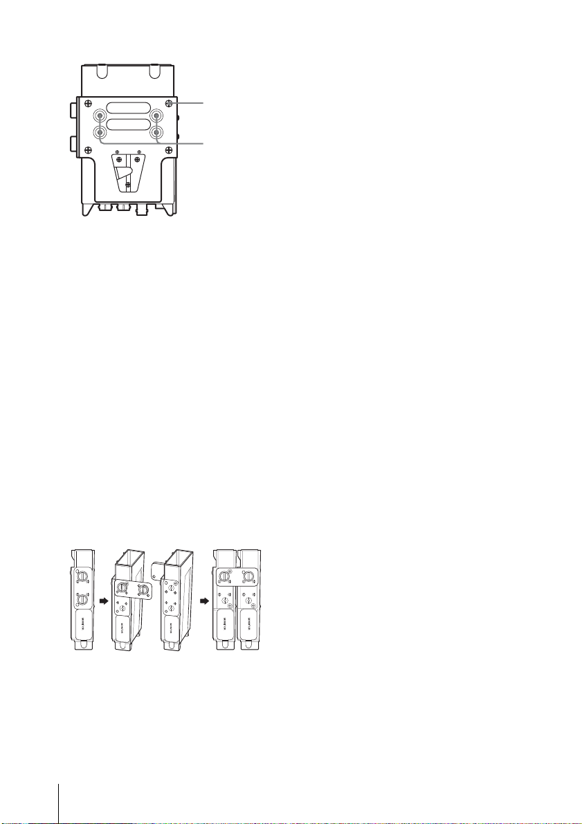
Screw
Screw
holes for
storage
2 Loosen the screws on the joint bracket
to remove it from the adapter.
3 Turn the joint bracket 90 degrees and
reattach the bracket to the adapter by
engaging two holes near the left screw
of the bracket with two projections at
the side of the adapter.
4 Do step 1 to 3 on the other adapter.
5 Place the adapters so that they show
the same side to you. Then, engage the
two holes near the right screw of the
bracket with two projections at the side
of the other adapter. Do the same on
the other side, using the bracket on the
other adapter. And then, fasten the
screws on the brackets to secure the
two adapters with each other.
Attachment and connections
24
Page 25
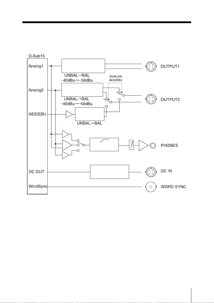
Block diagram
Step-down
transformer
Step-down
transformer
Transformer
Limiter
Volume
DC/DC
converter
Block diagram
25
Page 26

Troubleshooting
If you encounter a problem using this adapter, use the following checklist to find a solution.
For any problems with the transmitter or receiver, refer to the operating instructions of the
respective device. If the problem persists, consult your Sony dealer.
Symptom Meanings Remedy
The DWR-S01D or
the WRR-855 does
not turn on.
There is noise in the
analog signal output
from the OUTPUT2
connector when the
adapter is connected
to the device that
accepts the analog
signal only.
No signal is output
from the OUTPUT2
connector when the
adapter is connected
to the device that
accepts the analog
signal only.
No signal is output
from the OUTPUT2
connector when the
adapter is connected
to the device that
accepts the digital
signal.
The DWR-S01D or the
WRR-855 is not correctly
inserted into the slot of the
camcorder or this adapter.
The ANALOG AES/EBU
selector is set to AES/
EBU.
The tuner 2 of the DWRS01D is not turned on.
The WRR-855 is attached
to the adapter.
The ANALOG AES/EBU
selector is set to
ANALOG.
Insert the DWR-S01D or the WRR855 until it is firmly and completely
in, and then secure it with the
mounting screws.
Set the ANALOG AES/EBU
selector to ANALOG.
Turn on the tuner 2 of the DWRS01D.
The WRR-855 is a single-channel
receiver. Thus, there is no signal
output from the OUTPUT2
connector.
Set the ANALOG AES/EBU
selector to AES/EBU.
26
Troubleshooting
Page 27

Symptom Meanings Remedy
There is noise in the
audio output from
the digital device that
is connected to the
adapter.
There is no audio
output to the
PHONES connector.
When the monitor
output selector is set
to 1, audio from the
tuner 2 is mixed with
the audio from the
tuner 1.
The DWR-S01D inserted
in the adapter and the
digital device that is
connected to the adapter
are not in synchronization.
The WORD SYNC
connector is not 75-ohm
terminated.
The monitor level control
is turned down.
The tuner that is currently
turned off is selected by
the monitor output
selector.
The monitor output
selector is set to 2 when
the WRR-855 is attached
to the adapter.
“RX1+2” is selected on the
ANALOG OUTPUT1
function of the DWRS01D.
If the connected device is not
compatible with the asynchronous
input (i.e., the sampling rate
converter is not equipped), use the
word clock signal to synchronize
the device.
When the DWR-S01D that is
inserted in the adapter is the end
device or when the master word
clock signal is input to this adapter
only, add the 75-ohm termination to
the WORD SYNC connector by
using the UTILITY menu of the
DWR-S01D.
Adjust the monitor level by using
the monitor level control of the
adapter.
Check the POWER switch for the
corresponding tuner of the DWRS01D.
The WRR-855 is a single-channel
receiver. Thus, no audio is output
when the monitor output selector is
set to 2.
On the DWR-S01D, select “RX1”
on the ANALOG OUTPU1 function
of the UTILITY menu.
When “RX1+2” is selected, audio
from the tuner 1 and 2 are mixed
regardless of the monitor output
selection.
Troubleshooting
27
Page 28

Important notes
on operation
Notes on using the adapter
• The Digital Wireless Microphone
System product must be used within a
temperature range of 0°C to 50°C (32°F
to 122°F).
• Operating the adapter near electrical
equipment (motors, transformers, or
dimmers) may cause it to be affected by
electromagnetic induction. Keep the
adapter as far from such equipment as
possible.
On cleaning
• If the adapter is used in a very humid or
dusty place or in a place subject to an
active gas, clean its surface as well as the
connectors with a dry, soft cloth soon
after use. Lengthy use of the adapter in
such places or not cleaning it after its use
in such places may shorten its life.
• Clean the surface and the connectors of
the adapter with a dry, soft cloth. Never
use thinner, benzene, alcohol or any other
chemicals, since these may mar the
finish.
Specifications
Audio section
Audio output connector
SMC9-4S (female) (OUTPUT1/
OUTPUT2)
Analog output impedance
150 ohms or less
AES/EBU output impedance
110 ohms
WORD SYNC input
BNC-R, 75 ohms (when the DWR-
S01D is attached to the adapter
and 75-ohm termination is
added)
Monitor output
φ 3.5 mm TRS jack
Monitor output level
50 mW (16-ohm load, at T.H.D =
1%)
General
Power requirements
12 V DC
Operating voltage
10 V DC to 17 V DC
Operating temperature
0°C to +50°C (+32°F to +122°F)
Storage temperature
–20°C to +60°C (–4°F to +140°F)
To prevent electromagnetic
interference from portable
communication devices
The use of portable telephones and other
communication devices near the DWA01D may result in malfunction and
interference with audio signals. It is
recommended that portable
communication devices near the DWA01D be turned off.
Important notes on operation / Specifications
28
Page 29

Dimensions (unit: mm (inches))
Mass Approx. 330 g (11.6 oz)
Supplied accessories
DC power cable (1)
Mount plate (1)
Audio cable (2)
Operating Instructions (1)
Warranty booklet (1)
Design and specifications are subject to
change without notice.
Note
Always verify that the unit is operating
properly before use. SONY WILL NOT
BE LIABLE FOR DAMAGES OF ANY
KIND INCLUDING, BUT NOT
LIMITED TO, COMPENSATION OR
REIMBURSEMENT ON ACCOUNT OF
THE LOSS OF PRESENT OR
PROSPECTIVE PROFITS DUE TO
FAILURE OF THIS UNIT, EITHER
DURING THE WARRANTY PERIOD
OR AFTER EXPIRATION OF THE
WARRANTY, OR FOR ANY OTHER
REASON WHATSOEVER.
Specifications
29
Page 30

Français
AVERTISSEMENT
Une pression acoustique excessive en
provenance des écouteurs ou du casque peut
provoquer une baisse de l’acuité auditive.
Pour utiliser ce produit en toute sécurité,
évitez l’écoute prolongée à des pressions
sonores excessives.
Pour les utilisateurs au Canada
L’utilisation doit répondre aux deux
conditions suivantes : (1) ce matériel ne doit
pas provoquer de brouillage et (2) il doit
accepter tout brouillage, même celui qui est
susceptible d’affecter son fonctionnement.
Pour les clients en Europe
Ce produit portant la marque CE est
conforme à la Directive sur la compatibilité
électromagnétique (EMC) émise par la
Commission de la Communauté
européenne.
La conformité à cette directive implique la
conformité à la norme européenne suivante :
• EN301489-1/9/17:
Questions de compatibilité
électromagnétique et de spectre
radioélectrique (ERM)
Compatibilité électromagnétique (EMC)
Ce produit est prévu pour être utilisé dans
les environnements électromagnétiques
suivants : E1 (résidentiel), E2 (commercial
et industrie légère), E3 (urbain extérieur) et
E4 (environnement EMC contrôlé, ex.
studio de télévision).
Le fabricant de ce produit est Sony
Corporation, 1-7-1 Konan, Minato-ku,
Tokyo, Japon.
Le représentant autorisé pour EMC et la
sécurité des produits est Sony Deutschland
GmbH, Hedelfinger Strasse 61, 70327
Stuttgart, Allemagne. Pour toute question
concernant le service ou la garantie,
veuillez consulter les adresses indiquées
dans les documents de service ou de
garantie séparés.
30
Page 31

Table des matières
Caractéristiques ...................................................................32
Identification des parties .....................................................32
Avant/arrière/côté ..........................................................32
Dessous ..........................................................................33
Fixation et raccordements ...................................................35
Fixation de récepteur/du tuner .......................................35
Fixation/retrait du caméscope ........................................35
Combinaison de deux adaptateurs DWA-01D ..............36
Schéma fonctionnel.............................................................. 38
Dépannage ............................................................................ 39
Remarques importantes sur le fonctionnement ................41
Remarques sur l’utilisation de l’adaptateur ...................41
A propos du nettoyage ...................................................41
Spécifications ........................................................................42
FR
Table des matières
31
Page 32

Caractéristiques
Identification des
L’adaptateur sans fil DWA-01D permet au
récepteur numérique sans fil optionnel
DWR-S01D ou au tuner synthétisé UHF
WRR-855 d’être monté à l’arrière des
caméscopes Sony. Combiné au DWRS01D ou au WRR-855, le DWA-01D peut
aussi fonctionner comme récepteur sans fil
portable.
Grand choix de sorties audio
Pour atteindre une performance optimale, le
DWA-01D est équipé d’une grande variété
d’interfaces. L’un des connecteurs de sortie
audio analogique peut être réglé de façon à
émettre un signal au format numérique
AES/EBU. Un connecteur d’entrée word
sync est fourni à des fins d’utilisation
diverses.
Sortie de contrôle
L’unité est équipée d’un connecteur de
sortie de contrôle afin de permettre un
contrôle facile de la sortie audio.
Mécanisme unique
d’assemblage
Le DWA-01D est équipé d’un support
d’assemblage permettant aux deux
adaptateurs DWA-01D d’être facilement
combinés. Cela est particulièrement
pratique lorsque deux paires composées du
DWR-S01D et du DWA-01D sont utilisées
simultanément en tant que système de
réception à quatre canaux.
parties
Avant/arrière/côté
Structure imperméable
En montant correctement le DWR-S01D ou
le WRR-855 au DWA-01D, vous obtenez
une structure imperméable.
Caractéristiques / Identification des parties
32
Page 33

a Logement du récepteur sans fil
Insérez ici le DWR-S01D ou le WRR-855
optionnel.
Pour en savoir plus sur la fixation du récepteur ou
du tuner sur le DWA-01D, consultez « Fixation de
récepteur/du tuner » à la page 35.
b Orifices pour vis du récepteur sans
fil
Faites-y passer les vis de montage pour bien
fixer le récepteur/le tuner.
c Sélecteur de sortie de contrôle
Sélectionne la sortie audio du connecteur
PHONES.
1: émet l’audio du connecteur OUTPUT1
vers les canaux L/R (de gauche et de
droite).
1+2 : l’audio du connecteur OUTPUT1 est
mélangé à l’audio du connecteur
OUTPUT2 (uniquement lorsque le
connecteur OUTPUT2 est réglé pour
émettre un signal analogique) et émis vers
canaux L/R.
2: émet l’audio du connecteur OUTPUT2
(uniquement lorsque le connecteur
OUTPUT2 est réglé pour émettre un signal
analogique) vers les canaux L/R. Lorsque le
WRR-855 est fixé, il n’y a aucune sortie
audio du connecteur PHONES.
Remarque
La sortie de contrôle est répartie de la sortie
de signal analogique aux connecteurs
OUTPUT1/2. Lorsque l’audio émis par le
connecteur OUTPUT1 est modifié sur le
DWR-S01D à l’aide de la fonction
ANALOG OUTPUT1, la sortie moniteur
change en conséquence.
d Connecteur PHONES (sortie de
contrôle) (3,5 mm, prise TRS,
pointe : L, anneau : R, corps :
masse)
Raccordez ici le casque. Sélectionnez le
signal de sortie à l’aide du sélecteur de
sortie de contrôle.
e Commande du niveau de contrôle
Ajuste le niveau de sortie de contrôle
f Cache de la section de contrôle audio
Il s’agit du cache de la prise et des
commandes de la section de contrôle audio.
Lorsque vous n’utilisez pas le casque,
fermez ce cache.
g Support d’assemblage
Permet de combiner deux adaptateurs
DWA-01D.
Pour en savoir plus sur la façon de combiner deux
adaptateurs DWA-01D, consult ez « Combinaison de
deux adaptateurs DWA-01D » à la page 36.
h Support de montage en V
Il s’agit d’un support utilisé pour la fixation
au caméscope.
Dessous
a Connecteur DC IN (entrée
d’alimentation externe) (4 broches)
Raccordez-le au connecteur de sortie
d’alimentation externe du caméscope à
l’aide du câble d’alimentation CC fourni.
Ce connecteur prend en charge une tension
d’alimentation comprise entre 10 V CC et
17 V CC.
b Connecteur WORD SYNC (entrée
word sync) (type BNC)
Prend en charge un signal de
synchronisation externe.
Identification des parties
33
Page 34

Lorsque le DWR-S01D est fixé et que le
signal de synchronisation est reçu, le
fonctionnement du DWR-S01D peut être
synchronisé avec l’ensemble du système
audio. Afin que le fonctionnement du
DWR-S01D puisse être synchronisé,
sélectionnez « AUTO » ou
« EXTERNAL » dans l’élément SYNC
SOURCE du menu UTILITY du DWRS01D.
Notez que ce connecteur ne fonctionne pas
lorsque le WRR-855 est fixé.
Pour en savoir plus sur la fréquence du signal de
synchronisation, consultez le mode d’emploi fourni
avec le DWR-S01D.
Remarque
Même lorsque la terminaison 75 ohms a été
ajoutée sur le DWR-S01D, ce connecteur
fonctionne toujours comme le connecteur
d’entrée d’impédance élevée quand le
DWR-S01D est hors tension.
c Connecteur OUTPUT1 (sortie audio
analogique) (4 broches)
Emet un signal audio analogique équilibré.
Lorsque le DWR-S01D est fixé, l’audio du
tuner 1 ou 2 peut être sélectionné dans le
menu UTILITY du DWR-S01D. La sortie
de ce connecteur est réglée par défaut sur
l’audio du tuner 1.
Lorsque le WRR-855 est fixé, l’audio est
émis par ce connecteur uniquement.
Lorsque ce sélecteur est réglé sur
ANALOG, l’audio du tuner 2 est émis.
Notez que ce connecteur ne fonctionne pas
lorsque le WRR-855 est fixé.
e Sélecteur ANALOG AES/EBU
Lorsque le DWR-S01D est fixé, ce
sélecteur détermine le signal émis par le
connecteur OUTPUT2.
ANALOG : un signal audio analogique
équilibré est émis.
AES/EBU : un signal audio numérique au
format AES3 est émis.
Notez que ce sélecteur ne fonctionne pas
lorsque le WRR-855 est fixé.
d Connecteur OUTPUT2 (sortie audio
analogique/numérique) (4 broches)
Lorsque le DWR-S01D est fixé, ce
connecteur émet un signal audio analogique
équilibré ou un signal audio numérique au
format AES3.
Le signal de sortie peut être sélectionné à
l’aide du sélecteur ANALOG AES/EBU.
Identification des parties
34
Page 35

Fixation et
raccordements
Remarque
Si l’une des vis n’est pas assez serrée, la
structure ne sera pas imperméable ou
fonctionnera mal en raison des vibrations
qui peuvent se produire.
Fixation de récepteur/du
tuner
Insérez le DWR-S01D ou le WRR-855 dans
le logement du récepteur sans fil.
1 Insérez le récepteur/tuner dans le
logement du récepteur sans fil après
avoir vérifié le sens du connecteur Dsub 15 broches à l’intérieur du
logement et celui du récepteur/tuner.
Fixation/retrait du
caméscope
Utilisez le DWA-01D pour monter le
récepteur sans fil à l’arrière du caméscope
Sony. Pour cela, vous avez besoin d’un
support de montage optionnel (A-8278057-B) et de la plaque de fixation fournie
avec le DWA-01D. Pour retirer le DWA01D de la plaque de fixation, poussez le
levier de déverrouillage situé sur la plaque
de fixation.
Pack batterie BPGL95/GL65/L80S/
L60S (non fourni)
Support de montage
(A-8278-057-B) (non fourni)
Plaque de fixation
(fournie)
Tournevis cruciforme
2 Serrez les quatre vis de montage du
récepteur/tuner à l’aide d’un tournevis.
Pour raccorder le câble
d’alimentation
A l’aide du câble d’alimentation CC fourni
avec le DWA-01D, raccordez le connecteur
DC IN au connecteur DC OUT du
caméscope.
Fixation et raccordements
35
Page 36

Pour raccorder les câbles
audio
Pour le caméscope qui prend en
charge l’audio analogique
uniquement
Utilisez les câbles audio fournis avec le
DWA-01D pour raccorder les connecteurs
OUTPUT1 et 2 aux connecteurs AUDIO IN
du caméscope.
Pour le caméscope qui prend en
charge l’audio numérique
Réglez le sélecteur ANALOG AES/EBU
sur AES/EBU et raccordez le connecteur
OUTPUT2 au connecteur AUDIO IN du
caméscope à l’aide d’un câble audio fourni
avec le DWA-01D. Veillez à régler le
caméscope de façon à ce que le connecteur
AUDIO IN prenne en charge le signal audio
numérique AES/EBU.
A propos du raccordement du
signal de synchronisation
word clock et du signal audio
numérique
Le DWR-S01D fixé au DWA-01D et le
dispositif raccordé au DWA-01D via
l’interface audio numérique peuvent
fonctionner correctement si l’une des
conditions suivantes est remplie :
• Le dispositif raccordé au connecteur
OUTPUT2 du DWA-01D est équipé
d’un convertisseur de taux
d’échantillonnage.
• Le DWR-S01D est synchronisé avec le
dispositif raccordé au DWA-01D grâce à
l’entrée de signal word clock maître dans
le connecteur WORD SYNC du DWA01D.
Il existe deux types de systèmes de
synchronisation utilisant le signal word
clock maître.
Exemple de système 1
Le signal word clock maître est réparti à
l’aide du répartiteur BNC en T.
L’un des dispositifs contenant le DWRS01D doit avoir une terminaison.
Pour en savoir plus sur la terminaison du signal
word sync sur le DWR-S01D, consultez le mode
d’emploi fourni avec le DWR-S01D.
a) a) a) b)
c)
a) Réglage de la terminaison 75 ohms : OFF
b) Réglage de la terminaison 75 ohms : ON
c) Signal word clock maître
Exemple de système 2
Le signal word clock maître est envoyé à
chacun des dispositifs utilisant le
distributeur. Tous les dispositifs doivent
avoir une terminaison.
a) a) a) a)
b)
a) Réglage de la terminaison 75 ohms : ON
b) Signal word clock maître
c) Distributeur de signal word sync
c)
Combinaison de deux
adaptateurs DWA-01D
Deux adaptateurs DWA-01D, avec un
DWR-S01D fixé à chacun des deux,
peuvent être combinés afin d’obtenir un
récepteur sans fil à quatre canaux.
Fixation et raccordements
36
Page 37

1 Retirez les quatre vis du support de
montage en V et retirez le support.
Placez les vis que vous venez de retirer
dans les orifices du support destinés à
ranger les vis.
Vis
Orifices pour
ranger les vis
2 Desserrez les vis du support
d’assemblage afin de le retirer de
l’adaptateur.
3 Faites pivoter le support d’assemblage
à 90 degrés et fixez à nouveau le
support à l’adaptateur en plaçant les
deux orifices situés près de la vis de
gauche du support sur les deux parties
saillantes situées sur le côté de
l’adaptateur.
4 Effectuez les étapes 1 à 3 pour l’autre
adaptateur.
5 Placez les adaptateurs de façon à ce
que le même côté soit face à vous pour
les deux. Ensuite, placez les deux
orifices situés près de la vis de droite
du support sur les deux parties
saillantes situées sur le côté de l’autre
adaptateur. Suivez la même procédure
de l’autre côté en utilisant le support
sur l’autre adaptateur. Ensuite, serrez
les vis sur les supports afin de bien
fixer les deux adaptateurs l’un à
l’autre.
Fixation et raccordements
37
Page 38

Schéma fonctionnel
Transformateur
abaisseur
Transformateur
abaisseur
Transformateur
Limiteur
Convertisseur
CC/CC
Volume
Schéma fonctionnel
38
Page 39

Dépannage
Si vous rencontrez un problème lors de l’utilisation de cet adaptateur, utilisez la liste de
contrôle suivante pour trouver une solution. Pour tout problème lié à l’émetteur ou au
récepteur, consultez le mode d’emploi fourni avec le dispositif concerné. Si le problème
persiste, consultez votre revendeur Sony.
Symptôme Signification Solution
Le DWR-S01D ou le
WRR-855 ne
s’allume pas.
Il y a du bruit dans le
signal analogique
émis par le
connecteur
OUTPUT2 lorsque
l’adaptateur est
raccordé au
dispositif prenant en
charge les signaux
analogiques
uniquement.
Aucun signal n’est
émis par le
connecteur
OUTPUT2 lorsque
l’adaptateur est
raccordé au
dispositif prenant en
charge les signaux
analogiques
uniquement.
Aucun signal n’est
émis par le
connecteur
OUTPUT2 lorsque
l’adaptateur est
raccordé au
dispositif prenant en
charge les signaux
numériques.
Le DWR-S01D ou le
WRR-855 n’est pas
correctement inséré dans
le logement du
caméscope ou dans cet
adaptateur.
Le sélecteur ANALOG
AES/EBU est réglé sur
AES/EBU.
Le tuner 2 du DWR-S01D
n’est pas allumé.
Le WRR-855 est fixé à
l’adaptateur.
Le sélecteur ANALOG
AES/EBU est réglé sur
ANALOG.
Insérez le DWR-S01D ou le WRR855 jusqu’à ce qu’il soit fermement
et complètement à l’intérieur puis
serrez les vis de montage pour bien
le fixer.
Réglez le sélecteur ANALOG AES/
EBU sur ANALOG.
Allumez le tuner 2 du DWR-S01D.
Le WRR-855 est un récepteur à un
seul canal. Par conséquent, aucun
signal n’est émis par le connecteur
OUTPUT2.
Réglez le sélecteur ANALOG AES/
EBU sur AES/EBU.
Dépannage
39
Page 40

Symptôme Signification Solution
Il y a du bruit dans la
sortie audio du
dispositif numérique
raccordé à
l’adaptateur.
Il n’y a aucune sortie
audio du connecteur
PHONES.
Lorsque le sélecteur
de sortie de contrôle
est réglé sur 1,
l’audio du tuner 2 est
mélangé à l’audio du
tuner 1.
Le DWR-S01D inséré
dans l’adaptateur et le
dispositif numérique
raccordé à l’adaptateur ne
sont pas synchronisés.
Le connecteur WORD
SYNC n’a pas de
terminaison 75 ohms.
La commande du niveau
de contrôle est abaissée.
Le tuner actuellement
éteint a été sélectionné
par le sélecteur de sortie
de contrôle.
Le sélecteur de sortie de
contrôle est réglé sur 2
alors que le WRR-855 est
fixé à l’adaptateur.
« RX1+2 » est sélectionné
dans la fonction ANALOG
OUTPUT1 du DWR-S01D.
Si le dispositif raccordé n’est pas
compatible avec l’entrée
asynchrone (c-à-d s’il n’est pas
équipé d’un convertisseur de taux
d’échantillonnage), utilisez le signal
word clock pour synchroniser le
dispositif.
Lorsque le DWR-S01D inséré dans
l’adaptateur est le dispositif
terminal ou lorsque le signal word
clock maître est reçu par cet
adaptateur uniquement, ajoutez la
terminaison 75 ohms au
connecteur WORD SYNC à l’aide
du menu UTILITY du DWR-S01D.
Ajustez le niveau de contrôle à
l’aide de la commande du niveau
de contrôle de l’adaptateur.
Vérifiez l’interrupteur POWER du
tuner correspondant du DWRS01D.
Le WRR-855 est un récepteur à un
seul canal. Par conséquent, il n’y a
aucune sortie audio lorsque le
sélecteur de sortie de contrôle est
réglé sur 2.
Sur le DWR-S01D, sélectionnez
« RX1 » dans la fonction ANALOG
OUTPU1 du menu UTILITY.
Lorsque « RX1+2 » est
sélectionné, l’audio du tuner 1 et du
tuner 2 sont mélangés
indépendamment de la sortie de
contrôle sélectionnée.
40
Dépannage
Page 41

Remarques
importantes sur le
fonctionnement
Remarques sur l’utilisation
de l’adaptateur
• L’élément du système de microphone
numérique sans fil doit être utilisé dans
une fourchette de températures de 0 °C à
50 °C.
• L’adaptateur peut être affecté par
l’induction électromagnétique en cas de
fonctionnement près d’un appareil
électrique (moteur, transformateur ou
gradateur). Maintenez-le aussi loin que
possible de tels appareils.
A propos du nettoyage
• Si l’adaptateur est utilisé dans un endroit
très humide, poussiéreux ou exposé à un
gaz actif, nettoyez sa surface ainsi que les
connecteurs à l’aide d’un chiffon doux et
sec immédiatement après utilisation.
Utiliser de façon prolongée l’adaptateur
dans de tels endroits ou ne pas le nettoyer
après l’utilisation dans de tels endroits
risque de diminuer sa durée de vie.
• Nettoyez la surface et les connecteurs de
l’adaptateur avec un chiffon doux et sec.
N’utilisez jamais de diluant, de benzène,
d’alcool ou tout autre produit chimique,
car ils pourraient altérer la finition.
Pour éviter les interférences
électromagnétiques de
dispositifs de communication
portables
L’emploi de téléphones portables et
d’autres dispositifs de communication
près du DWA-01D peut se traduire par des
dysfonctionnements et des interférences
avec les signaux audio. Il est recommandé
de couper ces dispositifs de
communication portables près du DWA01D.
Remarques importantes sur le fonctionnement
41
Page 42

Spécifications
Section audio
Connecteur de sortie audio
SMC9-4S (femelle) (OUTPUT1/
OUTPUT2)
Impédance de sortie analogique
150 ohms ou moins
Impédance de sortie AES/EBU
110 ohms
Entrée WORD SYNC
BNC-R, 75 ohms (lorsque le DWR-
S01D est fixé à l’adaptateur et
la terminaison 75 ohms est
ajoutée)
Sortie de contrôle
Prise TRS φ 3,5 mm
Niveau de sortie de contrôle
50 mW (charge 16 ohms, avec
T.H.D = 1 %)
Généralités
Alimentation
12 V CC
Tension de fonctionnement
10 V CC à 17 V CC
Température de fonctionnement
0 °C à +50 °C (+32°F à +122°F)
Température de stockage
–20 °C à +60 °C (–4°F à +140°F)
Dimensions (Unité: mm (pouces))
Poids Env. 330 g (11,6 once)
Accessoires fournis
Câble d’alimentation CC (1)
Plaque de fixation (1)
Câble audio (2)
Mode d’emploi (1)
Brochure de garantie (1)
La conception et les spécifications sont
sujettes à modification sans préavis.
Remarque
Vérifiez toujours que l’appareil
fonctionne correctement avant
l’utilisation. Sony n’assumera pas de
responsabilité pour les dommages de
quelque sorte qu’ils soient, incluant
mais ne se limitant pas à la
compensation ou au remboursement, à
cause de la perte de profits actuels ou
futurs suite à la défaillance de cet
appareil, que ce soit pendant la période
de garantie ou après son expiration, ou
pour toute autre raison quelle qu’elle
soit.
42
Spécifications
Page 43

Deutsch
WARNUNG
Zu hoher Schalldruck von Ohrhörern und
Kopfhörern kann Gehörschäden
verursachen.
Um dieses Produkt sicher zu verwenden,
vermeiden Sie längeres Hören bei sehr
hohen Schalldruckpegeln.
Für Kunden in Europa
Dieses Produkt besitzt die CEKennzeichnung und erfüllt die EMVRichtlinie der EG-Kommission.
Die Erfüllung dieser Richtlinie beinhaltet
Übereinstimmung mit folgendem
europäischen Standard:
• EN301489-1/9/17:
Elektromagnetische Verträglichkeit und
Funkfrequenznangelegenheiten (ERM)
Elektromagnetische Verträglichkeit
(EMC)
Für die folgenden elektromagnetischen
Umgebungen: E1 (Wohnbereich), E2
(kommerzieller und in beschränktem Maße
industrieller Bereich), E3 (Stadtbereich im
Freien) und E4 (kontrollierter EMVBereich, z.B. Fernsehstudio).
Der Hersteller dieses Produkts ist Sony
Corporation, 1-7-1 Konan, Minato-ku,
Tokyo, Japan.
Der autorisierte Repräsentant für EMV und
Produktsicherheit ist Sony Deutschland
GmbH, Hedelfinger Strasse 61, 70327
Stuttgart, Deutschland. Bei jeglichen
Angelegenheiten in Bezug auf
Kundendienst oder Garantie wenden Sie
sich bitte an die in den separaten
Kundendienst- oder Garantiedokumenten
aufgeführten Anschriften.
DE
43
Page 44

Inhaltsverzeichnis
Eigenschaften .......................................................................45
Identifikation von Teilen .....................................................45
Vorderseite/Rückseite/Seite ...........................................45
Unterseite .......................................................................46
Montage und Anschlüsse .....................................................48
Anbringen der Empfänger-/Tunereinheit ......................48
Montage am/Demontage vom Camcorder .....................48
Anschluss von zwei DWA-01D Adaptern .....................50
Blockdiagramm.................................................................... 51
Fehlerbehebung.................................................................... 52
Wichtige Hinweise zum Betrieb .........................................54
Hinweise zur Verwendung des Adapters .......................54
Reinigung .......................................................................54
Technische Daten .................................................................55
44
Inhaltsverzeichnis
Page 45

Eigenschaften
Identifikation von
Durch den drahtlosen Adapter DWA-01D
ist es möglich, den optionalen digitalen
drahtlosen Empfänger DWR-S01D oder
den UHF-Synthesizer-Tuner WRR-855
rückseitig auf Sony Camcordern zu
montieren. In Kombination mit dem DWRS01D oder WRR-855 dient der DWA-01D
auch als tragbarer drahtloser Empfänger.
Große Auswahl an
Audioausgängen
Um seine Leistung vollständig nutzen zu
können, ist der DWA-01D mit einer großen
Reihe von Schnittstellen ausgerüstet. Einer
der analogen Audioausgangsanschlüsse
kann für die Ausgabe des
Digitalformatsignals AES/EBU
konfiguriert werden. Für verschiedene
Betriebsanforderungen steht ein Word
Sync-Eingangsanschluss zur Verfügung.
Monitorausgang
Zum einfachen Überprüfen der
Audioausgabe ist ein
Monitorausgangsanschluss vorhanden.
Teilen
Vorderseite/Rückseite/
Seite
Einzigartiger
Verbindungsmechanismus
Der DWA-01D ist mit einer
Verbindungshalterung ausgestattet, mit der
zwei DWA-01D Adapter einfach
kombiniert werden können. Das ist
besonders praktisch, wenn zwei Paare des
DWR-S01D und des DWA-01D
gleichzeitig als Vier-KanalEmpfängersystem verwendet werden.
Wetterfester Aufbau
Durch eine ordnungsgemäße Montage des
DWR-S01D oder des WRR-855 auf dem
DWA-01D wird ein wetterfester Aufbau
erzielt.
Eigenschaften / Identifikation von Teilen
45
Page 46

a Einschub für drahtlose Empfänger
Schieben Sie den optionalen DWR-S01D
oder WRR-855 hier ein.
Einzelheiten zur Montage des Empfängers oder
Tuners am DWA-01D finden Sie unter „Anbringen
der Empfänger-/Tunereinheit“ auf Seite 48.
b Schraublöcher für den drahtlosen
Empfänger
Ziehen Sie die Montageschrauben fest, um
die Empfänger-/Tunereinheit zu befestigen.
c Monitorausgangsschalter
Wählt den Audioausgang des Anschlusses
PHONES.
1: Audioausgabe des Anschlusses
OUTPUT1 über die L/R-Kanäle.
1+2: Die Audiosignale des Anschlusses
OUTPUT1 werden mit den Audiosignalen
des Anschlusses OUTPUT2 gemischt (nur,
wenn der Anschluss OUTPUT2 auf die
Ausgabe von analogen Signalen eingestellt
ist) und über die L/R-Kanäle ausgegeben.
2: Ausgabe der Audiosignale über den
Anschluss OUTPUT2 (nur, wenn der
Anschluss OUTPUT2 auf die Ausgabe von
analogen Signalen eingestellt ist) an die L/
R-Kanäle. Wenn der WRR-855
angeschlossen ist, werden über den
Anschluss PHONES keine Audiosignale
ausgegeben.
Hinweis
Die Monitorausgabe wird vom analogen
Signalausgang auf die Anschlüsse
OUTPUT1/2 verteilt. Wenn an den
Anschluss OUTPUT1 ausgegebene
Audiosignale mithilfe der Funktion
ANALOG OUTPUT1 auf dem DWRS01D geändert werden, ändert sich
dementsprechend auch die
Monitorausgabe.
d Anschluss PHONES
(Monitorausgang) (3,5 mm,
Klinkenbuchse, Spitze: L, Ring: R,
Hülse: Erde)
Schließen Sie hier die Kopfhörer an.
Wählen Sie das Ausgangssignal mithilfe
des Monitorausgangsschalters.
e Monitorpegelsteuerung
Zur Einstellung des
Monitorausgangspegels.
f Abdeckung für den
Audiomonitorbereich
Dies ist eine Abdeckung für die Buchse und
die Steuerungen des
Audiomonitorbereichs. Wenn Sie die
Kopfhörer nicht benutzen, schließen Sie
diese Abdeckung.
g Verbindungshalterung
Zum Anschließen von zwei Adaptern
DWA-01D.
Einzelheiten zum Anschluss von zwei Adaptern
DWA-01D finden Sie unter „Anschluss von zwei
DWA-01D Adaptern“ auf Seite 50.
h V-förmige Befestigungshalterung
Dies ist eine Befestigungshalterung für den
Camcorder.
Unterseite
a Buchse DC IN (externe
Stromversorgung) (4-polig)
Mithilfe des mitgelieferten
Gleichstromkabels an die externe
Stromsteckdose des Camcorders
anschließen. Dieser Anschluss akzeptiert
Stromspannungen zwischen 10 V und 17 V
Gleichspannung.
Identifikation von Teilen
46
Page 47

b Buchse WORD SYNC (Word-Sync-
Eingang) (BNC)
Akzeptiert externes Sync-Signal.
Wenn der DWR-S01D angeschlossen ist
und das Sync-Signal eingegeben wird, kann
der DWR-S01D synchronisiert mit dem
gesamten Audiosystem betrieben werden.
Um den DWR-S01D synchronisiert zu
betreiben, wählen Sie „AUTO“ oder
„EXTERNAL“ auf der SYNC SOURCEAnzeige im Menü UTILITY des DWRS01D.
Berücksichtigen Sie bitte, dass dieser
Anschluss nicht funktioniert, wenn der
WRR-855 angeschlossen ist.
Einzelheiten über die Frequenz des
Synchronisierungssignals finden Sie in der
Bedienungsanleitung des DWR-S01D.
Hinweis
Auch wenn die 75-Ohm-Klemme dem
DWR-S01D hinzugefügt wurde,
funktioniert dieser Anschluss immer noch
als hochohmiger Eingangs-Anschluss,
während der DWR-S01D ausgeschaltet ist.
c Anschluss OUTPUT1 (analoger
Audioausgang) (4-polig)
Für die Ausgabe symmetrischer analoger
Audiosignale.
Wenn der DWR-S01D angeschlossen ist,
können Audiosignale des Tuner 1 oder 2
gewählt werden, indem das Menü
UTILITY des DWR-S01D verwendet wird.
Die Ausgabe über diesen Anschluss ist
werkseitig auf die Audiosignale von Tuner
1 eingestellt.
Wenn der WRR-855 angeschlossen ist,
werden nur über diesen Anschluss
Audiosignale ausgegeben.
analoge Audiosignale oder digitale
Audiosignale im AES3-Format aus.
Die Ausgangssignale können mithilfe des
Schalters ANALOG AES/EBU gewählt
werden. Wenn dieser Schalter auf
ANALOG gestellt wird, werden die
Audiosignale von Tuner 2 ausgegeben.
Berücksichtigen Sie bitte, dass dieser
Anschluss nicht funktioniert, wenn der
WRR-855 angeschlossen ist.
e ANALOG AES/EBU-Schalter
Wenn der DWR-S01D angeschlossen ist,
bestimmt dieser Schalter die Signalausgabe
des Anschlusses OUTPUT2.
ANALOG: Es werden symmetrische
analoge Audiosignale ausgegeben.
AES/EBU: Es werden digitale
Audiosignale im AES3-Format
ausgegeben.
Berücksichtigen Sie bitte, dass dieser
Schalter nicht funktioniert, wenn der WRR855 angeschlossen ist.
d Anschluss OUTPUT2 (analoger/
digitaler Audioausgang) (4-polig)
Wenn der DWR-S01D angeschlossen ist,
gibt dieser Anschluss symmetrische
Identifikation von Teilen
47
Page 48

Montage und
Anschlüsse
Anbringen der Empfänger-/
Tunereinheit
Schieben Sie den DWR-S01D oder WRR855 in den Einschub für den drahtlosen
Empfänger.
1 Schieben Sie die Empfänger-/
Tunereinheit in den Einschub für den
drahtlosen Empfänger, nachdem Sie
die Ausrichtung des 15-poligen DSub-Anschlusses im Einschub und des
Anschlusses der Empfänger/
Tunereinheit überprüft haben.
2 Drehen Sie die vier
Befestigungsschrauben der
Empfänger-/Tunereinheit mit einem
Schraubenzieher fest.
Hinweis
Sollten eine oder mehrere Schrauben locker
sein, ist der Aufbau möglicherweise nicht
wetterbeständig oder es könnten Störungen
durch Vibrationen auftreten.
Montage am/Demontage
vom Camcorder
Zur Montage des drahtlosen Empfängers an
der Rückseite des Sony Camcorders
verwenden Sie den DWA-01D. Dafür sind
eine optionale Befestigungshalterung (A8278-057-B) und die mit dem DWA-01D
mitgelieferte Montageplatte erforderlich.
Um den DWA-01D von der Montageplatte
abzunehmen, drücken Sie auf den
Entnahmehebel auf der Montageplatte.
BP-GL95/GL65/L80S/
L60S Akku (nicht
mitgeliefert)
Montage und Anschlüsse
48
Befestigungshalterung (A8278-057-B) (nicht mitgeliefert)
Montageplatte
(mitgeliefert)
Kreuzschlitzschraubenzieher
Anschluss des Stromkabels
Mit dem Gleichstromkabel, das mit dem
DWA-01D mitgeliefert wird, verbinden Sie
den DC IN-Anschluss mit
dem DC OUT-Anschluss des Camcorders.
Page 49

Anschließen der Audiokabel
Für Camcorder, die nur analoge
Audiosignale akzeptieren
Verwenden Sie die mit dem DWA-01D
mitgelieferten Audiokabel, um die
Anschlüsse OUTPUT1 und 2 mit den
AUDIO IN-Anschlüssen des Camcorders
zu verbinden.
Für Camcorder, die nur digitale
Audiosignale akzeptieren
Stellen Sie den Schalter ANALOG AES/
EBU auf AES/EBU und verbinden Sie den
OUTPUT2-Anschluss mit dem AUDIO INAnschluss des Camcorders mithilfe des
Audiokabels, das mit dem DWA-01D
mitgeliefert wird. Achten Sie darauf, den
Camcorder so einzustellen, dass der
Anschluss AUDIO IN digitale AES/EBUAudiosignale akzeptiert.
Verbindung von WordclockSynchronisierungssignalen
und digitalen Audiosignalen
Der DWR-S01D, der an den DWA-01D
angeschlossen ist und das Gerät, das mit
dem DWA-01D über die digitale
Audioschnittstelle verbunden ist, können
unter einer der nachstehenden
Voraussetzungen auf exakte Weise
betrieben werden:
• Das Gerät, das an den Anschluss
OUTPUT2 des DWA-01D
angeschlossen ist, verfügt über einen
Abtastratenwandler.
• Der DWR-S01D ist mit dem Gerät
synchronisiert, das an den DWA-01D
angeschlossen ist, wobei der MasterWordclock-Signaleingang zum WORD
SYNC-Anschluss des DWA-01D
verwendet wird.
Beispiel System 1
Das Master-Wordclocksignal wird mit dem
T-förmigen BNC-Splitter verteilt.
Eines der Geräte einschließlich des DWRS01D muss angeschlossen werden.
Einzelheiten zum Anschließen des Wordsyncsignals
am DWR-S01D finden Sie in der
Bedienungsanleitung des DWR-S01D.
a) a) a) b)
c)
a) Einstellung 75-Ohm Anschluss: OFF
b) Einstellung 75-Ohm Anschluss: ON
c) Master-Wordclocksignal
Beispiel System 2
Das Master-Wordclocksignal wird an jedes
Gerät ausgegeben, das an den Verteiler
angeschlossen ist. Alle Geräte müssen
angeschlossen sein.
a) a) a) a)
b)
a) Einstellung 75-Ohm Anschluss: ON
b) Master-Wordclocksignal
c) Wordsyncsignal-Verteiler
c)
Es gibt zwei Arten von Systemen für die
Synchronisierung mithilfe des MasterWordclocksignals.
Montage und Anschlüsse
49
Page 50

Anschluss von zwei DWA01D Adaptern
Zwei DWA-01D Adapter, an die jeweils ein
DWR-S01D angeschlossen ist, können
kombiniert werden, sodass ein drahtloser
Empfänger mit vier Kanälen entsteht.
1 Entfernen Sie die vier Schrauben aus
der V-förmigen Halterung und nehmen
Sie die Halterung ab.
Lassen Sie die Schrauben zur
Aufbewahrung in den
Schraubenlöchern der Halterung.
Schraube
Schraubenlöcher zur
Lagerung
2 Lösen Sie die Schrauben der
Anschlusshalterung, damit Sie die
Halterung vom Adapter abnehmen
können.
an der Seite des anderen Adapters
einrasten. Das gleiche tun Sie auf der
anderen Seite, wobei Sie die Halterung
am anderen Adapter verwenden.
Danach ziehen Sie die Schrauben der
Halterungen fest, um die zwei Adapter
aneinander zu befestigen.
3 Drehen Sie die Anschlusshalterung um
90 Grad und befestigen Sie die
Halterung erneut am Adapter, indem
Sie die zwei Löcher in der Nähe der
linken Schraube an der Halterung und
die zwei Fortsätze an der Seite des
Adapters ineinander greifen lassen.
4 Führen Sie Schritt 1 bis 3 am anderen
Adapter aus.
5 Positionieren Sie die Adapter auf
solche Weise, dass die gleiche Seite in
Ihre Richtung weist. Dann lassen Sie
die zwei Löcher in der Nähe der
rechten Schraube in die zwei Fortsätze
Montage und Anschlüsse
50
Page 51

Blockdiagramm
Abwärtswandler
Abwärtswandler
Wandler
Limiter
Lautstärke
Gleichstrom/
Gleichstromwandler
Blockdiagramm
51
Page 52

Fehlerbehebung
Sollte ein Problem bei der Verwendung dieses Adapters auftreten, können Sie die folgende
Checkliste verwenden, um eine Lösung zu finden. Bei Problemen mit dem Sender oder
Empfänger nehmen Sie bitte die Bedienungsanleitung des jeweiligen Gerätes zu Hilfe. Wenn
das Problem bestehen bleibt, wenden Sie sich bitte an Ihren Sony-Händler.
Symptom Ursache Abhilfe
Der DWR-S01D
oder der WRR-855
kann nicht
eingeschaltet
werden.
Die analoge
Signalausgabe des
Anschlusses
OUTPUT2 rauscht,
wenn der Adapter an
das Gerät
angeschlossen ist,
das nur das analoge
Signal akzeptiert.
Es wird über den
Anschluss
OUTPUT2 kein
Signal ausgegeben,
wenn der Adapter an
das Gerät
angeschlossen ist,
das nur das analoge
Signal akzeptiert.
Es wird über den
Anschluss
OUTPUT2 kein
Signal ausgegeben,
wenn der Adapter an
das Gerät
angeschlossen ist,
welches das digitale
Signal akzeptiert.
Der DWR-S01D oder der
WRR-855 wurde nicht
richtig in den Einschub
des Camcorders oder
dieses Adapters
eingesetzt.
Der ANALOG AES/EBUSchalter ist auf AES/EBU
eingestellt.
Tuner 2 des DWR-S01D
ist nicht eingeschaltet.
Der WRR-855 ist an den
Adapter angeschlossen.
Der ANALOG AES/EBUSchalter ist auf ANALOG
eingestellt.
Schieben Sie den DWR-S01D oder
WRR-855 ein, bis er fest sitzt und
befestigen Sie ihn anschließend mit
den Befestigungsschrauben.
Stellen Sie den ANALOG AES/
EBU-Schalter auf ANALOG.
Schalten Sie Tuner 2 des DWRS01D ein.
Der WRR-855 ist ein 1-KanalEmpfänger. Das bedeutet, dass es
keine Signalausgabe über den
Anschluss OUTPUT2 gibt.
Stellen Sie den ANALOG AES/
EBU-Schalter auf AES/EBU.
52
Fehlerbehebung
Page 53

Symptom Ursache Abhilfe
Die Audioausgabe
über das an den
Adapter
angeschlossene
digitale Gerät
rauscht.
Es gibt keine
Audioausgabe an
den Anschluss
PHONES.
Wenn der
Monitorausgangssch
alter auf 1 eingestellt
ist, werden die
Audiosignale aus
Tuner 2 mit den
Audiosignalen aus
Tuner 1 gemischt.
Der in den Adapter
eingeschobene DWRS01D und das digitale
Gerät, das an den Adapter
angeschlossen ist, sind
nicht synchronisiert.
Der WORD SYNCAnschluss ist kein 75-Ohm
Anschluss.
Die
Monitorpegelsteuerung ist
herabgedreht.
Der momentan
ausgeschaltete Tuner wird
mithilfe des
Monitorausgangsschalters
selektiert.
Der
Monitorausgangsschalter
ist auf 2 eingestellt, wenn
der WRR-855 am Adapter
angeschlossen ist.
In der ANALOG
OUTPUT1-Funktion des
DWR-S01D ist „RX1+2“
gewählt.
Wenn das angeschlossene Gerät
nicht mit der asynchronen Eingabe
kompatibel ist (d. h. nicht mit einem
Abtastratenwandler ausgestattet
ist), verwenden Sie das
Wordclocksignal zum
Synchronisieren des Geräts.
Wenn der im Adapter
eingeschobene DWR-S01D das
Endgerät ist, oder wenn das
Master-Wordclocksignal nur an
diesen Adapter weitergegeben
wird, fügen Sie den 75-Ohm
Anschluss zum WORD SYNCAnschluss hinzu, indem Sie das
Menü UTILITY des DWR-S01D
benutzen.
Gleichen Sie den Monitorpegel mit
Hilfe der Monitorpegelsteuerung
des Adapters an.
Überprüfen Sie den POWERSchalter für den betreffenden Tuner
des DWR-S01D.
Der WRR-855 ist ein 1-KanalEmpfänger. Somit werden keine
Audiosignale ausgegeben, wenn
der Monitorausgangsschalter auf 2
eingestellt ist.
Wählen Sie am DWR-S01D „RX1“
in der Funktion ANALOG OUTPU1
im Menü UTILITY.
Wenn „RX1+2“ selektiert ist,
werden die Audiosignale aus Tuner
1 und 2 unabhängig von der Wahl
der Monitorausgabe gemischt.
Fehlerbehebung
53
Page 54

Wichtige
Hinweise zum
Betrieb
Hinweise zur Verwendung
des Adapters
• Das digitale drahtlose Mikrofonsystem
muss innerhalb eines
Temperaturbereichs von 0°C bis 50°C
verwendet werden.
• Bei Verwendung des Adapters in der
Nähe von Elektrogeräten (Motoren,
Transformatoren oder
Helligkeitsreglern) kann sich die
elektromagnetische Induktion auf diesen
auswirken. Halten Sie den Adapter so
weit wie möglich von derartigen Geräten
entfernt.
Reinigung
• Wenn der Adapter an einem sehr
feuchten oder staubigen Ort verwendet
wird oder Aktivgas ausgesetzt ist,
reinigen Sie seine Oberfläche und die
Anschlüsse nach Gebrauch mit einem
trockenen, weichen Tuch. Durch
längeren Gebrauch in solchen
Umgebungen oder wenn der Adapter
nach dem Einsatz in diesen Umgebungen
nicht gereinigt wird, kann seine
Lebensdauer beeinträchtigt werden.
• Reinigen Sie die Oberfläche und die
Anschlüsse des Adapters mit einem
trockenen, weichen Tuch. Benutzen Sie
niemals Verdünner, Benzol, Alkohol
oder andere Chemikalien, da diese die
Oberfläche beschädigen können.
Vermeidung von
elektromagnetischer Interferenz
von tragbaren
Kommunikationsgeräten
Der Einsatz von tragbaren Telefonen und
anderen Kommunikationsgeräten in der
Nähe des DWA-01D kann zu
Fehlfunktion und Interferenzen mit
Audiosignalen führen. Es wird
empfohlen, tragbare
Kommunikationsgeräte in der Nähe des
DWA-01D auszuschalten.
Wichtige Hinweise zum Betrieb
54
Page 55

Technische Daten
Audiobereich
Audioausgangsanschluss
SMC9-4S (weiblich) (OUTPUT1/
OUTPUT2)
Impedanz des analogen Ausgangs
150 Ohm oder weniger
AES/EBU-Ausgangsimpedanz
110 Ohm
WORD SYNC-Eingang
BNC-R, 75 Ohm (wenn der DWR-
S01D am Adapter
angeschlossen ist und ein 75Ohm Anschluss hinzugefügt
wurde)
Monitorausgang
φ 3,5 mm Klinkenbuchse
Monitorausgangspegel
50 mW (16-Ohm Lastwiderstand,
bei T.H.D = 1%)
Allgemeines
Leistungsanforderungen
12 V Gleichspannung
Betriebsspannung
10 V Gleichspannung bis 17 V
Gleichspannung
Betriebstemperatur
0°C bis +50°C
Lagertemperatur
–20°C bis +60°C
Abmessungen (Einheit: mm)
Gewicht
Ca. 330 g
Im Lieferumfang enthaltenes Zubehör
Gleichstromkabel (1)
Montageplatte (1)
Audiokabel (2)
Bedienungsanleitung (1)
Garantiebroschüre (1)
Konstruktive Änderungen, die dem
technischen Fortschritt dienen, bleiben
vorbehalten.
Hinweis
Bestätigen Sie vor dem Gebrauch immer,
dass das Gerät richtig arbeitet. SONY
KANN KEINE HAFTUNG FÜR
SCHÄDEN JEDER ART,
EINSCHLIESSLICH ABER NICHT
BEGRENZT AUF KOMPENSATION
ODER ERSTATTUNG, AUFGRUND
VON VERLUST VON AKTUELLEN
ODER ERWARTETEN PROFITEN
DURCH FEHLFUNKTION DIESES
GERÄTS ODER AUS JEGLICHEM
ANDEREN GRUND, ENTWEDER
WÄHREND DER GARANTIEFRIST
ODER NACH ABLAUF DER
GARANTIEFRIST, ÜBERNEHMEN.
Technische Daten
55
Page 56

Italiano
AVVERTENZA
Un’eccessiva pressione sonora da auricolari
e cuffie può causare la perdita dell’udito.
Per usare questo prodotto in maniera sicura,
evitare l’ascolto prolungato a livelli
eccessivi di pressione sonora.
Per i clienti in Europa
Questo prodotto recante il marchio CE è
conforme sia alla direttiva sulla
compatibilità elettromagnetica (EMC)
emesse dalla Commissione della
Comunità Europea.
La conformità a queste direttive implica la
conformità al seguente standard europeo:
• EN301489-1/9/17:
Questioni relative alla compatibilità
elettromagnetica e allo spettro delle
radiofrequenze (ERM)
Compatibilità elettromagnetica (CEM)
Questo prodotto è destinato all’uso nei
seguenti ambienti elettromagnetici: E1
(residenziali), E2 (commerciali e industriali
leggeri), E3 (esterni urbani) e E4 (ambienti
EMC controllati, ad esempio studi
televisivi).
Il fabbricante di questo prodotto è la Sony
Corporation, 1-7-1 Konan, Minato-ku,
Tokyo, Giappone.
La rappresentanza autorizzata per EMC e la
sicurezza dei prodotti è la Sony
Deutschland GmbH, Hedelfinger Strasse
61, 70327 Stoccarda, Germania. Per
qualsiasi questione riguardante l’assistenza
o la garanzia, si prega di rivolgersi agli
indirizzi riportati nei documenti
sull’assistenza o sulla garanzia a parte.
56
Page 57

Tabella dei contenuti
Caratteristiche ......................................................................58
Identificazione delle parti ....................................................58
Anteriore/posteriore/laterale ..........................................58
Parte inferiore ................................................................59
Montaggio e collegamenti ....................................................61
Montaggio del ricevitore/sintonizzatore ........................61
Montaggio/rimozione dal camcorder .............................61
Per combinare due adattatori DWA-01D ......................62
Diagramma a blocchi........................................................... 64
Risoluzione dei problemi..................................................... 65
Note importanti sul funzionamento ...................................67
Note sull’utilizzo dell’adattatore ...................................67
Pulizia ............................................................................67
Caratteristiche tecniche .......................................................68
Tabella dei contenuti
IT
57
Page 58

Caratteristiche
Identificazione
L’adattatore wireless DWA-01D consente
al ricevitore wireless digitale opzionale
DWR-S01D o al sintetizzatore a sintesi di
frequenza UHF WRR-855 il montaggio
posteriore sui camcorder Sony. Insieme al
DWR-S01D o WRR-855, il DWA-01D è in
grado di funzionare anche come ricevitore
wireless portatile.
Vasta gamma di uscite audio
Per sfruttare al meglio tutte le sue funzioni,
il DWA-01D è dotato di una vasta gamma
di interfacce. Uno dei connettori di uscita
audio analogico può essere impostato per
emettere il segnale digitale AES/EBU.
Viene fornito un connettore di ingresso
word sync per differenti necessità
operative.
Uscita monitor
Viene fornito un connettore di uscita
monitor per semplificare il monitoraggio
dell’uscita audio.
Meccanismo snodato
univoco
Il DWA-01D è dotato di una staffa snodata
che consente di combinare facilmente due
adattatori DWA-01D. Ciò è estremamente
pratico quando si usano allo stesso tempo
due coppie del DWR-S01D e del DWA01D come sistema di ricezione a quattro
canali.
delle parti
Anteriore/posteriore/
laterale
Struttura a prova di
intemperie
Montando correttamente il DWR-S01D o il
WRR-855 sul DWA-01D, si ottiene una
struttura a prova di intemperie.
Caratteristiche / Identificazione delle parti
58
Page 59

a Slot del ricevitore wireless
Inserire qui il DWR-S01D o il WRR-855
opzionale.
Per i dettagli sul montaggio del ricevitore o del
sintonizzatore sul DWA-01D, vedere “Montaggio
del ricevitore/sintonizzatore” a pagina 61.
b Fori per viti del ricevitore wireless
Inserire le viti per fissare il ricevitore/
sintonizzatore.
c Selettore di uscita monitor
Seleziona l’uscita dal connettore PHONES.
1: emette l’audio dal connettore OUTPUT1
sui canali L/R.
1+2: l’audio che fuoriesce dal connettore
OUTPUT1 si unisce a quello proveniente
dal connettore OUTPUT2 (solo se il
connettore OUTPUT2 è impostato sul
segnale analogico in uscita) e viene emesso
sui canali L/R.
2: emette l’audio dal connettore OUTPUT2
(solo se il connettore OUTPUT2 è
impostato sul segnale analogico in uscita)
sui canali L/R. Quando si collega il WRR855, non viene emesso alcun audio dal
connettore PHONES.
Nota
L’uscita monitor viene separata da quella
del segnale analogico sui connettori
OUTPUT1/2. Quando l’audio emesso sul
connettore OUTPUT1 viene cambiato sul
DWR-S01D tramite la funzione ANALOG
OUTPUT1, anche l’uscita monitor.
d Connettore PHONES (uscita
monitor) (3,5 mm, jack TRS, punta:
L, anello: R, manicotto: messa a
terra)
Collegare qui le cuffie. Selezionare il
segnale di uscita tramite il selettore di uscita
monitor.
e Controllo livello monitor
Regola il livello di uscita del monitor.
f Coperchio sezione monitor audio
È un coperchio per il jack e i comandi della
sezione monitor audio. Chiudere il
coperchio se non si usano le cuffie.
g Staffa snodata
Combina due adattatori DWA-01D.
Per i dettagli su come combinare due adattatori
DWA-01D, vedere “Per combinare due adattatori
DWA-01D” a pagina 62.
h Staffa a V
È una staffa adoperata per il collegamento
al camcorder.
Parte inferiore
a Connettore DC IN (ingresso di
alimentazione esterno) (a 4 pin)
Collegarlo all’uscita di alimentazione
esterna del camcorder tramite il cavo di
alimentazione CC in dotazione. Questo
connettore accetta una tensione di
alimentazione tra 10 V CC e 17 V CC.
b Connettore WORD SYNC (ingresso
word sync) (BNC)
Accetta un segnale di sincronizzazione
esterno.
Quando si collega il DWR-S01D e si
immette il segnale di sincronizzazione, il
DWR-S01D consente il funzionamento
sincrono con l’intero sistema audio. Per
ottenere il funzionamento sincrono del
DWR-S01D , selezionare “AUTO” o
Identificazione delle parti
59
Page 60

“EXTERNAL” sull’indicazione SYNC
SOURCE del menu UTILITY del DWRS01D.
Questo connettore non funziona quando il
WRR-855 è collegato.
Per i dettagli sulla frequenza del segnale di
sincronizzazione, consultare le istruzioni per l’uso
in dotazione con il DWR-S01D.
Nota
Nonostante sia stata aggiunta la
terminazione a 75 ohm sul DWR-S01D,
questo connettore funziona ancora come
connettore di ingresso ad impedenza
elevata mentre il DWR-S01D è spento.
c Connettore OUTPUT1 (uscita audio
analogica) (4 pin)
Emette segnale audio analogico bilanciato.
Quando si collega il DWR-S01D, è
possibile selezionare l’audio dai
sintonizzatori 1 o 2 tramite il menu
UTILITY del DWR-S01D. L’uscita da
questo connettore è preimpostata sull’audio
proveniente dal sintonizzatore 1.
Quando si collega il WRR-855, l’audio
viene emesso solo da questo connettore.
e Selettore ANALOG AES/EBU
Quando si collega il DWR-S01D, questo
selettore determina l’uscita di segnale dal
connettore OUTPUT2.
ANALOG: viene emesso il segnale audio
analogico bilanciato.
AES/EBU: viene emesso il segnale audio
digitale AES3.
Questo selettore non funziona quando il
WRR-855 è collegato.
d Connettore OUTPUT2 (uscita audio
analogica/digitale) (4 pin)
Quando si collega il DWR-S01D, questo
connettore emette segnale audio analogico
bilanciato o segnale audio digitale AES3.
È possibile selezionare il segnale di uscita
tramite il selettore ANALOG AES/EBU.
Quando questo selettore è impostato su
ANALOG, viene emesso l’audio dal
sintonizzatore 2.
Questo connettore non funziona quando il
WRR-855 è collegato.
Identificazione delle parti
60
Page 61

Montaggio e
collegamenti
Montaggio del ricevitore/
sintonizzatore
Inserire il DWR-S01D o il WRR-855 nello
slot del ricevitore wireless.
1 Inserire il ricevitore/sintonizzatore
nello slot del ricevitore wireless dopo
aver osservato la direzione del
connettore D-sub a 15 pin dentro lo
slot e quella del ricevitore/
sintonizzatore.
2 Serrare le quattro viti di fissaggio del
ricevitore/sintonizzatore con un
cacciavite.
Nota
Se una delle viti è allentata, non è possibile
ottenere una struttura a prova di intemperie
o potrebbero verificarsi problemi di
funzionamento dovuti a vibrazioni.
Montaggio/rimozione dal
camcorder
Usare il DWA-01D per montare il
ricevitore wireless sulla parte posteriore del
camcorder Sony. A tal fine, sono necessarie
una staffa opzionale (A-8278-057-B) e la
piastra di fissaggio in dotazione con il
DWA-01D. Per rimuovere il DWA-01D
dalla piastra di fissaggio, premere la leva
apposita sulla piastra.
Pacco batteria BP-GL95/
GL65/L80S/L60S (non in
dotazione)
Staffa (A-8278-057-B)
(non in dotazione)
Piastra di fissaggio
(in dotazione)
Cacciavite Phillips
Per collegare il cavo di
alimentazione
Con il cavo di alimentazione CC in
dotazione con il DWA-01D, collegare il
connettore DC IN al connettore DC OUT
del camcorder.
Montaggio e collegamenti
61
Page 62

Per collegare i cavi audio
Per i camcorder che accettano
solo audio analogico
Usare i cavi audio in dotazione con il
DWA-01D per collegare i connettori
OUTPUT1 e 2 ai connettori AUDIO IN del
camcorder.
Per i camcorder che accettano
audio digitale
Impostare il selettore ANALOG AES/EBU
su AES/EBU e collegare il connettore
OUTPUT2 al connettore AUDIO IN del
camcorder tramite un cavo audio in
dotazione con il DWA-01D. Assicurarsi di
impostare il camcorder in modo che il
connettore AUDIO IN accetti il segnale
audio digitale AES/EBU.
Collegamento del segnale di
sincronizzazione word clock e
del segnale audio digitale
Il DWR-S01D collegato al DWA-01D e il
dispositivo collegato al DWA-01D tramite
l’interfaccia audio digitale funzionano
correttamente solo alle seguenti condizioni:
• Il dispositivo collegato al connettore
OUTPUT2 del DWA-01D deve essere
dotato di convertitore velocità di
campionamento.
• Il DWR-S01D deve essere sincronizzato
con il dispositivo collegato al DWA-01D
tramite l’ingresso di segnale master word
clock sul connettore WORD SYNC del
DWA-01D.
Vi sono due tipi di sistemi di
sincronizzazione tramite il segnale master
word clock.
Esempio di sistema 1
Il segnale master word clock viene separato
con lo splitter BNC a T.
Uno dei dispositivi, compreso il DWRS01D, deve disporre di terminazione.
Per i dettagli su come effettuare la terminazione del
segnale word sync sul DWR-S01D, consultare le
istruzioni per l’uso in dotazione con il DWR-S01D.
a) a) a) b)
c)
a) Impostazione di terminazione a 75 ohm: OFF
b) Impostazione di terminazione a 75 ohm: ON
c) Segnale master word clock
Esempio di sistema 2
Il segnale master word clock viene fornito a
ciascun dispositivo che utilizza il
distributore. Tutti i dispositivi devono
disporre di terminazione.
a) a) a) a)
b)
a) Impostazione di terminazione a 75 ohm: ON
b) Segnale master word clock
c) Distributore di segnale word sync
c)
Per combinare due
adattatori DWA-01D
È possibile combinare due adattatori DWA01D a cui è collegato un DWR-S01D per
ottenere un ricevitore wireless a quattro
canali.
1 Rimuovere le quattro viti dalla staffa a
V e smontare la staffa.
Conservare le viti rimosse sui fori
appositi della staffa.
Montaggio e collegamenti
62
Page 63

Vite
Fori delle viti
per la
conservazione
2 Allentare le viti della staffa snodata per
rimuoverla dall’adattatore.
3 Ruotare la staffa snodata di 90 gradi e
rimontare la staffa sull’adattatore
facendo corrispondere i due fori in
prossimità della vite sinistra della
staffa con le due sporgenze sul lato
dell’adattatore.
4 Eseguire i punti da 1 a 3 sull’altro
adattatore.
5 Posizionare gli adattatori in modo che
lo stesso lato sia rivolto verso l’utente.
Quindi, far corrispondere i due fori in
prossimità della vite destra della staffa
con le due sporgenze sul lato dell’altro
adattatore. Effettuare la stessa
operazione sull’altro lato con la staffa
dell’altro adattatore. Quindi, serrare le
viti sulle staffe per fissare tra essi i due
adattatori.
Montaggio e collegamenti
63
Page 64

Diagramma a blocchi
Trasformatoreriduttore
Trasformatoreriduttore
Trasformatore
Limitatore
Convertitore
CC/CC
Volume
Diagramma a blocchi
64
Page 65

Risoluzione dei problemi
In caso di problemi durante l’uso del presente adattatore, adoperare la seguente lista di
verifica per trovare una soluzione. In caso di problemi con il trasmettitore o il ricevitore,
consultare le istruzioni per l’uso in dotazione con i rispettivi dispositivi. Se il problema
persiste, rivolgersi al proprio rivenditore Sony.
Problema Significato Soluzione
Non è possibile
accendere il DWRS01D o il WRR-855.
Quando l’adattatore
è collegato al
dispositivo che
accetta solo segnale
analogico, si
verificano
interferenze
nell’uscita di segnale
analogico
proveniente dal
connettore
OUTPUT2.
Quando l’adattatore
è collegato al
dispositivo che
accetta solo segnale
analogico, non viene
emesso alcun
segnale dal
connettore
OUTPUT2.
Quando l’adattatore
è collegato al
dispositivo che
accetta il segnale
digitale, non viene
emesso alcun
segnale dal
connettore
OUTPUT2.
Il DWR-S01D o il WRR855 non è inserito
correttamente nello slot
del camcorder o di questo
adattatore.
Il selettore ANALOG AES/
EBU è impostato su AES/
EBU.
Il sintonizzatore 2 del
DWR-S01D non è acceso.
Il WRR-855 è collegato
all’adattatore.
Il selettore ANALOG AES/
EBU è impostato su
ANALOG.
Inserire saldamente e
completamente il DWR-S01D o il
WRR-855 , quindi fissarlo con viti
adeguate.
Impostare il selettore ANALOG
AES/EBU su ANALOG.
Accendere il sintonizzatore 2 del
DWR-S01D.
Il WRR-855 è un ricevitore a canale
singolo. per cui non è presente
alcuna uscita di segnale dal
connettore OUTPUT2.
Impostare il selettore ANALOG
AES/EBU su AES/EBU.
Risoluzione dei problemi
65
Page 66

Problema Significato Soluzione
Vi sono interferenze
nell’uscita audio del
dispositivo digitale
collegato
all’adattatore.
Non vi è alcuna
uscita audio sul
connettore
PHONES.
Quando il selettore
di uscita monitor è
impostato su 1,
l’audio emesso dal
sintonizzatore 2 si
unisce a quello
proveniente dal
sintonizzatore 1.
Il DWR-S01D inserito
nell’adattatore e il
dispositivo digitale
collegato all’adattatore
non sono sincronizzati.
Il connettore WORD
SYNC non dispone di
sincronizzazione a 75
ohm.
Il controllo livello monitor è
abbassato.
Il sintonizzatore
attualmente spento viene
selezionato dal selettore di
uscita monitor.
Il selettore di uscita
monitor è impostato su 2
quando si collega WRR855 all’adattatore.
“RX1+2” viene selezionato
nella funzione ANALOG
OUTPUT1 del DWRS01D.
Se il dispositivo collegato non è
compatibile con ingresso asincrono
(ad esempio non dispone di
convertitore velocità di
campionamento), usare il segnale
word clock per sincronizzare il
dispositivo.
Quando il DWR-S01D inserito
nell’adattatore è il dispositivo finale
o il segnale master word clock
viene immesso solo sull’adattatore,
aggiungere la terminazione a 75
ohm sul connettore WORD SYNC
tramite il menu UTILITY del DWRS01D.
Regolare il livello del monitor
utilizzando il controllo livello
monitor dell’adattatore.
Controllare l’interruttore POWER
nel sintonizzatore corrispondente
del DWR-S01D.
Il WRR-855 è un ricevitore a canale
singolo. per cui non viene emesso
audio quando il selettore di uscita
monitor è impostato su 2.
Sul DWR-S01D, selezionare “RX1”
sulla funzione ANALOG OUTPU1
del menu UTILITY.
Quando si seleziona “RX1+2”,
l’audio emesso dai sintonizzatori 1
e 2 viene mischiato,
indipendentemente dalla selezione
di uscita monitor.
Risoluzione dei problemi
66
Page 67

Note importanti
sul
funzionamento
Note sull’utilizzo
dell’adattatore
• Il sistema di microfoni wireless digitali
deve essere usato a temperature
comprese nella gamma da 0°C a 50°C.
• L’uso dell’adattatore nei pressi di
apparecchiature elettriche (motori,
trasformatori o regolatori luminosi) può
sottoporre i prodotti ad induzione
elettromagnetica. Tenere l’adattatore il
più lontano possibile da tali
apparecchiature.
Pulizia
• Se l’adattatore viene usato in ambienti
estremamente umidi o polverosi oppure
soggetti a gas attivi, pulire la superficie e
i connettori con un panno morbido e
asciutto subito dopo l’uso. Un utilizzo
prolungato dell’adattatore in tali
ambienti oppure non eseguire la pulizia
dopo l’uso potrebbe ridurne la vita utile.
• Pulire la superficie e i connettori
dell’adattatore con un panno morbido e
asciutto. Non usare mai diluenti,
benzene, alcool o altre sostanze
chimiche, in quanto potrebbero
danneggiare la finitura.
Per evitare interferenze
elettromagnetiche da dispositivi
di comunicazione portatili
L’uso di telefoni portatili e altri dispositivi
di comunicazione nei pressi del DWA01D potrebbe causare problemi di
funzionamento e interferenze con i
segnali audio. Si consiglia di tenere spenti
i dispositivi di comunicazione portatili nei
pressi del DWA-01D.
Note importanti sul funzionamento
67
Page 68

Caratteristiche
tecniche
Sezione audio
Connettore di uscita audio
SMC9-4S (femmina) (OUTPUT1/
OUTPUT2)
Impedenza di uscita analogica
150 ohm o inferiore
Impedenza di uscita AES/EBU
110 ohm
Ingresso WORD SYNC
BNC-R, 75 ohm (quando il DWR-
S01D è collegato all’adattatore
e si aggiunge la terminazione a
75 ohm)
Uscita monitor
Jack TRS, φ 3,5 mm
Livello di uscita del monitor
50 mW (carico di 16 ohm, T.H.D =
1%)
Dimensioni (Unità: mm)
Peso Circa 330 g
Accessori in dotazione
Cavo di alimentazione CC (1)
Piastra di fissaggio (1)
Cavo audio (2)
Istruzioni per l’uso (1)
Libretto di garanzia (1)
Generale
Alimentazione
12 V CC
Tensione operativa
Da 10 V CC a 17 V CC
Temperatura di utilizzo
Da 0°C a +50°C
Temperatura di conservazione
Da –20°C a +60°C
Caratteristiche tecniche
68
Il design e le caratteristiche tecniche sono
soggetti a modifiche senza preavviso.
Nota
Verificare sempre che l’apparecchio stia
funzionando correttamente prima di
usarlo. LA SONY NON SARÀ
RESPONSABILE DI DANNI DI
QUALSIASI TIPO, COMPRESI, MA
SENZA LIMITAZIONE A,
RISARCIMENTI O RIMBORSI A
CAUSA DELLA PERDITA DI
PROFITTI ATTUALI O PREVISTI
DOVUTA A GUASTI DI QUESTO
APPARECCHIO, SIA DURANTE IL
PERIODO DI VALIDITÀ DELLA
GARANZIA SIA DOPO LA
SCADENZA DELLA GARANZIA, O
PER QUALUNQUE ALTRA
RAGIONE.
Page 69

Español
ADVERTENCIA
Una excesiva presión de sonido de los
auriculares y cascos auriculares puede
provocar una pérdida de percepción de sus
oídos.
Para utilizar este producto con seguridad,
no escuche durante mucho tiempo con
niveles de presión de sonido excesivos.
Para los clientes de Europa
Este producto con marcado CE cumple con
las directivas de compatibilidad
electromagnética de la Comisión Europea.
El cumplimiento de estas directivas implica
la conformidad con el siguiente estándar
europeo:
• EN301489-1/9/17:
Cuestiones de Compatibilidad
Electromagnética y Espectro
Radioeléctrico (ERM)
Compatibilidad electromagnética (EMC)
Este producto ha sido diseñado para
utilizarse en los entornos electromagnéticos
siguientes: E1 (zona residencial), E2 (zona
comercial e industrial ligera), E3
(exteriores urbanos), y E4 (entorno con
EMC controlada, p. ej., estudio de
televisión).
El fabricante de este producto es Sony
Corporation, con dirección en 1-7-1 Konan,
Minato-ku, Tokio, Japón.
El Representante autorizado para EMC y
seguridad del producto es Sony
Deutschland GmbH, Hedelfinger Strasse
61, 70327 Stuttgart, Alemania. Para asuntos
relacionados con el servicio y la garantía,
consulte las direcciones entregadas por
separado para los documentos de servicio o
garantía.
ES
69
Page 70

Índice
Características ......................................................................71
Identificación de las piezas ..................................................71
Parte frontal/posterior/lateral .........................................71
Parte inferior ..................................................................72
Acoplamiento y conexiones .................................................74
Acoplamiento del receptor/sintonizador ........................74
Acoplamiento/Desacoplamiento del camcorder ............74
Combinación de dos adaptadores DWA-01D ................75
Esquema funcional............................................................... 77
Solución de problemas......................................................... 78
Notas importantes sobre el funcionamiento ......................80
Notas sobre el uso del adaptador ...................................80
Acerca de la limpieza .....................................................80
Especificaciones ....................................................................81
70
Índice
Page 71

Características
Identificación de
El adaptador inalámbrico DWA-01D
permite instalar el receptor inalámbrico
digital DWR-S01D o el sintonizador
sintetizador UHF WRR-855 opcionales en
la parte posterior de los camcorders de
Sony. Si se combina con el DWR-S01D o el
WRR-855, el DWA-01D también puede
funcionar como receptor inalámbrico
portátil.
Varias salidas de audio
disponibles
Para ofrecer el máximo rendimiento, el
DWA-01D está equipado con una amplia
gama de interfaces. Uno de los conectores
de salida de audio analógico puede ajustarse
para emitir la señal de formato digital AES/
EBU. El conector de entrada word sync está
disponible para varias necesidades
operativas.
Salida de monitor
El conector de salida de monitor permite
controlar de forma sencilla la salida de
audio.
las piezas
Parte frontal/posterior/
lateral
Extraordinario mecanismo de
unión
El DWA-01D está equipado con un soporte
de unión que permite combinar fácilmente
dos adaptadores DWA-01D. Esto resulta
idóneo cuando se utilizan dos pares del
DWR-S01D y del DWA-01D al mismo
tiempo a modo de sistema receptor de
cuatro canales.
Estructura impermeable
Si el montaje del DWR-S01D o del WRR855 se realiza correctamente en el DWA01D, la estructura resultante será
impermeable.
Características / Identificación de las piezas
71
Page 72

a Ranura del receptor inalámbrico
Inserte aquí el DWR-S01D o el WRR-855
opcionales.
Para obtener información d etallada acerca de cómo
acoplar el receptor o el sintonizador al DWA-01D,
consulte "Acoplamiento del receptor/sintonizador"
en la página 74.
b Orificios para los tornillos del
receptor inalámbrico
Apriete los tornillos de montaje para
asegurar el receptor/sintonizador.
c Selector de salida de monitor
Selecciona la salida de audio desde el
conector PHONES.
1: Emite el audio desde el conector
OUTPUT1 a los canales L/R.
1+2: El audio del conector OUTPUT1 se
mezcla con el audio del conector
OUTPUT2 (sólo cuando se ajusta el
conector OUTPUT2 para emitir la señal
analógica) y se emite por los canales L/R.
2: Emite el audio del conector OUTPUT2
(sólo cuando se ajusta el conector
OUTPUT2 para emitir la señal analógica)
por los canales L/R. Cuando se acopla el
WRR-855, no se emite audio desde el
conector PHONES.
Nota
La salida de monitor se divide desde salida
de señal analógica a los conectores
OUTPUT1/2. Cuando el audio que se emite
al conector OUTPUT1 se cambia en el
DWR-S01D mediante la función
ANALOG OUTPUT1, la salida de monitor
cambia en consecuencia.
e Control del nivel del monitor
Ajuste el nivel de salida de monitor.
f Cubierta de la sección del monitor
de audio
Se trata de una cubierta para la toma y los
controles de la sección del monitor de
audio. Ciérrela cuando no utilice los
auriculares.
g Soporte de unión
Combina dos adaptadores DWA-01D.
Para obtener informació n detallada acerca de cómo
combinar dos adaptadores DWA-01D, consulte
"Combinación de dos adaptadores DWA-01D" en la
página 75.
h Soporte de montaje en V
Se trata de un soporte que se utiliza para
acoplar al camcorder.
Parte inferior
a Conector DC IN (entrada de
alimentación externa) (4 clavijas)
Conecte el conector de salida de
alimentación externa al camcorder
mediante el cable de alimentación CC
suministrado. Este conector admite un
voltaje de entre 10 y 17 V CC.
d Conector PHONES (salida de
monitor) (3,5 mm, toma TRS, punta:
L, anillo: R, manga: tierra)
Conecte aquí los auriculares. Seleccione la
señal de salida mediante el selector de
salida de monitor.
Identificación de las piezas
72
b Conector WORD SYNC (entrada
word sync) (tipo BNC)
Admite señal de sincronización externa.
Page 73

Cuando se acopla el DWR-S01D y entra la
señal de sincronización, el DWR-S01D
puede funcionar de forma sincronizada con
todo el sistema de audio. Para que el DWRS01D funcione de forma sincronizada,
seleccione “AUTO” o “EXTERNAL” en la
indicación SYNC SOURCE del menú
UTILITY del DWR-S01D.
Tenga en cuenta que este conector no
funciona cuando se acopla el WRR-855.
Para obtener información detallada acerca de la
señal de sincronización, consulte el manual de
instrucciones suministrado con el DWR-S01D.
Nota
Incluso cuando se ha agregado en el DWRS01D la terminación de 75-ohmios, este
conector todavía funciona como el conector
de entrada de impedancia alta cuando se
apaga el DWR-S01D.
c Conector OUTPUT1 (salida de
audio analógico) (4 clavijas)
Emite la señal de audio analógico
balanceado.
Cuando se acopla el DWR-S01D, puede
seleccionar el audio del sintonizador 1 ó 2
mediante el menú UTILITY del DWRS01D. La salida de este conector está
preajustada al audio del sintonizador 1.
Cuando se acopla el WRR-855, el audio
sólo se emite desde este conector.
Cuando se ajuste este selector a ANALOG,
el audio se emite desde el sintonizador 2.
Tenga en cuenta que este conector no
funciona cuando se acopla el WRR-855.
e Selector ANALOG AES/EBU
Cuando se acopla el DWR-S01D, este
selector determina la salida de señal desde
el conector OUTPUT2.
ANALOG: Se emite la señal de audio
analógico balanceado.
AES/EBU: Se emite la señal de audio
digital con formato AES3.
Tenga en cuenta que este selector no
funciona cuando se acopla el WRR-855.
d Conector OUTPUT2 (salida de
audio analógico/digital) (4 clavijas)
Cuando se acopla el DWR-S01D, este
conector emite la señal de audio balanceado
o la señal de audio digital con formato
AES3.
La señal de salida puede seleccionarse
mediante el selector ANALOG AES/EBU.
Identificación de las piezas
73
Page 74

Acoplamiento y
e
conexiones
Nota
Si alguno de estos tornillos está suelto, la
estructura no será impermeable o podrían
producirse fallos debido a la vibración.
Acoplamiento del receptor/
sintonizador
Inserte el DWR-S01D o el WRR-855 en la
ranura del receptor inalámbrico.
1 Inserte el receptor/sintonizador en la
ranura del receptor inalámbrico tras
observar la dirección del conector Dsub de 15 clavijas del interior de la
ranura y del receptor/sintonizador.
Acoplamiento/
Desacoplamiento del
camcorder
Utilice el DWA-01D para montar el
receptor inalámbrico en la parte posterior
del camcorder de Sony. Para ello, son
necesarios un soporte de montaje opcional
(A-8278-057-B) y la placa de montaje
suministrada con el DWA-01D. Para
desacoplar el DWA-01D de la placa de
montaje, empuje la palanca de
desenganche.
Batería BP-GL95/
GL65/L80S/L60S (no
suministrada)
Soporte de montaje (A-8278057-B) (no suministrado)
Soporte de montaj
(suministrado)
Destornillador Phillips
2 Apriete cuatro tornillos de montaje del
receptor/sintonizador con un
destornillador.
Acoplamiento y conexiones
74
Para conectar el cable de
alimentación
Utilice el cable de alimentación CC
suministrado con el DWA-01D y conecte el
conector DC IN al
conector DC OUT del camcorder.
Page 75

Para conectar los cables de
audio
Para el camcorder que sólo admita
audio analógico
Utilice los cables de audio suministrados
con el DWA-01D para conectar los
conectores OUTPUT1 y 2 a los conectores
AUDIO IN del camcorder.
Para el camcorder que admite
audio digital
Ajuste el selector ANALOG AES/EBU a
AES/EBU y conecte el conector OUTPUT2
al conector AUDIO IN del camcorder
mediante un cable de audio suministrado
con el DWA-01D. Asegúrese de ajustar la
videocámara de modo que el conector
AUDIO IN acepte la señal de audio digital
AES/EBU.
Conexión de la señal word
clock sync y la señal de audio
digital
El DWR-S01D acoplado al DWA-01D y el
dispositivo conectado al DWA-01D
mediante la interfaz de audio digital pueden
utilizarse de forma adecuada en cualquiera
de las siguientes condiciones:
• El dispositivo que está conectado al
conector OUTPUT2 del DWA-01D está
equipado con un convertidor de
frecuencia de muestreo.
• El DWR-S01D está sincronizado con el
dispositivo que está conectado al DWA01D mediante la entrada de señal word
clock maestra al conector WORD SYNC
del DWA-01D.
Uno de los dispositivos, incluido el DWRS01D, debe tener terminación.
Para obtener información detallada acerca cómo
terminar la señal word sync en el DWR-S01D,
consulte el manual de instrucciones suministrado
con el DWR-S01D.
a) a) a) b)
c)
a) Ajuste de terminación de 75 ohmios:
desactivado
b) Ajuste de terminación de 75 ohmios: activado
c) Señal word clock maestra
Ejemplo de sistema 2
La señal word clock maestra se suministra a
cada dispositivo mediante un distribuidor.
Todos los dispositivos deben tener
terminación.
a) a) a) a)
b)
a) Ajuste de terminación de 75 ohmios: activado
b) Señal word clock maestra
c) Distribuidor de la señal word sync
c)
Existen dos tipos de sistemas de
sincronización mediante la señal word
clock maestra.
Ejemplo de sistema 1
La señal word clock maestra se divide
mediante el divisor BNC en T.
Combinación de dos
adaptadores DWA-01D
Pueden combinarse dos adaptadores DWA01D, cada uno con un DWR-S01D
acoplado, para obtener un receptor
inalámbrico de cuatro canales.
Acoplamiento y conexiones
75
Page 76

1 Extraiga cuatro tornillos del soporte de
montaje en V y desacople el soporte.
Guarde los tornillos extraídos en sus
orificios del soporte.
Tornillo
Orificios de
tornillos para
almacenamiento
2 Afloje los tornillos del soporte de
unión para separarlo del adaptador.
3 Gire el soporte de unión 90 grados y
vuelva a acoplar el soporte al
adaptador. Para ello, alinee los dos
orificios próximos al tornillo izquierdo
del soporte con las dos proyecciones
del lateral del adaptador.
4 Realice los pasos 1 a 3 en el otro
adaptador.
5 Coloque los adaptadores de modo que
tengan la misma cara orientada hacia
usted. A continuación, alinee los dos
orificios próximos al tornillo derecho
del soporte con las dos proyecciones
en el lateral del otro adaptador. Haga lo
mismo en el otro lado mediante el
soporte del otro adaptador. A
continuación, apriete los tornillos del
soporte para asegurar juntos ambos
adaptadores.
Acoplamiento y conexiones
76
Page 77

Esquema funcional
Transformador
reductor
Transformador
reductor
Transformador
Limitador
Convertidor CC/CC
Volumen
Esquema funcional
77
Page 78

Solución de problemas
Si encuentra un problema al utilizar este adaptador, utilice la siguiente lista de control para
encontrar una solución. Para cualquier problema con el transmisor o el receptor, consulte el
manual de instrucciones suministrado con el respectivo dispositivo. Si el problema persiste,
póngase en contacto con su distribuidor Sony.
Síntomas Significados Solución
El DWR-S01D o el
WRR-855 no se
encienden.
Hay ruido en la
salida de la señal
analógica desde el
conector OUTPUT2
cuando el adaptador
se conecta al
dispositivo que sólo
admite la señal
analógica.
No se emite ninguna
señal desde el
conector OUTPUT2
cuando se conecta
el adaptador al
dispositivo que sólo
admite la señal
analógica.
No se emite ninguna
señal desde el
conector OUTPUT2
cuando se conecta
el adaptador al
dispositivo que
admite la señal
digital.
El DWR-S01D o el WRR855 no se han insertado
correctamente en la
ranura del camcorder o
este adaptador.
El selector ANALOG AES/
EBU está ajustado en
AES/EBU.
El sintonizador 2 del
DWR-S01D no está
encendido.
El WRR-855 está
acoplado al adaptador.
El selector ANALOG AES/
EBU está ajustado en
ANALOG.
Inserte el DWR-S01D o el WRR855 hasta que estén seguros y
completamente dentro y, a
continuación, fíjelos con los
tornillos de montaje.
Ajuste el selector ANALOG AES/
EBU en ANALOG.
Encienda el sintonizador 2 del
DWR-S01D.
El WRR-855 es un receptor de un
único canal. Por tanto, no hay
salida de señal desde el conector
OUTPUT2.
Ajuste el selector ANALOG AES/
EBU en AES/EBU.
Solución de problemas
78
Page 79

Síntomas Significados Solución
Hay ruido en la
salida de audio
desde el dispositivo
digital que está
conectado al
adaptador.
No hay salida de
audio al conector
PHONES.
Cuando el selector
de salida de monitor
está ajustado en 1,
el audio del
sintonizador 2 se
mezcla con el audio
del sintonizador 1.
El DWR-S01D insertado
en el adaptador y el
dispositivo digital que está
conectado al adaptador no
están sincronizados.
El conector WORD SYNC
no tiene terminación de 75
ohmios.
El control del nivel del
monitor está bajo.
El selector de salida de
monitor tiene
seleccionado el
sintonizador que está
apagado en estos
momentos.
El selector de salida de
monitor está ajustado en 2
cuando el WRR-855 está
acoplado al adaptador.
“RX1+2” está
seleccionado en la función
ANALOG OUTPUT1 del
DWR-S01D.
Si el dispositivo conectado no es
compatible con la entrada
asíncrona (por ejemplo, no está
equipado con el convertidor de
frecuencia de muestreo), utilice la
señal word clock para sincronizar el
dispositivo.
Cuando el DWR-S01D que está
insertado en el adaptador es el
dispositivo final o cuando la señal
word clock maestra sólo se emite a
este adaptador, agregue la
terminación de 75 ohmios al
conector WORD SYNC mediante el
menú UTILITY del DWR-S01D.
Ajuste el nivel del monitor utilizando
el mando de nivel del monitor en el
adaptador.
Compruebe el interruptor POWER
del sintonizador correspondiente
del DWR-S01D.
El WRR-855 es un receptor de un
único canal. Por tanto, no se emite
audio cuando el selector de salida
de monitor está ajustado en 2.
En el DWR-S01D, seleccione “RX1”
en la función ANALOG OUTPU1
del menú UTILITY.
Cuando se selecciona “RX1+2”, el
audio del sintonizador 1 y 2 se
mezcla independientemente de la
selección de salida de monitor.
Solución de problemas
79
Page 80

Notas
importantes sobre
el funcionamiento
Notas sobre el uso del
adaptador
• Este producto de micrófono inalámbrico
digital debe utilizarse en un intervalo de
temperatura de 0°C a 50°C.
• Utilizar el adaptador cerca de equipos
electrónicos (motores, transformadores o
reductores de luz) podría hacer que se vea
afectado por inducción electromagnética.
Mantenga el adaptador lo más alejado
posible de dichos equipos.
Acerca de la limpieza
• Si el adaptador se utiliza en un lugar muy
húmedo o polvoriento o en un lugar
sometido a un gas activo, limpie tanto la
superficie como los conectores con un
paño suave y seco al poco tiempo de su
utilización. El uso prolongado del
adaptador en dichos lugares o no
limpiarlo después de su uso en dichos
lugares podría acortar su vida útil.
• Limpie la superficie y los conectores del
adaptador con un paño suave y seco.
Nunca utilice diluyentes, bencenos,
alcoholes o cualquier otro agente
químico, dado que podrían estropear el
acabado.
Para evitar la interferencia
electromagnética de dispositivos
de comunicación portátiles
El uso de teléfonos portátiles y otros
dispositivos de comunicación cerca del
DWA-01D puede provocar el
funcionamiento defectuoso y la
interferencia con señales de audio. Se
recomienda apagar los dispositivos de
comunicación portátiles que se
encuentren cerca del DWA-01D.
Notas importantes sobre el funcionamiento
80
Page 81

Especificaciones
Sección audio
Conector de salida de audio
SMC9-4S (hembra) (OUTPUT1/
OUTPUT2)
Impedancia de salida analógica
150 ohmios o menos
Impedancia de salida AES/EBU
110 ohmios
Entrada WORD SYNC
BNC-R, 75 ohmios (cuando el
DWR-S01D está acoplado al
adaptador y se agrega la
terminación de 75 ohmios)
Salida de monitor
φ 3,5 mm, toma TRS
Nivel de salida de monitor
50 mW (carga de 16 ohmios, con
T.H.D = 1%)
General
Alimentación
12 V CC
Tensión de funcionamiento
De 10 V CC a 17 V CC
Temperatura de funcionamiento
De 0°C a +50°C (+32°F a +122°F)
Temperatura de almacenamiento
–20°C a +60°C (–4°F a +140°F)
De
Dimensiones (Unidad: mm (pulgandas))
Peso Aprox. 330 g (11,6 oz.)
Accesorios suministrados
Cable de alimentación CC (1)
Placa de montaje (1)
Cable de audio (2)
Manual de instrucciones (1)
La póliza de garantía (1)
El diseño y las especificaciones están
sujetos a modificación sin previo aviso.
Nota
Verifique siempre que esta unidad
funciona correctamente antes de
utilizarlo. SONY NO SE HACE
RESPONSIBLE POR DAÑOS DE
NINGÚN TIPO, INCLUYENDO PERO
NO LIMITADO A LA
COMPENSACIÓN O PAGO POR LA
PÉRDIDA DE GANANCIAS
PRESENTES O FUTURAS DEBIDO AL
FALLO DE ESTA UNIDAD, YA SEA
DURANTE LA VIGENCIA DE LA
GARANTÍA O DESPUÉS DEL
VENCIMIENTO DE LA GARANTÍA NI
POR CUALQUIER OTRA RAZÓN.
Especificaciones
81
Page 82

Page 83

 Loading...