

Page 1

SWITCHER PROCESSOR PACK
DVS-9000-C
DVS9000SF-C
PRODUCTION SWITCHER PROCESSOR
DVS-9000
DVS-9000SF
BKDS-9160 BKDS-9161 BKDS-9162 BKDS-9210
BKDS-9470 MKS-8110SD MKS-8111SD HK-PSU04
OPERATION MANUAL [English]
1st Edition
Page 2

WARNING
To prevent fire or shock hazard, do not
expose the unit to rain or moisture.
To avoid electrical shock, do not open the
cabinet. Refer servicing to qualified
personnel only.
THIS APPARATUS MUST BE EARTHED.
For the customers in the USA
This equipment has been tested and found to comply with the
limits for a Class A digital device, pursuant to Part 15 of the
FCC Rules. These limits are designed to provide reasonable
protection against harmful interference when the equipment is
operated in a commercial environment. This equipment
generates, uses, and can radiate radio frequency energy and,
if not installed and used in accordance with the instruction
manual, may cause harmful interference to radio
communications. Operation of this equipment in a residential
area is likely to cause harmful interference in which case the
user will be required to correct the interference at his own
expense.
You are cautioned that any changes or modifications not
expressly approved in this manual could void your authority to
operate this equipment.
The shielded interface cable recommended in this manual
must be used with this equipment in order to comply with the
limits for a digital device pursuant to Subpart B of Part 15 of
FCC Rules.
Pour les utilisateurs au Canada (BKDS-9160/9161/9162/
9210/9470, MKS-8110SD/8111SD, HK-PSU04 uniquement)
Cet appareil numérique de la classe A est conforme à la
norme NMB-003 du Canada.
WARNING: THIS WARNING IS APPLICABLE FOR USA
ONLY.
If used in USA, use the UL LISTED power cord specified
below.
DO NOT USE ANY OTHER POWER CORD.
Plug Cap Parallel blade with ground pin
(NEMA 5-15P Configuration)
Cord Type SJT, three 18 AWG wires
Length Less than 2.5 m (8 ft 3 in)
Rating Minimum 10 A, 125 V
Using this unit at a voltage other than 120V may require the
use of a different line cord or attachment plug, or both. To
reduce the risk of fire or electric shock, refer servicing to
qualified service personnel.
WARNING: THIS WARNING IS APPLICABLE FOR OTHER
COUNTRIES.
1. Use the approved Power Cord (3-core mains lead)/
Appliance Connector/Plug with earthing-contacts that
conforms to the safety regulations of each country if
applicable.
2. Use the Power Cord (3-core mains lead)/Appliance
Connector/Plug conforming to the proper ratings (Voltage,
Ampere).
If you have questions on the use of the above Power Cord/
Appliance Connector/Plug, please consult a qualified service
personnel.
This symbol is intended to alert the user to the
presence of important operrating and
maintenance (servicing) instructions in the
literature accompanying the appliance.
(BKDS-9160/9161/9162/9210/9470, MKS-8110SD/8111SD,
HK-PSU04 only)
This device complies with part 15 of the FCC Rules. Operation
is subject to the following two conditions: (1) this device may
not cause harmful interference, and (2) this device most
accept any interference received, including interference that
may cause undesired operation.
For customers in Canada (BKDS-9160/9161/9162/9210/
9470, MKS-8110SD/8111SD, HK-PSU04 only)
This Class A digital apparatus complies with Canadian ICES-
003.
VORSICHT
Um Feuergefahr und die Gefahr eines
elektrischen Schlages zu vermeiden, darf
das Gerät weder Regen noch Feuchtigkeit
ausgesetzt werden.
Um einen elektrishen Schlag zu vermeiden,
darf das Gehäuse nicht geöffnet werden.
Überlassen Sie Wartungsarbeiten stets nur
qualifiziertem Fachpersonal.
DIESES GERÄT MUSS GEERDET
WERDEN.
2
Page 3

AVERTISSEMENT
Afin d’éviter tout risque d’incendie ou
d’électrocution, ne pas exposer cet
appareil à la pluie ou à l’humidité.
Afin d’écarter tout risque d’électrocution,
garder le coffret fermé. Ne confier
l’entretien de l’appareil qu’à un personnel
qualifié.
CET APPAREIL DOIT ÊTRE RELIÉ À LA
TERRE.
For the customers in Europe (DVS-9000/9000SF only)
This product with the CE marking complies with both the EMC
Directive (89/336/EEC) and the Low Voltage Directive (73/23/
EEC) issued by the Commission of the European Community.
Compliance with these directives implies conformity to the
following European standards:
• EN60950: Product Safety
• EN55103-1: Electromagnetic Interference (Emission)
• EN55103-2: Electromagnetic Susceptibility (Immunity)
This product is intended for use in the following
Electromagnetic Environment: E4 (controlled EMC
environment, ex. TV studio).
Für Kunden in Europa (nur DVS-9000/9000SF)
Dieses Produkt besitzt die CE-Kennzeichnung und erfüllt
sowohl die EMV-Direktive (89/336/EEC) als auch die Direktive
Niederspannung (73/23/EEC) der EG-Kommission.
Die Erfüllung dieser Direktiven bedeutet Konformität für die
folgenden Europäischen Normen:
• EN60950: Produktsicherheit
• EN55103-1: Elektromagnetische Interferenz (Emission)
• EN55103-2: Elektromagnetische Empfindlichkeit
(Immunität)
Dieses Produkt ist für den Einsatz unter die folgende
elektromagnetische Bedingung ausgelegt: E4 (kontrollierter
EMV-Bereich, z.B. Fernsehstudio).
For the customers in Europe (BKDS-9210/9160/9161/9470,
MKS-8110SD/8111SD, HK-PSU04 only)
This product with the CE marking complies with the EMC
Directive (89/336/EEC) issued by the Commission of the
European Community.
Compliance with this directive implies conformity to the
following European standards:
• EN55103-1: Electromagnetic Interference (Emission)
• EN55103-2: Electromagnetic Susceptibility (Immunity)
This product is intended for use in the following
Electromagnetic Environment: E4 (controlled EMC
environment, ex. TV studio).
Für Kunden in Europa (nur BKDS-9210/9160/9161/9470,
MKS-8110SD/8111SD, HK-PSU04)
Dieses Produkt besitzt die CE-Kennzeichnung und erfüllt die
EMV-Direktive (89/336/EEC) der EG-Kommission.
Die Erfüllung dieser Direktive bedeutet Konformität für die
folgenden Europäischen Normen:
• EN55103-1: Elektromagnetische Interferenz (Emission)
• EN55103-2: Elektromagnetische Empfindlichkeit
(Immunität)
Dieses Produkt ist für den Einsatz unter die folgende
elektromagnetische Bedingung ausgelegt: E4 (kontrollierter
EMV-Bereich, z.B. Fernsehstudio).
Pour les clients européens (BKDS-9210/9160/9161/9470,
MKS-8110SD/8111SD, HK-PSU04 uniquement)
Ce produit portant la marque CE est conforme à la Directive
sur la compatibilité électromagnétique (EMC) (89/336/CEE)
émise par la Commission de la Communauté européenne.
La conformité à cette directive implique la conformité aux
normes européennes suivantes:
• EN55103-1: Interférences électromagnétiques (émission)
• EN55103-2: Sensibilité électromagnétique (immunité)
Ce produit est prévu pour être utilisé dans l’environnement
électromagnétique suivant: E4 (environnement EMC contrôlé
ex. studio de télévision).
Periodic inspections
To guarantee safe long-term operation, periodic inspections
are recommended. Please contact your Sony representative
for detailed information about the content and cost of periodic
inspections.
Pour les clients européens (DVS-9000/9000SF
uniquement)
Ce produit portant la marque CE est conforme à la fois à la
Directive sur la compatibilité électromagnétique (EMC) (89/
336/CEE) et à la Directive sur les basses tensions (73/23/
CEE) émises par la Commission de la Communauté
européenne.
La conformité à ces directives implique la conformité aux
normes européennes suivantes:
• EN60950: Sécurité des produits
• EN55103-1: Interférences électromagnétiques (émission)
• EN55103-2: Sensibilité électromagnétique (immunité)
Ce produit est prévu pour être utilisé dans l’environnement
électromagnétique suivant: E4 (environnement EMC contrôlé
ex. studio de télévision).
3
Page 4

Table of Contents
Overview ...............................................................................5
Features......................................................................................5
Overview of the DVS-9000 Components..................................5
Location and Function of Parts...........................................7
DVS-9000 Front Panel .............................................................7
DVS-9000 Rear Panel............................................................... 8
DVS-9000SF Front Panel.......................................................11
DVS-9000SF Rear Panel........................................................ 12
Example System Configuration ........................................15
DVS-9000 System Configuration........................................... 15
Flow of Video Signals............................................................ 16
Power Supply Unit Status Indicators................................17
Specifications.....................................................................18
DVS-9000 Production Switcher Processor..............................18
DVS-9000SF Production Switcher Processor.........................19
BKDS-9160 24 Output Board Set ...........................................19
BKDS-9161 Monitor Output Board ........................................20
BKDS-9162 12 Output Connector Board................................20
BKDS-9210 Mix/Effect Board................................................20
BKDS-9470 DME Board Set...................................................20
MKS-8110SD 17 Input Board.................................................21
MKS-8111SD Additional 12 Input Board...............................21
HK-PSU04 Power Supply Unit...............................................21
4 Table of Contents
Page 5
Overview
The DVS-9000-C or DVS9000SF-C Switcher Processor
Pack is a high-performance, multi-function production
switcher processor for use in an SDTV-format DVS-9000
video switcher system. It has a wide range of application,
being usable in studios and the ENG and OB vans of largescale live production systems as well as in postproduction
editing systems.
Features
SDTV format support
This unit supports the 480i/59.94 and 576i/50 formats.
Highly expandable system configuration
By combining option boards, you can configure the
optimum system for your requirements, selecting the
number of inputs and outputs and the number of M/E
banks. The system’s flexibility guarantees its ability to
meet future expansion requirements.
Powerful frame memory functions
Up to 222 SDTV still frames can be stored in frame
memory, and up to eight frames can be called up for use
simultaneously. Frames are called up instantly, making it
possible to achieve animation effects. Image movement
and paint functions are also possible. Still pictures from
frame memory can be stored on the internal hard disk drive
of the center control panel, and still pictures can be
imported from and exported to PCs and other external
devices.
Four-channel DME
Installation of an optional DME board set provides fourchannel DME functionality. You can apply DME wipes,
processed keys, and a wide variety of other DME
functions.
Optional backup power supply
Installation of one or two optional HK-PSU04 Power
Supply Units provides backup power in addition to the
power supply unit (s) supplied as standard equipment. This
reduces the risk of power trouble and increases the
reliability of live broadcast systems.
High-performance keyers
Each M/E bank is equipped with four high-performance
keyers that provide the following standard functions.
• Ability to apply transitions to keyers independently of
the background
• Chroma key and color vector keys in each keyer
• FineKey
• Color mixable matte generator available for both key fill
and key borders
TM
, and key borders up to 8H
Simultaneous output of four programs
Each M/E bank is able to handle four simultaneous
program outputs, with the ability to apply any of the four
keys to program output. This gives the system the ability
to handle a wide range of operating situations, for example
simultaneous transmission of four programs.
Powerful preview functions
The system supports simultaneous output of look-ahead
previews (next preview) and key previews, and also
transition previews.
Overview of the DVS-9000 Components
DVS-9000 Production Switcher Processor
DVS-9000 Production Switcher Processor main unit.
This is the main chassis unit of the DVS-9000 Production
Switcher Processor (size EIA 8RU).
It is supplied with boards for 2 M/E banks, 17 inputs, and
24 outputs as standard equipment.
The following options may be installed to configure
different systems.
Option Name Maximum number of installable option
boards
BKDS-9160 1
BKDS-9161 1
BKDS-9210 2
BKDS-9470 1
MKS-8110SD 3
MKS-8111SD 1
HK-PSU04 2
5Overview
Page 6
DVS-9000SF Production Switcher
Processor
DVS-9000SF Production Switcher Processor main unit.
This is the main chassis unit of the DVS-9000SF
Production Switcher Processor (size EIA 4RU).
It is supplied with boards for 1 M/E banks, 17 inputs, and
12 outputs as standard equipment.
The following options may be installed to configure
different systems.
Option Name Maximum number of installable option
boards
BKDS-9162 1
BKDS-9210 1
BKDS-9470 1
MKS-8110SD 1
HK-PSU04 1
BKDS-9160 24 Output Board Set
A 24-output board set. This option is for the DVS-9000
only. One option set can be installed.
HK-PSU04 Power Supply Unit
A backup power supply unit. By installing one or two
backup units in the DVS-9000, or one backup unit in the
DVS-9000SF, you can back up the system’s power supply.
BKDS-9161 8 Monitor Output Board
An 8-output board for monitoring input signals. This
option is for the DVS-9000 only. One option board can be
installed.
BKDS-9162 12 Output Connector Board
A 12-output connector board. This option is for the DVS9000SF only. One option board can be installed.
BKDS-9210 Mix Effect Board
A M/E board. Depending on the configuration, up to two
option boards can be installed in a DVS-9000 system. One
option board can be installed in a DVS-9000SF system.
BKDS-9470 DME Board Set
A 4-channel DME option board set. One option set can be
installed in either the DVS-9000 or DVS-9000SF.
MKS-8110SD 17 Input Board
A 17-input board. Up to option three boards can be
installed in the DVS-9000. One option board can be
installed in the DVS-9000SF.
MKS-8111SD Additional 12 Input Board
A 12-input expansion board. This option is for the DVS9000 only. One option board can be installed.
When more than 68 inputs (three MKS-8110SD boards)
are required, this board can be installed to provide up to 80
inputs.
6 Overview
Page 7

Location and Function of Parts
DVS-9000 Front Panel
POWER A
POWER B
Power A, B, C, D switches and status indicator
POWER C
POWER D
POWER A, B, C and D switches and status indicators
The POWER switches turn the unit on and off. The unit is
powered on when the POWER switches are on the “?” side,
and powered off when the POWER switches are on the
“a” side. The status indicators light in green when the unit
is powered on.
Depending on the system’s configuration when shipped,
there may be no optional HK-PSU04 Power Supply Units
installed. In this case, the only available POWER switches
are A and B (there are no switches C and D).
The unit is not powered on until two of the POWER
switches (A, B, C, and D) are turned on.
With HK-PSU04 units installed, the system continues to
function normally as long as any two of the power supply
units are operating normally.
Caution
When installing the HK-PSU04 in your unit, be sure to
contact your Sony service representative.
Note
If a status indicator does not light when you turn a POWER
switch on, there may be a fault in the power circuits. Turn
the POWER switch off and contact your Sony service
representative.
7Location and Function of Parts
Page 8
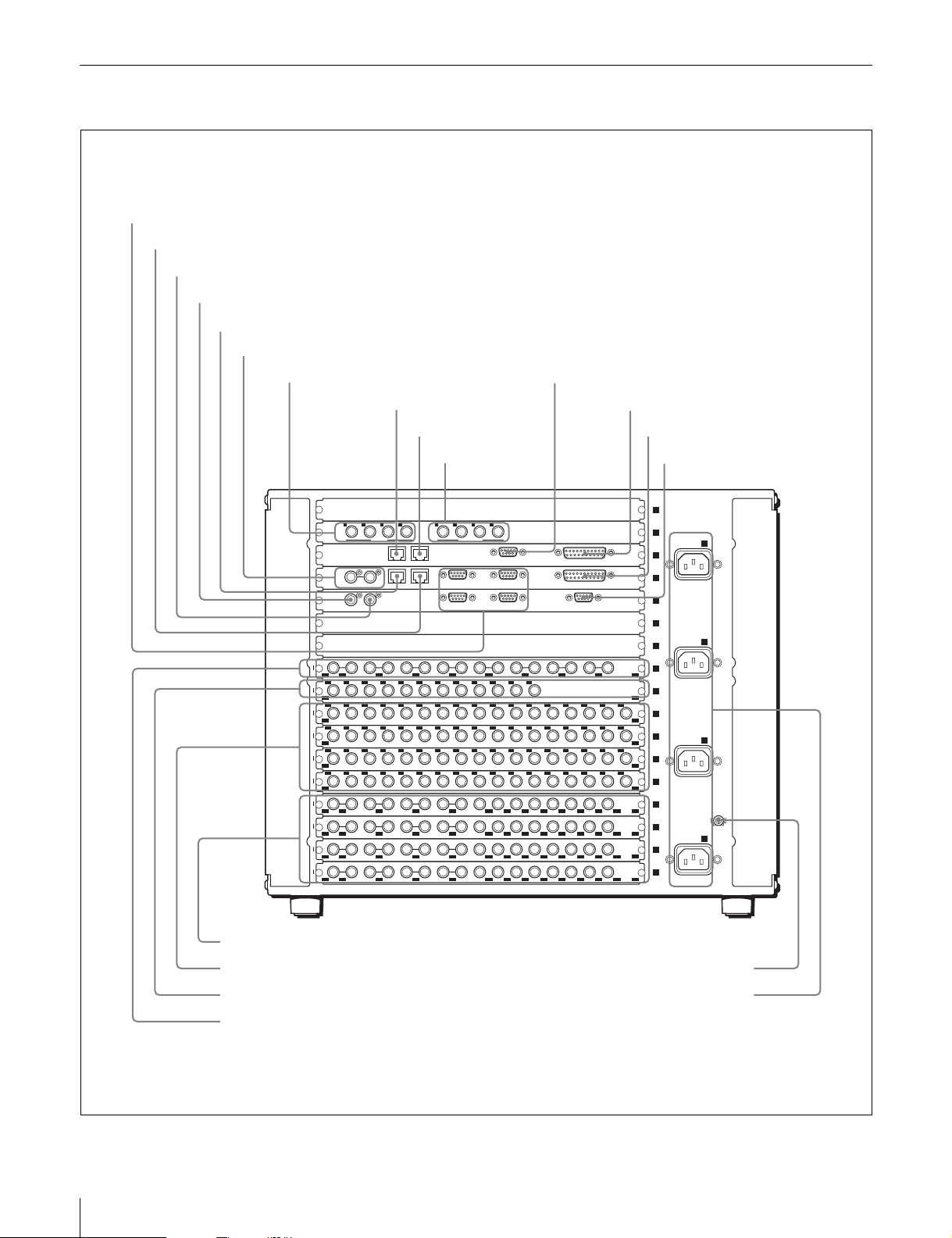
DVS-9000 Rear Panel
1SWITCHER REMOTE 1 to 4 connectors
2SWITCHER CTRL connector
3 EXT connector
4REF OUT connector
5SWITCHER DATA connector
6REF IN connectors
7DME EXT IN 1 to 4 connectors
qaDME REMOTE connector
8DME DATA connector
9DME CTRL connector
0 DME MONI OUT
1 to 4 connectors
1 2 3 4 1 2 3 4
EXT IN
DATA CTRL
DATA CTRL
REF OUT
EXT
49
56
OUT SD
1 2 3 4 5 6 7 8
69
70 71 72 73 74 75 76 77 78 79 80
69
80
IN
1
2 3 4 5 6 7 8 9 10 11 12 13 14 15 16 17
1
17
IN
1
2 3 4 5 6 7 8 9 10 11 12 13 14 15 16 17
18
34
IN
1
2 3 4 5 6 7 8 9 10 11 12 13 14 15 16 17
35
51
IN
1
2 3 4 5 6 7 8 9 10 11 12 13 14 15 16 17
52
68
IN
1
12
1 2 3 4 5 7 9 11 126 8 10
OUT
13
24
1 2 3 4 5 7 9 11 126 8 10
OUT
25
36
1 2 3 4 5 7 9 11 126 8 10
OUT
37
48
1 2 3 4 5 7 9 11 126 8 10
OUT
MONI OUT
REMOTE GPI
REMOTE 2 REMOTE 1 GPIREF IN
REMOTE 4 REMOTE 3 TERMINAL
qsDME GPI connector
qdSWITCHER GPI connector
qfTERMINAL connector
1
2
- AC IN
- AC IN
- AC IN
- AC IN
A
B
C
U
D
3
4
5
6
7
8
9
SD
10
SD
11
SD
12
SD
13
SD
14
SD
15
SD
16
SD
17
SD
qjOUTPUTS 1 to 48 connectors
qkPRIMARY INPUTS 1 to 68 connectors
qlEXTEND INPUTS 69 to 80 connectors
w;MONITOR OUTPUTS 49 to 56 connectors
8 Location and Function of Parts
qgU terminal
qh-AC IN A, B, C, D connectors
Page 9

a SWITCHER REMOTE 1 to 4 connectors
(D-sub 9-pin, RS-422A)
Used to control the DVS-9000 AUX bus from external
devices, and to operate the DVS-9000 from editing control
systems such as the BVE-9100.
Specify the types of connected devices on the center
control panel.
b SWITCHER CTRL (Switcher Control) connector
(RJ-45)
Connect to an Ethernet switch*.
The DVS-9000 System is connected in the same way to the
Ethernet switch to form a network for exchange of signals
between the devices.
This network is used primarily to control the various
devices from the center control panel.
* For information about Ethernet switches that can be used in an DVS-9000
system, contact your Sony service representative.
* Ethernet is a trademark of XEROX Corporation.
For more information about Ethernet switch connectors,
see “DVS-9000 System Configuration” (page 15).
For detailed information about setting up the Ethernet
switch, refer to the documentation supplied with the
Ethernet switch.
Caution
When using a LAN cable: For safety, do not connect to a
connector for peripheral device wiring that might have
excessive voltage.
c EXT (extension) connector (BNC type)
Used to expand inputs by connecting devices such as an
HDS-X series routing switcher.
d REF OUT (reference video output) connector
(BNC type)
Output analog sync signals.
e SWITCHER DATA connector (RJ-45)
Connect to an Ethernet switch.
The DVS-9000 System is connected in the same way to the
Ethernet switch to form a network for exchange of signals
between the devices.
This network is used primarily for exchange of various
types of data (key frame effects, snapshots, etc.) and still
pictures of frame memory.
two connectors have a loop-through configuration.
Signal input to one connector can be output from the other
connector. If you will not be using the loop-through
output, be sure to terminate the unused connector with the
supplied 75Ω terminator.
g DME EXT IN (Digital Multi Effects External
input) 1 to 4 connectors (BNC type) (BKDS-9470)
Connectors for four serial digital video signal inputs.
Dedicated input for DME external video.
h DME DATA (Digital Multi Effects Data) connector
(RJ-45) (BKDS-9470)
Connect to an Ethernet switch.
The DVS-9000 System is connected in the same way to the
Ethernet switch to form a network for exchange of signals
between the devices.
Caution
When using a LAN cable: For safety, do not connect to a
connector for peripheral device wiring that might have
excessive voltage.
i DME CTRL (Digital Multi Effects Control)
connector (RJ-45) (BKDS-9470)
Connect to an Ethernet switch.
The DVS-9000 System is connected in the same way to the
Ethernet switch to form a network for exchange of signals
between the devices.
This network is used primarily to control the various
devices from the center control panel.
Caution
When using a LAN cable: For safety, do not connect to a
connector for peripheral device wiring that might have
excessive voltage.
j DME MONI OUT (Digital Multi Effects Monitor
Output) 1 to 4 connectors (BNC type) (BKDS-9470)
Connectors for four serial digital video signal outputs.
These connectors allow you to monitor any desired output
signal with the DME signal (video, key, or with graphics).
k DME REMOTE (Digital Multi Effects Remote)
connector (D-sub 9-pin, RS-422A) (BKDS-9470)
When a BKDS-9470 is installed, enables control of DME
operations from remote devices.
Caution
When using a LAN cable: For safety, do not connect to a
connector for peripheral device wiring that might have
excessive voltage.
f REF IN (reference signal input) connectors
(BNC type)
If you wish to synchronize this unit to an external reference
signal, input a black burst signal or analog sync signal. The
l DME GPI (Digital Multi Effects General Purpose
Interface) connector (D-sub 25-pin) (BKDS-9470)
Connect to external devices for input and output of trigger
signals. Up to eight inputs and eight outputs are possible,
with input and output conditions set on the center control
panel.
9Location and Function of Parts
Page 10

m SWITCHER GPI (Switcher General Purpose
Interface) connector (D-sub 25-pin)
Connect to external devices for input and output of trigger
signals. Up to eight inputs and eight outputs are possible,
with input and output conditions set on the center control
panel.
n TERMINAL connector (D-sub 9-pin, RS-232C)
This connetor is used for factory adjustments.
o U (signal ground) terminal
Connect to the system ground.
p - AC IN (AC power input) A, B, C, D connectors
(3-pin)
Connect to 100 to 240 V AC power supply with the
optional AC power cords.
Depending on the system’s configuration when shipped,
there may be no optional HK-PSU04 Power Supply Units
installed. In that case, the AC IN C and D connectors is not
used.
Caution
For information about installing an HK-PSU04, contact
your Sony service representative.
t MONITOR OUTPUTS 49 to 56 connectors
(BNC type) (BKDS-9161)
Use these connectors as outputs for primary input monitors
or as auxiliary outputs for external devices.
These connectors are effective if you wish to output
primary inputs with as little delay as possible.
q OUTPUTS 1 to 48 connectors (BNC type)
(BKDS-9160)
These connectors output serial digital signals. They can be
freely assigned to program output, preview output, AUX
output and so on.
There are two BNC connectors for the lower numbers on
each slot (1 to 4, 13 to 16, 25 to 28, 37 to 40) and one BNC
connector for the upper numbers (5 to 12, 17 to 24, 29 to
36, 41 to 48).
Make output assignments using the center control panel of
the DVS-9000 system.
The number of connectors varies depending on the number
of BKDS-9160 sets installed.
Refer to the User’s Guide for information about signals
that may be assigned.
r PRIMARY INPUTS 1 to 68 connectors (BNC type)
(MKS-8110SD)
These connector accept up to 68 serial digital video signal
inputs. The number of connectors varies depending on the
number of MKS-8110SD boards installed.
s EXTEND INPUTS 69 to 80 connectors (BNC type)
(MKS-8111SD)
These connectors accept up to 12 expansion serial digital
video signal inputs.
Use these connectors when 69 or more inputs are required.
10 Location and Function of Parts
Page 11

DVS-9000SF Front Panel
Power A, B switches and status indicator
Power A, B switches and status indicators
The POWER switches turn the unit on and off. The unit is
powered on when the POWER switches are on the “?” side,
and powered off when the POWER switches are on the
“a” side. The status indicators light in green when the unit
is powered on.
Depending on the system’s configuration when shipped,
there may be no optional HK-PSU04 Power Supply Unit
installed. In this case, the only available POWER switch is
A (there is no switch B).
The unit is powered on when either of the two POWER
switches (A or B) is turned on.
With an HK-PSU04 unit installed, the system continues to
function normally as long as either of the two power
supply units is operating normally.
POWER A
POWER B
Caution
When installing the HK-PSU04 in your unit, be sure to
contact your Sony service representative.
Note
If a status indicator does not light when you turn a POWER
switch on, there may be a fault in the power circuits. Turn
the POWER switch off and contact your Sony service
representative.
11Location and Function of Parts
Page 12

DVS-9000SF Rear Panel
1EXT connector
2REF OUT connector
3SWITCHER CTRL connector
4SWITCHER DATA connector
5REF IN connectors
6DME EXT IN 1 to 4 connectors
123 4 1 2 3 4
REF OUT
1
12
1 2 3 4 5 7 9 11 126 8 10
OUT
13
24
1 2 3 4 5 7 9 11 126 8 10
OUT
1
2 3 4 5 6 7 8 9 10 11 12 13 14 15 16 17
1
17
IN
1
2 3 4 5 6 7 8 9 10 11 12 13 14 15 16 17
18
34
IN
7DME DATA connector
8DME CTRL connector
9 DME MONI OUT
1 to 4
connectors
EXT IN
DATA CTRL
DATA CTRL
EXT
MONI OUT
REMOTE 2 REMOTE 1 GPIREF IN
REMOTE 4 REMOTE 3 TERMINAL
0DME REMOTE connector
REMOTE GPI
qaDME GPI connector
qsSWITCHER GPI connector
qdSWITCHER REMOTE 1 to 4 connectors
qfTERMINAL connector
1
2
3
- AC IN
- AC IN
A
B
U
4
5
SD
6
SD
7
SD
8
SD
qjPRIMARY INPUTS 1 to 34 connectors
qkOUTPUTS 1 to 24 connectors
a EXT (extension) connector (BNC type)
Used to expand inputs by connecting devices such as an
HDS-X series routing switcher.
b REF OUT (reference video output) connector
(BNC type)
Output analog sync signals.
c SWITCHER CTRL (Switcher Control) connector
(RJ-45)
Connect to an Ethernet switch*.
The DVS-9000 System is connected in the same way to the
Ethernet switch to form a network for exchange of signals
between the devices.
This network is used primarily to control the various
devices from the center control panel.
qgU terminal
qh-AC IN A, B connectors
* For information about Ethernet switches that can be used in an DVS-9000
system, contact your Sony service representative.
For more information about Ethernet switch connectors,
see “DVS-9000 System Configuration” (page 15).
For detailed information about setting up the Ethernet
switch, refer to the documentation supplied with the
Ethernet switch.
Caution
When using a LAN cable: For safety, do not connect to a
connector for peripheral device wiring that might have
excessive voltage.
12 Location and Function of Parts
Page 13

d SWITCHER DATA connector (RJ-45)
Connect to an Ethernet switch.
The DVS-9000 System is connected in the same way to the
Ethernet switch to form a network for exchange of signals
between the devices. This network is used primarily for
exchange of various types of data (key frame effects,
snapshots, etc.) and still pictures of frame memory.
Caution
When using a LAN cable: For safety, do not connect to a
connector for peripheral device wiring that might have
excessive voltage.
e REF IN (reference signal input) connectors (BNC
type)
If you wish to synchronize this unit to an external reference
signal, input a black burst signal or analog sync signal.
The two connectors have a loop-through configuration.
Signal input to one connector can be output from the other
connector. If you will not be using the loop-through
output, be sure to terminate the unused connector with the
supplied 75Ω terminator.
f DME EXT IN (Digital Multi Effects External
input) 1 to 4 connectors (BNC type) (BKDS-9470)
Connectors for four serial digital video signal inputs.
Dedicated input for DME external video.
g DME DATA (Digital Multi Effects Data) connector
(RJ-45) (BKDS-9470)
Connect to an Ethernet switch.
The DVS-9000 System is connected in the same way to the
Ethernet switch to form a network for exchange of signals
between the devices.
i DME MONI OUT (Digital Multi Effects Monitor
Output) 1 to 4 connectors (BNC type) (BKDS-9470)
Connectors for four serial digital video signal outputs.
These connectors allow you to monitor any desired output
signal with the DME signal (video, key, or with graphics).
j DME REMOTE (Digital Multi Effects Remote)
connector (D-sub 9-pin, RS-422A) (BKDS-9470)
When a BKDS-9470 DME Board Set is installed, use this
connector to control the unit from an external device.
k DME GPI (Digital Multi Effects General Purpose
Interface) connector (D-sub 25-pin) (BKDS-9470)
Connect to external devices for input and output of trigger
signals. Up to eight inputs and eight outputs are possible,
with input and output conditions set on the center control
panel.
l SWITCHER GPI (Switcher General Puropose
Interface) connector (D-sub 25-pin)
Connect to external devices for input and output of trigger
signals. Up to eight inputs and eight outputs are possible,
with input and output conditions set on the center control
panel.
m SWITCHER REMOTE 1 to 4 connectors
(D-sub 9-pin, RS-422A)
Used to control the DVS-9000SF AUX bus from external
devices, and to operate the DVS-9000SF from editing
control systems such as the BVE-9100.
Specify the types of connected devices on the center
control panel.
n TERMINAL connector (D-sub 9-pin, RS-232C)
This connetor is used for factory adjustments.
Caution
When using a LAN cable: For safety, do not connect to a
connector for peripheral device wiring that might have
excessive voltage.
h DME CTRL (Digital Multi Effects Control)
connector (RJ-45) (BKDS-9470)
Connect to an Ethernet switch.
The DVS-9000 System is connected in the same way to the
Ethernet switch to form a network for exchange of signals
between the devices.
This network is used primarily to control the various
devices from the center control panel.
Caution
When using a LAN cable: For safety, do not connect to a
connector for peripheral device wiring that might have
excessive voltage.
o U (signal ground) terminal
Connect to the system ground.
p -AC IN (AC power input) A, B connectors (3-pin)
Connect to 100 to 240 V AC power supply with the
optional AC power cords.
Depending on the system’s configuration when shipped,
there may be no optional HK-PSU04 Power Supply Unit
installed. In that case, the AC IN B connector is not used.
Caution
For information about installing an HK-PSU04, contact
your Sony service representative.
q PRIMARY INPUTS 1 to 34 connectors (BNC type)
(MKS-8110SD)
These connector accept up to 34 serial digital video signal
inputs. The number of connectors varies depending on the
number of MKS-8110SD boards installed.
13Location and Function of Parts
Page 14

r OUTPUTS 1 to 24 connectors (BNC type)
(BKDS-9162)
These connectors output serial digital signals. They can be
freely assigned to program output, preview output, AUX
output and so on.
There are two BNC connectors for the lower numbers on
each slot (1 to 4, 13 to 16) and one BNC connector for the
upper numbers (5 to 12, 17 to 24) (the BKDS-9162 is
required 13 to 24).
Make output assignments using the center control panel of
the DVS-9000 system.
Refer to the User’s Guide for information about signals
that may be assigned.
14 Location and Function of Parts
Page 15

Example System Configuration
DVS-9000 System Configuration
The figure below shows the configuration of a DVS-9000
system.
SWITCHER
REMOTE
1
2
- AC IN
A
3
4
5
6
- AC IN
B
7
8
9
10
11
- AC IN
C
12
13
14
15
U
- AC IN
D
16
17
a)
Reference video
signal
Ethernet switch
DME
DATA
SWITCHER DATA
123 4 1 2 3 4
REF OUT
49
56
OUT SD
1 2 3 4 5 6 7 8
69
70 71 72 73 74 75 76 77 78 79 80
69
80
IN
1
2 3 4 5 6 7 8 9 10 11 12 13 14 15 16 17
1
17
IN
1
2 3 4 5 6 7 8 9 10 11 12 13 14 15 16 17
18
34
IN
1
2 3 4 5 6 7 8 9 10 11 12 13 14 15 16 17
35
51
IN
1
2 3 4 5 6 7 8 9 10 11 12 13 14 15 16 17
52
68
IN
1
12
1 2 3 4 5 7 9 11 126 8 10
OUT
13
24
1 2 3 4 5 7 9 11 126 8 10
OUT
25
36
1 2 3 4 5 7 9 11 126 8 10
OUT
37
48
1 2 3 4 5 7 9 11 126 8 10
OUT
a)
DME
CTRL
SWITCHER CTRL
EXT IN
MONI OUT
DATA CTRL
REMOTE 2 REMOTE 1 GPIREF IN
DATA CTRL
REMOTE 4 REMOTE 3 TERMINAL
EXT
Ethernet switch
REMOTE GPI
DME
REMOTE
SD
SD
SD
SD
SD
SD
SD
SD
SD
The same type of configuration is possible with a DVS9000SF system.
BVE-9100 Editing
Control System
CTRL
PERIPH
REMOTE
b)
BKS-R Series
DATA
MKS-8010 System
Control Unit
Reference video
b)
signal
a)It is recommended that the
CTRL and DATA LAN networks
be configured by connecting
separate Ethernet switches for
each LAN.
DVS-9000-C Switcher
Processor Pack
b)Terminate with the supplied
75Ω terminators. Terminators
are supplied in the product
package.
HDS-X Series
DCU-8000 Device Control Unit Pack
VTR
DDR
PERIPH
Reference
video signal
Audio Mixer
Cross cable
Cable with BNC connectors
b)
15Example System Configuration
Page 16

Flow of Video Signals
The figure below shows the flow of video signals in a
DVS-9000 system.
Camera,
VTR, routing
switcher
Monitor
Camera,
VTR, routing
switcher
Monitor
Reference video signal
MONITOR OUTPUTS
PRIMARY INPUTS
EXTEND INPUTS
OUTPUTS
b)
DME EXT IN
1 - 4
123 4 1 2 3 4
REF OUT
49 - 56
1 - 68/
69 - 80
1 - 48
49
56
OUT SD
1 2 3 4 5 6 7 8
69
70 71 72 73 74 75 76 77 78 79 80
69
80
IN
1
2 3 4 5 6 7 8 9 10 11 12 13 14 15 16 17
1
17
IN
1
2 3 4 5 6 7 8 9 10 11 12 13 14 15 16 17
18
34
IN
1
2 3 4 5 6 7 8 9 10 11 12 13 14 15 16 17
35
51
IN
1
2 3 4 5 6 7 8 9 10 11 12 13 14 15 16 17
52
68
IN
1
12
1 2 3 4 5 7 9 11 126 8 10
OUT
13
24
1 2 3 4 5 7 9 11 126 8 10
OUT
25
36
1 2 3 4 5 7 9 11 126 8 10
OUT
37
48
1 2 3 4 5 7 9 11 126 8 10
OUT
DVS-9000-C Switcher Processor Pack
EXT IN
DATA CTRL
DATA CTRL
EXT
The flow of signals is the same in a DVS-9000SF system.
Monitor
DME MONI OUT
1 - 4
1
MONI OUT
REMOTE GPI
REMOTE 2 REMOTE 1 GPIREF IN
REMOTE 4 REMOTE 3 TERMINAL
2
- AC IN
A
3
4
5
6
- AC IN
B
7
8
9
SD
10
SD
11
- AC IN
C
SD
12
SD
13
SD
14
SD
15
U
SD
- AC IN
D
16
SD
17
SD
100 to 240 V AC power supply
a)
VTR
a)For the AC power cord of the DVS-9000 Production Switcher Processor,
refer to “Accessories not supplied” (page 18).
b)Terminate with the supplied 75Ω terminators.
Terminators are supplied in the product package.
Video input signal
Video output signal
AC power supply
16 Example System Configuration
Page 17

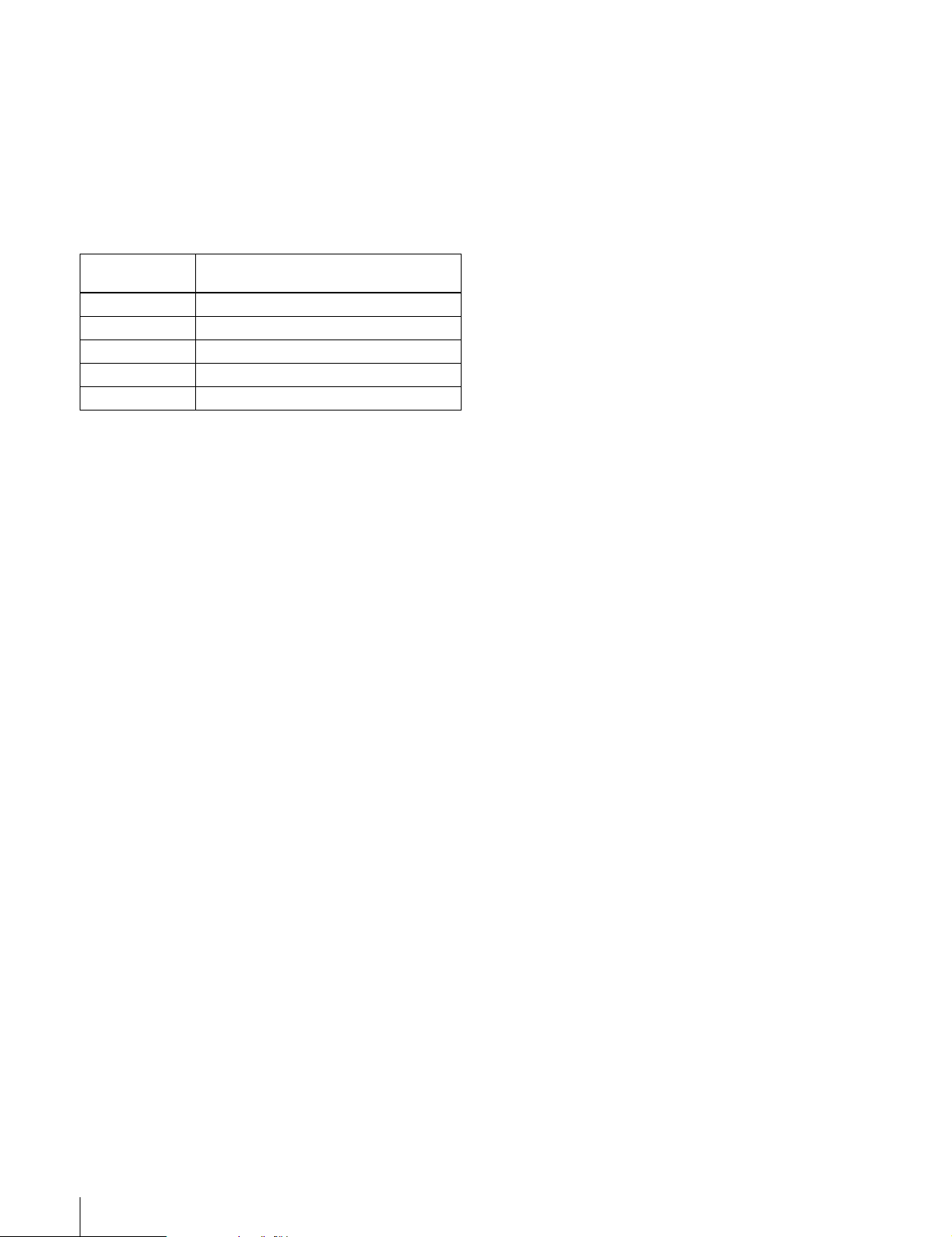
Power Supply Unit Status Indicators
The power supply unit status indicators show the status of
the power supply unit during operation and when the unit
is powered on. Whenever a power error is detected, it is
reflected immediately by the indicator.
Meaning of status indicator displays
Indicator
color
Green Lit Operating normally −
Red Lit P ower supply unit f an
− Not lit Power supply unit
Notes
• When the unit is powered on, the status indicators may
light momentarily in red and a whining sound may be
heard. This is not a malfunction.When some of the
power supply units are off and some are on, the status
indicators of the units which are off may light in red.
This is not a malfunction.
• Power all of the installed power supply units on.
Status Description Steps to take
fault
fault
Exchange the
fan unit
Exchange the
power unit
17Power Supply Unit Status Indicators
Page 18

Specifications
The following specifications show the reference
performance for this unit and individual option boards/
modules.
Design and specifications are subject to change without
notice.
DVS-9000 Production Switcher Processor
Complies with RS-232C standard
Data transfer rate: 9600 bps
EXT BNC type, 75Ω
S-BUS data transfer rate: 312/1250 Kbps
Reference input and output
REF IN BNC type, 75Ω, with loop-through
output
Analog black burst/analog sync
REF OUT BNC type, 75Ω
Analog sync
Signal level ±300 mV ±10%
Phase variation range
−90H to +90H
General
Power requirements
100 to 240 V AC, 50/60 Hz
Current consumption
100 V: 8.5 A, 240 V: 4.2A
Peak inrush current
(1) Power ON, current probe method:
60 A (100 V), 110 A (240 V)
(2) Hot switching inrush current,
measured in accordance with
European standard EN55103-1: 40 A
(230 V)
Operating temperature
5ºC to 40ºC (41ºF to 104ºF)
Performance guaranteed temperature
10ºC to 35ºC (50ºF to 95ºF)
Storage temperature
−20ºC to +60ºC (−4ºF to +140ºF)
Operating humidity
10% to 90%
Dimensions (w/h/d, excluding projections)
482×354×520 mm
(19×14×20
Mass Approx. 43 kg (9 lb 7 oz)
1
/2 inches)
Control connectors
CTRL RJ-45
Complies with 100Base-TX standard
DATA RJ-45
Complies with 100Base-TX standard
REMOTE 1, 2, 3, 4
D-sub 9-pin, female
Comply with RS-422A standard
Data transfer rate: 38.4 Kbps
GPI D-sub 25-pin, female
TTL inputs: 8
Relay contact outputs: 4 (30V AC/DC,
0.1A)
Open collector outputs: 4
TERMINAL D-sub 9-pin, female
Video input
Inputs 17 (BNC type)
Signal format SMPTE259M-C
Signal level 0.8 V p-p ±10%
Signal tansfer rate
270 Mbps
Return loss 15 dB
Cable length 200 m (5C-2V cable, BELDEN8281 or
equivalent)
Video output
Outputs 24 (BNC type): 1 to 4 and 13 to 16, each
with 2 outputs
Signal format SMPTE259M-C
Signal level 0.8 V p-p ±10%
Signal tansfer rate
270 Mbps
AC input
AC IN A, B, C, D
3-pin AC connector
Accessories supplied
75Ω terminator (1)
Bracket (4)
Support angle (2)
Screw (+B4×10) (8)
Screw (+PSW 4×10) (8)
Operation Manual (1)
Installation Manual (1)
Accessories not supplied
AC power cord (for USA and Canada only) (125 V 10 A
2.4 m (8 ft)) (Part No.: 1-557-377-11)
AC power cord (for Europe only) (250 V 10 A 2.4 m (8 ft))
(Part No.: 1-782-929-21)
18 Specifications
Page 19

DVS-9000SF Production Switcher Processor
Analog sync
Signal level ±300 mV ±10%
Phase variation range
−90H to +90H
General
Power requirements
100 to 240 V AC, 50/60 Hz
Current consumption
100 V: 5.4 A, 240 V: 2.5 A
Peak inrush current
(1) Power ON, current probe method:
60 A (100 V), 110 A (240 V)
(2) Hot switching inrush current,
measured in accordance with
European standard EN55103-1: 40 A
(230 V)
Operating temperature
5ºC to 40ºC (41ºF to 104ºF)
Performance guaranteed temperature
10ºC to 35ºC (50ºF to 95ºF)
Storage temperature
−20ºC to +60ºC (−4ºF to +140ºF)
Operating humidity
10% to 90%
Dimensions (w/h/d, excluding projections)
482×177×520 mm
(19×7×20
Mass Approx. 25 kg (5 lb 8 oz)
1
/2 inches)
Control connectors
CTRL RJ-45
Complies with 100Base-TX standard
DATA RJ-45
Complies with 100Base-TX standard
REMOTE 1, 2, 3, 4
D-sub 9-pin, female
Comply with RS-422A standard
Data transfer rate: 38.4 Kbps
GPI D-sub 25-pin, female
TTL inputs: 8
Relay contact outputs: 4 (30V AC/DC,
0.1A)
Open collector outputs: 4
TERMINAL D-sub 9-pin, female
Complies with RS-232C standard
Data transfer rate: 9600 bps
EXT BNC type, 75Ω
S-BUS data transfer rate: 312/1250 Kbps
Reference input and output
REF IN BNC type, 75Ω, with loop-through
output
Analog black burst/analog sync
REF OUT BNC type, 75Ω
Video input
Inputs 17 (BNC type)
Signal format SMPTE259M-C
Signal level 0.8 V p-p ±10%
Signal tansfer rate
270 Mbps
Return loss 15 dB
Cable length 200 m (5C-2V cable, BELDEN8281 or
equivalent)
Video output
Outputs 12 (BNC type): 1 to 4, each with 2
outputs
Signal format SMPTE259M-C
Signal level 0.8 V p-p ±10%
Signal tansfer rate
270 Mbps
AC input
AC IN A, B 3-pin AC connector
Accessories supplied
75Ω terminator (1)
Bracket (4)
Support angle (2)
Screw (+B4×10) (8)
Screw (+PSW 4×10) (8)
Operation Manual (1)
Installation Manual (1)
Accessories not supplied
AC power cord (for USA and Canada only) (125 V 10 A
2.4 m (8 ft)) (Part No.: 1-557-377-11)
AC power cord (for Europe only) (250 V 10 A 2.4 m (8 ft))
(Part No.: 1-782-929-21)
BKDS-9160 24 Output Board Set
General
Power requirements
12 V DC
Power consumption
Max. 50 W
Dimensions (w/h)
OUT board: 317×380 mm
1
/2×15 inches)
(12
19Specifications
Page 20

CN board: 274×94 mm
7
/8×33/4 inches) (using 2 boards)
(10
Mass Approx. 2 kg (4 lb 6 oz)
Output
Outputs 24 (BNC type), 1 to 4 and 13 to 16, each
with 2 outputs
Signal format SMPTE259M-C
Signal level 0.8 Vp-p ±10%
Signal transfer rate
270 Mbps
Output
Outputs 12 (BNC type), 1 to 4, each with 2 outputs
Signal format SMPTE259M-C
Signal level 0.8 Vp-p ±10%
Signal transfer rate
270 Mbps
Accessories supplied
Operation and Installation Guide (1)
(supplied only when product is purchased separately)
Accessories supplied
Operation and Installation Guide (1)
(supplied only when product is purchased separately)
BKDS-9161 Monitor Output Board
General
Power requirements
12 V DC
Power consumption
Max. 10 W
Dimensions (w/d, excluding projections)
274×94 mm (10
Mass Approx. 1 kg (2 lb 3 oz)
7
/8×33/4 inches)
Output
Outputs 8 (BNC type), each with 2 outputs
Signal format SMPTE259M-C
Signal level 0.8 Vp-p ±10%
Signal transfer rate
270 Mbps
Accessories supplied
Operation and Installation Guide (1)
(supplied only when product is purchased separately)
BKDS-9162 12 Output Connector Board
General
Power requirements
12 V DC
Power consumption
Max. 5 W
Dimensions (w/d, excluding projections)
274×94 mm (10
Mass Approx. 1 kg (2 lb 3 oz)
7
/8×33/4 inches)
BKDS-9210 Mix/Effect Board
Power requirements
12 V DC
Power consumption
Max. 80 W
Dimensions (w/d, excluding projections)
317×380 mm (12
Mass Approx. 2 kg (4 lb 6 oz)
Accessories supplied
Operation and Installation Guide (1)
(supplied only when product is
purchased separately)
1
/2×15 inches)
BKDS-9470 DME Board Set
General
Power requirements
12 V DC
Power consumption
Max. 100 W
Dimensions (w/h)
DVP board: 317×380 mm
1
/2×15 inches)
(12
CA board: 317×380 mm
1
/2×15 inches)
(12
CN board: 274×94 mm
7
/8×33/4 inches) (When used with
(10
two boards)
Mass Approx. 4 kg (8 lb 13 oz)
Remote Control connectors
CTRL RJ-45
Complies with 100Base-TX standard
DATA RJ-45
Complies with 100Base-TX standard
REMOTE D-sub 9-pin, female
Complies with RS-422A standard
Data transfer rate: 38.4 Kbps
GPI D-sub 25-pin, female
TTL inputs: 8
20 Specifications
Page 21

Relay contact outputs: 4 (30V AC/DC,
0.1A)
Open collector outputs: 4
MKS-8111SD Additional 12 Input Board
Input
Inputs 4 (BNC type)
Signal format SMPTE259M-C
Signal level 0.8 V p-p ±10%
Signal tansfer rate
270 Mbps
Return loss 15 dB
Cable length 200 m (5C-2V cable, BELDEN8281 or
equivalent)
Output
Outputs 4 (BNC type)
Signal format SMPTE259M-C
Signal level 0.8 V p-p ±10%
Signal tansfer rate
270 Mbps
Accessories supplied
Operation and Installation Guide (1)
(supplied only when product is purchased separately)
MKS-8110SD 17 Input Board
General
Power requirements
12 V DC
Power consumption
Max. 10 W
Dimensions (w/h)
274×94 mm (10
Mass Approx. 1 kg (2 lb 3 oz)
7
/8×33/4 inches)
Input
Inputs 12 (BNC type)
Signal format SMPTE259M-C
Signal level 0.8 V p-p ±10%
Signal tansfer rate
270 Mbps
Return loss 15 dB
Cable length 200 m (5C-2V cable, BELDEN8281 or
equivalent)
Accessories supplied
Operation and Installation Guide (1)
(supplied only when product is purchased separately)
General
Power requirements
12 V DC
Power consumption
Max. 10 W
Dimensions (w/h)
274×94 mm (10
Mass Approx. 1 kg (2 lb 3 oz)
7
/8×33/4 inches)
Input
Inputs 17 (BNC type)
Signal format SMPTE259M-C
Signal level 0.8 V p-p ±10%
Signal tansfer rate
270 Mbps
Return loss 15 dB
Cable length 200 m (5C-2V cable, BELDEN8281 or
equivalent)
Accessories supplied
Operation and Installation Guide (1)
(supplied only when product is purchased separately)
HK-PSU04 Power Supply Unit
Power requirements
100 to 240 V AC, 50/60 Hz
Power consumption
100 V: 10 A, 240 V: 5 A
Peak inrush current
(1) Power ON, current probe method:
60 A (100 V), 110 A (240 V)
(2) Hot switching inrush current,
measured in accordance with
European standard EN55103-1: 40 A
(230 V)
Output power 12 V DC ±0.5V
Secondary power supply
Max. 60 A
Dimensions (w/h/d)
94×83×396 mm (3
Mass Approx. 3 kg (6 lb 9 oz)
Accessories supplied
Operation and Installation Guide (1)
(supplied only when product is
purchased separately)
3
/4×33/8×155/8 inches)
21Specifications
Page 22

22 Specifications
Page 23

The material contained in this manual consists of information
that is the property of Sony Corporation and is intended solely
for use by the purchasers of the equipment described in this
manual.
Sony Corporation expressly prohibits the duplication of any
portion of this manual or the use thereof for any purpose other
than the operation or maintenance of the equipment described
in this manual without the express written permission of Sony
Corporation.
Le matériel contenu dans ce manuel consiste en informations
qui sont la propriété de Sony Corporation et sont destinées
exclusivement à l’usage des acquéreurs de l’équipement
décrit dans ce manuel.
Sony Corporation interdit formellement la copie de quelque
partie que ce soit de ce manuel ou son emploi pour tout autre
but que des opérations ou entretiens de l’équipement à moins
d’une permission écrite de Sony Corporation.
Das in dieser Anleitung enthaltene Material besteht aus
Informationen, die Eigentum der Sony Corporation sind, und
ausschließlich zum Gebrauch durch den Käufer der in dieser
Anleitung beschriebenen Ausrüstung bestimmt sind.
Die Sony Corporation untersagt ausdrücklich die
Vervielfältigung jeglicher Teile dieser Anleitung oder den
Gebrauch derselben für irgendeinen anderen Zweck als die
Bedienung oder Wartung der in dieser Anleitung
beschriebenen Ausrüstung ohne ausdrückliche schriftliche
Erlaubnis der Sony Corporation.
Page 24

DVS-9000
(WW)
3-690-433-01 (1)
Sony Corporation
B & P Company
Printed on recycled paper
Printed in Japan
2002.07.13
© 2002
 Loading...