

Sony DVPK-800-D Service manual

DVP-K800D
RMT-D106E
SERVICE MANUAL
• Refer to the OPERATION MANUAL (9-921-669-21) and
DVD MECHANISM OPERA TION MANUAL (9-921-669-31)
for DVD mechanism.
SPECIFICATIONS
Chinese Model
E Model
Hong kong Model
Spanish Model
Taiwan Model
MICROFILM
CD/DVD PLAYER

WARNING!!
WHEN SERVICING, DO NOT APPROACH THE LASER
EXIT WITH THE EYE TOO CLOSELY. IN CASE IT IS
NECESSARY T O CONFIRM LASER BEAM EMISSION,
BE SURE TO OBSERVE FROM A DIST ANCE OF MORE
THAN 25 cm FROM THE SURFACE OF THE OBJECTIVE
LENS ON THE OPTICAL PICK-UP BLOCK.
CAUTION:
The use of optical instrument with this product will increase eye
hazard.
CAUTION
Use of controls or adjustments or performance procedures other
than those specified herein may result in hazardous radiation
exposure.
SAFETY-RELATED COMPONENT WARNING!!
COMPONENTS IDENTIFIED BY MARK ! OR DOTTED LINE WITH
MARK ! ON THE SCHEMATIC DIAGRAMS AND IN THE PARTS
LIST ARE CRITICAL TO SAFE OPERATION. REPLACE THESE
COMPONENTS WITH SONY PARTS WHOSE PART NUMBERS
APPEAR AS SHOWN IN THIS MANUAL OR IN SUPPLEMENTS
PUBLISHED BY SONY.
SAFETY CHECK-OUT
After correcting the original service problem, perform the following
safety checks before releasing the set to the customer.
1. Check the area of your repair for unsoldered or poorly-soldered
connections. Check the entire board surface for solder splashes
and bridges.
2. Check the interboard wiring to ensure that no wires are
"pinched" or contact high-wattage resistors.
3. Look for unauthorized replacement parts, particularly
transistors, that were installed during a previous repair . Point
them out to the customer and recommend their replacement.
4. Look for parts which, through functioning, show obvious signs
of deterioration. Point them out to the customer and
recommend their replace-ment.
5. Check the B+ voltage to see it is at the values specified.
6. Flexible Circuit Board Repairing
• Keep the temperature of the soldering iron around 270˚C
during repairing.
• Do not touch the soldering iron on the same conductor of the
circuit board (within 3 times).
• Be careful not to apply force on the conductor when soldering
or unsoldering.
— 2 —

T ABLE OF CONTENTS
SERVICE NOTE
1. DISK REMOVAL PROCEDURE (at POWER OFF).................... 4
2. NOTE ON MOUNTING SLED MOTOR ................................. 4
3. REPLACING OPTICAL PICK-UP ............................................... 5
3-1. Handling .......................................................................................... 5
4. NOTE ON ASSEMBLING MECHANICAL DECK.................. 6
4-1. Application of Grease ..................................................................... 6
4-2. Cleaning Spindle Motor Turntable................................................. 7
4-3. Aligning Phase of Cam Gear and Drive Gear ................................ 7
4-4. Deformation of Insulator................................................................ 7
4-5. Note on connecting OPT Harness .................................................. 7
4-6. Note on Mounting FG-43 Board .................................................... 8
4-7. Note on Mounting TK-47 Board.................................................... 8
5. EMERGENCY CODE INDICATION ........................................... 8
5-1. Users are expected to take of the followings by thermselves
--- “C” code .................................................................................... 8
5-2. Consult Sony Service --- “E” code, E : YY: ZZ ............................. 8
1. GENERAL
Getting Started
Unpacking...........................................................................................................1-1
Hooking Up the System......................................................................................1-1
Necessary Setup Before Using the Player .......................................................... 1-1
Selecting the Language for On-screen Display .................................................. 1-1
Basic Operations
Playing a DVD....................................................................................................1-2
Playing a CD/VIDEO CD .................................................................................. 1-3
Enjouing Karaoke
Using Karaoke .................................................................................................... 1-4
Reserving Karaoke .............................................................................................1-4
Additing Richness to Your Voice (Karaoke Star) ...............................................1-5
Plaing Karaoke with Any Stereo Disc (Karaoke Pon) ........................................1-5
Using the On-Screem Dosplay ........................................................................... 1-5
Playing Discs in Various Modes
Using the On-Screen Display ............................................................................. 1-4
Using the Front Panel Display ............................................................................1-5
Playing Repeatedly (Repeat Play) ...................................................................... 1-6
Playing in Random Order (Shuffle Play) ...........................................................1-5
Creating Your Own Program (Program Play) ..................................................... 1-6
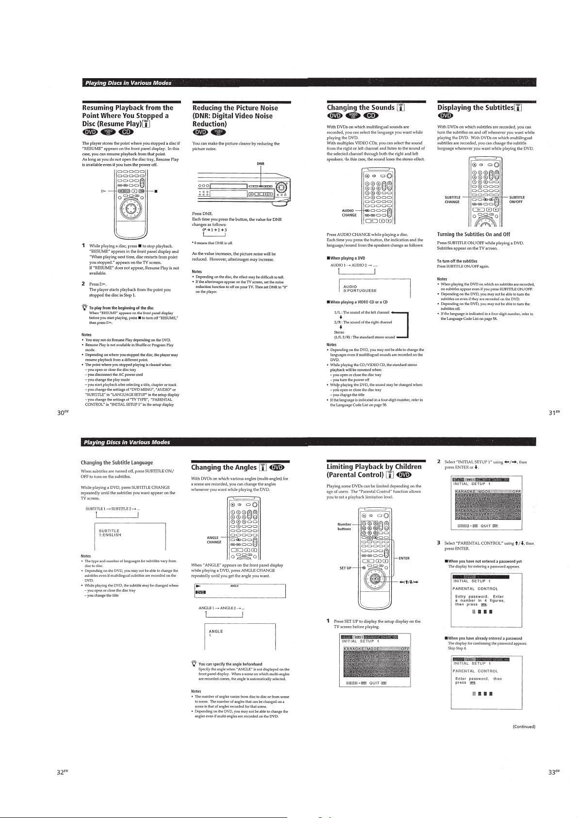
Resuming Playback from the Point Where
You Stopped a Disc (Resume Play) ....................................................................1-7
Reducing the Picture Noise
(DNR: Digital Video Noise Reduction)..............................................................1-7
Changing the Sounds .......................................................................................... 1-7
Displaying the Subtitles......................................................................................1-7
Changing the Angles...........................................................................................1-7
Limiting Playback by Children (Parental Control) ............................................ 1-7
Controlling the TV or the amplifier with
the Supplied Remote........................................................................................... 1-8
Settings and Adjustments
Using the Setup Display ..................................................................................... 1-8
Setting the Language for Displaying and Sound (LANGUAGE SETUP) .........1-9
Settings for Display (INITIAL SETUP 1).......................................................... 1-9
Settings for Sound (INITIAL SETUP 2) ............................................................1-9
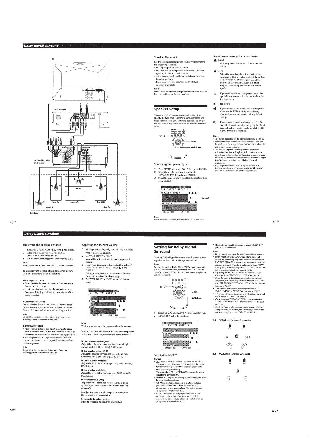
Dolby Digital Surround
What is Dolby Digital Surround? ....................................................................... 1-9
Speaker System Hookups ................................................................................... 1-9
Speaker Setup ................................................................................................... 1-10
Setting for Dolby Digital Surround .................................................................. 1-10
Additional Information
Precautions ....................................................................................................... 1-11
Notes on Discs .................................................................................................. 1-11
Troubleshooting................................................................................................ 1-11
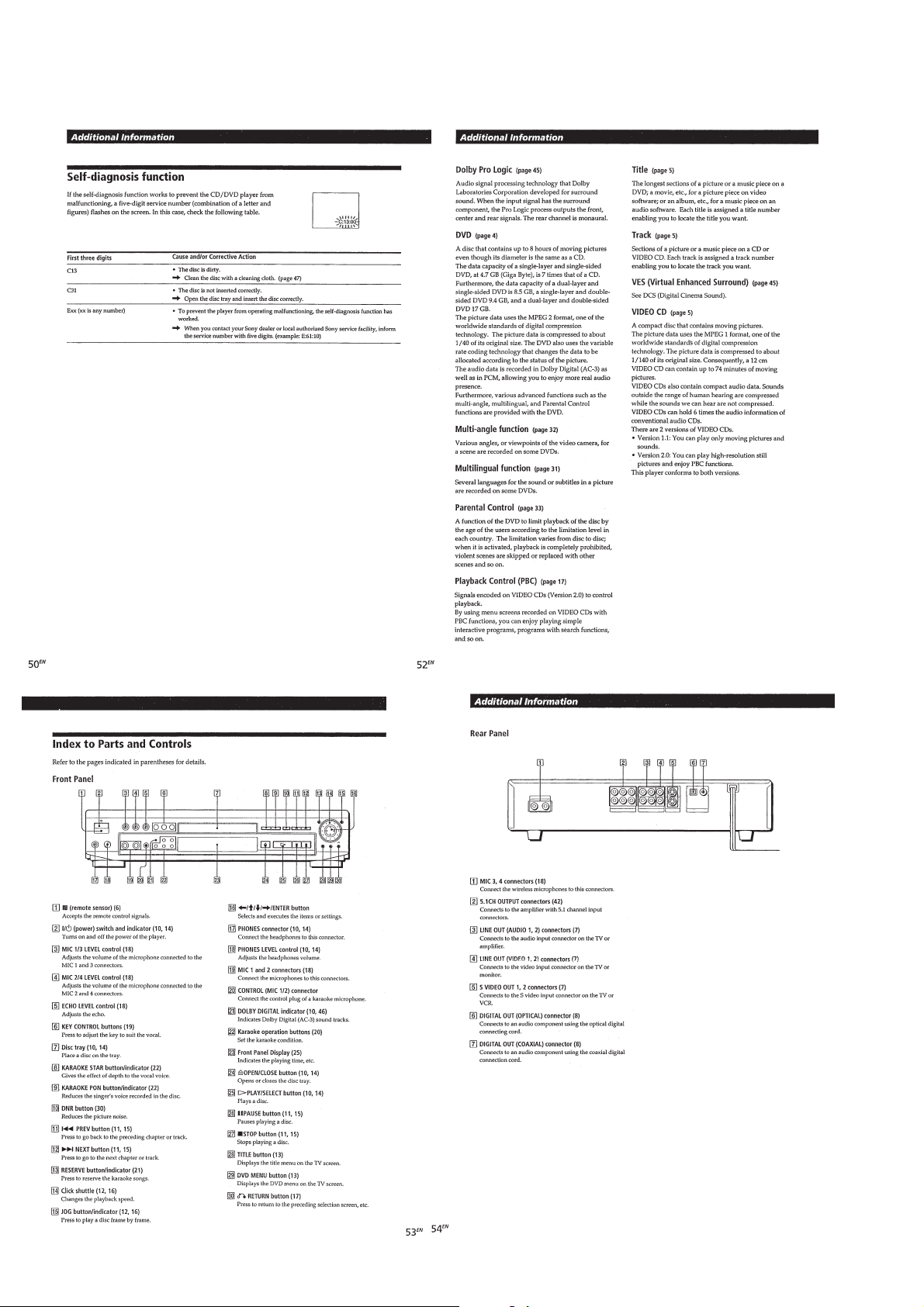
Self-diagnosis Function .................................................................................... 1-12
Index to Parts and Controls ..............................................................................1-12
Setup Display Item List .................................................................................... 1-13
Language Code List.......................................................................................... 1-13
2. DISASSEMBLY
2-1. UPPER CASE ............................................................................. 2-1
2-2. FRONT PANEL BLOCK ASSEMBLY ...................................... 2-1
2-3. AU-217 BOARD ......................................................................... 2-2
2-4. MB-78 BOARD ..........................................................................2-2
2-5. KR-35 BOARD ........................................................................... 2-3
2-6. POWER BLOCK ........................................................................2-3
2-7. TK-47 BOARD ........................................................................... 2-4
2-8. HP-116 BOARD, MC-115/VR-68 BOARD BLOCK,
FL-106 BOARD, FR-156 BOARD ............................................. 2-4
2-9. CIRCUIT BOARDS LOCATION ............................................... 2-5
3. BLOCK DIAGRAMS
3-1. OVERALL BLOCK DIAGRAM ................................................ 3-1
3-2. RF/SERVO BLOCK DIAGRAM................................................ 3-3
3-3. AUDIO BLOCK DIAGRAM ..................................................... 3-5
3-4. VIDEO BLOCK DIAGRAM...................................................... 3-7
3-5. SYSTEM CONTROL BLOCK DIAGRAM............................... 3-9
3-6. MODE CONTROL BLOCK DIAGRAM................................. 3-11
3-7. AC3 BLOCK DIAGRAM......................................................... 3-13
3-8. POWER SUPPLY BLOCK DIAGRAM ................................... 3-15
4. PRINTED WIRING BOARDS AND
SCHEMATIC DIAGRAMS
4-1. FRAME SCHEMATIC DIAGRAM ...........................................4-1
4-2. PRINTED WIRING BOARDS AND
SCHEMATIC DIAGRAMS........................................................ 4-3
• TK-47 (RF, SERVO) PRINTED WIRING BOARD ................ 4-4
• TK-47 (RF, SERVO) SCHEMATIC DIAGRAM ..................... 4-7
• MB-78 (VIDEO, SERVO/SYSTEM CONTROL, AUDIO)
PRINTED WIRING BOARD ...................................... 4-12
• MB-78 (DSP) SCHEMATIC DIAGRAM .............................. 4-17
• MB-78 (AV DECODER) SCHEMATIC DIAGRAM ............ 4-20
• MB-78 (VIDEO ENCODER) SCHEMATIC DIAGRAM ..... 4-23
• MB-78 (INTERFACE) SCHEMATIC DIAGRAM ................ 4-26
• MB-78 (MOTOR DRIVE) SCHEMATIC DIAGRAM .......... 4-29
• MB-78 (POWER SUPPLY) SCHEMATIC DIAGRAM ........4-31
• MB-78 (DIGITAL PROCESS 1)
SCHEMATIC DIAGRAM ...........................................4-33
• MB-78 (DIGITAL PROCESS 2)
SCHEMATIC DIAGRAM ...........................................4-37
• MB-78 (AC3 DECODER)
SCHEMATIC DIAGRAM ...........................................4-41
• AU-217 (VIDEO/AUDIO INPUT/OUTPUT)
SCHEMATIC DIAGRAM ...........................................4-44
• AU-217 (VIDEO/AUDIO INPUT/OUTPUT)
PRINTED WIRING BOARD ...................................... 4-47
• FL-106 (DISPLAY, OPERATION SWITCHES)
PRINTED WIRING BOARDS ....................................4-49
• FL-106 (DISPLAY, OPERATION SWITCHES)
SCHEMATIC DIAGRAM ...........................................4-51
• FG-43 (SLED MOTOR)
PRINTED WIRING BOARDS ....................................4-54
• FG-43 (SLED MOTOR)
SCHEMATIC DIAGRAMS ......................................... 4-55
• HP-116 (PHONES JACK)
PRINTED WIRING BOARDS ....................................4-56
• HP-116 (PHONES JACK)
SCHEMATIC DIAGRAMS ......................................... 4-57
• KR-35 (KARAOKE DSP/MIC 3, 4)
SCHEMATIC DIAGRAMS ......................................... 4-59
• KR-35 (KARAOKE DSP/MIC 3, 4)
PRINTED WIRING BOARDS ....................................4-61
• MIC-115 (MIC 1, 2)
SCHEMATIC DIAGRAMS ......................................... 4-63
• MIC-115 (MIC 1, 2)
PRINTED WIRING BOARDS ....................................4-65
• FR-156 (POWER SWITCH)
SCHEMATIC DIAGRAMS ......................................... 4-67
• FR-156 (POWER SWITCH)
PRINTED WIRING BOARDS ....................................4-69
• VR-68 (MIC/ECHO LEVEL)
SCHEMATIC DIAGRAMS ......................................... 4-71
• VR-68 (MIC/ECHO LEVEL)
PRINTED WIRING BOARDS ....................................4-73
• POWER BLOCK HS-930SH (SWITCHING REGULATOR)
PRINTED WIRING BOARD ...................................... 4-75
• POWER BLOCK HS-930SH (SWITCHING REGULATOR)
SCHEMATIC DIAGRAM ...........................................4-77
• POWER BLOCK HS-930SF (SWITCHING REGULATOR)
PRINTED WIRING BOARD ...................................... 4-79
• POWER BLOCK HS-930SF (SWITCHING REGULATOR)
SCHEMATIC DIAGRAM ...........................................4-81
— 3 —

5. TEST MODE
5-1. How to Enter Test Mode ............................................................. 5-1
5-2. System Control Diagnosis........................................................... 5-1
5-2-1. Selection of Check Items ............................................................ 5-2
5-2-1-1. Testing the Selected Item.......................................................... 5-2
5-2-1-2. Testing All Items....................................................................... 5-3
5-2-2. Error Display............................................................................... 5-3
5-2-3. Diagnosis Check Item List.......................................................... 5-4
5-2-4. Brief Description of Check Procedures ......................................5-5
5-2-5. Diagnosis Error Code Table ...................................................... 5-17
5-3. Drive Auto Adjustment ............................................................. 5-18
5-3-1. [0] ALL .....................................................................................5-18
5-3-2. [1] DVD Single Layer Disc....................................................... 5-19
5-3-3. [2] CD disc................................................................................ 5-20
5-3-4. [3] DVD dual layer disc ............................................................5-20
5-4. Drive Manual Operation............................................................ 5-21
5-4-1. Setup Displays In Accordance With
Selected Disc Type .................................................................... 5-21
5-4-2. Manual Control (1).................................................................... 5-22
5-4-3. Manual Control (2).................................................................... 5-22
5-4-4. Manual Control (3).................................................................... 5-23
5-4-5. Manual Adjustment (1) ............................................................. 5-24
5-4-6. Manual Adjustment (2) ............................................................. 5-25
5-4-7. Automatic Adjustment .............................................................. 5-25
5-4-8. Check ........................................................................................5-26
5-5. Mechanism Aging .................................................................... 5-27
5-6. History of Emergencies............................................................. 5-27
5-6-1. Hour Meter Display ..................................................................5-27
5-6-2. History of Emergencies Display ............................................... 5-28
5-6-3. Initialization of Emergency History .......................................... 5-28
5-7. Other Checks ............................................................................. 5-28
5-8. Appendix ................................................................................... 5-29
5-8-1. Emergency Code Table ............................................................. 5-29
5-8-2. Drive Mechanism Mode Table .................................................. 5-30
5-8-3. Disc Status Table....................................................................... 5-30
5-8-4. System Control Microprocessor Operation Mode Table........... 5-30
6. ELECTRICAL ADJUSTMENT
6-1. POWER SUPPLY CHECK (MB-78 board) ...............................6-1
6-2. LEDs, DISPLAY CHECK .......................................................... 6-1
6-3. SYSTEM CONTROL ADJUSTMENT ......................................6-2
6-3-1. 27MHz Free Run (MB-78 board) ............................................... 6-2
6-4. VIDEO SYSTEM ADJUSTMENT ............................................6-2
6-4-1. Video Level Adjustment (AU-217, MB-78 boards).................... 6-2
6-4-2. S-terminal Output Check (AU-217 board) ..................................6-2
6-4-3. Checking Composite Video Output Y (AU-217 board) .............. 6-3
6-4-4. Checking S Video Output S-C (AU-217 board).......................... 6-3
6-4-5. Checking S Video Output DC Level (AU-217 board)................. 6-3
6-5. ADJUSTMENT RELATED PARTS ARRANGEMENT ........... 6-4
7. REPAIR PARTS LIST
7-1. EXPLODED VIEWS
7-1-1. FRONT PANEL BLOCK ASSEMBLY SECTION .................... 7-1
7-1-2. CHASSIS SECTION .................................................................. 7-2
7-1-3. DVD MECHANISM CHASSIS BLOCK ASSEMBLY (1) ....... 7-3
7-1-3. DVD MECHANISM CHASSIS BLOCK ASSEMBLY (2) ....... 7-4
7-2. ELECTRICAL PARTS LIST......................................................7-5
— 4 —
DVP-K800D
A
B
⊕
Screw Driver
1
Cam gear
2
Tray
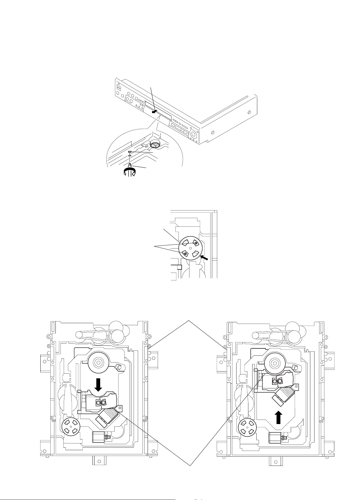
SERVICE NOTE
1. DISK REMOV AL PROCEDURE (at POWER OFF)
1) Insert a cross-tip screwdriver into a hole at the bottom, and rotate the cam gear 1 in direction A. (See Fig. 1)
Note: To prevent a damage of cam gear, rotate it in direction A by 1/4 turn.
2) Draw out the tray 2 in direction B by hand, and remove a disk. (See Fig. 1)
Fig. 1
2. NOTE ON MOUNTING SLED MOTOR
1) Push the sled motor assy 1 toward direction A. (See Fig. 2)
2) Tighten two screws 2 (M1.7 × 2.5).
1
Sled motor assy
2
Two screws (M1.7 × 2.5)
Fig. 2
3) Raising the MD block assy 3 90 º with the side down. confirm that the optical pick-up 4 falls by self weight. (See Fig. 3)
4) Further, with the front side of MD block assy 3 up, confirm that the optical pick-up falls by self weight.
Upper
3
MD block assy
Upper
Front side
Lower
Front side
4
Optical pick-up
Fig. 3
— 5 —
Lower
3. REPLACING OPTICAL PICK-UP
s
r
3-1. Handling
1) A red laser diode for DVD r equires more attention to static
electricity than general infrared laser diodes for CD.
Because its durability to static electricity is far weaker than
that of infrared laser diodes, always use an earth band when
handling the optical pick-up block as service parts.
2) As for the flexible board KHS-180A (RP) packed as service
parts, the short lands have been soldered to protect from static
electricity . Accordingly , remo ve solders when replacing optical
pick-up. (See Fig. 4)
DVD short land
3) In handling the KHS-180A (RP), do not touch inhibited parts
shown in Fig. 5, but grip the slide base bearing and U-shaped
guide.
Laser holder
Slide base bearing
Skew sensor
Lens actuator
covers
Objective lense
U-shaped guide
CD short land
Fig. 4 Flexible board
OEIC
Touch inhibited parts
• Objective lens
• Skew sensor
• Laser holder
• Laser coupler
• Flexible board
• OEIC
• Lens actuator covers
Flexible board
Connecto
Laser coupler
Fig. 5 KHS-180A (RP)
— 6 —
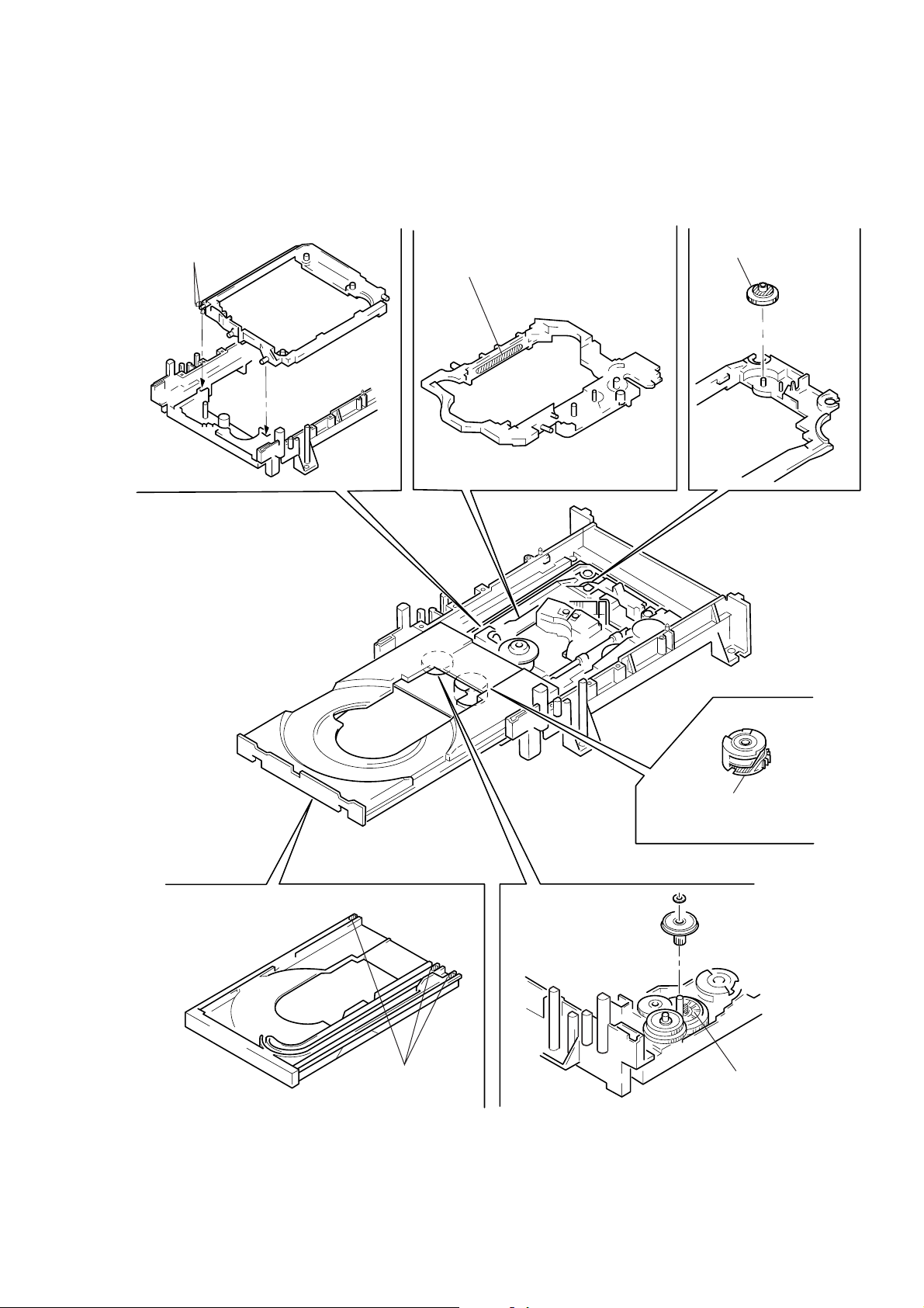
4. NOTE ON ASSEMBLING MECHANICAL DECK
4-1. Application of Grease
1) Grease must be applied if the following parts are replaced. (See Fig. 6)
Note 1: Recommended grease is Foil KG-70MP.
Note 2: In applying grease, take care not to allow grease to stick to other parts (particularly, rubber belt, spindle motor, and optical pick-up).
Base unit holder
2 bosses
Skew cam
Slide base
Tray 3 grooves
NOTE:Add grease if tray
moves slowly.
Cam gear
Loading pulley shaft
NOTE:Add grease if tray
generates noise
periodically.
Fig. 6
— 7 —

4-2. Cleaning Spindle Motor T urntable
1) Remove the tray. (Refer to 2-2)
2) Clean the spindle motor turntable if disc antiskid rubber (black)
is dirty. (See Fig.7)
Spindle motor
Turntable
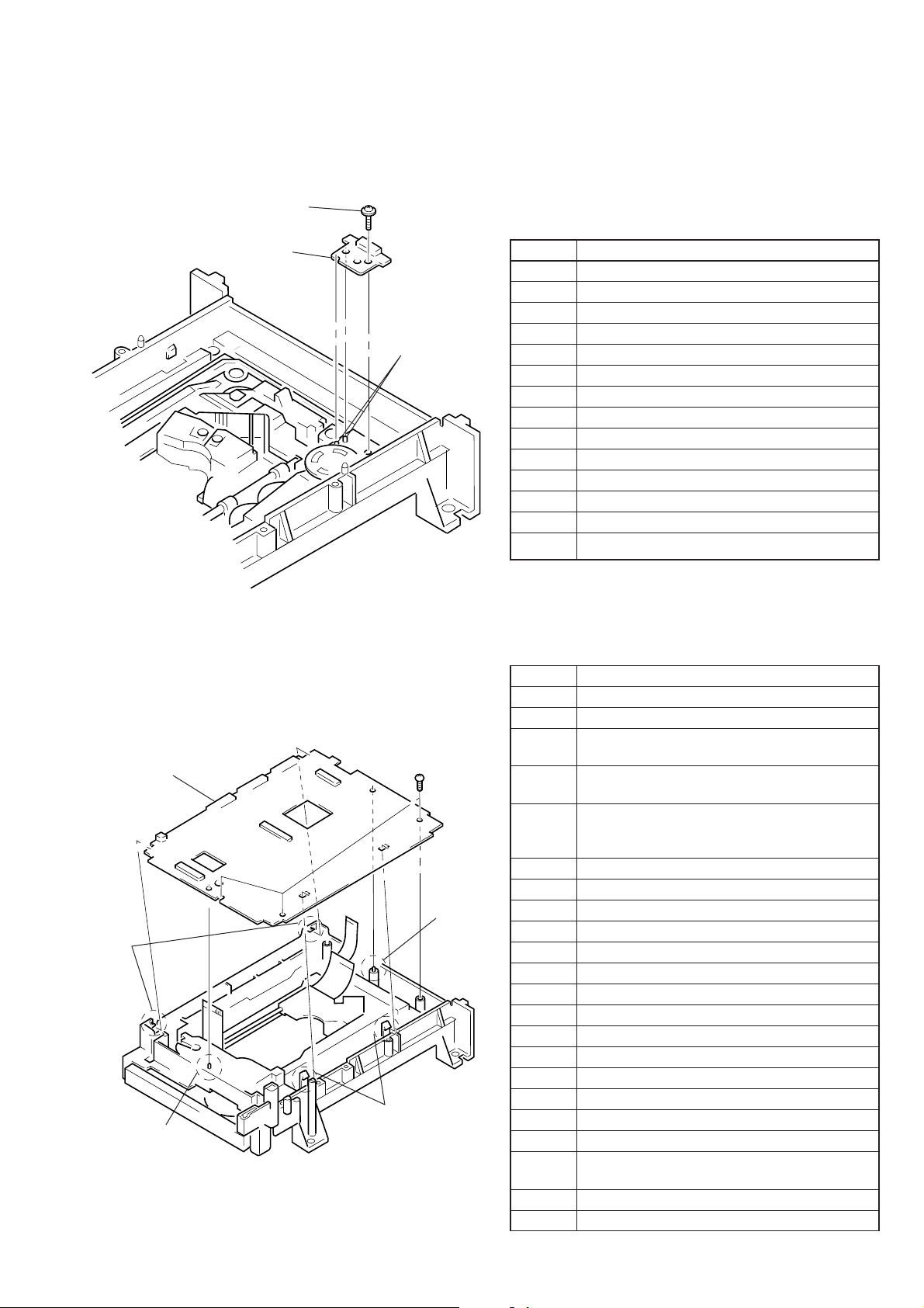
4-4. Deformation of Insulator
1) Assemble the spindle base into the base unit.
2) Lock with 4 shoulder screws. (See Fig. 9)
3) Check if 4 insulators deformed. (See Fig. 9)
Four step screws
Two insulators
Fig. 7
4-3. Aligning Phase of Cam Gear and Drive Gear
1) Align triangle marks when assembling the cam gear and dri v e
gear. (See Fig. 8)
Drive gear
Align triangle marks.
Cam gear
Fig. 8
Good
Insulator
NG
Two insulators
Fig. 9
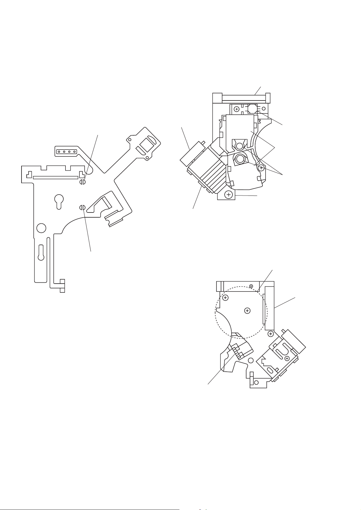
4-5. Note on Connecting OPT Harness
1) The optical pick-up could be destroyed unless the OPT harness
is connected normally to the connector. (See Fig. 10)
OPT harness
Good
Connector
NG
— 8 —
Fig. 10
4-6. Note on Mounting FG-43 Board
1) Align two bosses. (See Fig.11)
2) Fix the board securely with scre ws (PTPWH 2 × 5). (The sensor
will not function normally if the board floats up.)
Screw
(PTPWH2
FG-43 board
×
5)
Two bosses
5. EMERGENCY CODE INDICATION
5-1. Users are expected to take care of the
followings by themselves – – – – “C” code
“C : 13 : XX Clean the disc”
“C : 31 : XX Remove and insert the disc again”
XX
00
PON ready
10
Stop
20
Trace
30
Pause
40
Drvcon Unit
50
Mecha Unit
Spin Up
61
Tracking offset
62
Jitter/Gain
63
TOC/Control Data Read
60
Others
70
Spin Down
80
Seek
90
Error Recovery
Fig. 11
4-7. Note on Mounting TK-47 Board
1) Align two bosses. (See Fig.12)
2) Align four tabs. (See Fig.12)
3) Fix the board securely with 3 screws (BV 3 × 10). (The sensor
will not function normally if the board floats up.)
Three screws
TK-47 board
Two claws
Boss
Fig.12
(BV3
Two claws
× 10
)
Boss
5-2. Consult Sony Service – – – “E” code,
E : YY : ZZ
Refer to the item “5-8. Appendix” for details.
YY
01
EEPROM reading: NG (Check Sum has abnormality)
02
EEPROM writing: NG (Check Sum has abnormality)
EEPROM BUSY is displayed continuously exceeding
03
the specified time.
The pointer that shows the newest Emg History has
04
abnormality.
Communication between the HI microprocessor and
06
the SYS microprocessor is interrupted for a specified
time.
07
HI microprocessor cannot detect V-sync.
10
EEPROM CHECK NG
16
DSP CHECK NG
21
Sled driver has abnormal voltage.
30
Hy Det Level adjustment has abnormality.
31
Sled Offset Cancel adjustment has abnormality.
32
Focus Gain adjustment is faulty.
33
Tracking Offset adjustment is faulty.
34
Tracking Gain adjustment is faulty.
35
JITTER NG (only during the automatic adjustment)
40
Focus Servo does not lock in.
41
Focus Jump failed.
42
DSP Error Code (not used)
60
Mis-chucking when disc is inserted.
When disc started rotation, it did not reach the target
61
speed within 3 seconds.
62
Spindle runs away/does not stop.
63
Lock Check (in the service mode only)
— 9 —

YY
64
65
66
70
71
72
73
80
81
82
83
84
85
86
87
88
89
90
96
97
A0
A1
A2
A3
A4
A5
A6
A7
B0
B1
B2
B3
B4
B5
B6
B7
B8
C0
C1
D0
D1
E0
E1
CL V servo does not lock in within the specif ied time.
FG servo does not reach the target speed within the
specified time.
Spindle is not rotating at x1 speed. (RF Edge)
System control requests address that does not exist.
System control requests time code that is not used.
System control requests track No. that is not used.
The lock-in operation is not completed within the
specified number of times.
Continuity of address has abnormality. (DVD)
Cannot read address even retry is executed. (CD)
TOC read is not completed within the specified period
of time.
Physical Information Read Error ( CTRL DATA ECC
ERR)
Physical Information Read Error ( CTRL DATA
INSA ERR)
Physical Information Read Error ( CTRL DATA
FULL ERR)
Physical Information Read Error ( CTRL DA TA RUN
OVER)
Physical Information Read Error ( CTRL DATA Time
Out)
Layer No has abnormality.
CD Text Data Read Error
Servo recovery has failed when starting a disc.
Auto Sequence Time Out
Auto Sequence has exceeded the specified times.
Stop request from drive microprocessor
Did not return to the mode for a specified time.
Feed error. Retry is impossible.
GetInfo error. Stop
An attempt is made to playback a DVD-R Disc
Failed to execute Decrypt
SlowR. Target address of searching is illegal.
Feed error. Stop
Due to feeder.
Due to video hang-up
Error in DMX
Waiting for data from SlowR
Navi Pack sector address is different during SlowR
mode
Video hang-up during SlowR mode
Time out while waiting for ending of SlowR Gttgt
Waiting for data during FF/FR
Waiting for video data during FF/FR
The installed HI microprocessor ROM does not match
the destination.
HI microprocessor UART1 communication port has
abnormality.
EMG code is not present upon power-of f request from
drive microprocessor
Cannot return t stop mode. Power Off
Drive microprocessor - system error (ST ATUS ERR)
Drive microprocessor - system error (MECHAM
MODE ERR)
ZZ
FF
00
01
02
12
03
13
04
14
05
15
UNKONWN
NO DISC
CD 12 cm
CD 8 cm
SINGLE DVD 12 cm
SINGLE DVD 8 cm
DUAL 12 cm
CDR 12 cm
CDR 8 cm
DVDR 12 cm
DVDR 8 cm
— 10 —

SECTION 1
GENERAL
DVP-K800D
This section is extracted from
instruction manual.
1-1

1-2

1-3

1-4

1-5

1-6
1-7

1-8

1-9
1-10

1-11
1-12

1-13E

SECTION 2
s
)
DISASSEMBLY
NOTE: Follow the disassembly procedure in the numerical order given.
2-1. UPPER CASE
1
Tapping screws
1
Tapping screws
DVP-K800D
Case
2
Vertically up
Front panel
2-2. FRONT PANEL BLOCK ASSEMBLY
Case
1
Tapping screw
6
Front panel block
assembly
Remove hooks on both
sides and bottom
5
Screw
+BVTP3 × 8
4
Tray ornamental
plate assembly
a
Connector
1
3
Tray
slides out
CN205
5
Screw
+BVTP3
2
Turn cam gear
from the bottom
Philips screwdriver
or equivalent
×
a
1
Flat cable
(From CN601 on MB-78 board
8
1
Connector
CN501
2-1
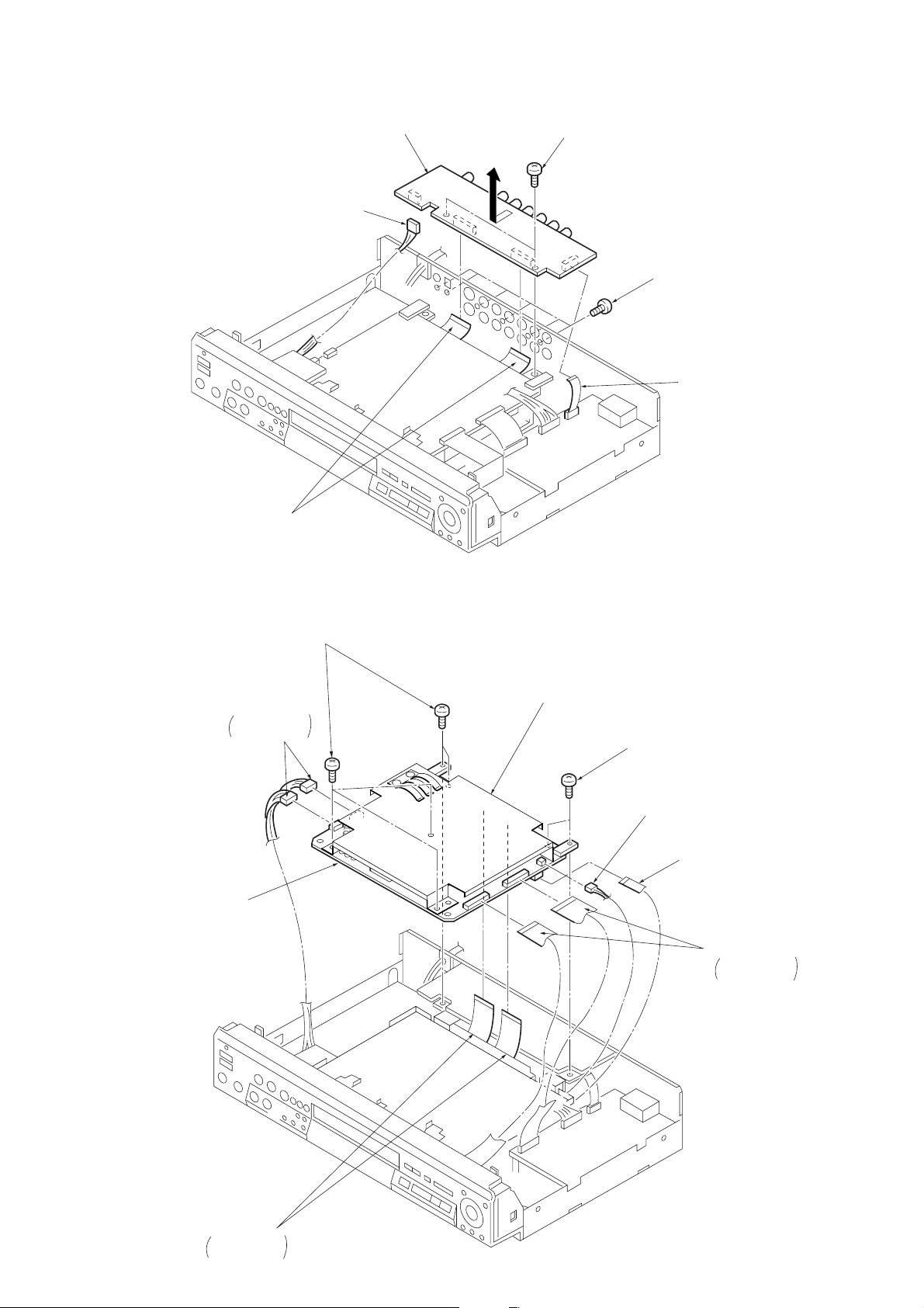
2-3. AU-217 BOARD
AU-217 board
1
Connector
(From CN205)
5
Flat cables
(From CN201and CN203)
4
3
Screws
+BVTP 3
×
8
2
Screws
+BVTP 3 × 10
1
(From CN204)
Flat cable
2-4. MB-78 BOARD
5
MB-73 board
2
+BVTP 3 × 8
1
Connectors
From CN001
and CN002
Screws
3
Cover (upper)
2
Screws
+BVTP 3 × 8
1
Connector
(From CN361)
1
Flat cable
(From CN301)
1
From CN601
and CN702
Flat cables
4
Flat cables
From CN101
and CN252
2-2

2-5. KR-35 BOARD
0
1
Flat cable
(From CN502)
1
Connector
(From CN501)
1
Flat cable
(From CN503)
3
Screws
+BVTP 3 × 8
4
KR-35 board
2
Screw
+BVTP 3 × 1
2-6. POWER BLOCK
1
(From CN201)
Connector
2
Screws
+WHD B3
1
Connector
(From CN101)
3
Power block
2-3

2-7. TK-47 BOARD
8
)
3
+BVTP 3 × 8
Screws
1
Screws
+BVTP 3
×
8
2
Chassis bracket (B)
3
Screws
+BVTP 3 × 8
Mechanism deck
4
Flexible board
(From CN001)
4
Flexible board
(From CN002)
5
Screws
+BVTP 3 × 10
2-8. HP-116 BOARD, MC-115/VR-68 BOARD BLOCK,
FL-106 BOARD, FR-156 BOARD
1
Screw
+BVTP 2.6 × 8
3
4
Screws
+BVTP 2.6 × 8
MC-115/VR-68
board block
TK-47 board
4
(From CN004
2
Screws
+BVTP 2.6 × 8
Connector
5
HP-116 board
5
Connector
Front panel assembly
6
Flexible cable
From S1
rotary encoder
2-4
7
Screws
+BVTP 2.6 × 8
9
FR-156 board
0
FL-106 board
7
Screws
+BVTP 2.6
×

2-9. CIRCUIT BOARDS LOCATION
Power Block
AU-217
AUDIO D/A CONVERTER,
LINE OUT
FG-43
(SLED MOTOR)
TK-47
(RF, SERVO)
KR-35
KARAOKE
DSP/
MIC 3, 4 JACKS
FL-106
DISPLAY,
OPERATION SWITCHES
MB-78
VIDEO, SERVO/SYSTEM
CONTROL, AUDIO
MC-115
MIC 1, 2
JACKS
FR-156
POWER
SWITCH
HP-116
PHONES
JACK
VR-68
MIC/ECHO
LEVEL
2-5E

3-1. OVERALL BLOCK DIAGRAM
SECTION 3
DVP-K800D
BLOCK DIAGRAMS
OPTICAL PICK-UP
BLOCK
KHS-180A/JIN
A
B
C
DVD
PD IC
D
RFP
LD
DVD LD
PD
MODULE
IN
SKEW
OUT
SENSOR
CD E
CD F
PD1
CD
LAZER
PD2
COUPLER
LD
PD
FCS+
DVD
FCS-
FOCUS
TRK+
TRACKING
COIL
TRK-
FCS+
FCS-
CD
FOCUS
TRK+
TRACKING
COIL
TRK-
U 1,2
V 1,2
W 1,2
M901
SPINDLE
MOTOR
SP VH+,-
M
U,V,W
TK-47 BOARD
IC006
DVD
DIGITAL
SERVO
IC005
CD
APC RF
IC501
HALL
IC
IC502
M501
SLED
M
MOTOR
FG-43 BOARD
DVD RF
FE
TE
PI
SCKG3
TIE
CD RF
FE
TE
CD RF DC
TE ATT
M903
LOADING
MOTOR
M902
TILT
MOTOR
SSSD
IC011
SW
M
M
HA+,HB+,VH+,-
SLD MT+,-
MB-78 BOARD
16
IC363
FOCUS
TRACKING
COIL
DRIVE
IC303
SPINDLE
MOTOR
DRIVE
IC361
LOADING
TILT
MOTOR
DRIVE
IC302
SLED
MOTOR
DRIVE
IC452
SEL
IC455
OPN/CLS
HY CNTR,SLD FS
IC502
IC502
IC503
IC301
ERROR
SP CTL0,1
SP GC1,2
HYS DET
IC503
IC503
IC501
IC508 IC501
TRINT
DFCTA
RF1
RF2
FE
IC506
TE
DSP
IC806
ARP
SPD IF
CD DATA
CD BCK
CD LRCK
8
ID0-7
IA0-7
IC810
4M
DRAM
33M
27M DSP
XRST
8
F OUT
T OUT
AMP
SL +,-
13.5M
SSSD
SCKG3
SOG3
27M VE
IC804
L G/A
8 8
8
IFSI
OPN/CLS
SPCTL0.1
IFSO
SPGC1,2
IC801
EEPROM
A1
27M DSP
SDP RST
ACK
CLAP SW0,1
ACSI
SOG4,SCKG4,SCKG4
27M GA
M RST
OH SYNC
H SYNC
8 16
SRST
IC802
1M
SRAM
ACK
SDP RST
VSI
AVCK
SCKG2
SIG1
SIG2
SCKG2
1616
IC803
8M
FLASH
1917
XRST
HD0-15
HA0-7,19,20,21
SD0-7
V SYNC
22
M RST
IC805
SH
SOG2
IC205
IC206
DAC RST
8
8
6
IC205
AC3 RST
IC811
DECRYRT
ID0-7
IA0-7
XRST
27M GA
DCR SD0-7
ID0-7
8
IA0-8
9
CD DATA
CD BCK
CD LRCK
MRST
IC807
S G/A
9
8
8
6
IC203
MPEG2 A/V
DOLBY
DIGITAL
DECODER
16M
SDRAM
IC201
IC202
SO
SCLK
IC605
RESET
ACLK
27M VE
R/G/B
IC208
SPDIF AC3
R/G/B
SO
SCLK
13.5M
IC204
AU-217 BOARD
8YC0-7
IC251
DNR
C0-7
MRST
13.5M
OH SYNC
SCKG3
SOG3
27M DNR
H SYNC
V SYNC
H SYNC
V SYNC
VSI
SOG2
AVCK
IC204 IC206
H SYNC
IC207
V SYNC
OSD
M RST
M RST
SOG2,SCKG2
SOG4,SCKG4,SCKG4
ACSI
CLAP SW0,1
AC3 RST
8Y0-7
8
IC206
IC252
VIDEO
ENCODER
SOG3
SCKG3
DAC RST
IC205
768FS
Y
C
V
IC205
IC209
PLL
M RST
SOG4
SCKG4
IC102
DIR
IC104
AC3
DECODER
IC105
256k
SRAM
DATA
BCK
LRCK
SOG2
SCKG2
IC101
M G/A
DAC RST
768FS
HD OUT
AC3 RST
KR DATA
KA DATA
KR BCK
KR LRCK
SCKG3
SOG3
384FS 2CH
DAC DATA
DAC BCK
DAC LRCK
M RST
DD DATA F
DD BCK
DD LRCK
SOG4
SCKG4
M RST
384FS
DD DATA R
DD BCK
DD LRCK
SOG4
SCKG4
M RST
384FS
DD DATA C
DD BCK
DD LRCK
SOG4
SCKG4
384FS
M RST
IC215
2CH
D/A CONV.
IC203
L,R
D/A CONV.
IC204
SL,SR
D/A CONV.
IC205
C,SW
D/A CONV.
IC353
Y
IC351
C
VIDEO
D/A
V
IC206
IC207
IC208
IC211
SW
IC209 IC212
IC210
IC213
IC214
IC352
OPTICAL
DIGITAL
OUT
J354
L R
S VIDEO
OUT
VIDEO
L
AUDIO
OUT
R
IC001
HP-116
BOARD
FLONT
REAR
CENTER
WOOFER
J201
5.1CH
OUTPUT
J001
PHONES
FL-106 BOARD
ECHO CONT
MIC2 IN
IC806
MIC1 IN
MIC CONT
MIC
IC503
MROM
KR DATA
KA DATA
KR BCK
KA LRCK
768FS
SOG2
SCKG2
KARAOKE
S101-112
S116,117
S119-123
FUNCTION
KEY
S114,115,118
FUNCTION
KEY
S401
ON/
STANDBY
IC401
REMOTE
CONTROL
RECEIVER
ND101
FLUORESCENT
INDICATOR
TUBE
SW
BLOCK
J103
CONTROL
J102
MIC2
MIC1
IC102
MC-115
BOARD
MIC4
MIC3
CLAP SW0
CLAP SW1
J601
ECHO
IC804
VR-68 BOARD
IC101
DISPLAY
DRIVE
AD3,4-6
SI
SCLK
SI
SCLK
IC604
MIC1,2
I/F
MIC CONT
MYCON
ECHO CONT
IR
SCKG1
D0-7
IC601
SRST
IFSO
IFSI
8 8
BUFFER
BOARD
A0-18
FR-156
8
AD4-6
AD3
AD4
IR
IC603
SOCKET
IC508
DSP
KR-35 BOARD
IC517
IC507
MIC
HAKUSYU
3-1 3-2

DVP-K800D
3-2. RF/SERVO BLOCK DIAGRAM
TK- 47 BOARD
OPTICAL PICK-UP
BLOCK
KHS-180A/JIN
DVD
PD IC
DVD LD
MODULE
SKEW
SENSOR
CD
LAZER
COUPLER
DVD
FOCUS
TRACKING
COIL
CD
FOCUS
TRACKING
COIL
SPINDLE
M901
SPINDLE
MOTOR
M
M903
LOADING
MOTOR
16
RFP
99
RFM
10
A
14
B
13
C
6
D
18
VR
5
DVD LD
3
DVD PD
4
VLD
2
SKEW IN
41
SKEW OUT
42 42
LED
38
CD E
27
CD F
20
PD1
28
PD2
29
AL
19
CD LD
23
MON
26
VR
25
DVD FCS+
34
DVD FCS-
35
DVD TRK+
36
DVD TRK-
37
CD FCS+
30
CD FCS-
31
CD TRK+
33
CD TRK-
32
U IN1
10
U IN2
9
V IN1
8
V IN2
7
W IN1
6
W IN2
5
SP VH+
11
SP VH-
12
U OUT
13
V OUT
14
W OUT
15
LD MT+
1
M
LD MT-
Q010
BUFFER
CN001
10
14
13
6
18
Q004
5
SWITCH
3
4
Q005
SWITCH
2
41
Q001
TILT
38
LED ON
27
20
28
29
19
Q007
SWITCH
23
26
25
34
35
36
37
30
31
33
32
CN002
10
9
8
7
6
5
11
12
13
14
15
CN004
1
22
IC004
3167
D004
IC006
DVD DIGITAL SERVO
SIGO
63
RFP
SDATA
64
RFM
SCLK
10
A
SDEW
B
9
8
C
7
D
1
A2
2
B2
3
C2
4
D2
18
LD
17
PD
PI
20
TI A
TE
TI B21
FE
MIRR
HOLD1
FDCHG
TIOF
TIE
TII
IC005
CD APC RF
MIRR
5
E
6
F
RFO1
3
PD1
4
PD2
9
CE
APC ON
RFO
1
LD
TE
FE
2
PD
TEC
57
44
43
45
16XLDON
37
38
39
30
47
33
19
26
23
19
22
21RFO2
25
32
13
15
12
IC303 !ª@™@£ DVD
6.6 µsec
IC303 !ª@™@£ CD
11 msec
4.6 Vp-p
2.5Vp-p
Q008
SWITCH
S5V
CN451 1 CD
0.5 V/div
0.2 µsec/div
CN451 3 DVD
0.5 V/div
0.1 µsec/div
CN005
PH001
CHUCK
SENSOR
IC011
5
4
3
9
2
15
1
10
13
14
12
11
Q009
CN008
CN501 CN301
IC501
IC502
H
H
M501
SLED
MOTOR
M
FOR CHECK
26
16
19
18
17
3
6
5
21
12
23
15
20
13
22
14
1
9
2
4
10
11
22
20
18
16
23
21
19
17
8
7
6
5
4
3
10
9
11
12
13
14
15
MOTOR
7
8
5
4
6
3
1
2
CHECK
DVD RF+
CD RF
SSSD
SCKG3
SDEN
TILT/H
CHUCK
TRAY
DVD LDON
CD LD ON
DVD PI
CD RFDC
DPD
CD TE
DVD FE
CD FE
MIRR
DFCTS
TE ATT
TI OFS
TI ERR
TIE
DVD FCS+
DVD FCSDVD TRK+
DVD TRK-
CD FCS+
CD FCS-
CD TRK+
CD TRK-
U IN1
U IN2
V IN1
V IN2
W IN1
W IN2
SP VH+
SP VH-
U OUT
V OUT
W OUT
LD MT+
LD MT-
M902
TILT
HA+
HA-
HB+
HBVH+
VH-
SLD MT+
SLD MT-
CN303
FOR
CN451
M
FG-43 BOARD
FE
3
TE
4
PI
1
JIT PWM
5
CD RF
1
DVD RF+
3
CN452
2
12
9
10
11
25
22
23
7
16
5
13
8
15
6
14
27
19
26
24
18
17
CN302
6
8
10
12
5
7
9
11
20
21
22
23
24
25
18
19
17
16
15
14
13
CN361
1
2
2
1
4
5
3
6
8
7
MB-78 BOARD
SSSD IC804
SCKG3 IC804
SDEN IC804
TILT/H IC804
ACHUCK IC804
ATRAY IC804
DVD LDON IC804
CD LDON IC804
IC452
SELECTOR
13
12
1
2
3
5
3,6 1,7
IC455
IC363
FOCUS/TRACKING
COIL DRIVER
16
DF+
15
DF-
17
DT+
18
DT-
13
CF+
14
CF-
12
CT+
11
CT-
IC303
SPINDLE
MOTOR DRIVER
30
U1
31
U2
32
V1
33
V2
34
W1
1
W2
29
VH+
28
VH-
23
U OUT
22
V OUT
19
W OUT
8
OUT2+
9
OUT2-
6
OUT1+
5
OUT1-
34
HA+
33
HA-
30
HB+
29
HB-
23
VH+
22
VH-
2
MTR+
5
MTR-
14
11
15
10
4
9
MUTE1
MUTE2
SPCTL0
SPCTL1
SPGC1
SPGC2
MUTE1
MUTE2
CTRL
HFG
NS+
IN1+
IN2-
TKC
CA+
Q452
IN4
IN3
IN1
IN2
VC
DVI
DVER-
52
46
48
13
TO/FROM
SYSCON
27
(Page 3-9)
28
2
3
26
23
3
6
9
20
27
7
9
8
11
10
13
21
17
2
13
TILT/LOADING
MOTOR DRIVER
MOTOR DRIVER
12
8
11
25
18
17
BLOCK
IC361
IC302
SLED
IC502
12 14
57
10 8
67
IC503
TOFC 1,2 IC804
CD/DVD IC804
HFG IC805
NST IC804
SPCTL0 IC804
SPCTL1 IC804
SPGC1 IC804
SPGC2 IC804
OPN/CLS IC804
S12V OFF IC804
TRAY FREE IC804
IC503
3
1
IC508 IC501
576
21
IC501
2,3
1
IC503
10
8
141
4
97
7
9
8
22
10
5
19
18
Q501
BUFFER
IC503
14
Q371
Q372
142
5
13
FROM
SYSCON
BLOCK
(Page 3-9)
IC806 %ª-^™^¢-^¶ DVD
IC506
DIGITAL SIGNAL
PROCESSOR
63
21
AIN5
7
89
TRINT
7
DFCTA
8
GIO6
24
AIN1
26
AIN0
88
TRREF
12
GIO2
11
GIO3
73
PWM2
22
AIN4
46
AOUT1
49
AOUT2
1
GIO12
2
GIO11
41
AOUT2
38
AOUT3
74
PWM1
75
PWM0
14
GIO0
18
AIN8
19
AIN7
20
AIN6
HD0
8
56
HD7
HLDB
72
CLKIN
65
TCK
79
IC506 ^∞ DVD/CD
4.6 Vp-p
27 MHz
122
IC806
4.8 Vp-p
27 MHz
IC806 (º DVD/CD
3.3 Vp-p
3.375 MHz
106
IC806 CD
1 V/div
0.2 µsec/div
IC806 $• DVD
71HWR
70HRD
ERROR
98
FON
100
BUSY
4
ACK
3
MRST
84
IRS
94
7
56µsec
IC301
ERROR AMP
5
2.5Vp-p
216
52
JITPWM
10
RF IN1
12
RF IN2
122
MCKI
48
MDP0
43
MDS0
SDSP WR IC804
SDSP RD IC804
ERROR IC804
FON IC804
BUSY2 IC804
ACK IC805
SDP RST IC805
2 V/div
0.1 µsec/div
IC806
ARP
77
58
15
17
14
63
MD15
1
SD0
SD7
SDEF
XSAK
XSRQ
XSHD
SDCK
SCKI
D OUT
DATA
BCLK
LRCK
XWR
XRD
DFCT
MUTE
MD2
FWON
XINT
XCS
XWAT
LOCK
MD0
MA0
MA8
XMWR
XCAS
XRAS
XOE
D0
D7
A0
A7
59
62
.
64
67
70
73
.
75
78
96
99
.
101
104
94
93
92
91
90
124
109
106
107
108
56
57
84XRST
51NORF
50
110
112
55
80
81
83
53
156
159
.
161
164
.
166
169
.
171
174
137
139
.
141
.
143
.
145
147
150
151
153
154
TO/FROM
SYSCON
BLOCK
(Page 3-9)
IC807
ID0-7
A1
IA0-7
IC811
DECRYPT
41
SHD0
88
34
SHD7
31
SHA0
IC810
4M DRAM
DQ1
DQ16
6
SHA7
26
74
77
.
79
DTI0
.
8
80
DTI7
.
1
.
3
5
EFLGI
6
ACKI
8
REQO
4
SHDRI
7
DCKI
2
5
.
7
10
.
16
35
38
.
40
43
8
16
18
A0
21
.
9
A8
24
28
15
WE
30
UCAS
31
LCAS
16
RAS
29
DE
DTO1
DTO7
EFLGO
ACKO
REQI
SHDRO
MCK
HCS
WAIT
WRN
RDN
71
68
.
66
64
.
62
60
59
56
61
51
46
INT
43
47
45
44
54XRST
8
8
8DCR SD0-7
DCR SD0-7
ID0-7
41 38
53 52
IA0-7
27M DSP IC206
ERROR IC203
AVALID IC203
AREQ IC203
TOS IC203
27M DNR IC206
DCK IC203
33M IC205
SPDIF IC203
CD DATA IC203
CD BCK IC203
CD LRCK IC203
DCR INT IC804
DCR CS IC804
DCR WT IC804
IWR IC804
IRD IC804
MRST IC805
XRST IC805
NORF IC804
DFCT IC804
MUTE IC804
MD2 IC804
FWON IC804
ARP INT IC804
ARP CS IC804
ARP WT IC804
LOCK IC804
.
36 33
TO/FROM
SYSCON
IC807
.
.
IC203
12 19
50 44
BLOCK
(Page 3-9)
11
24
26
30
21
6
TO/FROM
VIDEO
BLOCK
(Page 3-5)
28
11
102
101
98
99
63
62
64
57
56
54
98
TO/FROM
SYSCON
BLOCK
106
(Page 3-9)
105
104
103
102
60
59
61
16
3-3 3-4
 Loading...