

Sony DSR-PD100, DSR-PD100P Service Manual
DSR-PD100/PD100P
RMT-811
US Model
Canadian Model
DSR-PD100
SERVICE MANUAL
1999. 04
SUPPLEMENT-1
File this supplement-1 with the Service Manual.
(EVB00374, EVB00850, EVB01385)
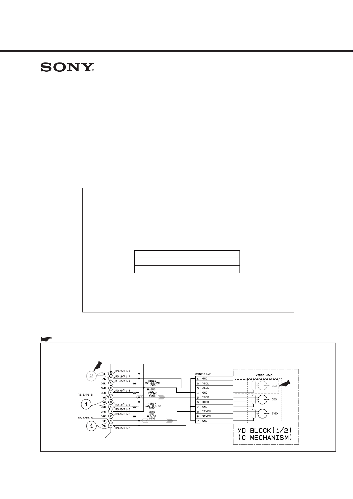
• The video head (SLD) circuit should be deleted from the
schematic diagram.......................................................(page 1)
• Several parts are added and changed................ (pages 2 to 4)
• The DC IN circuit is separated from the VI-151 board. A new
independent printed wiring board PS-422 is newly added solely
for the DC IN board...........................................(pages 5 to 18)
Applicable serial Nos.
Models
DSR-PD100
DSR-PD100P
1000701 and higher
AEP Model
DSR-PD100P
Serial Nos.
undecided
• Part number change of IC1602 on the VI-151 board.
IC1602 : CXD3200R-T6 → SN104266PN-TEB
..................................................................... (pages 19 and 20)
• Addition of MF ring assy ............................................(page 21)
• Add and correct your service manual.
: Deleted portion.
[ Page: 4-52 ]
VI-151 BOARD (1/10) SCHEMATIC DIAGRAM
Delete the waveform 2.
: Added portion. : Chenged portion. : Deleted portion.
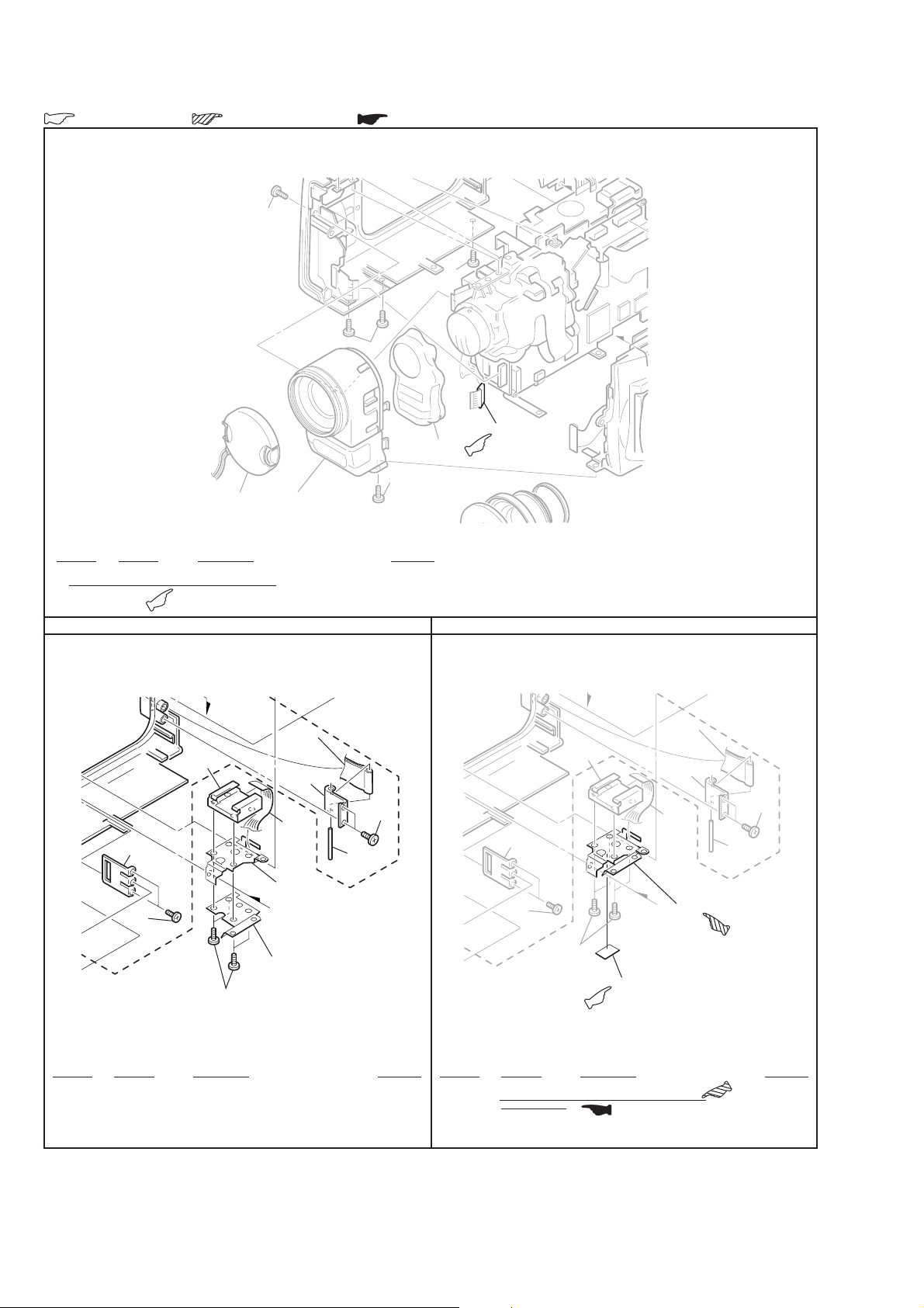
[ Page: 6-1 ]
6-1-1. OVERALL SECTION
2
2
2
7
2
Front panel assembly
1
(See page 6-9)
Ref. No. Part No. Description Remarks
15 1-469-391-11 CORE, FERRITE
15
Old New
[ Page: 6-3 ]
6-1-3. CABINET (L) SECTION
119
121
110
113
101
107
114
6-1-3. CABINET (L) SECTION
119
121
110
113
101
107
114
120
101
126
101
105
not supplied
120
105
Ref. No. Part No. Description Remarks Ref. No. Part No. Description Remarks
120 3-051-903-01 RETAINER, SHOE
126 3-053-541-01 REINFORCEMENT, SHOE
* 120 3-055-501-01 RETAINER, SHOE (HSD)
126
— 2 —
: Added portion.
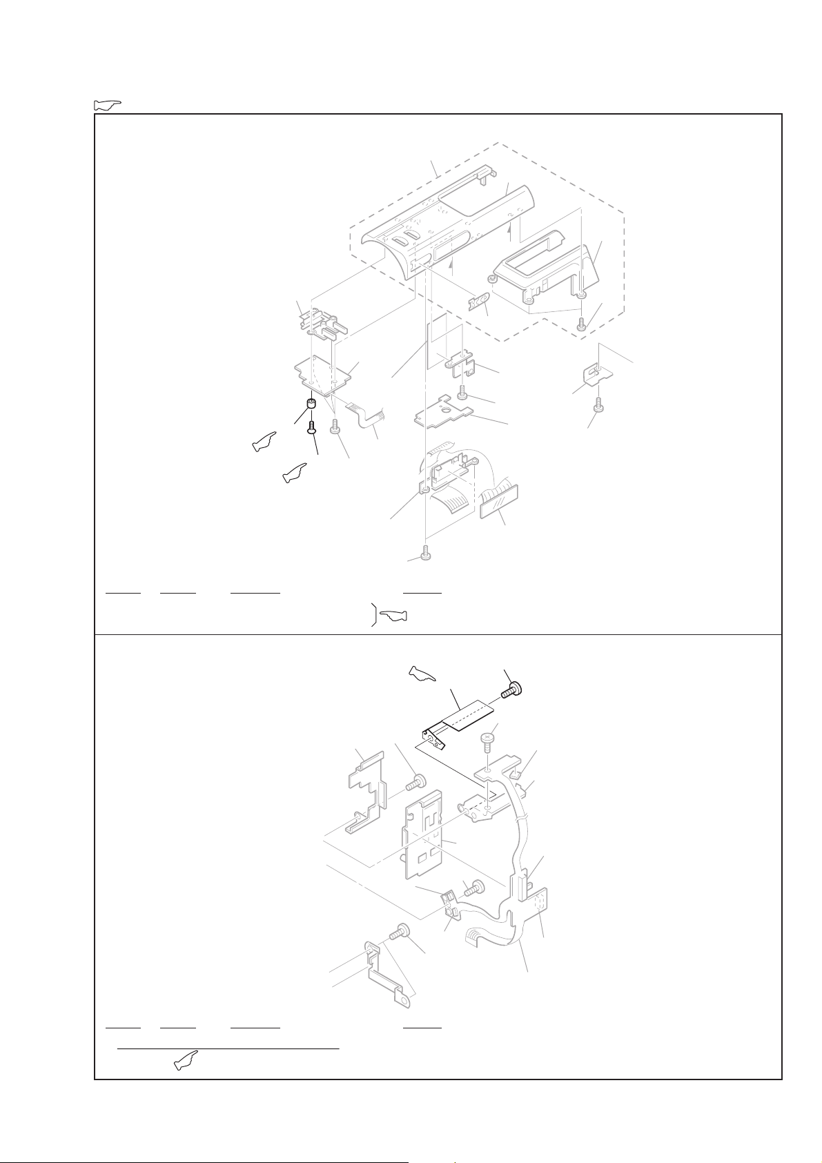
[ Page: 6-7 ]
6-1-7. CABINET (UPPER) SECTION
306
not
supplied
305
304
not supplied
320
303
321
302
312
301
Ref. No. Part No. Description Remarks
* 320 3-054-047-01 SHAFT, F PANEL HOLD (ø4X1)
321 3-724-437-01 SCREW (K2X4)
b
a
301
307
309
308
311
314
302
301
313
[ Page: 6-9 ]
6-1-9. FRONT PANEL SECTION
416
406
PH700
PH701
406
Ref. No. Part No. Description Remarks
427 X-3949-421-1 HOLDER ASSY, F PANEL
427
410
417
406
410
S702
418
S700
S701
426
— 3 —
: Added portion.
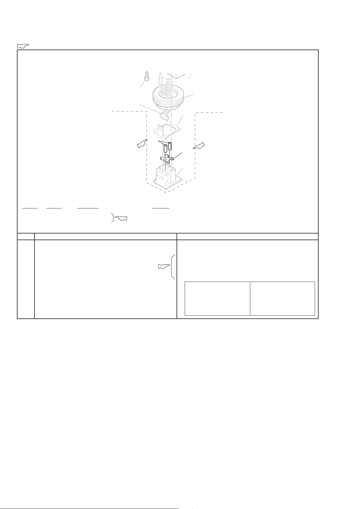
[ Page: 6-11 ]
6-1-11. XLR BLOCK
504
502
518
Ref. No. Part No. Description Remarks
518 3-054-320-01 SHAFT, FIXED
519 3-054-321-01 SPACER, PLUG
OldPage New
6-36E
514
515
519
516
ACCESSORIES
! 1-775-843-21 CORD, POWER (WITH FILTER)(3PIN)
1-790-524-11 CORD, CONNECTION (DV)
Note :
The components identified by
mark ! or dotted line with mark
! are critical for safety.
Replace only with part number
specified.
************
(WITH CLAMP FILTER) (2M) (PD100P)
Note :
Les composants identifiés par
une marque ! sont critiques
pour la sécurité.
Ne les remplacer que par une
pièce portant le numéro spécifié.
(PD100P)
— 4 —
)
: Added portion.
DSR-PD100/PD100P
< > :Page No. shown in < > indicates the page to refer on this Supplement-1.
[ ] : Page No. shown in [ ] indicates the page to refer on the original Service Manual
DSR-PD100/PD100P.
[ Page: 3-5 ]
3-2. POWER BLOCK DIAGRAM
PS-422 (DC IN) PRINTED WIRING BOARD
— Ref. No. PS-422 Board; 10,000 Series —
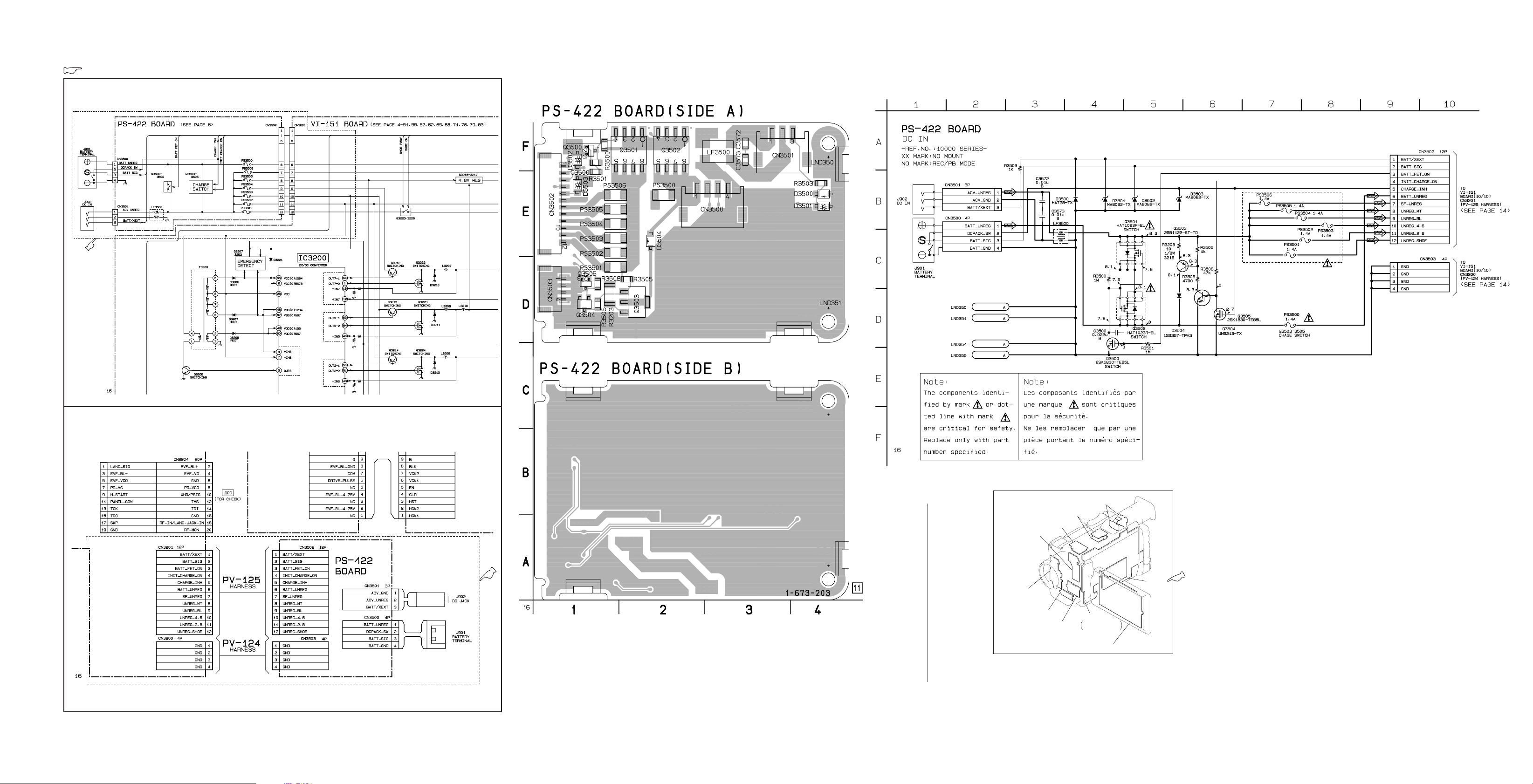
[ Page: 4-7 ]
FRAME SCHEMATIC DIAGRAM-2
PS-422 BOARD
C3500 F-1
C3572 F-3
C3573 F-3
CN3500 E-3
CN3501 F-3
CN3502 E-1
CN3503 D-1
D3500 E-4
D3501 E-4
D3502 F-1
D3503 E-1
D3504 E-2
LF3500 F-3
PS3500 E-2
PS3501 D-1
PS3502 E-1
PS3503 E-1
PS3504 E-1
PS3505 E-1
PS3506 E-1
Q3500 F-1
Q3501 F-2
Q3502 F-2
Q3503 D-2
Q3504 D-1
Q3505 D-1
R3203 D-1
R3500 F-1
R3501 E-1
R3503 E-4
R3505 D-2
R3506 D-1
R3508 D-1
ED-48
(USER CONTROL)
SE-75
(YAW/PITCH SENSOR)
JK-163
(AUDIO/VIDEO IN/OUT)
RI-10
(SIRCS RECEIVER)
MA-333
(STEREO MIC AMP)
LB-55
(EVF BACK-LIGHT)
VF-121
(COLOR EVF)
PS-422
(DC IN)
CK-80
USER CONTROL,
LCD DRIVE
PD-101
(RGB DRIVER, TIMING GENERATOR, BACK-LIGHT
— 5 — — 6 — — 7 —
 Loading...